JP5057649B2 - Double and triple gate MOSFET devices and methods of manufacturing these MOSFET devices - Google Patents
Double and triple gate MOSFET devices and methods of manufacturing these MOSFET devicesDownload PDFInfo
- Publication number
- JP5057649B2 JP5057649B2JP2004546872AJP2004546872AJP5057649B2JP 5057649 B2JP5057649 B2JP 5057649B2JP 2004546872 AJP2004546872 AJP 2004546872AJP 2004546872 AJP2004546872 AJP 2004546872AJP 5057649 B2JP5057649 B2JP 5057649B2
- Authority
- JP
- Japan
- Prior art keywords
- gate
- fin
- forming
- mosfet
- double
- Prior art date
- Legal status (The legal status is an assumption and is not a legal conclusion. Google has not performed a legal analysis and makes no representation as to the accuracy of the status listed.)
- Expired - Lifetime
Links
- 238000000034methodMethods0.000titleclaimsdescription38
- 238000004519manufacturing processMethods0.000titledescription12
- XUIMIQQOPSSXEZ-UHFFFAOYSA-NSiliconChemical compound[Si]XUIMIQQOPSSXEZ-UHFFFAOYSA-N0.000claimsdescription14
- 229910052710siliconInorganic materials0.000claimsdescription14
- 239000010703siliconSubstances0.000claimsdescription14
- 239000000758substrateSubstances0.000claimsdescription11
- 239000004065semiconductorSubstances0.000claimsdescription10
- 239000011810insulating materialSubstances0.000claimsdescription7
- 238000000151depositionMethods0.000claimsdescription6
- 230000005669field effectEffects0.000claimsdescription3
- 238000000059patterningMethods0.000claims2
- 239000010410layerSubstances0.000description19
- 230000008569processEffects0.000description17
- 239000000463materialSubstances0.000description11
- 239000003989dielectric materialSubstances0.000description5
- 238000005530etchingMethods0.000description4
- 238000012986modificationMethods0.000description4
- 230000004048modificationEffects0.000description4
- 229910052581Si3N4Inorganic materials0.000description3
- 238000010586diagramMethods0.000description3
- HQVNEWCFYHHQES-UHFFFAOYSA-Nsilicon nitrideChemical compoundN12[Si]34N5[Si]62N3[Si]51N64HQVNEWCFYHHQES-UHFFFAOYSA-N0.000description3
- PXHVJJICTQNCMI-UHFFFAOYSA-NNickelChemical compound[Ni]PXHVJJICTQNCMI-UHFFFAOYSA-N0.000description2
- KDLHZDBZIXYQEI-UHFFFAOYSA-NPalladiumChemical compound[Pd]KDLHZDBZIXYQEI-UHFFFAOYSA-N0.000description2
- VYPSYNLAJGMNEJ-UHFFFAOYSA-NSilicium dioxideChemical compoundO=[Si]=OVYPSYNLAJGMNEJ-UHFFFAOYSA-N0.000description2
- BOTDANWDWHJENH-UHFFFAOYSA-NTetraethyl orthosilicateChemical compoundCCO[Si](OCC)(OCC)OCCBOTDANWDWHJENH-UHFFFAOYSA-N0.000description2
- 238000005229chemical vapour depositionMethods0.000description2
- 238000010894electron beam technologyMethods0.000description2
- 238000005516engineering processMethods0.000description2
- 238000010438heat treatmentMethods0.000description2
- 229910052751metalInorganic materials0.000description2
- 239000002184metalSubstances0.000description2
- 238000000206photolithographyMethods0.000description2
- BASFCYQUMIYNBI-UHFFFAOYSA-NplatinumChemical compound[Pt]BASFCYQUMIYNBI-UHFFFAOYSA-N0.000description2
- 238000005498polishingMethods0.000description2
- 229910021420polycrystalline siliconInorganic materials0.000description2
- 238000012545processingMethods0.000description2
- 230000001681protective effectEffects0.000description2
- 239000000126substanceSubstances0.000description2
- ZOKXTWBITQBERF-UHFFFAOYSA-NMolybdenumChemical compound[Mo]ZOKXTWBITQBERF-UHFFFAOYSA-N0.000description1
- KJTLSVCANCCWHF-UHFFFAOYSA-NRutheniumChemical compound[Ru]KJTLSVCANCCWHF-UHFFFAOYSA-N0.000description1
- RTAQQCXQSZGOHL-UHFFFAOYSA-NTitaniumChemical compound[Ti]RTAQQCXQSZGOHL-UHFFFAOYSA-N0.000description1
- NRTOMJZYCJJWKI-UHFFFAOYSA-NTitanium nitrideChemical compound[Ti]#NNRTOMJZYCJJWKI-UHFFFAOYSA-N0.000description1
- LEVVHYCKPQWKOP-UHFFFAOYSA-N[Si].[Ge]Chemical compound[Si].[Ge]LEVVHYCKPQWKOP-UHFFFAOYSA-N0.000description1
- 229910052782aluminiumInorganic materials0.000description1
- XAGFODPZIPBFFR-UHFFFAOYSA-NaluminiumChemical compound[Al]XAGFODPZIPBFFR-UHFFFAOYSA-N0.000description1
- 150000001875compoundsChemical class0.000description1
- 238000007796conventional methodMethods0.000description1
- 230000008878couplingEffects0.000description1
- 238000010168coupling processMethods0.000description1
- 238000005859coupling reactionMethods0.000description1
- 230000000694effectsEffects0.000description1
- 238000000609electron-beam lithographyMethods0.000description1
- 239000012212insulatorSubstances0.000description1
- 239000011229interlayerSubstances0.000description1
- 238000001459lithographyMethods0.000description1
- 229910052750molybdenumInorganic materials0.000description1
- 239000011733molybdenumSubstances0.000description1
- 229910052759nickelInorganic materials0.000description1
- 150000004767nitridesChemical class0.000description1
- 238000005457optimizationMethods0.000description1
- 229910052763palladiumInorganic materials0.000description1
- 229910052697platinumInorganic materials0.000description1
- 229910052703rhodiumInorganic materials0.000description1
- 239000010948rhodiumSubstances0.000description1
- MHOVAHRLVXNVSD-UHFFFAOYSA-Nrhodium atomChemical compound[Rh]MHOVAHRLVXNVSD-UHFFFAOYSA-N0.000description1
- 229910052707rutheniumInorganic materials0.000description1
- 229910001925ruthenium oxideInorganic materials0.000description1
- WOCIAKWEIIZHES-UHFFFAOYSA-Nruthenium(iv) oxideChemical compoundO=[Ru]=OWOCIAKWEIIZHES-UHFFFAOYSA-N0.000description1
- 235000012239silicon dioxideNutrition0.000description1
- 239000000377silicon dioxideSubstances0.000description1
- -1structuresSubstances0.000description1
- 229910052715tantalumInorganic materials0.000description1
- GUVRBAGPIYLISA-UHFFFAOYSA-Ntantalum atomChemical compound[Ta]GUVRBAGPIYLISA-UHFFFAOYSA-N0.000description1
- MZLGASXMSKOWSE-UHFFFAOYSA-Ntantalum nitrideChemical compound[Ta]#NMZLGASXMSKOWSE-UHFFFAOYSA-N0.000description1
- 229910052719titaniumInorganic materials0.000description1
- 239000010936titaniumSubstances0.000description1
- WFKWXMTUELFFGS-UHFFFAOYSA-NtungstenChemical compound[W]WFKWXMTUELFFGS-UHFFFAOYSA-N0.000description1
- 229910052721tungstenInorganic materials0.000description1
- 239000010937tungstenSubstances0.000description1
Images


Classifications
- H—ELECTRICITY
- H10—SEMICONDUCTOR DEVICES; ELECTRIC SOLID-STATE DEVICES NOT OTHERWISE PROVIDED FOR
- H10D—INORGANIC ELECTRIC SEMICONDUCTOR DEVICES
- H10D30/00—Field-effect transistors [FET]
- H10D30/60—Insulated-gate field-effect transistors [IGFET]
- H10D30/62—Fin field-effect transistors [FinFET]
- H—ELECTRICITY
- H10—SEMICONDUCTOR DEVICES; ELECTRIC SOLID-STATE DEVICES NOT OTHERWISE PROVIDED FOR
- H10D—INORGANIC ELECTRIC SEMICONDUCTOR DEVICES
- H10D30/00—Field-effect transistors [FET]
- H10D30/01—Manufacture or treatment
- H10D30/021—Manufacture or treatment of FETs having insulated gates [IGFET]
- H10D30/024—Manufacture or treatment of FETs having insulated gates [IGFET] of fin field-effect transistors [FinFET]
- H10D30/0245—Manufacture or treatment of FETs having insulated gates [IGFET] of fin field-effect transistors [FinFET] by further thinning the channel after patterning the channel, e.g. using sacrificial oxidation on fins
- H—ELECTRICITY
- H10—SEMICONDUCTOR DEVICES; ELECTRIC SOLID-STATE DEVICES NOT OTHERWISE PROVIDED FOR
- H10D—INORGANIC ELECTRIC SEMICONDUCTOR DEVICES
- H10D30/00—Field-effect transistors [FET]
- H10D30/60—Insulated-gate field-effect transistors [IGFET]
- H10D30/62—Fin field-effect transistors [FinFET]
- H10D30/6215—Fin field-effect transistors [FinFET] having multiple independently-addressable gate electrodes
- H—ELECTRICITY
- H10—SEMICONDUCTOR DEVICES; ELECTRIC SOLID-STATE DEVICES NOT OTHERWISE PROVIDED FOR
- H10D—INORGANIC ELECTRIC SEMICONDUCTOR DEVICES
- H10D30/00—Field-effect transistors [FET]
- H10D30/60—Insulated-gate field-effect transistors [IGFET]
- H10D30/67—Thin-film transistors [TFT]
- H10D30/6729—Thin-film transistors [TFT] characterised by the electrodes
- H10D30/673—Thin-film transistors [TFT] characterised by the electrodes characterised by the shapes, relative sizes or dispositions of the gate electrodes
Landscapes
- Thin Film Transistor (AREA)
- Electrodes Of Semiconductors (AREA)
- Insulated Gate Type Field-Effect Transistor (AREA)
- Metal-Oxide And Bipolar Metal-Oxide Semiconductor Integrated Circuits (AREA)
Description
Translated fromJapanese本発明は一般的に半導体製造に関し、より詳しくは、ダブルおよびトリプルゲートMOS電界効果トランジスタ(MOSFET)デバイス、およびこれらを製造する方法に関する。 The present invention relates generally to semiconductor manufacturing, and more particularly to double and triple gate MOS field effect transistor (MOSFET) devices and methods of manufacturing them.
デバイス寸法のスケーリングは、集積回路の性能を上げ、集積回路のコストを減少させる主要な要因であった。ゲート酸化膜の厚みおよびソース/ドレイン(S/D)の接合深さに関連する制限により、現在のバルクMOSFETデバイスを0.1μmプロセス世代を越えてスケーリングすることは、不可能ではないが難しい。したがって、FET性能を改善すべく、新規なデバイス構造および新規な材料が必要とされるであろう。 Device dimension scaling has been a major factor in increasing integrated circuit performance and reducing integrated circuit cost. Due to limitations related to gate oxide thickness and source / drain (S / D) junction depth, it is difficult, if not impossible, to scale current bulk MOSFET devices beyond the 0.1 μm process generation. Therefore, new device structures and new materials will be required to improve FET performance.
ダブルゲートMOSFETは、既存のプレーナ型のMOSFETに代わる候補となっている新規なデバイスである。このダブルゲートMOSFETでは、チャネルを制御する2つのゲートが使用されており、短チャネル効果を著しく抑制する。
FinFETは最近のダブルゲート構造であり、セルフアラインのダブルゲートによって制御されるバーティカルフィン(vertical fin)中に形成されたチャネルを含んでいる。このフィンは、充分に薄く形成することができるので、2つのゲートは共に、完全空乏チャネル(fully depleted channel)全体を制御することができる。
しかしながら、ダブルゲート構造であるFinFETは、レイアウトや製造技術において既存のプレーナ型のMOFETと類似する。このFinFETはまた、他のダブルゲート構造と比較して、一連のチャネル長、CMOS互換性、および高い記録密度を有する。Double-gate MOSFETs are novel devices that are candidates for replacing existing planar MOSFETs. In this double gate MOSFET, two gates for controlling the channel are used, and the short channel effect is remarkably suppressed.
FinFETs are a modern double-gate structure that includes a channel formed in a vertical fin controlled by a self-aligned double gate. The fin can be made thin enough so that both gates can control the entire fully depleted channel.
However, a FinFET having a double gate structure is similar to an existing planar type MOFET in layout and manufacturing technology. The FinFET also has a range of channel lengths, CMOS compatibility, and high recording density compared to other double gate structures.
本発明の趣旨に沿った実装は、ダブルゲートおよびトリプルゲートのFinFETデバイスを提供する。従来の設計と異なり、FinFET中の各ゲートが独立してFinFETのチャネルを制御できる。 Implementations consistent with the spirit of the invention provide double gate and triple gate FinFET devices. Unlike conventional designs, each gate in the FinFET can independently control the FinFET channel.
ここに具体化し、広く詳細に説明するように、本発明の目的によるMOSFET中のゲートを形成する方法は、フィン構造を形成するステップと、このフィン構造の上に第1ゲート構造を形成するステップと、このフィン構造および第1ゲート構造を囲む、第2ゲート構造を形成するステップと、を含む。 As embodied herein and described in greater detail, a method of forming a gate in a MOSFET according to the purposes of the present invention includes forming a fin structure and forming a first gate structure on the fin structure. And forming a second gate structure surrounding the fin structure and the first gate structure.
本発明の趣旨に沿った他の実装の1つにおいては、MOSFET中のゲートを形成する方法は、フィンを形成するステップと、このフィンの上に第1ゲートを形成するステップと、このフィンおよび第1ゲートを囲む、第2ゲートを形成するステップと、第1ゲートを露出させるべく、第2ゲートの一部を除去するステップと、を含んでいる。この除去ステップにより、第2ゲートは分離したゲート構造に分割される。 In another implementation consistent with the spirit of the invention, a method of forming a gate in a MOSFET includes forming a fin, forming a first gate over the fin, the fin and Forming a second gate surrounding the first gate; and removing a portion of the second gate to expose the first gate. By this removal step, the second gate is divided into separate gate structures.
本発明の趣旨に沿ったさらなる他の実装の1つにおいては、ダブルゲートMOSFETが提供される。このダブルゲートMOSFETは、フィン、第1ゲート構造、および第2ゲート構造を含んでいる。第1ゲート構造は、フィンの上に形成される。第2ゲート構造は、フィンおよび第1ゲート構造を囲む。 In yet another implementation consistent with the spirit of the invention, a double gate MOSFET is provided. The double gate MOSFET includes a fin, a first gate structure, and a second gate structure. The first gate structure is formed on the fin. The second gate structure surrounds the fin and the first gate structure.
さらに、本発明の趣旨に沿った他の実装の1つにおいては、トリプルゲートMOSFETが提供される。このトリプルゲートMOSFETは、フィン、フィン上に形成される第1ゲート構造、フィンに隣接して形成される第2ゲート構造、およびフィンに隣接して形成されると共に、第2ゲート構造と向かい合うように形成される第3ゲート構造を含んでいる。 Furthermore, in another implementation consistent with the spirit of the invention, a triple gate MOSFET is provided. The triple gate MOSFET is formed so as to face the second gate structure while being formed adjacent to the fin, the first gate structure formed on the fin, the second gate structure formed adjacent to the fin, and the fin. A third gate structure formed on the substrate.
この明細書に組み入れられると共に一部を構成している添付の図面は、本発明の実施形態を示し、詳細な説明とともに本発明について説明する。以下、添付の図面に言及して本発明の趣旨に沿った実装を詳細に記載する。異なる図面における同一の参照符号は、同一又は類似の要素を示す。また、以下の詳細な記載は本発明を制限するものではない。代わりに、本発明の範囲は添付の請求項および均等物によって定義される。 The accompanying drawings, which are incorporated in and constitute a part of this specification, illustrate embodiments of the invention and, together with the detailed description, explain the invention. Hereinafter, an implementation in accordance with the spirit of the present invention will be described in detail with reference to the accompanying drawings. The same reference numbers in different drawings identify the same or similar elements. Also, the following detailed description does not limit the invention. Instead, the scope of the invention is defined by the appended claims and equivalents.
本発明の趣旨に沿った実装は、ダブルゲートおよびトリプルゲートのFinFETデバイスを提供する。従来の設計と異なり、FinFET中の各ゲートが独立してFinFETのチャネルを制御できる。 Implementations consistent with the spirit of the invention provide double gate and triple gate FinFET devices. Unlike conventional designs, each gate in the FinFET can independently control the FinFET channel.
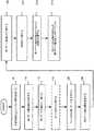
図1は、本発明の趣旨に沿った実装におけるダブルゲートMOSFETを製造するプロセスの一例を示す図である。図2ないし図4は、図1に記載したプロセスによって製造したMOSFETの典型的な断面図の一例を示す図である。 FIG. 1 is a diagram showing an example of a process for manufacturing a double-gate MOSFET in a mounting according to the spirit of the present invention. 2 to 4 are views showing examples of typical cross-sectional views of MOSFETs manufactured by the process shown in FIG.
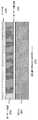
図1および図2を参照して、処理は、シリコン基板200、埋込酸化膜210、およびこの埋込酸化膜210上のシリコン層220を含むSOI(シリコン・オン・インシュレータ)構造から開始してもよい。埋込酸化膜210およびシリコン層220は、従来の方法により基板200上に形成することができる。この埋込酸化膜の厚みは、例えば約100Åから2000Åの範囲としてもよい。シリコン層220の厚みは約200Åから1000Åの範囲としてもよい。フィンを形成するためにシリコン層220が使用されることが、認識されるであろう。 Referring to FIGS. 1 and 2, the processing starts from an SOI (silicon on insulator) structure including a silicon substrate 200, a buried
ゲート酸化膜230はたい積してもよいし、またはシリコン層220上に熱処理により成長させてもよい(ステップ105)。
ゲート酸化膜230は、約5Åから50Åにわたる厚みで形成することができる。代替的に、高誘電率材料( high-K dielectric materials)のような他のゲート絶縁材料を使用してもよい。ある実装においては、ゲート絶縁材料として窒化酸化物を使用してもよい。
第1ゲートを形成すべく、ゲート酸化膜230上にゲート電極層240をたい積することができる(ステップ110)。
ゲート電極240は、多くの材料を使用して形成することができる。ゲート電極240は、例えば金属(例えばタングステン、タンタル、アルミニウム、ニッケル、ルテニウム、ロジウム、パラジウム、プラチナ、チタン、モリブデンなど)、化合物を含む金属(例えば窒化チタン、タンタル窒化物、酸化ルテニウムなど)、またははドープされた半導体(例えば多結晶シリコン、多結晶シリコンゲルマニウムなど)から形成されてもよい。
パターン最適化またはCMP(chemical-mechanical polishing)を促進すべく、任意にカバー層250(またはハードマスク)をゲート電極240上に形成してもよい(ステップ115)。
カバー層250は例えば、窒化ケイ素(SiN)材料または製造プロセス中にゲート電極を保護することができる他の同様の種類の材料を含んでいてもよい。カバー層250は例えば、約30Åから200Åから1000Åにおよぶ厚みで化学蒸着法(CVD)によってたい積してもよい。The
The
A
The
A cover layer 250 (or hard mask) may optionally be formed on the
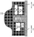
フィン220および第1ゲート230/240は、従来のフォトリソグラフィ技術(例えば電子ビーム(EB)リソグラフィ)によってパターン化することができる(ステップ120)。その後、周知のエッチング技術を使用して、フィン220および第1ゲート230をエッチングしてもよい(ステップ120)。その結果、図3に示した構造300となる。構造300中のフィン220および第1ゲート230の幅は、約50Åから500Åであり得る。 The
フィン220および第1ゲート230を形成した後、第2ゲートを形成することができる。第2ゲート酸化膜410は、図4に記載するように、たい積してもよいし、熱処理により成長させてもよい(ステップ125)。
ゲート酸化膜410は、約5Åから50Åの厚みになるようにたい積または成長させてもよい。
代替的に、他のゲート絶縁材料を使用してもよい。例えば高誘電率材料( high-K dielectric materials)のいずれをゲート絶縁材料として使用してもよい。
第2ゲートを形成すべく、ゲート酸化膜410上に第2ゲート電極層420をたい積することができる(ステップ130)。
第1ゲート電極240と同様、多くの材料を使用して第2ゲート電極を形成することができる。
その結果、この構造400においては、2つのゲート(すなわちゲート240、420)がそれぞれフィン・チャネルを制御できるようになる。
トランジスタ(例えば、ソースおよびドレイン領域を形成する)、コンタクト、相互接続、およびダブルゲートMOSFETについての層間絶縁膜(inter-level dielectrics)を形成するために、従来のMOSFET製造プロセスを使用してもよい。After forming the
The
Alternatively, other gate insulating materials may be used. For example, any of high-K dielectric materials may be used as the gate insulating material.
A second
Similar to the
As a result, in this
Conventional MOSFET fabrication processes may be used to form inter-level dielectrics for transistors (eg, forming source and drain regions), contacts, interconnects, and double-gate MOSFETs. .
図5は、本発明の趣旨に沿った実装におけるトリプルゲートMOSFETを製造する方法の一例を示す図である。図6ないし図8は、図5に記載されたプロセスにしたがって製造されたトリプルゲートMOSFETの断面図の一例を示している。処理は、上述の図1に関するステップ105ないし130を実行することによって開始することができる。
ゲート電極層420をたい積した後、図6に示すように、層間絶縁膜(ILD)610を、第2ゲート電極層410上にたい積してもよい(ステップ505)。
ILD610は例えば、テトラエトキシシラン(TEOS)または他の同様の種類の材料を含んでいてもよい。
ILD610の厚みは、第2ゲート電極420の高さより上に伸びるようになっていてもよい。FIG. 5 is a diagram showing an example of a method of manufacturing a triple gate MOSFET in the mounting according to the spirit of the present invention. 6 to 8 show an example of a cross-sectional view of a triple gate MOSFET manufactured according to the process described in FIG. The process can begin by performing steps 105-130 with respect to FIG. 1 above.
After depositing the
The ILD 610 may include, for example, tetraethoxysilane (TEOS) or other similar types of materials.
The thickness of the ILD 610 may extend above the height of the
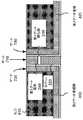
その後、図7に示したように、第1ゲート電極240が露出するようにウェーハ表面をプレーナ化すべく、化学的機械的研磨(CMP)またはその他のこれに類似する技術を実行してもよい。これにより、2つの独立のゲート構造、すなわちゲート720および730を形成すべく、第2ゲート電極420を分割することができる。
この構成に基づいて、トリプルゲートMOSFETを形成することができる。このトリプルゲートMOSFETにおいては、第1ゲート電極240が第3ゲート710として機能する。ゲート710ないし730は各々独立してフィン220を制御できる。
図8に示すように、ゲート710に対する容量結合を減少すべく、既知の技術を使用して、ゲート720および730をエッチバック(etched back)してもよい(ステップ515)。
トランジスタ(例えば、ソースおよびドレイン領域を形成する)、コンタクト、相互接続、およびトリプルゲートMOSFETについての層間絶縁膜(inter-level dielectrics)を形成するために、従来のMOSFET製造プロセスを使用してもよい。Thereafter, as shown in FIG. 7, chemical mechanical polishing (CMP) or other similar techniques may be performed to planarize the wafer surface such that the
Based on this configuration, a triple gate MOSFET can be formed. In this triple gate MOSFET, the
As shown in FIG. 8,
Conventional MOSFET fabrication processes may be used to form inter-level dielectrics for transistors (eg, forming source and drain regions), contacts, interconnects, and triple gate MOSFETs. .
移動度は、トランジスタの性能を改善する重要な特性である。フィルム中における負荷(または応力)の状態が移動度に影響し得る。例えば、圧縮応力は正孔移動度を改善するが、引張歪みは電子移動度を高める。 Mobility is an important characteristic that improves transistor performance. The state of load (or stress) in the film can affect mobility. For example, compressive stress improves hole mobility, while tensile strain increases electron mobility.
図9は、フィンに移動度を加えるための構造の一例を示す図である。この図に示すように、半導体基板上にシリコン層を形成することによってフィン構造910を形成してもよい。
本発明における実装の一例においては、半導体基板は、埋込酸化膜のような、100Åから2000Åにおよぶ厚みで形成された絶縁層を含むSOI構造であり得る。埋込酸化膜を有する半導体基板を形成するための処理は、集積回路製造技術において周知である。FIG. 9 is a diagram illustrating an example of a structure for adding mobility to the fin. As shown in this figure, the
In one example of implementation in the present invention, the semiconductor substrate may be an SOI structure including an insulating layer formed with a thickness ranging from 100 to 2000 mm, such as a buried oxide film. Processing for forming a semiconductor substrate having a buried oxide film is well known in integrated circuit manufacturing technology.
その後、高い応力が与えられたフィルム(以下、「キャップ層」と呼ぶ)920を、フィン構造910上に形成することができる。
ある実装の一例においては、キャップ層920は、約100Åから1000Åの厚みで、例えば窒化物ベースの材料から形成することができる。代替的に他の材料を使用してもよい。
フィン910が移動度を改善すべく歪みを与えるように、フィン910がエッチングされた後もキャップ層920は残っている。A high stressed film (hereinafter referred to as “cap layer”) 920 can then be formed on the
In one example implementation, the cap layer 920 can be formed from about 100 to 1000 inches thick, for example, from a nitride-based material. Alternatively, other materials may be used.
The cap layer 920 remains after the
図10ないし図12は、薄いフィン本体構造を含むように製造したMOSFETのの断面図の一例を示す図である。
図10に示すように、ソース領域1010、ドレイン領域1020、およびフィン構造1030は、従来の製造技術によって形成することができる。
例えば、SOI構造は、半導体基板上に形成された絶縁層(例えば埋込酸化膜)を含んでいてもよい。シリコンフィルムを、SOI構造上に形成してもよい。ハードマスク(例えば二酸化ケイ素)をシリコンフィルム上にたい積してもよい。
その後、フィン構造1030は、例えば電子ビームリソグラフィおよびエッチングによって形成することができる。その後、ソースおよびドレイン領域1010、1020を同様の方法で形成することができる。10 to 12 are views showing an example of a cross-sectional view of a MOSFET manufactured to include a thin fin body structure.
As shown in FIG. 10, the source region 1010, the drain region 1020, and the fin structure 1030 can be formed by conventional manufacturing techniques.
For example, the SOI structure may include an insulating layer (for example, a buried oxide film) formed on a semiconductor substrate. A silicon film may be formed on the SOI structure. A hard mask (eg, silicon dioxide) may be deposited on the silicon film.
Thereafter, the fin structure 1030 can be formed, for example, by electron beam lithography and etching. Thereafter, source and drain regions 1010, 1020 can be formed in a similar manner.
一旦ソース領域1010、ドレイン領域1020、およびフィン構造1030が形成されれば、図11に示すように、ソース領域1010およびドレイン領域1020を保護マスクで覆うことができる。窒化ケイ素ベースの材料のような多くの材料を保護マスクに使用することができる。その後、図12に示すように、薄いフィン構造1230を形成すべく、保護されていないフィン構造1030の厚みを減少させてもよい。
このようにフィン構造1030を薄くするために、エッチングまたは他の著名な技術を使用することができる。Once the source region 1010, the drain region 1020, and the fin structure 1030 are formed, the source region 1010 and the drain region 1020 can be covered with a protective mask as shown in FIG. Many materials can be used for the protective mask, such as silicon nitride based materials. Thereafter, as shown in FIG. 12, the thickness of the unprotected fin structure 1030 may be reduced to form a thin fin structure 1230.
Etching or other prominent techniques can be used to thin the fin structure 1030 in this manner.
本発明の趣旨に沿った実装は、ダブルゲートとトリプルゲートのFinFETデバイスを提供する。従来の設計と異なり、FinFET中のゲートはそれぞれ独立してフィン・チャネルを制御できる。 Implementations consistent with the spirit of the invention provide double gate and triple gate FinFET devices. Unlike conventional designs, each gate in the FinFET can control the fin channel independently.
上述した本発明の典型的な実施形態の記載は、説明を提供するが、網羅的なものではなく、本発明が開示された正確な形式に制限されるように意図していない。上記教示に照らした変更例や変形例が可能であるとともに、本発明の実施することによって変更例や変形例を得ることができる。
例えば、上記記載においては、本発明についてよく理解できるように、特定の材料、構造、化学薬品、プロセス等のような多数の特定の詳細を記載している。
しかしながら、特にここに記載した詳細によることなく、本発明を実行することができる。その他、不必要に本発明の内容を不明瞭にしないように、周知のプロセス構造は詳細に記載していない。
本発明を実行する際に、従来のたい積技術、フォトリソグラフィ技術、およびエッチング技術を使用してもよい。なお、このような技術の詳細についてはここでは詳述していない。The above description of exemplary embodiments of the present invention provides description, but is not exhaustive and is not intended to limit the invention to the precise form disclosed. Modifications and modifications in light of the above teachings are possible, and modifications and modifications can be obtained by implementing the present invention.
For example, in the above description, numerous specific details are set forth such as specific materials, structures, chemicals, processes, etc., in order to provide a thorough understanding of the present invention.
However, the invention can be practiced without the specific details set forth herein. In other instances, well known process structures have not been described in detail in order not to unnecessarily obscure the contents of the invention.
In practicing the present invention, conventional deposition techniques, photolithography techniques, and etching techniques may be used. Note that details of such a technique are not described in detail here.
図1ないし図5に関する一連のステップ行為が記載されているが、ステップの順序は、本発明によるその他の実装において変更することができる。また、独立のステップを平行して実行してもよい。
明示がない場合には、本出願の詳細な説明の中で使用されるどの要素、行為またステップも本発明に重要または本質的なものとして解釈すべきではない。
さらにここに使用される、「1つの(a)」と言う言葉は、1つ以上のものを含むように意図される。1つのものを示すような場合には「1つの(one)」又はこれに類する言葉を使用している。本発明の範囲は、請求の範囲およびこれらの均等物によって定義される。Although a series of step actions are described with respect to FIGS. 1-5, the order of the steps can be changed in other implementations according to the invention. Independent steps may be executed in parallel.
If not expressly stated, any element, act or step used in the detailed description of this application should not be construed as critical or essential to the invention.
Further, as used herein, the term “a (a)” is intended to include one or more. When referring to one thing, “one” or similar words are used. The scope of the present invention is defined by the claims and their equivalents.
Claims (9)
Translated fromJapanese前記フィン構造および前記第1ゲート構造を囲む、第2ゲート構造を形成し、もって前記第1ゲート構造および前記第2ゲート構造が前記フィン構造を独立して制御することができるようにするステップと、を含む、
MOS電界効果トランジスタ(MOSFET)中のゲートを形成する方法。A fin structure on topof the fin structure, comprising the steps of a width to forma width substantially the first gate structure is the same of the fin structure,
Forming a second gate structure surrounding the fin structure and the first gate structure, so that the first gate structure and the second gate structure can independently control the fin structure; ,including,
A method of forming a gate in a MOS field effect transistor (MOSFET).
半導体基板上に形成される絶縁層上にシリコン層を形成するステップを含む、請求項1記載の方法。Forming the fin structureand the first gate structure comprises:
The method of claim 1, comprising forming a silicon layer on an insulating layer formed on a semiconductor substrate.
前記半導体基板上に形成される絶縁層上に形成された前記シリコン層上に絶縁層を形成するステップと、
この絶縁層上にゲート電極層をたい積するステップと、
前記ゲート電極層をパターン化するステップと、を更に含む、請求項2記載の方法。Forming asaid fin structureandthe first gate structure,
Forming an insulating layer on the silicon layerformed on the insulating layer formed on the semiconductor substrate;
Depositing a gate electrode layer on the insulating layer;
The method of claim 2,further comprising: patterning the gate electrode layer.
前記フィン構造および前記第1ゲート構造を囲むように第2絶縁層を形成するステップと、
前記第2絶縁層上に第2ゲート電極層をたい積するステップと、
前記第2ゲート電極層をパターン化するステップと、を含む、請求項1記載の方法。Forming the second gate structure comprises:
Forming a second insulating layer so as to surround the fin structure and the first gate structure;
Depositing a second gate electrode layer on the second insulating layer;
The method of claim 1, comprising patterning the second gate electrode layer.
前記フィンおよび前記第1ゲートを囲む、第2ゲートを形成するステップと、
前記第1ゲートを露出させるべく、前記第2ゲートの一部を除去し、これにより前記第2ゲートを分離したゲート構造である第3ゲート及び第4ゲートとして分割し、もって前記第1ゲート、前記第3ゲートおよび前記第4ゲートが前記フィンを独立して制御することができるようにするステップと、を含む、
MOS電界効果トランジスタ(MOSFET)中のゲートを形成する方法。And the fins, on the fin, a stepof its width to form a firstgatehaving a width substantially identical to the fin structure,
Forming a second gate surrounding the fin and the first gate;
In order to expose the first gate, a part of the second gate is removed, whereby the second gate is divided into a third gate and a fourth gate, which are separated gate structures, and thus the first gate, Allowing the third gate and the fourth gate to independently control the fins;
A method of forming a gate in a MOS field effect transistor (MOSFET).
半導体基板上に形成される絶縁層上にシリコン層を形成するステップを含む、請求項6記載の方法。Formingthe finand the first gate comprises:
The method of claim 6, comprising forming a silicon layer on an insulating layer formed on the semiconductor substrate.
前記半導体基板上に形成される絶縁層上に形成された前記シリコン層上に絶縁材料を形成するステップと、
この絶縁材料上にゲート電極層をたい積するステップと、を更に含む、請求項7記載の方法。Forming asaid said fin first gate,
Forming an insulating material on the silicon layerformed on the insulating layer formed on the semiconductor substrate;
8. The method of claim 7,further comprising depositing a gate electrode layer on the insulating material.
前記フィンおよび前記第1ゲートを囲むように第2絶縁材料を形成するステップと、
前記第2絶縁材料上に第2ゲート電極層をたい積するステップと、を含む、請求項6記載の方法。Forming the second gate comprises:
Forming a second insulating material so as to surround the fin and the first gate;
And depositing a second gate electrode layer on the second insulating material.
Applications Claiming Priority (3)
| Application Number | Priority Date | Filing Date | Title |
|---|---|---|---|
| US10/274,961US8222680B2 (en) | 2002-10-22 | 2002-10-22 | Double and triple gate MOSFET devices and methods for making same |
| US10/274,961 | 2002-10-22 | ||
| PCT/US2003/032660WO2004038808A2 (en) | 2002-10-22 | 2003-10-14 | Double and triple gate mosfet devices and methods for making same |
Publications (2)
| Publication Number | Publication Date |
|---|---|
| JP2006504267A JP2006504267A (en) | 2006-02-02 |
| JP5057649B2true JP5057649B2 (en) | 2012-10-24 |
Family
ID=32093187
Family Applications (1)
| Application Number | Title | Priority Date | Filing Date |
|---|---|---|---|
| JP2004546872AExpired - LifetimeJP5057649B2 (en) | 2002-10-22 | 2003-10-14 | Double and triple gate MOSFET devices and methods of manufacturing these MOSFET devices |
Country Status (9)
| Country | Link |
|---|---|
| US (2) | US8222680B2 (en) |
| EP (1) | EP1554758B1 (en) |
| JP (1) | JP5057649B2 (en) |
| KR (1) | KR101060279B1 (en) |
| CN (1) | CN100472810C (en) |
| AU (1) | AU2003282848A1 (en) |
| DE (1) | DE60336492D1 (en) |
| TW (1) | TWI315911B (en) |
| WO (1) | WO2004038808A2 (en) |
Families Citing this family (70)
| Publication number | Priority date | Publication date | Assignee | Title |
|---|---|---|---|---|
| US8222680B2 (en) | 2002-10-22 | 2012-07-17 | Advanced Micro Devices, Inc. | Double and triple gate MOSFET devices and methods for making same |
| US7388259B2 (en)* | 2002-11-25 | 2008-06-17 | International Business Machines Corporation | Strained finFET CMOS device structures |
| US6855990B2 (en)* | 2002-11-26 | 2005-02-15 | Taiwan Semiconductor Manufacturing Co., Ltd | Strained-channel multiple-gate transistor |
| US7148526B1 (en) | 2003-01-23 | 2006-12-12 | Advanced Micro Devices, Inc. | Germanium MOSFET devices and methods for making same |
| US6855606B2 (en)* | 2003-02-20 | 2005-02-15 | Taiwan Semiconductor Manufacturing Company, Ltd. | Semiconductor nano-rod devices |
| JP4632046B2 (en)* | 2003-04-09 | 2011-02-16 | 日本電気株式会社 | Vertical MISFET semiconductor device having high mobility silicon channel |
| US7074656B2 (en)* | 2003-04-29 | 2006-07-11 | Taiwan Semiconductor Manufacturing Company, Ltd. | Doping of semiconductor fin devices |
| US20040266115A1 (en)* | 2003-06-25 | 2004-12-30 | Bor-Wen Chan | Method of making a gate electrode on a semiconductor device |
| US6909151B2 (en) | 2003-06-27 | 2005-06-21 | Intel Corporation | Nonplanar device with stress incorporation layer and method of fabrication |
| US7005330B2 (en)* | 2003-06-27 | 2006-02-28 | Taiwan Semiconductor Manufacturing Company, Ltd. | Structure and method for forming the gate electrode in a multiple-gate transistor |
| US7078742B2 (en)* | 2003-07-25 | 2006-07-18 | Taiwan Semiconductor Manufacturing Co., Ltd. | Strained-channel semiconductor structure and method of fabricating the same |
| US7301206B2 (en)* | 2003-08-01 | 2007-11-27 | Taiwan Semiconductor Manufacturing Company, Ltd. | Semiconductor-on-insulator SRAM configured using partially-depleted and fully-depleted transistors |
| US6835618B1 (en) | 2003-08-05 | 2004-12-28 | Advanced Micro Devices, Inc. | Epitaxially grown fin for FinFET |
| US7196374B1 (en)* | 2003-09-03 | 2007-03-27 | Advanced Micro Devices, Inc. | Doped structure for FinFET devices |
| JP4216676B2 (en)* | 2003-09-08 | 2009-01-28 | 株式会社東芝 | Semiconductor device |
| US7888201B2 (en)* | 2003-11-04 | 2011-02-15 | Taiwan Semiconductor Manufacturing Company, Ltd. | Semiconductor-on-insulator SRAM configured using partially-depleted and fully-depleted transistors |
| KR100552058B1 (en)* | 2004-01-06 | 2006-02-20 | 삼성전자주식회사 | Semiconductor device having field effect transistor and manufacturing method thereof |
| US7056773B2 (en)* | 2004-04-28 | 2006-06-06 | International Business Machines Corporation | Backgated FinFET having different oxide thicknesses |
| US7452778B2 (en)* | 2004-06-10 | 2008-11-18 | Taiwan Semiconductor Manufacturing Company, Ltd. | Semiconductor nano-wire devices and methods of fabrication |
| KR100541657B1 (en)* | 2004-06-29 | 2006-01-11 | 삼성전자주식회사 | Multi-gate transistor fabrication method and multi-gate transistor fabricated thereby |
| US7042009B2 (en) | 2004-06-30 | 2006-05-09 | Intel Corporation | High mobility tri-gate devices and methods of fabrication |
| US8669145B2 (en) | 2004-06-30 | 2014-03-11 | International Business Machines Corporation | Method and structure for strained FinFET devices |
| US7348284B2 (en) | 2004-08-10 | 2008-03-25 | Intel Corporation | Non-planar pMOS structure with a strained channel region and an integrated strained CMOS flow |
| US7388257B2 (en)* | 2004-09-01 | 2008-06-17 | International Business Machines Corporation | Multi-gate device with high k dielectric for channel top surface |
| US7422946B2 (en) | 2004-09-29 | 2008-09-09 | Intel Corporation | Independently accessed double-gate and tri-gate transistors in same process flow |
| US20060086977A1 (en) | 2004-10-25 | 2006-04-27 | Uday Shah | Nonplanar device with thinned lower body portion and method of fabrication |
| US7518196B2 (en) | 2005-02-23 | 2009-04-14 | Intel Corporation | Field effect transistor with narrow bandgap source and drain regions and method of fabrication |
| US7170772B1 (en) | 2005-07-29 | 2007-01-30 | International Business Machines Corporation | Apparatus and method for dynamic control of double gate devices |
| US7402875B2 (en) | 2005-08-17 | 2008-07-22 | Intel Corporation | Lateral undercut of metal gate in SOI device |
| US7341916B2 (en)* | 2005-11-10 | 2008-03-11 | Atmel Corporation | Self-aligned nanometer-level transistor defined without lithography |
| US7326976B2 (en)* | 2005-11-15 | 2008-02-05 | International Business Machines Corporation | Corner dominated trigate field effect transistor |
| US20080054361A1 (en)* | 2006-08-30 | 2008-03-06 | Infineon Technologies Ag | Method and apparatus for reducing flicker noise in a semiconductor device |
| US8217435B2 (en)* | 2006-12-22 | 2012-07-10 | Intel Corporation | Floating body memory cell having gates favoring different conductivity type regions |
| US8173532B2 (en)* | 2007-07-30 | 2012-05-08 | International Business Machines Corporation | Semiconductor transistors having reduced distances between gate electrode regions |
| JP5285947B2 (en)* | 2008-04-11 | 2013-09-11 | 株式会社東芝 | Semiconductor device and manufacturing method thereof |
| CN102361011B (en)* | 2008-06-11 | 2016-06-22 | 美格纳半导体有限会社 | The method forming the grid of semiconductor device |
| US8362566B2 (en) | 2008-06-23 | 2013-01-29 | Intel Corporation | Stress in trigate devices using complimentary gate fill materials |
| US8796777B2 (en)* | 2009-09-02 | 2014-08-05 | Qualcomm Incorporated | Fin-type device system and method |
| KR101056229B1 (en) | 2009-10-12 | 2011-08-11 | 삼성모바일디스플레이주식회사 | An organic light emitting display device comprising a thin film transistor, a method of manufacturing the same, and a thin film transistor |
| US8729627B2 (en)* | 2010-05-14 | 2014-05-20 | Taiwan Semiconductor Manufacturing Company, Ltd. | Strained channel integrated circuit devices |
| US8368146B2 (en) | 2010-06-15 | 2013-02-05 | International Business Machines Corporation | FinFET devices |
| US8021950B1 (en)* | 2010-10-26 | 2011-09-20 | International Business Machines Corporation | Semiconductor wafer processing method that allows device regions to be selectively annealed following back end of the line (BEOL) metal wiring layer formation |
| US8889494B2 (en) | 2010-12-29 | 2014-11-18 | Globalfoundries Singapore Pte. Ltd. | Finfet |
| US9214529B2 (en)* | 2011-03-14 | 2015-12-15 | Globalfoundries Inc. | Fin Fet device with independent control gate |
| US9293584B2 (en)* | 2011-11-02 | 2016-03-22 | Broadcom Corporation | FinFET devices |
| US8604518B2 (en) | 2011-11-30 | 2013-12-10 | Taiwan Semiconductor Manufacturing Company, Ltd. | Split-channel transistor and methods for forming the same |
| US8723223B2 (en) | 2011-11-30 | 2014-05-13 | Taiwan Semiconductor Manufacturing Company, Ltd. | Hybrid Fin field-effect transistors |
| US8907431B2 (en)* | 2011-12-16 | 2014-12-09 | Taiwan Semiconductor Manufacturing Company, Ltd. | FinFETs with multiple threshold voltages |
| WO2013095550A1 (en)* | 2011-12-22 | 2013-06-27 | Intel Corporation | Semiconductor device having a necked semiconductor body and method of forming semiconductor bodies of varying width |
| KR101878744B1 (en) | 2012-01-03 | 2018-07-16 | 삼성전자주식회사 | Oxide transistor for high voltage and method of manufacturing the same |
| US9029863B2 (en)* | 2012-04-20 | 2015-05-12 | Semiconductor Energy Laboratory Co., Ltd. | Semiconductor device and method for manufacturing the same |
| CN103383965B (en)* | 2012-05-04 | 2016-01-20 | 台湾积体电路制造股份有限公司 | Mixing fin formula field effect transistor |
| US9817928B2 (en) | 2012-08-31 | 2017-11-14 | Synopsys, Inc. | Latch-up suppression and substrate noise coupling reduction through a substrate back-tie for 3D integrated circuits |
| US9190346B2 (en) | 2012-08-31 | 2015-11-17 | Synopsys, Inc. | Latch-up suppression and substrate noise coupling reduction through a substrate back-tie for 3D integrated circuits |
| CN103839810B (en)* | 2012-11-21 | 2017-02-22 | 中芯国际集成电路制造(上海)有限公司 | Fin field effect transistor chip and manufacturing method thereof |
| US8847324B2 (en) | 2012-12-17 | 2014-09-30 | Synopsys, Inc. | Increasing ION /IOFF ratio in FinFETs and nano-wires |
| US9379018B2 (en) | 2012-12-17 | 2016-06-28 | Synopsys, Inc. | Increasing Ion/Ioff ratio in FinFETs and nano-wires |
| US9634000B2 (en)* | 2013-03-14 | 2017-04-25 | International Business Machines Corporation | Partially isolated fin-shaped field effect transistors |
| US9257536B2 (en) | 2013-04-22 | 2016-02-09 | Globalfoundries Inc. | FinFET with crystalline insulator |
| KR102066848B1 (en) | 2013-06-24 | 2020-01-16 | 삼성전자 주식회사 | Semiconductor device and method for fabricating the same |
| KR20150020848A (en)* | 2013-08-19 | 2015-02-27 | 에스케이하이닉스 주식회사 | PMOS Transistor Improved Current-drivability With Vertical Channel, Variable Resistive Memory Device Including the same And Method of Manufacturing PMOS Transistor |
| CN105845725B (en) | 2015-01-12 | 2019-01-22 | 中芯国际集成电路制造(上海)有限公司 | A semiconductor device and its manufacturing method and electronic device |
| KR102251061B1 (en) | 2015-05-04 | 2021-05-14 | 삼성전자주식회사 | Semiconductor devices having strained channel and manufacturing method thereof |
| TWI574402B (en) | 2016-04-28 | 2017-03-11 | 國立交通大學 | Field effect transistor structure |
| US9953876B1 (en) | 2016-09-30 | 2018-04-24 | Globalfoundries Inc. | Method of forming a semiconductor device structure and semiconductor device structure |
| CN106898553A (en)* | 2017-03-16 | 2017-06-27 | 北京大学 | A kind of fin formula field effect transistor and preparation method thereof |
| CN106952959B (en)* | 2017-03-16 | 2020-04-03 | 北京大学 | A kind of germanium silicon channel fin field effect transistor and preparation method thereof |
| US10297672B2 (en) | 2017-07-13 | 2019-05-21 | Globalfoundries Inc. | Triple gate technology for 14 nanometer and onwards |
| DE102018126911A1 (en) | 2017-11-30 | 2019-06-06 | Intel Corporation | Gate cut and fin trim isolation for advanced integrated circuit structure fabrication |
| KR20230006054A (en)* | 2017-11-30 | 2023-01-10 | 인텔 코포레이션 | Fin patterning for advanced integrated circuit structure fabrication |
Family Cites Families (28)
| Publication number | Priority date | Publication date | Assignee | Title |
|---|---|---|---|---|
| JP2582794B2 (en) | 1987-08-10 | 1997-02-19 | 株式会社東芝 | Semiconductor device and manufacturing method thereof |
| JPH03250770A (en) | 1990-02-28 | 1991-11-08 | Sony Corp | Semiconductor device |
| EP0623963A1 (en) | 1993-05-06 | 1994-11-09 | Siemens Aktiengesellschaft | MOSFET on SOI substrate |
| JPH08204191A (en) | 1995-01-20 | 1996-08-09 | Sony Corp | Field effect transistor and method of manufacturing the same |
| JP3261306B2 (en) | 1996-04-04 | 2002-02-25 | シャープ株式会社 | Semiconductor memory device and method of manufacturing the same |
| US6288431B1 (en)* | 1997-04-04 | 2001-09-11 | Nippon Steel Corporation | Semiconductor device and a method of manufacturing the same |
| DE10012112C2 (en)* | 2000-03-13 | 2002-01-10 | Infineon Technologies Ag | Bridge field effect transistor and method for producing a bridge field effect transistor |
| WO2001069689A1 (en) | 2000-03-16 | 2001-09-20 | Max Roth | Energy element with photovoltaic layer |
| US6483156B1 (en) | 2000-03-16 | 2002-11-19 | International Business Machines Corporation | Double planar gated SOI MOSFET structure |
| JP4443008B2 (en)* | 2000-06-30 | 2010-03-31 | 富士通株式会社 | Semiconductor device and manufacturing method thereof |
| US6342410B1 (en)* | 2000-07-10 | 2002-01-29 | Advanced Micro Devices, Inc. | Fabrication of a field effect transistor with three sided gate structure on semiconductor on insulator |
| JP4044276B2 (en)* | 2000-09-28 | 2008-02-06 | 株式会社東芝 | Semiconductor device and manufacturing method thereof |
| US6413802B1 (en)* | 2000-10-23 | 2002-07-02 | The Regents Of The University Of California | Finfet transistor structures having a double gate channel extending vertically from a substrate and methods of manufacture |
| US6359311B1 (en) | 2001-01-17 | 2002-03-19 | Taiwan Semiconductor Manufacturing Co., Ltd. | Quasi-surrounding gate and a method of fabricating a silicon-on-insulator semiconductor device with the same |
| US6635923B2 (en) | 2001-05-24 | 2003-10-21 | International Business Machines Corporation | Damascene double-gate MOSFET with vertical channel regions |
| KR100431489B1 (en)* | 2001-09-04 | 2004-05-12 | 한국과학기술원 | Flash memory element and manufacturing method |
| US6433609B1 (en) | 2001-11-19 | 2002-08-13 | International Business Machines Corporation | Double-gate low power SOI active clamp network for single power supply and multiple power supply applications |
| US6800905B2 (en) | 2001-12-14 | 2004-10-05 | International Business Machines Corporation | Implanted asymmetric doped polysilicon gate FinFET |
| US6657252B2 (en) | 2002-03-19 | 2003-12-02 | International Business Machines Corporation | FinFET CMOS with NVRAM capability |
| US6974729B2 (en)* | 2002-07-16 | 2005-12-13 | Interuniversitair Microelektronica Centrum (Imec) | Integrated semiconductor fin device and a method for manufacturing such device |
| US6770516B2 (en)* | 2002-09-05 | 2004-08-03 | Taiwan Semiconductor Manufacturing Company | Method of forming an N channel and P channel FINFET device on the same semiconductor substrate |
| US6833588B2 (en) | 2002-10-22 | 2004-12-21 | Advanced Micro Devices, Inc. | Semiconductor device having a U-shaped gate structure |
| US8222680B2 (en) | 2002-10-22 | 2012-07-17 | Advanced Micro Devices, Inc. | Double and triple gate MOSFET devices and methods for making same |
| US7214991B2 (en) | 2002-12-06 | 2007-05-08 | Taiwan Semiconductor Manufacturing Co., Ltd. | CMOS inverters configured using multiple-gate transistors |
| US7148526B1 (en) | 2003-01-23 | 2006-12-12 | Advanced Micro Devices, Inc. | Germanium MOSFET devices and methods for making same |
| US7259425B2 (en) | 2003-01-23 | 2007-08-21 | Advanced Micro Devices, Inc. | Tri-gate and gate around MOSFET devices and methods for making same |
| US6812119B1 (en) | 2003-07-08 | 2004-11-02 | Advanced Micro Devices, Inc. | Narrow fins by oxidation in double-gate finfet |
| US6876042B1 (en) | 2003-09-03 | 2005-04-05 | Advanced Micro Devices, Inc. | Additional gate control for a double-gate MOSFET |
- 2002
- 2002-10-22USUS10/274,961patent/US8222680B2/ennot_activeExpired - Lifetime
- 2003
- 2003-10-14EPEP03774843Apatent/EP1554758B1/ennot_activeExpired - Lifetime
- 2003-10-14AUAU2003282848Apatent/AU2003282848A1/ennot_activeAbandoned
- 2003-10-14WOPCT/US2003/032660patent/WO2004038808A2/enactiveApplication Filing
- 2003-10-14JPJP2004546872Apatent/JP5057649B2/ennot_activeExpired - Lifetime
- 2003-10-14DEDE60336492Tpatent/DE60336492D1/ennot_activeExpired - Lifetime
- 2003-10-14KRKR1020057006904Apatent/KR101060279B1/ennot_activeExpired - Lifetime
- 2003-10-14CNCNB200380101958XApatent/CN100472810C/ennot_activeExpired - Lifetime
- 2003-10-21TWTW092129118Apatent/TWI315911B/ennot_activeIP Right Cessation
- 2012
- 2012-06-14USUS13/523,603patent/US8580660B2/ennot_activeExpired - Lifetime
Also Published As
| Publication number | Publication date |
|---|---|
| EP1554758B1 (en) | 2011-03-23 |
| WO2004038808A2 (en) | 2004-05-06 |
| US8580660B2 (en) | 2013-11-12 |
| CN1708858A (en) | 2005-12-14 |
| TWI315911B (en) | 2009-10-11 |
| US20120252193A1 (en) | 2012-10-04 |
| EP1554758A2 (en) | 2005-07-20 |
| AU2003282848A1 (en) | 2004-05-13 |
| US20040075122A1 (en) | 2004-04-22 |
| CN100472810C (en) | 2009-03-25 |
| DE60336492D1 (en) | 2011-05-05 |
| KR101060279B1 (en) | 2011-08-30 |
| WO2004038808A3 (en) | 2004-06-10 |
| JP2006504267A (en) | 2006-02-02 |
| KR20050047556A (en) | 2005-05-20 |
| TW200414539A (en) | 2004-08-01 |
| US8222680B2 (en) | 2012-07-17 |
Similar Documents
| Publication | Publication Date | Title |
|---|---|---|
| JP5057649B2 (en) | Double and triple gate MOSFET devices and methods of manufacturing these MOSFET devices | |
| JP4795932B2 (en) | Tri-gate and gate-around MOSFET devices and methods of manufacturing these MOSFET devices | |
| US7781810B1 (en) | Germanium MOSFET devices and methods for making same | |
| JP5009611B2 (en) | Method for forming a structure in a FINFET device | |
| US7388259B2 (en) | Strained finFET CMOS device structures | |
| EP1565931B1 (en) | Strained finfet cmos device structures | |
| JP5409997B2 (en) | Method for forming a gate in a FinFET device and method for manufacturing a semiconductor device | |
| KR101112046B1 (en) | Self aligned damascene gate | |
| US8008136B2 (en) | Fully silicided gate structure for FinFET devices | |
| JP2006505950A (en) | Double-gate semiconductor device having multiple separated gates | |
| US7041601B1 (en) | Method of manufacturing metal gate MOSFET with strained channel |
Legal Events
| Date | Code | Title | Description |
|---|---|---|---|
| A621 | Written request for application examination | Free format text:JAPANESE INTERMEDIATE CODE: A621 Effective date:20060926 | |
| A977 | Report on retrieval | Free format text:JAPANESE INTERMEDIATE CODE: A971007 Effective date:20091228 | |
| RD03 | Notification of appointment of power of attorney | Free format text:JAPANESE INTERMEDIATE CODE: A7423 Effective date:20100421 | |
| RD05 | Notification of revocation of power of attorney | Free format text:JAPANESE INTERMEDIATE CODE: A7425 Effective date:20100902 | |
| A131 | Notification of reasons for refusal | Free format text:JAPANESE INTERMEDIATE CODE: A131 Effective date:20101006 | |
| A601 | Written request for extension of time | Free format text:JAPANESE INTERMEDIATE CODE: A601 Effective date:20110106 | |
| A602 | Written permission of extension of time | Free format text:JAPANESE INTERMEDIATE CODE: A602 Effective date:20110114 | |
| A521 | Request for written amendment filed | Free format text:JAPANESE INTERMEDIATE CODE: A523 Effective date:20110204 | |
| A02 | Decision of refusal | Free format text:JAPANESE INTERMEDIATE CODE: A02 Effective date:20110302 | |
| A521 | Request for written amendment filed | Free format text:JAPANESE INTERMEDIATE CODE: A523 Effective date:20110630 | |
| A911 | Transfer to examiner for re-examination before appeal (zenchi) | Free format text:JAPANESE INTERMEDIATE CODE: A911 Effective date:20110808 | |
| A912 | Re-examination (zenchi) completed and case transferred to appeal board | Free format text:JAPANESE INTERMEDIATE CODE: A912 Effective date:20110902 | |
| A01 | Written decision to grant a patent or to grant a registration (utility model) | Free format text:JAPANESE INTERMEDIATE CODE: A01 | |
| A61 | First payment of annual fees (during grant procedure) | Free format text:JAPANESE INTERMEDIATE CODE: A61 Effective date:20120731 | |
| FPAY | Renewal fee payment (event date is renewal date of database) | Free format text:PAYMENT UNTIL: 20150810 Year of fee payment:3 | |
| R150 | Certificate of patent or registration of utility model | Ref document number:5057649 Country of ref document:JP Free format text:JAPANESE INTERMEDIATE CODE: R150 Free format text:JAPANESE INTERMEDIATE CODE: R150 | |
| R250 | Receipt of annual fees | Free format text:JAPANESE INTERMEDIATE CODE: R250 | |
| R250 | Receipt of annual fees | Free format text:JAPANESE INTERMEDIATE CODE: R250 | |
| R250 | Receipt of annual fees | Free format text:JAPANESE INTERMEDIATE CODE: R250 | |
| R250 | Receipt of annual fees | Free format text:JAPANESE INTERMEDIATE CODE: R250 | |
| R250 | Receipt of annual fees | Free format text:JAPANESE INTERMEDIATE CODE: R250 | |
| R250 | Receipt of annual fees | Free format text:JAPANESE INTERMEDIATE CODE: R250 | |
| R250 | Receipt of annual fees | Free format text:JAPANESE INTERMEDIATE CODE: R250 | |
| R250 | Receipt of annual fees | Free format text:JAPANESE INTERMEDIATE CODE: R250 | |
| R250 | Receipt of annual fees | Free format text:JAPANESE INTERMEDIATE CODE: R250 | |
| EXPY | Cancellation because of completion of term |