JP5057363B2 - Gas turbine combustor - Google Patents
Gas turbine combustorDownload PDFInfo
- Publication number
- JP5057363B2 JP5057363B2JP2007019466AJP2007019466AJP5057363B2JP 5057363 B2JP5057363 B2JP 5057363B2JP 2007019466 AJP2007019466 AJP 2007019466AJP 2007019466 AJP2007019466 AJP 2007019466AJP 5057363 B2JP5057363 B2JP 5057363B2
- Authority
- JP
- Japan
- Prior art keywords
- fuel injection
- pilot
- main
- staging
- air
- Prior art date
- Legal status (The legal status is an assumption and is not a legal conclusion. Google has not performed a legal analysis and makes no representation as to the accuracy of the status listed.)
- Expired - Fee Related
Links
- 239000000446fuelSubstances0.000claimsdescription171
- 238000002347injectionMethods0.000claimsdescription122
- 239000007924injectionSubstances0.000claimsdescription122
- 238000002485combustion reactionMethods0.000claimsdescription41
- 239000000203mixtureSubstances0.000claimsdescription24
- 239000007789gasSubstances0.000description53
- MWUXSHHQAYIFBG-UHFFFAOYSA-Nnitrogen oxideInorganic materialsO=[N]MWUXSHHQAYIFBG-UHFFFAOYSA-N0.000description19
- 230000000644propagated effectEffects0.000description4
- 239000013626chemical specieSubstances0.000description3
- 238000004519manufacturing processMethods0.000description1
- 230000002093peripheral effectEffects0.000description1
- 230000001902propagating effectEffects0.000description1
- 238000010008shearingMethods0.000description1
Images


Description
Translated fromJapanese本発明は、ガスタービン燃焼器に関し、特に高い低NOx性能を得るためにパイロット燃料噴射部とメイン燃料噴射部から燃料を供給するように構成されたステージング燃料噴射弁を備えたガスタービン燃焼器の着火性の問題を好適に解決するガスタービン燃焼器に関するものである。 The present invention relates to a gas turbine combustor, and more particularly, to a gas turbine combustor including a staging fuel injection valve configured to supply fuel from a pilot fuel injection unit and a main fuel injection unit in order to obtain high low NOx performance. The present invention relates to a gas turbine combustor that suitably solves the problem of ignitability.
排気ガスの窒素酸化物(NOx)を低減することを目的とした航空機用ガスタービン燃焼器としては、既燃焼ガスを形成するためのパイロット燃料噴射弁と、その既燃焼ガス中に混合気を噴射するメイン燃料噴射弁という2種類の燃料噴射弁を持ったステージング型燃焼器の研究が盛んに行われている。これらの燃焼器ではパイロット燃料噴射部を中心に置き、その周りに同心円状にメイン燃料噴射部を配置することが行われている(例えば特許文献1を参照。)。また、航空機用ガスタービン燃焼器ではメンテナンス性を高めるため、点火栓は燃焼器ライナーに設置することが一般的に行われており、この場合、着火時にパイロット燃料噴射部のみから燃料が供給されると、その燃料はメイン燃料噴射部から流出する空気に阻まれ、その結果、点火栓に十分な燃料が到達しない、あるいは、点火によって生じた火種がメイン燃料噴射部の空気に流されパイロットの燃焼領域に到達しないことにより着火性に難があった。安全性が最も重視される航空機用ガスタービンでは高い着火性能が要求されるため、この着火性の問題が低NOxなガスタービン燃焼器の実用化に対し大きな障害の一つとなっている。 As an aircraft gas turbine combustor for the purpose of reducing nitrogen oxides (NOx) in exhaust gas, a pilot fuel injection valve for forming burnt gas and an air-fuel mixture are injected into the burned gas Research on staging combustors having two types of fuel injection valves, ie, main fuel injection valves, has been actively conducted. In these combustors, a pilot fuel injection part is placed at the center, and a main fuel injection part is arranged around the pilot fuel injection part (see, for example, Patent Document 1). In addition, in order to improve maintainability in an aircraft gas turbine combustor, it is common to install a spark plug on a combustor liner. In this case, fuel is supplied only from a pilot fuel injection unit at the time of ignition. Then, the fuel is blocked by the air flowing out from the main fuel injection section, and as a result, sufficient fuel does not reach the spark plug, or the fire type generated by the ignition is flowed into the air of the main fuel injection section and the pilot burns There was difficulty in ignitability by not reaching the area. Aircraft gas turbines where safety is the most important require high ignition performance, and this ignitability problem is one of the major obstacles to the practical application of low-NOx gas turbine combustors.
上述した通り、高い低NOx性能を得るためにパイロット燃料噴射部と、その周りに同芯状に配設されたメイン燃料噴射部とから成るステージング燃料噴射弁を備えたガスタービン用低NOx燃焼器を航空機用ガスタービン燃焼器に使用した場合、着火性能に難がある。
そこで、本発明は、上記実情に鑑み創案されたものであって、高い低NOx性能を得るためにパイロット燃料噴射部とメイン燃料噴射部から燃料を供給するように構成されたステージング燃料噴射弁を備えたガスタービン燃焼器を航空機用ガスタービン燃焼器に使用した場合に生じる着火性の問題を好適に解決するガスタービン燃焼器を提供することを目的とする。As described above, a low-NOx combustor for a gas turbine having a staging fuel injection valve including a pilot fuel injection unit and a main fuel injection unit disposed concentrically around the pilot fuel injection unit in order to obtain high low NOx performance When used in an aircraft gas turbine combustor, the ignition performance is difficult.
Therefore, the present invention was devised in view of the above circumstances, and includes a staging fuel injection valve configured to supply fuel from a pilot fuel injection unit and a main fuel injection unit in order to obtain high low NOx performance. An object of the present invention is to provide a gas turbine combustor that suitably solves the problem of ignitability that occurs when the gas turbine combustor provided is used in an aircraft gas turbine combustor.
前記目的を達成するために、請求項1に記載のガスタービン燃焼器は、燃料と空気が燃焼し燃焼領域を形成する燃焼室と、該燃焼室に混合気を供給する円筒形に形成された複数のステージング燃料噴射弁と、前記燃焼室内の混合気に着火する少なくとも1つの点火栓とを備えたガスタービン燃焼器であって、前記ステージング燃料噴射弁が、パイロット燃料とパイロット空気が混合するパイロット燃料噴射部と、該パイロット燃料噴射部の周りに配設されメイン燃料とメイン空気が混合するメイン燃料噴射部とを有し、前記ステージング燃料噴射弁の少なくとも1つが、前記パイロット燃料噴射部の開口部の中心を円筒形状の中心に対し前記点火栓の側に近接するように偏芯させた偏芯ステージング燃料噴射弁であり、該偏芯ステージング燃料噴射弁のメイン燃料噴射部の開口部が、前記点火栓と離反する側で開口する三日月形状であり、前記燃焼室の形状が環状型であり、前記複数のステージング燃料噴射弁が、前記パイロット燃料噴射部およびメイン燃料噴射部が同芯状に配設されて成る少なくとも1つの同芯ステージング燃料噴射弁と、少なくとも1つの前記偏芯ステージング燃料噴射弁とから成り、前記点火栓の近傍に、前記偏芯ステージング燃料噴射弁が配設されて成ることを特徴とする。
上記ガスタービン燃焼器では、上記構成とすることにより、偏芯ステージング燃料噴射弁のパイロット燃料噴射部から供される混合気は、メイン燃料噴射部から供される空気流よりも燃焼室の点火栓の近傍を直接かつ連続的に流れ、かつ、メイン燃料噴射部の開口部を点火栓と離反する側で開口する三日月形状とすることで、メイン燃料噴射部からの空気に妨げられなくなる。これにより、パイロット燃料噴射部の混合気が点火栓に到達して火種が生じ、火炎が好適に伝播する、あるいは高温ガスや活性化学種が流されることにより、パイロット燃料噴射部下流の再循環領域にパイロット火炎が形成される。その結果、極めて高い着火性能が得られると共に、その安定したパイロット火炎とメイン燃料噴射部から供される混合気により安定した燃焼が成されると同時に、燃焼温度が好適に低下しNOxの生成を好適に抑制するようになる。In order to achieve the object, the gas turbine combustor according to
In the gas turbine combustor, with the above-described configuration, the air-fuel mixture provided from the pilot fuel injection unit of the eccentric staging fuel injection valve is more ignited than the air flow provided from the main fuel injection unit. By making the crescent shape that directly and continuously flows in the vicinity of the, and the opening of the main fuel injection part opens on the side away from the spark plug, the air from the main fuel injection part is not hindered. As a result, the air-fuel mixture in the pilot fuel injection section reaches the spark plug and a fire is generated, the flame propagates favorably, or a high-temperature gas or active chemical species is flowed, so that the recirculation region downstream of the pilot fuel injection section A pilot flame is formed. As a result, extremely high ignition performance is obtained, and stable combustion is achieved by the stable pilot flame and the air-fuel mixture provided from the main fuel injection section, and at the same time, the combustion temperature is suitably reduced to generate NOx . Is suitably suppressed.
また、上記ガスタービン燃焼器では、偏芯ステージング燃料噴射弁を備えたことにより環状型の燃焼室を持つガスタービン燃焼器の着火性能が好適に向上する。Moreover, in the said gas turbine combustor, the ignition performance of the gas turbine combustor which has an annular combustion chamber improves suitably by providing the eccentric staging fuel injection valve.
本発明のガスタービン燃焼器によれば、パイロット燃料噴射部と点火栓の間に流れるメイン燃料噴射部の空気が減少あるいは無くなり、パイロット燃料噴射部の燃料が点火栓に到達して火種が生じて火炎が好適に伝播する、あるいは高温ガスや活性化学種が流されることにより、パイロット燃料噴射部下流の再循環領域にパイロット火炎が形成される。従って、極めて高い着火性能が得られ、低いNOx排出量と高い着火性能を有するパイロット燃料噴射部とメイン燃料噴射部を備えたガスタービン燃焼器を実現することができる。According to the gas turbine combustor of the present invention, the air in the main fuel injection section flowing between the pilot fuel injection section and the spark plug is reduced or eliminated, and the fuel in the pilot fuel injection section reaches the spark plug to generate a fire type. A pilot flame is formed in the recirculation region downstream of the pilot fuel injection section by suitably propagating the flame or flowing a hot gas or active chemical species. Therefore, to obtain a very high ignition performance, it is possible to achieve a low NOx emissions andgas turbine combustor with a pilot fuel injection unit and the main fuel injection unit having a high ignition performance.
以下、図に示す実施の形態により本発明をさらに詳細に説明する。なお、これにより本発明が限定されるものではない。 Hereinafter, the present invention will be described in more detail with reference to embodiments shown in the drawings. Note that the present invention is not limited thereby.
図1は、本発明の実施例1に係るガスタービン燃焼器100を示す要部断面説明図である。
このガスタービン燃焼器100は、着火および保炎等の副燃焼用(以下、「パイロット」という。)の混合気を供給するパイロット燃料噴射部10と、主燃焼用(以下、「メイン」という。)の混合気を供給するメイン燃料噴射部20とから成る偏芯ステージング燃料噴射弁1と、スパークを発生させることにより混合気にパイロット火炎を形成する点火栓30と、そのパイロット火炎により混合気が燃焼する燃焼室40とを具備して構成されている。なお、パイロット燃料噴射部10とメイン燃料噴射部20を一つの組とする偏芯ステージング燃料噴射弁1が、環状等間隔で燃焼室40のドーム壁40bに複数配設されているが、図示の都合上一つの偏芯ステージング燃料噴射弁1しか表されていない。FIG. 1 is an explanatory cross-sectional view of a main part showing a gas turbine combustor 100 according to
The gas turbine combustor 100 is referred to as a pilot
パイロット燃料噴射部10は、パイロット燃料が流れるパイロット燃料供給路11と、パイロット燃料が噴射されるパイロットノズル12と、パイロット空気を供給する第1パイロット空気流路13と、同第2パイロット空気流路14と、パイロット燃料とパイロット空気が混合し燃焼するパイロット燃焼領域15とから成る。 The pilot
また、第1パイロット空気流路13および第2パイロット空気流路14の流路途上にはスワラー16、17が各々配設され、空気流がスワラーを通過することにより旋回空気流が形成される。これにより、パイロットノズル12から噴射されるパイロット燃料は、これらの旋回空気流によってサンドイッチされ、剪断作用および旋回作用を同時に受けながら、これらの空気に対し好適に混合されることになる。従って、パイロット燃焼領域15では、液滴(一部は気化)の燃料と空気が混合され燃焼する。Further, swirlers 16and 17 are respectively disposed in the course of the first pilot
また、詳細については図2を参照しながら後述するが、パイロット燃料噴射部10の中心は、メイン混合流路23の中心に対して点火栓30の側に偏芯し、パイロット燃料噴射部10の開口部はメイン混合流路23の開口部よりも半径方向の外側にあるように構成されている。これにより、パイロット燃料噴射部10から供される混合気は点火栓30に直接かつ連続的に到達し、火種が好適に生じ、そして火炎が好適に伝播する、或いは高温ガスや活性化学種が流されることにより、パイロット燃料領域15にパイロット火炎が形成されることになる。その結果、極めて高い着火性能が得られると共に、その安定したパイロット火炎とメイン燃料噴射部20から供される混合気により安定した燃焼が成されると同時に、燃焼温度が好適に低下しNOxの生成を好適に抑制するようになる。 Although details will be described later with reference to FIG. 2, the center of the pilot
一方、メイン燃料噴射部20は、メイン燃料が流れるメイン燃料供給路21と、メイン燃料が噴射されるメインノズル22と、メイン燃料とメイン空気が混合し混合気を生成するメイン混合流路23とから成る。メインノズル22は、いわゆる渦巻き噴射弁により構成されている。また、後述するように、メイン燃料噴射部20の開口部はパイロット燃料噴射部10の開口部よりも半径方向の内側にあり、メイン燃料噴射部20からの空気流は着火時においてパイロット燃料噴射部10からの混合気を妨げなくなる。 On the other hand, the main
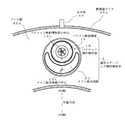
図2は、図1のA−A’断面図である。なお、以下の説明においてメイン混合流路の中心23Cとは、半径方向の対称2等分線がメイン混合流路23の外周線と交わる2点の中点とする。
パイロット燃料噴射部の中心10Cは、メイン混合流路の中心23Cに対し点火栓30の側に偏芯し、その結果、パイロット燃料噴射部10の開口部は半径方向に対し点火栓30に近接するようになる。更に、メイン混合流路23の開口部は、パイロット燃料噴射部10の開口部に比べ半径方向の内側にあり、且つその形状は三日月状となるように構成されている。これにより、パイロット燃料噴射部10の開口部から供される混合気は点火栓30に直接かつ連続的に到達し、火種が好適に生じ、そして火炎が好適に伝播する、或いは高温ガスや活性化学種が流されることにより、パイロット燃料噴射部下流の再循環領域に安定したパイロット火炎が形成されることになる。よって、極めて高い着火性能が得られると共に、その安定したパイロット火炎とメイン燃料噴射部20から供される混合気により安定した燃焼が成されると同時に、燃焼温度が好適に低下しNOxの生成を好適に抑制するようになる。2 is a cross-sectional view taken along line AA ′ of FIG. In the following description, the center 23C of the main mixing channel is defined as a midpoint between two points where the symmetric bisector in the radial direction intersects with the outer peripheral line of the
The center 10C of the pilot fuel injection section is eccentric to the
実施例1に係るガスタービン燃焼器100によれば、パイロット燃料噴射部10とメイン燃料噴射部20とから成る偏芯ステージング燃料噴射弁1を備えたことにより燃焼器における着火性能が向上し、パイロット燃料噴射部10の下流に安定したパイロット火炎が好適に形成され、その安定したパイロット火炎とメイン燃料噴射部20から供される混合気により安定した燃焼が成されると同時に、燃焼温度が好適に低下しNOxの生成を好適に抑制するようになる。 According to the gas turbine combustor 100 according to the first embodiment, since the eccentric staging
図3は、本発明の実施例2に係るガスタービン燃焼器200を示す要部断面説明図である。 FIG. 3 is a cross-sectional explanatory view of a main part showing a
このガスタービン燃焼器200は、メイン燃料噴射部50を除いて上記ガスタービン燃焼器100と同じ構成である。メイン燃料噴射部50は、メイン混合流路53の壁内部にメイン燃料供給路51が形成され、メイン混合流路53の壁面にプレインジェット型の燃料噴射ノズル52が形成されている。 The
図4は、図3のB−B’断面図である。
パイロット燃料噴射部の中心10Cは、メイン混合流路の中心53Cに対し点火栓30の側に偏芯し、その結果、パイロット燃料噴射部10の開口部は半径方向に対し点火栓30に近接するようになる。更に、メイン混合流路53の開口部は、パイロット燃料噴射部10の開口部に比べ半径方向の内側にあり、且つその形状は三日月状となるように構成されている。これにより、パイロット燃料噴射部10の開口部から供される混合気は点火栓30に直接かつ連続的に到達し、火種が好適に生じ、そして火炎が好適に伝播する、或いは高温ガスや活性化学種が流されることにより、パイロット燃料噴射部下流の再循環領域に安定したパイロット火炎が形成されることになる。従って、極めて高い着火性能が得られると共に、その安定したパイロット火炎とメイン混合流路53から供される混合気により安定した燃焼が成されると同時に、燃焼温度が好適に低下しNOxの生成を好適に抑制するようになる。4 is a cross-sectional view taken along the line BB ′ of FIG.
The center 10C of the pilot fuel injection section is eccentric to the
実施例2に係るガスタービン燃焼器200によれば、上記ガスタービン燃焼器100と同様にパイロット燃料噴射部10とメイン燃料噴射部50とから成る偏芯ステージング燃料噴射弁2を備えたことにより燃焼器における着火性能が向上し、パイロット燃焼領域15に安定したパイロット火炎が好適に形成され、その安定したパイロット火炎とメイン混合流路53から供される混合気により安定した燃焼が成されると同時に、燃焼温度が好適に低下しNOxの生成を好適に抑制するようになる。 According to the
図5は、本発明の実施例3に係るガスタービン燃焼器300を示す要部断面説明図である。
このガスタービン燃焼器300は、実施例2に係るガスタービン燃焼器200のパイロット燃料のみを噴射したときの燃焼効率を高めるための工夫を行ったものである。つまり、パイロット燃料のみを噴出するステージにおいて、メインの空気がパイロット燃焼領域に流れ込みパイロット火炎を部分的に消炎させるため、燃焼効率が低下する。この問題を解決するためにメイン混合流路を延長し、パイロットの燃焼が終了した後、合流するようにした。FIG. 5 is an explanatory cross-sectional view of a main part showing a
This
図6は、本発明の実施例4に係るガスタービン燃焼器400を示す要部断面説明図である。
このガスタービン燃焼器400は、偏芯ステージング燃料噴射弁1(又は偏芯ステージング燃料噴射弁2)と、パイロット燃料噴射部とメイン燃料噴射部とが同芯状に配設された同芯ステージング燃料噴射弁3とが混在して、燃焼室のドーム壁40bに環状等間隔に配設されている。なお、偏芯ステージング燃料噴射弁1は同芯ステージング燃料噴射弁3よりも点火栓30に近接して配設されている。これにより、パイロット燃料噴射部10の開口部から供される混合気は点火栓30に直接かつ連続的に到達し、火種が好適に生じ、そして火炎が好適に伝播する、或いは高温ガスや活性化学種が流されることにより、パイロット燃料噴射部下流の再循環領域に安定したパイロット火炎が形成されることになる。従って、極めて高い着火性能が得られると共に、その安定したパイロット火炎とメイン混合流路から供される混合気により安定した燃焼が成されると同時に、燃焼温度が好適に低下しNOxの生成を好適に抑制するようになる。
[参考例]FIG. 6 is a cross-sectional explanatory view of a main part showing a gas turbine combustor 400 according to Embodiment 4 of the present invention.
The gas turbine combustor 400 includes an eccentric staging fuel injection valve 1 (or an eccentric staging fuel injection valve 2), a concentric staging fuel in which a pilot fuel injection unit and a main fuel injection unit are arranged concentrically. The
[Reference example]
図7は、参考例に係るガスタービン燃焼器500を示す要部断面説明図である。
上記本発明の実施例に係るガスタービン燃焼器100,200,300,400は、環状型の燃焼器を有するものであるが、この参考例に係るガスタービン燃焼器500は、ステージング燃料噴射弁として、前述した本発明のガスタービン燃焼器に使用する偏芯ステージング燃料噴射弁のみを筒型の燃焼器に対して適用したものである。FIG. 7 is a cross-sectional explanatory view of a main part showing a
本発明のガスタービン燃焼器は、低NOxの排出が要求されるガスタービン燃焼器を始めとする内燃機関に対し好適に適用することが出来る。 The gas turbine combustor of the present invention can be suitably applied to an internal combustion engine including a gas turbine combustor that requires low NOx emission.
1,2 偏芯ステージング燃料噴射弁
3 同芯ステージング燃料噴射弁
10 パイロット燃料噴射部
11 パイロット燃料供給路
12 パイロットノズル
13 第1パイロット空気流路
14 第2パイロット空気流路
15 パイロット燃焼領域
20,50 メイン燃料噴射部
21,51 メイン燃料供給路
22,52 メインノズル
23,53 メイン混合流路
30 点火栓
40 燃焼室
100,200,300,400,500 ガスタービン燃焼器DESCRIPTION OF
Claims (1)
Translated fromJapanese前記ステージング燃料噴射弁が、パイロット燃料とパイロット空気が混合するパイロット燃料噴射部と、該パイロット燃料噴射部の周りに配設されメイン燃料とメイン空気が混合するメイン燃料噴射部とを有し、
前記ステージング燃料噴射弁の少なくとも1つが、前記パイロット燃料噴射部の開口部の中心を円筒形状の中心に対し前記点火栓の側に近接するように偏芯させた偏芯ステージング燃料噴射弁であり、
該偏芯ステージング燃料噴射弁のメイン燃料噴射部の開口部が、前記点火栓と離反する側で開口する三日月形状であり、
前記燃焼室の形状が環状型であり、
前記複数のステージング燃料噴射弁が、前記パイロット燃料噴射部およびメイン燃料噴射部が同芯状に配設されて成る少なくとも1つの同芯ステージング燃料噴射弁と、少なくとも1つの前記偏芯ステージング燃料噴射弁とから成り、
前記点火栓の近傍に、前記偏芯ステージング燃料噴射弁が配設されて成ることを特徴とするガスタービン燃焼器。A combustion chamber in which fuel and air burn to form a combustion region; aplurality of staging fuel injection valves formed in a cylindrical shape for supplying an air-fuel mixture to the combustion chamber; and at least one for igniting the air-fuel mixture in the combustion chamber A gas turbine combustor comprising a spark plug,
The staging fuel injection valve has a pilot fuel injection unit that mixes pilot fuel and pilot air, and a main fuel injection unit that is disposed around the pilot fuel injection unit and mixes main fuel and main air,
At least one of the staging fuel injection valves is an eccentric staging fuel injection valve in which the center of the opening of the pilot fuel injection part is eccentric so as to be close to the side of the spark plug with respect to the center of the cylindrical shape,
Opening of the main fuel injection unit of the polarizing core staging fuel injection valve,Ri crescent shape der which opens on the side away with the sparkplug,
The shape of the combustion chamber is an annular shape,
The plurality of staging fuel injection valves include at least one concentric staging fuel injection valve in which the pilot fuel injection unit and the main fuel injection unit are disposed concentrically, and at least one eccentric staging fuel injection valve. And
Wherein in the vicinity of the spark plug, the gas turbine combustor, whereinforming Rukotothe eccentric staging fuel injection valve is arranged.
Priority Applications (1)
| Application Number | Priority Date | Filing Date | Title |
|---|---|---|---|
| JP2007019466AJP5057363B2 (en) | 2007-01-30 | 2007-01-30 | Gas turbine combustor |
Applications Claiming Priority (1)
| Application Number | Priority Date | Filing Date | Title |
|---|---|---|---|
| JP2007019466AJP5057363B2 (en) | 2007-01-30 | 2007-01-30 | Gas turbine combustor |
Publications (2)
| Publication Number | Publication Date |
|---|---|
| JP2008185269A JP2008185269A (en) | 2008-08-14 |
| JP5057363B2true JP5057363B2 (en) | 2012-10-24 |
Family
ID=39728437
Family Applications (1)
| Application Number | Title | Priority Date | Filing Date |
|---|---|---|---|
| JP2007019466AExpired - Fee RelatedJP5057363B2 (en) | 2007-01-30 | 2007-01-30 | Gas turbine combustor |
Country Status (1)
| Country | Link |
|---|---|
| JP (1) | JP5057363B2 (en) |
Families Citing this family (1)
| Publication number | Priority date | Publication date | Assignee | Title |
|---|---|---|---|---|
| FR2979005B1 (en)* | 2011-08-09 | 2015-04-03 | Snecma | FUEL INJECTION SYSTEMS FOR AIRCRAFT TURBOMACHINE WITH DIFFERENTIATED PERMEABILITIES |
Family Cites Families (8)
| Publication number | Priority date | Publication date | Assignee | Title |
|---|---|---|---|---|
| US4271674A (en)* | 1974-10-17 | 1981-06-09 | United Technologies Corporation | Premix combustor assembly |
| JPS58137236U (en)* | 1982-03-11 | 1983-09-14 | 石川島播磨重工業株式会社 | fuel injection valve |
| JPS63112245U (en)* | 1987-01-16 | 1988-07-19 | ||
| JPH1089690A (en)* | 1996-09-11 | 1998-04-10 | Ishikawajima Harima Heavy Ind Co Ltd | Combustor for gas turbine |
| US6481209B1 (en)* | 2000-06-28 | 2002-11-19 | General Electric Company | Methods and apparatus for decreasing combustor emissions with swirl stabilized mixer |
| JP3990678B2 (en)* | 2004-03-17 | 2007-10-17 | 川崎重工業株式会社 | Gas turbine combustor |
| EP1659339A1 (en)* | 2004-11-18 | 2006-05-24 | Siemens Aktiengesellschaft | Method of starting up a burner |
| JP3958767B2 (en)* | 2005-03-18 | 2007-08-15 | 川崎重工業株式会社 | Gas turbine combustor and ignition method thereof |
- 2007
- 2007-01-30JPJP2007019466Apatent/JP5057363B2/ennot_activeExpired - Fee Related
Also Published As
| Publication number | Publication date |
|---|---|
| JP2008185269A (en) | 2008-08-14 |
Similar Documents
| Publication | Publication Date | Title |
|---|---|---|
| JP6637905B2 (en) | Burners, combustors, and gas turbines | |
| JP2713627B2 (en) | Gas turbine combustor, gas turbine equipment including the same, and combustion method | |
| US7797942B2 (en) | Gas turbine combustor having multiple independently operable burners and staging method thereof | |
| US8468832B2 (en) | Combustor, method of supplying fuel to same, and method of modifying same | |
| JP3958767B2 (en) | Gas turbine combustor and ignition method thereof | |
| JP6215352B2 (en) | Gray-scale axial stage combustion in a can type gas turbine engine. | |
| EP2754963A1 (en) | Gas turbine combustor | |
| US20080289340A1 (en) | Combustor of a gas turbine engine | |
| JPH02309124A (en) | Combustor and its operating method | |
| CN101294715A (en) | Combustion device and combustion method of burner | |
| US6874323B2 (en) | Low emissions hydrogen blended pilot | |
| US20140007582A1 (en) | Gas Turbine Combustor and Operating Method for Gas Turbine Combustor | |
| JP3990678B2 (en) | Gas turbine combustor | |
| JP3996100B2 (en) | Gas turbine combustor and operation method thereof | |
| JP5057363B2 (en) | Gas turbine combustor | |
| JP5978750B2 (en) | RQL low NOx combustor | |
| JP2017072271A (en) | Gas turbine combustor | |
| JP7167772B2 (en) | combustor | |
| JP3346034B2 (en) | Gas turbine combustion equipment | |
| JP2003279043A (en) | Low NOx combustor for gas turbine | |
| JP5821553B2 (en) | RQL low NOx combustor | |
| JP7585288B2 (en) | Burner and combustor having the same | |
| JP2607387Y2 (en) | Gas turbine combustor | |
| JP2004028352A (en) | Low NOx combustor with fuel injection valve for preventing backfire and self-ignition | |
| JP2001004138A (en) | Low NOx combustor for gas turbine |
Legal Events
| Date | Code | Title | Description |
|---|---|---|---|
| A621 | Written request for application examination | Free format text:JAPANESE INTERMEDIATE CODE: A621 Effective date:20091202 | |
| A131 | Notification of reasons for refusal | Free format text:JAPANESE INTERMEDIATE CODE: A131 Effective date:20110831 | |
| A977 | Report on retrieval | Free format text:JAPANESE INTERMEDIATE CODE: A971007 Effective date:20110831 | |
| A521 | Written amendment | Free format text:JAPANESE INTERMEDIATE CODE: A523 Effective date:20111026 | |
| A131 | Notification of reasons for refusal | Free format text:JAPANESE INTERMEDIATE CODE: A131 Effective date:20120105 | |
| A521 | Written amendment | Free format text:JAPANESE INTERMEDIATE CODE: A523 Effective date:20120301 | |
| TRDD | Decision of grant or rejection written | ||
| A01 | Written decision to grant a patent or to grant a registration (utility model) | Free format text:JAPANESE INTERMEDIATE CODE: A01 Effective date:20120704 | |
| A01 | Written decision to grant a patent or to grant a registration (utility model) | Free format text:JAPANESE INTERMEDIATE CODE: A01 | |
| A61 | First payment of annual fees (during grant procedure) | Free format text:JAPANESE INTERMEDIATE CODE: A61 Effective date:20120725 | |
| FPAY | Renewal fee payment (event date is renewal date of database) | Free format text:PAYMENT UNTIL: 20150810 Year of fee payment:3 | |
| R150 | Certificate of patent or registration of utility model | Free format text:JAPANESE INTERMEDIATE CODE: R150 | |
| S533 | Written request for registration of change of name | Free format text:JAPANESE INTERMEDIATE CODE: R313533 | |
| R350 | Written notification of registration of transfer | Free format text:JAPANESE INTERMEDIATE CODE: R350 | |
| R250 | Receipt of annual fees | Free format text:JAPANESE INTERMEDIATE CODE: R250 | |
| LAPS | Cancellation because of no payment of annual fees |