JP5055313B2 - Shaft coupling - Google Patents
Shaft couplingDownload PDFInfo
- Publication number
- JP5055313B2 JP5055313B2JP2009041853AJP2009041853AJP5055313B2JP 5055313 B2JP5055313 B2JP 5055313B2JP 2009041853 AJP2009041853 AJP 2009041853AJP 2009041853 AJP2009041853 AJP 2009041853AJP 5055313 B2JP5055313 B2JP 5055313B2
- Authority
- JP
- Japan
- Prior art keywords
- pin
- bolt
- mating surface
- flange portion
- shaft coupling
- Prior art date
- Legal status (The legal status is an assumption and is not a legal conclusion. Google has not performed a legal analysis and makes no representation as to the accuracy of the status listed.)
- Expired - Fee Related
Links
- 230000008878couplingEffects0.000titleclaimsdescription28
- 238000010168coupling processMethods0.000titleclaimsdescription28
- 238000005859coupling reactionMethods0.000titleclaimsdescription28
- 230000013011matingEffects0.000claimsdescription41
- 238000010008shearingMethods0.000claimsdescription6
- 230000000149penetrating effectEffects0.000claimsdescription5
- 230000005540biological transmissionEffects0.000description2
- 230000002093peripheral effectEffects0.000description1
- 230000002265preventionEffects0.000description1
- 239000011347resinSubstances0.000description1
- 229920005989resinPolymers0.000description1
Images

Landscapes
- Connection Of Plates (AREA)
- Snaps, Bayonet Connections, Set Pins, And Snap Rings (AREA)
Description
Translated fromJapanese本発明は、2つの回転軸を連結し、一方の回転軸の動力を他方の回転軸に伝達する軸継手に関する。 The present invention relates to a shaft coupling that connects two rotating shafts and transmits the power of one rotating shaft to the other rotating shaft.
従来から、2つの回転軸を連結させ、一方の回転軸の動力(トルク)を他方の回転軸に伝達するものとして、軸継手が提供されている。この軸継手には、対向する軸端部に設けられたフランジ部間を貫通するボルト孔に、円筒状のブッシュを圧入し、この圧入されたブッシュ内に更にボルトを挿入して、このボルトをナットを用いて締め付けるようにしたものがある。これにより、ボルトとナットとの螺合によって、フランジ部間に締付力を与えると共に、ブッシュ自体のせん断力によって、動力の伝達を行うようにしている。 2. Description of the Related Art Conventionally, a shaft coupling is provided as one that connects two rotating shafts and transmits the power (torque) of one rotating shaft to the other rotating shaft. In this shaft coupling, a cylindrical bush is press-fitted into a bolt hole penetrating between flange portions provided at opposite shaft ends, and a bolt is further inserted into the press-fitted bush. There are some that are tightened with nuts. Accordingly, a tightening force is applied between the flange portions by screwing the bolt and the nut, and power is transmitted by the shearing force of the bush itself.
このような、締結力とせん断力とを、それぞれ個別の部品で分割対応するようにした軸継手は、例えば、特許文献1,2に開示されている。 Such shaft couplings in which the fastening force and the shearing force are respectively divided and handled by individual components are disclosed in Patent Documents 1 and 2, for example.
しかしながら、上記従来の軸継手においては、ボルトの緩み防止を図るために、ナット、座金、ねじ止めピンを用いなければならず、また、ブッシュの抜け防止を図るために、ブッシュ自体にボルト孔から突出する頭部を形成したり、座付きナットを用いたりしなければならない。これにより、部品点数が多くなり、軸継手の構成が複雑になってしまうという問題があった。 However, in the conventional shaft coupling described above, a nut, a washer, and a screw pin must be used to prevent the bolt from loosening. Also, in order to prevent the bush from being pulled out, the bush itself has a bolt hole. Protruding heads must be formed or seated nuts must be used. Thereby, there existed a problem that the number of parts will increase and the structure of a shaft coupling will become complicated.
従って、本発明は上記課題を解決するものであって、簡素な構成で、部品の緩み防止及び抜け防止を図ることができる軸継手を提供することを目的とする。 Accordingly, an object of the present invention is to solve the above-described problems, and to provide a shaft coupling that can prevent loosening and removal of parts with a simple configuration.
上記課題を解決する第1の発明に係る軸継手は、
第1回転軸と第2回転軸とが1軸状になるように、前記第1回転軸の端部に設けられる第1合わせ面と前記第2回転軸の端部に設けられる第2合わせ面とを連結する軸継手において、
前記第1合わせ面と前記第2合わせ面とを貫通するボルト孔及びピン孔と、
前記ボルト孔に挿入され、前記第1合わせ面と前記第2合わせ面との間に締結力を与えるボルトと、
前記ピン孔に挿入され、それ自体のせん断力によって、前記第1合わせ面と前記第2合わせ面との間で動力を伝達するピンとを備え、
前記ボルトは、
前記第1合わせ面または前記第2合わせ面の反対側の着座面に着座し、且つ、前記ピン孔を覆うフランジ部を有する
ことを特徴とする。The shaft coupling according to the first invention for solving the above-mentioned problems is
The first mating surface provided at the end of the first rotating shaft and the second mating surface provided at the end of the second rotating shaft so that the first rotating shaft and the second rotating shaft are uniaxial. In the shaft coupling that connects
A bolt hole and a pin hole penetrating the first mating surface and the second mating surface;
A bolt that is inserted into the bolt hole and provides a fastening force between the first mating surface and the second mating surface;
A pin that is inserted into the pin hole and transmits power between the first mating surface and the second mating surface by its own shearing force;
The bolt is
It has a flange portion that is seated on a seating surface opposite to the first mating surface or the second mating surface and covers the pin hole.
上記課題を解決する第2の発明に係る軸継手は、
前記ボルト孔と前記ピン孔とを周方向に交互に設け、
前記ピンが挿入された前記ピン孔は、当該ピン孔に隣接した前記ボルト孔に挿入された前記ボルトの前記フランジ部に覆われる
ことを特徴とする。The shaft coupling according to the second invention for solving the above-mentioned problems is
The bolt holes and the pin holes are alternately provided in the circumferential direction,
The pin hole into which the pin is inserted is covered with the flange portion of the bolt inserted into the bolt hole adjacent to the pin hole.
上記課題を解決する第3の発明に係る軸継手は、
前記ピンと前記フランジ部とは当接する
ことを特徴とする。A shaft coupling according to a third invention for solving the above-described problem is as follows.
The pin and the flange portion are in contact with each other.
上記課題を解決する第4の発明に係る軸継手は、
前記フランジ部と前記ピンとの間に弾性部材を設ける
ことを特徴とする。A shaft coupling according to a fourth aspect of the present invention for solving the above problem is
An elastic member is provided between the flange portion and the pin.
従って、本発明に係る軸継手によれば、第1回転軸の第1合わせ面と第2回転軸の第2あわせ面とを貫通するボルト孔及びピン孔にボルト及びピンを挿入したときに、ボルトのフランジ部が、第1合わせ面または第2合わせ面の反対側の着座面に着座して、ピン孔を覆うようにしたことにより、簡素な構成で、ボルトの緩み防止及びピンの抜け防止を図ることができる。 Therefore, according to the shaft coupling according to the present invention, when the bolt and the pin are inserted into the bolt hole and the pin hole penetrating the first mating surface of the first rotating shaft and the second mating surface of the second rotating shaft, The bolt flange is seated on the seating surface opposite to the first mating surface or the second mating surface to cover the pin hole, thereby preventing the bolt from loosening and preventing the pin from coming off. Can be achieved.
以下、本発明に係る軸継手について、図面を用いて詳細に説明する。 Hereinafter, a shaft coupling according to the present invention will be described in detail with reference to the drawings.
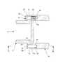
図1及び図2に示すように、本発明に係る軸継手は、回転可能に支持される出力軸(駆動軸)11と入力軸(被駆動軸)21とを連結し、出力軸11の動力(トルク)を入力軸21に伝達するものである。 As shown in FIGS. 1 and 2, the shaft coupling according to the present invention connects an output shaft (drive shaft) 11 and an input shaft (driven shaft) 21 that are rotatably supported, and the power of the
出力軸11は円筒状に形成されており、その端部にはフランジ部12が設けられている。フランジ部12には、貫通孔である複数のボルト孔13及びピン孔14が形成されており、これらボルト孔13とピン孔14とは、フランジ部12の周方向において、交互に等角度間隔で配置されている。なお、フランジ部12は、入力軸21側の合わせ面12aと、この合わせ面12aの反対側の着座面12bとを有している。 The
また、入力軸21は円筒状に形成されており、その端部には、フランジ部12の合わせ面12aと面する合わせ面22が設けられている。合わせ面22には、有底孔である複数のボルト孔23及びピン孔24が形成されており、これらボルト孔23とピン孔24とは、合わせ面22の周方向において、交互に等角度間隔で配置されている。そして、ボルト孔23の内周面には、めねじ部23aが形成されている。なお、ボルト孔13,23及びピン孔14,24は、同じ内径に形成されている。 The
即ち、出力軸11の合わせ面12aと入力軸21の合わせ面22との連結時においては、ボルト孔13,23同士が対接して連通する共に、ピン孔14,24同士が対接して連通することになる。そして、対接したボルト孔13,23には、ボルト31が挿入されると共に、対接したピン孔14,24には、ピン41が挿入されている。 That is, when the
ボルト31は、図示しない六角レンチが係合可能な六角形状の頭部32と、この頭部32の端部に形成されるフランジ部33と、その先端側に形成されるおねじ部34とを有している。従って、ボルト31を対接したボルト孔13,23に挿入することにより、フランジ部33がフランジ部12の着座面12bに着座すると共に、おねじ部34がボルト孔23のめねじ部23aと螺合する。これにより、合わせ面12a,22間に締結力が与えられることになる。なお、このような、ボルト31の締結時においては、そのフランジ部33がナットや座金と同じ役割を果たすため、ボルト31の緩み防止が図られている。 The
また、ピン41は、棒状で、且つ、その長さが対接したピン孔14,24の長さと同じ長さ(深さ)に形成されている。従って、ピン41を対接したピン孔14,24に挿入することにより、出力軸11の駆動(回転)時において、ピン41自体のせん断力によって、出力軸11の動力が入力軸21に伝達されることになる。 The
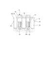
ここで、図1乃至図3に示すように、フランジ部33の半径は、ボルト孔13,23とピン孔14,24との間の軸間距離よりも若干短く形成されている。これにより、ボルト31の締結時においては、そのフランジ部33の一部分が、当該ボルト31が挿入されたボルト孔13,23に隣接する両側のピン孔14,24の開口部の一部分を覆い被さるようになっている。 Here, as shown in FIGS. 1 to 3, the radius of the
即ち、ピン孔14,24に対して、フランジ部12の周方向両側から、フランジ部33が張り出すことになるため、このフランジ部33の張り出し部分に、当該ピン孔14,24に挿入されたピン41の端面が当接することになる。これにより、ボルト31のフランジ部33によって、ピン41の抜け防止が図られている。 That is, since the
また、上述したように、フランジ部33がピン孔14,24に覆い被さるようにしたことにより、動力伝達時の振動によって、ピン41がフランジ部33側に移動した場合には、このピン41がフランジ部33を押圧することになる。これにより、ボルト31に対して、その引き抜き方向に押圧力が作用するため、ボルト31のおねじ部34とボルト孔23のめねじ部23aとの間の螺合力が大きくなり、更にボルト31の緩み防止が図られることになる。 Further, as described above, since the
そして、軸継手を組み立てる場合には、先ず、出力軸11の合わせ面12aと入力軸21の合わせ面22とを対接させ、互いのボルト孔13,23及びピン孔14,24を整合させる。次いで、ピン41を対接したピン孔14,24に挿入した後、ボルト31を対接したボルト孔13,23に挿入して、そのフランジ部33をフランジ部12の着座面12bに当接させると共に、おねじ部34をボルト孔23のめねじ部23aと螺合させる。これにより、出力軸11と入力軸21とは、連結状態となり、フランジ部33の一部分は、ピン孔14,24の開口部の一部分を覆うことになる。 When assembling the shaft coupling, first, the
ここで、ボルト31及びピン41を挿入する場合には、ピン41をピン孔14,24に完全に挿入してから、ボルト31をボルト孔13,23に挿入してもよく、また、ピン41の途中までをピン孔14,24に挿入した状態で、ボルト31を挿入しながら、そのフランジ部12によって、ピン41を押し込んで完全に挿入してもよい。 Here, when the
従って、出力軸11を駆動させることにより、その動力はピン41自体のせん断力によって、入力軸21に伝達される。このとき、ボルト31のフランジ部33によって、当該ボルト31の緩み防止及びピン41の抜け防止が図られている。 Therefore, by driving the
なお、上述した実施形態においては、出力軸11だけにフランジ部12を設けるようにしたが、入力軸21にも同様のフランジ部を設けたり、入力軸21だけにフランジ部を設けたりしても良く、また、出力軸11及び入力軸21の双方に、フランジ部を設けることなく、合わせ面のみを備えるようにしても構わない。 In the above-described embodiment, the
また、フランジ部33を、ボルト31に対して一体的に形成したが、別体としても構わない。即ち、フランジ部33を座金となるように別体に設けても構わない。 Moreover, although the
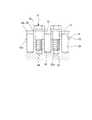
更に、ピン41の長さを、連結時に対接したピン孔14,24の長さと同じ長さになるように形成したが、図4に示すように、対接したピン孔14,24の長さよりも短い長さのピン42を用い、このピン42とフランジ部33との間に、樹脂、ゴム、皿ばね等の弾性部材51を介在させるようにしても構わない。これにより、振動によりピン42がフランジ部33側に移動しなくても、常に弾性部材51がフランジ部33を押圧することになる。この結果、ボルト31に対して、常にその引き抜き方向に押圧力が作用するため、ボルト31の緩み防止を向上させることができる。 Furthermore, although the length of the
従って、本発明に係る軸継手によれば、出力軸11の合わせ面12aと入力軸12の合わせ面22とを貫通するボルト孔13,23及びピン孔14,24に、ボルト31及びピン41を挿入したときに、ボルト31に設けたフランジ部33が、合わせ面12aの反対側の着座面12bに着座して、ピン孔14,24を覆うようにしたことにより、部品点数が削減されて簡素な構成をなすと共に、ボルト31の緩み防止及びピン41の抜け防止を図ることができる。 Therefore, according to the shaft coupling according to the present invention, the
また、ボルト31にフランジ部33を設けることにより、従来の軸継手において用いられていたナット、座金、ねじ止めピン等を必要としないため、ボルト31及びピン41だけを使用することになり、組み立て作業や分解作業を容易に行うことができる。更に、従来の軸継手において用いられていたねじ止めピンは、軸継手分解後において再使用が困難となるが、再使用可能なボルト31及びピン41だけを使用しているので、コスト低減を図ることができる。 Further, by providing the
本発明は、耐久性及び動力伝達の信頼性を向上させる軸継手に適用可能である。 The present invention is applicable to a shaft coupling that improves durability and reliability of power transmission.
11 出力軸
12 フランジ部
12a 合わせ面
12b 座面
13 ボルト孔
14 ピン孔
21 入力軸
22 合わせ面
23 ボルト孔
23a めねじ部
24 ピン孔
31 ボルト
32 頭部
33 フランジ部
34 おねじ部
41,42 ピン
51 弾性部材11
Claims (4)
Translated fromJapanese前記第1合わせ面と前記第2合わせ面とを貫通するボルト孔及びピン孔と、
前記ボルト孔に挿入され、前記第1合わせ面と前記第2合わせ面との間に締結力を与えるボルトと、
前記ピン孔に挿入され、それ自体のせん断力によって、前記第1合わせ面と前記第2合わせ面との間で動力を伝達するピンとを備え、
前記ボルトは、
前記第1合わせ面または前記第2合わせ面の反対側の着座面に着座し、且つ、前記ピン孔を覆うフランジ部を有する
ことを特徴とする軸継手。The first mating surface provided at the end of the first rotating shaft and the second mating surface provided at the end of the second rotating shaft so that the first rotating shaft and the second rotating shaft are uniaxial. In the shaft coupling that connects
A bolt hole and a pin hole penetrating the first mating surface and the second mating surface;
A bolt that is inserted into the bolt hole and provides a fastening force between the first mating surface and the second mating surface;
A pin that is inserted into the pin hole and transmits power between the first mating surface and the second mating surface by its own shearing force;
The bolt is
A shaft coupling comprising a flange portion that is seated on a seating surface opposite to the first mating surface or the second mating surface and covers the pin hole.
前記ボルト孔と前記ピン孔とを周方向に交互に設け、
前記ピンが挿入された前記ピン孔は、当該ピン孔に隣接した前記ボルト孔に挿入された前記ボルトの前記フランジ部に覆われる
ことを特徴とする軸継手。The shaft coupling according to claim 1,
The bolt holes and the pin holes are alternately provided in the circumferential direction,
The pin hole into which the pin is inserted is covered with the flange portion of the bolt inserted into the bolt hole adjacent to the pin hole.
前記ピンと前記フランジ部とは当接する
ことを特徴とする軸継手。The shaft coupling according to claim 1 or 2,
The shaft and the flange are in contact with each other.
前記フランジ部と前記ピンとの間に弾性部材を設ける
ことを特徴とする軸継手。The shaft coupling according to claim 1 or 2,
An axial member is provided between the flange portion and the pin.
Priority Applications (1)
| Application Number | Priority Date | Filing Date | Title |
|---|---|---|---|
| JP2009041853AJP5055313B2 (en) | 2009-02-25 | 2009-02-25 | Shaft coupling |
Applications Claiming Priority (1)
| Application Number | Priority Date | Filing Date | Title |
|---|---|---|---|
| JP2009041853AJP5055313B2 (en) | 2009-02-25 | 2009-02-25 | Shaft coupling |
Publications (2)
| Publication Number | Publication Date |
|---|---|
| JP2010196771A JP2010196771A (en) | 2010-09-09 |
| JP5055313B2true JP5055313B2 (en) | 2012-10-24 |
Family
ID=42821695
Family Applications (1)
| Application Number | Title | Priority Date | Filing Date |
|---|---|---|---|
| JP2009041853AExpired - Fee RelatedJP5055313B2 (en) | 2009-02-25 | 2009-02-25 | Shaft coupling |
Country Status (1)
| Country | Link |
|---|---|
| JP (1) | JP5055313B2 (en) |
Families Citing this family (1)
| Publication number | Priority date | Publication date | Assignee | Title |
|---|---|---|---|---|
| US8578799B2 (en) | 2010-11-24 | 2013-11-12 | Arthur N. Maupin | Method and system for shaft coupling |
Family Cites Families (4)
| Publication number | Priority date | Publication date | Assignee | Title |
|---|---|---|---|---|
| JPS578929U (en)* | 1980-06-16 | 1982-01-18 | ||
| JPS62185916U (en)* | 1986-05-19 | 1987-11-26 | ||
| JPS6451702U (en)* | 1987-09-29 | 1989-03-30 | ||
| JP2008298174A (en)* | 2007-05-31 | 2008-12-11 | Jfe Steel Kk | Mechanical fuse and connecting structure of power transmission system provided with the mechanical fuse |
- 2009
- 2009-02-25JPJP2009041853Apatent/JP5055313B2/ennot_activeExpired - Fee Related
Also Published As
| Publication number | Publication date |
|---|---|
| JP2010196771A (en) | 2010-09-09 |
Similar Documents
| Publication | Publication Date | Title |
|---|---|---|
| US9322426B2 (en) | Nut and sleeve fastener | |
| CN104675820B (en) | Grooves and keys for asymmetrical fasteners | |
| US7213999B2 (en) | Fastener with opposite hand threads for securing two components together | |
| US7524132B2 (en) | Pinch bolt-split hub attachment assembly | |
| JP5360848B1 (en) | Nut locking device | |
| JP2001140835A (en) | Bolt and fastening device with this bolt | |
| CN108370105B (en) | Electrical connectors and connection methods | |
| JP5814021B2 (en) | Connector with bolt | |
| CN210106370U (en) | Fastening system, to-be-assembled part and self-locking nut with reverse teeth | |
| JP5055313B2 (en) | Shaft coupling | |
| JP2009275528A (en) | Shaft coupling and pump device having the same | |
| KR101338447B1 (en) | Connecting structure of wheel bearing | |
| KR20040063758A (en) | A nut, a fastener provided with a nut, and a fastening device therefor | |
| US20150117942A1 (en) | Dowel element | |
| KR20160002425U (en) | Apparatus for preventing misassembling of a universal joint | |
| KR200387751Y1 (en) | Anti-loose Nut | |
| JP2004293565A (en) | Bolt fastening structure | |
| CN221170442U (en) | A fastening structure and automobile power transmission system | |
| KR101322428B1 (en) | Connecting structure of wheel bearing | |
| JP4356937B2 (en) | Oldham fitting | |
| JP3755985B2 (en) | Shaft fastener | |
| KR20130034711A (en) | Apparatus for preventing misassembling of a universal joint | |
| JP2011226587A (en) | Sliding constant velocity universal joint | |
| JP2010209562A (en) | Tight structure | |
| KR101515895B1 (en) | Connecting tool for stud bolt |
Legal Events
| Date | Code | Title | Description |
|---|---|---|---|
| A621 | Written request for application examination | Free format text:JAPANESE INTERMEDIATE CODE: A621 Effective date:20111021 | |
| TRDD | Decision of grant or rejection written | ||
| A01 | Written decision to grant a patent or to grant a registration (utility model) | Free format text:JAPANESE INTERMEDIATE CODE: A01 Effective date:20120710 | |
| A01 | Written decision to grant a patent or to grant a registration (utility model) | Free format text:JAPANESE INTERMEDIATE CODE: A01 | |
| A977 | Report on retrieval | Free format text:JAPANESE INTERMEDIATE CODE: A971007 Effective date:20120712 | |
| A61 | First payment of annual fees (during grant procedure) | Free format text:JAPANESE INTERMEDIATE CODE: A61 Effective date:20120730 | |
| FPAY | Renewal fee payment (event date is renewal date of database) | Free format text:PAYMENT UNTIL: 20150803 Year of fee payment:3 | |
| LAPS | Cancellation because of no payment of annual fees |