JP5054989B2 - Liquid infusion tool - Google Patents
Liquid infusion toolDownload PDFInfo
- Publication number
- JP5054989B2 JP5054989B2JP2007015249AJP2007015249AJP5054989B2JP 5054989 B2JP5054989 B2JP 5054989B2JP 2007015249 AJP2007015249 AJP 2007015249AJP 2007015249 AJP2007015249 AJP 2007015249AJP 5054989 B2JP5054989 B2JP 5054989B2
- Authority
- JP
- Japan
- Prior art keywords
- branch pipe
- rubber plug
- liquid
- chamber
- upper branch
- Prior art date
- Legal status (The legal status is an assumption and is not a legal conclusion. Google has not performed a legal analysis and makes no representation as to the accuracy of the status listed.)
- Active
Links
Images


Classifications
- A—HUMAN NECESSITIES
- A61—MEDICAL OR VETERINARY SCIENCE; HYGIENE
- A61M—DEVICES FOR INTRODUCING MEDIA INTO, OR ONTO, THE BODY; DEVICES FOR TRANSDUCING BODY MEDIA OR FOR TAKING MEDIA FROM THE BODY; DEVICES FOR PRODUCING OR ENDING SLEEP OR STUPOR
- A61M39/00—Tubes, tube connectors, tube couplings, valves, access sites or the like, specially adapted for medical use
- A61M39/02—Access sites
- A61M39/04—Access sites having pierceable self-sealing members
- A61M39/045—Access sites having pierceable self-sealing members pre-slit to be pierced by blunt instrument
- A—HUMAN NECESSITIES
- A61—MEDICAL OR VETERINARY SCIENCE; HYGIENE
- A61M—DEVICES FOR INTRODUCING MEDIA INTO, OR ONTO, THE BODY; DEVICES FOR TRANSDUCING BODY MEDIA OR FOR TAKING MEDIA FROM THE BODY; DEVICES FOR PRODUCING OR ENDING SLEEP OR STUPOR
- A61M39/00—Tubes, tube connectors, tube couplings, valves, access sites or the like, specially adapted for medical use
- A61M39/22—Valves or arrangement of valves
- A61M39/223—Multiway valves
- A—HUMAN NECESSITIES
- A61—MEDICAL OR VETERINARY SCIENCE; HYGIENE
- A61M—DEVICES FOR INTRODUCING MEDIA INTO, OR ONTO, THE BODY; DEVICES FOR TRANSDUCING BODY MEDIA OR FOR TAKING MEDIA FROM THE BODY; DEVICES FOR PRODUCING OR ENDING SLEEP OR STUPOR
- A61M39/00—Tubes, tube connectors, tube couplings, valves, access sites or the like, specially adapted for medical use
- A61M2039/0036—Tubes, tube connectors, tube couplings, valves, access sites or the like, specially adapted for medical use characterised by a septum having particular features, e.g. having venting channels or being made from antimicrobial or self-lubricating elastomer
- A—HUMAN NECESSITIES
- A61—MEDICAL OR VETERINARY SCIENCE; HYGIENE
- A61M—DEVICES FOR INTRODUCING MEDIA INTO, OR ONTO, THE BODY; DEVICES FOR TRANSDUCING BODY MEDIA OR FOR TAKING MEDIA FROM THE BODY; DEVICES FOR PRODUCING OR ENDING SLEEP OR STUPOR
- A61M39/00—Tubes, tube connectors, tube couplings, valves, access sites or the like, specially adapted for medical use
- A61M39/22—Valves or arrangement of valves
- A61M39/26—Valves closing automatically on disconnecting the line and opening on reconnection thereof
Landscapes
- Health & Medical Sciences (AREA)
- Heart & Thoracic Surgery (AREA)
- Pulmonology (AREA)
- Engineering & Computer Science (AREA)
- Anesthesiology (AREA)
- Biomedical Technology (AREA)
- Hematology (AREA)
- Life Sciences & Earth Sciences (AREA)
- Animal Behavior & Ethology (AREA)
- General Health & Medical Sciences (AREA)
- Public Health (AREA)
- Veterinary Medicine (AREA)
- Infusion, Injection, And Reservoir Apparatuses (AREA)
- Branch Pipes, Bends, And The Like (AREA)
- Casting Or Compression Moulding Of Plastics Or The Like (AREA)
- Processing And Handling Of Plastics And Other Materials For Molding In General (AREA)
Description
Translated fromJapanese本発明は、医療に用いられる複数の輸液チューブ等に連結されて、各輸液チューブ間に薬液等を流す液体混注具に関する。 The present invention relates to a liquid co-infusion device that is connected to a plurality of infusion tubes or the like used for medical treatment and allows a medical solution or the like to flow between the infusion tubes.
従来から、複数の輸液チューブを用いて患者の体内に所定の薬液や生理食塩水等を供給することが行われており、このような場合に、医療用活栓等の液体混注具を用いて、各輸液チューブ間を連通したり遮断したりすることが行われている。このような、液体混注具の中に、複数の分岐管を備え、それらの分岐管のうちの所定の分岐管内に、注射針等を穿刺可能なゴム栓が取り付けられたものがある(例えば、特許文献1参照)。
この液体混注具は、本体部分から水平方向に延びる2個の分岐管と、本体部分の上部に形成された注射器接続ポートとを備えている。そして、この注射器接続ポートに、上下に貫通する挿通部が形成されたシール弁体が設けられている。このため、シール弁体の挿通部にツイストロック式注射器を挿し込むことにより、ツイストロック式注射器と液体混注具の本体内とを連通させることができる。これによって、ツイストロック式注射器から液体混注具の本体内に薬液を注入したり、液体混注具の本体から薬液を抽出したりすることができる。 This liquid co-infusion device includes two branch pipes extending in the horizontal direction from the main body portion, and a syringe connection port formed at the upper portion of the main body portion. The syringe connection port is provided with a seal valve body in which an insertion portion penetrating vertically is formed. For this reason, the twist lock type syringe and the inside of the main body of the liquid co-infusion device can be communicated by inserting the twist lock type syringe into the insertion portion of the seal valve body. Thereby, a chemical | medical solution can be inject | poured in the main body of a liquid co-infusion device from a twist lock type syringe, or a chemical | medical solution can be extracted from the main body of a liquid co-infusion device.
しかしながら前述した従来の液体混注具では、シール弁体の挿通部にツイストロック式注射器を挿し込むときに、シール弁体の下部が液体混注具内の空間部に押し出されて突出する。このため、シール弁体における液体混注具内の空間部に突出した部分の周囲に空気が滞留し易くなる。この結果、液体混注具内や輸液ラインのチューブ内に滞留する空気を除去するための操作が必要になり、かつこの操作が面倒になるという問題が生じている。また、空気が滞留することにより、液体混注具内に菌が発生し易くなるという問題もある。 However, in the conventional liquid co-infusion device described above, when the twist-lock type syringe is inserted into the insertion portion of the seal valve body, the lower portion of the seal valve body is pushed out into the space portion in the liquid co-infusion device and protrudes. For this reason, it becomes easy for air to stay around the part which protruded in the space part in the liquid co-infusion tool in a seal valve body. As a result, there is a problem that an operation for removing the air staying in the liquid co-infusion device or the tube of the infusion line is required, and this operation becomes troublesome. Moreover, there is also a problem that bacteria are easily generated in the liquid co-infusion device due to the retention of air.
本発明は、このような事情に鑑みなされたもので、その目的は、内部に空気が滞留し難くなる液体混注具を提供することにある。 The present invention has been made in view of such circumstances, and an object of the present invention is to provide a liquid co-infusion device in which air hardly stays inside.
前述した目的を達成するため、本発明に係る液体混注具の構成上の特徴は、チャンバー部と、チャンバー部から上方に延びる上部分岐管と、チャンバー部から略水平方向の上流側に延びる上流分岐管と、チャンバー部から略水平方向の下流側に延びる下流分岐管とからなる混注具本体と、上部分岐管に取り付けられ、内部を貫通するスリットを閉じることにより上部分岐管を閉塞するとともに、スリットに接続管を挿通させることによりチャンバー部内と接続管内とを連通させるゴム栓とを備えた液体混注具であって、ゴム栓を、上部分岐管に固定された固定片と、固定片に連結され、接続管をスリットに挿入することにより、接続管の外周面に沿って上部分岐管の内部下部側に押し込まれるゴム栓本体とで構成し、上流分岐管からチャンバー部を介して下流分岐管に液体を流す際に、その液体を上部分岐管の下部側部分を通過させるための堰部を、上部分岐管の内周面下部側に掛け渡して設けるとともに、堰部の上端部両側部分にゴム栓受け部を形成し、ゴム栓本体が上部分岐管の内部下部側に押し込まれたときにゴム栓本体の下端部がゴム栓受け部に当接して、ゴム栓本体と接続管との間およびゴム栓本体とゴム栓受け部との間に空気が滞留する隙間を生じさせないように変形することにある。To achieve the above object, features in configuration of the fluid mixture delivery instrument pertaining to the present inventionextends a chamber portion,an upper branchpipe extending to the chamber part oral upperside, on the upstream side of the substantially horizontal direction from the chamber portion A co-injector body consisting of anupstream branch pipe and a downstream branch pipe extending from the chamber portion to the downstream side in a substantially horizontal direction, and an upper branch pipe attached to the upper branch pipe and closing the slit penetrating the inside are closed. , A liquid co-infusion device comprising a rubber plug that allows the inside of the chamber and the connecting pipe to communicate with each other by inserting the connecting pipe through the slit, the rubber plug being fixed to the upper branch pipe, and the fixed piece are connected by inserting the connecting pipe into the slit, and composed of a rubber stopper body to be pushed into the lower side of the upper branch pipe along the outer circumferential surface of the connectingpipe, the chamber from the upstream branch tube And a weir for passing the liquid through the lower branch portion of the upper branch pipe when the liquid flows to the downstream branch pipe through the section. the upper end side portions of the part to form a rubber plug receiving portion, the lower endportion ofKinigo arm stopper body and the rubber stopper main body is pushed inside the bottom side of the upper branch pipeis in contact with the rubber plug receiving portion, a rubber The object is to deform so as not to cause a gap in which air stays between the plug body and the connecting pipe and between the rubber plug body and the rubber plug receiving portion .
前述したように構成した本発明の液体混注具では、接続管、例えばシリンジの雄ルアー部をゴム栓本体のスリットに挿通させて接続管をチャンバー部に連通させる際に、ゴム栓本体が接続管により上部分岐管の内部下部側に押し込まれると、ゴム栓本体における上部分岐管の内部下部側に位置する下端部は、上部分岐管の内部下部側に設けられたゴム栓受け部に押し付けられて密着する。そして、ゴム栓本体の下端部がゴム栓受け部に密着することによって、接続管とチャンバー部とを連通する流路内に空気が滞留するような隙間がほとんど生じないようにしている。 In the liquid co-infusion device of the present invention configured as described above, when the connecting tube, for example, the male luer part of the syringe is inserted into the slit of the rubber plug body and the connecting tube is communicated with the chamber part, the rubber plug body is connected to the connecting tube. When pushed into the lower part inside the upper branch pipe, the lower end portion located on the lower inner side of the upper branch pipe in the rubber plug body is pressed against the rubber stopper receiving part provided on the lower inner side of the upper branch pipe. In close contact. And since the lower end part of a rubber plug main body closely_contact | adheres to a rubber plug receiving part, the clearance gap which air retains in the flow path which connects a connecting pipe and a chamber part is hardly produced.
すなわち、接続管とチャンバー部とを連通する流路内に液体が流れる空間以外の隙間がほとんど生じなくなるため、接続管からチャンバー部内に薬液等の液体を流す場合には、接続管とチャンバー部とを連通する流路内の空間部のほとんどすべての部分に薬液等が通るようになる。この結果、チャンバー部内の空気を除去するために面倒な操作をする必要がなくなるとともに、チャンバー部内に菌が発生することを抑制できる。また、薬液等の供給が終わり接続管をゴム栓本体から抜いたときには、ゴム栓本体は固定片やそれ自身の復元力によって元の位置に戻り、スリットは閉塞される。 That is, there is almost no gap other than the space in which the liquid flows in the flow path that connects the connecting tube and the chamber portion. Therefore, when a liquid such as a chemical solution flows from the connecting tube into the chamber portion, the connecting tube and the chamber portion The chemical solution or the like passes through almost all of the space in the flow path that communicates with each other. As a result, it is not necessary to perform a troublesome operation to remove the air in the chamber portion, and it is possible to suppress the generation of bacteria in the chamber portion. Further, when the supply of the chemical solution or the like is finished and the connecting pipe is removed from the rubber plug body, the rubber plug body returns to the original position by the restoring force of the fixing piece or itself, and the slit is closed.
なお、この場合、接続管とチャンバー部とを連通する流路内に空気が滞留する隙間が生じることを防止するためには、例えば、ゴム栓受け部の形状をゴム栓本体の下端部が押し付けられる底部と側部を備えた形状にする。そして、接続管の外周面に沿って下方に延びるゴム栓本体の下端部をゴム栓受け部に押し付けたときに、ゴム栓本体と接続管との間およびゴム栓本体とゴム栓受け部との間にそれぞれ段差等の隙間ができないようにする。これによって、液体が流れる空間部以外の隙間がほとんど生じない流路を形成することができる。すなわち、接続管とチャンバー部とを連通する流路内に空気が滞留する隙間が生じる場合としては、接続管の先端部がゴム栓本体の下面から突出してその突出部分の周囲に隙間が生じ易くなっていたり、ゴム栓本体の下端部に凹凸が生じていたりしたとき等が考えられる。 In this case, for example, in order to prevent a gap in which air stays in the flow path connecting the connecting pipe and the chamber portion, the shape of the rubber plug receiving portion is pressed by the lower end portion of the rubber plug body. The shape is provided with a bottom and side portions. When the lower end portion of the rubber plug body extending downward along the outer peripheral surface of the connecting pipe is pressed against the rubber plug receiving section, between the rubber plug main body and the connecting pipe and between the rubber plug main body and the rubber plug receiving section. Make sure there are no gaps between them. As a result, it is possible to form a flow path in which there is almost no gap other than the space where the liquid flows. That is, when a gap in which air stays in the flow path that connects the connecting pipe and the chamber portion is generated, the tip of the connecting pipe protrudes from the lower surface of the rubber plug body, and a gap is easily generated around the protruding portion. It can be considered that the rubber plug body is uneven or the bottom end of the rubber plug body is uneven.
このため、接続管とチャンバー部とを連通させたときや、ゴム栓が閉塞しているときに、このようなことが生じることを防止することにより接続管とチャンバー部とを連通する流路内に空気が滞留することを防止できる。また、複数の分岐管は、それぞれチャンバー部から延びる液体流路を備えた管であり、上部分岐管と、その他の1個又は複数個の管で構成される。さらに、本発明に係る液体混注具としては、所定の分岐管を連通させたり遮断したりする弁体を備えた活栓タイプのものや、弁体を備えず、常時連通した分岐管間で薬液等を流せるタイプのものを用いることができる。 For this reason, when the connecting pipe communicates with the chamber part, or when the rubber plug is closed, the occurrence of such a situation prevents the connecting pipe from connecting to the chamber part. It is possible to prevent air from being retained. The plurality of branch pipes are pipes each having a liquid flow path extending from the chamber portion, and are configured by an upper branch pipe and one or more other pipes. Furthermore, as the liquid co-infusion device according to the present invention, a stopcock type provided with a valve body that allows a predetermined branch pipe to communicate with or shut off, a chemical solution, etc. between branch pipes that do not have a valve body and are always in communication Can be used.
また、本発明に係る液体混注具では、複数の分岐管を、上部分岐管と、チャンバー部から略水平方向の上流側に延びる上流分岐管と、チャンバー部から略水平方向の下流側に延びる下流分岐管とで構成して、上流分岐管からチャンバー部を介して下流分岐管に液体を流す際に、その液体を上部分岐管の下部側部分を通過させるための堰部を設け、堰部の上端部両側部分にゴム栓受け部を形成している。Further, in the liquid co-infusiondevice according to the present invention, the plurality of branch pipes include an upper branch pipe, an upstream branch pipe extending from the chamber portion to the upstream side in the substantially horizontal direction, and a downstream extending from the chamber portion to the downstream side in the substantially horizontal direction. When the liquid flows from the upstream branch pipe to the downstream branch pipe through the chamber section, a weir section is provided for passing the liquid through the lower side portion of the upper branch pipe.forming arubber Sen受 only parts on the upper end side portions.
これによると、液体が上流分岐管からチャンバー部を介して下流分岐管に流れる際に、堰部を乗り越えて上部分岐管の下部側部分(チャンバー部の上部側部分)を通過するため、その液体は、上部分岐管の下部側に形成される空間部全体に流れるようになる。この結果、上部分岐管の下部側部分に空気が滞留することがさらに効果的に防止される。すなわち、チャンバー部内を液体が流れる場合には、チャンバー部内の空間部から上流分岐管の下部側部分のすべての部分に液体が通るようになる。このため、チャンバー部や上流分岐管の内部に空気が滞留することが抑制される。 According to this, when the liquid flows from the upstream branch pipe to the downstream branch pipe through the chamber section, it passes over the weir section and passes through the lower part of the upper branch pipe (the upper part of the chamber part). Flows through the entire space formed on the lower side of the upper branch pipe. As a result, it is possible to more effectively prevent air from staying in the lower part of the upper branch pipe. That is, when the liquid flows in the chamber portion, the liquid passes from the space portion in the chamber portion to all the portions on the lower side portion of the upstream branch pipe. For this reason, it is suppressed that air retains inside a chamber part or an upstream branch pipe.
また、本発明に係る液体混注具のさらに他の構成上の特徴は、ゴム栓のスリットに接続管が挿入されてないときのゴム栓本体の下面の形状を略ドーム状にして、スリットを閉じて上部分岐管を閉塞した状態で、上流分岐管からチャンバー部を介して下流分岐管に液体を流して液体が上部分岐管の下部側部分を通過する際に、ゴム栓本体の下面に空気が滞留することを防止できるようにしたことにある。これによると、ゴム栓のスリットが閉じて上部分岐管がチャンバー部に対して閉塞された状態のときに、上流分岐管からチャンバー部を介して下流分岐管に流れる液体の流路を確保できるとともに、ゴム栓本体の下面に空気が滞留することを防止できる。 Further, another structural feature of the liquid co-infusion device according to the present invention is that the shape of the bottom surface of the rubber plug main body when the connecting pipe is not inserted into the slit of the rubber plug is substantially domed, and the slit is closed. With the upper branch pipe closed, air flows from the upstream branch pipe through the chamber to the downstream branch pipe, and when the liquid passes through the lower part of the upper branch pipe, This is to prevent the stagnation. According to this, when the slit of the rubber plug is closed and the upper branch pipe is closed with respect to the chamber part, it is possible to secure a flow path for the liquid flowing from the upstream branch pipe to the downstream branch pipe through the chamber part. It is possible to prevent air from staying on the lower surface of the rubber plug body.
また、本発明に係る液体混注具のさらに他の構成上の特徴は、接続管によってゴム栓本体が上部分岐管の内部下部側に押し込まれたときのゴム栓本体の下端部の形状が、接続管の先端部からゴム栓受け部に向って下方に広がったテーパ状の面になるようにしたことにある。これによると、接続管の先端部とゴム栓受け部との間に空気が滞留することを効果的に防止できる。この場合のテーパ状の面としては、曲面や平面または複数の曲面や平面を繋いで形成される面等を用いることができる。 Further, another structural feature of the liquid co-infusion device according to the present invention is that the shape of the lower end portion of the rubber plug body when the rubber plug body is pushed into the inner lower side of the upper branch pipe by the connection pipe is The taper-shaped surface that spreads downward from the tip of the tube toward the rubber plug receiving portion is provided. According to this, it can prevent effectively that air retains between the front-end | tip part of a connection pipe, and a rubber stopper receiving part. As the tapered surface in this case, a curved surface, a flat surface, a surface formed by connecting a plurality of curved surfaces or flat surfaces, or the like can be used.
また、本発明に係る液体混注具のさらに他の構成上の特徴は、上部分岐管を、チャンバー部側部分の直径が上端開口部側の直径よりも大きくなった略円筒状に形成し、ゴム栓本体が上部分岐管の内部下部側に押し込まれるときに、水平方向に広がるように変形しながら下降するようにしたことにある。 Still another structural feature of the liquid co-infusion device according to the present invention is that the upper branch pipe is formed in a substantially cylindrical shape in which the diameter of the chamber portion side portion is larger than the diameter of the upper end opening portion side, and rubber When the stopper main body is pushed into the lower part inside the upper branch pipe, it is lowered while deforming so as to spread in the horizontal direction.
これによると、接続管をゴム栓のスリットに挿入してゴム栓本体を上部分岐管の内部側に押し込むときのゴム栓の変形量(下方への伸び)を小さくすることができる。このため、固定片や固定片とゴム栓本体との連結部近傍部分の延びも少なくて済み、その部分に無理な力がかからなくなる。これによって、ゴム栓が破損し難くなる。また、ゴム栓本体を上部分岐管の内部下部側に押し込んだときにゴム栓受け部に当接するゴム栓本体の下部の形状をより適切な形状に変形させ易くなる。 According to this, the deformation amount (downward extension) of the rubber plug when the connecting pipe is inserted into the slit of the rubber plug and the rubber plug main body is pushed into the inner side of the upper branch pipe can be reduced. For this reason, there is little extension of the fixing piece or the vicinity of the connecting portion between the fixing piece and the rubber plug main body, and no excessive force is applied to that portion. This makes it difficult for the rubber stopper to break. In addition, when the rubber plug main body is pushed into the lower part inside the upper branch pipe, the shape of the lower portion of the rubber plug main body that comes into contact with the rubber plug receiving portion can be easily changed to a more appropriate shape.
また、本発明に係る液体混注具のさらに他の構成上の特徴は、上部分岐管を、チャンバー部と一体に形成された連結用開口部と、連結用開口部に取り付けられた略円筒状部材とで構成し、ゴム栓の固定片を、略円筒状部材の上端開口部側に固定された上部固定片と、連結用開口部と略円筒状部材との間に固定された下部固定片とで構成したことにある。 Still another structural feature of the liquid co-infusion device according to the present invention is that the upper branch pipe is formed with a connecting opening integrally formed with the chamber portion, and a substantially cylindrical member attached to the connecting opening. And a rubber stopper fixing piece, an upper fixing piece fixed to the upper opening side of the substantially cylindrical member, and a lower fixing piece fixed between the connection opening and the substantially cylindrical member, It is in the configuration.
これによると、上部分岐管へのゴム栓の取り付けが容易になる。また、ゴム栓の上部固定片を上部分岐管の上端開口部側に固定し、ゴム栓の下部固定片を連結用開口部と略円筒状部材との間に固定したため、ゴム栓本体が接続管によって上部分岐管の内部下部側に押し込まれるときには、上部固定片側が大きく伸長し下部固定片側が変形するかやや伸長する。このため、接続管をゴム栓本体から抜いたときには、ゴム栓本体は上部固定片と下部固定片との双方の復元力によって、上部分岐管の上端開口部側の位置に戻り、スリットはゴム栓本体の復元力によって閉塞される。この結果、上部分岐管の開口部を確実に閉塞することができる。この場合、ゴム栓本体は上部固定片と下部固定片とによって支持されるため、強固な取り付けが可能になる。 According to this, it is easy to attach the rubber stopper to the upper branch pipe. Also, since the upper fixed piece of the rubber plug is fixed to the upper opening side of the upper branch pipe and the lower fixed piece of the rubber plug is fixed between the connecting opening and the substantially cylindrical member, the rubber plug main body is connected to the connecting pipe. When being pushed into the lower part inside the upper branch pipe, the upper fixed piece side is greatly extended and the lower fixed piece side is deformed or slightly extended. For this reason, when the connecting pipe is removed from the rubber plug body, the rubber plug body returns to the position on the upper opening side of the upper branch pipe by the restoring force of both the upper fixing piece and the lower fixing piece, and the slit is the rubber plug. It is blocked by the restoring force of the main body. As a result, the opening of the upper branch pipe can be reliably closed. In this case, since the rubber plug main body is supported by the upper fixing piece and the lower fixing piece, it can be firmly attached.
また、本発明に係る液体混注具のさらに他の構成上の特徴は、チャンバー部内で移動することにより複数の分岐管のうちの任意の分岐管を連通させる弁体をチャンバー部内に設置したことにある。これによると、液体混注具に連結される各輸液チューブ間の連通・遮断の状態を任意に切り換えることができる。また、この弁体の移動とは、軸周り方向への回転や軸方向への移動である。 Further, another structural feature of the liquid co-infusion device according to the present invention is that a valve body that communicates with any branch pipe among a plurality of branch pipes by moving in the chamber section is installed in the chamber section. is there. According to this, the state of communication / blocking between the infusion tubes connected to the liquid co-infusion device can be arbitrarily switched. Further, the movement of the valve body is rotation in the direction around the axis or movement in the axial direction.
(第1実施形態)
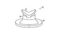
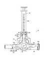
以下、本発明の第1実施形態に係る液体混注具を図面を用いて詳しく説明する。図1ないし図3は、同実施形態に係る液体混注具Aを示しており、この液体混注具Aは、混注具本体10、本発明の略円筒状部材としての蓋部材20、蓋部材20内に取り付けられたゴム栓25(図4および図5参照)および混注具本体10内に取り付けられた弁体30で構成されている。そして、混注具本体10は、軸方向の長さが短い円筒状のチャンバー部11と、チャンバー部11の外周面に90度の角度を保って順に連結された下流分岐管12、連結用開口部13および上流分岐管14からなる3個の分岐管とで構成されている。なお、連結用開口部13と蓋部材20とで本発明の上部分岐管が構成される。(First embodiment)
Hereinafter, a liquid co-infusion device according to a first embodiment of the present invention will be described in detail with reference to the drawings. 1 to 3 show a liquid co-infusion device A according to the embodiment. The liquid co-infusion device A includes a
チャンバー部11は、軸方向を前後方向(図3および図5では左右方向)に向けて配置され、後部が閉塞された略円筒状に形成されている。そして、チャンバー部11の後壁部11aの内面に、断面形状が略コ字状の係合部15が固定されている。この係合部15は、チャンバー部11の後壁部11aの内面中央に沿った円板部15aと、チャンバー部11の内周面との間に所定の隙間を設けた状態で円板部15aの外周縁部から前方に延びる軸方向の長さが短いリング部15bとで構成されている。そして、リング部15bの外周面における左右両側には、一対の係止用突起15cが形成されている。 The
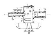
また、チャンバー部11の周壁部における下流分岐管12、連結用開口部13および上流分岐管14が連結された部分には、連通穴16a,16b,16c(図4ないし図6参照)がそれぞれ形成されている。これらの連通穴16a,16b,16cのうち連通穴16bは、中心部の位置を他の連通穴16a,16cの中心部の位置よりもやや前部側にずらして形成されている。そして、連通穴16aを介してチャンバー部11の内部と下流分岐管12の内部に形成された流路12aとが連通し、連通穴16bを介してチャンバー部11の内部と連結用開口部13の内部に形成された流路13aとが連通している。また、連通穴16cを介してチャンバー部11の内部と上流分岐管14の内部に形成された流路14aとが連通している。 Further,
下流分岐管12は、チャンバー部11と一体的に形成されており、チャンバー部11側の基端部12bと、基端部12bよりも細く形成された先端側の雄ルアー部12cとで構成されている。また、雄ルアー部12cは基端部12b側部分よりも先端側部分の方が細くなった先細り状に形成されている。そして、下流分岐管12の外周面における基端部12bと雄ルアー部12cとの境界部には、突部12dが円周に沿って形成されている。 The
上部分岐管の下部側部分を構成する連結用開口部13は、下流分岐管12および上流分岐管14よりも直径が大きく軸方向の長さが短い略リング状に形成されており、上端周縁部における幅方向の略中央に円周に沿って係合溝13bが形成され、外周面における左右両側部分に一対の係合突起13cがそれぞれ形成されている。そして、連結用開口部13の内周面の左右両側には流路13aを前後に仕切る堰部17が掛け渡された状態で形成され、連結用開口部13の上端周縁部における係合溝13bの内側部分から堰部17の上端面にかけての部分に一対のゴム栓受け部18が形成されている。 The connecting
この一対のゴム栓受け部18は、係合溝13bの内周面側の壁部を構成し堰部17の上面17aよりも上方に突出する平面視が円弧状で左右対称に形成された一対の側壁部18aと、堰部17の上面17aの左右両側部分とで構成されている。また、連結用開口部13の係合突起13cには、連結用開口部13とでゴム栓25を固定するための蓋部材20が取り付けられている。蓋部材20は、上部21が下流分岐管12および上流分岐管14よりも直径がやや大きく設定された長さの短い略円筒状に形成され、下部22が連結用開口部13よりもさらに直径が大きく平面視が前後方向に長い楕円形になった軸方向の長さが短い略キャップ状に形成された二段状の略円筒体で構成されている。 The pair of rubber
そして、下部22の左右両側部分の下端部は、前後両側部分の下端部よりも下方に延びており、その下方に延びた部分の内面に、連結用開口部13の係合突起13cと係合可能な一対の係合凹部22aが形成されている。また、上部21の上端開口縁部は、図2に示したように前方から見た状態では、中央側が下方に窪んだ円弧状に形成され、図3に示したように側方から見た状態では、中央側が上方に突出した円弧状に形成されている。そして、上部21の外周面には、ねじ21aが形成されている。この蓋部材20は、下部22の係合凹部22aを係合突起13cに係合させることにより、連結用開口部13に着脱可能に取り付けられている。また、この蓋部材20と連結用開口部13との係合によって、ゴム栓25が固定されている。 The lower end portions of the left and right side portions of the
ゴム栓25は、天然ゴム、合成ゴムまたはエラストマーなどの弾性部材からなっており、図6に示したように、上部側が肉厚円板状に形成され下部側が略ドーム状に形成されたゴム栓本体26と、ゴム栓本体26の上端に形成された上部固定片27と、ゴム栓本体26の下端周縁部の周囲に形成されたリング状の下部固定片28とで構成されている。上部固定片27は、蓋部材20の上端開口縁部に沿う形状に形成されており、ゴム栓本体26の上面における左右の中央からそれぞれ左右の斜め上方に反って湾曲した曲面状の略円板状の部分からなっている。 The
また、図5に示したように、ゴム栓本体26と上部固定片27との境界部分は、ゴム栓本体26における上部側の肉厚円板状の部分と下部側の略ドーム状の部分との境界部よりも大径に形成されている。そして、このように構成されたゴム栓25は、ゴム栓本体26と上部固定片27との境界部分で上部21から外れることを防止された状態で蓋部材20の内部に取り付けられている。また、図4および図5に示したように、下部固定片28を連結用開口部13の係合溝13b内に挿し込んだ状態で蓋部材20の係合凹部22aを連結用開口部13の係合突起13cに係合させることにより、ゴム栓25の下部固定片28は連結用開口部13と蓋部材20とによって固定されている。 Further, as shown in FIG. 5, the boundary between the
すなわち、ゴム栓25は、ゴム栓本体26と上部固定片27との境界の大径部分によって、蓋部材20の内部側に入り込むことを防止され、係合溝13b内に挿し込まれた下部固定片28が連結用開口部13と蓋部材20との係合によって固定されることによって、蓋部材20の上端開口から外部に抜け出ることを防止されている。これによって、ゴム栓本体26は強く押圧されることにより蓋部材20の上部21から下方に向って変形しながら移動できる。また、ゴム栓本体26が変形しながら移動(伸長)する際には、上部固定片27は伸長し、下部固定片28は伸長または変形する。 That is, the
また、このゴム栓25のゴム栓本体26および上部固定片27には、連結用開口部13の内部側との外部側との間を連通し、連結用開口部13の流路13aの一部を形成するためのスリット25aが設けられている。このスリット25aに、例えば、図7に示したシリンジ29の雄ルアー部29aを挿し込むことにより雄ルアー部29a内に薬液収容部29bと流路13aと連通する流路を形成することができる。また、シリンジ29を連結用開口部13と蓋部材20とからなる上部分岐管に接続しない時には、スリット25aはゴム栓25の弾性によって閉塞された状態になる。 Further, the
また、スリット25aに雄ルアー部29aを挿し込んで、シリンジ29の薬液収容部29bと連結用開口部13の内部とを連通させたときには、雄ルアー部29aとスリット25aの周面との間は、ゴム栓25の弾性によって密着状態になる。さらに、ゴム栓本体26の下面の周縁部における一対のゴム栓受け部18に対応する部分は、それぞれゴム栓受け部18に押し付けられて変形することにより、シリンジ29の雄ルアー部29aの先端部側に空気が滞留する隙間が生じないようにする。 Further, when the
すなわち、このゴム栓本体26は、雄ルアー部29aによって連結用開口部13の内の下方に押圧され、スリット25a内に雄ルアー部29aが挿入されたときに、下面がゴム栓受け部18に押し付けられて段差等の隙間を生じさせない形状になるように予め形成されている。また、スリット25a内に雄ルアー部29aが挿入されていないときには、ゴム栓本体26の下面は滑らかなドーム状の曲面になってゴム栓本体26の下面側を薬液等の液体が流れる際に空気が滞留し難くなる。 That is, the rubber plug
上流分岐管14は、チャンバー部11と一体的に形成されており、内部には、テーパ状の穴部からなる流路14aが形成されている。この流路14aは、連通穴16cに連通しており、連通穴16c側部分が、連通穴16cに近いほど直径が小さく、連通穴16cから離れるにしたがって直径が大きくなったテーパ状に形成されている。また、流路14aの上流側部分(図4の右側部分)は、上流分岐管14の開口部に近づくほど徐々に直径が大きくなったテーパ状に形成されている。そして、上流分岐管14の開口部の外周面には、連結用のねじ部14bが形成されている。 The
弁体30は、略円筒状の弁本体31と、弁本体31の前端部に連結された操作部32とで構成されている。そして、弁本体31は、先端部をチャンバー部11の内周面と係合部15のリング部15bとの間に挿し込んだ状態でチャンバー部11内に設置されており、操作部32を操作することによりチャンバー部11の軸周り方向に回転する。また、弁本体31の内周面における先端部には、リング部15bの外周面に形成された一対の係止用突起15cに係合可能な複数の係止用凹部(図示せず)が円周方向に間隔を保って形成されており、この係止用凹部のうちの所定の係止用凹部を係止用突起15cに係合させることにより、弁体30を予め設定された3箇所で静止させることができる。 The
これによって、チャンバー部11の各連通穴16a,16b,16c間を連通させたり遮断させたりすることができる。また、図8に示したように、弁本体31の外周面には、二つの溝部33,34が軸方向に並んで形成されている。溝部33は、弁本体31の外周面における軸方向の中心よりもやや後部側(図8の左側)の部分で円周に沿って略半周にわたって延びた切欠き溝で構成されている。また、溝部34は、弁本体31の外周面における軸方向の中心よりもやや前部側の部分で溝部33と平行して弁本体31の外周面に沿って延びる周方向溝部34aと、周方向溝部34aの一方の端部から屈曲して軸方向の後部側に向って延びる軸方向溝部34bとからなる略L字状の切欠き溝で構成されている。 As a result, the
そして、溝部34の軸方向溝部34bは、溝部33の一方の端部と所定間隔を保った位置に設けられており、溝部34の周方向溝部34aの他方の端部は、溝部33の他方の端部よりも円周方向に沿った一方側(図8における手前側)に位置している。また、溝部33と溝部34の弁本体31の円周方向に沿った長さはともに円周の略半周で等しく設定されており、溝部33と溝部34の周方向溝部34aとの間隔は、溝部33の幅と溝部34の周方向溝部34aの幅との合計の長さと同程度になっている。そして、溝部33と溝部34の周方向溝部34aとの間には、弁本体31の外周面に沿った仕切り壁部35が形成されている。 The
また、チャンバー部11内に設置されたときの弁本体31は、外周面における溝部33および溝部34の軸方向溝部34bが形成された部分を連通穴16a,16cの位置に合わせ、溝部34の周方向溝部34aが形成された部分をチャンバー部11の内周面における前部側部分に対向させた状態になる。そして、仕切り壁部35の外周面は、チャンバー部11の内周面における中央よりもやや前部側の部分で連通穴16bに対向した状態になる。このため、図9に示したように、仕切り壁部35が上方に向くように弁本体31を位置させたときには、溝部33が連通穴16cと対向してチャンバー部11内と上流分岐管14とは溝部33を介して連通する。また、溝部34における軸方向溝部34bの後部側が連通穴16aと対向してチャンバー部11内と下流分岐管12とは溝部34を介して連通する。 Further, the
この場合、仕切り壁部35の上方には、堰部17が位置するようになり、仕切り壁部35の外周面と堰部17の下面とは略密着状態で接触する。そして、堰部17の上方には、流路13aを構成する空間部が位置しているため、溝部33と溝部34とは流路13aを介して連通する。したがって、この状態では、上流分岐管14からチャンバー部11および連結用開口部13を介して下流分岐管12に薬液等を流すことができる。この場合、上流分岐管14から溝部33内に流れる薬液等は、堰部17を乗り越えて溝部34に流れていく。このため、薬液等はチャンバー部11の上方の流路13a内を通過するようになり、チャンバー部11内や流路13a内に空気等が滞留することを抑制できる。 In this case, the
その状態から弁体30を一方に回転させて、溝部33を連通穴16aに対向させるとともに、弁本体31の外周面を連通穴16cに対向させたときには、チャンバー部11内と下流分岐管12との間は連通し、チャンバー部11内と上流分岐管14との間は遮断される。また、図9の状態から、弁体30を他方に回転させて、溝部33を連通穴16cに対向させた状態を維持するとともに、弁本体31の外周面を連通穴16aに対向させたときには、チャンバー部11内と下流分岐管12との間は遮断され、チャンバー部11内と上流分岐管14との間は連通する。 From this state, when the
このように、弁体30を回転操作することにより、下流分岐管12と上流分岐管14との双方をチャンバー部11内に連通したり、一方だけをチャンバー部11内に連通したりすることができる。なお、操作部32は、3個の操作片32a,32b,32cを備えており、この操作片32a,32b,32cは、それぞれ下流分岐管12、連結用開口部13(蓋部材20)、上流分岐管14に対応するように、90度の角度を保って形成されている。そして、操作片32bを蓋部材20の位置に合わせたときに、流路12a,13a,14aのすべてが連通し、操作片32bを下流分岐管12の位置に合わせたときに、流路12a,13aが連通し、操作片32bを上流分岐管14の位置に合わせたときに、流路13a,14aが連通する。また、その際、係止用突起16cに係止用凹部が係合して、操作部32は外力が加わらない限りその位置に静止する。 In this way, by rotating the
このように構成された液体混注具Aには、前述したように、シリンジ29を着脱可能に取り付けることができ、このシリンジ29の雄ルアー部29aを、図10に示したように、ゴム栓25のスリット25a内に挿し込むことにより薬液収容部29bの内部と連結用開口部13の流路13aとを連通させることができる。この雄ルアー部29aを、ゴム栓25のスリット25a内に挿し込んでいくときに、雄ルアー部29aは、ゴム栓本体26を蓋部材20の内周面に押し付けて変形させながらスリット25aを広げていく。このとき、ゴム栓本体26と上部固定片27とは、変形しながら下方に向って伸長していく。これによって、ゴム栓本体26は、雄ルアー部29aの押圧力によって蓋部材20に押さえ付けられて、蓋部材20の内周面および雄ルアー部29aの外周面に密着した状態で下方に伸びていく。 As described above, the
そして、雄ルアー部29aがスリット25a内に挿入されて、薬液収容部29bが流路13aに連通したときには、ゴム栓本体26の下端部はゴム栓受け部18に押し付けられ、雄ルアー部29aの先端側部分には、段差等の空気が滞留し易くなる隙間は生じない。このため、図7に示したように上流分岐管14と下流分岐管12とを連通させて上流分岐管14側から下流分岐管12側に向けて薬液等を流しながら、その薬液等にシリンジ29から他の薬液等を混合させることができる。また、チャンバー部11内と上流分岐管14との間を遮断した状態で、シリンジ29から下流分岐管12に他の薬液等を流すこともできる。 When the
この構成において、2種類の薬液を患者(図示せず)の体内に供給する場合には、まず下流分岐管12に、患者に穿刺して留置するための留置針が接続された輸液チューブ(図示せず)の後端部を接続する。ついで、上流分岐管14に、患者に供給する一方の薬液を収容する容器等から延びる輸液チューブの先端部に設けられた雄ルアー部を接続する。つぎに、シリンジ29の薬液収容部29b内に他方の薬液を吸引した状態で、雄ルアー部29aをゴム栓25のスリット25aに貫通させる。 In this configuration, when supplying two types of drug solutions into the body of a patient (not shown), first, an infusion tube in which an indwelling needle for puncturing and indwelling the patient is connected to the downstream branch pipe 12 (see FIG. Connect the rear end (not shown). Next, a male luer portion provided at the distal end portion of an infusion tube extending from a container or the like that accommodates one drug solution supplied to the patient is connected to the
そして、薬液をチャンバー部11を含む輸液ライン内に通して、輸液ライン内の空気をすべて外部に放出したのちに、留置針を患者の体に穿刺して留置した状態で容器等の薬液を患者に向けて送り出すことにより患者への薬液の供給を行う。また、シリンジ29の薬液収容部29b内の薬液も、適宜、流路13aを介してチャンバー部11内に注入する。この場合、ゴム栓本体26の下端部はゴム栓受け部18に押し付けられて空気が滞留し易くなる隙間を形成させず、ゴム栓受け部18とゴム栓本体26との間および雄ルアー部29aとゴム栓本体26との間は、それぞれ密着状態になる。 And after passing a chemical | medical solution through the infusion line containing the
これによって、患者に供給される薬液に空気が混入することが防止される。そして、シリンジ29からの薬液の供給が終わり、雄ルアー部29aをスリット25aから引き抜くときには、ゴム栓本体26は雄ルアー部29aによる押圧から解放されるとともに、復元力によって図4および図5の状態に戻る。また、この液体混注具Aによると、蓋部材20内をゴム栓25で閉塞したため、チャンバー部11内に空気が入って菌が繁殖することも抑制できる。 This prevents air from being mixed into the chemical solution supplied to the patient. When the supply of the chemical solution from the
このように、本実施形態に係る液体混注具Aでは、シリンジ29の雄ルアー部29aをゴム栓本体26のスリット25aに挿通させてシリンジ29をチャンバー部11に連通させる際に、ゴム栓本体26が雄ルアー部29aにより連結用開口部13の内部側に押し込まれると、ゴム栓本体26の下端部が、連結用開口部13の内部に設けられたゴム栓受け部18に押し付けられて密着する。そして、ゴム栓本体26の下端部がゴム栓受け部18に密着することによって、雄ルアー部29aとチャンバー部11とを連通する流路13a内に空気が滞留するような隙間が生じなくなる。 Thus, in the liquid co-infusion device A according to the present embodiment, when the
この結果、チャンバー部11内の空気を除去するために面倒な操作をする必要がなくなるとともに、チャンバー部11内に菌が発生することを抑制できる。また、ゴム栓受け部18を連結用開口部13の内部に設けられた堰部17の上面に設けて、上流分岐管14からチャンバー部11を介して下流分岐管12に流れる薬液が、堰部17を乗り越えて通過するようにしているため、連結用開口部13の内部に空気が滞留することがさらに効果的に防止される。さらに、閉塞時のゴム栓本体26の下面の形状をドーム状にしたため、ゴム栓本体26が閉塞された状態のときに、上流分岐管14からチャンバー部11を介して下流分岐管12に流れる液体の流路を確保できるとともに、ゴム栓本体26の下面に空気が滞留することを防止できる。 As a result, it is not necessary to perform a troublesome operation to remove the air in the
また、ゴム栓25が取り付けられる蓋部材20の下部側部分の直径を上端開口部側の直径よりも大きくしたため、ゴム栓本体26が蓋部材20の内部下部側に押し込まれるときに、水平方向に広がるように変形しながら下降する。これによって、ゴム栓25の下方への延びを小さくすることができ、ゴム栓25に無理な力がかからなくなる。このため、ゴム栓25が破損し難くなる。また、ゴム栓25の上部固定片27を蓋部材20の上端開口部に固定し、下部固定片28を連結用開口部13と蓋部材20との連結部に固定したため、ゴム栓25の強固な取り付けが可能になる。 Further, since the diameter of the lower side portion of the
(第2実施形態)
図11ないし図13は、本発明の第2実施形態に係る液体混注具Bにシリンジ49を接続させる状態を示している。この液体混注具Bでは、蓋部材40の内部に取り付けられたゴム栓45のゴム栓本体46におけるスリット45aが閉塞しているときの下面の形状が上方に窪んだ略円錐状に形成され、その中央部(上部)に下方に向って突出する円錐状の小突起47が形成されている。また、連結用開口部43にはゴム栓45の下部固定片48を固定するための係合溝は形成されてなく、ゴム栓45の下部固定片48は、蓋部材40の内周面と連結用開口部43の外周面とに挟まれた状態で固定されている。この液体混注具Bにおけるそれ以外の部分の構成については、前述した液体混注具Aと同一である。したがって、同一部分に同一符号を記して説明は省略する。(Second Embodiment)
11 to 13 show a state in which the
このように構成したため、図11に示したように、スリット45aが閉塞した状態のゴム栓45に、図12に示したシリンジ49の雄ルアー部29aを挿し込んでいくと、雄ルアー部29aは、ゴム栓本体46を蓋部材40の内部側に押し付けて下方に移動させながらスリット45aを広げていく。このとき、ゴム栓本体46は、上部固定片27を伸長させるとともに、それ自身も伸長しながら下方に移動していく。そして、雄ルアー部29aがスリット45a内に挿入されて、チャンバー部11内に連通したときには、図13に示した状態になる。 Since it comprised in this way, as shown in FIG. 11, when the
すなわち、このゴム栓本体46も、雄ルアー部29aによって蓋部材40内の下方側に押圧され、スリット45a内に雄ルアー部29aが挿入されたときに下端部がゴム栓受け部18に当接して雄ルアー部29aの先端側部分に空気が滞留できる隙間が生じないようにする。また、そのときに、図13に示したように、ゴム栓本体46の小突起47が雄ルアー部29aの先端部によって広げられ、雄ルアー部29aの外周先端部と、堰部17の上面17aとの間に下方に向かって広がったテーパ状の曲面47aを形成する。 That is, the rubber plug
このテーパ状の曲面47aによって、雄ルアー部29aの先端側部分に空気が滞留できる隙間がさらに生じ難くなる。このように、液体混注具Bによっても、チャンバー部11内には、空気が滞留できるような空間部は生じ難くなるため、チャンバー部11内の空気を除去するために面倒な操作をしたり、チャンバー部11内に菌が発生したりすることを抑制できる。この液体混注具Bにおけるそれ以外の作用効果については前述した液体混注具Aと同様である。 The tapered
図14ないし図16は、液体混注具Bの変形例に係る液体混注具Cにシリンジ49を接続させる状態を示している。この液体混注具Cでは、ゴム栓55における蓋部材50と連結用開口部53とに挟まれて固定される部分が下部固定片58だけでなく、その部分にゴム栓本体56の下部側部分も含まれている。また、蓋部材50の上部51と下部52との間にはテーパ部でなく急な段差が設けられている。そして、下部固定片58の先端部は、蓋部材50の内周面と連結用開口部53の外周面とに沿って下方に延びるのではなく、ゴム栓本体56の下部側部分とともに、蓋部材50の上部51と下部52との間に形成された水平部分50aの下面に沿って水平方向に延びた状態で固定されている。 14 to 16 show a state in which the
また、ゴム栓受け部54を構成する側壁部54aの上端部と、堰部57の上面57aとの間の高さは、液体混注具Bにおける側壁部18aの上端部と、堰部17の上面17aとの間の高さよりもやや大きく設定されている。この液体混注具Cにおけるそれ以外の部分の構成については、前述した液体混注具Bと同一である。したがって、同一部分に同一符号を記して説明は省略する。この液体混注具Cによっても、前述した液体混注具Bと同様の作用効果を得ることができる。 Moreover, the height between the upper end part of the
また、本発明に係る液体混注具は、前述した各実施形態に限定するものでなく、適宜変更実施が可能である。例えば、前述した各実施形態では、液体混注具として弁体30を備えた活栓タイプのものを用いているが、本発明に係る液体混注具としては、弁体を備えず、上流分岐管から常時連通した下流分岐管に薬液等を流せるとともに、上部分岐管から他の薬液等をチャンバー部に流すことのできるものを用いてもよい。また、上流分岐管を備えてなく、分岐管を上部分岐管と下流分岐管だけで構成した液体混注具を用いることもできる。 Moreover, the liquid co-infusion device according to the present invention is not limited to the above-described embodiments, and can be modified as appropriate. For example, in each of the above-described embodiments, a stopcock type device including the
さらに、前述した実施形態では、仕切り壁部35の幅を、溝部33の幅と溝部34の周方向溝部34aの幅との合計の長さと同程度にして、仕切り壁部35の上部に仕切り壁部35の幅と同じ幅の堰部17を設けているが、この仕切り壁部35や堰部35の幅は適宜変更することができる。例えば、仕切り壁部35や堰部35の幅を、溝部33の幅と溝部34の周方向溝部34aの幅との合計の長さよりも小さくすると、液体が流れる量を多くすることができる。 Furthermore, in the above-described embodiment, the width of the
10…混注具本体、11…チャンバー部、12…下流分岐管、12a,13a,14a…流路、13,43,53…連結用開口部、14…上流分岐管、17,57…堰部、17a,57a…上面、18,54…ゴム栓受け部、18a,54a…側壁部、20,40,50…蓋部材、25,45,55…ゴム栓、25a,45a…スリット、26,46,56…ゴム栓本体、27…上部固定片、28,48,58…下部固定片、29,49…シリンジ、29a…雄ルアー部、30…弁体、47…小突起、47a…曲面、A,B,C…液体混注具。 DESCRIPTION OF
Claims (6)
Translated fromJapanese前記上部分岐管に取り付けられ、内部を貫通するスリットを閉じることにより前記上部分岐管を閉塞するとともに、前記スリットに接続管を挿通させることにより前記チャンバー部内と前記接続管内とを連通させるゴム栓とを備えた液体混注具であって、
前記ゴム栓を、前記上部分岐管に固定された固定片と、前記固定片に連結され、前記接続管を前記スリットに挿入することにより、前記接続管の外周面に沿って前記上部分岐管の内部下部側に押し込まれるゴム栓本体とで構成し、
前記上流分岐管から前記チャンバー部を介して前記下流分岐管に液体を流す際に、その液体を前記上部分岐管の下部側部分を通過させるための堰部を、前記上部分岐管の内周面下部側に掛け渡して設けるとともに、前記堰部の上端部両側部分にゴム栓受け部を形成し、
前記ゴム栓本体が前記上部分岐管の内部下部側に押し込まれたときに前記ゴム栓本体の下端部が前記ゴム栓受け部に当接して、前記ゴム栓本体と前記接続管との間および前記ゴム栓本体と前記ゴム栓受け部との間に空気が滞留する隙間を生じさせないように変形することを特徴とする液体混注具。A chamber unit,an upper branchpipe extending into the chamber part oral upperside, and upstream branch tube extending on the upstream side of the substantially horizontal direction from said chamber portion, a downstream branch pipe extending downstream of the substantially horizontal direction from the chamber part A mixed injection device body comprising:
A rubber plug attached to the upper branch pipe and closing the upper branch pipe by closing a slit penetrating through the upper branch pipe, and communicating the inside of the chamber portion and the connection pipe by inserting the connection pipe through the slit; A liquid co-infusion device comprising:
The rubber plug is fixed to the upper branch pipe, and is connected to the fixed piece, and the connection pipe is inserted into the slit, whereby the upper branch pipe is inserted along the outer peripheral surface of the connection pipe. It consists of a rubber plug body that is pushed into the lower part inside,
When a liquid flows from the upstream branch pipe to the downstream branch pipe through the chamber portion, a weir part for allowing the liquid to pass through the lower side portion of the upper branch pipe is provided on the inner peripheral surface of the upper branch pipe. Provided over the lower side, forming a rubber stopper receiving portion on both sides of the upper end of the dam portion,
The rubber stopper main body isin contact with the portion lower end receiving the rubber plugbefore Symbol rubber stopper main bodyto come to have been pushed into the lower side of the upper branchpipe, between the connection pipe and the rubber stopper main body and A liquid co-infusion device that isdeformed so as not to generate a gap in which air stays between the rubber plug body and the rubber plug receiving portion .
Priority Applications (4)
| Application Number | Priority Date | Filing Date | Title |
|---|---|---|---|
| JP2007015249AJP5054989B2 (en) | 2007-01-25 | 2007-01-25 | Liquid infusion tool |
| EP08724833AEP2106267A2 (en) | 2007-01-25 | 2008-01-25 | Liquid mixing and injecting tool |
| US12/515,773US20100063440A1 (en) | 2007-01-25 | 2008-01-25 | Liquid Mixing and Injecting Tool |
| PCT/US2008/001018WO2008091698A2 (en) | 2007-01-25 | 2008-01-25 | Liquid mixing and injecting tool |
Applications Claiming Priority (1)
| Application Number | Priority Date | Filing Date | Title |
|---|---|---|---|
| JP2007015249AJP5054989B2 (en) | 2007-01-25 | 2007-01-25 | Liquid infusion tool |
Publications (2)
| Publication Number | Publication Date |
|---|---|
| JP2008178591A JP2008178591A (en) | 2008-08-07 |
| JP5054989B2true JP5054989B2 (en) | 2012-10-24 |
Family
ID=39645090
Family Applications (1)
| Application Number | Title | Priority Date | Filing Date |
|---|---|---|---|
| JP2007015249AActiveJP5054989B2 (en) | 2007-01-25 | 2007-01-25 | Liquid infusion tool |
Country Status (4)
| Country | Link |
|---|---|
| US (1) | US20100063440A1 (en) |
| EP (1) | EP2106267A2 (en) |
| JP (1) | JP5054989B2 (en) |
| WO (1) | WO2008091698A2 (en) |
Families Citing this family (18)
| Publication number | Priority date | Publication date | Assignee | Title |
|---|---|---|---|---|
| US7600530B2 (en) | 2004-08-09 | 2009-10-13 | Medegen, Inc. | Connector with check valve and method of use |
| US10478607B2 (en) | 2004-08-09 | 2019-11-19 | Carefusion 303, Inc. | Connector for transferring fluid and method of use |
| US20140276459A1 (en)* | 2013-03-13 | 2014-09-18 | Jonathan Yeh | Needleless connector with folding valve |
| KR101122531B1 (en)* | 2009-04-13 | 2012-03-15 | (주)이화프레지니우스카비 | Device of charging medical liguid and controlling flow thereof and medical liquid injection apparatus comprising the same |
| US9498271B2 (en)* | 2009-10-29 | 2016-11-22 | Cook Medical Technologies Llc | Coaxial needle cannula with distal spiral mixer and side ports for fluid injection |
| US9375561B2 (en) | 2011-09-02 | 2016-06-28 | Carefusion 303, Inc. | Self-flushing valve |
| CN104640597B (en)* | 2012-09-28 | 2017-10-31 | 泰尔茂株式会社 | Connector |
| WO2014049812A1 (en)* | 2012-09-28 | 2014-04-03 | テルモ株式会社 | Valve body and connector having valve body |
| US9278205B2 (en) | 2013-03-13 | 2016-03-08 | Carefusion 303, Inc. | Collapsible valve with internal dimples |
| US9089682B2 (en) | 2013-03-14 | 2015-07-28 | Carefusion 303, Inc. | Needleless connector with support member |
| US9370651B2 (en) | 2013-03-13 | 2016-06-21 | Carefusion 303, Inc. | Needleless connector with reduced trapped volume |
| US9144672B2 (en) | 2013-03-13 | 2015-09-29 | Carefusion 303, Inc. | Needleless connector with compressible valve |
| JP6316294B2 (en)* | 2013-07-31 | 2018-04-25 | テルモ株式会社 | Connector and infusion set |
| US10420888B2 (en)* | 2013-09-03 | 2019-09-24 | Max Arocha | Double-chamber mixing syringe and method of use |
| JP6489352B2 (en)* | 2014-12-09 | 2019-03-27 | ニプロ株式会社 | Needleless connector |
| JP6670437B2 (en)* | 2014-12-09 | 2020-03-25 | ニプロ株式会社 | Needleless connector |
| US10953215B2 (en)* | 2015-04-08 | 2021-03-23 | Dale Medical Products, Inc. | Non-luer compatible administration port |
| JP7261383B2 (en)* | 2018-10-11 | 2023-04-20 | ニプロ株式会社 | connection connector |
Family Cites Families (7)
| Publication number | Priority date | Publication date | Assignee | Title |
|---|---|---|---|---|
| US3774604A (en)* | 1971-01-28 | 1973-11-27 | Demeco Medical Products Ab | Infusion cannula assembly |
| US5403290A (en)* | 1992-04-20 | 1995-04-04 | Noble; Lisa W. | Gastric adapter/stopcock |
| JPH11342209A (en)* | 1998-06-03 | 1999-12-14 | Nippon Sherwood Medical Industries Ltd | Medical stopcock |
| JP3945480B2 (en)* | 2001-11-14 | 2007-07-18 | 株式会社ジェイ・エム・エス | Three-way stopcock and infusion circuit or transfusion circuit using the three-way stopcock |
| JP2004016437A (en)* | 2002-06-14 | 2004-01-22 | Fukai Kogyo Kk | Syringe connection port |
| JP3991278B2 (en)* | 2002-08-12 | 2007-10-17 | 株式会社ジェイ・エム・エス | Needleless port |
| JP3633931B2 (en)* | 2002-08-12 | 2005-03-30 | 株式会社ジェイ・エム・エス | Needleless port and manufacturing method thereof |
- 2007
- 2007-01-25JPJP2007015249Apatent/JP5054989B2/enactiveActive
- 2008
- 2008-01-25EPEP08724833Apatent/EP2106267A2/ennot_activeWithdrawn
- 2008-01-25USUS12/515,773patent/US20100063440A1/ennot_activeAbandoned
- 2008-01-25WOPCT/US2008/001018patent/WO2008091698A2/enactiveApplication Filing
Also Published As
| Publication number | Publication date |
|---|---|
| WO2008091698A3 (en) | 2009-09-24 |
| EP2106267A2 (en) | 2009-10-07 |
| US20100063440A1 (en) | 2010-03-11 |
| JP2008178591A (en) | 2008-08-07 |
| WO2008091698A2 (en) | 2008-07-31 |
Similar Documents
| Publication | Publication Date | Title |
|---|---|---|
| JP5054989B2 (en) | Liquid infusion tool | |
| JP4959350B2 (en) | Male luer connector | |
| US5509433A (en) | Control of fluid flow | |
| CN202951100U (en) | Integration distance piece of duct assembly and system for controlling flow of fluid in duct assembly | |
| JP4871019B2 (en) | Liquid infusion tool | |
| JP5215632B2 (en) | Connector priming method | |
| JP5562130B2 (en) | Male connector and infusion line connecting device having the same | |
| JP5154326B2 (en) | Medical stopcock with cap | |
| WO2013121769A1 (en) | Needle-less connector | |
| JP4871078B2 (en) | Liquid infusion tool | |
| JP4820708B2 (en) | Liquid infusion tool | |
| JP4812467B2 (en) | Liquid infusion tool | |
| WO2015015675A1 (en) | Connector and transfusion set | |
| JP5041920B2 (en) | Lock connector | |
| JP4611757B2 (en) | Infusion line connection device | |
| JP2015066068A (en) | Injection port structure | |
| JP2010022453A (en) | Liquid coinfusion unit | |
| JP2008200312A (en) | Liquid infusion tool | |
| JP5013897B2 (en) | Liquid infusion tool | |
| JP4871055B2 (en) | connector | |
| JP5523003B2 (en) | Medical stopcock | |
| JP4432339B2 (en) | Medical valve | |
| WO2015141366A1 (en) | Catheter assembly | |
| JP2018198744A (en) | Male connector | |
| KR20220000467A (en) | Catheter with blood backflow prevention function |
Legal Events
| Date | Code | Title | Description |
|---|---|---|---|
| A621 | Written request for application examination | Free format text:JAPANESE INTERMEDIATE CODE: A621 Effective date:20091202 | |
| A977 | Report on retrieval | Free format text:JAPANESE INTERMEDIATE CODE: A971007 Effective date:20111129 | |
| A131 | Notification of reasons for refusal | Free format text:JAPANESE INTERMEDIATE CODE: A131 Effective date:20111206 | |
| A521 | Request for written amendment filed | Free format text:JAPANESE INTERMEDIATE CODE: A523 Effective date:20120203 | |
| TRDD | Decision of grant or rejection written | ||
| A01 | Written decision to grant a patent or to grant a registration (utility model) | Free format text:JAPANESE INTERMEDIATE CODE: A01 Effective date:20120724 | |
| A01 | Written decision to grant a patent or to grant a registration (utility model) | Free format text:JAPANESE INTERMEDIATE CODE: A01 | |
| A61 | First payment of annual fees (during grant procedure) | Free format text:JAPANESE INTERMEDIATE CODE: A61 Effective date:20120730 | |
| R150 | Certificate of patent or registration of utility model | Free format text:JAPANESE INTERMEDIATE CODE: R150 Ref document number:5054989 Country of ref document:JP | |
| FPAY | Renewal fee payment (event date is renewal date of database) | Free format text:PAYMENT UNTIL: 20150803 Year of fee payment:3 | |
| R250 | Receipt of annual fees | Free format text:JAPANESE INTERMEDIATE CODE: R250 | |
| R250 | Receipt of annual fees | Free format text:JAPANESE INTERMEDIATE CODE: R250 | |
| S531 | Written request for registration of change of domicile | Free format text:JAPANESE INTERMEDIATE CODE: R313531 | |
| R350 | Written notification of registration of transfer | Free format text:JAPANESE INTERMEDIATE CODE: R350 | |
| R250 | Receipt of annual fees | Free format text:JAPANESE INTERMEDIATE CODE: R250 | |
| R250 | Receipt of annual fees | Free format text:JAPANESE INTERMEDIATE CODE: R250 | |
| R250 | Receipt of annual fees | Free format text:JAPANESE INTERMEDIATE CODE: R250 | |
| R250 | Receipt of annual fees | Free format text:JAPANESE INTERMEDIATE CODE: R250 | |
| R250 | Receipt of annual fees | Free format text:JAPANESE INTERMEDIATE CODE: R250 | |
| R250 | Receipt of annual fees | Free format text:JAPANESE INTERMEDIATE CODE: R250 | |
| R250 | Receipt of annual fees | Free format text:JAPANESE INTERMEDIATE CODE: R250 |