JP5054524B2 - Stent with protruding branch for branch pipe - Google Patents
Stent with protruding branch for branch pipeDownload PDFInfo
- Publication number
- JP5054524B2 JP5054524B2JP2007527600AJP2007527600AJP5054524B2JP 5054524 B2JP5054524 B2JP 5054524B2JP 2007527600 AJP2007527600 AJP 2007527600AJP 2007527600 AJP2007527600 AJP 2007527600AJP 5054524 B2JP5054524 B2JP 5054524B2
- Authority
- JP
- Japan
- Prior art keywords
- branch
- stent
- struts
- distal
- proximal
- Prior art date
- Legal status (The legal status is an assumption and is not a legal conclusion. Google has not performed a legal analysis and makes no representation as to the accuracy of the status listed.)
- Expired - Fee Related
Links
- 238000000034methodMethods0.000description27
- 229940079593drugDrugs0.000description22
- 239000003814drugSubstances0.000description22
- 230000008569processEffects0.000description11
- 238000012966insertion methodMethods0.000description10
- 208000037803restenosisDiseases0.000description10
- 210000004027cellAnatomy0.000description7
- 238000013461designMethods0.000description6
- 239000000463materialSubstances0.000description6
- 230000007704transitionEffects0.000description6
- 238000011282treatmentMethods0.000description6
- 238000000576coating methodMethods0.000description5
- 230000003902lesionEffects0.000description5
- 230000000903blocking effectEffects0.000description4
- 238000012377drug deliveryMethods0.000description4
- -1polyethylenePolymers0.000description4
- 210000001367arteryAnatomy0.000description3
- 230000017531blood circulationEffects0.000description3
- 239000011248coating agentSubstances0.000description3
- 208000019553vascular diseaseDiseases0.000description3
- 229910000684Cobalt-chromeInorganic materials0.000description2
- 206010072052Plaque shiftDiseases0.000description2
- 238000002399angioplastyMethods0.000description2
- 230000008901benefitEffects0.000description2
- 210000004369bloodAnatomy0.000description2
- 239000008280bloodSubstances0.000description2
- 239000003795chemical substances by applicationSubstances0.000description2
- 239000010952cobalt-chromeSubstances0.000description2
- 239000002131composite materialSubstances0.000description2
- 238000010494dissociation reactionMethods0.000description2
- 230000005593dissociationsEffects0.000description2
- 239000000890drug combinationSubstances0.000description2
- 210000002889endothelial cellAnatomy0.000description2
- 230000006870functionEffects0.000description2
- 206010020718hyperplasiaDiseases0.000description2
- 238000012986modificationMethods0.000description2
- 230000004048modificationEffects0.000description2
- HLXZNVUGXRDIFK-UHFFFAOYSA-Nnickel titaniumChemical compound[Ti].[Ti].[Ti].[Ti].[Ti].[Ti].[Ti].[Ti].[Ti].[Ti].[Ti].[Ni].[Ni].[Ni].[Ni].[Ni].[Ni].[Ni].[Ni].[Ni].[Ni].[Ni].[Ni].[Ni].[Ni]HLXZNVUGXRDIFK-UHFFFAOYSA-N0.000description2
- 229910001000nickel titaniumInorganic materials0.000description2
- 210000000056organAnatomy0.000description2
- 238000005728strengtheningMethods0.000description2
- 238000007910systemic administrationMethods0.000description2
- 230000000699topical effectEffects0.000description2
- 206010002329AneurysmDiseases0.000description1
- 208000031104Arterial Occlusive diseaseDiseases0.000description1
- 206010060965Arterial stenosisDiseases0.000description1
- 244000146553Ceiba pentandraSpecies0.000description1
- JOYRKODLDBILNP-UHFFFAOYSA-NEthyl urethaneChemical compoundCCOC(N)=OJOYRKODLDBILNP-UHFFFAOYSA-N0.000description1
- 101000801481Homo sapiens Tissue-type plasminogen activatorProteins0.000description1
- 229920000271Kevlar®Polymers0.000description1
- 229930012538PaclitaxelNatural products0.000description1
- 229930040373ParaformaldehydeNatural products0.000description1
- 208000031481Pathologic ConstrictionDiseases0.000description1
- 239000004696Poly ether ether ketoneSubstances0.000description1
- 239000004952PolyamideSubstances0.000description1
- 229920002614Polyether block amidePolymers0.000description1
- 239000004698PolyethyleneSubstances0.000description1
- 239000004743PolypropyleneSubstances0.000description1
- 208000007536ThrombosisDiseases0.000description1
- 206010047163VasospasmDiseases0.000description1
- 230000006978adaptationEffects0.000description1
- 239000000853adhesiveSubstances0.000description1
- 230000001070adhesive effectEffects0.000description1
- 229910045601alloyInorganic materials0.000description1
- 239000000956alloySubstances0.000description1
- 230000000340anti-metaboliteEffects0.000description1
- 230000002095anti-migrative effectEffects0.000description1
- 230000002769anti-restenotic effectEffects0.000description1
- 239000003146anticoagulant agentSubstances0.000description1
- 229940127219anticoagulant drugDrugs0.000description1
- 229940100197antimetaboliteDrugs0.000description1
- 239000002256antimetaboliteSubstances0.000description1
- 229940127218antiplatelet drugDrugs0.000description1
- 229940127217antithrombotic drugDrugs0.000description1
- 238000013459approachMethods0.000description1
- 208000021328arterial occlusionDiseases0.000description1
- 230000001580bacterial effectEffects0.000description1
- 238000005452bendingMethods0.000description1
- 102000005936beta-GalactosidaseHuman genes0.000description1
- 108010005774beta-GalactosidaseProteins0.000description1
- 210000000013bile ductAnatomy0.000description1
- 210000004556brainAnatomy0.000description1
- 239000000969carrierSubstances0.000description1
- 230000001413cellular effectEffects0.000description1
- 210000003850cellular structureAnatomy0.000description1
- 230000004087circulationEffects0.000description1
- 238000010276constructionMethods0.000description1
- 239000000109continuous materialSubstances0.000description1
- 238000007796conventional methodMethods0.000description1
- 210000004351coronary vesselAnatomy0.000description1
- 230000007547defectEffects0.000description1
- 238000002716delivery methodMethods0.000description1
- UREBDLICKHMUKA-CXSFZGCWSA-NdexamethasoneChemical compoundC1CC2=CC(=O)C=C[C@]2(C)[C@]2(F)[C@@H]1[C@@H]1C[C@@H](C)[C@@](C(=O)CO)(O)[C@@]1(C)C[C@@H]2OUREBDLICKHMUKA-CXSFZGCWSA-N0.000description1
- 229960003957dexamethasoneDrugs0.000description1
- 238000010586diagramMethods0.000description1
- 230000000916dilatatory effectEffects0.000description1
- 201000010099diseaseDiseases0.000description1
- 208000037265diseases, disorders, signs and symptomsDiseases0.000description1
- 238000002224dissectionMethods0.000description1
- 238000001647drug administrationMethods0.000description1
- 238000009513drug distributionMethods0.000description1
- 230000009977dual effectEffects0.000description1
- 239000013013elastic materialSubstances0.000description1
- 229920001971elastomerPolymers0.000description1
- 239000000806elastomerSubstances0.000description1
- 238000005516engineering processMethods0.000description1
- 210000003238esophagusAnatomy0.000description1
- 229960005309estradiolDrugs0.000description1
- 239000004744fabricSubstances0.000description1
- 239000012530fluidSubstances0.000description1
- 210000001035gastrointestinal tractAnatomy0.000description1
- 210000002216heartAnatomy0.000description1
- 239000003112inhibitorSubstances0.000description1
- 238000003780insertionMethods0.000description1
- 230000037431insertionEffects0.000description1
- 239000004761kevlarSubstances0.000description1
- 210000003734kidneyAnatomy0.000description1
- 229920000126latexPolymers0.000description1
- 239000004816latexSubstances0.000description1
- 210000004072lungAnatomy0.000description1
- 238000013508migrationMethods0.000description1
- 230000005012migrationEffects0.000description1
- 238000010899nucleationMethods0.000description1
- 229960001592paclitaxelDrugs0.000description1
- 210000005259peripheral bloodAnatomy0.000description1
- 239000011886peripheral bloodSubstances0.000description1
- 230000002093peripheral effectEffects0.000description1
- 230000000144pharmacologic effectEffects0.000description1
- 239000000106platelet aggregation inhibitorSubstances0.000description1
- 229920002647polyamidePolymers0.000description1
- 229920000728polyesterPolymers0.000description1
- 229920002530polyetherether ketonePolymers0.000description1
- 229920000573polyethylenePolymers0.000description1
- 229920000642polymerPolymers0.000description1
- 229920006324polyoxymethylenePolymers0.000description1
- 229920001155polypropylenePolymers0.000description1
- 229920001296polysiloxanePolymers0.000description1
- 230000002980postoperative effectEffects0.000description1
- 102000004169proteins and genesHuman genes0.000description1
- 108090000623proteins and genesProteins0.000description1
- ZAHRKKWIAAJSAO-UHFFFAOYSA-NrapamycinNatural productsCOCC(O)C(=C/C(C)C(=O)CC(OC(=O)C1CCCCN1C(=O)C(=O)C2(O)OC(CC(OC)C(=CC=CC=CC(C)CC(C)C(=O)C)C)CCC2C)C(C)CC3CCC(O)C(C3)OC)CZAHRKKWIAAJSAO-UHFFFAOYSA-N0.000description1
- 210000004994reproductive systemAnatomy0.000description1
- 229910001285shape-memory alloyInorganic materials0.000description1
- 238000007493shaping processMethods0.000description1
- QFJCIRLUMZQUOT-HPLJOQBZSA-NsirolimusChemical compoundC1C[C@@H](O)[C@H](OC)C[C@@H]1C[C@@H](C)[C@H]1OC(=O)[C@@H]2CCCCN2C(=O)C(=O)[C@](O)(O2)[C@H](C)CC[C@H]2C[C@H](OC)/C(C)=C/C=C/C=C/[C@@H](C)C[C@@H](C)C(=O)[C@H](OC)[C@H](O)/C(C)=C/[C@@H](C)C(=O)C1QFJCIRLUMZQUOT-HPLJOQBZSA-N0.000description1
- 229960002930sirolimusDrugs0.000description1
- 208000037804stenosisDiseases0.000description1
- 230000036262stenosisEffects0.000description1
- 230000002966stenotic effectEffects0.000description1
- 238000001356surgical procedureMethods0.000description1
- 230000002459sustained effectEffects0.000description1
- 230000001360synchronised effectEffects0.000description1
- 230000009885systemic effectEffects0.000description1
- RCINICONZNJXQF-MZXODVADSA-NtaxolChemical compoundO([C@@H]1[C@@]2(C[C@@H](C(C)=C(C2(C)C)[C@H](C([C@]2(C)[C@@H](O)C[C@H]3OC[C@]3([C@H]21)OC(C)=O)=O)OC(=O)C)OC(=O)[C@H](O)[C@@H](NC(=O)C=1C=CC=CC=1)C=1C=CC=CC=1)O)C(=O)C1=CC=CC=C1RCINICONZNJXQF-MZXODVADSA-N0.000description1
- 230000001225therapeutic effectEffects0.000description1
- 229920001169thermoplasticPolymers0.000description1
- 239000004416thermosoftening plasticSubstances0.000description1
- 238000013519translationMethods0.000description1
- 210000001635urinary tractAnatomy0.000description1
- 230000002792vascularEffects0.000description1
- 210000005166vasculatureAnatomy0.000description1
- 210000003462veinAnatomy0.000description1
- 239000011800void materialSubstances0.000description1
- 210000002268woolAnatomy0.000description1
- 239000002759woven fabricSubstances0.000description1
Images


Classifications
- A—HUMAN NECESSITIES
- A61—MEDICAL OR VETERINARY SCIENCE; HYGIENE
- A61F—FILTERS IMPLANTABLE INTO BLOOD VESSELS; PROSTHESES; DEVICES PROVIDING PATENCY TO, OR PREVENTING COLLAPSING OF, TUBULAR STRUCTURES OF THE BODY, e.g. STENTS; ORTHOPAEDIC, NURSING OR CONTRACEPTIVE DEVICES; FOMENTATION; TREATMENT OR PROTECTION OF EYES OR EARS; BANDAGES, DRESSINGS OR ABSORBENT PADS; FIRST-AID KITS
- A61F2/00—Filters implantable into blood vessels; Prostheses, i.e. artificial substitutes or replacements for parts of the body; Appliances for connecting them with the body; Devices providing patency to, or preventing collapsing of, tubular structures of the body, e.g. stents
- A61F2/82—Devices providing patency to, or preventing collapsing of, tubular structures of the body, e.g. stents
- A61F2/856—Single tubular stent with a side portal passage
- A—HUMAN NECESSITIES
- A61—MEDICAL OR VETERINARY SCIENCE; HYGIENE
- A61F—FILTERS IMPLANTABLE INTO BLOOD VESSELS; PROSTHESES; DEVICES PROVIDING PATENCY TO, OR PREVENTING COLLAPSING OF, TUBULAR STRUCTURES OF THE BODY, e.g. STENTS; ORTHOPAEDIC, NURSING OR CONTRACEPTIVE DEVICES; FOMENTATION; TREATMENT OR PROTECTION OF EYES OR EARS; BANDAGES, DRESSINGS OR ABSORBENT PADS; FIRST-AID KITS
- A61F2/00—Filters implantable into blood vessels; Prostheses, i.e. artificial substitutes or replacements for parts of the body; Appliances for connecting them with the body; Devices providing patency to, or preventing collapsing of, tubular structures of the body, e.g. stents
- A61F2/82—Devices providing patency to, or preventing collapsing of, tubular structures of the body, e.g. stents
- A61F2/86—Stents in a form characterised by the wire-like elements; Stents in the form characterised by a net-like or mesh-like structure
- A61F2/90—Stents in a form characterised by the wire-like elements; Stents in the form characterised by a net-like or mesh-like structure characterised by a net-like or mesh-like structure
- A61F2/91—Stents in a form characterised by the wire-like elements; Stents in the form characterised by a net-like or mesh-like structure characterised by a net-like or mesh-like structure made from perforated sheets or tubes, e.g. perforated by laser cuts or etched holes
- A61F2/915—Stents in a form characterised by the wire-like elements; Stents in the form characterised by a net-like or mesh-like structure characterised by a net-like or mesh-like structure made from perforated sheets or tubes, e.g. perforated by laser cuts or etched holes with bands having a meander structure, adjacent bands being connected to each other
- A—HUMAN NECESSITIES
- A61—MEDICAL OR VETERINARY SCIENCE; HYGIENE
- A61F—FILTERS IMPLANTABLE INTO BLOOD VESSELS; PROSTHESES; DEVICES PROVIDING PATENCY TO, OR PREVENTING COLLAPSING OF, TUBULAR STRUCTURES OF THE BODY, e.g. STENTS; ORTHOPAEDIC, NURSING OR CONTRACEPTIVE DEVICES; FOMENTATION; TREATMENT OR PROTECTION OF EYES OR EARS; BANDAGES, DRESSINGS OR ABSORBENT PADS; FIRST-AID KITS
- A61F2/00—Filters implantable into blood vessels; Prostheses, i.e. artificial substitutes or replacements for parts of the body; Appliances for connecting them with the body; Devices providing patency to, or preventing collapsing of, tubular structures of the body, e.g. stents
- A61F2/95—Instruments specially adapted for placement or removal of stents or stent-grafts
- A61F2/954—Instruments specially adapted for placement or removal of stents or stent-grafts for placing stents or stent-grafts in a bifurcation
- A—HUMAN NECESSITIES
- A61—MEDICAL OR VETERINARY SCIENCE; HYGIENE
- A61F—FILTERS IMPLANTABLE INTO BLOOD VESSELS; PROSTHESES; DEVICES PROVIDING PATENCY TO, OR PREVENTING COLLAPSING OF, TUBULAR STRUCTURES OF THE BODY, e.g. STENTS; ORTHOPAEDIC, NURSING OR CONTRACEPTIVE DEVICES; FOMENTATION; TREATMENT OR PROTECTION OF EYES OR EARS; BANDAGES, DRESSINGS OR ABSORBENT PADS; FIRST-AID KITS
- A61F2/00—Filters implantable into blood vessels; Prostheses, i.e. artificial substitutes or replacements for parts of the body; Appliances for connecting them with the body; Devices providing patency to, or preventing collapsing of, tubular structures of the body, e.g. stents
- A61F2/95—Instruments specially adapted for placement or removal of stents or stent-grafts
- A61F2/958—Inflatable balloons for placing stents or stent-grafts
- A—HUMAN NECESSITIES
- A61—MEDICAL OR VETERINARY SCIENCE; HYGIENE
- A61F—FILTERS IMPLANTABLE INTO BLOOD VESSELS; PROSTHESES; DEVICES PROVIDING PATENCY TO, OR PREVENTING COLLAPSING OF, TUBULAR STRUCTURES OF THE BODY, e.g. STENTS; ORTHOPAEDIC, NURSING OR CONTRACEPTIVE DEVICES; FOMENTATION; TREATMENT OR PROTECTION OF EYES OR EARS; BANDAGES, DRESSINGS OR ABSORBENT PADS; FIRST-AID KITS
- A61F2/00—Filters implantable into blood vessels; Prostheses, i.e. artificial substitutes or replacements for parts of the body; Appliances for connecting them with the body; Devices providing patency to, or preventing collapsing of, tubular structures of the body, e.g. stents
- A61F2/02—Prostheses implantable into the body
- A61F2/04—Hollow or tubular parts of organs, e.g. bladders, tracheae, bronchi or bile ducts
- A61F2/06—Blood vessels
- A61F2002/065—Y-shaped blood vessels
- A61F2002/067—Y-shaped blood vessels modular
- A—HUMAN NECESSITIES
- A61—MEDICAL OR VETERINARY SCIENCE; HYGIENE
- A61F—FILTERS IMPLANTABLE INTO BLOOD VESSELS; PROSTHESES; DEVICES PROVIDING PATENCY TO, OR PREVENTING COLLAPSING OF, TUBULAR STRUCTURES OF THE BODY, e.g. STENTS; ORTHOPAEDIC, NURSING OR CONTRACEPTIVE DEVICES; FOMENTATION; TREATMENT OR PROTECTION OF EYES OR EARS; BANDAGES, DRESSINGS OR ABSORBENT PADS; FIRST-AID KITS
- A61F2/00—Filters implantable into blood vessels; Prostheses, i.e. artificial substitutes or replacements for parts of the body; Appliances for connecting them with the body; Devices providing patency to, or preventing collapsing of, tubular structures of the body, e.g. stents
- A61F2/82—Devices providing patency to, or preventing collapsing of, tubular structures of the body, e.g. stents
- A61F2/86—Stents in a form characterised by the wire-like elements; Stents in the form characterised by a net-like or mesh-like structure
- A61F2/90—Stents in a form characterised by the wire-like elements; Stents in the form characterised by a net-like or mesh-like structure characterised by a net-like or mesh-like structure
- A61F2/91—Stents in a form characterised by the wire-like elements; Stents in the form characterised by a net-like or mesh-like structure characterised by a net-like or mesh-like structure made from perforated sheets or tubes, e.g. perforated by laser cuts or etched holes
- A61F2/915—Stents in a form characterised by the wire-like elements; Stents in the form characterised by a net-like or mesh-like structure characterised by a net-like or mesh-like structure made from perforated sheets or tubes, e.g. perforated by laser cuts or etched holes with bands having a meander structure, adjacent bands being connected to each other
- A61F2002/91508—Stents in a form characterised by the wire-like elements; Stents in the form characterised by a net-like or mesh-like structure characterised by a net-like or mesh-like structure made from perforated sheets or tubes, e.g. perforated by laser cuts or etched holes with bands having a meander structure, adjacent bands being connected to each other the meander having a difference in amplitude along the band
- A—HUMAN NECESSITIES
- A61—MEDICAL OR VETERINARY SCIENCE; HYGIENE
- A61F—FILTERS IMPLANTABLE INTO BLOOD VESSELS; PROSTHESES; DEVICES PROVIDING PATENCY TO, OR PREVENTING COLLAPSING OF, TUBULAR STRUCTURES OF THE BODY, e.g. STENTS; ORTHOPAEDIC, NURSING OR CONTRACEPTIVE DEVICES; FOMENTATION; TREATMENT OR PROTECTION OF EYES OR EARS; BANDAGES, DRESSINGS OR ABSORBENT PADS; FIRST-AID KITS
- A61F2/00—Filters implantable into blood vessels; Prostheses, i.e. artificial substitutes or replacements for parts of the body; Appliances for connecting them with the body; Devices providing patency to, or preventing collapsing of, tubular structures of the body, e.g. stents
- A61F2/82—Devices providing patency to, or preventing collapsing of, tubular structures of the body, e.g. stents
- A61F2/86—Stents in a form characterised by the wire-like elements; Stents in the form characterised by a net-like or mesh-like structure
- A61F2/90—Stents in a form characterised by the wire-like elements; Stents in the form characterised by a net-like or mesh-like structure characterised by a net-like or mesh-like structure
- A61F2/91—Stents in a form characterised by the wire-like elements; Stents in the form characterised by a net-like or mesh-like structure characterised by a net-like or mesh-like structure made from perforated sheets or tubes, e.g. perforated by laser cuts or etched holes
- A61F2/915—Stents in a form characterised by the wire-like elements; Stents in the form characterised by a net-like or mesh-like structure characterised by a net-like or mesh-like structure made from perforated sheets or tubes, e.g. perforated by laser cuts or etched holes with bands having a meander structure, adjacent bands being connected to each other
- A61F2002/91516—Stents in a form characterised by the wire-like elements; Stents in the form characterised by a net-like or mesh-like structure characterised by a net-like or mesh-like structure made from perforated sheets or tubes, e.g. perforated by laser cuts or etched holes with bands having a meander structure, adjacent bands being connected to each other the meander having a change in frequency along the band
- A—HUMAN NECESSITIES
- A61—MEDICAL OR VETERINARY SCIENCE; HYGIENE
- A61F—FILTERS IMPLANTABLE INTO BLOOD VESSELS; PROSTHESES; DEVICES PROVIDING PATENCY TO, OR PREVENTING COLLAPSING OF, TUBULAR STRUCTURES OF THE BODY, e.g. STENTS; ORTHOPAEDIC, NURSING OR CONTRACEPTIVE DEVICES; FOMENTATION; TREATMENT OR PROTECTION OF EYES OR EARS; BANDAGES, DRESSINGS OR ABSORBENT PADS; FIRST-AID KITS
- A61F2/00—Filters implantable into blood vessels; Prostheses, i.e. artificial substitutes or replacements for parts of the body; Appliances for connecting them with the body; Devices providing patency to, or preventing collapsing of, tubular structures of the body, e.g. stents
- A61F2/82—Devices providing patency to, or preventing collapsing of, tubular structures of the body, e.g. stents
- A61F2/86—Stents in a form characterised by the wire-like elements; Stents in the form characterised by a net-like or mesh-like structure
- A61F2/90—Stents in a form characterised by the wire-like elements; Stents in the form characterised by a net-like or mesh-like structure characterised by a net-like or mesh-like structure
- A61F2/91—Stents in a form characterised by the wire-like elements; Stents in the form characterised by a net-like or mesh-like structure characterised by a net-like or mesh-like structure made from perforated sheets or tubes, e.g. perforated by laser cuts or etched holes
- A61F2/915—Stents in a form characterised by the wire-like elements; Stents in the form characterised by a net-like or mesh-like structure characterised by a net-like or mesh-like structure made from perforated sheets or tubes, e.g. perforated by laser cuts or etched holes with bands having a meander structure, adjacent bands being connected to each other
- A61F2002/91525—Stents in a form characterised by the wire-like elements; Stents in the form characterised by a net-like or mesh-like structure characterised by a net-like or mesh-like structure made from perforated sheets or tubes, e.g. perforated by laser cuts or etched holes with bands having a meander structure, adjacent bands being connected to each other within the whole structure different bands showing different meander characteristics, e.g. frequency or amplitude
- A—HUMAN NECESSITIES
- A61—MEDICAL OR VETERINARY SCIENCE; HYGIENE
- A61F—FILTERS IMPLANTABLE INTO BLOOD VESSELS; PROSTHESES; DEVICES PROVIDING PATENCY TO, OR PREVENTING COLLAPSING OF, TUBULAR STRUCTURES OF THE BODY, e.g. STENTS; ORTHOPAEDIC, NURSING OR CONTRACEPTIVE DEVICES; FOMENTATION; TREATMENT OR PROTECTION OF EYES OR EARS; BANDAGES, DRESSINGS OR ABSORBENT PADS; FIRST-AID KITS
- A61F2/00—Filters implantable into blood vessels; Prostheses, i.e. artificial substitutes or replacements for parts of the body; Appliances for connecting them with the body; Devices providing patency to, or preventing collapsing of, tubular structures of the body, e.g. stents
- A61F2/82—Devices providing patency to, or preventing collapsing of, tubular structures of the body, e.g. stents
- A61F2/86—Stents in a form characterised by the wire-like elements; Stents in the form characterised by a net-like or mesh-like structure
- A61F2/90—Stents in a form characterised by the wire-like elements; Stents in the form characterised by a net-like or mesh-like structure characterised by a net-like or mesh-like structure
- A61F2/91—Stents in a form characterised by the wire-like elements; Stents in the form characterised by a net-like or mesh-like structure characterised by a net-like or mesh-like structure made from perforated sheets or tubes, e.g. perforated by laser cuts or etched holes
- A61F2/915—Stents in a form characterised by the wire-like elements; Stents in the form characterised by a net-like or mesh-like structure characterised by a net-like or mesh-like structure made from perforated sheets or tubes, e.g. perforated by laser cuts or etched holes with bands having a meander structure, adjacent bands being connected to each other
- A61F2002/91533—Stents in a form characterised by the wire-like elements; Stents in the form characterised by a net-like or mesh-like structure characterised by a net-like or mesh-like structure made from perforated sheets or tubes, e.g. perforated by laser cuts or etched holes with bands having a meander structure, adjacent bands being connected to each other characterised by the phase between adjacent bands
- A—HUMAN NECESSITIES
- A61—MEDICAL OR VETERINARY SCIENCE; HYGIENE
- A61F—FILTERS IMPLANTABLE INTO BLOOD VESSELS; PROSTHESES; DEVICES PROVIDING PATENCY TO, OR PREVENTING COLLAPSING OF, TUBULAR STRUCTURES OF THE BODY, e.g. STENTS; ORTHOPAEDIC, NURSING OR CONTRACEPTIVE DEVICES; FOMENTATION; TREATMENT OR PROTECTION OF EYES OR EARS; BANDAGES, DRESSINGS OR ABSORBENT PADS; FIRST-AID KITS
- A61F2/00—Filters implantable into blood vessels; Prostheses, i.e. artificial substitutes or replacements for parts of the body; Appliances for connecting them with the body; Devices providing patency to, or preventing collapsing of, tubular structures of the body, e.g. stents
- A61F2/82—Devices providing patency to, or preventing collapsing of, tubular structures of the body, e.g. stents
- A61F2/86—Stents in a form characterised by the wire-like elements; Stents in the form characterised by a net-like or mesh-like structure
- A61F2/90—Stents in a form characterised by the wire-like elements; Stents in the form characterised by a net-like or mesh-like structure characterised by a net-like or mesh-like structure
- A61F2/91—Stents in a form characterised by the wire-like elements; Stents in the form characterised by a net-like or mesh-like structure characterised by a net-like or mesh-like structure made from perforated sheets or tubes, e.g. perforated by laser cuts or etched holes
- A61F2/915—Stents in a form characterised by the wire-like elements; Stents in the form characterised by a net-like or mesh-like structure characterised by a net-like or mesh-like structure made from perforated sheets or tubes, e.g. perforated by laser cuts or etched holes with bands having a meander structure, adjacent bands being connected to each other
- A61F2002/9155—Adjacent bands being connected to each other
- A61F2002/91558—Adjacent bands being connected to each other connected peak to peak
- A—HUMAN NECESSITIES
- A61—MEDICAL OR VETERINARY SCIENCE; HYGIENE
- A61F—FILTERS IMPLANTABLE INTO BLOOD VESSELS; PROSTHESES; DEVICES PROVIDING PATENCY TO, OR PREVENTING COLLAPSING OF, TUBULAR STRUCTURES OF THE BODY, e.g. STENTS; ORTHOPAEDIC, NURSING OR CONTRACEPTIVE DEVICES; FOMENTATION; TREATMENT OR PROTECTION OF EYES OR EARS; BANDAGES, DRESSINGS OR ABSORBENT PADS; FIRST-AID KITS
- A61F2/00—Filters implantable into blood vessels; Prostheses, i.e. artificial substitutes or replacements for parts of the body; Appliances for connecting them with the body; Devices providing patency to, or preventing collapsing of, tubular structures of the body, e.g. stents
- A61F2/82—Devices providing patency to, or preventing collapsing of, tubular structures of the body, e.g. stents
- A61F2/86—Stents in a form characterised by the wire-like elements; Stents in the form characterised by a net-like or mesh-like structure
- A61F2/90—Stents in a form characterised by the wire-like elements; Stents in the form characterised by a net-like or mesh-like structure characterised by a net-like or mesh-like structure
- A61F2/91—Stents in a form characterised by the wire-like elements; Stents in the form characterised by a net-like or mesh-like structure characterised by a net-like or mesh-like structure made from perforated sheets or tubes, e.g. perforated by laser cuts or etched holes
- A61F2/915—Stents in a form characterised by the wire-like elements; Stents in the form characterised by a net-like or mesh-like structure characterised by a net-like or mesh-like structure made from perforated sheets or tubes, e.g. perforated by laser cuts or etched holes with bands having a meander structure, adjacent bands being connected to each other
- A61F2002/9155—Adjacent bands being connected to each other
- A61F2002/91566—Adjacent bands being connected to each other connected trough to trough
- A—HUMAN NECESSITIES
- A61—MEDICAL OR VETERINARY SCIENCE; HYGIENE
- A61F—FILTERS IMPLANTABLE INTO BLOOD VESSELS; PROSTHESES; DEVICES PROVIDING PATENCY TO, OR PREVENTING COLLAPSING OF, TUBULAR STRUCTURES OF THE BODY, e.g. STENTS; ORTHOPAEDIC, NURSING OR CONTRACEPTIVE DEVICES; FOMENTATION; TREATMENT OR PROTECTION OF EYES OR EARS; BANDAGES, DRESSINGS OR ABSORBENT PADS; FIRST-AID KITS
- A61F2/00—Filters implantable into blood vessels; Prostheses, i.e. artificial substitutes or replacements for parts of the body; Appliances for connecting them with the body; Devices providing patency to, or preventing collapsing of, tubular structures of the body, e.g. stents
- A61F2/82—Devices providing patency to, or preventing collapsing of, tubular structures of the body, e.g. stents
- A61F2/86—Stents in a form characterised by the wire-like elements; Stents in the form characterised by a net-like or mesh-like structure
- A61F2/90—Stents in a form characterised by the wire-like elements; Stents in the form characterised by a net-like or mesh-like structure characterised by a net-like or mesh-like structure
- A61F2/91—Stents in a form characterised by the wire-like elements; Stents in the form characterised by a net-like or mesh-like structure characterised by a net-like or mesh-like structure made from perforated sheets or tubes, e.g. perforated by laser cuts or etched holes
- A61F2/915—Stents in a form characterised by the wire-like elements; Stents in the form characterised by a net-like or mesh-like structure characterised by a net-like or mesh-like structure made from perforated sheets or tubes, e.g. perforated by laser cuts or etched holes with bands having a meander structure, adjacent bands being connected to each other
- A61F2002/9155—Adjacent bands being connected to each other
- A61F2002/91575—Adjacent bands being connected to each other connected peak to trough
- A—HUMAN NECESSITIES
- A61—MEDICAL OR VETERINARY SCIENCE; HYGIENE
- A61F—FILTERS IMPLANTABLE INTO BLOOD VESSELS; PROSTHESES; DEVICES PROVIDING PATENCY TO, OR PREVENTING COLLAPSING OF, TUBULAR STRUCTURES OF THE BODY, e.g. STENTS; ORTHOPAEDIC, NURSING OR CONTRACEPTIVE DEVICES; FOMENTATION; TREATMENT OR PROTECTION OF EYES OR EARS; BANDAGES, DRESSINGS OR ABSORBENT PADS; FIRST-AID KITS
- A61F2/00—Filters implantable into blood vessels; Prostheses, i.e. artificial substitutes or replacements for parts of the body; Appliances for connecting them with the body; Devices providing patency to, or preventing collapsing of, tubular structures of the body, e.g. stents
- A61F2/82—Devices providing patency to, or preventing collapsing of, tubular structures of the body, e.g. stents
- A61F2/86—Stents in a form characterised by the wire-like elements; Stents in the form characterised by a net-like or mesh-like structure
- A61F2/90—Stents in a form characterised by the wire-like elements; Stents in the form characterised by a net-like or mesh-like structure characterised by a net-like or mesh-like structure
- A61F2/91—Stents in a form characterised by the wire-like elements; Stents in the form characterised by a net-like or mesh-like structure characterised by a net-like or mesh-like structure made from perforated sheets or tubes, e.g. perforated by laser cuts or etched holes
- A61F2/915—Stents in a form characterised by the wire-like elements; Stents in the form characterised by a net-like or mesh-like structure characterised by a net-like or mesh-like structure made from perforated sheets or tubes, e.g. perforated by laser cuts or etched holes with bands having a meander structure, adjacent bands being connected to each other
- A61F2002/9155—Adjacent bands being connected to each other
- A61F2002/91583—Adjacent bands being connected to each other by a bridge, whereby at least one of its ends is connected along the length of a strut between two consecutive apices within a band
- A—HUMAN NECESSITIES
- A61—MEDICAL OR VETERINARY SCIENCE; HYGIENE
- A61F—FILTERS IMPLANTABLE INTO BLOOD VESSELS; PROSTHESES; DEVICES PROVIDING PATENCY TO, OR PREVENTING COLLAPSING OF, TUBULAR STRUCTURES OF THE BODY, e.g. STENTS; ORTHOPAEDIC, NURSING OR CONTRACEPTIVE DEVICES; FOMENTATION; TREATMENT OR PROTECTION OF EYES OR EARS; BANDAGES, DRESSINGS OR ABSORBENT PADS; FIRST-AID KITS
- A61F2250/00—Special features of prostheses classified in groups A61F2/00 - A61F2/26 or A61F2/82 or A61F9/00 or A61F11/00 or subgroups thereof
- A61F2250/0014—Special features of prostheses classified in groups A61F2/00 - A61F2/26 or A61F2/82 or A61F9/00 or A61F11/00 or subgroups thereof having different values of a given property or geometrical feature, e.g. mechanical property or material property, at different locations within the same prosthesis
- A61F2250/0036—Special features of prostheses classified in groups A61F2/00 - A61F2/26 or A61F2/82 or A61F9/00 or A61F11/00 or subgroups thereof having different values of a given property or geometrical feature, e.g. mechanical property or material property, at different locations within the same prosthesis differing in thickness
- A—HUMAN NECESSITIES
- A61—MEDICAL OR VETERINARY SCIENCE; HYGIENE
- A61F—FILTERS IMPLANTABLE INTO BLOOD VESSELS; PROSTHESES; DEVICES PROVIDING PATENCY TO, OR PREVENTING COLLAPSING OF, TUBULAR STRUCTURES OF THE BODY, e.g. STENTS; ORTHOPAEDIC, NURSING OR CONTRACEPTIVE DEVICES; FOMENTATION; TREATMENT OR PROTECTION OF EYES OR EARS; BANDAGES, DRESSINGS OR ABSORBENT PADS; FIRST-AID KITS
- A61F2250/00—Special features of prostheses classified in groups A61F2/00 - A61F2/26 or A61F2/82 or A61F9/00 or A61F11/00 or subgroups thereof
- A61F2250/0058—Additional features; Implant or prostheses properties not otherwise provided for
- A61F2250/006—Additional features; Implant or prostheses properties not otherwise provided for modular
Landscapes
- Health & Medical Sciences (AREA)
- Engineering & Computer Science (AREA)
- Biomedical Technology (AREA)
- Life Sciences & Earth Sciences (AREA)
- General Health & Medical Sciences (AREA)
- Transplantation (AREA)
- Heart & Thoracic Surgery (AREA)
- Vascular Medicine (AREA)
- Cardiology (AREA)
- Animal Behavior & Ethology (AREA)
- Oral & Maxillofacial Surgery (AREA)
- Public Health (AREA)
- Veterinary Medicine (AREA)
- Physics & Mathematics (AREA)
- Optics & Photonics (AREA)
- Media Introduction/Drainage Providing Device (AREA)
- Prostheses (AREA)
Description
Translated fromJapanese関連出願の相互参照
本願は、2004年6月8日に出願された米国仮出願番号60/577,579号の利益を主張する。This application claims the benefit of US Provisional Application No. 60 / 577,579, filed June 8, 2004.
本発明は、医療用ステント、より特定的には、管分岐部またはその近くの病変および他の疾患を治療するためのステントの分野に関する。 The present invention relates to the field of medical stents, and more particularly stents for treating lesions and other diseases at or near a vessel bifurcation.
ステントとは、通常、体内の管を拡張するか、管壁を強化することにより、閉塞、狭窄、動脈瘤、虚脱、解離、または弱体化、病変もしくは異常拡張した管または管壁を治療するために、静脈、動脈または他の管状の身体器官内に管腔内配置されるか、移植される人工足場(endoprosthesis scaffold)または他の装置である。具体的に言えば、ステントは、冠動脈、心臓、肺、神経血管、末梢血管、腎臓、消化管および生殖器系内に留置するのはかなり一般的であり、尿路、胆管、食道、気管気管支樹および脳に移植して、これらの体器官の強化に成功を治めている。現在広く用いられているステントの2つの重要な用途は、弾性反跳を予防し、管壁を改造することにより、血管形成術の結果を改善するため、および末梢動脈はもとより冠動脈のバルーン血管形成術に起因する管壁の解離を治療するためである。従来のステントは、例えば、第2動脈枝が大きな主管から分岐する血管系分岐部またはその近くの病変などの非常に複雑な血管疾患の治療に用いられているが、その成功率は低い。 A stent is usually used to treat an obstructed, stenotic, aneurysm, collapse, dissection, or weakened, lesioned or abnormally dilated tube or vessel wall by dilating or strengthening the vessel wall Or an endoprosthesis scaffold or other device that is placed intraluminally or implanted in a vein, artery or other tubular body organ. Specifically, stents are fairly common for placement in the coronary arteries, heart, lungs, neurovascular, peripheral blood vessels, kidneys, gastrointestinal tract, and genital system, and include the urinary tract, bile duct, esophagus, tracheobronchial tree And transplanted into the brain, have succeeded in strengthening these body organs. Two important uses of stents currently in widespread use are to prevent elastic recoil, remodel the vessel wall to improve angioplasty results, and balloon angioplasty of coronary as well as peripheral arteries This is to treat tube wall dissociation caused by surgery. Conventional stents are used, for example, for the treatment of very complex vascular diseases such as lesions in or near the vascular bifurcation where the second arterial branch branches from a large main tube, but the success rate is low.
従来のステント技術は、比較的十分に開発されている。従来のステント設計は、通常、真っ直ぐな管状で、長手軸線に沿った平行移動により繰り返される単一型セル状構造、配置、またはパターンを特徴とする。多くのステント設計において、反復構造、配置、またはパターンは、分岐部の血流を妨げるストラットおよび連結部材を有する。さらに、ストラットや連結部材の配置は、管分岐部領域の枝管を治療する術後装置の使用を妨害し得る。例えば、主管腔内に第1ステントを拡張配置すると、主管の治療が次善である場合、排除された病変組織(例えば、プラークシフトまたは「除雪」による)、閉塞、管けいれん、内膜フラップを伴うか、伴わない解離、血栓、塞栓、および/または他の脈管疾患のために、医師は体内管分岐部の枝管入口部に枝管ステントを挿入できないことがある。その結果、医師は、さもなければそのような追加治療が不要である場合にはステントを枝管内に挿入するか、あるいは、そのような側管腔を治療しない、すなわち「犠牲にする」かを選択するであろう。したがって、管分岐部またはその近くの病変管の治療に常用ステントを用いると、主管、枝管、および/または分岐部における初期処置後および将来処置において、患者にとってのステント利用の利益を損なうという危険性が生じ得る。 Conventional stent technology is relatively well developed. Conventional stent designs are typically straight tubular and feature a single-type cellular structure, arrangement, or pattern that is repeated by translation along the longitudinal axis. In many stent designs, the repeating structure, arrangement, or pattern has struts and connecting members that impede bifurcation blood flow. Further, the placement of struts and connecting members can interfere with the use of post-operative devices for treating branch vessels in the vessel bifurcation region. For example, when the first stent is expanded within the main lumen, if the treatment of the main tube is sub-optimal, the removed lesion tissue (eg, due to plaque shift or “snow removal”), occlusion, vasospasm, intimal flap With or without dissociation, thrombosis, emboli, and / or other vascular diseases, a physician may not be able to insert a branch stent at the branch entrance of a body branch. As a result, the physician decides whether to insert the stent into the branch if no such additional treatment is required, or not treat, or “satisfy” such side lumens. Will choose. Therefore, the risk of impairing the benefits of stent utilization for patients in the initial and future treatments in the main, branch, and / or bifurcations when using a regular stent to treat a duct at or near a lesion branch Sex can occur.
常用ステントは、被覆率対アクセスという相反する条件を考慮して設計されている。例えば、被覆率を高めるためには、体内管壁を最適に支持し、それによって組織の脱出を防止または減少させるように、ステントのセル構造サイズを最小にし得る。血流と枝管に将来留置し得る分岐ステントとを接触しやすくし、それによって「ステントジェイル」(stent jail)を防止し、留置材料の量を最小限にするためには、ステントのセルサイズを最大にし得る。常用ステント設計は、通常、両方に対処しようとして一方の条件を他方のために低下させている。本発明者らが観察した、側枝管ジェイル、プラークシフトの恐れ、完全閉塞、および処置の難しさに関連する問題を考えて、本発明者らは、上記のさまざまな血管疾患の治療に用いるために、より容易、安全、かつ信頼性の高い従来にない新規な特殊ステントの開発に邁進している。 Regular stents are designed with the conflicting requirements of coverage versus access. For example, to increase coverage, the cell structure size of the stent can be minimized to optimally support the body vessel wall and thereby prevent or reduce tissue escape. In order to facilitate contact between the bloodstream and a bifurcated stent that may be placed in the branch in the future, thereby preventing “stent jails” and minimizing the amount of placement material, the cell size of the stent Can be maximized. Regular stent designs typically reduce one condition for the other in an attempt to address both. Given the problems we have observed related to side branch jails, fear of plaque shift, complete occlusion, and difficulty of treatment, we are using them to treat the various vascular diseases described above. In addition, we are striving to develop an unprecedented new special stent that is easier, safer and more reliable.
従来のステントは臨床処置に日常的に用いられており、臨床データは、これらのステントが、内膜過形成に起因するステント内再狭窄(ISR)または再狭窄を完全には防止し得ないことを示している。ステント内再狭窄は、ステント留置後にステントで被覆された領域に動脈の狭窄または閉塞が再発することである。冠動脈ステントを用いて治療を受けた患者は、ステント内再狭窄を起こす可能性がある。 Traditional stents are routinely used in clinical procedures, and clinical data show that these stents cannot completely prevent in-stent restenosis (ISR) or restenosis due to intimal hyperplasia Is shown. In-stent restenosis is the recurrence of arterial stenosis or occlusion in a stent-covered area after stent placement. Patients treated with coronary stents can experience in-stent restenosis.
内膜過形成に起因する狭窄の量を減少させるために多くの薬理的方法が試みられた。これらの方法の多くは、経口または血管内導入による薬物の全身投与に関する。しかし、全身法での成功は限られたものであった。 A number of pharmacological approaches have been attempted to reduce the amount of stenosis resulting from intimal hyperplasia. Many of these methods relate to systemic administration of drugs by oral or intravascular introduction. However, systemic success was limited.
薬物の全身投与は、罹患領域に持続的に薬物を投与することが難しく、かつ全身投与された薬物は最高濃度と最低濃度とを周期的に繰り返すことが多く、その結果、毒性期間と非有効期間とが生じるために、本質的に限られている。したがって、有効であるためには、抗再狭窄薬を局所的に投与する必要がある。 Systemic administration of drugs makes it difficult to continuously administer drugs to the affected area, and systemically administered drugs often repeat the highest and lowest concentrations periodically, resulting in ineffective periods and ineffectiveness The period is inherently limited. Therefore, in order to be effective, it is necessary to administer anti-restenotic drugs locally.
1つの局所的薬物投与法は、ステントをデリバリー担体として利用する。例えば、細菌性β−ガラクトシダーゼまたはヒト組織型プラスミノゲンアクチベータを発現するトランスフェクト内皮細胞を接種したステントを治療タンパク質デリバリー担体として利用した。例えば、非特許文献1を参照されたい。 One topical drug administration method utilizes a stent as a delivery carrier. For example, stents inoculated with transfected endothelial cells expressing bacterial β-galactosidase or human tissue-type plasminogen activator were utilized as therapeutic protein delivery carriers. For example, see Non-Patent Document 1.
例えば、特許文献1、「Intraluminal Drug Eluting Prosthesis」と題される特許文献2、および「Stent With Sustained Drug Delivery」と題される特許文献3は、抗血小板剤、抗血液凝固剤、移動抑制剤(antimigratory agent)、代謝拮抗剤、および他の抗再狭窄薬をデリバリーし得るステント装置を開示している。 For example, Patent Document 1,
例えば、特許文献4〜11は、例えば、ラパマイシン、17−β−エストラジオール、タキソールおよびデキサメタゾンなどのさまざまな薬物をコーティングしたステントを教示している。
従来技術の参考文献は1種以上の異なる抗再狭窄薬をコーティングした多くのステント構造を開示しているが、これらの文献は、本願の独創的なステント設計を開示してはいない。したがって、管分岐部で効果的に枝入口部を支持し、かつ再狭窄防止に有用なドラッ
グデリバリー担体としての役を効果的に務め得るステント設計が求められている。これは、例えば分岐部に位置する病変などの複雑な場合に特に当てはまる。Although the prior art references disclose many stent structures coated with one or more different anti-restenosis drugs, these references do not disclose the inventive stent design of the present application. Therefore, there is a need for a stent design that can effectively support the branch inlet at the tube branch and can effectively serve as a drug delivery carrier useful for preventing restenosis. This is especially true for complex cases such as lesions located at bifurcations.
本発明は主枝管および側枝管を有する分岐した体内管腔内に留置するためのステントに関する。このステントは、主ステント本体であって、本体壁を有し、本体壁は、複数のリング部を備え、かつ長手軸線に沿って先端部から基端部まで延びて、先端部と基端部との間に延びる主ルーメンを画定する主ステント本体と、枝部であって、本体壁に連結された枝部壁を有し、前記主ステント本体の先端部と基端部との間に配置され、主ステント本体に関して第1位置から第2位置に移動可能な枝部とを備える。The present invention relates to a stentfor placement in bifurcated body vessellumen having a main branchpipe and the side branchpipe. The stent is amain stent body having a body wall, the body wall including a plurality of ring portions and extending from the distal end portion to the proximal end portion along the longitudinal axis, and the distal end portion and the proximal end portion A main stent body defining a main lumen extending between the main stent body and a branch wall connected to the main body wall and disposed between the distal and proximal ends of the main stent body And a branch that is movable from a first position to a second position with respect to the main stent body.
枝部壁は、第1位置では、前記本体壁と同一平面内に位置し、第2位置では、本体壁に関して偏位される。ステント枝部は基端側枝部と先端側枝部とを有する。基端側枝部は複数の基端側枝部ストラットを備える。先端側枝部は複数の先端側枝部ストラットを備える。複数の基端側枝部ストラットはそれぞれ、湾曲部で連結された2つの平行なストラット部を備える。複数の先端側枝部ストラットの各々は、湾曲部で連結された2つの平行でないストラット部を備える。The branch wall is located in the same plane as the main body wall in the first position and is offset with respect to the main body wall in the second position. The stent branch has a proximal branch and a distal branch. The proximal branch is provided with a plurality of proximal branch struts. The distal side branch portion includes a plurality of distal side branch struts. Each of the plurality of proximal-side branch struts includes two parallel struts connected by a curved portion. Each of the plurality of distal-side branch struts includes two non-parallel strut portions connected by a curved portion.
添付図面を参照して、本発明をほんの一例として説明する。特に図面を詳細に参照する場合、示されている詳細は例証であり、本発明の好ましい実施形態のみを例示的に説明することを目的とし、本発明の原理および概念的態様の最も有用かつ理解しやすい説明であると考えられるものを提供するために呈示されている。この点で、本発明の構造詳細を本発明の基本的理解に必要である以上に詳細に示そうと試みるのではなく、図面を用いた説明により、本発明の実施法を当業者に明らかにするものである。 The present invention will now be described by way of example only with reference to the accompanying drawings. DETAILED DESCRIPTION OF THE PREFERRED EMBODIMENTS Particularly when referring to the drawings in detail, the details shown are exemplary and are for the purpose of illustrating only preferred embodiments of the invention by way of example and are the most useful and understandable of the principles and conceptual aspects of the invention. Presented to provide what is believed to be an easy explanation. In this regard, rather than attempt to show structural details of the invention in more detail than is necessary for a basic understanding of the invention, the description of the drawings will make it clear to those skilled in the art how to implement the invention. To do.
本発明は、体内管の分岐部に配置するためのステントに関し、このステントは、一般に、主管に加えて枝管の一部を少なくとも部分的に被覆するように構成されている。図1を参照すると、主管軸線3に沿って延びる主管2と、枝管軸5に沿って延びる枝管4とを有する例示的な体内管分岐部1が示されている。主管2と枝管4とは90度未満の角度11で配置されている。分岐部1内には閉塞部6があり、閉塞部6は、主管2および枝管4の基端部の全域または少なくとも一部を閉塞している。 The present invention relates to a stent for placement at a bifurcation of a body vessel, the stent generally configured to at least partially cover a portion of a branch vessel in addition to the main tube. Referring to FIG. 1, an exemplary body vessel bifurcation 1 having a
例えば図1に示すような主管2と枝管4の閉塞部を取り除こうとする従来の試みには問題があった。図2〜図4を参照すると、閉塞した分岐部にステント留置する従来の方法および構造の実施例が示されている。図2に示すように、主管2には第1ステント8が導入されており、通常、ステント8の壁には、枝管4にアクセスし、枝管に血液を流すために、バルーンを用いて、アクセスホールまたは側面開口が形成される。通常、アクセスホールは、主ステントパターンのストラットとコネクタを変形させて形成するが、それによって、形成された開口を取り巻くステント領域も変形し、望ましくない結果を招き得る。また、ステント8を単独で用いると、枝管4内に位置する閉塞部6の少なくとも一部がステントで被覆されないままになる。図3および図4を参照すると、1つの従来の解決法は、例えば、第1ステント8の側面開口に挿入された第2カテーテルを介して、枝管4に第2ステント10を導入するものであった。図3および図4で分るように、そのような配置はさらなる問題をもたらし得る。例えば、図3に示すように、第2ステント10は、主管2に関する側枝管4の角度11とステントの先端部が、通常、管腔の長手軸線に対して直角を成すという事実のために、枝管4の閉塞部6を完全に被覆し得ない。あるいは、図4に示すように、第2ステント10は、分岐部を越えて主管2内に延びて、主管2の血流を妨げる可能性があり、かつ/または、ステント8,10の重複部分で問題を起こし得る。 For example, there has been a problem in the conventional attempt to remove the closed portion of the
図5〜図7を参照すると、本発明の一実施形態のステント12は、長手軸線16に沿っ
て基端部20から先端部22まで延びて内部ルーメン18を画定するステント本体または壁14を有する。ステント12は、可変寸法(長さ、幅、高さ、深さ、厚さなど)を有する3次元幾何学形状を有し得る。1つの好ましい実施形態において、ステント本体14は略管状構造体である。本明細書の定義では、「管状」とは、多様な断面を有し、断面が円形である必要はない長尺状の構造体を包含し得る。例えば、ステント壁14の断面は略楕円形であり得る。1つの代替実施形態では、ステント本体14は略円筒形である。また、ステント本体14は、ステントの長手軸線16に沿って多様な断面形状を有し得る。例えば、ステントの基端部と先端部では円周が異なり得る。これは、例えば、ステント搬送時に、デリバリーシステムがステントを拡張させる場合に生じ得る。ルーメン18は、ステント本体14によって画定された内容積空間を表す。1つの好ましい実施形態において、ステント12は、ステントを半径方向に拡張させて、主管を支持するために、未拡張状態から拡張状態に半径方向に拡張可能である。ステント本体14は、未拡張状態では、第1容積を有するルーメン18を画定し、拡張状態では、第1容積より大きい第2容積を有するルーメン18を画定する。With reference to FIGS. 5-7, the
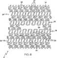
図5は、平立面図で未拡張状態のステント12を示している。図5に示すように、ステント本体14は、略セル形状を有し、ステント12の長さに沿って、所定の一般的、総合、または主パターンで構成された略反復型の一連のストラット24とコネクタ26を備えている。ストラット24は、基端部の湾曲部27で接合された一対の長手方向ストラット部25を有する。ストラット24は、先端部の湾曲部29で相互連結されて、ステント12の円周の周りに延びるリング28を形成している。一連の円周リング28はステント12の全長に沿って互いから長手方向に離間されて配置されており、コネクタ26がリング28を互いに長手方向に連結している。コネクタ26は、隣接円周リング28間に略長手方向に延びて、隣接リング28の長手方向に隣接するストラット24の各湾曲部25、29に連結している。1つの好ましい実施形態において、コネクタ26は略S字型またはジグザグ型であるが、他のパターンを用いてもよい。ステント12に用い得るパターンの詳細は、2002年10月20日に出願された同時係属PCT出願IL02/00840号にさらに詳しく説明されており、このPCT出願はそのまま本明細書に文献援用される。さらに、他の多くのストラットおよびコネクタパターンの使用も可能であり、本発明のパターンは例示目的で示されているに過ぎない。 FIG. 5 shows the
ステント12は、さらに、ステント12の長さに沿ってある個所に配置された枝部30を有する。枝部30は、体内管分岐部の枝管内に延びるように構成されたステント壁14の1区域または部分を含む。一般に、枝部30は、未拡張状態から拡張状態まで移動可能なように構成されている。枝部30は、未拡張状態では、未拡張ステント12で画定された容積内に配置されている。すなわち、枝部30はステント壁14から半径方向に突出していない。枝部30は、拡張状態では、ステント壁14から外側に延び、枝管内に拡張される。図6で最も良く分るように、枝部30は、初期には、ステント本体14の残りの部分と面一であり、同一平面内、または同円筒内に位置し、ステント本体14の残りの部分に関して外側に延び得るステント本体14のステント壁区域を含む。この関連で、枝部30は、ステント本体14の全体または主なパターン内の開口、スリット、空間、空隙、または他の不一致部分にほぼ隣接している。この配置により、拡張配置前に、ステントの枝管内へのアクセスが可能になると同時に、枝管内でステント周方向に整合させることができる。他の実施形態では、ステントに複数の枝部を組み込んで、1つ以上の管に多重アクセスさせることができる。1つの好ましい実施形態において、枝部30は、ステント12の中央部分に配置され得る。代替実施形態では、枝部30は、ステント12の長さに沿ってどこに配置してもよい。 The
図6で最も良く分るように、第一実施形態において、枝部30は、枝部リング32の一部を含み、開口34に隣接して近位に配置される。枝部30を拡張させると、枝部リング
32の開口34に隣接する部分は枝管内に延びるが、枝部リング32に隣接する円周リング28は枝管内には延びない。開口34は、枝部リング32と対向枝部リング33とを接合する少なくとも1つのコネクタ26が欠損することによって形成される。いくつかの実施形態においては、4つの隣接コネクタが欠損する。しかし、代替実施形態では、開口34を形成するために任意の数のコネクタが欠損し得る。この実施形態において、枝部リング32は形状が円周リング28と実質的に類似しており、ストラット24と実質的に類似した枝部リングストラットを有する。しかし、複数の隣接ストラットは開口34に隣接するコネクタ26がない。この関連で、枝部リング32は、枝部リング32の少なくとも一部がステント本体14に関して外側に延びるのを容易にするためにステント本体14から少なくとも部分的に分離可能である。いくつかの実施形態において、枝部リング32の構造は円周リング28に関して異なっていてもよく、枝部リングストラット36はストラット24とは異なる形状を有し得る。As best seen in FIG. 6, in the first embodiment, the
図7に示すように、ステント12を拡張させると、枝部30は枝管内に延び、枝部リング32の一部が枝管4の内面を少なくとも部分的に被覆する。したがって、1つの好ましい実施形態において、枝管内のステント被覆面積は、枝管内壁の基端側の少なくとも部分的な被覆面積を含む。 As shown in FIG. 7, when the
さまざまな代替実施形態により、枝部30の多様な構造が提供される。例えば、枝部リング32は、円周リング28に関してさまざまであってよく、枝部リングストラット36は、ストラット24とは異なる形状を有し得る。1つの代替実施形態において、枝部リングストラット36はストラット24より長い。別の実施形態では、枝部リングストラット36は、円周リング28に比べて、周方向により高密度に実装され、その結果、枝部リング32内面積当たりの枝部リングストラット36の数が多くなる。別の実施形態において、枝部リングストラット36はストラット24より細くし得る。さらに別の実施形態では、枝部リングストラット36はストラット24とは異なる材料製であり得る。 Various alternative embodiments provide various structures for the
図8を参照すると、別の代替実施形態のステント19が示されており、この実施形態において、枝部30は、円周リング28のストラット24より長く、数が多い枝部リングストラット36を有する枝部リング32を含み、結果として、枝部リング32がより高密度になっている。さらに、枝部リング32の両側の枝部リングコネクタ38の数は、枝部ストラット36当たり、ストラット24当たりのコネクタ26の数より少ない。開口34は、隣接枝部リング32の先端側にあり、少なくとも1つの、好ましくは複数の、枝部リングストラット40,42,44の先端部46はコネクタを有さず、ステント本体14から分離可能である。この実施形態では、ストラット40,42,44に側方に隣接して配置された2つの枝部リングストラット48および50はコネクタを有さない基端部52を備える。この関連で、自由基端部52は、ステント本体14に関して外側拡張時の枝部リング32の移動に対する抵抗力が弱い。この同じ手順を用いて、枝部リング中にコネクタを有さない1つ、2つ、3つまたはそれ以上の基端部を得ることができる。さらに、枝部リングコネクタ38の形状と配置はコネクタ26のものとは異なる。例えば、枝部30を体内管側枝内により深く拡張しやすくするために、枝部リング32の基端側に沿った枝部リングコネクタはコネクタ26より長い。また、枝部30を枝管内により深く拡張しやすくするために、枝部リング32の先端側に沿った枝部リングコネクタはコネクタ26とは異なるように成形、配向されている。代替実施形態において、枝部リングコネクタ38も相互に異なり得る。また、長い枝部リングストラット36は、概して、長くなったことにより撓みやすくなるので、類似の短いストラットより柔軟である。さらに、長さが増すと、拡張時に枝管により深く侵入するので、体内管壁の被覆率が高くなる。代替実施形態では、さまざまな形状および配向の枝部リングコネクタ38を用い得る。 Referring to FIG. 8, another alternative embodiment stent 19 is shown, in which the
図9を参照すると、図8の実施形態に類似した枝部30を有するが、ただし、枝部リン
グストラット40,42,44が他の枝部リングストラット36より長く、その先端部が開口34の基端側に対して弓状プロファイルを画定している別の代替実施形態のステント29が示されている。また、中央のストラット42は、ストラット42に隣接するストラット40,44より長い。この関連で、枝部30を拡張させると、ストラット40,42,44は枝管内に深く延び、図8に示す実施形態より高い体内管壁被覆率が得られる。この関連で、この実施形態は、例えば図1に示すものなどの分岐体内管における閉塞部をより容易に被覆することができ、その結果、枝管により多くの血流を流し得る。また、以下にさらに詳細に説明するように、この実施形態により、枝管における第2ステントの使用が容易になる。Referring to FIG. 9, it has a
図10を参照すると、枝部30が枝管内に延びて、枝部リング32が枝管の基端側の内面を少なくとも部分的に被覆している拡張状態の図9のステント29が示されている。枝部リング32のストラット42の先端部は、この実施形態ではストラット42が隣接ストラット40,44より長いために、ストラット40,44の先端部より深く枝管内に延びている。この関連で、枝部30を枝管内に拡張させると、枝部30の先端周辺に沿って、略テーパー、直線、または線形プロファイルが形成される。 Referring to FIG. 10, there is shown the expanded
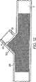
図11と図12を参照すると、管分岐部に実装された、それぞれ拡張状態の図5と図9のステント12、29の略図が示されている。図11に示すように、図8の実施形態のステント19は、枝管4内に延びると枝部30の先端周辺45に沿った略湾曲または放射状プロファイルを有する。この略湾曲または放射状プロファイルは、図8の実施形態のステント19の枝部30の特定形状に起因する。具体的に言えば、この実施形態では、枝部リング32のすべての枝部リングストラット36が等しい長さを有しているために、ストラット36の先端部は枝管4内に半径方向等距離に拡張し、それによって、枝部30の先端周辺45に沿って略湾曲または放射状プロファイルを形成する。図12を参照すると、図9の実施形態のステント29は、枝管4内に延びると、ステント枝部30の先端周辺47に沿って略テーパー、直線、または線形プロファイルを有する。図12の略直線または線形形状は、図9の実施形態のステント29の枝部30の特定形状の結果である。具体的に言えば、この実施形態では、枝部リング32の中央ストラット42がストラット42に隣接するストラット40,44より長いために、ストラット42の先端部は、図10で最も良く分るように、ストラット40,44の先端部より枝管4内に深く延びるために、枝部30の先端周辺に沿って略テーパー、直線または線形プロファイルを形成する。1つの好ましい実施形態において、線形プロファイルは、枝管4の軸線に関して直角を成す。しかし、代替実施形態では、線形プロファイルは、枝管4の軸に対して任意の角度であってよい。図12に示す枝部30の先端周辺に沿った線形プロファイルの1つの有利な特徴は、枝管4内で第2ステント51を用いる場合、線形プロファイルであれば、第2ステントと整合させやすくなり、より大きな枝管壁の表面積を被覆し得ることである。例えば、第2ステント51を図11のステント12と組み合せて用いると、放射状先端周辺45と隣接する第2ステントの直線または線形エッジとの間の接合部で2つのステント間にギャップが存在し得るのに対し、図12のステント29を用いると、緊密に当接した接合部を得ることができる。 Referring to FIGS. 11 and 12, there is shown a schematic diagram of the
図13を参照すると、図9の実施形態のものと同様な代替実施形態の枝部30を有するが、ただし、側方枝部リングストラット48および50が、他の枝部リングストラット36より長く、枝部リングストラット48,50の基端部52が基端方向に他の枝部リングストラットを越えて枝部リング32と隣接円周リング28の間の空間内に延びている別の実施形態のステント39が示されている。枝部リングストラット48,50は、コネクタがない基端部52を有し、ステント本体14に関する外側拡張時の枝部リング32移動に対する抵抗力が弱い。この関連で、長い側方枝部リングストラット48,50はヒンジと同様な機能を果たして、枝部リング部30の外側への拡張を容易にし、それによって、図
9の実施形態のステント29に比べて大きい角度11(図1)で配置された枝管に適合し得る。この場合も、ストラット40,42,44は、枝部リングストラット36より長いので、図8に示す実施形態より曲りやすく、体内管壁の被覆率が高くなる。Referring to FIG. 13, it has an
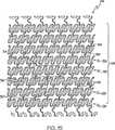
図14および図15を参照すると、ステント本体14が主パターン54とは異なるパターンの長手方向区域53を有する別の実施形態のステント49が示されている。長手方向区域53は、ストラット24およびコネクタ26より寸法は小さいが、主パターン54と類似した幾何学パターンを形成する略反復型の一連のストラット56およびコネクタ58を含む。この関連で、ストラット56がストラット24より短く、コネクタ58がコネクタ26より短いために、ストラット56はリング28内面積当たりの数が多く、リング28は区域53内面積当たりの数が多い。1つの好ましい実施形態では、同数のコネクタ58が隣接するリング28の間に延びる。しかし、長手方向区域53ではストラットの数が多いために、コネクタ58は、隣接リング28の1つおきのストラット間に長手方向に延びる。図15に示すように、ステント49は、区域53内に配置された枝部30をさらに有する。枝部30は、開口34に隣接した枝部リング32を含む。開口34は、枝部リング32と対向枝部リング33とを接合する少なくとも1つのコネクタ26が欠損することによって形成される。1つの好ましい実施形態では、2つの隣接コネクタが欠損する。しかし、代替実施形態では、開口34を形成するために、任意の数のコネクタが欠損し得る。この実施形態において、枝部リング32は形状が円周リング28と実質的に類似しており、ストラット56に実質的に類似した枝部リングストラット36を有する。しかし、複数の隣接ストラットは開口34に隣接するコネクタ58を欠き、枝部リング32は、その少なくとも一部をステント本体14に関して外側に伸ばしやすくするために、開口34でステント本体14から少なくとも部分的に分離可能である。長手方向区域53の概して小さいストラットおよびコネクタによって、ストラットおよびコネクタ材料の自由移動が可能になり、体内管壁への適合が容易になる。また、小さいストラットおよびコネクタは、枝管壁の表面積を比較的高密度に被覆するが、これは、枝管入口部の周りをより均一に被覆するのに有用であり得る。具体的に言えば、この実施形態は、比較的小さいパターンを閉塞部の周りで曲げたり、輪郭に合わせたりして、閉塞部を被覆し得るので、分岐管の幾何学的に複雑な閉塞部を被覆するのに特に有利であり得る。また、この実施形態は、小さいパターンが閉塞部の表面積をより広く被覆し得るので、比較的小さい閉塞部に有利である。 14 and 15, another embodiment of a stent 49 is shown in which the
図16を参照すると、別の実施形態のステント59が示されており、このステントは、2つの隣接円周リング28から周方向に延びる連結された3つの隣接枝部リング区域60,62,64の一部を含む代替枝部30を有する。枝部リング区域60,62,64はそれぞれ、複数の枝部ストラット66を含み、枝管コネクタ68によって長手方向に連結されている。ストラット66は、リング28のストラット24より長手方向に短く、コネクタ68はコネクタ26より小さい。先端リング60は開口34に隣接しており、リング60のストラット66の先端部は、枝部リング区域60,62,64の少なくとも一部を伸張してステント本体14に関して外側に拡張できるように、開口34でステント本体14から分離可能である。この実施形態において、3つの枝部リング区域60,62,64は外側にさらに放射状に拡張可能であり、この枝部30は入口部の基端側の形状に適合または一致させるのに特に有利であり得る。さらに、この実施形態の枝部は、図1に示すものなどの分岐体内管の閉塞部の周りにより容易に延ばしたり曲げたりできる上に、枝管壁を被覆し、かつ枝管により多くの血流を流し得る。 Referring to FIG. 16, another embodiment of a
図17および図18を参照すると、代替実施形態のステント69が示されており、このステントは別の枝部30を有する。この特定の実施形態において、枝部30は、支持ストラット70と拡張可能リング72とを有する。枝部30は少なくとも1つの側面開口74を画定する。一実施形態において、側面開口74を画定するセルの寸法は、(ステント拡
張前の)側面開口74はステント本体14の他の開口より大きくされている。側面開口74の存在は、概して、サイドシースを収容し、医師が処置中または処置後に枝管にアクセスできるように構成される。図18に示すような1つの特定の実施形態において、側面開口74は、連続材料からなる拡張可能リング72で取り囲まれている。代替実施形態では、拡張可能リング72は、結合されていない複数の部分、または側面開口74の一部分だけを被覆する1つの部分からなる。一連の支持ストラット70は、拡張可能リング72をストラット24およびコネクタ26と連結している。支持ストラット70は、拡張時には少なくとも部分的にまっすぐになり、拡張可能リング72を枝管内に突出させる折りたたみパターンまたは巻き形状パターンを有することが好ましい。Referring to FIGS. 17 and 18, an alternative embodiment stent 69 is shown, which has another
この実施形態では、図18に示すように、ステント69を拡張させると、枝部30は枝管内に延び、拡張可能リング74が枝管の内面を少なくとも部分的に被覆する。したがって、1つの好ましい実施形態において、枝管の一部のステント被覆面積は枝管内壁の全周を含む。代替実施形態においては、部分被覆または数被覆部分が存在する。 In this embodiment, as shown in FIG. 18, when stent 69 is expanded,
図19〜図21を参照すると、主ステント本体14と枝部30の別の実施形態とを有する別の実施形態のステント79が示されている。図19および図20は、枝部30が拡張配置されていない未拡張状態のステント79を示している。図21は、枝部30が拡張された拡張形状のステント79を示している。図に示すように、主ステント本体14は、リング28とコネクタ26の略反復型パターンを有する主ステントパターンを含む。枝部30とそれを取り囲む中央区域80は、ステント79のリング28とコネクタ26の反復型パターンの間を中断している。この実施形態において、枝部30は、1つの好ましい実施形態では、枝部30が拡張形状で枝管の内壁の全周辺または円周に接触するように、枝管内にその長手軸線に関して半径方向に拡張可能かつ長手方向に拡張可能なように構成されている。この関連で、枝部30は、枝管壁を360度被覆することが好ましい。すなわち、枝部30は、体内管に接触するように(それによって、体内管サイズに関して調整可能であるように)ステント79の長手軸線81に関して外側に拡張可能であると共に、軸線83の周りに半径方向に拡張可能である。 19-21, another embodiment of a
図20を参照すると、ステント79の区域80の拡大図が示されている。1つの好ましい実施形態においては、主ステント本体14と枝部30との間の遷移部として構造支持部材84が設けられ得る。1つの好ましい実施形態の一態様において、構造支持部材84は、主管に対してある角度で延びる枝管に適合するように楕円形であり得る。代替実施形態では、脈管構造に適合させるために他の形状の支持部材84を用い得る。構造支持部材84は連続リングを含み得る。この実施形態において、構造支持部材84は、非拡張型の完全なリングであり、特定の円周を越えて半径方向に拡張することはない。 Referring to FIG. 20, an enlarged view of the
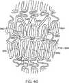
図19および図20に示すように、構造支持部材84内には、2つの同心リング、すなわち、内側リング86と外側リング88が配置され、ステント79が未拡張状態のときに側枝管にアクセスできるように略円形の中央枝部開口34を取り囲んでいる。リング86,88は、複数の内側コネクタ90によって相互連結されている。外側リング88は、複数の外側コネクタ92によって構造支持部材84に連結されている。リング86,88は略曲線部材である。例えば、リング86,88は、波形の花弁状部、突起、またはピーク94を特徴とし得る。1つの好ましい実施形態において、各リング86,88は、同数の波形ピーク94を有するが、内側リングは、図に示すように、より接近または密集させて配置し得る。別の好ましい実施形態において、各リング86,88は、8つの花弁状部または波形ピーク94を有するが、代替実施形態では、各リングは、任意の数の波形ピークを有していてよく、ピークの数は各リング毎に同じである必要はない。波形ピーク94は、通常、湾曲部98によって相互連結された一対のストラット部96を有し、それらのストラット部自体は、別の湾曲部で隣接ストラット部に連結されている。1つの好ましい実
施形態においては、構造支持部材84と外側リング88との間には8つの外側コネクタ92が延びており、各外側コネクタ92は、一端が外側リング88のストラット部96のほぼ中央に、また他端が構造支持部材84に取り付けられている。図に示すように、外側コネクタ92も波形形状を有し得るが、代替実施形態では、外側コネクタ92は異なる形状を有し得る。この好ましい実施形態の別の態様において、外側コネクタ92は、構造支持部材84の周りに等間隔または対称配置され得る。内側リング86は、複数の内側コネクタ90によって外側リング88に取り付けられており、1つの好ましい実施形態では、8つの内側コネクタ90がリングを連結する。内側コネクタ90は、外側リング88の湾曲部98から内側リング86の湾曲部まで延びている。図20に示すように、1つの好ましい実施形態において、内側コネクタ90は単純湾曲形状を有する。求める結果に応じて、他の量、形状、サイズおよび配置のコネクタ、リングおよび間隔を用い得る。コネクタを変更すると、異なる量の柔軟性と被覆面積が得られる。示されている形態タイプのリングおよびコネクタは、枝管の被覆率はもとより枝部30の半径方向および長手方向における拡張の必要性に対処する。本発明に従って枝部の他の形状および配置を用い得る。As shown in FIGS. 19 and 20, two concentric rings, an
再度図19および図20を参照すると、枝部を取り囲むステントパターンは、上述の実施形態すべてが可能であるように、枝部30に適合させるために異なるパターンにするように変更され得る。具体的に言えば、中央区域80内のリング28は、枝部30が占める面積を補うのに十分な被覆率と柔軟性を得るために、より密になるような構成および寸法にされ得る。 Referring again to FIGS. 19 and 20, the stent pattern surrounding the branch can be altered to be a different pattern to fit the
図21を参照すると、ステント79は、枝部30が拡張配置された拡張形状で示されている。枝部30を拡張すると、内側および外側リング86,88は、長手枝部軸線83の周りに移動し、主ステント本体14から離れて側方に枝管内に拡張して、枝管被覆部を形成する。拡張時、外側コネクタ92は外側に移動し、内側コネクタ90は長手枝部軸線83にほぼ平行な位置へとまっすぐされ得る。1つの好ましい実施形態において、拡張リング86,88は、実質的に同じ拡張径を有するが、代替実施形態では、先が細くなった体内管に適合させるために、例えばテーパーバルーンを用いる場合には、リング86,88は異なる直径を有するようにすることも可能である。枝部30は、治療する枝管の形状に応じて、ステントの長手軸線81に対してさまざまな角度で拡張させることができる。この実施形態では、枝部30は、約1.5〜3mm枝管内に延びることが好ましい。 Referring to FIG. 21, the
図22を参照すると、主ステント本体14と枝部30の別の実施形態とを有する別の実施形態のステント89が示されている。ステント89は、2つの同心リング86,88構造を取り囲む不連続な支持部材104を有すること以外は、ステント79と実質的に類似している。支持部材104は、略楕円形状を有し、周辺に沿って複数の切れ目106を備える。不連続な支持部材の形状により、拡張時の枝部の柔軟性が高められ、一般に、より広範囲の枝管構造に適合させることができる。1つの好ましい実施形態の一態様において、構造支持部材84は、主管に対してある角度をなして延びる枝管に適合させるために楕円形であり得る。 Referring to FIG. 22, another embodiment of a stent 89 having a
図23および図24を参照すると、それぞれ未拡張状態および拡張状態の別の実施形態のステント99が示されている。ステント99は、主ステント本体14と別の実施形態の枝部30とを有する。ステント99はステント79と実質的に同様であるが、ただし、2つではなく3つの同心リング110,112,114を取り囲む支持部材108を含む枝部30を有する。図24で分るように、ステント99を拡張させると、この実施形態の3つの同心リング構造は、別の同心リングを加えることによって枝部30に該してより高密度のパターンが形成されるために、枝管壁のさらなる支持を容易にする。 Referring to FIGS. 23 and 24, another embodiment of a
図34を参照すると、主ステント本体14と別の実施形態の枝部30とを有する代替実
施形態のステント220が示されている。図34は、枝部30がまだ拡張配置されていない未拡張状態で示されているステント220の平面図である。主ステント本体14は、リング28とコネクタ26の略反復型パターンを有する主ステントパターンを含む。枝部30とそれを取り囲む中央区域80は、ステント220のリング28とコネクタ26の反復型パターンを中断している。枝部30は、未拡張形状で枝管の内壁の周辺または円周全体に接触するように枝管内に拡張できるように構成されている。Referring to FIG. 34, an
1つの好ましい実施形態では、主ステント本体14と枝部30との間の遷移部として構造支持部材224を設け得る。支持部材224は、間に空間246を挟んで対向関係に配置された略楕円形半部分を備える。支持部材224は、2つの同心リング228,230構造と、1つの中心枝部開口232とを取り囲んでいる。枝部開口232は、ステント220が未拡張状態にあるときに側枝管へのアクセスを提供し、開口232を介してサイドシースが通過し得る。リング228および230は、複数の内側コネクタ234によって相互連結されている。外側リング230は複数の外側コネクタ236によって構造支持部材224に連結されている。リング228,230は、略曲線部材であり、波形の花弁状部、突起、またはピーク238を有する。この実施形態において、外側リング230は内側リング228より多数のピークを有する。8つの外側コネクタと8つの内側コネクタが支持部材224とリング228,230を相互連結することが好ましい。この実施形態において、内側および外側コネクタ234,236は、略直線部材であり、枝部30の中心に向かって延びるように半径方向に整合していることが好ましい。操作時、外側コネクタ236と支持部材224との交差点は、その周りに、花弁状部238を側枝管内に外側に開くかまたは旋回させ得る旋回点を形成する。1つの好ましい実施形態において、略直線内側および外側コネクタは、花弁状部238が花のように開くように一緒に旋回する。 In one preferred embodiment, the structural support member 224 may be provided as a transition between the
図35を参照すると、代替実施形態の枝部30を有する代替実施形態のステント240が示されている。ステント240は、主ステント本体14と枝部30の間の遷移部として構造支持部材244を有する。支持部材244は、間に空間246を挟んで対向関係に配置された略楕円形半部分を含む。支持部材244は、2つの同心リング248,250構造と中心枝部開口252とを取り囲んでいる。リング248,250は、複数の内側コネクタ254で相互連結されている。外側リング248は、複数の外側コネクタ256によって構造支持部材244に連結されている。リング248,250は、略曲線部材であり、波形の花弁状部、突起、またはピーク258を有する。リング248,250の間には、補助アクセス開口255が割って入って、ステント240が未拡張状態のとき、側枝管へのアクセスを提供する。補助アクセス開口255の近くの外側コネクタ256間にリング部257が延びている。この実施形態において、補助アクセス開口255は、通例、サイドシースをより容易に受容し、側枝にアクセスしやすくするために、中央枝部開口252より大きい。補助アクセス開口255は、ステントデリバリーシステム上に取り付けられているときには中央枝部開口252の近くに配置することが好ましいが、代替実施形態では、さまざまな位置に配置され得る。図36には、ステント240と同様であるが、空間246を通って延び、枝部30の外側で外側リング250とストラット264とを側方に連結する側方連結部材262をさらに備えた代替実施形態のステント260が示されている。この関連で、枝部30を側枝内に拡張させると、ストラット264は半径方向内側に引っ張られて入口部の円周を支持する。この追加構造により、半径方向強度が高められ、体内管壁への支持が強化される。 Referring to FIG. 35, an
上記実施形態のいずれにおいても、枝部30は、ステントを完全拡張すると、枝管内に突出する。拡張時、枝部は、用途に応じてさまざまな長さで枝管内に延び得る。拡張量は約0.1〜10.0mmの範囲でさまざまであり得る。1つの好ましい実施形態において、拡張長は1〜3mmである。別の好ましい実施形態において、拡張長は約2mmである。代替実施形態では、枝管内への拡張量は、枝部30のさまざまな円周セグメントに合わ
せて変えられる。各実施形態で示すように、枝部は、幅が約2.5mm、長さが約2.5〜3.0mmである。しかし、枝部は、さまざまなサイズの枝管に適合するような寸法を有し得る。枝部は、例えば楕円形または円形を含めた、枝管に適合する任意の管状形状を有し得る。In any of the above embodiments, the
一般に、上述のステント実施形態には、多様なデリバリーシステムおよび拡張配置法を用い得る。例えば、挿入にはカテーテルシステムを用い、ステントは、バルーン拡張式もしくは自己拡張式であるか、ステントはバルーン拡張式、枝部は自己拡張式、またはその逆であり得る。ステントを主管に配置し、枝部を側枝と整合させたら、ステントを拡張させ得る。ステントがバルーン拡張式の場合、ステントは、1回の拡張または多重拡張で拡張させ得る。具体的に言えば、ステントは、例えば、米国特許第6,325,826号および同第6,210,429号に記載のようなバルーンカテーテルおよびサイドシースを有するステントデリバリーシステムで拡張配置可能であり、上記特許はそのまま本明細書に文献援用される。1つの好ましい実施形態においては、一方のバルーンはステントを拡張させるように構成し、他方のバルーンは枝部30を拡張させるように構成したキッシングバルーン法を用い得る。ステントの主部を主管で拡張させた後、ステントデリバリーシステムを抜去し、枝部の側穴に第2バルーンを通し、膨脹させてステントの枝部を拡張させ得る。1つの代替実施形態では、同じバルーンを主管に挿入して膨脹させ、収縮させてから、枝管内に挿入し、次いで、再膨脹させて枝部30を拡張させ、枝管内に突出させる。あるいは、ステントを2つのバルーン上でデリバーし、主部と枝部を同時に拡張させることができる。必要に応じ、枝部を別のバルーンまたは複数のバルーンでさらに拡張させ得る。さらに別の代替法は、主部と枝部を同時に拡張させ得る特殊形状のバルーンを用いる方法である。ステントは、他のタイプのステントデリバリーシステムで拡張配置することもできる。あるいは、ステントまたはステント部分を自己拡張性材料で製造することも可能であり、拡張は、ステントまたはその少なくとも枝部30に、例えば、ニチノール、コバルトクロムなどの自己拡張性材料を用いるか、従来技術では周知の他の記憶合金を用いることにより達成し得る。 In general, a variety of delivery systems and expansion methods can be used with the stent embodiments described above. For example, a catheter system may be used for insertion and the stent may be balloon-expandable or self-expandable, the stent may be balloon-expandable, the branch is self-expandable, or vice versa. Once the stent is placed in the main tube and the branch is aligned with the side branch, the stent can be expanded. If the stent is balloon expandable, the stent can be expanded in a single expansion or multiple expansions. Specifically, the stent can be expanded with a stent delivery system having a balloon catheter and side sheath as described, for example, in US Pat. Nos. 6,325,826 and 6,210,429. The above patent is incorporated herein by reference in its entirety. In one preferred embodiment, one balloon may be configured to expand the stent and the other balloon may use a kissing balloon technique configured to expand the
本発明の目的に適したカテーテルの構成および操作は、1999年6月4日出願の米国特許出願番号09/325,996号および1999年12月6日出願の米国特許出願番号09/455,299号の一部継続出願である2000年7月11日出願の米国特許出願番号09/614,472号の一部継続出願である2000年9月15日出願の米国特許出願番号09/663,111号に詳細に記載されており、上記出願のいずれの開示も本明細書に文献援用される。上記出願で教示されているカテーテルは例として役立つものであり、本願のステントに適した他のカテーテルも本願の範囲内に包含されることに留意すべきである。代替実施形態では、バルーンを搭載していないカテーテルを使用し得る。例えば、ステントがニチノールもしくはコバルトクロムなどの記憶合金からなるか、機械的自己拡張式ステントである場合、必ずしもバルーンがカテーテルに搭載されるとは限らない。さらに、本発明のステントの配置には、本明細書に開示されていないものを含めた任意の他のカテーテルを使用し得る。 The construction and operation of catheters suitable for the purposes of the present invention are described in US patent application Ser. No. 09 / 325,996 filed Jun. 4, 1999 and US Patent Application No. 09 / 455,299 filed Dec. 6, 1999. No. 09 / 663,111, filed Sep. 15, 2000, which is a continuation-in-part of US patent application Ser. The disclosures of any of the above applications are incorporated herein by reference. It should be noted that the catheters taught in the above application serve as examples, and other catheters suitable for the present stent are also included within the scope of the present application. In an alternative embodiment, a catheter without a balloon may be used. For example, if the stent is made of a memory alloy such as nitinol or cobalt chrome or is a mechanical self-expanding stent, the balloon is not necessarily mounted on the catheter. Furthermore, any other catheter, including those not disclosed herein, can be used to deploy the stent of the present invention.
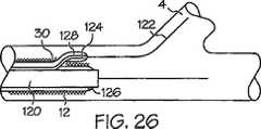
図25〜図28を参照すると、本発明のステントの使用法における一実施例の工程が図解されている。一例として、この方法はステント12を利用して示されている。そのようなカテーテルシステムを管内に配置する方法およびそのようなシステムを分岐部またはその近くに配置する方法は、2002年12月17日出願の同時係属米国特許出願番号10/320,719号にさらに詳細に説明されており、同出願はそのまま本明細書に文献援用される。図25に示すように、任意の公知方法を用いてカテーテルシステム120を分岐部の近位に配置する。次いで、図26に示すように、ステントの開口を介して枝管ガイドワイヤ122を進める。1つの好ましい実施形態において、前記開口は、上述のように、例えば、いくつかのコネクタ26の欠損によって形成された開口などの指定された側枝
開口であり得る。枝部30は開口に隣接している。図27に示すように、主カテーテル120にサイドシース124が取り付けられている場合には、主カテーテル120と一緒にサイドカテーテル124を進める。あるいは、サイドシース124が主カテーテル120から分離している場合には、第2カテーテルまたはサイドシース124を独立してステントの開口を介して枝管内に進める。サイドシース124を枝管4内に挿入すると、枝部30は、枝管4の管腔の一部を覆って配置される。次いで、図28を参照すると、主カテーテル120上に位置する第1バルーン126を膨らませると、ステント本体が拡張し、さらに第2カテーテルまたはサイドシース124上に配置された第2バルーン128を膨らませると、枝部30がステント本体に関して外側に押し付けられ、ステントが枝管の少なくとも一部を被覆する。次いで、両バルーンを収縮させてから、カテーテルシステムおよびガイドワイヤを抜去する。Referring to FIGS. 25-28, the steps of one embodiment in the use of the stent of the present invention are illustrated. As an example, this method is illustrated utilizing a
図29〜図31を参照すると、本発明のステントの別の使用法の工程が図解されている。一例として、この方法はステント12を利用して示されている。示されている方法は、ヘルニア様の脱出部分を有するバルーン(herniated balloon 、以下「脱出バルーン」と
称する)(図32)を備えた主カテーテル131を有するカテーテルシステムを用いて達
成し得る。具体的に言えば、このステントは、例えば、2003年7月18日出願の米国特許出願番号60/488,006号に記載されているような突出部を有するバルーンを備えたステントデリバリーシステムで拡張配置することができる。上記出願はそのまま本明細書に文献援用される。図29に示すように、カテーテル131は突出部137を有するバルーン135を搭載しており、突出部137はバルーンの円筒形外面134から外側に突出している。Referring to FIGS. 29-31, another usage process of the stent of the present invention is illustrated. As an example, this method is illustrated utilizing a
図32を参照すると、拡張状態で示されている脱出バルーン135は、略円筒形状を有し、突出部137は、膨脹時、本発明の原理に従って、バルーンの外面134から外側に移動するバルーンの任意の付属物または一体部分であり得る。1つの好ましい実施形態において、突出部137は、略円筒形状を保持するバルーンの他の部分より大きい拡張性を有するバルーン壁の一部である。別の実施形態では、突出部137は、バルーン壁に取り付けられた一体構造物であり得る。突出部137は枝部30を拡張配置するのに好ましい任意の形状を有し得る。1つの好ましい実施形態において、突出部137は半球形状を有する。別の好ましい実施形態では、突出部137は卵形形状を有する。使用時、突出部137が枝部に配置されるようにステント12をバルーン135上に緊縮される。図に示すように、突出部137は枝部30の半径方向内側に隣接してまたは平行に配置する。脱出バルーン135は、拡張可能な対して側方外側方向に力を加えてこれらの要素を側枝4の方向に偏向させることにより、枝部30を拡張させたり、かつ/またはステント12の外側に展開可能な構造を展開するのに用いられる。突出部137は、バルーンの長さに沿って任意の位置に配置され得る。例えば、突出部137は、ステントの中央1/3上に配置し得る。 Referring to FIG. 32, the
一実施形態において、バルーンは複合材料から構成し得る。例えば、エラストマー材料と半または非弾性材料との組み合せ、例えば、ウレタン、シリコーン、およびラテックス、(エラストマー)ポリエチレン、ハイトレル、ペバックス、ポリアリールエーテルエーテルケトン、ポリオキシメチレン、ポリアミド、ポリエステル、熱可塑性ポリエーテルエーテルケトンおよびポリプロピレン(半〜非弾性)を使用し得る。バルーンは、上記材料と、例えばケブラールや、シルクコットン、ウールなどの織布とを組み合せて構成してもよい。この構成において、織物は、所望の脱出バルーンの形状を有するロッド上に巻き付けるか編み込んでから、ロッド上にポリマーを押出またはディップコートする。複合材料を、硬化、ヒートセット、または接着融合させる。次いで、ロッドを抜去すると、残った形状が脱出バルーンとなる。バルーンは、成形カラーを用いるか、バルーン表面に物体を接着結合させるか、または脱出部もしくは突出部を形成する大量の接着剤を用いて、従来
型バルーンに付属物を加えることにより構成することもできる。1つの代替実施形態において、バルーンは、3つの小型バルーンを成形し、それらを中央のバルーンが丸い形になるように長手方向に並べて取り付けることにより構成し得る。バルーンは、共通のインフレーションポートを共有するであろう。バルーンを膨らませると、中央のバルーンが脱出部になる。In one embodiment, the balloon may be composed of a composite material. For example, combinations of elastomeric and semi-elastic materials such as urethane, silicone, and latex, (elastomer) polyethylene, Hytrel, Pebax, polyaryletheretherketone, polyoxymethylene, polyamide, polyester, thermoplastic polyether Ether ketone and polypropylene (semi-inelastic) can be used. The balloon may be configured by combining the above materials with a woven fabric such as Kevlar, silk cotton, wool, and the like. In this configuration, the fabric is wrapped or knitted onto a rod having the desired escape balloon shape before the polymer is extruded or dip coated onto the rod. The composite material is cured, heat set, or adhesively fused. Next, when the rod is removed, the remaining shape becomes the escape balloon. Balloons can also be constructed by adding appendages to a conventional balloon, using a molded collar, adhesively bonding an object to the balloon surface, or using a large amount of adhesive that forms an escape or protrusion. it can. In one alternative embodiment, the balloon may be constructed by shaping three small balloons and attaching them longitudinally side by side so that the central balloon is round. Balloons will share a common inflation port. When the balloon is inflated, the central balloon becomes the escape section.
再度図29〜図31を参照すると、突出部137は、ステントの開口内に直接嵌合するように構成され得る。図29に示すように、カテーテル131をガイドワイヤ131の上を伝って進め、分岐部の近位に配置する。図30に示すように、バルーンの突出部137が分岐部に配置されるまでカテーテルを進める。一実施形態において、突出部137は、分岐部と実際に接触するようになるのに十分なほどカテーテル131から外側に突出し、それゆえ、枝管4と整合する方法を提供する。最後に、図31に示すように、バルーン135を膨らませると、同時にステントが拡張して、枝部30が枝管4の方向に押し付けられる。バルーンを膨らませると、脱出部137が膨脹し、枝部30を介して側枝方向に延び、閉塞された側枝動脈の入口を開放する。 Referring again to FIGS. 29-31, the
1つの代替法において、ステントは脱出バルーンおよびデュアルルーメンデリバリーシステムを用いて搬送され得る。このシステムは、同心ガイドワイヤルーメンとバルーンインフレーションルーメンを含む第1ルーメンを画定する主カテーテルと、主カテーテル上の上述のような脱出バルーンと、ガイドワイヤルーメンを有するサイドシースと、ステントとを備える。ステントは、主カテーテル、バルーンおよびサイドシース上に緊縮されており、サイドシースは枝部開口または側孔を介してステントから退出する。サイドシースの先端部はステントの枝部開口と枝管4とを整合させるのに用いられる。 In one alternative, the stent can be delivered using an escape balloon and a dual lumen delivery system. The system includes a main catheter defining a first lumen including a concentric guidewire lumen and a balloon inflation lumen, an escape balloon as described above on the main catheter, a side sheath having a guidewire lumen, and a stent. The stent is crimped over the main catheter, balloon and side sheath, and the side sheath exits the stent through a branch opening or side hole. The tip of the side sheath is used to align the branch opening of the stent with the
別の実施形態において、付属部または脱出部は、例えば図33に示すシステム138などのデリバリーシステムの第2カテーテルまたはサイドシース上に配置され得る。この場合、システムは2バルーンシステムである。小さい方のバルーン140は、脱出部と同じようにステントに配置し得る。付属部または脱出部は、インフレーションルーメン141と、枝管4に配置するためのガイドワイヤ142を受容するルーメンとを有し得る。 In another embodiment, the appendage or escapement may be placed on a second catheter or side sheath of a delivery system such as, for example,
図37〜図38を参照すると、本発明の別の実施形態のステント312は、長手軸線316に沿って基端部320から先端部322まで延びるステント本体または壁314を有する。ステント壁314は、外面と、内面すなわちルーメン318を画定する下面を有する。ステント312は、ステントを半径方向に拡張させて主管を支持するために未拡張状態から拡張状態に半径方向に拡張可能である。ステント本体314は、未拡張状態では、第1容積を有するルーメン318を画定し、拡張状態では、第1容積より大きい第2容積を有するルーメン318を画定する。 With reference to FIGS. 37-38, another embodiment of the
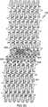
図37は、平面図で未拡張状態のステント312を示している。図37に示すように、ステント本体314は、ステント312の長さに沿って所定の主パターンで構成された略反復型の一連のストラット324およびコネクタ326を有する。以前の実施形態で説明したように、ストラット324は、基端湾曲部327で接合された一対の長手方向ストラット部325を有する。ストラット324は、先端湾曲部329で相互連結されて、ステント312の周に沿って延びるリング328を形成している。一連の円周リング328は、ステント312の全長に沿って長手方向に離間されて配置されており、コネクタ326がリング328を長手方向に相互連結している。コネクタ326は、隣接する円周リング328の間に略長手方向に延びて、隣接リング328の長手方向に隣接するストラット324の各湾曲部327,329に連結している。 FIG. 37 shows the
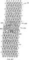
ステント312はさらに、その長さに沿ってある個所に配置された枝部330を有する
。以前の実施形態で説明したように、枝部330は、管分岐部の枝管入口部内に延びるように構成されたステント壁314の一つの区域または部分を含む。一般に、枝部330は、未拡張位置から拡張位置に移動可能なように構成されている。未拡張位置では、枝部330は、未拡張ステント312によって画定された容積内に配置されている、すなわち、枝部330はステント壁314から半径方向に突出していない。拡張位置では、枝部330は、ステント壁314から外側に延び、枝部330は枝管内に拡張される。図38で最も良く分るように、枝部330は、初期には、ステント本体14の残りの部分と面一であるか、同一平面に位置するか、または同一円筒上に位置し、ステント本体314の残りの部分に関して外側に拡張し得るステント本体のステント壁区域を含む。The
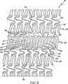
図38で最も良く分るように、一実施形態の枝部330は、枝部リング334の一部に連結された基端側枝部332と、先端側に隣接する円周リング338の開口337内に延びる先端側枝部336とを含む。この実施形態において、先端側枝部336はリング338に接続されていない。しかし、代替実施形態では、先端側枝部はリング338に接続し得る。枝部330を拡張すると、基端側枝部332と先端側枝部336は枝管内に延びるが、枝部リング334の先端側に隣接する円周リング338は枝管内には延びない。この実施形態において、枝部330は、先端側の枝部ストラット340,342,344の列が基端側の枝部ストラット350,352,354から先端方向に同調して偏位されるか、または離間されて配置された略開放ストラット形状をなす変形ストラット構造を有する。この実施形態において、先端側枝部ストラット列は略「W字」形状を有し、この枝部ストラットは、例えば、先端側枝部ストラット340,342,344の長手方向部分、例えば347を相互連結している各先端湾曲部341,343,345を有する。先端側枝部ストラット340,342,344は、湾曲部349,351によって基端部で相互連結されている。側方外側の先端側ストラット340,344は側方外側の基端側ストラット350,354の先端湾曲領域360,362に連結されており、それゆえ、先端側枝部ストラット340,342,344と基端側枝部ストラット350,352,354の間で単一の接合空間または開口364を画定している。代替実施形態では、枝部330は、さまざまな構成と形状の基端側枝部332および/または先端側枝部336を有し得る。例えば、代替実施形態において、先端側枝部のストラットの数は、基端側枝部のストラット数とは異なり得る。また、代替設計では、基端側枝部ストラットと先端側枝部ストラットのサイズや形状もさまざまであり得る。 As best seen in FIG. 38, the
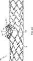
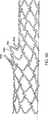
図39〜図42を参照すると、ステント312の1つの例示的デリバリー法の工程が図解されている。図39に示すように、任意の周知方法を用いて、カテーテルシステム370を主ガイドワイヤ371の上を伝って分岐部の近位に配置し、枝部330を枝管4の入口部に隣接して配置する。次いで、図40に示すように、開口364を介してサイドシースまたは枝管ガイドワイヤ372を枝管4内に進める。次いで、図41に示すように、開口364を介して第2カテーテルまたはサイドシース372を枝管内に進める。サイドシース372を枝管4内に挿入すると、枝部330は枝管4の管腔の一部を覆って配置される。次いで、ステント312を拡張させてステント本体を拡げ、枝部330をステント本体に関して外側に第1拡張位置に拡げる。1つの好ましい実施形態では、ステントの拡張に、主カテーテル370上に搭載されたバルーン376を用い得る。一実施形態において、バルーン376は、枝部330に隣接配置された拡張可能な突出部374を有する脱出バルーンまたは円筒バルーンとディンプルバルーンの組み合せであり得る。ステント312を拡張させると、先端側枝部ストラット340,342,344と基端側枝部ストラット350,352,354とを含む枝部330は、湾曲領域364,366で旋回し、その結果、枝部330の先端部はステント本体314の残りの部分から外側に枝管内に延び得る。枝部330が第1拡張位置にあるとき、ステントは枝管の少なくとも一部を被覆する。具体的に言えば、枝部330の一部は、枝管の内面、例えば、枝管壁の近位側を少なくとも部分的に被覆する。次いで、バルーンを収縮させ、枝部330をさらに図42に示
す第2拡張位置に拡張させ得る。具体的に言えば、枝部330は、先端側枝部ストラット340,342,344を湾曲領域360,362の周りに内側に旋回させ、その基端湾曲部349,351を外側側方の先端湾曲部341および345の周りに下向きに旋回させることにより、第2拡張位置に拡張させ得る。図42の完全拡張図で最も良く分るように、この第2拡張位置では、先端側枝部ストラット340,342,344は、基端側枝部ストラット350,352,354の反対側の枝管壁を支持するために、基端側枝部ストラットから離間されて配置されている。第2拡張位置では、基端側枝部ストラット350,352,354の外面が枝管壁に接触し枝管壁を支持し、先端側枝部ストラット340,342,344の下面が基端側枝部ストラットの反対側の枝管に接触してその枝管を支持することが分るであろう。この関連で、好ましくは基端側枝部ストラットが枝管壁の近位部を被覆して支持し、先端側枝部ストラットが枝管壁の遠位部を被覆して支持するように、枝管壁の周囲全体がステントで被覆され得る。枝部330を第2拡張位置まで拡張させたらば、カテーテルシステムとガイドワイヤを抜去する。Referring to FIGS. 39-42, one exemplary delivery method step of the
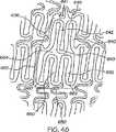
図43〜図44を参照すると、代替ステント412と枝部430が示されている。枝部330を拡張すると、基端側枝部432と先端側枝部436は枝管内に延びるが、枝部リング434と先端方向に隣接する円周リング438は枝管内には延びない。この実施形態において、枝部430は形状が上述の枝部330に類似している。しかし、先端側枝部436は単一コネクタ470によって先端方向に隣接するリング438に接続されている。コネクタ470は、先端側枝部ストラット440,442,444の少なくとも1つをリ
ング438に接続している。この実施形態において、コネクタ470は、リング438と、先端側枝部ストラット440,442,444を相互連結する基端湾曲部449,451の1つとを連結している。操作時、枝部430は枝部330とほとんど同じ方法で拡張させるが、但し、コネクタ470に隣接する先端側枝部の一部は、少なくとも部分的に第1拡張位置に対して外側の拡張に抵抗し、先端側枝部は、コネクタ470が枝部ストラットと接触する接合部または個所に関して外側に回転し得る。この第2拡張位置で、コネクタ470は、主管が枝管と交わる体内管壁の入口部または遷移領域の一部を接触支持することが好ましい。43-44, an alternative stent 412 and
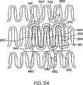
図45〜図46を参照すると、代替ステント512および枝部530が示されている。枝部530がステント本体514から外側に拡張すると、基端側枝部532および先端側枝部536は枝管内に延びるが、枝部リング534および先端方向に隣接する円周リング538は枝管内に延びない。この実施形態では、枝部530は形状が上述の枝部430と類似している。しかし、先端側枝部536は一対のコネクタ570,572によって先端方向に隣接する円周リング538に接続されている。コネクタ570,572は、先端枝部ストラット540,542,544の少なくとも1つを円周リング538と長手方向に連結している。この実施形態において、コネクタ570,572は、リング538を、先端枝部ストラット540,542,544を相互連結している基端湾曲部549,551に連結している。操作時、枝部530は枝部430とほとんど同じ方法で拡張されるが、但し、両コネクタ570,572に隣接する先端側枝部の一部は、少なくとも部分的に第1拡張位置に対して外側の拡張に抵抗し、先端側枝部は、コネクタ570,572が枝部ストラットと接触する接合部または個所に関して外側に回転し得る。この第2拡張位置で、コネクタ570,572は、主管が枝管と交わる体内管壁の入口部または遷移領域の一部を接触支持することが好ましい。 Referring to FIGS. 45-46, an alternative stent 512 and
図47〜図48を参照すると、代替ステント612および枝部630が示されている。この実施形態において、枝部630は上述の枝部330と形状が類似している。しかし、基端側枝部632と先端側枝部636はそれぞれ2つの枝部ストラットしか有していない。この実施形態において、枝部630は、1列の先端側ストラット640,642が基端側ストラット650,652から先端方向に一致して偏位されているか、または離間され
て配置された略開放ストラット形態をなす変形ストラット構造を有する。この実施形態では、先端側枝部ストラット640,642列は、基端側枝部ストラット650,652と同様なサイズ、形状および形態を有する。先端側枝部ストラット640,642は、湾曲部649によって基端部で相互連結されている。先端側ストラット640,642の外側側方部は、基端側ストラット650,652の外側側方部の基端湾曲領域660,662に連結され、それゆえに、先端側枝部ストラット640,642と基端側枝部ストラット650,652との間で単一の接合空間または開口664を画定している。操作時、枝部640を拡張させると、先端側枝部ストラット640,642および基端側枝部ストラット650,652は湾曲領域660,662において旋回し、その結果、枝部630の先端部はステント本体614の残りの部分から外側に枝管内に延び得る。枝部630が第1拡張位置にあるとき、ステントは枝管の少なくとも一部を被覆する。枝部630は、先端側枝部ストラット640,642を湾曲領域660,662の周りで内側に旋回させ、基端湾曲部649を先端湾曲部641,645の周りに下向きに旋回させることにより第2拡張位置に拡張させ得る。この第2拡張位置において、枝部ストラット640,642は、基端側枝部ストラット650,652の反対側の枝管壁を支持するために、基端側枝部ストラットから離間されて配置されている。47-48, an alternative stent 612 and
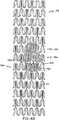
図49〜図50を参照すると、代替ステント712および枝部730が示されている。この実施形態において、枝部730は上述の枝部330と形状が類似している。しかし、外側側方の基端側枝部ストラット750,754は、他の枝部リングストラットを越えて基端方向に延び、枝部リング734と基端方向に隣接する円周リング728との間に位置する湾曲領域766,768で隣接ストラットに連結している。この関連で、長い側方基端側枝部ストラット750,754は、ヒンジと同様な機能を果たし、枝部730をさらに外側に拡張しやすくする。他の実施形態に関して上述したように、操作時、枝部730は、ステント本体714に関して外側に延びるように構成されている。枝部730は、完全拡張させると、内側枝管壁の近位側と遠位側とを少なくとも部分的にステント被覆し得る。具体的に言えば、枝部730は湾曲領域766,768で旋回可能であり、その結果、枝部730は、ステント本体714の残りの部分から外側に枝管内に延びた第1位置になって、枝管壁の一部を支持する。枝部730は、先端側枝部ストラット740,742,744を湾曲領域760,762の周りに内側に旋回させ、基端湾曲部749,751を外側側方の遠位湾曲部741および745の周りに下向きに旋回させることにより、さらに第2位置に拡張させ得る。この第2拡張位置では、枝部ストラット740,742,744は、基端側枝部ストラット750,752,754の反対側の枝管壁を支持するために、基端側枝部ストラットから離間されて配置される。第2拡張位置では、基端側枝部ストラット750,752,754の外面が枝管壁に接触し枝管壁を支持し、先端側枝部ストラット740,742,744の下面が枝管壁に接触し枝管壁を支持することが分るであろう。ステント712は、ステント312に関して上述したものと同様な方法で搬送可能であり、枝部730は、枝部330と同様な方法で拡張され得る。具体的に言えば、枝部は、開口764を介して延びる第2カテーテルに先端方向の力を加えて、先端側枝部ストラット740,742,744を基端側枝部ストラット750,752,754に関して移動かつ/または旋回させることにより第1拡張位置から第2拡張位置に移動させ得る。 Referring to FIGS. 49-50, an alternative stent 712 and
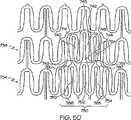
図51〜図52に示すように、代替ステント812および枝部830が示されている。この実施形態において、枝部830は上述の枝部330と形状が類似している。しかし、枝部830は、先端側枝部836が基端側枝部832内に入れ子になった入れ子式ストラット形態からなる変形ストラット構造を有する。具体的に言えば、未拡張位置において、先端側枝部ストラット840,842,844は枝部830の基端側ストラット850,852,854と同調して、基端側ストラット内に入れ子になっている。先端側枝部ストラット840,842,844の長手方向ストラット部845および各湾曲部847は、
各基端側枝部ストラット850,852,854の長手方向ストラット部855および各湾曲部857内に配置されている。外側側方先端側ストラット840,844は、湾曲領域860、862で外側側方基端側ストラット850,854に連結されており、それゆえ、先端側枝部ストラット840,842,844と、基端側枝部ストラット850,853,854との間で単一の接合空間または開口863を画定している。図52で最も良く分るように、開口863は上述の枝部330の開口364より小さい。他の実施形態に関して上述したように、操作時、枝部830は、ステント本体814に関して外側に拡張するように構成されている。枝部830は、完全拡張させると、内側枝管壁の近位側と遠位側とを少なくとも部分的にステント被覆し得る。具体的に言えば、枝部830は湾曲領域864,866で旋回可能であり、その結果、枝部830は、ステント本体814の残りの部分から外側に枝管内に延びた第1位置に位置し、枝管壁の一部を支持する。枝部830は、基端側枝部ストラット850,852,854の反対側の枝管を支持するために、先端側枝部ストラット840,842,844を湾曲領域860,862の周りに内側に旋回させて、先端側枝部ストラット840,842,844を基端側枝部ストラット850,852,854から離すことにより、さらに第2位置に拡張させ得る。この第2拡張位置では、基端側枝部ストラット850,852,854の外面が枝管壁に接触し枝管壁を支持し、先端側枝部ストラット840,842,844の下面が枝管壁に接触し同枝管壁を支持することが分るであろう。ステント812は、ステント312に関して上述したものと同様な方法で搬送可能であり、枝部830は、枝部330と同様な方法で拡張され得る。具体的に言えば、枝部830は、開口863を介して延びる第2カテーテルに先端方向の力を加えて、先端側枝部ストラット840,842,844を基端側枝部ストラット850,852,854に関して移動かつ/または旋回させることにより第1拡張位置から第2拡張位置に移動させ得る。As shown in FIGS. 51-52, an
Each
図53〜図54に示すように、代替ステント912および枝部930が示されている。この実施形態において、枝部930は上述の枝部830と形状が類似している。しかし、枝部930は、外側側方の先端側枝部ストラット940,944が外側側方の基端側枝部ストラットの基端部に隣接する湾曲領域960,962で外側側方お基端側枝部ストラット950,954に連結している変形ストラット構造を有する。この関連で、操作時、枝部930は、枝管壁の一部を支持するために、ステント本体914の残りの部分から外側に枝管内に延びた第1位置になるように、湾曲領域960,962で旋回し得る。枝部930は、先端側枝部ストラット940,942,944を湾曲領域960,962の周りに内側に旋回させ、先端側枝部ストラット940,942,944の基端湾曲領域949,951を先端湾曲部941および945の周りに下向きに旋回させることによりさらに第2位置に拡張され得る。この第2拡張位置において、先端側枝部ストラット940,942,944は、基端側枝部ストラット950,952,954から離間されて配置され、基端側枝部ストラットの反対側の枝管壁を支持する。この第2拡張位置では、基端側枝部ストラット950,952,954の外面が枝管壁に接触し枝管壁を支持し、先端側枝部ストラット940,942,944の下面が枝管壁に接触し同枝管壁を支持することが分るであろう。ステント912は、ステント812に関して上述したものと同様な方法で搬送可能であり、枝部930は、枝部830と同様な方法で拡張させ得る。 As shown in FIGS. 53-54, an
図55〜図56を参照すると、代替ステント1012および枝部1030が示されている。この実施形態では、枝部1030は上述の枝部830と形状が類似している。しかし、先端側枝部は、単一のコネクタ1070によって先端方向に隣接するリング1038に接続されている。コネクタ1070は、先端側枝部ストラット1040,1042,1044の少なくとも1つをリング1038に長手方向に連結している。この実施形態において、コネクタ1070は、リング1038を、先端側枝部ストラット1040,1042,1044の基端湾曲部1049,1051,1053の1つに連結している。操作時、枝部1030は、枝部830とほとんど同じ方法で拡張するが、ただし、コネクタ107
0に隣接する先端側枝部の一部は、第1拡張位置への外側拡張に少なくとも部分的に抵抗し、先端側枝部は、コネクタ1070が先端側枝部ストラットと交わる接合部または個所に関して外側に回転し得る。第2拡張位置において、コネクタ1070は、主管が枝管と交わる体内管壁の入口部または遷移領域の一部に接触しその部分を支持することが好ましい。Referring to FIGS. 55-56, an
A portion of the distal branch adjacent to zero at least partially resists outward expansion to the first expanded position, and the distal branch rotates outward with respect to the junction or location where the
本明細書に記載したステントは該ステント上にコーティングされた1種以上の薬物を含み得る。1つの例示的薬物コーティングが国際出願第WO04/009771号パンフレットに記載されている。上述の枝部30,330,430,530,630,630,830,930,1030を有するステントの1つの特定用途は局所ドラッグデリバリー用である。 The stent described herein can include one or more drugs coated on the stent. One exemplary drug coating is described in International Application No. WO 04/009771. One particular application of a stent having the
1種以上の薬物コーティングは、本発明のステントの主管部の壁内もしくは上、または枝部の壁内もしくは上を含めた、ステントの壁内もしくは壁上の任意の位置に存在し得る。貯留部の位置は、最高濃度の薬剤送達が望まれる部位に依存する。 The one or more drug coatings may be present anywhere in or on the wall of the stent, including in or on the main vessel wall or on the branch wall or on the stent of the present invention. The location of the reservoir depends on the site where the highest concentration of drug delivery is desired.
したがって、貯留槽の長さ、幅および厚さはさまざまであり、所望の薬物分布や、治療すべき主管および枝管のサイズに応じて調整され得る。例えば、狭い管内では流体流れを妨げるほど厚い貯留槽も太い管用には最適な厚さであり得る。 Accordingly, the length, width and thickness of the reservoir will vary and can be adjusted depending on the desired drug distribution and the size of the main and branch to be treated. For example, a reservoir that is thick enough to impede fluid flow in a narrow tube may be the optimum thickness for a thick tube.
本発明のステントは、ステント位置で主管と枝管の両方の壁の細胞に薬物を局所デリバリーするための担体として用い得る。ステント隣接領域の細胞の治療に特に適した薬物としては、抗再狭窄薬および抗血栓薬がある。所望なら、ステント壁のさまざまな領域内または上に配置された貯留槽に、異なる濃度の薬物、または異なる薬物を入れてもよい。例えば、主管細胞を第1の薬物、薬物組み合わせ、および/または薬物濃度で治療し、枝管細胞を第2の異なる薬物、薬物組み合せ、および/または薬物濃度で治療するのも好ましいであろう。別の例として、体内管の分岐部近くで高濃度の高再狭窄薬を維持することも好ましいであろう。さらに別の非限定例として、ステントの3つの開放端部(主部の2端部、枝部の一端部)で高濃度の抗再狭窄薬を維持することも好ましいであろう。本開示を読めば、本発明の精神および範囲内で2つ以上の貯留槽の多くの組み合せが可能であることが当業者には分るであろう。 The stent of the present invention can be used as a carrier for local delivery of drugs to cells in both the main and branch walls at the stent location. Particularly suitable drugs for the treatment of cells adjacent to the stent include anti-restenosis drugs and anti-thrombotic drugs. If desired, different concentrations of drugs or different drugs may be placed in reservoirs located in or on various regions of the stent wall. For example, it may be preferred to treat main duct cells with a first drug, drug combination, and / or drug concentration, and treat branch duct cells with a second different drug, drug combination, and / or drug concentration. As another example, it may be preferable to maintain a high concentration of a high restenosis drug near the bifurcation of the body vessel. As yet another non-limiting example, it may be preferable to maintain a high concentration of anti-restenosis drug at the three open ends of the stent (two ends of the main portion, one end of the branch). After reading this disclosure, those skilled in the art will recognize that many combinations of two or more reservoirs are possible within the spirit and scope of the invention.
本発明はさらに、本発明の1つ以上のステントを含むキットを提供する。本発明のキットは、1つ以上のステントの他に、例えば、1つ以上のデリバリーカテーテル、バルーン、および/または使用説明書を含み得る。本発明のキット中、1つ以上のステントはバルーンまたはカテーテル内または上に搭載し得る。あるいは、1つ以上のステントは、バルーンまたはカテーテルから分離して、使用前にバルーンまたはカテーテル内または上に取り付けてもよい。 The present invention further provides kits comprising one or more stents of the present invention. In addition to one or more stents, the kit of the present invention may include, for example, one or more delivery catheters, balloons, and / or instructions for use. In the kit of the invention, one or more stents may be mounted in or on a balloon or catheter. Alternatively, one or more stents may be separated from the balloon or catheter and mounted in or on the balloon or catheter prior to use.
本発明をその特定の実施形態および実施例に関連して説明したが、本開示を読めば、当業者には多くの代替形態、変形形態および変更形態が容易に分ることは明らかである。したがって、本発明は、添付特許請求の範囲の精神および広範な範囲内に含まれるすべてのそのような代替形態、変形形態および変更形態を包含するものとする。 Although the present invention has been described with reference to specific embodiments and examples thereof, it is evident that many alternatives, modifications and variations will readily occur to those skilled in the art after reading this disclosure. Accordingly, the present invention is intended to embrace all such alternatives, modifications and variations that fall within the spirit and broad scope of the appended claims.
Claims (10)
Translated fromJapanese主ステント本体であって、本体壁を有し、本体壁は、複数のリング部を備え、かつ長手軸線に沿って先端部から基端部まで延びて、先端部と基端部との間に延びる主ルーメンを画定する、主ステント本体と、
枝部であって、本体壁に連結された枝部壁を有し、前記主ステント本体の先端部と基端部との間に配置され、主ステント本体に関して第1位置から第2位置に移動可能な枝部とを備え、
枝部壁は、第1位置では、前記本体壁とほぼ同一平面内に位置し、第2位置では、本体壁に関して偏位され、
ステント枝部は基端側枝部と先端側枝部とを有し、基端側枝部は複数の基端側枝部ストラットを備え、先端側枝部は複数の先端側枝部ストラットを備え、
複数の基端側枝部ストラットはそれぞれ、湾曲部で連結された2つのほぼ平行なストラット部を備え、複数の先端側枝部ストラットの各々は、湾曲部で連結された2つのほぼ平行でないストラット部を備えることを特徴とするステント。In a stent for placement in a branched body lumen having a main branch and a side branch,
A main stent body having a main body wall, the main body wall having a plurality of ring portions and extending from the distal end portion to the proximal end portion along the longitudinal axis, and between the distal end portion and the proximal end portion; A main stent body defining a main lumen extending;
A branch having a branch wall coupled to the body wall, disposed between a distal end and a proximal end of the main stent body and moving from a first position to a second position with respect to the main stent body; With possible branches,
The branch wall is located in substantially the same plane as the main body wall in the first position, and is offset with respect to the main body wall in the second position;
The stent branch has a proximal branch and a distal branch, the proximal branch includes a plurality of proximal branch struts, and the distal branch includes a plurality of distal branch struts,
Each of the plurality of proximal side branch struts includes two substantially parallel struts connected by a curved portion, and each of the plurality of distal side branch struts has two substantially non-parallel struts connected by a curved portion. A stent characterized by comprising.
のストラットに連結され、複数の先端側枝部ストラットの最後のストラットが複数の基端側枝部ストラットの最後のストラットに連結されている請求項1に記載のステント。The first strut of multiple distal branch struts is connected to the first strut of multiple proximal branch struts, and the last strut of multiple distal branch struts is connected to the last strut of multiple proximal branch struts The stent according to claim1 .
主ステント本体であって、長手軸線に沿って先端部から基端部まで延びて、先端部と基端部との間に延びる主ルーメンを画定する本体壁を有する主ステント本体と、
複数のリング部を備える枝部壁を有する枝部とを備え、枝部壁は本体壁に連結されており、該枝部は前記主ステント本体の先端部と基端部との間に配置され、主ステント本体に関して第1位置から第2位置に移動可能であり、
枝部壁は、第1位置では、前記本体壁とほぼ同一平面内に位置し、第2位置では、本体壁に関して偏位され、
複数の先端側枝部ストラットの各々は、基端湾曲部で連結された2つのほぼ平行なストラット部を備え、複数の基端側枝部ストラットはそれぞれ、先端湾曲部で連結された2つのほぼ平行なストラット部を備え、複数の先端側枝管ストラットは先端湾曲部で相互連結され、複数の基端側枝管ストラットは基端湾曲部で相互連結されており、
第1位置において、複数の先端側枝部ストラットが複数の基端側枝部ストラット内に入れ子になっており、
前記入れ子の構造において、複数の先端側枝部ストラットは基端側枝部ストラットから側方に偏位させられており、複数の先端側枝部ストラットの基端湾曲部が基端側枝部ストラットの基端湾曲部に実質的に隣接していることを特徴とするステント。In a stent for placement in a branched body lumen having a main branch and a side branch,
A main stent body having a body wall extending from a distal end to a proximal end along a longitudinal axis and defining a main lumen extending between the distal end and the proximal end;
A branch portion having a branch wall with a plurality of ring portions, the branch wall being connected to the body wall, the branch portion being disposed between the distal end portion and the proximal end portion of the main stent body. Moveable from a first position to a second position with respect to the main stent body;
The branch wall is located in substantially the same plane as the main body wall in the first position, and is offset with respect to the main body wall in the second position;
Each of the plurality of distal side branch struts includes two substantially parallel struts connected by proximal curved portions, and each of the plurality of proximal side branch struts is connected by two substantially parallel struts. A plurality of distal side branch struts are interconnected by a distal curved portion, and a plurality of proximal side branch struts are interconnected by a proximal curved portion;
In the first position, a plurality of distal branch struts are nested within a plurality of proximal branch struts,
In the nested structure, the plurality of distal side branch struts are offset laterally from the proximal side branch struts, and the proximal curved portion of the plurality of distal side branch struts is the proximal curvature of the proximal side branch struts. A stent characterizedby being substantially adjacent to a portion .
Applications Claiming Priority (3)
| Application Number | Priority Date | Filing Date | Title |
|---|---|---|---|
| US57757904P | 2004-06-08 | 2004-06-08 | |
| US60/577,579 | 2004-06-08 | ||
| PCT/US2005/019612WO2005122959A2 (en) | 2004-06-08 | 2005-06-06 | Stent with protruding branch portion for bifurcated vessels |
Publications (2)
| Publication Number | Publication Date |
|---|---|
| JP2008501480A JP2008501480A (en) | 2008-01-24 |
| JP5054524B2true JP5054524B2 (en) | 2012-10-24 |
Family
ID=35510237
Family Applications (1)
| Application Number | Title | Priority Date | Filing Date |
|---|---|---|---|
| JP2007527600AExpired - Fee RelatedJP5054524B2 (en) | 2004-06-08 | 2005-06-06 | Stent with protruding branch for branch pipe |
Country Status (5)
| Country | Link |
|---|---|
| US (3) | US7578841B2 (en) |
| EP (1) | EP1753369B1 (en) |
| JP (1) | JP5054524B2 (en) |
| CA (1) | CA2559540A1 (en) |
| WO (1) | WO2005122959A2 (en) |
Families Citing this family (110)
| Publication number | Priority date | Publication date | Assignee | Title |
|---|---|---|---|---|
| US6599316B2 (en)* | 1996-11-04 | 2003-07-29 | Advanced Stent Technologies, Inc. | Extendible stent apparatus |
| EP1723931B1 (en)* | 1996-11-04 | 2012-01-04 | Advanced Stent Technologies, Inc. | Extendible stent apparatus and method for deploying the same |
| US6325826B1 (en)* | 1998-01-14 | 2001-12-04 | Advanced Stent Technologies, Inc. | Extendible stent apparatus |
| US7341598B2 (en) | 1999-01-13 | 2008-03-11 | Boston Scientific Scimed, Inc. | Stent with protruding branch portion for bifurcated vessels |
| US6835203B1 (en) | 1996-11-04 | 2004-12-28 | Advanced Stent Technologies, Inc. | Extendible stent apparatus |
| US8257425B2 (en)* | 1999-01-13 | 2012-09-04 | Boston Scientific Scimed, Inc. | Stent with protruding branch portion for bifurcated vessels |
| CA2360551C (en)* | 1999-01-27 | 2009-12-22 | Scimed Life Systems, Inc. | Bifurcation stent delivery system |
| WO2001021095A2 (en)* | 1999-09-23 | 2001-03-29 | Advanced Stent Technologies, Inc. | Bifurcation stent system and method |
| US20030097169A1 (en) | 2001-02-26 | 2003-05-22 | Brucker Gregory G. | Bifurcated stent and delivery system |
| US7147661B2 (en) | 2001-12-20 | 2006-12-12 | Boston Scientific Santa Rosa Corp. | Radially expandable stent |
| US20060253480A1 (en)* | 2002-04-06 | 2006-11-09 | Staples Peter E | Collaborative design process for a design team, outside suppliers, and outside manufacturers |
| US7326242B2 (en)* | 2002-11-05 | 2008-02-05 | Boston Scientific Scimed, Inc. | Asymmetric bifurcated crown |
| US8083791B2 (en) | 2003-04-14 | 2011-12-27 | Tryton Medical, Inc. | Method of treating a lumenal bifurcation |
| US7972372B2 (en) | 2003-04-14 | 2011-07-05 | Tryton Medical, Inc. | Kit for treating vascular bifurcations |
| US8109987B2 (en)* | 2003-04-14 | 2012-02-07 | Tryton Medical, Inc. | Method of treating a lumenal bifurcation |
| US7731747B2 (en) | 2003-04-14 | 2010-06-08 | Tryton Medical, Inc. | Vascular bifurcation prosthesis with multiple thin fronds |
| US7758630B2 (en) | 2003-04-14 | 2010-07-20 | Tryton Medical, Inc. | Helical ostium support for treating vascular bifurcations |
| US7717953B2 (en) | 2004-10-13 | 2010-05-18 | Tryton Medical, Inc. | Delivery system for placement of prosthesis at luminal OS |
| US8298280B2 (en)* | 2003-08-21 | 2012-10-30 | Boston Scientific Scimed, Inc. | Stent with protruding branch portion for bifurcated vessels |
| US8007528B2 (en)* | 2004-03-17 | 2011-08-30 | Boston Scientific Scimed, Inc. | Bifurcated stent |
| JP5054524B2 (en) | 2004-06-08 | 2012-10-24 | アドバンスド ステント テクノロジーズ, インコーポレイテッド | Stent with protruding branch for branch pipe |
| US9427340B2 (en)* | 2004-12-14 | 2016-08-30 | Boston Scientific Scimed, Inc. | Stent with protruding branch portion for bifurcated vessels |
| US9101500B2 (en)* | 2005-01-10 | 2015-08-11 | Trireme Medical, Inc. | Stent with self-deployable portion having wings of different lengths |
| CN101102728B (en)* | 2005-01-10 | 2011-06-22 | 曲利姆医疗股份有限公司 | Stand with self-deployable portion |
| FR2881946B1 (en)* | 2005-02-17 | 2008-01-04 | Jacques Seguin | DEVICE FOR THE TREATMENT OF BODILY CONDUIT AT BIFURCATION LEVEL |
| US7922754B2 (en) | 2005-04-18 | 2011-04-12 | Trireme Medical, Inc. | Apparatus and methods for delivering prostheses to luminal bifurcations |
| US8608789B2 (en) | 2005-05-24 | 2013-12-17 | Trireme Medical, Inc. | Delivery system for bifurcation stents |
| US8480728B2 (en)* | 2005-05-26 | 2013-07-09 | Boston Scientific Scimed, Inc. | Stent side branch deployment initiation geometry |
| US20060271161A1 (en)* | 2005-05-26 | 2006-11-30 | Boston Scientific Scimed, Inc. | Selective treatment of stent side branch petals |
| US8317855B2 (en)* | 2005-05-26 | 2012-11-27 | Boston Scientific Scimed, Inc. | Crimpable and expandable side branch cell |
| US20070050016A1 (en)* | 2005-08-29 | 2007-03-01 | Boston Scientific Scimed, Inc. | Stent with expanding side branch geometry |
| US7731741B2 (en)* | 2005-09-08 | 2010-06-08 | Boston Scientific Scimed, Inc. | Inflatable bifurcation stent |
| US8043366B2 (en)* | 2005-09-08 | 2011-10-25 | Boston Scientific Scimed, Inc. | Overlapping stent |
| US8038706B2 (en)* | 2005-09-08 | 2011-10-18 | Boston Scientific Scimed, Inc. | Crown stent assembly |
| US20070112418A1 (en)* | 2005-11-14 | 2007-05-17 | Boston Scientific Scimed, Inc. | Stent with spiral side-branch support designs |
| US8435284B2 (en)* | 2005-12-14 | 2013-05-07 | Boston Scientific Scimed, Inc. | Telescoping bifurcated stent |
| US8343211B2 (en)* | 2005-12-14 | 2013-01-01 | Boston Scientific Scimed, Inc. | Connectors for bifurcated stent |
| US20070142904A1 (en)* | 2005-12-20 | 2007-06-21 | Boston Scientific Scimed, Inc. | Bifurcated stent with multiple locations for side branch access |
| US7540881B2 (en) | 2005-12-22 | 2009-06-02 | Boston Scientific Scimed, Inc. | Bifurcation stent pattern |
| US20070208415A1 (en)* | 2006-03-06 | 2007-09-06 | Kevin Grotheim | Bifurcated stent with controlled drug delivery |
| US20070208411A1 (en)* | 2006-03-06 | 2007-09-06 | Boston Scientific Scimed, Inc. | Bifurcated stent with surface area gradient |
| US7833264B2 (en)* | 2006-03-06 | 2010-11-16 | Boston Scientific Scimed, Inc. | Bifurcated stent |
| US20070208414A1 (en)* | 2006-03-06 | 2007-09-06 | Shawn Sorenson | Tapered strength rings on a bifurcated stent petal |
| US8298278B2 (en)* | 2006-03-07 | 2012-10-30 | Boston Scientific Scimed, Inc. | Bifurcated stent with improvement securement |
| US8257419B2 (en)* | 2006-03-10 | 2012-09-04 | Cordis Corporation | Apparatus for treating a bifurcated region of a conduit |
| US20070225798A1 (en)* | 2006-03-23 | 2007-09-27 | Daniel Gregorich | Side branch stent |
| US8348991B2 (en)* | 2006-03-29 | 2013-01-08 | Boston Scientific Scimed, Inc. | Stent with overlap and high expansion |
| US20070233233A1 (en)* | 2006-03-31 | 2007-10-04 | Boston Scientific Scimed, Inc | Tethered expansion columns for controlled stent expansion |
| US20070260304A1 (en)* | 2006-05-02 | 2007-11-08 | Daniel Gregorich | Bifurcated stent with minimally circumferentially projected side branch |
| US20070270935A1 (en)* | 2006-05-18 | 2007-11-22 | Abbott Laboratories | Dual balloon catheter and deployment of same |
| EP2051673A2 (en) | 2006-06-23 | 2009-04-29 | Boston Scientific Limited | Bifurcated stent with twisted hinges |
| EP2043567B1 (en)* | 2006-06-30 | 2011-07-13 | Boston Scientific Limited | Stent design with variable expansion columns along circumference |
| WO2008024943A1 (en)* | 2006-08-23 | 2008-02-28 | Abbott Laboratories | Catheter system and method for delivering medical devices |
| US8216267B2 (en)* | 2006-09-12 | 2012-07-10 | Boston Scientific Scimed, Inc. | Multilayer balloon for bifurcated stent delivery and methods of making and using the same |
| US7951191B2 (en)* | 2006-10-10 | 2011-05-31 | Boston Scientific Scimed, Inc. | Bifurcated stent with entire circumferential petal |
| US8206429B2 (en) | 2006-11-02 | 2012-06-26 | Boston Scientific Scimed, Inc. | Adjustable bifurcation catheter incorporating electroactive polymer and methods of making and using the same |
| US7842082B2 (en) | 2006-11-16 | 2010-11-30 | Boston Scientific Scimed, Inc. | Bifurcated stent |
| US20080147174A1 (en)* | 2006-12-11 | 2008-06-19 | Trireme Medical, Inc. | Apparatus and method of using markers to position stents in bifurcations |
| FR2911063B1 (en) | 2007-01-09 | 2009-03-20 | Stentys S A S Soc Par Actions | RUPTIBLE BRIDGE STRUCTURE FOR STENT, AND STENT INCLUDING SUCH BRIDGE STRUCTURES. |
| US7959668B2 (en) | 2007-01-16 | 2011-06-14 | Boston Scientific Scimed, Inc. | Bifurcated stent |
| US8118861B2 (en)* | 2007-03-28 | 2012-02-21 | Boston Scientific Scimed, Inc. | Bifurcation stent and balloon assemblies |
| US8647376B2 (en)* | 2007-03-30 | 2014-02-11 | Boston Scientific Scimed, Inc. | Balloon fold design for deployment of bifurcated stent petal architecture |
| US7942661B2 (en)* | 2007-07-18 | 2011-05-17 | Boston Scientific Scimed, Inc. | Bifurcated balloon folding method and apparatus |
| US7959669B2 (en)* | 2007-09-12 | 2011-06-14 | Boston Scientific Scimed, Inc. | Bifurcated stent with open ended side branch support |
| US7833266B2 (en) | 2007-11-28 | 2010-11-16 | Boston Scientific Scimed, Inc. | Bifurcated stent with drug wells for specific ostial, carina, and side branch treatment |
| US8277501B2 (en) | 2007-12-21 | 2012-10-02 | Boston Scientific Scimed, Inc. | Bi-stable bifurcated stent petal geometry |
| US8747456B2 (en)* | 2007-12-31 | 2014-06-10 | Boston Scientific Scimed, Inc. | Bifurcation stent delivery system and methods |
| WO2009105699A1 (en) | 2008-02-22 | 2009-08-27 | Endologix, Inc. | Design and method of placement of a graft or graft system |
| US8333003B2 (en)* | 2008-05-19 | 2012-12-18 | Boston Scientific Scimed, Inc. | Bifurcation stent crimping systems and methods |
| US8932340B2 (en) | 2008-05-29 | 2015-01-13 | Boston Scientific Scimed, Inc. | Bifurcated stent and delivery system |
| US8308793B2 (en) | 2008-06-10 | 2012-11-13 | Boston Scientific Scimed, Inc. | Bifurcation catheter assembly with dynamic side branch lumen |
| US20090326643A1 (en)* | 2008-06-27 | 2009-12-31 | Boston Scientific Scimed, Inc. | Balloon folding apparatus and method |
| EP2520320B1 (en) | 2008-07-01 | 2016-11-02 | Endologix, Inc. | Catheter system |
| US9005274B2 (en)* | 2008-08-04 | 2015-04-14 | Stentys Sas | Method for treating a body lumen |
| US12076258B2 (en) | 2008-09-25 | 2024-09-03 | Advanced Bifurcation Systems Inc. | Selective stent crimping |
| US11298252B2 (en) | 2008-09-25 | 2022-04-12 | Advanced Bifurcation Systems Inc. | Stent alignment during treatment of a bifurcation |
| US8828071B2 (en) | 2008-09-25 | 2014-09-09 | Advanced Bifurcation Systems, Inc. | Methods and systems for ostial stenting of a bifurcation |
| US8821562B2 (en) | 2008-09-25 | 2014-09-02 | Advanced Bifurcation Systems, Inc. | Partially crimped stent |
| JP5635515B2 (en) | 2008-09-25 | 2014-12-03 | アドバンスド バイファケーション システムズ, インコーポレイテッド | Partially crimped stent |
| US12324756B2 (en) | 2008-09-25 | 2025-06-10 | Advanced Bifurcation Systems Inc. | System and methods for treating a bifurcation |
| CN101732114B (en)* | 2008-11-04 | 2014-07-30 | 上海微创医疗器械(集团)有限公司 | Coronary artery stent with medicine carrying grooves |
| KR101810379B1 (en) | 2009-02-02 | 2017-12-20 | 코디스 코포레이션 | Flexible stent design |
| GB2469073A (en)* | 2009-03-31 | 2010-10-06 | Barking Havering And Redbridge | Balloon Assisted Occlusion of Aneurysms |
| US20110054587A1 (en) | 2009-04-28 | 2011-03-03 | Endologix, Inc. | Apparatus and method of placement of a graft or graft system |
| US20100318170A1 (en)* | 2009-06-15 | 2010-12-16 | Richard Newhauser | Proximal catheter flap for managing wire twist |
| EP2266508A1 (en)* | 2009-06-25 | 2010-12-29 | Biotronik VI Patent AG | Stent with improved stent design |
| US8382818B2 (en) | 2009-07-02 | 2013-02-26 | Tryton Medical, Inc. | Ostium support for treating vascular bifurcations |
| US8474120B2 (en)* | 2009-10-09 | 2013-07-02 | W. L. Gore & Associates, Inc. | Bifurcated highly conformable medical device branch access |
| JP5401293B2 (en)* | 2009-12-16 | 2014-01-29 | テルモ株式会社 | Biological organ dilator |
| EP2549951B1 (en) | 2010-03-24 | 2017-05-10 | Advanced Bifurcation Systems, Inc. | Stent alignment during treatment of a bifurcation |
| AU2011232362B2 (en) | 2010-03-24 | 2015-12-10 | Advanced Bifurcation Systems Inc. | System and methods for treating a bifurcation |
| CN103037815B (en) | 2010-03-24 | 2015-05-13 | 高级分支系统股份有限公司 | Method and system for treating furcations by temporarily opening side branches |
| JP5697138B2 (en)* | 2010-09-27 | 2015-04-08 | 株式会社カネカ | Stent delivery catheter system |
| US20120109279A1 (en) | 2010-11-02 | 2012-05-03 | Endologix, Inc. | Apparatus and method of placement of a graft or graft system |
| EP2642946B1 (en) | 2010-11-24 | 2023-08-16 | Poseidon Medical Inc. | Support for treating vascular bifurcations |
| US8915950B2 (en) | 2010-12-06 | 2014-12-23 | Covidien Lp | Vascular remodeling device |
| EP4424283A3 (en) | 2011-02-08 | 2024-12-25 | Advanced Bifurcation Systems Inc. | System and methods for treating a bifurcation with a fully crimped stent |
| WO2012109382A2 (en) | 2011-02-08 | 2012-08-16 | Advanced Bifurcation Systems, Inc. | Multi-stent and multi-balloon apparatus for treating bifurcations and methods of use |
| US8808350B2 (en) | 2011-03-01 | 2014-08-19 | Endologix, Inc. | Catheter system and methods of using same |
| CN103547222B (en)* | 2011-05-11 | 2016-02-10 | 柯惠有限合伙公司 | Vascular remodeling device |
| US8501882B2 (en) | 2011-12-19 | 2013-08-06 | Chevron Phillips Chemical Company Lp | Use of hydrogen and an organozinc compound for polymerization and polymer property control |
| US10500077B2 (en) | 2012-04-26 | 2019-12-10 | Poseidon Medical Inc. | Support for treating vascular bifurcations |
| KR101424201B1 (en)* | 2012-08-14 | 2014-08-13 | 이종훈 | Stent provided with window and graft thereof |
| US9186267B2 (en) | 2012-10-31 | 2015-11-17 | Covidien Lp | Wing bifurcation reconstruction device |
| US20140128901A1 (en)* | 2012-11-05 | 2014-05-08 | Kevin Kang | Implant for aneurysm treatment |
| US10709587B2 (en)* | 2013-11-05 | 2020-07-14 | Hameem Unnabi Changezi | Bifurcated stent and delivery system |
| US9375810B2 (en)* | 2014-01-24 | 2016-06-28 | Q3 Medical Devices Limited | Bidirectional stent and method of use thereof |
| WO2017004265A1 (en) | 2015-06-30 | 2017-01-05 | Endologix, Inc. | Locking assembly for coupling guidewire to delivery system |
| US11559387B2 (en)* | 2017-09-12 | 2023-01-24 | W. L Gore & Associates, Inc. | Substrate with rotatable struts for medical device |
| EP3708129A1 (en)* | 2019-03-15 | 2020-09-16 | Biotronik Ag | Implant |
Family Cites Families (370)
| Publication number | Priority date | Publication date | Assignee | Title |
|---|---|---|---|---|
| US4309994A (en) | 1980-02-25 | 1982-01-12 | Grunwald Ronald P | Cardiovascular cannula |
| US4774949A (en) | 1983-06-14 | 1988-10-04 | Fogarty Thomas J | Deflector guiding catheter |
| DE3689650T2 (en)* | 1985-12-17 | 1994-05-26 | United States Surgical Corp | High molecular weight bioabsorbable polymers and implants thereof. |
| IT1202558B (en) | 1987-02-17 | 1989-02-09 | Alberto Arpesani | INTERNAL PROSTHESIS FOR THE REPLACEMENT OF A PART OF THE HUMAN BODY PARTICULARLY IN THE VASCULAR OPERATIONS |
| DE8717643U1 (en) | 1987-05-12 | 1989-09-21 | Domschke, Wolfram, Prof. Dr.med., 8520 Erlangen | Device for endoscopic-transpapillary probing of a bile duct system |
| US4935190A (en)* | 1987-07-10 | 1990-06-19 | William G. Whitney | Method of making balloon retention catheter |
| US4769005A (en) | 1987-08-06 | 1988-09-06 | Robert Ginsburg | Selective catheter guide |
| US4896670A (en) | 1988-04-19 | 1990-01-30 | C. R. Bard, Inc. | Kissing balloon catheter |
| US4906244A (en)* | 1988-10-04 | 1990-03-06 | Cordis Corporation | Balloons for medical devices and fabrication thereof |
| US5087246A (en)* | 1988-12-29 | 1992-02-11 | C. R. Bard, Inc. | Dilation catheter with fluted balloon |
| US5147302A (en)* | 1989-04-21 | 1992-09-15 | Scimed Life Systems, Inc. | Method of shaping a balloon of a balloon catheter |
| WO1990013332A1 (en) | 1989-05-11 | 1990-11-15 | Cedars-Sinai Medical Center | Stent with sustained drug delivery |
| US4994071A (en) | 1989-05-22 | 1991-02-19 | Cordis Corporation | Bifurcating stent apparatus and method |
| US5037392A (en)* | 1989-06-06 | 1991-08-06 | Cordis Corporation | Stent-implanting balloon assembly |
| US5318587A (en)* | 1989-08-25 | 1994-06-07 | C. R. Bard, Inc. | Pleated balloon dilatation catheter and method of use |
| US5147385A (en) | 1989-11-01 | 1992-09-15 | Schneider (Europe) A.G. | Stent and catheter for the introduction of the stent |
| US5053007A (en)* | 1989-12-14 | 1991-10-01 | Scimed Life Systems, Inc. | Compression balloon protector for a balloon dilatation catheter and method of use thereof |
| CA2049973C (en) | 1990-02-28 | 2002-12-24 | Rodney G. Wolff | Intralumenal drug eluting prosthesis |
| US5320634A (en) | 1990-07-03 | 1994-06-14 | Interventional Technologies, Inc. | Balloon catheter with seated cutting edges |
| US5163989A (en)* | 1990-08-27 | 1992-11-17 | Advanced Cardiovascular Systems, Inc. | Method for forming a balloon mold and the use of such mold |
| AR246020A1 (en) | 1990-10-03 | 1994-03-30 | Hector Daniel Barone Juan Carl | A ball device for implanting an intraluminous aortic prosthesis, for repairing aneurysms. |
| ATE121303T1 (en) | 1990-10-04 | 1995-05-15 | Schneider Europ Ag | BALLOON DILATION CATHETER. |
| CA2094597C (en)* | 1990-11-09 | 2003-12-16 | Ronald Sahatjian | Balloon for medical catheter |
| US5112900A (en)* | 1990-11-28 | 1992-05-12 | Tactyl Technologies, Inc. | Elastomeric triblock copolymer compositions and articles made therewith |
| US5628783A (en) | 1991-04-11 | 1997-05-13 | Endovascular Technologies, Inc. | Bifurcated multicapsule intraluminal grafting system and method |
| US5304220A (en) | 1991-07-03 | 1994-04-19 | Maginot Thomas J | Method and apparatus for implanting a graft prosthesis in the body of a patient |
| FR2678508B1 (en) | 1991-07-04 | 1998-01-30 | Celsa Lg | DEVICE FOR REINFORCING VESSELS OF THE HUMAN BODY. |
| JP3619527B2 (en)* | 1991-10-16 | 2005-02-09 | オリンパス株式会社 | In-vivo indwelling tube |
| US5387235A (en) | 1991-10-25 | 1995-02-07 | Cook Incorporated | Expandable transluminal graft prosthesis for repair of aneurysm |
| US5693084A (en) | 1991-10-25 | 1997-12-02 | Cook Incorporated | Expandable transluminal graft prosthesis for repair of aneurysm |
| US5226887A (en)* | 1992-02-07 | 1993-07-13 | Interventional Technologies, Inc. | Collapsible folding angioplasty balloon |
| US5209799A (en)* | 1992-04-17 | 1993-05-11 | Inverventional Technologies, Inc. | Method for manufacturing a folding balloon catheter |
| US5342387A (en) | 1992-06-18 | 1994-08-30 | American Biomed, Inc. | Artificial support for a blood vessel |
| US5447497A (en)* | 1992-08-06 | 1995-09-05 | Scimed Life Systems, Inc | Balloon catheter having nonlinear compliance curve and method of using |
| US5348538A (en)* | 1992-09-29 | 1994-09-20 | Scimed Life Systems, Inc. | Shrinking balloon catheter having nonlinear or hybrid compliance curve |
| US5487730A (en)* | 1992-12-30 | 1996-01-30 | Medtronic, Inc. | Balloon catheter with balloon surface retention means |
| US5523092A (en)* | 1993-04-14 | 1996-06-04 | Emory University | Device for local drug delivery and methods for using the same |
| US5464650A (en) | 1993-04-26 | 1995-11-07 | Medtronic, Inc. | Intravascular stent and method |
| US5824048A (en) | 1993-04-26 | 1998-10-20 | Medtronic, Inc. | Method for delivering a therapeutic substance to a body lumen |
| IL106738A (en) | 1993-08-19 | 1998-02-08 | Mind E M S G Ltd | Device for external correction of deficient valves in venous junctions |
| US5746745A (en)* | 1993-08-23 | 1998-05-05 | Boston Scientific Corporation | Balloon catheter |
| JP3507901B2 (en)* | 1993-10-21 | 2004-03-15 | コンデア・ビスタ・カンパニー | Alumina thickened latex formulation |
| US5632772A (en) | 1993-10-21 | 1997-05-27 | Corvita Corporation | Expandable supportive branched endoluminal grafts |
| US5639278A (en) | 1993-10-21 | 1997-06-17 | Corvita Corporation | Expandable supportive bifurcated endoluminal grafts |
| US5350361A (en)* | 1993-11-10 | 1994-09-27 | Medtronic, Inc. | Tri-fold balloon for dilatation catheter and related method |
| US5607444A (en) | 1993-12-02 | 1997-03-04 | Advanced Cardiovascular Systems, Inc. | Ostial stent for bifurcations |
| US5609627A (en) | 1994-02-09 | 1997-03-11 | Boston Scientific Technology, Inc. | Method for delivering a bifurcated endoluminal prosthesis |
| US6406457B1 (en) | 1994-03-02 | 2002-06-18 | Scimed Life Systems, Inc. | Block copolymer elastomer catheter balloons |
| US6171278B1 (en)* | 1994-03-02 | 2001-01-09 | Scimed Life Systems, Inc. | Block copolymer elastomer catheter balloons |
| US5951941A (en)* | 1994-03-02 | 1999-09-14 | Scimed Life Systems, Inc. | Block copolymer elastomer catheter balloons |
| US5830182A (en)* | 1994-03-02 | 1998-11-03 | Scimed Life Systems, Inc. | Block copolymer elastomer catheter balloons |
| US6146356A (en) | 1994-03-02 | 2000-11-14 | Scimed Life Systems, Inc. | Block copolymer elastomer catheter balloons |
| ES2141928T5 (en)* | 1994-03-02 | 2009-04-16 | Boston Scientific Limited | BALLS OF ELASTOMERO COPOLIMERO IN BLOCKS FOR CATHETER. |
| US5733303A (en)* | 1994-03-17 | 1998-03-31 | Medinol Ltd. | Flexible expandable stent |
| US5456666A (en)* | 1994-04-26 | 1995-10-10 | Boston Scientific Corp | Medical balloon folding into predetermined shapes and method |
| US5810767A (en)* | 1994-05-11 | 1998-09-22 | Localmed, Inc. | Method and apparatus for pressurized intraluminal drug delivery |
| US5683451A (en) | 1994-06-08 | 1997-11-04 | Cardiovascular Concepts, Inc. | Apparatus and methods for deployment release of intraluminal prostheses |
| US5458572A (en)* | 1994-07-01 | 1995-10-17 | Boston Scientific Corp. | Catheter with balloon folding into predetermined configurations and method of manufacture |
| US5636641A (en)* | 1994-07-25 | 1997-06-10 | Advanced Cardiovascular Systems, Inc. | High strength member for intracorporeal use |
| US5609605A (en) | 1994-08-25 | 1997-03-11 | Ethicon, Inc. | Combination arterial stent |
| US5891108A (en)* | 1994-09-12 | 1999-04-06 | Cordis Corporation | Drug delivery stent |
| CA2175720C (en) | 1996-05-03 | 2011-11-29 | Ian M. Penn | Bifurcated stent and method for the manufacture and delivery of same |
| CA2134997C (en) | 1994-11-03 | 2009-06-02 | Ian M. Penn | Stent |
| US5613980A (en) | 1994-12-22 | 1997-03-25 | Chauhan; Tusharsindhu C. | Bifurcated catheter system and method |
| NL9500094A (en) | 1995-01-19 | 1996-09-02 | Industrial Res Bv | Y-shaped stent and method of deployment. |
| US6231600B1 (en)* | 1995-02-22 | 2001-05-15 | Scimed Life Systems, Inc. | Stents with hybrid coating for medical devices |
| US7204848B1 (en) | 1995-03-01 | 2007-04-17 | Boston Scientific Scimed, Inc. | Longitudinally flexible expandable stent |
| DE69622231T2 (en) | 1995-03-01 | 2002-12-05 | Scimed Life Systems, Inc. | LENGTHFLEXIBLE AND EXPANDABLE STENT |
| US20070073384A1 (en) | 1995-03-01 | 2007-03-29 | Boston Scientific Scimed, Inc. | Longitudinally flexible expandable stent |
| US5549552A (en)* | 1995-03-02 | 1996-08-27 | Scimed Life Systems, Inc. | Balloon dilation catheter with improved pushability, trackability and crossability |
| EP0813397A4 (en)* | 1995-03-10 | 1999-10-06 | Cardiovascular Concepts Inc | Tubular endoluminar prosthesis having oblique ends |
| US5709713A (en) | 1995-03-31 | 1998-01-20 | Cardiovascular Concepts, Inc. | Radially expansible vascular prosthesis having reversible and other locking structures |
| US6099562A (en) | 1996-06-13 | 2000-08-08 | Schneider (Usa) Inc. | Drug coating with topcoat |
| US20020091433A1 (en) | 1995-04-19 | 2002-07-11 | Ni Ding | Drug release coated stent |
| FR2733682B1 (en) | 1995-05-04 | 1997-10-31 | Dibie Alain | ENDOPROSTHESIS FOR THE TREATMENT OF STENOSIS ON BIFURCATIONS OF BLOOD VESSELS AND LAYING EQUIPMENT THEREFOR |
| US5591228A (en) | 1995-05-09 | 1997-01-07 | Edoga; John K. | Methods for treating abdominal aortic aneurysms |
| US5833657A (en)* | 1995-05-30 | 1998-11-10 | Ethicon, Inc. | Single-walled balloon catheter with non-linear compliance characteristic |
| US5707348A (en)* | 1995-06-06 | 1998-01-13 | Krogh; Steve S. | Intravenous bandage |
| US6280413B1 (en) | 1995-06-07 | 2001-08-28 | Medtronic Ave, Inc. | Thrombolytic filtration and drug delivery catheter with a self-expanding portion |
| US5609629A (en)* | 1995-06-07 | 1997-03-11 | Med Institute, Inc. | Coated implantable medical device |
| US6033434A (en) | 1995-06-08 | 2000-03-07 | Ave Galway Limited | Bifurcated endovascular stent and methods for forming and placing |
| FR2737969B1 (en) | 1995-08-24 | 1998-01-30 | Rieu Regis | INTRALUMINAL ENDOPROSTHESIS IN PARTICULAR FOR ANGIOPLASTY |
| US5824036A (en) | 1995-09-29 | 1998-10-20 | Datascope Corp | Stent for intraluminal grafts and device and methods for delivering and assembling same |
| US5669924A (en) | 1995-10-26 | 1997-09-23 | Shaknovich; Alexander | Y-shuttle stent assembly for bifurcating vessels and method of using the same |
| FR2740346A1 (en) | 1995-10-30 | 1997-04-30 | Debiotech Sa | ANGIOPLASTY DEVICE FOR ARTERIAL BIFURCATION |
| US5632762A (en) | 1995-11-09 | 1997-05-27 | Hemodynamics, Inc. | Ostial stent balloon |
| US5824040A (en) | 1995-12-01 | 1998-10-20 | Medtronic, Inc. | Endoluminal prostheses and therapies for highly variable body lumens |
| US5882334A (en)* | 1995-12-04 | 1999-03-16 | Target Therapeutics, Inc. | Balloon/delivery catheter assembly with adjustable balloon positioning |
| AUPN775296A0 (en) | 1996-01-25 | 1996-02-22 | Endogad Research Pty Limited | Directional catheter |
| US6017363A (en) | 1997-09-22 | 2000-01-25 | Cordis Corporation | Bifurcated axially flexible stent |
| US6436104B2 (en) | 1996-01-26 | 2002-08-20 | Cordis Corporation | Bifurcated axially flexible stent |
| US6258116B1 (en) | 1996-01-26 | 2001-07-10 | Cordis Corporation | Bifurcated axially flexible stent |
| US6796997B1 (en)* | 1996-03-05 | 2004-09-28 | Evysio Medical Devices Ulc | Expandable stent |
| US6124007A (en) | 1996-03-06 | 2000-09-26 | Scimed Life Systems Inc | Laminate catheter balloons with additive burst strength and methods for preparation of same |
| US6071285A (en) | 1996-03-25 | 2000-06-06 | Lashinski; Robert D. | Rapid exchange folded balloon catheter and stent delivery system |
| US5824042A (en) | 1996-04-05 | 1998-10-20 | Medtronic, Inc. | Endoluminal prostheses having position indicating markers |
| BE1010183A3 (en) | 1996-04-25 | 1998-02-03 | Dereume Jean Pierre Georges Em | Luminal endoprosthesis FOR BRANCHING CHANNELS OF A HUMAN OR ANIMAL BODY AND MANUFACTURING METHOD THEREOF. |
| US5922021A (en)* | 1996-04-26 | 1999-07-13 | Jang; G. David | Intravascular stent |
| US6783543B2 (en) | 2000-06-05 | 2004-08-31 | Scimed Life Systems, Inc. | Intravascular stent with increasing coating retaining capacity |
| US6251133B1 (en) | 1996-05-03 | 2001-06-26 | Medinol Ltd. | Bifurcated stent with improved side branch aperture and method of making same |
| UA58485C2 (en) | 1996-05-03 | 2003-08-15 | Медінол Лтд. | Method for manufacture of bifurcated stent (variants) and bifurcated stent (variants) |
| US6770092B2 (en) | 1996-05-03 | 2004-08-03 | Medinol Ltd. | Method of delivering a bifurcated stent |
| US6440165B1 (en) | 1996-05-03 | 2002-08-27 | Medinol, Ltd. | Bifurcated stent with improved side branch aperture and method of making same |
| US5851464A (en) | 1996-05-13 | 1998-12-22 | Cordis Corporation | Method of making a fuseless soft tip catheter |
| US5718684A (en)* | 1996-05-24 | 1998-02-17 | Gupta; Mukesh | Multi-lobed balloon catheter |
| US5669932A (en) | 1996-05-29 | 1997-09-23 | Isostent, Inc. | Means for accurately positioning an expandable stent |
| US5617878A (en) | 1996-05-31 | 1997-04-08 | Taheri; Syde A. | Stent and method for treatment of aortic occlusive disease |
| AU2785597A (en) | 1996-05-31 | 1998-01-05 | Bard Galway Limited | Bifurcated endovascular stents and method and apparatus for their placement |
| US5755773A (en) | 1996-06-04 | 1998-05-26 | Medtronic, Inc. | Endoluminal prosthetic bifurcation shunt |
| FR2749500B1 (en) | 1996-06-06 | 1998-11-20 | Jacques Seguin | DEVICE ALLOWING THE TREATMENT OF BODY DUCTS AT THE LEVEL OF A BIFURCATION |
| US8728143B2 (en) | 1996-06-06 | 2014-05-20 | Biosensors International Group, Ltd. | Endoprosthesis deployment system for treating vascular bifurcations |
| US7238197B2 (en)* | 2000-05-30 | 2007-07-03 | Devax, Inc. | Endoprosthesis deployment system for treating vascular bifurcations |
| US5697971A (en) | 1996-06-11 | 1997-12-16 | Fischell; Robert E. | Multi-cell stent with cells having differing characteristics |
| US5676697A (en) | 1996-07-29 | 1997-10-14 | Cardiovascular Dynamics, Inc. | Two-piece, bifurcated intraluminal graft for repair of aneurysm |
| US5922020A (en)* | 1996-08-02 | 1999-07-13 | Localmed, Inc. | Tubular prosthesis having improved expansion and imaging characteristics |
| US5749825A (en) | 1996-09-18 | 1998-05-12 | Isostent, Inc. | Means method for treatment of stenosed arterial bifurcations |
| US5755778A (en) | 1996-10-16 | 1998-05-26 | Nitinol Medical Technologies, Inc. | Anastomosis device |
| US7341598B2 (en) | 1999-01-13 | 2008-03-11 | Boston Scientific Scimed, Inc. | Stent with protruding branch portion for bifurcated vessels |
| US6325826B1 (en) | 1998-01-14 | 2001-12-04 | Advanced Stent Technologies, Inc. | Extendible stent apparatus |
| EP1723931B1 (en) | 1996-11-04 | 2012-01-04 | Advanced Stent Technologies, Inc. | Extendible stent apparatus and method for deploying the same |
| US7591846B2 (en) | 1996-11-04 | 2009-09-22 | Boston Scientific Scimed, Inc. | Methods for deploying stents in bifurcations |
| US6596020B2 (en) | 1996-11-04 | 2003-07-22 | Advanced Stent Technologies, Inc. | Method of delivering a stent with a side opening |
| US6599316B2 (en) | 1996-11-04 | 2003-07-29 | Advanced Stent Technologies, Inc. | Extendible stent apparatus |
| US6692483B2 (en) | 1996-11-04 | 2004-02-17 | Advanced Stent Technologies, Inc. | Catheter with attached flexible side sheath |
| US6835203B1 (en) | 1996-11-04 | 2004-12-28 | Advanced Stent Technologies, Inc. | Extendible stent apparatus |
| US7220275B2 (en) | 1996-11-04 | 2007-05-22 | Advanced Stent Technologies, Inc. | Stent with protruding branch portion for bifurcated vessels |
| US5972017A (en) | 1997-04-23 | 1999-10-26 | Vascular Science Inc. | Method of installing tubular medical graft connectors |
| US6261320B1 (en) | 1996-11-21 | 2001-07-17 | Radiance Medical Systems, Inc. | Radioactive vascular liner |
| FR2756173B1 (en) | 1996-11-22 | 1999-02-12 | Marcade Jean Paul | MODULAR AND EXPANDABLE ENDOPROSTHESIS FOR THE ARTERIAL NETWORK |
| ZA9710342B (en) | 1996-11-25 | 1998-06-10 | Alza Corp | Directional drug delivery stent and method of use. |
| US5749890A (en) | 1996-12-03 | 1998-05-12 | Shaknovich; Alexander | Method and system for stent placement in ostial lesions |
| IT1289815B1 (en) | 1996-12-30 | 1998-10-16 | Sorin Biomedica Cardio Spa | ANGIOPLASTIC STENT AND RELATED PRODUCTION PROCESS |
| DE29701758U1 (en) | 1997-02-01 | 1997-03-27 | Jomed Implantate GmbH, 72414 Rangendingen | Radially expandable stent for implantation in a body vessel, particularly in the area of a vascular branch |
| DE29701883U1 (en) | 1997-02-04 | 1997-03-27 | Beck, Harry, 71732 Tamm | Central lubrication |
| US5720735A (en) | 1997-02-12 | 1998-02-24 | Dorros; Gerald | Bifurcated endovascular catheter |
| AU6665798A (en) | 1997-02-25 | 1998-09-09 | Scimed Life Systems, Inc. | Stents and stent delivery and dilatation system for bifurcation lesions |
| US6096073A (en) | 1997-02-25 | 2000-08-01 | Scimed Life Systems, Inc. | Method of deploying a stent at a lesion site located at a bifurcation in a parent vessel |
| GB9703859D0 (en) | 1997-02-25 | 1997-04-16 | Plante Sylvain | Expandable intravascular stent |
| US20020133222A1 (en)* | 1997-03-05 | 2002-09-19 | Das Gladwin S. | Expandable stent having a plurality of interconnected expansion modules |
| US5843172A (en)* | 1997-04-15 | 1998-12-01 | Advanced Cardiovascular Systems, Inc. | Porous medicated stent |
| US6240616B1 (en) | 1997-04-15 | 2001-06-05 | Advanced Cardiovascular Systems, Inc. | Method of manufacturing a medicated porous metal prosthesis |
| US6273913B1 (en) | 1997-04-18 | 2001-08-14 | Cordis Corporation | Modified stent useful for delivery of drugs along stent strut |
| EP1011532B1 (en) | 1997-04-23 | 2014-05-07 | Ethicon Endo-Surgery, Inc. | Bifurcated stent and distal protection system |
| US6033433A (en)* | 1997-04-25 | 2000-03-07 | Scimed Life Systems, Inc. | Stent configurations including spirals |
| US6013054A (en) | 1997-04-28 | 2000-01-11 | Advanced Cardiovascular Systems, Inc. | Multifurcated balloon catheter |
| ATE336958T1 (en) | 1997-05-07 | 2006-09-15 | Cordis Corp | INTRAVASCULAR STENT AND SYSTEM FOR INSERTING (OBSTRUCTION OF THE OSTIUM OF A VESSEL) |
| DE29708803U1 (en) | 1997-05-17 | 1997-07-31 | Jomed Implantate GmbH, 72414 Rangendingen | Radially expandable stent for implantation in a body vessel in the area of a vascular branch |
| US5906641A (en) | 1997-05-27 | 1999-05-25 | Schneider (Usa) Inc | Bifurcated stent graft |
| CA2424551A1 (en) | 1997-05-27 | 1998-11-27 | Schneider (Usa) Inc. | Stent and stent-graft for treating branched vessels |
| EP0891751A1 (en) | 1997-07-18 | 1999-01-20 | Thomas Prof. Dr. Ischinger | Vascular stent for bifurcations, sidebranches and ostial lesions and an application catheter and method for implantation |
| IT1294216B1 (en) | 1997-07-28 | 1999-03-24 | Marco Zimarino | ENDOVASCULAR PROSTHESIS IN PARTICULAR FOR ANGIOPLASTIC INTERVENTIONS |
| IT1293690B1 (en) | 1997-08-08 | 1999-03-08 | Sorin Biomedica Cardio Spa | ANGIOPLASTIC STENT, PARTICULARLY FOR THE TREATMENT OF AORTO-HOSPITAL AND HOSPITAL INJURIES. |
| US6165195A (en) | 1997-08-13 | 2000-12-26 | Advanced Cardiovascylar Systems, Inc. | Stent and catheter assembly and method for treating bifurcations |
| US6361544B1 (en) | 1997-08-13 | 2002-03-26 | Advanced Cardiovascular Systems, Inc. | Stent and catheter assembly and method for treating bifurcations |
| AU747698B2 (en) | 1997-09-23 | 2002-05-16 | Design & Performance - Cyprus Limited | Bifurcated stent with flexible side portion |
| US6520988B1 (en) | 1997-09-24 | 2003-02-18 | Medtronic Ave, Inc. | Endolumenal prosthesis and method of use in bifurcation regions of body lumens |
| JP4292710B2 (en) | 1997-09-24 | 2009-07-08 | エム イー ディ インスチィチュート インク | Radially expandable stent |
| US6086611A (en) | 1997-09-25 | 2000-07-11 | Ave Connaught | Bifurcated stent |
| US5972027A (en) | 1997-09-30 | 1999-10-26 | Scimed Life Systems, Inc | Porous stent drug delivery system |
| US5928193A (en) | 1997-10-03 | 1999-07-27 | Boston Scientific Corporation | Balloon catheterization |
| US6013091A (en)* | 1997-10-09 | 2000-01-11 | Scimed Life Systems, Inc. | Stent configurations |
| US5893887A (en) | 1997-10-14 | 1999-04-13 | Iowa-India Investments Company Limited | Stent for positioning at junction of bifurcated blood vessel and method of making |
| US6273908B1 (en) | 1997-10-24 | 2001-08-14 | Robert Ndondo-Lay | Stents |
| US6033435A (en) | 1997-11-03 | 2000-03-07 | Divysio Solutions Ulc | Bifurcated stent and method for the manufacture and delivery of same |
| JP4172912B2 (en) | 1997-11-07 | 2008-10-29 | エクスパンダブル・グラフツ・パートナーシツプ | Intravascular stent and method for manufacturing the intravascular stent |
| EP0951310B1 (en) | 1997-11-07 | 2005-05-18 | Ave Connaught | Balloon catheter for repairing bifurcated vessels |
| US6013055A (en)* | 1997-11-13 | 2000-01-11 | Boston Scientific Corporation | Catheter balloon having selected folding characteristics |
| US6030414A (en) | 1997-11-13 | 2000-02-29 | Taheri; Syde A. | Variable stent and method for treatment of arterial disease |
| US5961548A (en) | 1997-11-18 | 1999-10-05 | Shmulewitz; Ascher | Bifurcated two-part graft and methods of implantation |
| US6129754A (en) | 1997-12-11 | 2000-10-10 | Uni-Cath Inc. | Stent for vessel with branch |
| AU2078599A (en) | 1998-01-08 | 1999-07-26 | Mark Wilson Ian Webster | Self-expanding bifurcation stent and delivery system |
| WO1999036015A1 (en) | 1998-01-16 | 1999-07-22 | Emory University | Catheter and method of ostial stent placement |
| CA2220864A1 (en) | 1998-01-20 | 1999-07-20 | Nisar Huq | A bifurcation stent |
| US6395018B1 (en) | 1998-02-09 | 2002-05-28 | Wilfrido R. Castaneda | Endovascular graft and process for bridging a defect in a main vessel near one of more branch vessels |
| DE69929036T2 (en) | 1998-02-12 | 2006-08-31 | Thomas R. North Vancouver Marotta | ENDOVASCULAR PROSTHESIS |
| US6033380A (en)* | 1998-02-13 | 2000-03-07 | Cordis Corporation | Six-pleated catheter balloon and device for forming same |
| AU2684499A (en) | 1998-02-17 | 1999-08-30 | G. David Jang | Tubular stent consists of chevron-shape expansion struts and ipsilaterally attached m-frame connectors |
| US5938697A (en) | 1998-03-04 | 1999-08-17 | Scimed Life Systems, Inc. | Stent having variable properties |
| US6113579A (en) | 1998-03-04 | 2000-09-05 | Scimed Life Systems, Inc. | Catheter tip designs and methods for improved stent crossing |
| US6099497A (en) | 1998-03-05 | 2000-08-08 | Scimed Life Systems, Inc. | Dilatation and stent delivery system for bifurcation lesions |
| US6132461A (en) | 1998-03-27 | 2000-10-17 | Intratherapeutics, Inc. | Stent with dual support structure |
| US7208010B2 (en) | 2000-10-16 | 2007-04-24 | Conor Medsystems, Inc. | Expandable medical device for delivery of beneficial agent |
| US7179289B2 (en) | 1998-03-30 | 2007-02-20 | Conor Medsystems, Inc. | Expandable medical device for delivery of beneficial agent |
| US7208011B2 (en) | 2001-08-20 | 2007-04-24 | Conor Medsystems, Inc. | Implantable medical device with drug filled holes |
| US6241762B1 (en) | 1998-03-30 | 2001-06-05 | Conor Medsystems, Inc. | Expandable medical device with ductile hinges |
| US6149957A (en) | 1998-04-09 | 2000-11-21 | Nestec S.A. | Aroma recovery process |
| US6206916B1 (en) | 1998-04-15 | 2001-03-27 | Joseph G. Furst | Coated intraluminal graft |
| US6093203A (en) | 1998-05-13 | 2000-07-25 | Uflacker; Renan | Stent or graft support structure for treating bifurcated vessels having different diameter portions and methods of use and implantation |
| US6129757A (en) | 1998-05-18 | 2000-10-10 | Scimed Life Systems | Implantable members for receiving therapeutically useful compositions |
| US6168621B1 (en) | 1998-05-29 | 2001-01-02 | Scimed Life Systems, Inc. | Balloon expandable stent with a self-expanding portion |
| DE69933560T2 (en) | 1998-06-19 | 2007-08-30 | Endologix, Inc., Irvine | SELF-EXPANDING, CRUSHING, ENOVOVASCULAR PROSTHESIS |
| US6129738A (en) | 1998-06-20 | 2000-10-10 | Medtronic Ave, Inc. | Method and apparatus for treating stenoses at bifurcated regions |
| US6261319B1 (en) | 1998-07-08 | 2001-07-17 | Scimed Life Systems, Inc. | Stent |
| US6264662B1 (en) | 1998-07-21 | 2001-07-24 | Sulzer Vascutek Ltd. | Insertion aid for a bifurcated prosthesis |
| US20020038146A1 (en) | 1998-07-29 | 2002-03-28 | Ulf Harry | Expandable stent with relief cuts for carrying medicines and other materials |
| WO2000007523A1 (en) | 1998-07-31 | 2000-02-17 | Novo Rps Ulc | Bifurcated stent delivery system and method of use |
| US6143002A (en) | 1998-08-04 | 2000-11-07 | Scimed Life Systems, Inc. | System for delivering stents to bifurcation lesions |
| EP1105169A1 (en) | 1998-08-20 | 2001-06-13 | Cook Incorporated | Coated implantable medical device |
| US6117117A (en) | 1998-08-24 | 2000-09-12 | Advanced Cardiovascular Systems, Inc. | Bifurcated catheter assembly |
| US6126652A (en) | 1998-09-08 | 2000-10-03 | Medtronic Inc. | Catheter balloon refolding tool and method of use |
| ATE347333T1 (en) | 1998-09-21 | 2006-12-15 | Metz Katharina | PROSTHESIS HOSE CONNECTION |
| US6206915B1 (en) | 1998-09-29 | 2001-03-27 | Medtronic Ave, Inc. | Drug storing and metering stent |
| US6017324A (en) | 1998-10-20 | 2000-01-25 | Tu; Lily Chen | Dilatation catheter having a bifurcated balloon |
| US6293967B1 (en) | 1998-10-29 | 2001-09-25 | Conor Medsystems, Inc. | Expandable medical device with ductile hinges |
| DE19855421C2 (en) | 1998-11-02 | 2001-09-20 | Alcove Surfaces Gmbh | Implant |
| WO2000027307A1 (en) | 1998-11-08 | 2000-05-18 | Brainwave Cardio-Vascular Technologies Ltd. | The sheet expandable trousers stent and device for its implantation |
| WO2000027463A1 (en) | 1998-11-11 | 2000-05-18 | Mark Wilson Ian Webster | Bifurcation stent and delivery systems |
| EP1047357A1 (en) | 1998-11-12 | 2000-11-02 | Advanced Cardiovascular Systems, Inc. | Stent having non-uniform structure |
| WO2000033769A1 (en) | 1998-12-11 | 2000-06-15 | Endologix, Inc. | Endoluminal vascular prosthesis |
| US6059824A (en) | 1998-12-23 | 2000-05-09 | Taheri; Syde A. | Mated main and collateral stent and method for treatment of arterial disease |
| US20050060027A1 (en) | 1999-01-13 | 2005-03-17 | Advanced Stent Technologies, Inc. | Catheter balloon systems and methods |
| US7655030B2 (en) | 2003-07-18 | 2010-02-02 | Boston Scientific Scimed, Inc. | Catheter balloon systems and methods |
| CA2360587A1 (en) | 1999-01-15 | 2000-07-20 | Darin C. Gittings | Methods and devices for forming vascular anastomoses |
| CA2360551C (en) | 1999-01-27 | 2009-12-22 | Scimed Life Systems, Inc. | Bifurcation stent delivery system |
| CA2360168C (en) | 1999-02-01 | 2008-10-14 | Hideki Hyodoh | Woven bifurcated and trifurcated stents and methods for making the same |
| AU2529600A (en) | 1999-02-12 | 2000-08-29 | Novo Rps Ulc | Endovascular prosthesis |
| US6110201A (en) | 1999-02-18 | 2000-08-29 | Venpro | Bifurcated biological pulmonary valved conduit |
| IT1305301B1 (en) | 1999-02-24 | 2001-05-04 | Mariano Gargiulo | FITTING FOR VASCULAR ANASTOMOSIS. |
| IT1309583B1 (en) | 1999-02-26 | 2002-01-24 | Ams Italia S R L | PERFECTED CATHETER FOR VASCULAR INTERVENTIONS. |
| AU2637499A (en) | 1999-02-28 | 2000-09-21 | Brainwave Cardio-Vascular Technologies Ltd. | A modular bifurcated intraluminal stent |
| US6261316B1 (en) | 1999-03-11 | 2001-07-17 | Endologix, Inc. | Single puncture bifurcation graft deployment system |
| US6558422B1 (en) | 1999-03-26 | 2003-05-06 | University Of Washington | Structures having coated indentations |
| EP1164968A1 (en) | 1999-03-30 | 2002-01-02 | Angiolink Corporation | Angular vascular stent |
| US6258099B1 (en)* | 1999-03-31 | 2001-07-10 | Scimed Life Systems, Inc. | Stent security balloon/balloon catheter |
| DE19921788A1 (en) | 1999-05-11 | 2000-11-16 | Jomed Implantate Gmbh | Device for implanting vascular supports |
| US6290673B1 (en)* | 1999-05-20 | 2001-09-18 | Conor Medsystems, Inc. | Expandable medical device delivery system and method |
| US6884258B2 (en) | 1999-06-04 | 2005-04-26 | Advanced Stent Technologies, Inc. | Bifurcation lesion stent delivery using multiple guidewires |
| US7387639B2 (en) | 1999-06-04 | 2008-06-17 | Advanced Stent Technologies, Inc. | Short sleeve stent delivery catheter and methods |
| US6258121B1 (en) | 1999-07-02 | 2001-07-10 | Scimed Life Systems, Inc. | Stent coating |
| US6551351B2 (en) | 1999-07-02 | 2003-04-22 | Scimed Life Systems | Spiral wound stent |
| DE19934923A1 (en) | 1999-07-20 | 2001-01-25 | Biotronik Mess & Therapieg | Balloon catheter |
| DE19938377A1 (en) | 1999-08-06 | 2001-03-01 | Biotronik Mess & Therapieg | Stent for vascular branching |
| DE60018582T2 (en) | 1999-08-18 | 2006-01-19 | Microchips, Inc., Bedford | THERMALLY ACTIVATABLE MICROCHIP AS CHARGING DEVICE FOR CHEMICALS |
| US6293968B1 (en)* | 1999-09-02 | 2001-09-25 | Syde A. Taheri | Inflatable intraluminal vascular stent |
| US6379381B1 (en) | 1999-09-03 | 2002-04-30 | Advanced Cardiovascular Systems, Inc. | Porous prosthesis and a method of depositing substances into the pores |
| US6790228B2 (en) | 1999-12-23 | 2004-09-14 | Advanced Cardiovascular Systems, Inc. | Coating for implantable devices and a method of forming the same |
| US6713119B2 (en) | 1999-09-03 | 2004-03-30 | Advanced Cardiovascular Systems, Inc. | Biocompatible coating for a prosthesis and a method of forming the same |
| US6287628B1 (en) | 1999-09-03 | 2001-09-11 | Advanced Cardiovascular Systems, Inc. | Porous prosthesis and a method of depositing substances into the pores |
| HK1046843A1 (en) | 1999-09-23 | 2003-01-30 | Advanced Stent Technologies, Inc. | Differentially expanding stent and methods of use |
| US6689156B1 (en) | 1999-09-23 | 2004-02-10 | Advanced Stent Technologies, Inc. | Stent range transducers and methods of use |
| WO2001021095A2 (en) | 1999-09-23 | 2001-03-29 | Advanced Stent Technologies, Inc. | Bifurcation stent system and method |
| US6383213B2 (en) | 1999-10-05 | 2002-05-07 | Advanced Cardiovascular Systems, Inc. | Stent and catheter assembly and method for treating bifurcations |
| US6610087B1 (en) | 1999-11-16 | 2003-08-26 | Scimed Life Systems, Inc. | Endoluminal stent having a matched stiffness region and/or a stiffness gradient and methods for providing stent kink resistance |
| AU770395B2 (en) | 1999-11-17 | 2004-02-19 | Boston Scientific Limited | Microfabricated devices for the delivery of molecules into a carrier fluid |
| WO2001035715A2 (en) | 1999-11-18 | 2001-05-25 | Petrus Besselink | Method for placing bifurcated stents |
| US6673107B1 (en) | 1999-12-06 | 2004-01-06 | Advanced Cardiovascular Systems, Inc. | Bifurcated stent and method of making |
| US6387120B2 (en) | 1999-12-09 | 2002-05-14 | Advanced Cardiovascular Systems, Inc. | Stent and catheter assembly and method for treating bifurcations |
| US6254593B1 (en) | 1999-12-10 | 2001-07-03 | Advanced Cardiovascular Systems, Inc. | Bifurcated stent delivery system having retractable sheath |
| US6221080B1 (en) | 1999-12-10 | 2001-04-24 | John A. Power | Bifurcation lesion stenting catheter |
| EP1237504A1 (en) | 1999-12-13 | 2002-09-11 | Advanced Cardiovascular Systems, Inc. | Catheter assembly for delivering stents |
| US6361555B1 (en) | 1999-12-15 | 2002-03-26 | Advanced Cardiovascular Systems, Inc. | Stent and stent delivery assembly and method of use |
| AU4717301A (en) | 1999-12-15 | 2001-07-03 | Advanced Cardiovascular Systems Inc. | Catheter assembly and method of use |
| AU2263001A (en) | 1999-12-16 | 2001-06-25 | Advanced Cardiovascular Systems Inc. | Catheter assembly and method for positioning the same at a bifurcated vessel |
| US6325822B1 (en) | 2000-01-31 | 2001-12-04 | Scimed Life Systems, Inc. | Braided stent having tapered filaments |
| US6622604B1 (en) | 2000-01-31 | 2003-09-23 | Scimed Life Systems, Inc. | Process for manufacturing a braided bifurcated stent |
| NL1014559C2 (en) | 2000-02-11 | 2001-08-14 | Surgical Innovations Vof | Umbrella stent. |
| SI1255506T1 (en) | 2000-02-18 | 2004-02-29 | E.V.R. Endovascular Researches S.A. | Endolumenal device for delivering and deploying an endolumenal expandable prosthesis |
| ES2420279T3 (en) | 2000-03-02 | 2013-08-23 | Microchips, Inc. | Microfabricated devices and methods for storage and selective exposure of chemicals |
| AU769900B2 (en) | 2000-03-03 | 2004-02-05 | Cook Medical Technologies Llc | Endovascular device having a stent |
| US6210433B1 (en) | 2000-03-17 | 2001-04-03 | LARRé JORGE CASADO | Stent for treatment of lesions of bifurcated vessels |
| CA2402046A1 (en) | 2000-03-20 | 2001-09-27 | Boston Scientific Limited | Selective radiopaque plating of a stent |
| WO2001070299A2 (en) | 2000-03-22 | 2001-09-27 | Advanced Stent Technologies, L.L.C. | Guidewire introducer sheath |
| US6468301B1 (en) | 2000-03-27 | 2002-10-22 | Aga Medical Corporation | Repositionable and recapturable vascular stent/graft |
| AU2001245687A1 (en) | 2000-03-30 | 2001-10-15 | Advanced Cardiovascular Systems Inc. | Bifurcated stent system |
| DE50112009D1 (en) | 2000-04-12 | 2007-03-22 | Aixtron Ag | REACTION CHAMBER WITH AT LEAST ONE RF IMPLEMENTATION |
| US6423091B1 (en) | 2000-05-16 | 2002-07-23 | Cordis Corporation | Helical stent having flat ends |
| US6334864B1 (en) | 2000-05-17 | 2002-01-01 | Aga Medical Corp. | Alignment member for delivering a non-symmetric device with a predefined orientation |
| JP2003533335A (en) | 2000-05-22 | 2003-11-11 | オーバス メディカル テクノロジーズ インク. | Self-expanding stent |
| US6395326B1 (en) | 2000-05-31 | 2002-05-28 | Advanced Cardiovascular Systems, Inc. | Apparatus and method for depositing a coating onto a surface of a prosthesis |
| US6805704B1 (en) | 2000-06-26 | 2004-10-19 | C. R. Bard, Inc. | Intraluminal stents |
| US6709451B1 (en) | 2000-07-14 | 2004-03-23 | Norman Noble, Inc. | Channeled vascular stent apparatus and method |
| US7101391B2 (en)* | 2000-09-18 | 2006-09-05 | Inflow Dynamics Inc. | Primarily niobium stent |
| US6669722B2 (en) | 2000-09-22 | 2003-12-30 | Cordis Corporation | Stent with optimal strength and radiopacity characteristics |
| US8070792B2 (en) | 2000-09-22 | 2011-12-06 | Boston Scientific Scimed, Inc. | Stent |
| US6254632B1 (en) | 2000-09-28 | 2001-07-03 | Advanced Cardiovascular Systems, Inc. | Implantable medical device having protruding surface structures for drug delivery and cover attachment |
| US6773429B2 (en) | 2000-10-11 | 2004-08-10 | Microchips, Inc. | Microchip reservoir devices and facilitated corrosion of electrodes |
| WO2002030329A2 (en) | 2000-10-13 | 2002-04-18 | Rex Medical, L.P. | Covered stents with side branch |
| US6764507B2 (en) | 2000-10-16 | 2004-07-20 | Conor Medsystems, Inc. | Expandable medical device with improved spatial distribution |
| EP1498084B1 (en) | 2000-10-16 | 2014-06-18 | Innovational Holdings, LLC | Expandable medical device for delivery of beneficial agent |
| US6506437B1 (en) | 2000-10-17 | 2003-01-14 | Advanced Cardiovascular Systems, Inc. | Methods of coating an implantable device having depots formed in a surface thereof |
| US6758859B1 (en) | 2000-10-30 | 2004-07-06 | Kenny L. Dang | Increased drug-loading and reduced stress drug delivery device |
| US6582394B1 (en) | 2000-11-14 | 2003-06-24 | Advanced Cardiovascular Systems, Inc. | Stent and catheter assembly and method for treating bifurcated vessels |
| US6645242B1 (en) | 2000-12-11 | 2003-11-11 | Stephen F. Quinn | Bifurcated side-access intravascular stent graft |
| WO2004026180A2 (en)* | 2000-12-27 | 2004-04-01 | Advanced Stent Technologies, Inc. | Stent with protruding branch portion for bifurcated vessels |
| US6565599B1 (en) | 2000-12-28 | 2003-05-20 | Advanced Cardiovascular Systems, Inc. | Hybrid stent |
| US6752829B2 (en) | 2001-01-30 | 2004-06-22 | Scimed Life Systems, Inc. | Stent with channel(s) for containing and delivering a biologically active material and method for manufacturing the same |
| US20040073294A1 (en) | 2002-09-20 | 2004-04-15 | Conor Medsystems, Inc. | Method and apparatus for loading a beneficial agent into an expandable medical device |
| DE10107795B4 (en) | 2001-02-13 | 2014-05-15 | Berlex Ag | Vascular support with a basic body, method for producing the vascular support, apparatus for coating the vascular support |
| US6695877B2 (en) | 2001-02-26 | 2004-02-24 | Scimed Life Systems | Bifurcated stent |
| WO2002067816A1 (en) | 2001-02-26 | 2002-09-06 | Scimed Life Systems, Inc. | Bifurcated stent and delivery system |
| US20030097169A1 (en)* | 2001-02-26 | 2003-05-22 | Brucker Gregory G. | Bifurcated stent and delivery system |
| FR2822370B1 (en) | 2001-03-23 | 2004-03-05 | Perouse Lab | TUBULAR ENDOPROSTHESIS COMPRISING A DEFORMABLE RING AND REQUIRED OF INTERVENTION FOR ITS IMPLANTATION |
| WO2002076700A1 (en) | 2001-03-26 | 2002-10-03 | Machine Solutions, Inc. | Balloon folding technology |
| US8337540B2 (en) | 2001-05-17 | 2012-12-25 | Advanced Cardiovascular Systems, Inc. | Stent for treating bifurcations and method of use |
| US6749628B1 (en) | 2001-05-17 | 2004-06-15 | Advanced Cardiovascular Systems, Inc. | Stent and catheter assembly and method for treating bifurcations |
| US20020193872A1 (en) | 2001-06-18 | 2002-12-19 | Trout Hugh H. | Prosthetic graft assembly and method of use |
| US6718599B2 (en) | 2001-06-25 | 2004-04-13 | Termax Corporation | Spring fastener with ergonomically balanced removal to insertion force ratio |
| ATE285756T1 (en) | 2001-06-28 | 2005-01-15 | Microchips Inc | METHOD FOR HERMETIC SEALING MICROCHIP RESERVOIR DEVICES |
| WO2003007842A2 (en) | 2001-07-18 | 2003-01-30 | Disa Vascular (Pty) Ltd | Stents |
| DE60120955T3 (en) | 2001-07-20 | 2015-06-25 | Cid S.P.A. | stent |
| US6743259B2 (en)* | 2001-08-03 | 2004-06-01 | Core Medical, Inc. | Lung assist apparatus and methods for use |
| US7056338B2 (en) | 2003-03-28 | 2006-06-06 | Conor Medsystems, Inc. | Therapeutic agent delivery device with controlled therapeutic agent release rates |
| ES2319621T3 (en) | 2001-08-23 | 2009-05-11 | Darrell C. Gumm | ROTARY SYSTEM OF IMPLANT OF ENDOVASCULAR PROTESIS FOR ACCSO OF SIDE BRANCH AND PROTECTION. |
| US6946092B1 (en) | 2001-09-10 | 2005-09-20 | Scimed Life Systems, Inc. | Medical balloon |
| US7252679B2 (en) | 2001-09-13 | 2007-08-07 | Cordis Corporation | Stent with angulated struts |
| US7004963B2 (en)* | 2001-09-14 | 2006-02-28 | Scimed Life Systems, Inc. | Conformable balloons |
| WO2003055414A1 (en) | 2001-10-18 | 2003-07-10 | Advanced Stent Technologies, Inc. | Stent for vessel support, coverage and side branch accessibility |
| US7479149B2 (en) | 2001-10-25 | 2009-01-20 | Boston Scientific Scimed, Inc. | Balloon configuring apparatus |
| US7637932B2 (en) | 2001-11-28 | 2009-12-29 | Aptus Endosystems, Inc. | Devices, systems, and methods for prosthesis delivery and implantation |
| US7014654B2 (en) | 2001-11-30 | 2006-03-21 | Scimed Life Systems, Inc. | Stent designed for the delivery of therapeutic substance or other agents |
| US7918867B2 (en)* | 2001-12-07 | 2011-04-05 | Abbott Laboratories | Suture trimmer |
| US6939368B2 (en)* | 2002-01-17 | 2005-09-06 | Scimed Life Systems, Inc. | Delivery system for self expanding stents for use in bifurcated vessels |
| US6964681B2 (en)* | 2002-01-29 | 2005-11-15 | Medtronic Vascular, Inc. | Flared stent and method of use |
| US7291165B2 (en) | 2002-01-31 | 2007-11-06 | Boston Scientific Scimed, Inc. | Medical device for delivering biologically active material |
| US7758605B2 (en) | 2002-02-28 | 2010-07-20 | Boston Scientific Scimed, Inc. | Balloon folding apparatus, methods and products |
| US7951164B2 (en) | 2002-02-28 | 2011-05-31 | Boston Scientific Scimed, Inc. | Balloon folding apparatus, methods and products |
| US20040117003A1 (en) | 2002-05-28 | 2004-06-17 | The Cleveland Clinic Foundation | Minimally invasive treatment system for aortic aneurysms |
| US6858038B2 (en) | 2002-06-21 | 2005-02-22 | Richard R. Heuser | Stent system |
| US6761734B2 (en) | 2002-07-22 | 2004-07-13 | William S. Suhr | Segmented balloon catheter for stenting bifurcation lesions |
| AU2003249309A1 (en) | 2002-07-24 | 2004-02-09 | Advanced Stent Technologies, Inc. | Stents capable of controllably releasing histone deacetylase inhibitors |
| US20040127976A1 (en) | 2002-09-20 | 2004-07-01 | Conor Medsystems, Inc. | Method and apparatus for loading a beneficial agent into an expandable medical device |
| US20040059406A1 (en) | 2002-09-20 | 2004-03-25 | Cully Edward H. | Medical device amenable to fenestration |
| AU2003276920A1 (en) | 2002-09-20 | 2004-04-08 | Innovational Holdings, Llc | Expandable medical device with openings for delivery of multiple beneficial agents |
| US20040068161A1 (en) | 2002-10-02 | 2004-04-08 | Couvillon Lucien Alfred | Thrombolysis catheter |
| US7326242B2 (en)* | 2002-11-05 | 2008-02-05 | Boston Scientific Scimed, Inc. | Asymmetric bifurcated crown |
| AU2003291470A1 (en) | 2002-11-08 | 2004-06-03 | Innovational Holdings, Llc | Expandable medical device and method for treating chronic total occlusions with local delivery of an angiogenic factor |
| AU2003285195A1 (en) | 2002-11-08 | 2004-06-03 | Innovational Holdings, Llc | Method and apparatus for treating vulnerable artherosclerotic plaque |
| US20040142014A1 (en) | 2002-11-08 | 2004-07-22 | Conor Medsystems, Inc. | Method and apparatus for reducing tissue damage after ischemic injury |
| US7314480B2 (en) | 2003-02-27 | 2008-01-01 | Boston Scientific Scimed, Inc. | Rotating balloon expandable sheath bifurcation delivery |
| US20040202692A1 (en) | 2003-03-28 | 2004-10-14 | Conor Medsystems, Inc. | Implantable medical device and method for in situ selective modulation of agent delivery |
| US7163555B2 (en) | 2003-04-08 | 2007-01-16 | Medtronic Vascular, Inc. | Drug-eluting stent for controlled drug delivery |
| US7731747B2 (en) | 2003-04-14 | 2010-06-08 | Tryton Medical, Inc. | Vascular bifurcation prosthesis with multiple thin fronds |
| US20040225345A1 (en)* | 2003-05-05 | 2004-11-11 | Fischell Robert E. | Means and method for stenting bifurcated vessels |
| BRPI0410324A (en) | 2003-05-15 | 2006-05-23 | Biomerix Corp | implantable device, elastomeric matrix production lyophilization processes having a cross-linked structure, polymerization for cross-linked elastomeric matrix preparation and cross-linked composite elastomeric implant preparation, and method for treating an orthopedic disorder |
| US6904658B2 (en) | 2003-06-02 | 2005-06-14 | Electroformed Stents, Inc. | Process for forming a porous drug delivery layer |
| US7169179B2 (en) | 2003-06-05 | 2007-01-30 | Conor Medsystems, Inc. | Drug delivery device and method for bi-directional drug delivery |
| US8298280B2 (en) | 2003-08-21 | 2012-10-30 | Boston Scientific Scimed, Inc. | Stent with protruding branch portion for bifurcated vessels |
| US8808351B2 (en) | 2003-10-10 | 2014-08-19 | Cook Medical Technologies Llc | Stretchable prosthesis fenestration |
| US7425219B2 (en) | 2003-10-10 | 2008-09-16 | Arshad Quadri | System and method for endoluminal grafting of bifurcated and branched vessels |
| US7070616B2 (en) | 2003-10-31 | 2006-07-04 | Cordis Corporation | Implantable valvular prosthesis |
| BRPI0416161A (en) | 2003-11-03 | 2007-01-23 | Balloon Ltd B | vascular bifurcation treatment |
| US7338509B2 (en) | 2003-11-06 | 2008-03-04 | Boston Scientific Scimed, Inc. | Electroactive polymer actuated sheath for implantable or insertable medical device |
| EP3424463A1 (en) | 2003-11-08 | 2019-01-09 | Cook Medical Technologies LLC | Aorta and branch vessel stent grafts and system |
| US6997989B2 (en) | 2003-12-08 | 2006-02-14 | Boston Scientific Scimed, Inc. | Medical implant processing chamber |
| US20050131526A1 (en) | 2003-12-10 | 2005-06-16 | Shing-Chiu Wong | Stent and balloon system for bifurcated vessels and lesions |
| US7686841B2 (en) | 2003-12-29 | 2010-03-30 | Boston Scientific Scimed, Inc. | Rotating balloon expandable sheath bifurcation delivery system |
| US7922753B2 (en) | 2004-01-13 | 2011-04-12 | Boston Scientific Scimed, Inc. | Bifurcated stent delivery system |
| US7225518B2 (en) | 2004-02-23 | 2007-06-05 | Boston Scientific Scimed, Inc. | Apparatus for crimping a stent assembly |
| US7744619B2 (en) | 2004-02-24 | 2010-06-29 | Boston Scientific Scimed, Inc. | Rotatable catheter assembly |
| US8137397B2 (en) | 2004-02-26 | 2012-03-20 | Boston Scientific Scimed, Inc. | Medical devices |
| US20050209673A1 (en) | 2004-03-04 | 2005-09-22 | Y Med Inc. | Bifurcation stent delivery devices |
| US20050273149A1 (en) | 2004-06-08 | 2005-12-08 | Tran Thomas T | Bifurcated stent delivery system |
| JP5054524B2 (en) | 2004-06-08 | 2012-10-24 | アドバンスド ステント テクノロジーズ, インコーポレイテッド | Stent with protruding branch for branch pipe |
| US7972351B2 (en) | 2004-07-13 | 2011-07-05 | Boston Scientific Scimed, Inc. | Balloon folding design and method and apparatus for making balloons |
| US20060034884A1 (en) | 2004-08-10 | 2006-02-16 | Stenzel Eric B | Coated medical device having an increased coating surface area |
| US20060041303A1 (en) | 2004-08-18 | 2006-02-23 | Israel Henry M | Guidewire with stopper |
| US8119153B2 (en) | 2004-08-26 | 2012-02-21 | Boston Scientific Scimed, Inc. | Stents with drug eluting coatings |
| JP4575451B2 (en) | 2004-09-02 | 2010-11-04 | メッド・インスティテュート・インコーポレイテッド | Modular prosthesis and method for vascular branches |
| US20060079956A1 (en)* | 2004-09-15 | 2006-04-13 | Conor Medsystems, Inc. | Bifurcation stent with crushable end and method for delivery of a stent to a bifurcation |
| US20060093643A1 (en) | 2004-11-04 | 2006-05-04 | Stenzel Eric B | Medical device for delivering therapeutic agents over different time periods |
| CN101102728B (en)* | 2005-01-10 | 2011-06-22 | 曲利姆医疗股份有限公司 | Stand with self-deployable portion |
| US8353944B2 (en) | 2005-03-14 | 2013-01-15 | Boston Scientific Scimed, Inc. | Bifurcation delivery system |
| US8480728B2 (en) | 2005-05-26 | 2013-07-09 | Boston Scientific Scimed, Inc. | Stent side branch deployment initiation geometry |
| US7485140B2 (en) | 2005-06-17 | 2009-02-03 | Boston Scientific Scimed, Inc. | Bifurcation stent assembly |
| US7637939B2 (en) | 2005-06-30 | 2009-12-29 | Boston Scientific Scimed, Inc. | Hybrid stent |
| US8702777B2 (en)* | 2005-08-22 | 2014-04-22 | Incept, Llc | Steep-taper flared stents and apparatus and methods for delivering them |
| US20070050016A1 (en) | 2005-08-29 | 2007-03-01 | Boston Scientific Scimed, Inc. | Stent with expanding side branch geometry |
| US7404823B2 (en) | 2005-10-31 | 2008-07-29 | Boston Scientific Scimed, Inc. | Stent configurations |
| US20070173787A1 (en) | 2005-11-01 | 2007-07-26 | Huang Mark C T | Thin-film nitinol based drug eluting stent |
| US20070173923A1 (en) | 2006-01-20 | 2007-07-26 | Savage Douglas R | Drug reservoir stent |
- 2005
- 2005-06-06JPJP2007527600Apatent/JP5054524B2/ennot_activeExpired - Fee Related
- 2005-06-06CACA002559540Apatent/CA2559540A1/ennot_activeAbandoned
- 2005-06-06EPEP05756161.5Apatent/EP1753369B1/ennot_activeExpired - Lifetime
- 2005-06-06USUS11/145,223patent/US7578841B2/ennot_activeExpired - Fee Related
- 2005-06-06WOPCT/US2005/019612patent/WO2005122959A2/ennot_activeApplication Discontinuation
- 2009
- 2009-08-25USUS12/547,350patent/US7951192B2/ennot_activeExpired - Fee Related
- 2011
- 2011-05-31USUS13/149,495patent/US8425590B2/ennot_activeExpired - Fee Related
Also Published As
| Publication number | Publication date |
|---|---|
| US8425590B2 (en) | 2013-04-23 |
| US20060036315A1 (en) | 2006-02-16 |
| US7951192B2 (en) | 2011-05-31 |
| EP1753369A4 (en) | 2008-02-13 |
| WO2005122959A3 (en) | 2007-03-15 |
| EP1753369A2 (en) | 2007-02-21 |
| US7578841B2 (en) | 2009-08-25 |
| EP1753369B1 (en) | 2013-05-29 |
| US20110230960A1 (en) | 2011-09-22 |
| JP2008501480A (en) | 2008-01-24 |
| CA2559540A1 (en) | 2005-12-29 |
| US20090319030A1 (en) | 2009-12-24 |
| WO2005122959A2 (en) | 2005-12-29 |
Similar Documents
| Publication | Publication Date | Title |
|---|---|---|
| JP5054524B2 (en) | Stent with protruding branch for branch pipe | |
| JP4643573B2 (en) | Stent with protruding branch for branch tube | |
| JP4913069B2 (en) | Stent with protruding bifurcation for bifurcated tube | |
| US8187314B2 (en) | Prothesis and deployment catheter for treating vascular bifurcations | |
| CA2767101C (en) | Ostium support for treating vascular bifurcations | |
| US7758630B2 (en) | Helical ostium support for treating vascular bifurcations | |
| JP5208757B2 (en) | Twist branch feeding system | |
| US7972372B2 (en) | Kit for treating vascular bifurcations | |
| US20080183269A2 (en) | Prosthesis for treating vascular bifurcations | |
| US20040133270A1 (en) | Drug eluting stent and methods of manufacture | |
| JPH1119219A (en) | Stent | |
| JP4727063B2 (en) | Bifurcated stent and stent deployment system | |
| WO2007088375A1 (en) | Bifurcation stent | |
| HK1170410B (en) | Ostium support for treating vascular bifurcations | |
| HK1170410A (en) | Ostium support for treating vascular bifurcations |
Legal Events
| Date | Code | Title | Description |
|---|---|---|---|
| A621 | Written request for application examination | Free format text:JAPANESE INTERMEDIATE CODE: A621 Effective date:20080502 | |
| A977 | Report on retrieval | Free format text:JAPANESE INTERMEDIATE CODE: A971007 Effective date:20101224 | |
| A131 | Notification of reasons for refusal | Free format text:JAPANESE INTERMEDIATE CODE: A131 Effective date:20110111 | |
| A521 | Request for written amendment filed | Free format text:JAPANESE INTERMEDIATE CODE: A523 Effective date:20110330 | |
| A131 | Notification of reasons for refusal | Free format text:JAPANESE INTERMEDIATE CODE: A131 Effective date:20111004 | |
| A521 | Request for written amendment filed | Free format text:JAPANESE INTERMEDIATE CODE: A523 Effective date:20111227 | |
| TRDD | Decision of grant or rejection written | ||
| A01 | Written decision to grant a patent or to grant a registration (utility model) | Free format text:JAPANESE INTERMEDIATE CODE: A01 Effective date:20120703 | |
| A01 | Written decision to grant a patent or to grant a registration (utility model) | Free format text:JAPANESE INTERMEDIATE CODE: A01 | |
| A61 | First payment of annual fees (during grant procedure) | Free format text:JAPANESE INTERMEDIATE CODE: A61 Effective date:20120727 | |
| R150 | Certificate of patent or registration of utility model | Free format text:JAPANESE INTERMEDIATE CODE: R150 | |
| FPAY | Renewal fee payment (event date is renewal date of database) | Free format text:PAYMENT UNTIL: 20150803 Year of fee payment:3 | |
| R250 | Receipt of annual fees | Free format text:JAPANESE INTERMEDIATE CODE: R250 | |
| R250 | Receipt of annual fees | Free format text:JAPANESE INTERMEDIATE CODE: R250 | |
| LAPS | Cancellation because of no payment of annual fees |