Movatterモバイル変換


[0]ホーム

URL:


JP5051202B2 - Rotary tillage device - Google Patents

Rotary tillage device
Download PDF

Info

Publication number
JP5051202B2
JP5051202B2JP2009222754AJP2009222754AJP5051202B2JP 5051202 B2JP5051202 B2JP 5051202B2JP 2009222754 AJP2009222754 AJP 2009222754AJP 2009222754 AJP2009222754 AJP 2009222754AJP 5051202 B2JP5051202 B2JP 5051202B2
Authority
JP
Japan
Prior art keywords
tillage
tilling
plate
transmission case
attached
Prior art date
Legal status (The legal status is an assumption and is not a legal conclusion. Google has not performed a legal analysis and makes no representation as to the accuracy of the status listed.)
Expired - Fee Related
Application number
JP2009222754A
Other languages
Japanese (ja)
Other versions
JP2010029200A (en
Inventor
秀明 中川
浩二 二宮
正男 宮内
聡 富久
恭正 黒田
Current Assignee (The listed assignees may be inaccurate. Google has not performed a legal analysis and makes no representation or warranty as to the accuracy of the list.)
Iseki and Co Ltd
Original Assignee
Iseki and Co Ltd
Priority date (The priority date is an assumption and is not a legal conclusion. Google has not performed a legal analysis and makes no representation as to the accuracy of the date listed.)
Filing date
Publication date
Application filed by Iseki and Co LtdfiledCriticalIseki and Co Ltd
Priority to JP2009222754ApriorityCriticalpatent/JP5051202B2/en
Publication of JP2010029200ApublicationCriticalpatent/JP2010029200A/en
Application grantedgrantedCritical
Publication of JP5051202B2publicationCriticalpatent/JP5051202B2/en
Expired - Fee Relatedlegal-statusCriticalCurrent
Anticipated expirationlegal-statusCritical

Links

Images

Landscapes

Description

Translated fromJapanese

本発明は、ロータリ耕耘装置に装着する耕耘爪の配列に関するものである。  The present invention relates to an arrangement of tilling claws attached to a rotary tilling device.

ロータリ耕耘装置の耕耘爪において、正面視で左右対称形状からなり、正転及び逆転に共用しうるロータリ耕耘爪であって、側面視でロータリ軸への取付基部近傍にて一方向に向かって湾曲し、かつ先端が他方向に向かって湾曲して、前記両湾曲部の間で土を抱込み可能な凹部を形成し、同軸状で正逆方向に回転するロータリ軸における軸芯方向内側となるロータリ軸に、前記凹部状部を外側にして取り付け、軸心方向外側のロータリ軸にハート型の耕耘爪を取り付けたロータリ耕耘装置は公知である(特許文献1)。  The rotary tiller of the rotary tiller has a symmetrical shape when viewed from the front, and can be used for both forward and reverse rotation, and curved in one direction near the mounting base to the rotary shaft when viewed from the side. And the tip is curved in the other direction to form a recess capable of embracing the soil between the two curved portions, and is on the inner side in the axial direction of the rotary shaft that is coaxial and rotates in the forward and reverse directions. A rotary tilling device in which the concave portion is attached to the rotary shaft and the heart-shaped tilling claw is attached to the rotary shaft on the outer side in the axial direction is known (Patent Document 1).

特許第3279931号公報Japanese Patent No. 3279931

前記従来技術では、ロータリ耕耘軸を左右方向に分割して正転部分及び逆転部分を構成しており、構成が複雑となる不具合があった。そこで、この発明は、ロータリ耕耘軸の左右両側まで一体的に正転あるいは逆転可能に構成し、構成を簡単化しながら、正転耕耘時には平面状に耕耘し、逆転耕耘時には畦立て耕耘するロータリ耕耘装置を提供しようとするものである。  In the prior art, the rotary tillage shaft is divided in the left-right direction to constitute the forward rotation portion and the reverse rotation portion, and there is a problem that the configuration becomes complicated. Therefore, the present invention is configured so that it can be rotated forward or reverse integrally to both the left and right sides of the rotary tillage shaft, and while simplifying the structure, it is tilled in a flat shape during forward rotation tillage and tilled tillage during reverse rotation tillage. The device is to be provided.

請求項1の発明は、耕耘伝動ケース(4)の下部左右に、耕耘軸(32,32)を設け、該左右耕耘軸(32,32)には耕耘爪(34,…)をその先端屈曲部を左右外側に向けるように取り付けて、左右耕耘軸(32,32)の正転耕耘時には略平面に形成する耕耘を行い、逆転耕耘時には耕耘伝動ケース(4)に近い側の土を左右外側に放擲し畦を形成する耕耘を行うよう構成し、耕耘伝動ケース(4)の上部から後方に向けて板状の耕耘フレーム(41)を延出してロータリ耕耘装置(8)の中央部上方を覆い、耕耘フレーム(41)の左右両側部に左右耕耘カバー(42,42)をヒンジ(42a,42a)により支持し、前記左右耕耘カバー(42,42)の後部に左右リヤーカバー(56,56)を垂れ下がり状に取り付け、前記耕耘フレーム(41)の後部を左右耕耘カバー(42,42)の後端部よりも後方まで延出しこの延出部にゴム等の柔軟性材からなる整地板(57)を吊り下げ状に取り付け、この整地板(57)の下部に加圧板(58)を取り付けてなるロータリ耕耘装置とする。According to the first aspect of the present invention, a tilling shaft (32, 32) is provided on the lower left and right of the tillage transmission case (4), and a tilling claw (34,...) Is bent at the tip of the left and right tilling shaft (32, 32). Attaching the part to the left and right outside, when the right and left tillage shafts (32, 32) forward tillage, do the tilling that is formed in a substantially flat surface, and at the time of reverse tilling, the soil near the tillage transmission case (4) is left and right outside It is constructed so as to perform tilling to form a hail, and a plate-shaped tilling frame (41) is extended rearward from the top of the tillage transmission case (4) to above the center of the rotary tilling device (8). The left and right tillage covers (42, 42) are supported by hinges (42a, 42a) on the left and right sides of the tillage frame (41), and the leftand right rear covers (56, 42) are supported atthe rear of the left and right tillage covers (42, 42). 56) is attached in a hanging manner, The rear part of the hail frame (41) extends rearward from the rear ends of the left and right tillage covers (42, 42), and a leveling plate (57) made of a flexible material such as rubber is attached to the extended part in a suspended manner. The rotary tiller is formed byattaching a pressure plate (58) to the lower part of the leveling plate (57) .

このように構成すると、畦立作業時には左右耕耘カバー(42,42)の左右両側を上方に回動した開放状態とし、また、通常の平面耕耘作業時には左右耕耘カバー(42,42)を下方に回動しロータリ耕耘装置(8)の両側部を覆う閉鎖状態にする。  With this configuration, the left and right tillage covers (42, 42) are opened in the open state during the upright work, and the left and right tillage covers (42, 42) are moved downward during the normal flat tillage work. Turn to a closed state covering both sides of the rotary tiller (8).

また、正転耕耘しながら耕耘作業をするとき、中央部の盛り上がり部分を整地板(57)及び加圧板(58)により押さえ付けて平坦とする。Moreover, when plowing work while carrying out normal tillage, the raised portion at the center is pressed down by the leveling plate (57) and the pressure plate (58) to make it flat.

請求項1に記載の発明によると、左右耕耘軸(32,32)の全体が正転あるいは逆回転する簡単な構成でありながら、正転耕耘時には比較的良好な平面耕耘をすることができ、逆転耕耘時には耕耘伝動ケース(4)に近い内側の土を左右外側に大きく放擲し、左右両側に大きく盛り上げた畦を形成することができる。  According to the invention ofclaim 1, while the entire structure of the left and right tillage shafts (32, 32) is a simple configuration in which it rotates normally or reversely, it can perform relatively good flat tilling during normal rotation tillage, During reverse tillage, the inner soil close to the tillage transmission case (4) can be largely dissipated to the left and right outer sides, so that dredging can be formed on both the left and right sides.

また、耕耘フレーム(41)の左右両側部に左右耕耘カバー(42,42)をヒンジ(42a,42a)により支持するから、畦立作業時には左右耕耘カバー(42,42)の左右両側を上方に回動した開放状態とし、また、通常の平面耕耘作業時には左右耕耘カバー(42,42)を下方に回動しロータリ耕耘装置(8)の両側部を覆う閉鎖状態にすることができる。  Moreover, since the left and right tillage covers (42, 42) are supported by hinges (42a, 42a) on the left and right sides of the tillage frame (41), the left and right sides of the left and right tillage covers (42, 42) are raised upward during the upright work. In the normal open tillage operation, the left and right tillage covers (42, 42) can be turned downward to cover the both sides of the rotary tiller (8).

また、正転耕耘しながら耕耘作業をするとき、ロータリ耕耘装置(8)の耕耘爪(34,…)の配列の関係で、中央部に盛り上がる部分が生じる場合があるが、中央部の盛り上がり部分を整地板(57)及び加圧板(58)により押さえ付けて平坦としきれいに仕上げることができる。In addition, when plowing while performing normal rotation tillage, a portion that rises in the center may occur due to the arrangement of the tilling claws (34,...) Of the rotary tiller (8). Can be pressed flat by a leveling plate (57) and a pressure plate (58) to achieve a flat and clean finish.

耕耘機の側面図Side view of a field cultivator耕耘伝動ケースの切断背面図Cutting rear view of tillage transmission case耕耘伝動ケースの切断背面図Cutting rear view of tillage transmission case耕耘爪の斜視図Perspective view of tillage nail耕耘伝動ケースの切断背面図Cutting rear view of tillage transmission caseロータリ耕耘装置の背面図、ロータリ耕耘装置の一部の平面図Rear view of rotary tiller, plan view of part of rotary tiller耕耘機後部の側面図Side view of the rear of the field cultivator耕耘機後部の側面図Side view of the rear of the field cultivatorロータリ耕耘装置の平面図Top view of rotary tillerロータリ耕耘装置の平面図Top view of rotary tiller耕耘機の側面図Side view of a field cultivator抵抗棒、尾輪部の平面図Top view of resistance rod and tail wheel耕耘機の側面図Side view of a field cultivator耕耘機の側面図、抵抗棒及び尾輪支持棒の切断側面図、ロータリ耕耘装置の背面図Side view of the field cultivator, cut side view of resistance rod and tail wheel support rod, rear view of rotary tiller肩削り装置の背面図、斜視図Rear view and perspective view of shoulder shaving device抵抗棒の切断側面図Cutting side view of resistance bar耕耘機の側面図Side view of a field cultivator耕耘カバー部の平面図Top view of tillage cover変速操作部の従来技術を示す正面図(イ)及びx−x線断面図(ロ)Front view (a) and xx sectional view (b) showing the prior art of the speed change operation unit変速操作部の正面図Front view of the shift operation unit

以下図面に基づきこの発明の実施の形態について説明する。
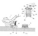
図1にはこの発明を具備する耕耘機の側面図が図示されている。耕耘機1の機体部を、ミッションケース2と、このミッションケース2の前側下部から前方に延出しているエンジンフレーム3と、ミッションケース2の後側部から後方斜め下方に延出している耕耘伝動ケース4とで構成し、ミッションケース2の後側上部から斜め後側後側上方にハンドル5を延出している。なお、ミッションケース2と耕耘伝動ケース4を一体構成とし、側面視でへ字型に構成している。
Embodiments of the present invention will be described below with reference to the drawings.
FIG. 1 shows a side view of a cultivator equipped with the present invention. The body part of thecultivator 1 includes atransmission case 2, an engine frame 3 that extends forward from the lower front side of thetransmission case 2, and a cultivating transmission that extends obliquely downward and rearward from the rear side part of thetransmission case 2. Thehandle 4 is configured to extend from the upper rear side of thetransmission case 2 to the upper rear side of the rear side. In addition, themission case 2 and thetillage transmission case 4 are configured as an integral unit, and are configured in a square shape in a side view.

そして、ミッションケース2の下端部に左右車輪6,6付きの左右車軸7,7を軸架し、耕耘伝動ケース4の下端部には左右耕耘軸32,32、耕耘爪等からなるロータリ耕耘装置8を設けている。エンジンフレーム3にはエンジン9を搭載し、エンジン9の回転動力をベルト伝動装置10を経由してミッションケース2に伝達し、ミッションケース2内の変速伝動装置(図示省略)により変速及び前後進を切り替え、前進走行動力及び後進走行動力を左右車輪7,7に伝達している。また、ミッションケース2の変速伝動装置(図示省略)から作業動力を分岐し、耕耘伝動ケース4内の耕耘伝動装置(図示省略)を経由してロータリ耕耘装置8に伝達し、ロータリ耕耘装置8を正転あるいは逆転するように構成している。  Then, left and right axles 7 and 7 with left andright wheels 6 and 6 are pivoted on the lower end portion of themission case 2, and the rotary tiller device including left andright tillage shafts 32 and 32, tillage claws and the like on the lower end portion of thetillage transmission case 4. 8 is provided. An engine 9 is mounted on the engine frame 3, the rotational power of the engine 9 is transmitted to thetransmission case 2 via thebelt transmission device 10, and the speed change and forward / reverse movement are performed by a transmission transmission device (not shown) in thetransmission case 2. Switching, forward travel power and reverse travel power are transmitted to the left and right wheels 7, 7. Further, the working power is branched from the transmission gear transmission (not shown) of thetransmission case 2 and transmitted to therotary tillage device 8 via the tillage transmission device (not shown) in thetillage transmission case 4. It is configured to rotate forward or reverse.

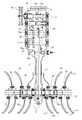
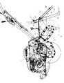
次に、図2に基づき耕耘伝動ケース4の伝動構成について具体的に説明する。図2には伝動構成の展開した切断正面図が図示されている。
ミッションケース2の上部には、左右方向の主軸11、走行伝動軸(図示省略)及び変速伝動軸13を側面視で三角形状に軸架し、エンジン9から前記ベルト伝動装置10を経て主軸11に動力を伝達している。
Next, the transmission configuration of thetillage transmission case 4 will be specifically described with reference to FIG. FIG. 2 shows an exploded front view of the transmission configuration.
In the upper part of thetransmission case 2, a main shaft 11 in the left-right direction, a travel transmission shaft (not shown) and atransmission transmission shaft 13 are mounted in a triangular shape in a side view, and from the engine 9 to the main shaft 11 through thebelt transmission device 10. Power is transmitted.

また、主軸11の右側部には一体構成の大小変速ギヤ14a,14bを軸方向に摺動自在にスプライン嵌合し、主軸11の左側部には主軸ギヤ15を固着している。また、変速伝動軸13の左側部には一体構成の大小耕耘変速ギヤ16a,16bを回転自在で且つ左右移動自在に設け、変速伝動軸13の右側部には、走行変速用の大小の変速ギヤ17a,17b及び後進ギヤ18を楔着している。  In addition, the large and smallspeed change gears 14a and 14b are spline-fitted to the right side of the main shaft 11 so as to be slidable in the axial direction, and themain shaft gear 15 is fixed to the left side of the main shaft 11. In addition, large and smalltillage transmission gears 16a and 16b are provided on the left side of thetransmission transmission shaft 13 so as to be rotatable and movable left and right, and on the right side of thetransmission transmission shaft 13 are large and small transmission gears for traveling transmission. 17a, 17b and thereverse gear 18 are wedged.

また、変速伝動軸13の下方には耕耘伝動軸20、逆転耕耘伝動軸21を軸架し、耕耘伝動軸20にはギヤ23を楔着し、変速伝動軸13の小耕耘変速ギヤ16bから耕耘伝動軸20のギヤ23、耕耘チエン伝動装置24を経て耕耘軸32,32に正転耕耘動力を伝達している。また、逆転耕耘伝動軸21にはギヤ25a,25bを設け、前記変速伝動軸13、耕耘伝動軸20及び逆転耕耘伝動軸21を側面視で三角形状をなすように配設して、変速伝動軸13の大耕耘変速ギヤ16aから逆転耕耘伝動軸21のギヤ25a及びギヤ25b、耕耘伝動軸20のギヤ23を経て耕耘チエン伝動装置24に逆転耕耘動力を伝達している。  Further, atillage transmission shaft 20 and a reversetillage transmission shaft 21 are mounted below thetransmission transmission shaft 13, agear 23 is wedged on thecultivation transmission shaft 20, and thetillage transmission gear 16 b of thetransmission transmission shaft 13 is cultivated. The forward tillage power is transmitted to thetillage shafts 32 and 32 through thegear 23 of thetransmission shaft 20 and the tillage chain transmission device 24. Further, the reversetillage transmission shaft 21 is provided withgears 25a and 25b, and thetransmission transmission shaft 13, thetillage transmission shaft 20 and the reversetillage transmission shaft 21 are arranged in a triangular shape in a side view, and the transmission transmission shaft. The reverse tillage power is transmitted from the 13 largetillage transmission gear 16 a to the tillage chain transmission device 24 through thegear 25 a andgear 25 b of the reversetillage transmission shaft 21 and thegear 23 of thetillage transmission shaft 20.

前記構成によると、耕耘シフタ(図示省略)により変速伝動軸13の耕耘変速ギヤ16a,16bを左右にシフトすることにより、正転耕耘動力、及び、逆転耕耘動力を耕耘軸32,32に伝達することができる。  According to the said structure, thetillage transmission gears 16a and 16b of the speedchange transmission shaft 13 are shifted right and left with a tillage shifter (illustration omitted), and normal rotation power and reverse rotation power are transmitted to thetillage shafts 32 and 32. be able to.

また、耕耘伝動ケース4の下部には左右耕耘伝動軸31,31を軸架し、左右耕耘伝動軸31,31には左右耕耘軸32,32をピン32a,…により固着連結し、左右耕耘軸32,32に設けた爪ホルダ33,…には、耕耘爪34,…をその先端屈曲部を左右外側に向けるようにして、ボルト・ナットで取り付けている。  Further, left and righttillage transmission shafts 31, 31 are mounted on the lower portion of thetillage transmission case 4, and the left and righttillage transmission shafts 31, 31 are connected to the left andright tillage shafts 32, 32 bypins 32a,. .. Are attached to theclaw holders 33,... Provided on the 32, 32 with bolts and nuts so that the bent portions of the tips are directed to the left and right outer sides.

また、耕耘爪34,…には、図2に示すように、正転耕耘(図1で反時計方向)時に、回転上手側の縁部の土中打ち込み位置に対して、回転下手側の縁部の土中打ち込み位置が左右内側に位置するように耕耘爪34,…に左右方向の傾斜面を構成し、また、逆転耕耘(図1の時計方向)時に、回転上手側の縁部の土中打ち込み位置に対して、回転下手側の縁部の土中打ち込み位置が左右外側に位置するように耕耘爪34,…に左右方向の傾斜面を構成し、全ての耕耘爪34,…の先端屈曲部を左右外側に向くように構成している。そして、左右耕耘軸32,32に取り付ける耕耘爪34,…のうち、内側に取り付ける例えば2本の耕耘爪34a,34aを、外側に取り付ける耕耘爪34b,…よりも、左右方向の前記傾斜面の傾斜角度を大きく構成している。なお、内側に位置する耕耘爪34cは、先端を耕耘伝動ケース4に接近すべく折り曲げて残耕を少なくさせている。なお、この耕耘爪34cを上記耕耘爪34aに代替してもよい。  Further, as shown in FIG. 2, thetilling claws 34,... Have a lower rotation side edge with respect to the position of the upper rotation side edge in the soil during forward rotation tillage (counterclockwise in FIG. 1). Thetilling claws 34,... Have a left and right inclined surface so that the position of the soil driven in the soil is on the left and right sides, and the soil at the edge on the upper rotation side during reverse tillage (clockwise in FIG. 1). Thetilling claws 34,... Have an inclined surface in the left-right direction so that the soiling position at the edge of the lower rotation side is located on the left and right outside of the middle driving position, and the tips of all thetilling claws 34,. The bent portion is configured to face the left and right outer sides. And, among thetilling claws 34 attached to the left andright tillage shafts 32, 32, for example, two tilling claws 34a, 34a attached on the inner side of theinclined claws 34b,. The inclination angle is large. In addition, the tilling claw 34c located on the inner side is bent to approach thetillage transmission case 4 to reduce the remaining tillage. The tilling claw 34c may be replaced with the tilling claw 34a.

前記構成によると、内側に取り付ける例えば2本の耕耘爪34a,…を、外側に取り付ける耕耘爪34b,…よりも、左右方向の傾斜面の傾斜角度を大きく構成しているので、逆転耕耘時には、耕耘伝動ケース4に近い内側の土を左右外側に大きく飛ばすことができ、耕耘伝動ケース4の下方を溝とし左右両側に大きく盛り上がる畦を形成することができる。  According to the above configuration, for example, the two tilling claws 34a attached to the inner side are configured to have a larger inclination angle of the inclined surface in the left-right direction than thetilling claws 34b attached to the outer side. The inner soil close to thetillage transmission case 4 can be greatly blown to the left and right outer sides, and canopies can be formed that rise greatly on the left and right sides with the lower part of thetillage transmission case 4 as a groove.

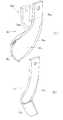
次に、図3及び図4に基づきロータリ耕耘装置8の他の実施形態について説明する。
左右耕耘軸32,32の内側寄りには、例えば3本の凹状板体爪36,…を、その凹み部を左右外側に向けて配設し、左右両側寄りには例えば4本のなた爪37,…を、その先端屈曲部37bを左右外側に向けるように取り付けている。
Next, another embodiment of therotary tiller 8 will be described with reference to FIGS. 3 and 4.
For example, threeconcave plate claws 36 are arranged near the inner sides of the left andright tillage shafts 32, 32, and the concave portions thereof are directed to the left and right outer sides. 37,... Are attached so that thebent end portions 37b thereof face left and right.

前記凹状板体爪36は、図4(A)に示すように、基部を幅狭とし先端側を幅広とした板体で構成し、板体を側面視(板面に直交する方向)で正転時の回転上手側縁部を先端側ほど回転下手側に順次屈曲して構成し、板体の回転方向上手側縁部に刃部36aを形成している。そして、回転上手側から回転方向中途部にかけて左右一側に向けて脹らみ、中途部から回転下手側にかけて順次閉じる凹部36bを構成し、凹状板体爪36の先端部には前記凹部36bを閉じるように屈曲部36cに構成し、板体の回転方向下手側端縁には板面に直交する切断面36d(あるいは刃部)を構成している。  As shown in FIG. 4A, theconcave plate claw 36 is formed of a plate having a narrow base and a wide tip, and the plate is viewed from the side (in a direction perpendicular to the plate surface). The rotating upper side edge at the time of rolling is sequentially bent toward the lower rotating side toward the distal end side, and ablade 36a is formed at the upper edge of the plate in the rotational direction. Then, aconcave portion 36b is formed which swells toward the left and right sides from the upper rotation side to the middle in the rotation direction, and sequentially closes from the middle portion to the lower rotation side, and theconcave portion 36b is formed at the tip of theconcave plate claw 36. Abent portion 36c is formed so as to be closed, and acutting surface 36d (or a blade portion) orthogonal to the plate surface is formed at the lower edge in the rotational direction of the plate body.

なお、凹状板体爪36を、基部及び先端部を幅狭で中途部を幅広の板体で構成してもよく、また、凹状板体爪36,…の基部に左右一側に屈折する屈折部36eを付加し、爪ホルダ33に取り付けた基部側に対して先端側を左右一側に偏位するように屈折凹状板体爪36fとしてもよい。  Theconcave plate claw 36 may be constituted by a plate having a narrow base portion and a tip portion and a wide middle portion, and a refraction that is refracted to the left and right sides at the base portion of theconcave plate claw 36. It is good also as a refractive concave plate-shaped nail | claw 36f to add thepart 36e and to deviate the front end side to the left-right one side with respect to the base side attached to thenail holder 33.

また、前記なた爪37,…は、図4(B)に示すように、幅狭の板体で構成し、板体の側面視で先端側を回転下手側に屈曲構成し、板体の回転方向上手側縁部に刃部37aを形成し、板体の基部から先端にわたる部分を平面状とし、先端部に左右一側に向けて屈曲する屈曲部37bを構成している。  Further, as shown in FIG. 4 (B), the above-mentionednails 37,... Are constituted by a narrow plate body, and the tip end side is bent toward the rotating lower side in a side view of the plate body. A blade portion 37a is formed on the upper edge portion in the rotational direction, a portion extending from the base portion to the tip of the plate body is planar, and abent portion 37b that is bent toward the left and right sides is formed at the tip portion.

前記構成によると、左右耕耘軸32,32の内側部に凹状板体爪36,…を、その凹部36bを外側に向けるように取り付け、左右耕耘軸32,32の外側部に普通のなた爪37を配設している。この状態で逆転耕耘をすると、内側部の凹状板体爪36,…により土の下部を凹部36bに抱え込みながら左右外側に大きく飛ばすことができ、耕耘伝動ケース4下方の残土を少なくしながら、左右両側に高い畦を形成することができる。  According to the above configuration, theconcave plate claws 36,... Are attached to the inner portions of the left andright tillage shafts 32, 32 so that therecess portions 36b are directed outward, and the ordinary nails are attached to the outer portions of the left andright tillage shafts 32, 32. 37 is disposed. When reverse tillage is performed in this state, theconcave plate claws 36,... On the inner side can be largely blown to the left and right while holding the lower part of the soil in therecess 36b, and the left and right sides are reduced while reducing the remaining soil below thetillage transmission case 4. High ridges can be formed on both sides.

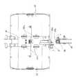
次に、図5に基づきロータリ耕耘装置8の他の実施形態について説明する。
左右耕耘軸32,32の内側寄りには、例えば4本のなた爪37,…をその先端屈曲部37bを左右内側に向けて屈曲するように取り付け、左右両側寄りには、例えば2本の凹状板体爪36,…及び1本の屈折凹状板体爪36fを、その凹部36bを内側に向けて取り付けている。
Next, another embodiment of therotary tiller 8 will be described with reference to FIG.
.. Are attached to the inner sides of the left andright tillage shafts 32, 32, for example, so that the tip bentportions 37 b are bent toward the left and right inner sides. Theconcave plate claw 36,... And one refractiveconcave plate claw 36f are attached with theconcave portion 36b facing inward.

前記構成によると、内側に普通のなた爪37、…を配設し、外側に凹状板体爪36,…、屈折凹状板体爪36fを配設した状態で、正転耕耘をする。すると、内側のなた爪37,…により内側下部の土を左右内側に飛ばし、外側の凹状板体爪36,…及び屈曲凹状板体爪により、外側下部の土を凹部36bにより抱え込みながら内側に大きく飛ばし、左右両側への土のこぼれを少なくしながら、耕耘伝動ケース4の下方に内盛り状の幅広の畦を形成することができる。  According to the above-described configuration, normal tilling is performed in a state where theordinary nail 37,... Are disposed on the inner side, and theconcave plate claw 36,. Then, the innerlower nail 37,... Scatters the inner lower soil to the left and right inner sides, and the outerconcave plate nail 36,... And the bent concave plate nail holds the outer lower soil in therecess 36b. It is possible to form a wide paddle with a built-in shape below thetillage transmission case 4 while greatly skipping and reducing soil spillage on the left and right sides.

次ぎに、図6に基づきロータリ耕耘装置8の他の実施形態について説明する。
左右耕耘軸32,32には、板体爪36h,…の先端屈曲部36iを左右外側に向けて配設している。そして、この板体爪は、図6(B)に示すように、板体の基端側を回転方向に狭く、基端部から中途部にかけて順次回転方向に広く構成し、中途部から先端部にかけて順次狭くなるように構成し、先端部を左右一側に屈曲する先端屈曲部36iに構成している。
Next, another embodiment of therotary tiller 8 will be described with reference to FIG.
The left andright tillage shafts 32, 32 are provided withbent end portions 36i of theplate claws 36h,. As shown in FIG. 6 (B), the plate body claw is configured such that the base end side of the plate body is narrow in the rotation direction, and is gradually widened in the rotation direction from the base end portion to the midway portion. The tip end portion is configured as atip bend portion 36i that bends to the left and right sides.

また、板体の中途部には、回転方向一端から回転方向中途部にかけて先端屈曲部36iの屈曲方向に向けて順次脹らみ、中途部から回転方向他端側に向けて脹らみを順次閉じるような脹らみ部36kを構成し、そして、この脹らみ部36kの脹らみ傾斜角度βを、図6(B)に示すように、左右耕耘軸32,32の軸心線に直交する基準面に対して、例えば8度傾斜するように設定している。  Further, in the middle part of the plate body, the bulge is sequentially expanded from one end in the rotational direction to the middle part in the rotational direction toward the bending direction of thetip bending part 36i, and the bulge is sequentially performed from the middle part toward the other end in the rotational direction. A bulgingportion 36k that closes is formed, and the bulging inclination angle β of the bulgingportion 36k is set to the axis of the left andright tillage shafts 32 and 32 as shown in FIG. For example, it is set to be inclined by 8 degrees with respect to the orthogonal reference plane.

また、左右耕耘軸32,32に板体の爪ホルダ33を取り付けるにあたり、左右耕耘軸32,32の軸心線に直交する基準面に対して、図6(B)に示すように、爪ホルダ33の板体の回転方向上手側を傾斜角度α、例えば5度左右外側に傾斜するように取り付けて、傾斜角度α<傾斜角度βとなるように設定している。  Further, when attaching the plate-shapedclaw holder 33 to the left andright tillage shafts 32, 32, as shown in FIG. The upper side of the 33 plate bodies in the rotational direction is attached so as to incline to the outside at an inclination angle α, for example, 5 degrees left and right, and the inclination angle α <the inclination angle β is set.

前記構成によると、正転耕耘時には、板体爪36hの打ち込み回転上手側部分では、略真っ直ぐに土中に入り込み、土を左右外側へ移動させずに耕耘することができる。また、逆転耕耘時には、板体爪36hの打ち込み回転上手側部分では、爪ホルダ33の前記傾斜角度α及び板体爪36hの前記傾斜角度βにより、脹らみ部36kの大きく傾斜した外側面により、土を左右外側に大きく移動しながら土中に入り込み、また、これに続く板体爪36hの回転下手側部分が土中から抜けるときには、回転下手側部分では、脹らみ部36kの外側面と先端屈曲部36iとの共同作用により、土を左右外側に大きく放擲して盛り上げ、耕耘伝動ケース4の下方に大きな溝を形成しながら、左右両側に大きく盛り上がった畦を形成することができる。  According to the above configuration, at the time of forward tillage, the upper portion of theplate claw 36h that is driven to rotate can enter the soil substantially straight and can be tilled without moving the soil left and right. Further, at the time of reverse plowing, theplate claw 36h is driven and rotated on the upper side by the inclined surface α of theclaw holder 33 and the inclined angle β of theplate claw 36h, due to the greatly inclined outer surface of the swellingportion 36k. When the lower side portion of theplate claw 36h moves out of the soil, the outer side surface of the bulgingportion 36k is removed from the lower side portion of theplate claw 36h. And thetip bending portion 36i can swell the soil largely to the left and right outside to form a large groove below thetillage transmission case 4, while forming a large ridge on both the left and right sides. .

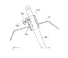
次に、図7乃至図10に基づき耕耘カバー42、抵抗棒44及び尾輪45部分の構成について説明する。
耕耘伝動ケース4の上部から後方に向けて耕耘フレーム41を延出し、耕耘フレーム41には左右耕耘カバー42,42の内側部をヒンジ42a,…により支持し、畦立て作業時には左右耕耘カバー42,42の左右両側を上方に回動した開放状態とし、また、通常の平面耕耘作業時には、左右耕耘カバー42,42を下方に回動した閉鎖状態にするように構成している。
Next, the configuration of the tillingcover 42, theresistance rod 44, and thetail wheel 45 will be described with reference to FIGS.
A tillingframe 41 extends rearward from the top of thetillage transmission case 4, and the inside of the left and right tillage covers 42, 42 is supported on the tillingframe 41 byhinges 42a,... The left and right sides of 42 are in an open state rotated upward, and the left and right tillage covers 42 and 42 are closed in a closed state during normal flat tillage work.

また、耕耘フレーム41の後部には前後支持筒体43a,43bを上下方向に沿わせて取り付け、前支持筒体43aには抵抗棒44を支持し、操作具44aにより抵抗棒44を上下調節可能に構成している。なお、抵抗棒44の下端部には土中に食い込む抵抗部44bを設け、抵抗棒44の中途部には浮力板44cを設けている。また、後支持筒体43bには尾輪45付きの尾輪支持棒46を上下調節自在に支持している。  Also, front andrear support cylinders 43a and 43b are attached to the rear part of the tillingframe 41 along the vertical direction, aresistance bar 44 is supported on thefront support cylinder 43a, and theresistance bar 44 can be adjusted up and down by theoperation tool 44a. It is configured. Aresistance portion 44b that bites into the soil is provided at the lower end portion of theresistance rod 44, and abuoyancy plate 44c is provided in the middle portion of theresistance rod 44. Further, a tailwheel support rod 46 with atail wheel 45 is supported on therear support cylinder 43b so as to be vertically adjustable.

また、前支持筒体43aには前後方向に沿わせて筒体状の保持具47を設け、前記後支持筒体43bから取り外した尾輪支持棒46を保持具47により支持し、ロータリ耕耘装置8の上方に収納できるように構成している。  Further, thefront support cylinder 43a is provided with acylindrical holder 47 along the front-rear direction, the tailwheel support rod 46 removed from therear support cylinder 43b is supported by theholder 47, and a rotary tiller is provided. 8 is configured so that it can be stored above 8.

前記構成によると、後支持筒体43bから取り外した尾輪45付き尾輪支持棒46を保持具47により支持して、ロータリ耕耘装置8の上方に収納することにより、耕耘土壌に尾輪45の跡を付けずにきれいな耕耘仕上りとすることができる。また、逆転耕耘による畦立て作業や、耕耘機1の移動時には、尾輪45を上下調節しながら使用し、これら作業を楽にすることができる。また、尾輪45の前方に抵抗棒44を設けているので、逆転耕耘による畦立て作業時に耕耘伝動ケース4の下方に残耕が生じても、抵抗棒44により削り取ることができ、耕耘跡をきれいに仕上げることができる。  According to the said structure, the tailwheel support rod 46 with thetail wheel 45 removed from theback support cylinder 43b is supported by theholder 47, and is accommodated above therotary tillage device 8, so that thetail wheel 45 can be put in the cultivation soil. It can be a beautiful tillage without any traces. In addition, thetail wheel 45 can be used while being adjusted up and down during the upright work by reverse tillage or when thecultivator 1 is moved, so that these work can be facilitated. Further, since theresistance rod 44 is provided in front of thetail wheel 45, even if residual tilling occurs below thetillage transmission case 4 during the upsetting work by reverse tillage, theresistance rod 44 can scrape off the tillage track. It can be finished neatly.

また、図11及び図12に示すように構成してもよい。耕耘フレーム41の後部には前後支持筒体43a,43bを設け、前支持筒体43aには抵抗棒44を操作具44aにより上下調節自在に支持している。耕耘フレーム41に後支持筒体43bを左右方向の軸回りに回動調節自在に支持し、この後支持筒体43bに尾輪45付きの尾輪支持棒46を上下回動自在に支持している。  Moreover, you may comprise as shown in FIG.11 and FIG.12. Front andrear support cylinders 43a and 43b are provided at the rear portion of thetillage frame 41, and aresistance rod 44 is supported on thefront support cylinder 43a by anoperating tool 44a so as to be adjustable up and down. Arear support cylinder 43b is supported on thetillage frame 41 so as to be rotatable around a horizontal axis, and a tailwheel support rod 46 with atail wheel 45 is supported on thesupport cylinder 43b so as to be rotatable up and down. Yes.

そして、尾輪保持具48により、尾輪支持棒46を上下方向に沿わせた尾輪45の使用状態、また、尾輪支持棒46を前後方向に沿わせ尾輪45を上方に収納した状態に、変更できるように構成している。  Then, the tailwheel support rod 46 is used in the up and down direction by thetail wheel holder 48, and thetail wheel 45 is stored in the up and down direction, and thetail wheel 45 is stored in the upper and lower direction. It is configured so that it can be changed.

なお、尾輪保持具48は、耕耘フレーム41に左右方向のボルト・ナット48aで軸支されている保持板48bと、耕耘フレーム41側の支持孔48cと、保持板48b側の複数の調節孔48dと、これらの孔48c,48d,…に挿入するピン48eとにより構成し、保持板48bの後側端部に後支持筒体43bを取り付けている。しかして、保持板48b側の複数の調節孔48d,…にピン48eを選択挿入することにより、尾輪45を使用状態、あるいは、収納状態に変更支持する構成である。前記構成によると、前記実施形態と同様の作用効果が期待できる。  Thetail wheel holder 48 includes a holding plate 48b that is pivotally supported on the tillingframe 41 by bolts and nuts 48a in the left-right direction, asupport hole 48c on the tillingframe 41 side, and a plurality of adjustment holes on the holding plate 48b side. 48d and pins 48e inserted into theseholes 48c, 48d,..., And arear support cylinder 43b is attached to the rear end of the holding plate 48b. Thus, by selectively insertingpins 48e into the plurality ofadjustment holes 48d,... On the holding plate 48b side, thetail wheel 45 is changed and supported in the use state or the storage state. According to the said structure, the effect similar to the said embodiment can be anticipated.

また、図13のように構成してもよい。すなわち、後支持筒体43bは、支持板51の案内ガイド51aに沿って移動固定でき(図13中(イ))、ガイドの後端側において適宜ピン止め等によって固定することで尾輪45を使用状態とし、固定を解除して反転させつつ(同図中(ロ)(ハ))、ガイド51aに沿って前方にスライドさせることによって該ガイド51aの前端に達し(同図中(ニ))、ここで適宜にピン止め等によって固定することで収納状態にすることができる。このように構成すると、収納状態の尾輪位置が前方に寄せられてハンドル操作するオペレータの邪魔になり難い。  Moreover, you may comprise as FIG. That is, therear support cylinder 43b can be moved and fixed along theguide guide 51a of the support plate 51 ((a) in FIG. 13), and thetail wheel 45 can be fixed by appropriately fixing the pin on the rear end side of the guide. In the use state, the front end of theguide 51a is reached by sliding forward along theguide 51a while releasing and reversing the fixation ((b) (c) in the figure) ((d) in the figure). Here, it can be put in a housed state by being fixed by pinning or the like as appropriate. If comprised in this way, the tail wheel position of a stowed state will be brought forward, and it will be hard to get in the way of the operator who operates a handle.

また、抵抗棒44及び尾輪支持棒46の上下調節構成を図14のように構成してもよい。耕耘フレーム41の後部には前後支持筒体43a,43bを設け、前支持筒体43aには抵抗棒44を抵抗棒上下調節装置49により上下調節可能に支持し、後支持筒体43bには、尾輪45付きの尾輪支持棒46を尾輪上下調節装置50により上下調節自在に支持している。  Further, the vertical adjustment configuration of theresistance rod 44 and the tailwheel support rod 46 may be configured as shown in FIG. Front andrear support cylinders 43a and 43b are provided at the rear portion of thetillage frame 41. Aresistance bar 44 is supported on thefront support cylinder 43a by a resistance barvertical adjustment device 49 so that the vertical adjustment is possible. A tailwheel support rod 46 with atail wheel 45 is supported by a tail wheelvertical adjustment device 50 so as to be adjustable in the vertical direction.

抵抗棒上下調節装置49は、外周部にねじを形成したねじ棒49aと、抵抗棒44の上端に取り付けられていて、内周部にねじ溝を形成したねじ筒体49bと、ねじ棒49aに固着しているギヤ49cとにより構成している。また、尾輪上下調節装置50は、外周部にねじ(ねじ棒49aのねじとは逆方向)を形成したねじ棒50aと、尾輪支持棒46の上端に取り付けられていて、内周部にねじ溝を形成したねじ筒体50bと、ねじ棒50aに固着しているギヤ50cと、ねじ棒50aの上端部に取り付けたハンドル50dとにより構成し、ギヤ49cとギヤ50cとを噛み合わせて、尾輪45及び抵抗棒44を同じ方向に上下調節できるように構成している。  The resistance rod up / downadjustment device 49 includes a screw rod 49a having a screw formed on the outer periphery thereof, a screw cylinder 49b attached to an upper end of theresistance rod 44 and having a screw groove formed on the inner periphery thereof, and a screw rod 49a. The gear 49c is fixed. The tail wheel up / down adjustingdevice 50 is attached to the upper end of a threadedrod 50a having a screw (in the direction opposite to the screw of the threaded rod 49a) on the outer periphery and the tailwheel support rod 46, and is attached to the inner periphery. A threadedcylinder 50b having a thread groove, agear 50c fixed to the threadedrod 50a, and ahandle 50d attached to the upper end of the threadedrod 50a, the gear 49c and thegear 50c are meshed, Thetail wheel 45 and theresistance rod 44 are configured to be vertically adjustable in the same direction.

前記構成によると、耕耘作業時に、ハンドル50dを操作し尾輪45を上下調節し耕深調節をすると、抵抗棒44も関連的に同位置に上下調節される。従って、逆転耕耘による畦立て作業時には、尾輪45及び抵抗棒44を共に上下調節し、耕耘伝動ケース4の下方に生じる残耕を抵抗棒44により削り取り耕耘跡をきれいに仕上げることができ、また、尾輪45が残耕に乗り上げることもなく楽に直進耕耘することができる。  According to the above-described configuration, when thehandle 50d is operated to adjust thetail wheel 45 up and down and the tilling depth is adjusted during the tilling operation, theresistance rod 44 is also related to the same position. Therefore, at the time of upsetting by reverse tillage, both thetail wheel 45 and theresistance rod 44 can be adjusted up and down, and the residual tillage generated below thetillage transmission case 4 can be scraped off by theresistance rod 44 to finish the tilling trace cleanly. Thetail wheel 45 can be straightly cultivated easily without riding up afterglow.

次に、図15に基づき尾輪構成の他の実施形態について説明する。
耕耘フレーム41の後部の後支持筒体43bには、尾輪支持棒46を上下調節自在に支持し、尾輪支持棒46の下端には左右方向に沿うように尾輪軸45aを延出し、尾輪軸45aの両端に左右尾輪45,45を軸支している。そして、尾輪軸45aの両端部には左右ねじ孔45b,45bを構成し、キャップ45c,45cにより左右ねじ孔45b,45bを閉鎖可能に構成し、尾輪支持棒46の左右両側に畦肩部を削り取る左右肩削り装置52,52を設けている。
Next, another embodiment of the tail wheel configuration will be described based on FIG.
A tailwheel support rod 46 is supported on therear support cylinder 43b of the rear portion of thetillage frame 41 so that the tailwheel support rod 46 can be adjusted up and down, and atail wheel shaft 45a extends along the left-right direction at the lower end of the tailwheel support rod 46. Left andright tail wheels 45, 45 are pivotally supported at both ends of thewheel shaft 45a. The left and right screw holes 45b and 45b are formed at both ends of thetail wheel shaft 45a, and the left and right screw holes 45b and 45b can be closed by thecaps 45c and 45c. Left and rightshoulder shaving devices 52, 52 are provided.

この左右肩削り装置52,52は、後支持筒体43bに後方に突出するように着脱自在に取り付けるフレーム52aと、フレーム52aの左右両側に位置する左右肩削り板52b,52bと、前記尾輪軸45aの左右ねじ孔45b,45bに左右肩削り板52b,52bの下端部を左右方向突出調節自在に支持する左右支持体52c,52cと、フレーム52aに左右肩削り板52b,52bの上部を左右方向突出調節自在に取り付ける左右前支持アーム52d,52d、左右後側支持アーム52e,52eとにより構成している。  The left and rightshoulder shaving devices 52, 52 include aframe 52a that is detachably attached to therear support cylinder 43b so as to protrude rearward, left and rightshoulder shaving plates 52b, 52b located on the left and right sides of theframe 52a, and the tail wheel shaft. Left andright support bodies 52c and 52c for supporting the lower end portions of the left and rightshoulder shaving plates 52b and 52b so that the left and right shoulders can be freely adjusted in the left and right screw holes 45b and 45b, and the upper portions of the left and rightshoulder shaving plates 52b and 52b on theframe 52a The left and rightfront support arms 52d and 52d and the left and rightrear support arms 52e and 52e are mounted so as to be freely adjustable in the direction of protrusion.

前記構成によると、左右肩削り板52b,52bを畦の傾斜面に接触するように調節して取り付け、ロータリ耕耘装置8を逆転耕耘しながら畦立て作業をする。すると、左右尾輪45,45は耕耘伝動ケース4の後方を走行しながらロータリ耕耘装置8を所定耕耘深度に規制し、後続して肩削り装置52が移動すると、左右肩削り板52b,52bにより畦の左右肩部の土を削り取り、土のこぼれの少ない畦を形成することができる。  According to the above configuration, the left and rightshoulder shaving plates 52b, 52b are adjusted and attached so as to be in contact with the inclined surface of the ridge, and the vertical tilling operation is performed while therotary cultivator 8 is reversely cultivated. Then, the left andright tail wheels 45, 45 regulate therotary tiller 8 to a predetermined tillage depth while traveling behind thetillage transmission case 4, and when theshoulder shaving device 52 subsequently moves, the left and rightshoulder shaving plates 52b, 52b The soil on the left and right shoulders of the reed can be scraped off to form a reed with little soil spillage.

また、左右肩削り板52c,52cの左右傾斜角度調節をする左右前支持アーム52d,52dは、長孔52e,52eにより左右突出度を調節し、また、左右後側支持アーム52e,52eは複数の独立した調節孔により左右突出度を調節するので、調節操作を簡単化しながら、左右肩削り板52b,52bを所定の傾斜角度に強固に調節支持することができる。  The left and rightfront support arms 52d and 52d for adjusting the left and right inclination angles of the left and rightshoulder shaving plates 52c and 52c adjust the degree of left and right protrusions by thelong holes 52e and 52e, and the left and rightrear support arms 52e and 52e are plural. Therefore, the left and rightshoulder shaving plates 52b and 52b can be firmly adjusted and supported at a predetermined inclination angle while simplifying the adjustment operation.

また、抵抗棒44の上下調節装置を図16に示すように構成してもよい。耕耘フレーム41の支持筒体43aには、抵抗棒44を上下動自在に挿入支持し、前支持筒体43aの筒体の径よりも抵抗棒44の径を小径にして上下移動を容易にしている。支持筒体43aには上下調節用の調節ボルト54a、調節ナット54bを取り付け、抵抗棒44には複数の調節凹部54c,…を設けている。  Moreover, you may comprise the vertical adjustment apparatus of theresistance bar 44 as shown in FIG. Theresistance rod 44 is inserted and supported in thesupport cylinder 43a of the tillingframe 41 so as to be movable up and down, and the diameter of theresistance rod 44 is made smaller than the diameter of the cylinder of thefront support cylinder 43a to facilitate vertical movement. Yes. Avertical adjustment bolt 54a and anadjustment nut 54b are attached to thesupport cylinder 43a, and a plurality ofadjustment recesses 54c,.

前記構成によると、調節ボルト54aの先端を抵抗棒44の複数の調節凹部54c,…に選択嵌合しねじ込むことにより、抵抗棒44の上下調節及び振れ止めを一挙にすることができる。  According to the above configuration, by vertically fitting and screwing the tip of theadjustment bolt 54a into the plurality ofadjustment recesses 54c,...

次に、図17及び図18に基づきロータリ耕耘装置8の耕耘カバー42の他の実施形態について説明する。
耕耘伝動ケース4の上部から後方に向けて板状の耕耘フレーム41を延出してロータリ耕耘装置8の中央部上方を覆い、耕耘フレーム41の左右両側部には左右耕耘カバー42,42をヒンジ42a,…により支持し、畦立て作業時には左右耕耘カバー42,42の左右両側を上方に回動した開放状態とし、また、通常の平面耕耘作業時には、左右耕耘カバー42,42を下方に回動しロータリ耕耘装置8の左右両側部を覆う閉鎖状態にするように構成している。
Next, another embodiment of the tillingcover 42 of therotary tiller 8 will be described with reference to FIGS. 17 and 18.
A plate-shapedtillage frame 41 extends rearward from the top of thetillage transmission case 4 to cover the upper center of therotary tiller 8, and left and right tillage covers 42, 42 are hinged 42a on the left and right sides of thetillage frame 41. ,... Are supported in an open state in which the left and right tillage covers 42 and 42 are rotated upward during the vertical work, and the left and right tillage covers 42 and 42 are rotated downward during the normal flat field work. It is comprised so that it may be in the closed state which covers the right-and-left both sides of therotary tillage apparatus 8. FIG.

左右耕耘カバー42,42の後部には左右リヤーカバー56,56を垂れ下がり状に取り付けて、ロータリ耕耘装置8の左右後部を覆っている。また、板状の耕耘フレーム41の後部を左右耕耘カバー42,42の後端部よりも少し後方まで延出し、この延出部にゴム等の柔軟性材からなる整地板57を吊り下げ状に取り付けて、ロータリ耕耘装置8の後側中央部を覆うようにし、この整地板57の下部に加圧板58を取り付け、整地板57を下方に押圧するようにしている。また、左右リヤーカバー56,56と整地板57を背面視で左右にオーバーラップさせ、耕土の飛散を防止している。  Left and right rear covers 56, 56 are attached to the rear portions of the left and right tillage covers 42, 42 to cover the left and right rear portions of therotary tiller 8. Further, the rear portion of the plate-shapedtillage frame 41 extends slightly rearward from the rear end portions of the left and right tillage covers 42, 42, and a levelingplate 57 made of a flexible material such as rubber is suspended from the extending portion. It attaches so that the center part of the rear side of therotary tiller 8 may be covered, and apressure plate 58 is attached to the lower part of the levelingplate 57 to press the levelingplate 57 downward. Further, the left and right rear covers 56, 56 and the levelingplate 57 are overlapped left and right in the rear view to prevent scattering of cultivated soil.

正転耕耘しながら耕耘作業をすると、ロータリ耕耘装置8の耕耘爪34,…の配列の関係で、中央部に盛り上がる部分が生じる場合がある。前記構成によると、中央部の盛り上がり部分を整地板57及び加圧板58により押さえ付けて平坦としきれいに仕上げることができる。また、ロータリ耕耘装置8の中央部後方への土や石の飛び出しを防ぎ、オペレータの保護を図ることができる。  When a tilling operation is performed while normal tilling, there is a case where a portion that rises in the center portion is generated due to the arrangement of the tillingclaws 34 of therotary tiller 8. According to the above configuration, the raised portion at the center can be pressed flat by the levelingplate 57 and thepressure plate 58 to be flat and clean. Further, it is possible to prevent the soil and stones from jumping out to the rear of the central portion of therotary tiller 8, thereby protecting the operator.

図17において、仮想線にて示す構成の抵抗棒60は、途中屈折部60aを形成してなる。抵抗棒は通常直線状に形成されるから、ホルダ61の係止から開放されるとこのホルダ61に沿って一挙に上下動可能となり、上動の際には、ハンドルに衝突する構成となっている。作業中ホルダ61に係止するが係止具62が緩むなどして係止状態が緩くなるため下方からの突き上げ作用によっては抵抗棒がハンドルに衝突して破損や怪我の原因となる恐れがあるが、抵抗棒60が突き上げられその屈折部60aがホルダ61に達するとストッパとなってそれ以上の上動を規制する。したがって、ハンドルへの衝接を防ぐことができる。  In FIG. 17, theresistance bar 60 having a configuration indicated by an imaginary line is formed with a halfway refraction portion 60 a. Since the resistance rod is usually formed in a straight line shape, it can be moved up and down along the holder 61 when released from the locking of the holder 61, and collides with the handle when moving up. Yes. Although it is locked to the holder 61 during operation, the locking state is loosened due to loosening of thelocking tool 62 or the like, so that the resistance rod may collide with the handle and cause damage or injury due to the push-up action from below. However, when theresistance rod 60 is pushed up and its refracting portion 60a reaches the holder 61, it acts as a stopper and restricts further upward movement. Therefore, the collision with the handle can be prevented.

図19は、耕耘機の変速レバーのガイドの一例を示すものである。従来変速レバーaを直線状ガイド溝bの途中変速位置を認識させるために、ガイド溝側に径大の皿状体落ち込み部cを形成し、変速レバーa側に皿状体eとスプリングfをもって皿状体eがガイドの落ち込み部cに達することにより、その位置を認識できる構成としていた。しかしながら、部品点数が多く破損損耗の恐れが多く改善が求められている。そこで、ガイド溝65の幅を変速レバー67の径よりも大きく形成し、ガイド溝65の途中において上下方向(直線シフト方向と直交する方向)にストロークを生じさせ、直線シフトの途中には凹部66を形成してなる。このように構成すると、直線ガイド溝65に沿って変速レバー67を移動操作するとき、凹部66に達すると距離α分落ち込んで係止し、オペレータはこの係止時の感覚で途中変速位置(図例では「低速」位置)に達したものと判断できる。ガイド溝65の形状を改良するのみでよいから安価に提供できる(図20)。  FIG. 19 shows an example of a shift lever guide of a field cultivator. In order for the conventional speed change lever a to recognize the mid-speed shift position of the linear guide groove b, a large-diameter dish-like body drop portion c is formed on the guide groove side, and the dish-like body e and the spring f are provided on the speed change lever a side. It was set as the structure which can recognize the position when the plate-shaped object e reaches the depression part c of a guide. However, the number of parts is large and there is a high risk of damage and wear. Therefore, the width of the guide groove 65 is formed larger than the diameter of thespeed change lever 67, and a stroke is generated in the vertical direction (direction orthogonal to the linear shift direction) in the middle of the guide groove 65, and therecess 66 is in the middle of the linear shift. Formed. With this configuration, when theshift lever 67 is moved along the straight guide groove 65, when theshift lever 67 is reached, the shift is lowered by the distance α when theshift lever 67 is reached. In the example, it can be determined that the “low speed” position has been reached. Since only the shape of the guide groove 65 needs to be improved, it can be provided at a low cost (FIG. 20).

1 耕耘機
4 耕耘伝動ケース
8 ロータリ耕耘装置
32 左右耕耘軸
34 耕耘爪
36 凹状板体爪
36b 凹部
36h 板体爪
36i 先端屈曲部
37 なた爪
41 耕耘フレーム
42 耕耘カバー
42a ヒンジ
DESCRIPTION OFSYMBOLS 1Tiller 4Tillage transmission case 8Rotary tiller 32 Left andright tillage shaft 34Tillage claw 36 Recessedplate claw 36b Recessedpart 36hPlate body claw 36iTip bending part 37Tail claw 41Cultivation frame 42Cultivation cover 42a Hinge

Claims (1)

Translated fromJapanese
耕耘伝動ケース(4)の下部左右に、耕耘軸(32,32)を設け、該左右耕耘軸(32,32)には耕耘爪(34,…)をその先端屈曲部を左右外側に向けるように取り付けて、左右耕耘軸(32,32)の正転耕耘時には略平面に形成する耕耘を行い、逆転耕耘時には耕耘伝動ケース(4)に近い側の土を左右外側に放擲し畦を形成する耕耘を行うよう構成し、耕耘伝動ケース(4)の上部から後方に向けて板状の耕耘フレーム(41)を延出してロータリ耕耘装置(8)の中央部上方を覆い、耕耘フレーム(41)の左右両側部に左右耕耘カバー(42,42)をヒンジ(42a,42a)により支持し、
前記左右耕耘カバー(42,42)の後部に左右リヤーカバー(56,56)を垂れ下がり状に取り付け、前記耕耘フレーム(41)の後部を左右耕耘カバー(42,42)の後端部よりも後方まで延出しこの延出部にゴム等の柔軟性材からなる整地板(57)を吊り下げ状に取り付け、この整地板(57)の下部に加圧板(58)を取り付けてなるロータリ耕耘装置。
The tilling shafts (32, 32) are provided on the lower left and right of the tillage transmission case (4), and the tilling claws (34,...) Are directed to the left and right outside of the left and right tilling shafts (32, 32). To the left and right tillage shafts (32, 32) during normal rotation tillage, forming a substantially flat tillage, and reverse rotation tilling the soil near the tillage transmission case (4) to the left and right outside to form a straw The plate-shaped tilling frame (41) is extended from the top of the tillage transmission case (4) to the rear to cover the upper part of the center of the rotary tilling device (8), and the tilling frame (41 The left and right tillage covers (42, 42) are supported by hinges (42a, 42a) on the left and right sides of
Left and right rear covers (56, 56) are attached to the rear part of the left and right tillage covers (42, 42) in a hanging manner, and the rear part of the tillage frame (41) is located behind the rear end of the left and right tillage covers (42, 42). A rotary tilling device inwhich a leveling plate (57) made of a flexible material such as rubber is attached to the extension part in a suspended manner, and a pressure plate (58) is attached to the lower part of the leveling plate (57) .
JP2009222754A2009-09-282009-09-28 Rotary tillage deviceExpired - Fee RelatedJP5051202B2 (en)

Priority Applications (1)

Application NumberPriority DateFiling DateTitle
JP2009222754AJP5051202B2 (en)2009-09-282009-09-28 Rotary tillage device

Applications Claiming Priority (1)

Application NumberPriority DateFiling DateTitle
JP2009222754AJP5051202B2 (en)2009-09-282009-09-28 Rotary tillage device

Related Parent Applications (1)

Application NumberTitlePriority DateFiling Date
JP2006235026ADivisionJP5050451B2 (en)2006-08-312006-08-31 Rotary tillage device

Publications (2)

Publication NumberPublication Date
JP2010029200A JP2010029200A (en)2010-02-12
JP5051202B2true JP5051202B2 (en)2012-10-17

Family

ID=41734439

Family Applications (1)

Application NumberTitlePriority DateFiling Date
JP2009222754AExpired - Fee RelatedJP5051202B2 (en)2009-09-282009-09-28 Rotary tillage device

Country Status (1)

CountryLink
JP (1)JP5051202B2 (en)

Families Citing this family (2)

* Cited by examiner, † Cited by third party
Publication numberPriority datePublication dateAssigneeTitle
JP5351864B2 (en)*2010-09-172013-11-27株式会社クボタ Rotary tillage device
JP5802028B2 (en)*2011-03-102015-10-28三菱農機株式会社 Agricultural management machine

Family Cites Families (6)

* Cited by examiner, † Cited by third party
Publication numberPriority datePublication dateAssigneeTitle
JPS54148201A (en)*1978-05-121979-11-20Toshiba CorpInsulation of winding of rotary electric machine
DE8425406U1 (en)*1984-08-281985-01-10Dewitz, Albrecht von, 7992 Tettnang DEVICE FOR FASTENING THE STRAPS OF A BACKPACK
US4604807A (en)*1984-12-211986-08-12Interco, IncorporatedElectronic foot measuring apparatus and method
JPH0822884B2 (en)*1987-09-281996-03-06出光興産株式会社 Method for producing styrenic polymer
JP3305882B2 (en)*1994-06-082002-07-24ヤンマー農機株式会社 Rotary cover tilt adjustment device for management machine
JP4191587B2 (en)*2003-12-182008-12-03来田農産株式会社 Tillage claw mounting device

Also Published As

Publication numberPublication date
JP2010029200A (en)2010-02-12

Similar Documents

PublicationPublication DateTitle
EP1204512B1 (en)Clippers
US5609215A (en)Combination hoe and pivoting rake tool
JP2010104302A (en)Walking type tillage-managing machine
JP5051202B2 (en) Rotary tillage device
JP5212556B2 (en) Cultivator
JP6245548B2 (en) Farm ditcher
JP5050451B2 (en) Rotary tillage device
JP6173266B2 (en) Walking type work machine
JP5212557B2 (en) Cultivator
JP6132437B2 (en) Farm ditcher
JP2012080834A (en)Levee-plastering machine
JP2014200187A (en)Agricultural machine
JP2008161061A (en) Cultivator
JP2006246775A (en)Walking-type tending implement
JP5830335B2 (en) 畦 coating machine
JP2018027046A (en) Agricultural machine
JP7070903B2 (en) Ridge coating machine
JP6215148B2 (en) Rotary tillage device
JP2019106901A (en)Ridge formation device
JPH1056801A (en)Tillage tine having variable turning radius
JP4905765B2 (en) Crusher
JP5622279B2 (en) Straightener
JP6532150B2 (en) Farm work machine
JP2005229868A (en)Partial deep tilling machine
US1078753A (en)Plow-comb.

Legal Events

DateCodeTitleDescription
A131Notification of reasons for refusal

Free format text:JAPANESE INTERMEDIATE CODE: A131

Effective date:20111213

A521Request for written amendment filed

Free format text:JAPANESE INTERMEDIATE CODE: A523

Effective date:20120213

TRDDDecision of grant or rejection written
A01Written decision to grant a patent or to grant a registration (utility model)

Free format text:JAPANESE INTERMEDIATE CODE: A01

Effective date:20120626

A01Written decision to grant a patent or to grant a registration (utility model)

Free format text:JAPANESE INTERMEDIATE CODE: A01

A61First payment of annual fees (during grant procedure)

Free format text:JAPANESE INTERMEDIATE CODE: A61

Effective date:20120709

R150Certificate of patent or registration of utility model

Ref document number:5051202

Country of ref document:JP

Free format text:JAPANESE INTERMEDIATE CODE: R150

Free format text:JAPANESE INTERMEDIATE CODE: R150

FPAYRenewal fee payment (event date is renewal date of database)

Free format text:PAYMENT UNTIL: 20150803

Year of fee payment:3

LAPSCancellation because of no payment of annual fees

[8]ページ先頭

©2009-2025 Movatter.jp