JP5050761B2 - Processing system for object to be processed and heat treatment method for object to be processed - Google Patents
Processing system for object to be processed and heat treatment method for object to be processedDownload PDFInfo
- Publication number
- JP5050761B2 JP5050761B2JP2007259690AJP2007259690AJP5050761B2JP 5050761 B2JP5050761 B2JP 5050761B2JP 2007259690 AJP2007259690 AJP 2007259690AJP 2007259690 AJP2007259690 AJP 2007259690AJP 5050761 B2JP5050761 B2JP 5050761B2
- Authority
- JP
- Japan
- Prior art keywords
- transfer
- boat
- processed
- temperature
- arm mechanism
- Prior art date
- Legal status (The legal status is an assumption and is not a legal conclusion. Google has not performed a legal analysis and makes no representation as to the accuracy of the status listed.)
- Expired - Fee Related
Links
- 238000012545processingMethods0.000titleclaimsdescription120
- 238000010438heat treatmentMethods0.000titleclaimsdescription41
- 238000000034methodMethods0.000titleclaimsdescription38
- 238000012546transferMethods0.000claimsdescription287
- 238000003860storageMethods0.000claimsdescription77
- 238000013507mappingMethods0.000claimsdescription25
- 239000012298atmosphereSubstances0.000claimsdescription20
- 238000005192partitionMethods0.000claimsdescription12
- 230000003028elevating effectEffects0.000claimsdescription10
- 230000004308accommodationEffects0.000claimsdescription9
- 239000011261inert gasSubstances0.000claimsdescription9
- 238000001514detection methodMethods0.000claimsdescription4
- 238000005259measurementMethods0.000claimsdescription3
- 238000009529body temperature measurementMethods0.000claims1
- 235000012431wafersNutrition0.000description131
- 239000004065semiconductorSubstances0.000description14
- 238000010923batch productionMethods0.000description10
- 239000007789gasSubstances0.000description10
- 230000007423decreaseEffects0.000description3
- 238000010586diagramMethods0.000description3
- 238000009792diffusion processMethods0.000description3
- 239000000758substrateSubstances0.000description3
- 230000003685thermal hair damageEffects0.000description3
- 230000015572biosynthetic processEffects0.000description2
- 238000007599dischargingMethods0.000description2
- 238000009434installationMethods0.000description2
- 239000012299nitrogen atmosphereSubstances0.000description2
- 230000003647oxidationEffects0.000description2
- 238000007254oxidation reactionMethods0.000description2
- 238000005452bendingMethods0.000description1
- 239000000919ceramicSubstances0.000description1
- 238000004140cleaningMethods0.000description1
- 239000000470constituentSubstances0.000description1
- 238000001816coolingMethods0.000description1
- 239000000112cooling gasSubstances0.000description1
- 230000003247decreasing effectEffects0.000description1
- 230000003111delayed effectEffects0.000description1
- 230000000694effectsEffects0.000description1
- 238000005530etchingMethods0.000description1
- 230000006870functionEffects0.000description1
- 239000011521glassSubstances0.000description1
- 238000004519manufacturing processMethods0.000description1
- 238000012544monitoring processMethods0.000description1
- 230000003287optical effectEffects0.000description1
- 230000001590oxidative effectEffects0.000description1
- 239000002245particleSubstances0.000description1
- 238000003825pressingMethods0.000description1
- 239000010453quartzSubstances0.000description1
- 230000005855radiationEffects0.000description1
- 239000011347resinSubstances0.000description1
- 229920005989resinPolymers0.000description1
- VYPSYNLAJGMNEJ-UHFFFAOYSA-Nsilicon dioxideInorganic materialsO=[Si]=OVYPSYNLAJGMNEJ-UHFFFAOYSA-N0.000description1
- 229910001220stainless steelInorganic materials0.000description1
- 239000010935stainless steelSubstances0.000description1
Images


Classifications
- H—ELECTRICITY
- H01—ELECTRIC ELEMENTS
- H01L—SEMICONDUCTOR DEVICES NOT COVERED BY CLASS H10
- H01L21/00—Processes or apparatus adapted for the manufacture or treatment of semiconductor or solid state devices or of parts thereof
- H01L21/67—Apparatus specially adapted for handling semiconductor or electric solid state devices during manufacture or treatment thereof; Apparatus specially adapted for handling wafers during manufacture or treatment of semiconductor or electric solid state devices or components ; Apparatus not specifically provided for elsewhere
- H01L21/67005—Apparatus not specifically provided for elsewhere
- H01L21/67242—Apparatus for monitoring, sorting or marking
- H01L21/67248—Temperature monitoring
- H—ELECTRICITY
- H01—ELECTRIC ELEMENTS
- H01L—SEMICONDUCTOR DEVICES NOT COVERED BY CLASS H10
- H01L21/00—Processes or apparatus adapted for the manufacture or treatment of semiconductor or solid state devices or of parts thereof
- H01L21/67—Apparatus specially adapted for handling semiconductor or electric solid state devices during manufacture or treatment thereof; Apparatus specially adapted for handling wafers during manufacture or treatment of semiconductor or electric solid state devices or components ; Apparatus not specifically provided for elsewhere
- H01L21/67005—Apparatus not specifically provided for elsewhere
- H01L21/67011—Apparatus for manufacture or treatment
- H01L21/67098—Apparatus for thermal treatment
- H01L21/67109—Apparatus for thermal treatment mainly by convection
- H—ELECTRICITY
- H01—ELECTRIC ELEMENTS
- H01L—SEMICONDUCTOR DEVICES NOT COVERED BY CLASS H10
- H01L21/00—Processes or apparatus adapted for the manufacture or treatment of semiconductor or solid state devices or of parts thereof
- H01L21/67—Apparatus specially adapted for handling semiconductor or electric solid state devices during manufacture or treatment thereof; Apparatus specially adapted for handling wafers during manufacture or treatment of semiconductor or electric solid state devices or components ; Apparatus not specifically provided for elsewhere
- H01L21/67005—Apparatus not specifically provided for elsewhere
- H01L21/67242—Apparatus for monitoring, sorting or marking
- H01L21/67276—Production flow monitoring, e.g. for increasing throughput
- H—ELECTRICITY
- H01—ELECTRIC ELEMENTS
- H01L—SEMICONDUCTOR DEVICES NOT COVERED BY CLASS H10
- H01L21/00—Processes or apparatus adapted for the manufacture or treatment of semiconductor or solid state devices or of parts thereof
- H01L21/67—Apparatus specially adapted for handling semiconductor or electric solid state devices during manufacture or treatment thereof; Apparatus specially adapted for handling wafers during manufacture or treatment of semiconductor or electric solid state devices or components ; Apparatus not specifically provided for elsewhere
- H01L21/677—Apparatus specially adapted for handling semiconductor or electric solid state devices during manufacture or treatment thereof; Apparatus specially adapted for handling wafers during manufacture or treatment of semiconductor or electric solid state devices or components ; Apparatus not specifically provided for elsewhere for conveying, e.g. between different workstations
- H01L21/67703—Apparatus specially adapted for handling semiconductor or electric solid state devices during manufacture or treatment thereof; Apparatus specially adapted for handling wafers during manufacture or treatment of semiconductor or electric solid state devices or components ; Apparatus not specifically provided for elsewhere for conveying, e.g. between different workstations between different workstations
- H01L21/6773—Conveying cassettes, containers or carriers
- H—ELECTRICITY
- H01—ELECTRIC ELEMENTS
- H01L—SEMICONDUCTOR DEVICES NOT COVERED BY CLASS H10
- H01L21/00—Processes or apparatus adapted for the manufacture or treatment of semiconductor or solid state devices or of parts thereof
- H01L21/67—Apparatus specially adapted for handling semiconductor or electric solid state devices during manufacture or treatment thereof; Apparatus specially adapted for handling wafers during manufacture or treatment of semiconductor or electric solid state devices or components ; Apparatus not specifically provided for elsewhere
- H01L21/677—Apparatus specially adapted for handling semiconductor or electric solid state devices during manufacture or treatment thereof; Apparatus specially adapted for handling wafers during manufacture or treatment of semiconductor or electric solid state devices or components ; Apparatus not specifically provided for elsewhere for conveying, e.g. between different workstations
- H01L21/67739—Apparatus specially adapted for handling semiconductor or electric solid state devices during manufacture or treatment thereof; Apparatus specially adapted for handling wafers during manufacture or treatment of semiconductor or electric solid state devices or components ; Apparatus not specifically provided for elsewhere for conveying, e.g. between different workstations into and out of processing chamber
- H01L21/67754—Apparatus specially adapted for handling semiconductor or electric solid state devices during manufacture or treatment thereof; Apparatus specially adapted for handling wafers during manufacture or treatment of semiconductor or electric solid state devices or components ; Apparatus not specifically provided for elsewhere for conveying, e.g. between different workstations into and out of processing chamber horizontal transfer of a batch of workpieces
- H—ELECTRICITY
- H01—ELECTRIC ELEMENTS
- H01L—SEMICONDUCTOR DEVICES NOT COVERED BY CLASS H10
- H01L21/00—Processes or apparatus adapted for the manufacture or treatment of semiconductor or solid state devices or of parts thereof
- H01L21/67—Apparatus specially adapted for handling semiconductor or electric solid state devices during manufacture or treatment thereof; Apparatus specially adapted for handling wafers during manufacture or treatment of semiconductor or electric solid state devices or components ; Apparatus not specifically provided for elsewhere
- H01L21/677—Apparatus specially adapted for handling semiconductor or electric solid state devices during manufacture or treatment thereof; Apparatus specially adapted for handling wafers during manufacture or treatment of semiconductor or electric solid state devices or components ; Apparatus not specifically provided for elsewhere for conveying, e.g. between different workstations
- H01L21/67763—Apparatus specially adapted for handling semiconductor or electric solid state devices during manufacture or treatment thereof; Apparatus specially adapted for handling wafers during manufacture or treatment of semiconductor or electric solid state devices or components ; Apparatus not specifically provided for elsewhere for conveying, e.g. between different workstations the wafers being stored in a carrier, involving loading and unloading
- H01L21/67766—Mechanical parts of transfer devices
- Y—GENERAL TAGGING OF NEW TECHNOLOGICAL DEVELOPMENTS; GENERAL TAGGING OF CROSS-SECTIONAL TECHNOLOGIES SPANNING OVER SEVERAL SECTIONS OF THE IPC; TECHNICAL SUBJECTS COVERED BY FORMER USPC CROSS-REFERENCE ART COLLECTIONS [XRACs] AND DIGESTS
- Y10—TECHNICAL SUBJECTS COVERED BY FORMER USPC
- Y10S—TECHNICAL SUBJECTS COVERED BY FORMER USPC CROSS-REFERENCE ART COLLECTIONS [XRACs] AND DIGESTS
- Y10S414/00—Material or article handling
- Y10S414/135—Associated with semiconductor wafer handling
- Y10S414/137—Associated with semiconductor wafer handling including means for charging or discharging wafer cassette
- Y10S414/138—Wafers positioned vertically within cassette
- Y—GENERAL TAGGING OF NEW TECHNOLOGICAL DEVELOPMENTS; GENERAL TAGGING OF CROSS-SECTIONAL TECHNOLOGIES SPANNING OVER SEVERAL SECTIONS OF THE IPC; TECHNICAL SUBJECTS COVERED BY FORMER USPC CROSS-REFERENCE ART COLLECTIONS [XRACs] AND DIGESTS
- Y10—TECHNICAL SUBJECTS COVERED BY FORMER USPC
- Y10S—TECHNICAL SUBJECTS COVERED BY FORMER USPC CROSS-REFERENCE ART COLLECTIONS [XRACs] AND DIGESTS
- Y10S414/00—Material or article handling
- Y10S414/135—Associated with semiconductor wafer handling
- Y10S414/14—Wafer cassette transporting
Landscapes
- Engineering & Computer Science (AREA)
- Physics & Mathematics (AREA)
- Condensed Matter Physics & Semiconductors (AREA)
- General Physics & Mathematics (AREA)
- Manufacturing & Machinery (AREA)
- Computer Hardware Design (AREA)
- Microelectronics & Electronic Packaging (AREA)
- Power Engineering (AREA)
- Robotics (AREA)
- Automation & Control Theory (AREA)
- Container, Conveyance, Adherence, Positioning, Of Wafer (AREA)
Description
Translated fromJapanese本発明は、半導体ウエハ等の被処理体を収納する収容ボックスから被処理体を被処理体移載エリア内の被処理体ボートへ移載して被処理体に熱処理を施すようにした処理システム及び被処理体の熱処理方法に関する。 The present invention relates to a processing system in which a processing object is transferred from a storage box for storing a processing object such as a semiconductor wafer to a processing object boat in a processing object transfer area and subjected to heat treatment. Further, the present invention relates to a heat treatment method for an object to be processed.
一般に、ICやLSI等の半導体集積回路を製造するためには、半導体ウエハに対して各種の成膜処理、酸化拡散処理、エッチング処理等を繰り返し行なうが、各処理を行なうにあたって、半導体ウエハを対応する装置間で搬送する必要がある。この場合、半導体ウエハは、複数枚、例えば25枚ずつ収容ボックス内へ収容されて搬送される。この種の収容ボックスとしては、カセットのように大気に対して開放状態で搬送するものや、FOUP(登録商標)のように、パーティクルや自然酸化膜の付着を抑制するために、開閉蓋で密閉状態になされた箱内をN2 ガス等の不活性ガスや清浄空気の雰囲気にしたものが知られている(特許文献1〜3)。In general, in order to manufacture semiconductor integrated circuits such as ICs and LSIs, various film forming processes, oxidative diffusion processes, etching processes, and the like are repeatedly performed on a semiconductor wafer. Need to be transported between devices. In this case, a plurality of, for example, 25 semiconductor wafers are housed and transported in the housing box. This type of storage box is one that is transported open to the atmosphere like a cassette, and like FOUP (registered trademark), it is sealed with an open / close lid to prevent adhesion of particles and natural oxide films. There is known one in which the inside of a box made into an atmosphere of an inert gas such as N2 gas or clean air is used (
そして、上記収容ボックスを取り扱う例えばバッチ式の処理システムにあっては、上記収容ボックスを搬送機構によって搬送するボックス搬送エリアと、この収容ボックスより半導体ウエハを熱処理のためにウエハボート等へ移載するための被処理体移載エリアとが一般的にはある(例えば特許文献4〜6)。そして、両エリアはウエハの受け渡しを行うために開閉可能になされた開口ゲートを有する区画壁により区画されており、被処理体を剥き出し状態で搬送する上記被処理体移載エリア内は、ウエハ表面に自然酸化膜等が付着することを防止するために、不活性ガス、例えば窒素雰囲気になされている場合もあるし、清浄雰囲気になされている場合もある。 In a batch type processing system that handles the storage box, for example, a box transfer area in which the transfer box is transferred by a transfer mechanism, and a semiconductor wafer is transferred from the storage box to a wafer boat or the like for heat treatment. Generally, there is an object transfer area for the purpose (for example, Patent Documents 4 to 6). Both areas are partitioned by a partition wall having an open gate that can be opened and closed to deliver the wafer, and within the processing object transfer area for transporting the processing object in an exposed state, the wafer surface In order to prevent the natural oxide film or the like from adhering to the surface, an inert gas, for example, a nitrogen atmosphere may be used, or a clean atmosphere may be used.
ところで、上記被処理体移載エリアでは、上述したように例えば25枚のウエハを収容する収容ボックス内のウエハをウエハボート内が例えば満載になるまで移載するが、この移載操作を完了するためにある程度の時間を要することになる。例えばウエハボートの容量が100枚のウエハを収容できる大きさの場合には、上記収容ボックスを4個取り代えつつウエハの移載をしなければならず、移載アーム機構の能力にもよるがこの移載操作に例えば14分程度も要してしまう。 By the way, in the processing object transfer area, as described above, for example, wafers in a storage box for storing 25 wafers are transferred until, for example, the wafer boat is fully loaded, but this transfer operation is completed. This requires a certain amount of time. For example, when the capacity of the wafer boat is large enough to accommodate 100 wafers, the wafers must be transferred while replacing the four storage boxes, depending on the capability of the transfer arm mechanism. This transfer operation requires about 14 minutes, for example.
従って、スループットを向上させるために通常は上記被処理体移載エリア側に複数台、例えば2台のウエハボートを用意し、一方のウエハボートでウエハに対して熱処理を施している間に、他方のウエハボートでは熱処理済みのウエハの搬出と未処理のウエハのウエハボートへの移載操作を行うようにしており、可能な限り空き時間を少なくしている(特許文献4、5)。 Therefore, in order to improve the throughput, normally, a plurality of wafer boats, for example, two wafer boats are prepared on the workpiece transfer area side, while one wafer boat is heat-treating the wafer, In this wafer boat, the operation of unloading the heat-treated wafers and transferring the unprocessed wafers to the wafer boat are performed, and the idle time is reduced as much as possible (Patent Documents 4 and 5).
ところで、上記ウエハの移載を行う移載アーム機構は、熱に比較的に弱く耐熱性に劣る部品を用いている。例えばその移載アーム機構には、ウエハボートに支持されているウエハの位置や収容ボックス内に複数段に亘って収容されているウエハの位置等を検出するためのマッピングセンサが露出させて設けられていたり、各種の電子部品も搭載されていたり、或いは、駆動力を圧縮エアーにより得る場合が多いので、この圧縮エアーを給排するエアー管等が露出させて設けられており、これらのマッピングセンサや電子部品やエアー管等はいずれも耐熱性が低く、部材にもよるが例えば50〜200℃程度の耐熱性しかない。 By the way, the transfer arm mechanism for transferring the wafer uses parts that are relatively weak against heat and inferior in heat resistance. For example, the transfer arm mechanism is provided with an exposed mapping sensor for detecting the position of the wafer supported by the wafer boat and the position of the wafer accommodated in a plurality of stages in the accommodation box. In many cases, various electronic parts are mounted, or the driving force is obtained by compressed air, so an air tube for supplying and discharging this compressed air is exposed, and these mapping sensors are provided. In addition, electronic parts, air tubes and the like all have low heat resistance, and have only heat resistance of, for example, about 50 to 200 ° C., depending on the member.
そして、上記被処理体移載エリア内は、冷却ガスや清浄空気等が循環されているとはいえ、熱処理により最大700〜800℃程度にも達した処理済みの高温のウエハを被処理体移載エリア内へアンロードすると、この被処理体移載エリア内の特に上部の雰囲気温度は対流や輻射熱によって200℃以上になってしまう。そのため、上記した耐熱性に劣る移載アーム機構が熱的ダメージを受けることを防止するために、ウエハのアンロード時には上記移載アーム機構を被処理体移載エリア内の下部の比較的温度が低い部分に位置させて退避するようにしてウエハの移載操作を禁止している。 Although the processing object transfer area is filled with cooling gas, clean air, etc., a processed high-temperature wafer that has reached a maximum of about 700 to 800 ° C. by heat treatment is transferred. When unloading into the mounting area, the ambient temperature in the upper part of the workpiece transfer area, in particular, becomes 200 ° C. or higher due to convection or radiant heat. Therefore, in order to prevent the transfer arm mechanism inferior in heat resistance from being thermally damaged, the transfer arm mechanism is relatively heated at the lower part in the workpiece transfer area when the wafer is unloaded. Wafer transfer operation is prohibited by retreating it in the lower part.
しかしながら、この場合、上記移載アーム機構の退避時間は、アンロードの開始からアンロードが完了して被処理体移載エリア内の上部の雰囲気温度が十分に冷却される迄の長い時間だけ常に退避させるようにしているので、例えば被処理体移載エリア内の上部の雰囲気温度が移載アーム機構を構成する前述したような各部材にとって安全温度まで低下しているにもかかわらず、ウエハの移載操作が禁止されたままの状態となっている場合があり、その分、スループットを低下させてしまう、といった問題があった。 However, in this case, the retraction time of the transfer arm mechanism is always a long time from the start of the unload until the unloading is completed and the upper atmosphere temperature in the workpiece transfer area is sufficiently cooled. For example, although the atmosphere temperature at the upper part in the workpiece transfer area has decreased to a safe temperature for each of the members constituting the transfer arm mechanism, for example, There is a case where the transfer operation is still prohibited, and there is a problem that the throughput is lowered accordingly.
本発明の目的は、移載アーム機構が熱的ダメージを受けることを防止しつつ、移載アーム機構が退避している時間を最小限にして被処理体の移載操作を効率的に行うようにし、もってスループットを向上させることが可能な被処理体の処理システム及び被処理体の熱処理方法を提供することにある。 An object of the present invention is to efficiently perform a transfer operation of an object to be processed while minimizing the time during which the transfer arm mechanism is retracted while preventing the transfer arm mechanism from being thermally damaged. Accordingly, an object of the present invention is to provide a processing system for a target object and a heat treatment method for the target object, which can improve throughput.
請求項1に係る発明は、複数の被処理体を収容する収容ボックスから前記被処理体を取り出して前記被処理体に対して熱処理を施すようにした被処理体の処理システムにおいて、前記被処理体に対して熱処理を施すための縦型の処理ユニットと、前記処理ユニットの下方に設けられて周囲が区画壁により区画された被処理体移載エリアと、前記被処理体を複数段に亘って保持する複数の被処理体ボートと、前記被処理体ボートを昇降させて前記処理ユニット内へロード及びアンロードするボート昇降手段と、前記被処理体の移載時に前記被処理体ボートを載置する移載用ボート載置台と、前記区画壁に設けられた移載ステージに設置した前記収容ボックスと前記移載用ボート載置台上に載置された被処理体ボートとの間で前記被処理体を移載するための移載アーム機構と、前記移載アーム機構を昇降させるアーム昇降手段と、前記被処理体ボートを前記移載用ボート載置台と前記ボート昇降手段との間で移載するボート移載機構と、熱処理が施された前記被処理体がアンロードされた前記被処理体移載エリア内の雰囲気温度を検出するために前記被処理体移載エリア内の上部に設けられた温度測定手段と、前記温度測定手段の測定値に基づいて前記移載アーム機構の移載動作を制御し、前記処理ユニットから前記被処理体ボートを降下させるアンロードを開始した後に前記温度測定手段が第1の温度を検出した時以降は前記被処理体の移載を禁止して前記移載アーム機構を前記被処理体移載エリア内の下部に位置させて退避させるようにし、前記アンロードを完了した後に前記温度測定手段が前記第1の温度よりも高い第2の温度を検出した時以降は前記被処理体の移載の禁止を解除するように動作させる移載制御部と、を備えたことを特徴とする被処理体の処理システムである。According to a first aspect of the present invention, there is provided a processing system for a target object, wherein the target object is heat-treated by taking out the target object from a storage box that stores a plurality of target objects. A vertical processing unit for performing heat treatment on the body, a target object transfer area provided below the processing unit and surrounded by a partition wall, and the target object in a plurality of stages A plurality of processing object boats to be held, a boat lifting / lowering means for raising and lowering the processing object boat and loading and unloading the processing object boat into the processing unit, and mounting the processing object boat when the processing object is transferred. The transfer boat mounting table to be placed, the container box installed on the transfer stage provided on the partition wall, and the object boat mounted on the transfer boat mounting table Transferred processing body A transfer arm mechanism, an arm elevating means for elevating the transfer arm mechanism, and a boat transfer for transferring the object boat between the transfer boat mounting table and the boat elevating means. A temperature measuring means provided at an upper portion in the workpiece transfer area for detecting a mechanism and an atmospheric temperature in the workpiece transfer area where the workpiece subjected to heat treatment is unloaded; And the temperature measuring means controls the transfer operation of the transfer arm mechanism based on the measurement value of the temperature measuring means, and the temperature measuring meansstarts the unloading to lower theobject boat from the processing unit. After the temperature is detected, the transfer of the object to be processed is prohibited, and the transfer arm mechanism is located in the lower part of the object to be processed transfer area to be retracted, and the unloading is completed. After said temperature Later when the constant means detects a second temperature higher than said first temperature and comprising the a transfer control unitthat operates to release the prohibition of transfer of the object to be processed This is a processing system for an object to be processed.
このように、被処理体ボートに対して被処理体を移載するための被処理体移載エリア内の上部に温度測定手段を設け、この温度測定手段の測定値に基づいて移載アーム機構の移載動作を制御するようにしたので、移載アーム機構が熱的ダメージを受けることを防止しつつ、移載アーム機構が退避している時間を最小限にして被処理体の移載操作を効率的に行うようにし、もってスループットを向上させることができる。 As described above, the temperature measuring means is provided in the upper part in the object transfer area for transferring the object to be processed to the object boat, and the transfer arm mechanism is based on the measured value of the temperature measuring means. The transfer operation of the object to be processed is minimized while the transfer arm mechanism is retracted while preventing the transfer arm mechanism from being thermally damaged. Thus, throughput can be improved.
この場合、例えば請求項2に記載したように、前記被処理体移載エリア内には、前記被処理体ボートを一時的に待機させるための待機用ボート載置台が設けられている。
また例えば請求項3に記載したように、前記被処理体移載エリア内は、不活性ガス又は清浄空気の雰囲気になされている。In this case, for example, as described in claim 2, a standby boat mounting table for temporarily waiting the target object boat is provided in the target object transfer area.
Further, for example, as described in claim 3, the inside of the object transfer area is an atmosphere of an inert gas or clean air.
また例えば請求項4に記載したように、前記移載アーム機構には、前記収容ボックスに収容されている被処理体の位置、或いは前記被処理体ボートに支持されている被処理体の位置を検出するマッピングセンサが設けられており、前記第2の温度は前記マッピングセンサの耐熱上限温度である。Further, for example, as described inclaim 4, the transfer arm mechanism includes a position of the object to be processed accommodated in the accommodation box or a position of the object to be processed supported by the object to be processed boat. A mapping sensor for detection is provided, and the second temperature is a heat resistant upper limit temperature of the mapping sensor.
また例えば請求項5に記載したように、前記移載アーム機構には、カバーにより保護された電子部品が設けられており、前記第1の温度は、前記電子部品の耐熱上限温度である。
また例えば請求項6に記載したように、前記温度測定手段は、1又は複数個設けられると共に、前記移載アーム機構の上方に1つ位置されている。For example, as described in
Further, for example, as described in
請求項7に係る発明は、請求項1乃至6のいずれか一項に記載の被処理体の処理システムを用いて被処理体に熱処理を施す熱処理方法において、複数枚の被処理体を保持している被処理体ボートを処理ユニット内へロードして前記被処理体に対して熱処理を施し、熱処理を施したならば前記被処理体ボートをアンロードするようにした熱処理工程と、移載アーム機構を用いて収容ボックスから前記被処理体ボートとは異なる被処理体ボートに対して被処理体を移載する移載工程と、被処理体移載エリア内の上部の雰囲気の温度を温度測定手段によって測定する温度測定工程と、前記処理ユニットから前記被処理体ボートを降下させるアンロードを開始した後に前記温度測定手段が第1の温度を検出した時以降は前記被処理体の移載を禁止して前記移載アーム機構を前記被処理体移載エリア内の下部に位置させて退避させる第1の判断工程と、前記アンロードを完了した後に前記温度測定手段が前記第1の温度よりも高い第2の温度を検出した時以降は前記被処理体の移載の禁止を解除する第2の判断工程と、を有することを特徴とする被処理体の熱処理方法である。Invention, the holding in the heat treatment method of applying a heat treatment to the object to be processed using the processing system of the object to be processed according to any oneof
また例えば請求項8に記載したように、前記移載アーム機構には、前記収容ボックスに収容されている被処理体の位置、或いは前記被処理体ボートに支持されている被処理体の位置を検出するマッピングセンサが設けられており、前記第2の温度は前記マッピングセンサの耐熱上限温度である。
また例えば請求項9に記載したように、前記移載アーム機構には、カバーにより保護された電子部品が設けられており、前記第1の温度は、前記電子部品の耐熱上限温度である。For example, as described in claim8, the transfer arm mechanism includes a position of the object to be processed accommodated in the accommodation box or a position of the object to be processed supported by the object to be processed boat. A mapping sensor for detection is provided, and the second temperature is a heat resistant upper limit temperature of the mapping sensor.
For example, as described in
請求項10に係る発明は、請求項7乃至9のいずれか一項に記載した被処理体の処理システムの使用方法を実行するためのプログラムが記憶されたコンピュータで読み取り可能な記憶媒体である。
Atenth aspect of the present invention is a computer-readable storage medium storing a program for executing a method for using the processing system for a target object according toany one of the seventh to ninth aspects .
本発明に係る被処理体の処理システム及び被処理体の熱処理方法によれば、次のように優れた作用効果を発揮することができる。
被処理体ボートに対して被処理体を移載するための被処理体移載エリア内の上部に温度測定手段を設け、この温度測定手段の測定値に基づいて移載アーム機構の移載動作を制御するようにしたので、移載アーム機構が熱的ダメージを受けることを防止しつつ、移載アーム機構が退避している時間を最小限にして被処理体の移載操作を効率的に行うようにし、もってスループットを向上させることができる。According to the object processing system and the object heat treatment method according to the present invention, the following excellent effects can be achieved.
A temperature measuring means is provided in the upper part of the object transfer area for transferring the object to be processed to the object boat, and the transfer arm mechanism is transferred based on the measured value of the temperature measuring means. Since the transfer arm mechanism is prevented from being thermally damaged, the transfer arm mechanism can be efficiently transferred while minimizing the time during which the transfer arm mechanism is retracted. Thus, throughput can be improved.
以下に、本発明に係る被処理体の処理システム及び被処理体の熱処理方法の好適な一例を添付図面に基づいて詳述する。
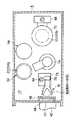
図1は本発明に係る被処理体の処理システムの一例を示す概略構成図、図2は被処理体移載エリア内の各構成部材の配列位置の一例を示す平面図、図3は被処理体の移載アーム機構の一例を示す図である。Hereinafter, a preferred example of a processing system for a target object and a heat treatment method for a target object according to the present invention will be described in detail with reference to the accompanying drawings.
FIG. 1 is a schematic configuration diagram illustrating an example of a processing system for an object to be processed according to the present invention, FIG. 2 is a plan view illustrating an example of an arrangement position of each constituent member in an object transfer area, and FIG. It is a figure which shows an example of the transfer arm mechanism of a body.
まず、図1及び図2に示すように、この被処理体の処理システム2は、全体が区画壁として機能する例えばステンレス等よりなる筐体4に囲まれており、この内部は収容ボックス6を搬送するための収容ボックス搬送エリア8と被処理体である半導体ウエハWを移載する被処理体移載エリア10とに区画壁12により2分されている。尚、ここではウエハWは直径が300mmのウエハを用いるが、これに限定されず、直径が8インチ、6インチのウエハも用いることができる。上記収容ボックス6には、複数枚、例えば25枚のウエハが段部状に支持されて開閉蓋6Aにより密閉状態になされており、内部はN2 ガス等の不活性ガス雰囲気や清浄空気の雰囲気になされている。そして、上記収容ボックス搬送エリア8内には清浄空気のダウンフローが流され、上記被処理体移載エリア10内にはN2 ガス等の不活性ガス雰囲気になされている。尚、このエリア10内に清浄空気を流す場合もある。First, as shown in FIGS. 1 and 2, the processing system 2 for the object to be processed is surrounded by a casing 4 made of, for example, stainless steel, which functions as a partition wall as a whole. It is divided into two by a
この処理システム2は、主に収容ボックス6を処理システム2内に対して搬入搬出させるための搬出入ポート16と、上記収容ボックス6を一時的に貯留するためのストッカ部18と、この収容ボックス6と被処理体ボート20との間で半導体ウエハWを移載する移載ステージ22と、被処理体ボート20に移載されて保持されている半導体ウエハWに対して所定の熱処理を施す処理ユニット24とにより主に構成される。 The processing system 2 mainly includes a loading / unloading
上記搬出入ポート16において、筐体4には常時開放されているボックス搬出入口26が形成されている。尚、このボックス搬出入口26が開閉ドアで開閉可能になされている場合もある。このボックス搬出入口26の外側には、外部より搬送してきた収容ボックス6を載置するための外側載置台28が設けられると共に、このボックス搬出入口26の内側には、上記外側載置台28よりスライド移動されてくる収容ボックス6をその上に載置するための内側載置台30が設置されている。上記外側、或いは内側載置台28、30の上部には、両載置台28、30間をスライド移動可能になされたスライド板32が設けられており、この上に収容ボックス6を載せた状態で移動できるようになっている。 In the carry-in /
一方、収容ボックス搬送エリア8内の上方には、上記ストッカ部18が位置されている。このストッカ部18は、図示例においては例えば2列2段に上記収容ボックス6を一時的に載置して保管する棚段34が並設されている。尚、この棚段34の数量は特に限定されず、実際には更に多く設けられる。 On the other hand, the
上記2つの棚段34間には、昇降エレベータ36が起立させて設けられており、この昇降エレベータ36には、水平方向に前進後退及び旋回可能になされたボックス搬送アーム38が設けられている。従って、このボックス搬送アーム38を屈伸及び昇降させることにより、収容ボックス6をボックス搬送アーム38で保持し、搬出入ポート16とスットカ部18との間で搬送できるようになっている。 A
また、上記移載ステージ22において、両エリア8、10間を区画する区画壁12には、収容ボックス6の開閉蓋6Aよりも僅かに大きくなされた開口40が形成されると共に、この開口40の収容ボックス搬送エリア8側には、載置台42が水平に設けられており、この上に収容ボックス6を載置できるようになっている。また、この載置台42の一側には、この上に載置された収容ボックス6を区画壁12側へ押圧付勢するための水平アクチュエータ44が設けられており、上記収容ボックス6の開閉蓋6Aを、上記開口40に臨ませた状態で収容ボックス6の開口部の開口縁が区画壁12の開口40の開口縁に略気密に接触されることになる。 Further, in the
また、この開口40の被処理体移載エリア10側には、これを開閉する開閉ドア46が横方向へスライド可能に設けられている。また、この開閉ドア46には上記収容ボックス6の開閉蓋6Aを開閉するための蓋開閉機構48が設けられている(図2参照)。そして、収容ボックス搬送エリア8内において、この開口40の近傍に収容ボックス6を待機させるための待機用ボックス搬送アーム50が設置されており、次に処理すべきウエハを収容する収容ボックス6をボックス搬送アーム38から受け取り、待機後にこれを移載ステージ22に置くようになっている。尚、上記待機用ボックス搬送アーム50を設けない場合もあり、この場合には、上記ボックス搬送アーム38により収容ボックス6を移載ステージ22上に設置することになる。 In addition, an opening / closing
一方、上記被処理体移載エリア10内には、ウエハボートの如き被処理体ボート20を載置する2つのボート載置台、すなわち移載用ボート載置台52と待機用ボート載置台54とが設けられている。上記2つのボート載置台52、54の内、この待機用ボート載置台52と上記移載ステージ22との間には、水平方向へ前進後退及び旋回可能になされた移載アーム機構56が設けられており、この移載アーム機構56は昇降エレベータのようなアーム昇降手段58により上下動可能になされている。このアーム昇降手段58として例えばボールネジ等を用いることができる。 On the other hand, in the processing
従って、この移載アーム機構56を屈伸、旋回及び昇降駆動することにより、載置台42上の収容ボックス6と移載用ボート載置台52上の被処理体ボート20との間でウエハWの移載を行なうことができるようになっている。ここでは被処理体ボート20に関しては、複数台、例えば2台の被処理体ボート20A、20Bが設けられており、この2台が交互に用いられる。尚、被処理体ボート20を3台以上設けてもよい。 Accordingly, the
この被処理体ボート20は、例えば石英よりなり、例えば50〜150枚程度のウエハWを所定のピッチで多段に支持できるようになっている。そして、上記移載アーム機構56は、具体的には、図3にも示すように、上記アーム昇降手段58によって昇降されるベース台76を有しており、このベース台76には、スライド移動及び旋回移動可能になされたアーム台78が設けられている。そして、このアーム台78には、その上にウエハWを載置して水平方向へ個別に前進及び後退可能になされた複数本の2股状になされたアーム80が上下に並列させて設けられている。ここでは上記アーム80に関しては、5本のアーム80A、80B、80C、80D、80Eが設けられており、一度に最大5枚のウエハWを移載できるようになっている。 The
そして、上記5本のアーム80A〜80Eの内の一本のアーム、ここでは中央のアーム80Cの先端部には、ウエハWの有無を検出するためのマッピングセンサ82が設けられており、上記収容ボックス6内を縦方向に走査したり、或いは上記被処理体ボート20を縦方向に走査したりすることにより、ウエハWが収容されている位置を検出するようになっている。このマッピングセンサ82は、例えば光送受光器よりなり、その耐熱性はそれ程高くなく、耐熱上限温度は例えば130℃程度である。 A mapping sensor 82 for detecting the presence / absence of the wafer W is provided at one end of the five
また、上記ベース台76には、例えば上記マッピングセンサ82等に関連する電子回路や上記各アーム80A〜80Eの駆動制御用の電子回路などを形成する電子部品84がベース台76のカバー76Aにより保護された状態で搭載されている。上記電子部品84の耐熱上限温度は、上記マッピングセンサ82よりも低く、例えば50℃程度である。更に、この移載アーム機構56には、上記各アーム80A〜80Eやアーム台78等を駆動するための加圧気体を給排するために可撓性のある樹脂製のエアチューブ(図示せず)が配設されている。 Further, on the base table 76, for example,
また、この被処理体移載エリア10の一側の上方には、縦型熱処理炉よりなる処理ユニット24がベース板62により支持されて配置されている。この処理ユニット24は、石英製の円筒体状の処理容器64を有し、その周囲には円筒状の加熱ヒータ66が設けられて、処理容器64内のウエハを加熱し得るようになっている。これにより、一度に多数枚のウエハWに対して成膜や酸化拡散等の所定の熱処理を施すようになっている。 Further, a processing unit 24 composed of a vertical heat treatment furnace is supported above and arranged on one side of the
この場合、処理内容にもよるが、ウエハ温度は例えば最大800〜1000℃程度になる。この処理容器64の下方には、昇降エレベータのようなボート昇降手段68により昇降可能になされたキャップ70が配置されている。このボート昇降手段68として例えばボールネジ等を用いることができる。そして、このキャップ70上に被処理体ボート20を載置してこれを上昇させることにより、この被処理体ボート20を処理容器64の下端開口部よりこの処理容器64内へロードできるようになっている。この時、処理容器64の下端開口部は上記キャップ70により気密に閉じられるようになっている。 In this case, the wafer temperature is, for example, about 800 to 1000 ° C. at maximum, depending on the processing contents. A
また処理容器64の下端開口部の側部には、上記被処理体ボート20をアンロードしてこれを下方向へ降下させた際に、上記下端開口部を閉じるシャッタ72がスライド可能に設けられている。そして、降下されたキャップ70と上記両ボート載置台52、54の近傍には、屈伸及び旋回可能になされたボート移載機構74が設けられており、上記両ボート載置台52、54とキャップ70との間及び両ボート載置台52、54間で被処理体ボート20の移載ができるようになされている。 A
そして、上記被処理体移載エリア10内の上部には、本発明の特徴とする温度測定手段86(図1参照)が設けられており、この被処理体移載エリア10内の雰囲気の温度を検出するようになっている。具体的には、上記温度測定手段86は、熱電対86Aよりなり、この熱電対86Aは、上記移載アーム機構56の上方の天井部、すなわちアーム昇降手段58の上端部の近傍に設けられており、この部分の雰囲気の温度を検出するようになっている。 And the temperature measuring means 86 (refer FIG. 1) which is the characteristics of this invention is provided in the upper part in the said to-be-processed
尚、温度測定手段86として上記熱電対86Aに限定されず、例えばこれに替えて放射温度計等を用いるようにしてもよい。また上記温度測定手段86の設置位置としては、上記した天井部に限定されず、例えば上記移載アーム機構56のウエハ移載時における上死点(移載アーム機構が到達する最上端の位置)の部分に設置するようにしてもよい。 The temperature measuring means 86 is not limited to the
そして、この温度測定手段86の測定値は、例えばコンピュータ等よりなる移載制御部88に入力されており、この移載制御部88は、この測定値に基づいて上記移載アーム機構56の移載動作を制御するようになっている。具体的には、上記移載制御部88は、上記処理ユニット24から上記被処理体ボート20を降下させるアンロードを開始した後に上記温度測定手段86が第1の温度を検出した時以降は、上記ウエハの移載を禁止(不許可)するようにし、上記被処理体ボート20が最下端に到達することにより上記アンロードを完了した後に上記温度測定手段86が上記第1の温度よりも高い第2の温度を検出した時以降は、上記ウエハの移載の禁止(不許可)を解除してウエハの移載が可能となるように制御するようになっており、これにより上記移載アーム機構56が熱的ダメージを受けることを防止するようにしている。 The measured value of the temperature measuring means 86 is input to a
ここで上記ウエハの移載操作を禁止している期間では、上記移載アーム機構56はこの被処理体移載エリア10内で一番温度が低い領域、すなわち、この被処理体移載エリア10内の下部(底部)、例えばボトムポジション(下死点)90(図1参照)に位置させて退避させるようになっている。 Here, during the period during which the wafer transfer operation is prohibited, the
そして、この被処理体移載エリア10内には、清浄空気、又はN2 ガス等の不活性ガスのサイドフローが常時形成されており、この被処理体移載エリア10内を清浄に保つと共に、この雰囲気温度を冷却するようになっている。Then, the
そして、この処理システム2の全体の動作の制御、例えば収容ボックス搬送エリア8内における収容ボックス6の搬入及び搬出操作、被処理体移載エリア10内におけるウエハWの移載操作、被処理体ボート20の移載操作、被処理体ボート20の昇降操作、処理ユニット24における熱処理操作(成膜処理等)等は、例えばコンピュータよりなる装置制御部92により制御される。この場合、上記移載制御部88は、上記装置制御部92の支配下になっている。そして、上記装置制御部92や移載制御部88の制御に必要なプログラム(コンピュータによって読み取り可能)は記憶媒体94に記憶されている。この記憶媒体94としては、例えばフレキシブルディスクやCD(Compact Disc)やハードディスクやフラッシュメモリ等よりなる。 Control of the overall operation of the processing system 2, for example, loading and unloading operations of the
次に、以上のように構成された処理システム2の動作について、図4乃至図7も参照して説明する。図4は1バッチ処理における各工程のタイミングチャートの一例を示す図、図5は移載アーム機構を退避させない時の被処理体移載エリア内における各部の温度変化を示すグラフ、図6は移載アーム機構を退避させた時の被処理体移載エリア内における各部の温度変化を示すグラフ、図7は半導体ウエハに対する搬送を含む熱処理の全工程を示すフローチャートである。 Next, the operation of the processing system 2 configured as described above will be described with reference to FIGS. FIG. 4 is a diagram showing an example of a timing chart of each process in one batch process, FIG. 5 is a graph showing a temperature change of each part in the workpiece transfer area when the transfer arm mechanism is not retracted, and FIG. FIG. 7 is a flowchart showing all steps of the heat treatment including transfer to the semiconductor wafer. FIG. 7 is a graph showing the temperature change of each part in the workpiece transfer area when the mounting arm mechanism is retracted.
まず、被処理体移載エリア10内は、ウエハ表面への自然酸化膜の付着を防止するために不活性ガス、例えばN2 ガスのサイドフローが形成されてN2 雰囲気になされている。また、収容ボックス搬送エリア8内は、清浄空気のダウンフローが形成されて清浄空気の雰囲気に維持されている。First, in the
最初に、半導体ウエハWの全体的な流れについて説明すると、収容ボックス搬送エリア8側において外部より搬送されてきた収容ボックス6は、その開閉蓋6Aをボックス搬出入口26側に向けて外側載置台28上に載置される。そして、収容ボックス6が載置されている外側載置台28上のスライド板32を前進させることによって、これを内側載置台30上に移送する。 First, the overall flow of the semiconductor wafer W will be described. The
次に、ボックス搬送アーム38を駆動することにより、内側載置台30上に設置されている収容ボックス6を取りに行ってこれを保持し、更に昇降エレベータ36を駆動することによって、この収容ボックス6を上方のストッカ部18の棚段34の所定の位置まで搬送して設置し、これを一時的に保管する。これと同時に、すでに棚段34に一時貯留されており、処理対象となったウエハを収容する収容ボックス6をこのボックス搬送アーム38により取りに行き、上述のように昇降エレベータ36を駆動してこれを降下させる。 Next, by driving the
そして、移載ステージ22の載置台42が空の場合には、この収容ボックス6を移載ステージ22の載置台42上に移載する。また、載置台42上に別の収容ボックス6がすでにセットされている場合には、ボックス搬送アーム38上の収容ボックス6を待機用ボックス搬送アーム50で把持し、これを開口40の近傍まで搬送して待機させる。そして、載置台42上の収容ボックス6の開閉蓋6Aは、開閉ドア46側に向けられており、しかも、載置台42の一側に設けた水平アクチュエータ44により、収容ボックス6は押圧付勢されて載置台42上にて固定されている。 When the mounting table 42 of the
この状態で、蓋開閉機構48を駆動することにより、開口40の開閉ドア46と収容ボックス6の開閉蓋6Aとを取り外し、これらを例えば水平方向へスライド移動させて退避させる。そして、移載アーム機構56及びアーム昇降手段58を駆動することにより、収容ボックス6内に収容されていたウエハWを、ここでは5枚ずつ取り出し、これを移載用ボート載置台52上に設置されている被処理体ボート20に移載する。 In this state, by driving the lid opening /
この場合、被処理体ボート20のウエハ収容枚数が100枚で、且つ収容ボックス6内のウエハ収容枚数が25枚ならば、4つの収容ボックス6内からウエハが取り出されて移載され、1バッチの処理が行われることになる。 In this case, if the number of wafers stored in the
上記被処理体ボート20へのウエハWの移載が完了したならば、次に、ボート移載機構74を駆動して、この移載用ボート載置台52上の被処理体ボート20を最下端へ降下されているキャップ70上に載置する。ここで、熱処理が完了してアンロードされたウエハを収容する被処理体ボート20が上記キャップ70上にある場合には、ボート移載機構74を用いてこの被処理体ボート20を予め待機用ボート載置台54上へ移しておく。 When the transfer of the wafer W to the
そして、この未処理のウエハを収容する被処理体ボート20の移載が完了したならば、ボート昇降手段68を駆動させて、被処理体ボート20と、これを載置したキャップ70を一体的に上昇させ、この被処理体ボート20を処理ユニット24の処理容器64内へ、この下端開口部より導入してロードする。そして、このキャップ70によって処理容器64の下端開口部を密閉し、この状態で処理ユニット24内でウエハWに対して所定の熱処理、例えば成膜処理や酸化拡散処理等を行なう。この場合、熱処理の態様にもよるが、ウエハWの温度は800〜1000℃の高温に達する。 When the transfer of the
このようにして、所定の時間の熱処理が終了したならば、前述したと逆の操作を行なって、処理済みのウエハWを取り出す。すなわち、アンロードを開始することより被処理体ボート20を処理容器64内から降下させてアンロードを完了する。この際、アンロードを開始して被処理体ボート20の降下を開始すると、被処理体移載エリア10内の雰囲気は高温状態になるので、耐熱性に劣る移載アーム機構56を後述するように下方へ退避させる。そして、このアンロードされた被処理体ボート20は、ボート移載機構74により、待機用ボート載置台54を経由して、或いはこれを経由することなく直接的に移載用ボート載置台52上へ移載される。この間に上記処理済みのウエハWは、ある程度冷却されている。 In this way, when the heat treatment for a predetermined time is completed, the reverse operation as described above is performed, and the processed wafer W is taken out. That is, by starting unloading, the to-
そして、移載アーム機構56とアーム昇降手段58を用いて処理済みのウエハWを被処理体ボート20から移載ステージ22の載置台42上の空の収容ボックス6内に移載する。この収容ボックス6内への処理済みウエハWの移載が完了したならば、開閉ドア46を開口40へ装着し、更に蓋開閉機構48を駆動して、これに保持していた開閉蓋6Aを収容ボックス6側へ装着する。 Then, the processed wafer W is transferred from the
次に、収容ボックス搬送エリア8内のボックス搬送アーム38を駆動し、この収容ボックス6を一時的にストッカ部18へ貯留し、或いは貯留することなくボックス搬出入口26を介して処理システム2の外へ搬送することになる。このボックス搬送アーム38が処理済みのウエハを収容した収容ボックス6を搬送している間、すでに空の収容ボックス6を把持して待機していた待機用ボックス搬送アーム50は、この空の収容ボックス6を載置台42上にセットし、処理済みのウエハの収容ボックス6内への収容が開始されることになる。この場合、例えば4つの空の収容ボックス6が用いられることになる。そして、これにより、1バッチのウエハの処理が完了する。以下、同様な操作が繰り返される。尚、上記した収容ボックス6の流れは単に一例を示したに過ぎず、これに限定されないのは勿論である。 Next, the
ここで、高温状態の上記被処理体ボート20を高温状態の処理容器64内から降下させるアンロードを行う場合には、前述したように耐熱性が高くない移載アーム機構56が熱的ダメージを受けることを防止するために、移載アーム機構56の移載動作を禁止し、これを下方へ降下させて図1中のボトムポジション90に位置させて退避させるようにしている。このように、移載アーム機構56を下方へ退避させる理由は、この被処理体移載エリア10内は、高温状態の被処理体ボート20やウエハWからの放熱により、更には内部雰囲気の対流により、上部側の雰囲気温度がかなり上昇するのに対して、下部側の雰囲気温度の上昇は少ないからである。 Here, when unloading is performed to lower the
そして、従来の処理システムにあっては、移載アーム機構の移載禁止の期間を、アンロードの開始から被処理体ボート20が最下端まで到達してアンロードが完了した後に被処理体移載エリア10内の雰囲気が経験的に十分に冷却されるまでの長い時間、例えば10分程度を固定的に設定し、この長い時間に亘ってウエハの移載を禁止するようにしていた。この結果、前述したように、ウエハの移載操作が遅延してスループットが低下する場合が発生していた。 In the conventional processing system, the transfer prohibition period of the transfer arm mechanism is set so that the
これに対して、本発明では、被処理体移載エリア10内の天井部に設けた例えば熱電対86Aよりなる温度測定手段86によりこのエリア10内の雰囲気温度が検出されており、移載アーム機構56は被処理体ボート20のアンロードが開始したら直ちに退避されるのではなく、アンロード開始後に上記温度測定手段86が第1の温度を検出した時に退避させるようにし、そして、アンロードが完了した後に上記温度測定手段86が上記第1の温度よりも高い第2の温度を検出した時に移載禁止を解除するようにしている。換言すれば、上記温度測定手段86が第1の温度を検出した時から、雰囲気温度がピークになって、その後、この温度が降下して第2の温度を検出するまでの間、上記ウエハの移載操作が禁止されることになる。 On the other hand, in the present invention, the ambient temperature in the
これにより、移載アーム機構56に熱的ダメージを与えることなく移載禁止の期間を最少限にでき、これによって移載効率を上げてスループットを向上させることが可能となる。尚、上記した制御は、この処理システム2の全体の動作を制御する装置制御部92の支配下にある移載制御部88によって行われる。 As a result, the transfer prohibition period can be minimized without causing thermal damage to the
上記した熱処理の各工程をバッチ毎にタイミングチャートとしてその一例を表すと図4に示すようになる。ここでは、n(正の整数)番目のバッチ処理とn+1番目のバッチ処理とのタイミングチャートの一例を示している。 FIG. 4 shows an example of each process of the heat treatment described above as a timing chart for each batch. Here, an example of a timing chart of the n (positive integer) th batch process and the (n + 1) th batch process is shown.
ここでは図示するように、各バッチ処理の主な工程を示すと、各バッチ処理では、それぞれウエハ移載工程、被処理体ボートの交換工程、ボートのロード工程、熱処理工程、ボートアンロード程度、ボート冷却工程、ボート交換工程、ウエハ移載工程(処理済み)のように順に実行されて行く。例えばn番目のバッチ処理中にn+1番目のバッチ処理の要求が装置制御部92からなされると、被処理体移載エリア10内ではn+1番目のバッチ処理用の未処理のウエハを被処理体ボート20へ移載するウエハ移載操作が開始され、例えば前述したように全部で4つの収容ボックス6内の100枚のウエハWの移載が収容ボックス6を取り替えつつ行われる。 Here, as shown in the figure, the main processes of each batch process are shown. In each batch process, a wafer transfer process, a process boat replacement process, a boat loading process, a heat treatment process, a boat unloading degree, The boat cooling process, the boat exchange process, and the wafer transfer process (processed) are executed in order. For example, when a request for the (n + 1) th batch process is made from the
そして、このウエハ移載の途中で、n番目の熱処理操作が完了して被処理体ボート20のアンロードが開始されてもウエハ移載は継続して行われており、その後に温度測定手段86が第1の温度を検出すると直ちにウエハ移載は禁止され、ウエハ移載操作は中断されることになる。 In the middle of the wafer transfer, even if the n-th heat treatment operation is completed and the unloading of the
このウエハ移載が禁止の間は、前述したように移載アーム機構56は下部のボトムポジション90に位置されて退避された状態となっている。そして、その後に、被処理体ボート20のアンロードが完了した後に上記温度測定手段86が第2の温度を検出すると直ちにウエハ移載の禁止が解除されることになり、ここでは中断していたウエハの移載操作が再開されることになる。これにより、ウエハ移載の禁止期間は、従来の処理システムの場合は26分程度あったが、本発明の処理システムの場合には、20分以内までに短縮化することができる。従って、その分、ウエハの移載操作を迅速に、且つ効率的に行うことができるので、スループットを向上させることができる。 While this wafer transfer is prohibited, the
尚、図4に示す場合には、n+1番目のバッチ処理に対してウエハの移載操作がボートのアンロードによって2つに分断されているが、n+1番目のバッチ処理に関する処理ウエハの要求のタイミングが異なれば、例えばもう少し早目に出ていれば、上記ウエハの移載操作が分断されることなく連続的に行われるのは勿論である。 In the case shown in FIG. 4, the wafer transfer operation for the (n + 1) th batch process is divided into two by the unloading of the boat. Of course, the wafer transfer operation is performed continuously without being divided, for example, if it appears a little earlier.
ここで上記被処理体移載エリア10内の温度変化を実際に測定したので、その結果を図5及び図6を参照して説明する。図5は移載アーム機構を退避させない時の被処理体移載エリア内における各部の温度変化を示すグラフ、図6は移載アーム機構を退避させた時の被処理体移載エリア内における各部の温度変化を示すグラフである。ここでは、熱電対を3つ用い、1つ目を温度測定手段86の設置位置に対応する天井部に設け、2つ目を移載アーム機構56の中央のアーム80Cの先端部のマッピングセンサ82の位置に設け、3つ目をベース台76のカバー76Aで覆われた電子部品84(図3参照)が設けられている。 Here, since the temperature change in the said to-be-processed
そして、曲線A1は天井部の熱電対の測定値を示し、曲線A2はマッピングセンサに設けた熱電対の測定値を示し、曲線A3は電子部品に設けた熱電対の測定値を示す。ここでは被処理体移載エリア10内にサイドフローが形成されており、被処理体ボート20が780℃に加熱された状態でアンロードを行った時の温度が示されている。また、アンロード期間は、16分程度に設定してある。 Curve A1 indicates the measured value of the thermocouple at the ceiling, curve A2 indicates the measured value of the thermocouple provided in the mapping sensor, and curve A3 indicates the measured value of the thermocouple provided in the electronic component. Here, a side flow is formed in the
まず、図5に示すように、アンロードが開始されても移載アーム機構56を退避させないでウエハ移載操作の動きを継続して行っている場合には、各曲線A1〜A3は、アンロード開始後は暫くは温度上昇が見られず、そして、3分程度経過した時に温度上昇が始まる。この場合、天井部の熱電対の温度を示す曲線A1はかなり急激に温度上昇が生じ、途中に若干の温度の上下変動はあるものの、アンロード完了まで温度上昇は継続してピーク温度として170℃程度まで達する。そして、アンロード完了後は温度は急激に低下している。 First, as shown in FIG. 5, when the movement of the wafer transfer operation is continuously performed without retracting the
またマッピングセンサの熱電対の温度を示す曲線A2は、曲線A1よりは少し緩やかな角度で温度上昇が生じ、アンロード完了まで温度上昇は継続してピーク温度として120℃程度まで達する。そして、アンロード完了後は温度は緩やかに低下している。更に、電子部品の熱電対の温度を示す曲線A3は、曲線A2よりも更に緩やかな角度で温度上昇が生じ、アンロード完了まで温度上昇は継続してピーク温度として90℃程度まで達する。そして、アンロード完了後は温度は緩やかに低下している。 The curve A2 indicating the temperature of the thermocouple of the mapping sensor rises at a slightly slower angle than the curve A1, and the temperature rise continues until the unloading is completed and reaches a peak temperature of about 120 ° C. And after the unloading is completed, the temperature gradually decreases. Further, the curve A3 indicating the temperature of the thermocouple of the electronic component rises at a more gentle angle than the curve A2, and the temperature rise continues until the unloading is completed and reaches about 90 ° C. as a peak temperature. And after the unloading is completed, the temperature gradually decreases.
以上の結果から、被処理体ボート20のアンロードが開始されても、直ちに移載アーム機構56を退避させる必要はなく、その後、3分間程度はウエハの移載操作を継続して行っても、この移載アーム機構56は熱的ダメージを受けないことが理解できる。 From the above results, even if the unloading of the
ここで、上記マッピングセンサ82の耐熱上限温度は例えば130℃程度であるのに対して、カバー76Aで覆われた上記電子部品84の耐熱上限温度は上記マッピングセンサ82よりも低くて例えば50℃程度なので、移載アーム機構56が熱的ダメージを受けることなくウエハ移載の操作を効率的に行うために、上記第1の温度として電子部品84の耐熱上限温度、すなわち50℃を設定し、上記第2の温度として上記マッピングセンサ82の耐熱上限温度、すなわち130℃を設定する。 Here, the heat-resistant upper limit temperature of the mapping sensor 82 is, for example, about 130 ° C., whereas the heat-resistant upper limit temperature of the
この理由は、ウエハの移載操作を禁止して退避指示を出す時は、被処理体移載エリア10内の雰囲気温度、特に天井部の雰囲気温度は急激な上昇傾向にあり、且つ底部の雰囲気温度も緩やかではあるが上昇傾向にあるので、すなわち換言すれば熱的に厳しい環境に移行しつつある段階なので、ここでは最も熱的に弱い電子部品84の耐熱上限温度を退避を行うトリガとする。 This is because when the wafer transfer operation is prohibited and a retraction instruction is issued, the ambient temperature in the
これに対して、ウエハの移載の禁止を解除する退避解除指示を出す時は、被処理体移載エリア10内の雰囲気温度、特に天井部の雰囲気温度は急激な下降傾向にあり、且つ底部の雰囲気温度も緩やかではあるが下降傾向にあるので、すなわち換言すれば熱的に緩やかな環境に移行しつつある段階なので、ここでは雰囲気に直接的に晒されるマッピングセンサ82の耐熱上限温度を退避を行うトリガとする。この場合、熱的に弱い電子部品84が熱的ダメージを受ける恐れが生ずるが、この電子部品84は上述のようにカバー76によって保護されているので、急激な温度上昇が生ずることはなく(図5中の曲線A3参照)、熱的ダメージを受けることはない。 On the other hand, when issuing an evacuation release instruction for canceling the prohibition of wafer transfer, the ambient temperature in the
以上のような概念のもとに、温度測定手段86が第1の温度(50℃)を検出した時にウエハの移載操作を禁止して移載アーム機構56の退避指示を出し、アンロード完了後に第2の温度(130℃)を検出した時に退避解除の指示を出した時の温度変化を図6に示す。 Based on the above concept, when the temperature measuring means 86 detects the first temperature (50 ° C.), the wafer transfer operation is prohibited and a retraction instruction for the
図6に示すように、退避指示により移載アーム機構56は下方のボトムポジション90に位置されるので、曲線A2、A3に示すように、マッピングセンサ82や電子部品84の温度上昇は抑制されて、これらが熱的ダメージを受けることがないことを理解することができる。この場合、ウエハ移載操作の禁止期間t1は、19分程度なので、従来の処理システムの場合の26分よりも大幅に短縮化することができ、従って、その分ウエハ移載効率を向上させることができる。 As shown in FIG. 6, the
次に、上記した一連の動作を図7に示すフローチャートも参照して説明する。
まず、装置制御部9においてウエハ処理の要求が有るか否かを判断する(S1)。この場合、例えばストッカ部18に未処理のウエハを収容する収容ボックス6が貯留されていたり、或いは外部より未処理のウエハを収容する収容ボックス6が搬送されてくれば、その順序に従って、ウエハ処理の要求がなされていく。Next, the series of operations described above will be described with reference to the flowchart shown in FIG.
First, the
ここでウエハ処理の要求があった場合には(S1のYES)、前述したように、移載ステージ22の載置台42上に収容ボックス6を設定し、このウエハWを被処理体エリア10内の待機中の被処理体ボート20へ移載する(S2)。そして、例えば収容ボックス6の4個分の100枚のウエハWの移載が完了したならば、この被処理体ボート20をボート移載機構74によりボート昇降手段68へ移載(ボート交換)する(S3)。 If there is a request for wafer processing (YES in S1), the
上記被処理体ボート20の移載を行ったならば、ボート昇降手段68によりこの被処理体ボート20を上昇させてローディング(ロード)し、処理ユニット24の処理容器64内へ被処理体ボート20収容し、ウエハWに対する熱処理を開始する(S4)。 When the
次に、このウエハWの熱処理中にウエハ処理の要求が有るか否かが判断され(S5)、ウエハ処理の要求が有った場合には(S5のYES)、未処理のウエハを収容する収容ボックス6内のウエハWを、上記S2のステップと同様に待機中の被処理体ボート20へ移載する移載操作を開始する(S6)。尚、被処理体ボート20は、ここでは2台、すなわち被処理体ボート20A、20Bを有しており、これらが交互に用いられることになる。 Next, it is determined whether or not there is a request for wafer processing during the heat treatment of the wafer W (S5). If there is a request for wafer processing (YES in S5), an unprocessed wafer is accommodated. A transfer operation for transferring the wafer W in the
そして、上記ウエハ処理の要求がない場合(S5のNO)や上記ウエハの移載を行っている時に被処理体ボート20のアンロードの開始指示が有るか否かが判断される(S7)。尚、ウエハの上記熱処理操作が完了すると装置制御部92はアンロードの開始指示をすることになる。 Then, when there is no request for the wafer processing (NO in S5) or when the wafer is being transferred, it is determined whether there is an instruction to start unloading the workpiece boat 20 (S7). When the heat treatment operation for the wafer is completed, the
上記判断の結果、アンロードの開始指示が無い場合には(S7のNO)、上記S5のステップに戻る。そして、この判断の結果、アンロードの開始指示が有った場合には(S7のYES)、装置制御部92は例えば780℃程度の高温状態の被処理体ボート20を降下させてアンロードを開始する。この開始後、暫くして被処理体移載エリア10内の雰囲気温度は、図5及び図6で説明したように上昇してくることになる。 If the result of the determination is that there is no unload start instruction (NO in S7), the process returns to step S5. If the result of this determination is that there is an unload start instruction (YES in S7), the
また、上記アンロードの開始指示のあったことは、アンロード開始信号によって上記装置制御部92から移載制御部88へ通知されることになる。この通知が入ると、この移載制御部88は、被処理体移載エリア10内の天井部に設けた温度測定手段86が第1の温度(例えば50℃)を検出したか否かの判断を開始する(S8のNO)。すなわち、第1の判断工程を行う。そして、この第1の判断工程において第1の温度(例えば50℃)を検出した場合には(S8のYES)、上記装置制御部88はウエハの移載操作を禁止乃至不許可とし(S9)、ウエハ移載中の場合には(S10のYES)、ウエハの移載操作を中断し(S11)、移載アーム機構56を下部に位置させて退避させる(S12)。また、ウエハの移載中でない場合も(S10のNO)、同様に移載アーム機構56を下部に位置させて退避させる(S12)。これにより、上記移載アーム機構56が熱的ダメージを受けることを防止する。 Further, the fact that there has been an instruction to start unloading is notified from the
そして、このように移載アーム機構56を退避させた状態で、上記移載制御部88はアンロードの完了を示すアンロード完了信号が装置制御部92側から通知されたか否かを判断し、アンロード完了信号の通知を待つ(S13)。そして、アンロード完了信号を移載制御部88が受けると、この移載制御部88は上記温度測定手段86が第2の温度(例えば130℃)を検出したか否かの判断を開始する(S14のNO)。すなわち、第2の判断工程を行う。 Then, with the
そして、この第2の判断工程において、第2の温度(例えば130℃)を検出したならば(S14のYES)、ウエハ移載操作の禁止(不許可)を解除する(S15)。この解除により、ウエハの移載操作が中断されていた場合、或いはウエハ処理の要求があった場合には(S16のYES)、S2のステップへ戻って、ウエハの移載操作が再開、或いは開始されることになる。また、ウエハの移載操作の中断やウエハ処理の要求が無い場合には(S16のNO)、処理が終了することになる。 If the second temperature (for example, 130 ° C.) is detected in the second determination step (YES in S14), the prohibition (non-permission) of the wafer transfer operation is canceled (S15). If the wafer transfer operation is interrupted by this release or if there is a request for wafer processing (YES in S16), the process returns to step S2 to resume or start the wafer transfer operation. Will be. If there is no interruption of the wafer transfer operation or a request for wafer processing (NO in S16), the processing ends.
このように、本発明によれば、被処理体ボート20に対して被処理体である半導体ウエハWを移載するための被処理体移載エリア10内の上部に温度測定手段86を設け、この温度測定手段86の測定値に基づいて移載アーム機構56の移載動作を制御するようにしたので、移載アーム機構56が熱的ダメージを受けることを防止しつつ、移載アーム機構56が退避している時間を最小限にして被処理体の移載操作を効率的に行うようにし、もってスループットを向上させることができる。 As described above, according to the present invention, the temperature measuring means 86 is provided in the upper portion in the
尚、上記実施例における第1の温度及び第2の温度は、単に一例を示したに過ぎず、対応する各部材の耐熱上限温度が変われば、これに対応して第1の温度及び第2の温度の各値も変化させるのは勿論である。
また、ここでは温度測定手段86を一個設けた場合を例にとって説明したが、これに限定されず、複数個設けるようにしてもよく、この際は上記移載アーム機構56の上方に必ず1つは設けるのが好ましい。そして、この温度測定手段86を複数個設けた場合には、最も高い雰囲気温度を検出した温度測定手段86の測定値を有効なものとして扱えばよい。Note that the first temperature and the second temperature in the above embodiment are merely examples, and if the heat-resistant upper limit temperature of each corresponding member changes, the first temperature and the second temperature corresponding to this change. Of course, each value of the temperature is also changed.
Further, here, the case where one temperature measuring means 86 is provided has been described as an example. However, the present invention is not limited to this, and a plurality of temperature measuring means 86 may be provided. Is preferably provided. When a plurality of temperature measuring means 86 are provided, the measured value of the temperature measuring means 86 that detects the highest ambient temperature may be handled as an effective one.
また、ここでは温度測定手段86を被処理体移載エリア10内の上部として天井部に設けた場合を例にとって説明したが、これに限定されず、移載アーム機構56がウエハ移載操作の際に到達する最上部(上死点)の位置に設けるようにしてもよい。
更に、上記実施例では、被処理体移載エリア10内の上部に温度測定手段86を設けたが、これに加えて動作の安全のために移載アーム機構56にも他の温度測定手段を設けるようにしてもよい。具体的には、例えば熱電対よりなる他の温度測定手段を移載アーム機構56のマッピングセンサ82や電子部品84等に設けるようにして、監視すべき対象物の温度を直接的に監視し、監視対象物の耐熱上限温度を検出した時に移載アーム機構56を退避させるようにする。これによれば、天井部の温度測定手段が故障等しても動作の安全性を高めることができる。
また、ここでは不活性ガスとしてN2 ガスを用いた場合を例にとって説明したが、これに限定されず、Arガス、Heガス等の希ガスを用いてもよい。Here, the case where the temperature measuring means 86 is provided on the ceiling as the upper part in the
Further, in the above embodiment, the temperature measuring means 86 is provided in the upper part in the
Although the case where N2 gas is used as an inert gas has been described as an example here, the present invention is not limited to this, and a rare gas such as Ar gas or He gas may be used.
また、ここでは処理システム2として、被処理体移載エリア10の前段に収容ボックス搬送エリア8を設けた場合について説明したが、これに限定されず、収容ボックス搬送エリア8を設けないで、この部分をクリーンルーム内の作業領域とし、オペレータが収容ボックス6を直接的に移載ステージ22の載置台42上に載置するような構造の処理システムとしてもよい。
また、ここでは被処理体として半導体ウエハを例にとって説明したが、これに限定されず、ガラス基板、LCD基板、セラミック基板等にも本発明を適用することができる。Although the case where the storage box transport area 8 is provided in the preceding stage of the
Although the semiconductor wafer is described as an example of the object to be processed here, the present invention is not limited thereto, and the present invention can be applied to a glass substrate, an LCD substrate, a ceramic substrate, and the like.
2 被処理体の処理システム
4 筐体(区画壁)
6 収容ボックス
6A 開閉蓋
8 収容ボックス搬送エリア
10 被処理体移載エリア
16 搬出入ポート
20 被処理体ボート
22 移載ステージ
24 処理ユニット
52 移載用ボート載置台
54 待機用ボート載置台
56 移載アーム機構
58 アーム昇降手段
64 処理容器
66 加熱ヒータ
68 ボート昇降手段
74 ボート移載機構
76 ベース台
76A カバー
78 アーム台
80,80A〜80E アーム
82 マッピングセンサ
84 電子部品
86 温度測定手段
86A 熱電対
88 移載制御部
90 ボトムポジション
92 装置制御部
94 記憶媒体
W 半導体ウエハ(被処理体)2 Processing system for object 4 Case (partition wall)
6
Claims (10)
Translated fromJapanese前記被処理体に対して熱処理を施すための縦型の処理ユニットと、
前記処理ユニットの下方に設けられて周囲が区画壁により区画された被処理体移載エリアと、
前記被処理体を複数段に亘って保持する複数の被処理体ボートと、
前記被処理体ボートを昇降させて前記処理ユニット内へロード及びアンロードするボート昇降手段と、
前記被処理体の移載時に前記被処理体ボートを載置する移載用ボート載置台と、
前記区画壁に設けられた移載ステージに設置した前記収容ボックスと前記移載用ボート載置台上に載置された被処理体ボートとの間で前記被処理体を移載するための移載アーム機構と、
前記移載アーム機構を昇降させるアーム昇降手段と、
前記被処理体ボートを前記移載用ボート載置台と前記ボート昇降手段との間で移載するボート移載機構と、
熱処理が施された前記被処理体がアンロードされた前記被処理体移載エリア内の雰囲気温度を検出するために前記被処理体移載エリア内の上部に設けられた温度測定手段と、
前記温度測定手段の測定値に基づいて前記移載アーム機構の移載動作を制御し、前記処理ユニットから前記被処理体ボートを降下させるアンロードを開始した後に前記温度測定手段が第1の温度を検出した時以降は前記被処理体の移載を禁止して前記移載アーム機構を前記被処理体移載エリア内の下部に位置させて退避させるようにし、前記アンロードを完了した後に前記温度測定手段が前記第1の温度よりも高い第2の温度を検出した時以降は前記被処理体の移載の禁止を解除するように動作させる移載制御部と、
を備えたことを特徴とする被処理体の処理システム。In the processing system of the object to be processed, the object to be processed is subjected to heat treatment by taking out the object to be processed from a storage box for storing a plurality of objects to be processed.
A vertical processing unit for performing heat treatment on the object to be processed;
An object transfer area provided below the processing unit and surrounded by a partition wall;
A plurality of processing object boats holding the processing object over a plurality of stages;
Boat elevating means for elevating and lowering the object boat to be loaded and unloaded into the processing unit;
A loading boat mounting table for mounting the processing object boat when the processing object is transferred;
Transfer for transferring the object to be processed between the storage box installed on the transfer stage provided on the partition wall and the object boat mounted on the transfer boat mounting table. An arm mechanism;
Arm lifting means for lifting and lowering the transfer arm mechanism;
A boat transfer mechanism for transferring the processing object boat between the transfer boat mounting table and the boat elevating means;
A temperature measuring means provided at an upper part in the workpiece transfer area for detecting an atmospheric temperature in the workpiece transfer area where the workpiece subjected to heat treatment is unloaded;
The temperature measuring means controls the transfer operation of the transfer arm mechanism based on the measurement value of the temperature measuring means, and the temperature measuring meansstarts the unloading to lower theobject boat from the processing unit. After the detection is detected, the transfer of the object to be processed is prohibited, the transfer arm mechanism is positioned at the lower part in the object transfer area, and the unload is completed after the unloading is completed. A transfer control unitthat operates to release the prohibition of transfer of the object to be processed after the temperature measuring means detects a second temperature higher than the first temperature; and
A processing system for an object to be processed.
複数枚の被処理体を保持している被処理体ボートを処理ユニット内へロードして前記被処理体に対して熱処理を施し、熱処理を施したならば前記被処理体ボートをアンロードするようにした熱処理工程と、
移載アーム機構を用いて収容ボックスから前記被処理体ボートとは異なる被処理体ボートに対して被処理体を移載する移載工程と、
被処理体移載エリア内の上部の雰囲気の温度を温度測定手段によって測定する温度測定工程と、
前記処理ユニットから前記被処理体ボートを降下させるアンロードを開始した後に前記温度測定手段が第1の温度を検出した時以降は前記被処理体の移載を禁止して前記移載アーム機構を前記被処理体移載エリア内の下部に位置させて退避させる第1の判断工程と、
前記アンロードを完了した後に前記温度測定手段が前記第1の温度よりも高い第2の温度を検出した時以降は前記被処理体の移載の禁止を解除する第2の判断工程と、
を有することを特徴とする被処理体の熱処理方法。In the heat treatment method of applying a heat treatment to the object to be processed using the processing system of the object to be processed according to any oneof claims 1乃Itaru 6,
A processing object boat holding a plurality of objects to be processed is loaded into the processing unit, the heat processing object is subjected to heat treatment, and if the heat treatment is performed, the object boat is unloaded. A heat treatment process,
A transfer step of transferring the object to be processed from the storage box to the object boat different from the object boat by using the transfer arm mechanism;
A temperature measuring step of measuring the temperature of the upper atmosphere in the workpiece transfer area by a temperature measuring means;
After the start of unloading to lower the object boat from the processing unit, when the temperature measuring means detects the first temperature, the transfer arm mechanism is prohibited by prohibiting the object to be transferred. A first determination step ofretracting the object to be processed by being located at a lower part in the transfer area ;
A second determination stepfor canceling the prohibition of transfer of the object to be processed after the temperature measuring means detects a second temperature higher than the first temperature after completing the unloading ;
A heat treatment method for an object to be processed, comprising:
Priority Applications (5)
| Application Number | Priority Date | Filing Date | Title |
|---|---|---|---|
| JP2007259690AJP5050761B2 (en) | 2007-10-03 | 2007-10-03 | Processing system for object to be processed and heat treatment method for object to be processed |
| CN200810167408.2ACN101404243B (en) | 2007-10-03 | 2008-09-26 | Processing system for process object and thermal processing method for process object |
| US12/285,320US8231381B2 (en) | 2007-10-03 | 2008-10-01 | Processing system for process object and thermal processing method for process object |
| TW097137991ATWI445116B (en) | 2007-10-03 | 2008-10-02 | Processing system for process object and thermal processing method for process object |
| KR1020080097029AKR101194505B1 (en) | 2007-10-03 | 2008-10-02 | Processing system of object to be processed, heat processing method of object to be processed and storage medium |
Applications Claiming Priority (1)
| Application Number | Priority Date | Filing Date | Title |
|---|---|---|---|
| JP2007259690AJP5050761B2 (en) | 2007-10-03 | 2007-10-03 | Processing system for object to be processed and heat treatment method for object to be processed |
Publications (2)
| Publication Number | Publication Date |
|---|---|
| JP2009088438A JP2009088438A (en) | 2009-04-23 |
| JP5050761B2true JP5050761B2 (en) | 2012-10-17 |
Family
ID=40523570
Family Applications (1)
| Application Number | Title | Priority Date | Filing Date |
|---|---|---|---|
| JP2007259690AExpired - Fee RelatedJP5050761B2 (en) | 2007-10-03 | 2007-10-03 | Processing system for object to be processed and heat treatment method for object to be processed |
Country Status (5)
| Country | Link |
|---|---|
| US (1) | US8231381B2 (en) |
| JP (1) | JP5050761B2 (en) |
| KR (1) | KR101194505B1 (en) |
| CN (1) | CN101404243B (en) |
| TW (1) | TWI445116B (en) |
Families Citing this family (10)
| Publication number | Priority date | Publication date | Assignee | Title |
|---|---|---|---|---|
| JP2011035103A (en)* | 2009-07-31 | 2011-02-17 | Tokyo Electron Ltd | Carrier device and processing system |
| JP5625981B2 (en)* | 2011-02-10 | 2014-11-19 | 東京エレクトロン株式会社 | Heat treatment apparatus and heat treatment method |
| JP5617708B2 (en)* | 2011-03-16 | 2014-11-05 | 東京エレクトロン株式会社 | Lid opening / closing device |
| JP5614352B2 (en)* | 2011-03-29 | 2014-10-29 | 東京エレクトロン株式会社 | Loading unit and processing system |
| CN103077909B (en)* | 2012-12-20 | 2016-12-28 | 上海华虹宏力半导体制造有限公司 | The transporter of furnace tube device and transfer approach |
| US10023385B2 (en)* | 2013-11-12 | 2018-07-17 | Daifuku Co., Ltd. | Article storage facility |
| JP6211938B2 (en)* | 2014-01-27 | 2017-10-11 | 東京エレクトロン株式会社 | Substrate heat treatment apparatus and method for installing substrate heat treatment apparatus |
| US9901020B2 (en)* | 2014-10-16 | 2018-02-20 | Fuji Machine Mfg. Co., Ltd. | Nozzle managing system |
| JP6137226B2 (en)* | 2015-03-10 | 2017-05-31 | 村田機械株式会社 | Lifting conveyor |
| US10978322B2 (en)* | 2017-08-30 | 2021-04-13 | Tokyo Electron Limited | Transfer device, substrate processing apparatus, and transfer method |
Family Cites Families (19)
| Publication number | Priority date | Publication date | Assignee | Title |
|---|---|---|---|---|
| US5221201A (en)* | 1990-07-27 | 1993-06-22 | Tokyo Electron Sagami Limited | Vertical heat treatment apparatus |
| US5447294A (en)* | 1993-01-21 | 1995-09-05 | Tokyo Electron Limited | Vertical type heat treatment system |
| JP3218488B2 (en)* | 1993-03-16 | 2001-10-15 | 東京エレクトロン株式会社 | Processing equipment |
| US5527390A (en)* | 1993-03-19 | 1996-06-18 | Tokyo Electron Kabushiki | Treatment system including a plurality of treatment apparatus |
| KR100221983B1 (en)* | 1993-04-13 | 1999-09-15 | 히가시 데쓰로 | A treating apparatus for semiconductor process |
| EP0735573B1 (en) | 1995-03-28 | 2004-09-08 | BROOKS Automation GmbH | Loading and unloading station for semiconductor treatment installations |
| US5829969A (en)* | 1996-04-19 | 1998-11-03 | Tokyo Electron Ltd. | Vertical heat treating apparatus |
| JP3657695B2 (en) | 1996-05-13 | 2005-06-08 | 東京エレクトロン株式会社 | Substrate transfer equipment |
| JP3656701B2 (en) | 1998-03-23 | 2005-06-08 | 東京エレクトロン株式会社 | Processing equipment |
| TW501194B (en) | 2000-08-23 | 2002-09-01 | Tokyo Electron Ltd | Processing system for object to be processed |
| JP3941359B2 (en)* | 2000-08-23 | 2007-07-04 | 東京エレクトロン株式会社 | Processing system for workpiece |
| TW522482B (en)* | 2000-08-23 | 2003-03-01 | Tokyo Electron Ltd | Vertical heat treatment system, method for controlling vertical heat treatment system, and method for transferring object to be treated |
| FR2824543B1 (en)* | 2001-05-14 | 2003-10-17 | Semco Sa | DEVICE FOR LOADING AND UNLOADING SILICON WAFERS IN OVENS FROM A MULTI-CASSETTE STATION |
| JP2003007800A (en)* | 2001-06-21 | 2003-01-10 | Hitachi Kokusai Electric Inc | Substrate processing apparatus and method of manufacturing semiconductor device |
| JP4506050B2 (en) | 2001-07-25 | 2010-07-21 | 東京エレクトロン株式会社 | Processing system and management method of object to be processed |
| JP4120285B2 (en) | 2002-06-13 | 2008-07-16 | 東京エレクトロン株式会社 | Introducing port mechanism of object to be processed and processing system using the same |
| JP4255791B2 (en)* | 2003-09-22 | 2009-04-15 | 大日本スクリーン製造株式会社 | Substrate processing equipment |
| US20090114150A1 (en)* | 2007-11-05 | 2009-05-07 | Hitachi Kokusai Electric Inc. | Substrate processing apparatus |
| US8190277B2 (en)* | 2007-11-30 | 2012-05-29 | Tokyo Electron Limited | Method for limiting expansion of earthquake damage and system for limiting expansion of earthquake damage for use in semiconductor manufacturing apparatus |
- 2007
- 2007-10-03JPJP2007259690Apatent/JP5050761B2/ennot_activeExpired - Fee Related
- 2008
- 2008-09-26CNCN200810167408.2Apatent/CN101404243B/ennot_activeExpired - Fee Related
- 2008-10-01USUS12/285,320patent/US8231381B2/enactiveActive
- 2008-10-02TWTW097137991Apatent/TWI445116B/ennot_activeIP Right Cessation
- 2008-10-02KRKR1020080097029Apatent/KR101194505B1/ennot_activeExpired - Fee Related
Also Published As
| Publication number | Publication date |
|---|---|
| TWI445116B (en) | 2014-07-11 |
| CN101404243A (en) | 2009-04-08 |
| TW200935542A (en) | 2009-08-16 |
| US20090092940A1 (en) | 2009-04-09 |
| KR20090034758A (en) | 2009-04-08 |
| US8231381B2 (en) | 2012-07-31 |
| JP2009088438A (en) | 2009-04-23 |
| CN101404243B (en) | 2011-11-16 |
| KR101194505B1 (en) | 2012-10-24 |
Similar Documents
| Publication | Publication Date | Title |
|---|---|---|
| JP5050761B2 (en) | Processing system for object to be processed and heat treatment method for object to be processed | |
| JP4821756B2 (en) | To-be-processed object transfer mechanism, to-be-processed object transfer method, and to-be-processed object processing system | |
| JP3632126B2 (en) | Substrate cooling method | |
| JP5106331B2 (en) | Method for lowering temperature of substrate mounting table, computer-readable storage medium, and substrate processing system | |
| US20120170999A1 (en) | Load lock device and processing system | |
| KR20110128149A (en) | Substrate processing apparatus and substrate processing method | |
| CN101295628A (en) | Vertical heat treatment apparatus and method of transferring substrates to be processed | |
| JP2009099996A (en) | Vertical heat treatment system and method of transferring workpieces | |
| EP1752725B1 (en) | Vertical heat treatment equipment and method for transferring object to be treated | |
| JP5760617B2 (en) | Loading unit and processing system | |
| JP5614352B2 (en) | Loading unit and processing system | |
| KR101686699B1 (en) | Spacer, spacer transferring method, processing method and processing apparatus | |
| JP5217668B2 (en) | To-be-processed object transfer mechanism and to-be-processed object processing system | |
| JP7574403B2 (en) | Substrate processing apparatus, semiconductor device manufacturing method and program | |
| JP2639375B2 (en) | Continuous heat treatment equipment | |
| JPH11135598A (en) | Substrate transfer system | |
| JP6000038B2 (en) | Spacer, spacer transport container, spacer transport method, processing method, and processing apparatus | |
| JP2006080410A (en) | Manufacturing method of semiconductor device | |
| JP2006093204A (en) | Manufacturing method of semiconductor device | |
| JP2012199397A (en) | Substrate cooling method and vacuum processing apparatus | |
| JP2011210757A (en) | Processing system and cooling method of transport mechanism |
Legal Events
| Date | Code | Title | Description |
|---|---|---|---|
| A621 | Written request for application examination | Free format text:JAPANESE INTERMEDIATE CODE: A621 Effective date:20100428 | |
| A977 | Report on retrieval | Free format text:JAPANESE INTERMEDIATE CODE: A971007 Effective date:20110331 | |
| A131 | Notification of reasons for refusal | Free format text:JAPANESE INTERMEDIATE CODE: A131 Effective date:20110920 | |
| A521 | Request for written amendment filed | Free format text:JAPANESE INTERMEDIATE CODE: A523 Effective date:20110930 | |
| A02 | Decision of refusal | Free format text:JAPANESE INTERMEDIATE CODE: A02 Effective date:20120306 | |
| A521 | Request for written amendment filed | Free format text:JAPANESE INTERMEDIATE CODE: A523 Effective date:20120522 | |
| A911 | Transfer to examiner for re-examination before appeal (zenchi) | Free format text:JAPANESE INTERMEDIATE CODE: A911 Effective date:20120529 | |
| TRDD | Decision of grant or rejection written | ||
| A01 | Written decision to grant a patent or to grant a registration (utility model) | Free format text:JAPANESE INTERMEDIATE CODE: A01 Effective date:20120626 | |
| A01 | Written decision to grant a patent or to grant a registration (utility model) | Free format text:JAPANESE INTERMEDIATE CODE: A01 | |
| A61 | First payment of annual fees (during grant procedure) | Free format text:JAPANESE INTERMEDIATE CODE: A61 Effective date:20120709 | |
| R150 | Certificate of patent or registration of utility model | Ref document number:5050761 Country of ref document:JP Free format text:JAPANESE INTERMEDIATE CODE: R150 Free format text:JAPANESE INTERMEDIATE CODE: R150 | |
| FPAY | Renewal fee payment (event date is renewal date of database) | Free format text:PAYMENT UNTIL: 20150803 Year of fee payment:3 | |
| R250 | Receipt of annual fees | Free format text:JAPANESE INTERMEDIATE CODE: R250 | |
| R250 | Receipt of annual fees | Free format text:JAPANESE INTERMEDIATE CODE: R250 | |
| R250 | Receipt of annual fees | Free format text:JAPANESE INTERMEDIATE CODE: R250 | |
| R250 | Receipt of annual fees | Free format text:JAPANESE INTERMEDIATE CODE: R250 | |
| LAPS | Cancellation because of no payment of annual fees |