JP5050717B2 - Vehicle semi-active suspension and vehicle behavior suppression control method - Google Patents
Vehicle semi-active suspension and vehicle behavior suppression control methodDownload PDFInfo
- Publication number
- JP5050717B2 JP5050717B2JP2007203227AJP2007203227AJP5050717B2JP 5050717 B2JP5050717 B2JP 5050717B2JP 2007203227 AJP2007203227 AJP 2007203227AJP 2007203227 AJP2007203227 AJP 2007203227AJP 5050717 B2JP5050717 B2JP 5050717B2
- Authority
- JP
- Japan
- Prior art keywords
- damping force
- wheel
- target
- target damping
- vibration
- Prior art date
- Legal status (The legal status is an assumption and is not a legal conclusion. Google has not performed a legal analysis and makes no representation as to the accuracy of the status listed.)
- Expired - Fee Related
Links
Images


Landscapes
- Vehicle Body Suspensions (AREA)
Description
Translated fromJapanese本発明は、各輪と車体との間に介装されたそれぞれのダンパで発生する減衰力を制御することで、車体の振動状態を目標とする振動状態に制御する車両のセミアクティブサスペンション及び車両の挙動抑制制御方法に関する。 The present invention relates to a semi-active suspension for a vehicle that controls the vibration state of the vehicle body to a target vibration state by controlling the damping force generated by each damper interposed between each wheel and the vehicle body, and the vehicle The present invention relates to a behavior suppression control method.
従来のセミアクティブサスペンションとしては、例えば特許文献1に記載の技術がある。この特許文献1に記載の技術では、構成として、左右前輪及び左右後輪にそれぞれ対応して4つのショックアブソーバを配置する。また、各輪の減衰係数の目標減衰係数を算出し、その目標減衰係数に各ショックアブソーバの減衰係数が一致するように可変制御する。 As a conventional semi-active suspension, for example, there is a technique described in Patent Document 1. In the technique described in Patent Document 1, four shock absorbers are arranged corresponding to the left and right front wheels and the left and right rear wheels, respectively. Further, a target damping coefficient of each wheel is calculated, and variably controlled so that the damping coefficient of each shock absorber matches the target damping coefficient.
そして、各輪において、目標減衰係数が、現実のショックアブソーバで設定可能な最小減衰係数未満の場合には、その輪の目標減衰係数を最小減衰係数とする。更に、対角輪のショックアブソーバの目標減衰係数を、その不足分だけ増大させる補正を実施して、車体の対角ロールを抑制する。
関連する文献公知発明として、特許文献2に記載の技術もある。
As a related document known invention, there is also a technique described in Patent Document 2.
上述のように従来例の発明では、車体に発生している振動全体を抑えるための減衰力に対応した目標減衰係数となるように、各輪の目標減衰係数を設定して抑制制御するものである。
しかし、車体の振動状態は、複数の振動モードの合成として発生し、その複数の振動モードの車体の振動状態への寄与も、走行状況によって異なるものである。
本発明は、上記のような点に着目してなされたもので、より目標とした車体の振動状態に近づくように車体振動を抑制制御可能にすることを課題としている。As described above, in the invention of the conventional example, the target damping coefficient of each wheel is set and controlled so as to be the target damping coefficient corresponding to the damping force for suppressing the entire vibration generated in the vehicle body. is there.
However, the vibration state of the vehicle body occurs as a combination of a plurality of vibration modes, and the contribution of the plurality of vibration modes to the vibration state of the vehicle body also varies depending on the traveling situation.
The present invention has been made paying attention to the above points, and it is an object of the present invention to make it possible to suppress and control vehicle body vibration so as to approach the target vibration state of the vehicle body.
上記課題を解決するために、本発明は、各車輪と車体との間に介装された各輪のダンパの減衰力を、車体の振動状態を目標の振動状態とするために必要な目標減衰力に制御することで車両の挙動を抑制する際に、上記ダンパで発生可能な減衰力の向きと、対応する上記目標減衰力の向きとが反対方向の輪があると、上記車体の振動状態を構成する複数の振動モードの優先順位と、各輪のダンパで発生可能な減衰力の向きとによって、各輪のダンパの目標減衰力を補正する。このとき、目標減衰力の向きと実現可能減衰力の向きとが異なる輪において、その輪の目標減衰力のうち、優先順位が高いと設定された振動モードの減衰力成分の向きと、実現可能減衰力の向きとが同方向と判定した場合には、上記目標減衰力の向きと実現可能減衰力の向きとが異なる輪の目標減衰力を、当該目標減衰力のうちの、優先順位が高いと設定された振動モードの減衰力成分とする。In order to solve the above-described problems, the present invention provides a target damping necessary for setting the damping force of each wheel damper interposed between each wheel and the vehicle body to the vibration state of the vehicle body as a target vibration state. When restraining the vehicle behavior by controlling the force, if there is a wheel in which the direction of the damping force that can be generated by the damper is opposite to the direction of the corresponding target damping force, the vibration state of the vehicle body The target damping force of the damper of each wheel is corrected by the priority order of the plurality of vibration modes constituting and the direction of the damping force that can be generated by the damper of each wheel.At this time, in the wheel where the direction of the target damping force and the direction of the realizable damping force are different, the direction of the damping force component of the vibration mode that is set as the highest priority among the target damping force of the wheel, and realizable When it is determined that the direction of the damping force is the same direction, the target damping force of the wheel having a different direction of the target damping force and the direction of the realizable damping force has the highest priority among the target damping forces. And the damping force component of the set vibration mode.
本発明によれば、車体の振動状態を構成する複数の振動モードも考慮することで、より目標とした車体の振動状態に近づくように、車体振動を抑制制御することが可能となる。 According to the present invention, by considering a plurality of vibration modes constituting the vibration state of the vehicle body, it is possible to suppress and control the vehicle body vibration so as to be closer to the target vibration state of the vehicle body.
次に、本発明の実施形態について図面を参照しつつ説明する。
本実施形態は、左右前輪及び左右後輪の4輪を備えた車両に対するセミアクティブサスペンションの場合の例である。
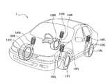
図1は、本実施形態のセミアクティブサスペンションを採用する車両1を示す斜視図で、図2は、本実施形態のセミアクティブサスペンションの装置構成を示す概略構成図である。Next, embodiments of the present invention will be described with reference to the drawings.
The present embodiment is an example of a semi-active suspension for a vehicle having four wheels, that is, left and right front wheels and left and right rear wheels.
FIG. 1 is a perspective view showing a vehicle 1 that employs a semi-active suspension of the present embodiment, and FIG. 2 is a schematic configuration diagram showing a device configuration of the semi-active suspension of the present embodiment.
(構成)
まずその構成について説明する。
図1及び図2に示すように、各車輪13FL〜13RRを個別に支持する車輪側部材14と車体側部材12との間に、それぞれサスペンション装置11FL〜11RRが介装されている。その各サスペンション装置11FL〜11RRはそれぞれ、サスペンションスプリング16FL〜16RR、及び減衰力可変式ダンパ15FL〜15RRを備える。そのサスペンションスプリング16FL〜16RR、及び減衰力可変式ダンパ15FL〜15RRはそれぞれ、軸を上下に向けて配置されて、下端部がリンクからなる上記車輪側部材14に取り付けられると共に、上端部が上記車体側部材12に取り付けられることで、対応する車輪13FL〜13RRと車体との間に介装される。(Constitution)
First, the configuration will be described.
As shown in FIGS. 1 and 2, suspension devices 11FL to 11RR are interposed between the
上記減衰力可変式ダンパ15FL〜15RRは、シリンダ内に作動油が入っており、シリンダ内の流路抵抗によって、車体側部材12の動きと車輪13FL〜13RRの動きとに応じて減衰力を発生する。また、各ダンパ15FL〜15RRの減衰力を可変にするため、減衰力可変弁17FL〜17RRが減衰力可変ダンパ15FL〜15RRのシリンダと連結する。この減衰力可変弁17FL〜17RRは、内部のソレノイドに供給される励磁電流IFL〜IRRに応じて弁体を移動させることにより流路抵抗を変更して、シリンダで発生する減衰力を変更可能な構造となっている。すなわち、上記減衰力可変弁17FL〜17RRを、制御装置31からの指令によって制御することで、減衰力可変式ダンパ15FL〜15RRの減衰力は可変制御することができる。
また、サスペンションスプリング16FL〜16RRはそれぞれ、車体の静荷重を支持するものである。そのサスペンションスプリング16FL〜16RRのばね定数は、静荷重を支えるのみの低ばね定数のものでよい。The damping force variable dampers 15FL to 15RR contain hydraulic oil in the cylinder, and generate damping force according to the movement of the vehicle
Each of the suspension springs 16FL to 16RR supports a static load of the vehicle body. The spring constants of the suspension springs 16FL to 16RR may be low spring constants that only support static loads.
一方、車体には、右前輪13FR、左後輪13RL及び右後輪13RRに対応する3箇所の位置にそれぞれ上下加速度センサ28FR、28RL及び28RRが配設されている。これら3つの上下加速度センサ28FR〜28RRはそれぞれ、検出した上下加速度に対応する信号である加速度検出値ZGFR 〜ZGRRを制御装置に出力する。
すなわち、これら上下加速度センサ28FR〜28RRはそれぞれ、図3に示すように作動する。具体的には、加速度が零のときに零の電圧を出力し、上向きの加速度が生じたときに、これに応じて正の電圧でなる加速度検出値ZG を出力し、下向きの加速度が生じたときに、これに応じて負の電圧でなる加速度検出値ZG を出力する。そして、3つの車輪13FR〜13RRの位置に対して上下加速度センサ28FR〜28RRをそれぞれ配置することにより、次のようになる。すなわち、図4に示すように、車体に対し、バウンス加速度Z″、ロール角加速度φ″及びピッチ角加速度θ″が生じたときに、各上下加速度センサ28FR〜28RRからそれぞれ下記(1)〜(3)式で表される加速度検出値ZGFR 〜ZGRR が出力される。
ZGFR =Z″−L2 θ″−L1 φ″…………(1)
ZGRL =Z″+L4 θ″+L3 φ″…………(2)
ZGRR =Z″+L4 θ″−L3 φ″…………(3)On the other hand, vertical acceleration sensors 28FR, 28RL, and 28RR are disposed at three positions corresponding to the right front wheel 13FR, the left rear wheel 13RL, and the right rear wheel 13RR, respectively. These three vertical acceleration sensors 28FR to 28RR respectively output acceleration detection values ZGFR to ZGRR, which are signals corresponding to the detected vertical acceleration, to the control device.
That is, each of the vertical acceleration sensors 28FR to 28RR operates as shown in FIG. Specifically, when the acceleration is zero, a zero voltage is output, and when an upward acceleration is generated, a positive acceleration detection value ZG is output in response to this, and a downward acceleration is generated. In response to this, the acceleration detection value ZG having a negative voltage is output. By arranging the vertical acceleration sensors 28FR to 28RR with respect to the positions of the three wheels 13FR to 13RR, respectively, the following is obtained. That is, as shown in FIG. 4, when bounce acceleration Z ″, roll angular acceleration φ ″, and pitch angular acceleration θ ″ are generated on the vehicle body, the vertical acceleration sensors 28FR to 28RR respectively perform the following (1) to ( The acceleration detection values ZGFR to ZGRR represented by the expression 3) are output.
ZGFR = Z ″ −L2 θ ″ −L1 φ ″ (1)
ZGRL = Z ″ + L4 θ ″ + L3 φ ″ ………… (2)
ZGRR = Z ″ + L4 θ ″ −L3 φ ″ (3)
上記式において、L1 は、車両1の重心点gを通る前後方向線と前右上下加速度センサ28FRとの間の左右方向距離である。L2 は、車両1の重心点gを通る左右方向線と前右上下加速度センサ28FRとの間の前後方向距離である。L3 は、車両1の重心点gを通る前後方向線と後左及び後右上下加速度センサ28RL及び28RRとの間の左右方向距離である。L4 は、車両1の重心点gを通る左右方向線と後左及び後右上下加速度センサ28RL及び28RRとの間の前後方向距離である。 In the above equation, L1 is the distance in the left-right direction between the front-rear direction line passing through the center of gravity g of the vehicle 1 and the front right vertical acceleration sensor 28FR. L2 is a distance in the front-rear direction between the left-right direction line passing through the center of gravity g of the vehicle 1 and the front right vertical acceleration sensor 28FR. L3 is the distance in the left-right direction between the front-rear direction line passing through the center of gravity g of the vehicle 1 and the rear left and rear right vertical acceleration sensors 28RL and 28RR. L4 is a distance in the front-rear direction between the left-right direction line passing through the center of gravity g of the vehicle 1 and the rear left and rear right vertical acceleration sensors 28RL and 28RR.
また、各輪13FL〜13RR毎にストロークセンサ27FL〜27RRが配置されて、各ストロークセンサ27FL〜27RRはそれぞれ、ストローク検出値を制御装置31に出力する。ストロークセンサ27FL〜27RRは、例えば、リンクなどからなる車輪側部材14の上下方向への変位角をストローク検出値として検出する。
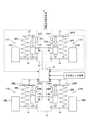
制御装置31は、図5に示すように、マイクロコンピュータ42と、このマイクロコンピュータ42から出力される減衰力指令値PFL〜PRRをD/A変換したアナログ電圧VFL〜VRRが入力される制御弁駆動回路43FL〜43RRとを備えている。
マイクロコンピュータ42は、少なくとも入力インタフェース回路42a、出力インタフェース回路42b、演算処理装置42c及び記憶装置42dを備える。In addition, stroke sensors 27FL to 27RR are arranged for the respective wheels 13FL to 13RR, and each of the stroke sensors 27FL to 27RR outputs a stroke detection value to the
As shown in FIG. 5, the
The
少なくとも、3つの上下加速度センサ28FR〜28RRの加速度検出値ZGFR 〜ZGRR 、4つのストロークセンサ27FL〜27RRからの各輪でのストローク検出値、前後加速度センサ32からの車体の前後加速度検出値、横加速度センサ33からの車体の横加速度検出値、舵角センサ34から運転者が入力したハンドル角度検出値、アクセル開度センサ35からのアクセル開度検出値、ブレーキ圧センサ36からブレーキ圧検出値、シフト位置センサ37からシフト位置検出値が、それぞれA/D変換器41を介して、入力インタフェース回路42aに入力される。また、出力インタフェース回路42bから出力される減衰力指令値PFL〜PRRが、D/A変換器43FL〜43RRでアナログ電圧VFL〜VRRに変換されて、制御弁駆動回路44FL〜44RRに供給される。 At least the acceleration detection values ZGFR to ZGRR of the three vertical acceleration sensors 28FR to 28RR, the stroke detection value of each wheel from the four stroke sensors 27FL to 27RR, the detection value of the longitudinal acceleration of the vehicle body from the
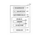
上記演算処理装置42cは、図6に示すように、車体振動情報取得部421、モード優先順位設定部422、基本目標減衰力算出部423、配分補正部424、及び指令値出力部425を備える。
車体振動情報取得部421では、入力インタフェース回路42aを介して上下加速度センサ28FR〜28RRからの上下加速度検出値ZGFR 〜ZGRRを読み込む。そして、3つの上下加速度検出値ZGFR 〜ZGRR に基づいて、下記(4)〜(6)式の演算を行って、重心点g位置でのバウンス加速度Z″、ピッチ角加速度θ″及びロール角加速度φ″を算出する。As shown in FIG. 6, the
The vehicle body vibration

また、車体振動情報取得部421は、入力インタフェース回路42aを介して各ストロークセンサ27FL〜27RRからのストローク検出値を読み込む。そして、ストローク検出値に基づき、各輪のストローク、及びストローク速度を算出する。
モード優先順位設定部422では、車体に発生している振動の振動モードについて優先順位を設定する。振動モードとしては、バウンス、ピッチ、ロールがある。The vehicle body vibration
The mode priority setting unit 422 sets the priority for the vibration mode of the vibration generated in the vehicle body. Vibration modes include bounce, pitch, and roll.
モード優先順位設定部422の処理について、図7を参照しつつ説明する。
まず、ステップS10で、各振動モード毎に、その振動モードに影響を与える検出値に基づき、それぞれ優先度を数値化して、ステップS20に移行する。
すなわち、下記式に基づいて、バウンス優先度の演算を行う。
バウンス優先度Pb=(デフォルトバウンス値)+(バウンス加速度Z″×K1)
また、下記式に基づいてピッチ優先度の演算を行う。
ピッチ優先度Pp=(アクセル開度×K2)+(ブレーキ圧×K3)
+(エンジントルク×K4)
+(シフトダウン信号(0,1値)×K5)
+(ピッチ角加速度×K6)+(デフォルトピッチ値)The processing of the mode priority setting unit 422 will be described with reference to FIG.
First, in step S10, for each vibration mode, the priority is digitized based on the detected value that affects the vibration mode, and the process proceeds to step S20.
That is, the bounce priority is calculated based on the following equation.
Bounce priority Pb = (default bounce value) + (bounce acceleration Z ″ × K1)
Also, the pitch priority is calculated based on the following equation.
Pitch priority Pp = (accelerator opening × K2) + (brake pressure × K3)
+ (Engine torque x K4)
+ (Shift down signal (0, 1 value) x K5)
+ (Pitch angular acceleration x K6) + (Default pitch value)
次に、下記式に基づいてロール優先度Prの演算を行う。
ロール優先度Pr=(ハンドル角×K7)+(ロール角加速度×K8)
+(横加速度×K9)+(デフォルトロール値)
ここで、上記K1〜K9は、各優先度や検出値のレベルを揃えるための重み付けのためのゲインである。
また、各振動モードの優先度を数値化する際に使用する、各振動モードに影響を与える検出値(振動情報)は、上記検出値を全て使用しなくても良い。
ステップS20では、求めたバウンス優先度Pb、ピッチ優先度Pp、ロール優先度Prの値を比較し、振動モードに優先順位付けを行う。ここで、一番数値が大きな優先度を、第1優先モードに設定して、処理を終了する。Next, the roll priority Pr is calculated based on the following equation.
Roll priority Pr = (steering wheel angle × K7) + (roll angular acceleration × K8)
+ (Lateral acceleration x K9) + (default roll value)
Here, K1 to K9 are gains for weighting for aligning the levels of the respective priorities and detection values.
Further, the detection values (vibration information) that affect each vibration mode used when the priority of each vibration mode is digitized do not have to use all of the detection values.
In step S20, the obtained bounce priority Pb, pitch priority Pp, and roll priority Pr are compared to prioritize the vibration modes. Here, the priority with the largest numerical value is set to the first priority mode, and the process is terminated.
次に、基本目標減衰力算出部423の処理について、図8を参照しつつ説明する。
まず、ステップS100にて、各モード毎の加速度演算値であるバウンス加速度Z″、ピッチ角加速度θ″及びロール角加速度φ″について次の処理を行う。すなわちバウンス加速度Z″、ピッチ角加速度θ″及びロール角加速度φ″について、ローパスフィルタを通して高周波ノイズ成分をカットし、さらに積分演算を行うことで、推定バウンス速度Z′,推定ピッチ速度θ′,推定ロール速度成分φ′を算出する。
次いで、ステップS110にて、下記式のように、推定バウンス速度Z′,推定ピッチ速度θ′,推定ロール速度φ′のそれぞれの値に,予め設定されたゲインを乗じて,バウンス成分目標減衰力Ux、ピッチ成分目標減衰力Up,ロール成分目標減衰力Urを算出して、ステップS120に移行する。Next, the process of the basic target damping
First, in step S100, the following processing is performed on the bounce acceleration Z ″, the pitch angular acceleration θ ″, and the roll angular acceleration φ ″, which are acceleration calculation values for each mode. That is, the bounce acceleration Z ″ and the pitch angular acceleration θ ″. For the roll angular acceleration φ ″, the high-frequency noise component is cut through a low-pass filter, and the integral calculation is performed to calculate the estimated bounce speed Z ′, the estimated pitch speed θ ′, and the estimated roll speed component φ ′.
Next, at step S110, the bounce component target damping force is multiplied by a preset gain by each of the estimated bounce speed Z ', estimated pitch speed θ', and estimated roll speed φ 'as shown in the following equation. Ux, pitch component target damping force Up, and roll component target damping force Ur are calculated, and the process proceeds to step S120.
ここで、CB、CP、Crはそれぞれ予め設定されたゲインである。
次いで、ステップS120では、各モード成分目標減衰力Ux、Up、Urを、下記式に基づき、各輪に配分して、各輪での理想目標減衰力UFL〜URRを算出する。Here, CB , CP and Cr are preset gains.
Next, in step S120, each mode component target damping force Ux, Up, Ur is distributed to each wheel based on the following formula to calculate ideal target damping forces UFL to URR for each wheel.
ここで、
LFは、車幅方向からみた重心点gから前輪までのホイルセンタ距離
LRは、車幅方向からみた重心点gから後輪までのホイルセンタ距離
TFは、車両前方からみた重心点gから右前輪までのトレッド
TRは、車両前方からみた重心点gから右後輪までのトレッド、
をそれぞれ表す。
また、ステップS130にて、各輪の理想目標減衰力UFL〜URRについて、下記式のように、各モード毎の減衰力成分に分解した値を算出して、処理を終了する。here,
LF is the wheel center distance from the center of gravity g viewed from the vehicle width direction to the front wheelLR is the wheel center distance from the center of gravity g viewed from the vehicle width direction to the rear wheelTF is the center of gravity g viewed from the front of the vehicle from to the right front wheel tread TR is the tread from the center of gravity g viewed from the vehicle front to the right rear wheel,
Respectively.
In step S130, the ideal target damping force UFL to URR of each wheel is calculated as a value decomposed into damping force components for each mode, as shown in the following formula, and the process ends.
上記配分補正部424は、各輪処理部424aと、配分補正本体部424bを備える。
各輪処理部424aは、図9のような処理を、各輪毎に行う。
すなわち、ステップS200にて、各輪でのストローク速度から、各輪で発生可能な減衰力である実現可能減衰力FFL〜FRRをそれぞれ算出する。算出は、例えば、予め設定された減衰力−速度線図のマップを使用して算出する。ここで、ストローク速度の向きと、実現可能減衰力FFL〜FRRの向きは、逆方向である。The
Each wheel processing unit 424a performs the processing shown in FIG. 9 for each wheel.
That is, in step S200, realizable damping forces FFL to FRR, which are damping forces that can be generated in each wheel, are calculated from the stroke speed in each wheel. The calculation is performed using, for example, a preset map of damping force-velocity diagram. Here, the direction of the stroke speed and the direction of the feasible damping forces FFL to FRR are opposite directions.
次に、ステップS210にて、各輪における、実現可能減衰力FFL〜FRRの符号と、理想目標減衰力UFL〜URRの符号を比較する。すなわち、実現可能減衰力FFL〜FRRの向きと理想目標減衰力UFL〜URRの向きとを比較する。符号が同じ場合には、ステップS220に移行する。符号が異なる場合には、ステップS230に移行する。
ここで、上記符号は上向き方向を正と考え,下向き方向を負と考える。Next, in step S210, the sign of the realizable damping force FFL to FRR and the sign of the ideal target damping force UFL to URR in each wheel are compared. That is, the direction of the realizable damping forces FFL to FRR and the direction of the ideal target damping forces UFL to URR are compared. If the codes are the same, the process proceeds to step S220. If the codes are different, the process proceeds to step S230.
Here, the sign is considered positive in the upward direction and negative in the downward direction.
ステップS220では、実現可能減衰力FFL〜FRRと理想目標減衰力UFL〜URRとは同方向であることを記憶して処理を終了する。
ステップS230では、理想目標減衰力UFL〜URRのうち、上記モード優先順位設定部422で設定した第1優先モードの振動モードの減衰力成分の符号と、上記実現可能減衰力FFL〜FRRの符号とを比較する。符号が同じ場合には、ステップS240に移行する。符号が異なる場合には、ステップS250に移行する。
ステップS240では、実現可能減衰力FFL〜FRRと第1優先モードの振動モードの減衰力成分とは同方向であることを記憶して処理を終了する。
ステップS250では、実現可能減衰力FFL〜FRRが、理想目標減衰力UFL〜URR及び第1優先モードの振動モードの減衰力成分とは逆方向であることを記憶して処理を終了する。In step S220, the realizable damping forces FFL to FRR and the ideal target damping forces UFL to URR are stored in the same direction, and the process ends.
In step S230, among the ideal target damping forces UFL to URR, the sign of the damping force component of the vibration mode of the first priority mode set by the mode priority setting unit 422, and the sign of the realizable damping force FFL to FRR, Compare If the codes are the same, the process proceeds to step S240. If the codes are different, the process proceeds to step S250.
In step S240, the realizable damping forces FFL to FRR and the damping force component of the vibration mode of the first priority mode are stored in the same direction, and the process ends.
In step S250, the realizable damping forces FFL to FRR are stored in the direction opposite to the ideal target damping forces UFL to URR and the damping force component of the vibration mode of the first priority mode, and the process ends.
次に、配分補正本体部424bの処理について、図10を参照しつつ説明する。
まず、ステップS300にて、各輪処理部424aの処理結果に基づき、各輪毎に、実現可能減衰力FFL〜FRRと理想目標減衰力UFL〜URRとが同方向とが同方向と判定された輪について、輪の目標減衰力FUFL〜FURRとして理想目標減衰力UFL〜URRを設定する。
次に、ステップS310にて、各輪処理部424aの処理結果に基づき、各輪毎に、実現可能減衰力FFL〜FRRと第1優先モードとなった振動モードの減衰力成分と判定された輪について、目標減衰力FUFL〜FURRとして第1優先モードの振動モードの減衰力成分を設定する。Next, processing of the distribution correction
First, in step S300, the realizable damping forces FFL to FRR and the ideal target damping forces UFL to URR are determined to be in the same direction for each wheel based on the processing result of each wheel processing unit 424a. For the wheel, ideal target damping forces UFL to URR are set as the target damping forces FUFL to FURR of the wheels.
Next, in step S310, based on the processing result of each wheel processing unit 424a, the wheels determined to be the realizable damping forces FFL to FRR and the vibration mode damping force component in the first priority mode for each wheel. Is set to the damping force component of the vibration mode of the first priority mode as the target damping forces FUFL to FURR.
次に、ステップS320にて、各輪処理部424aの処理結果に基づき、実現可能減衰力FFL〜FRRが、理想目標減衰力UFL〜URR及び第1優先モードとなった振動モードの減衰力成分(以下、第1振動モード減衰力成分と呼ぶ。)とは逆方向であると判定された輪が存在するか否かを判定する。存在しない場合には、処理を終了する。 Next, in step S320, based on the processing result of each wheel processing unit 424a, the realizable damping forces FFL to FRR become the ideal target damping forces UFL to URR and the damping force component of the vibration mode (first priority mode) ( Hereinafter, it is determined whether or not there is a wheel determined to be in the opposite direction to the first vibration mode damping force component. If it does not exist, the process ends.
一方、実現可能減衰力FFL〜FRRが、理想目標減衰力UFL〜URR及び第1振動モード減衰力成分とは逆方向であると判定された輪が存在する場合には、ステップS330に移行する。
ここで、実現可能減衰力FFL〜FRRが、理想目標減衰力UFL〜URR及び第1振動モード減衰力成分とは逆方向であると判定された輪を、逆向きの輪と呼ぶ。それ以外の輪を合致の輪と呼ぶ。
ステップS330では、逆向きの輪の第1振動モード減衰力成分を再配分する差分ΔUとする。On the other hand, if there is a wheel in which the realizable damping forces FFL to FRR are determined to be opposite to the ideal target damping forces UFL to URR and the first vibration mode damping force component, the process proceeds to step S330.
Here, the wheel in which the realizable damping forces FFL to FRR are determined to be in the opposite direction to the ideal target damping forces UFL to URR and the first vibration mode damping force component is referred to as a reverse-oriented wheel. The other rings are called mate rings.
In step S330, the difference ΔU for redistributing the first vibration mode damping force component of the wheel in the reverse direction is set.
次いで、ステップS340では、第1優先モードの振動モードに応じて、ステップS330にて計算された差分ΔUを、下記式によって増減を行って、各合致の輪にそれぞれ配分の補正を実施した後に処理を終了する。逆向きの輪が2輪ある場合には、差分ΔUについて個々に下記再配分処理を行う。
(1)第1優先モードの振動モードが、バウンスの場合
目標減衰力FUFL〜FURR= 目標減衰力FUFL〜FURR + ΔU/(合致輪の数)Next, in step S340, the difference ΔU calculated in step S330 is increased or decreased according to the following equation in accordance with the vibration mode of the first priority mode, and the distribution is corrected for each matching wheel. Exit. When there are two reverse wheels, the following redistribution processing is performed individually for the difference ΔU.
(1) When the vibration mode of the first priority mode is bounce Target damping force FUFL to FURR = Target damping force FUFL to FURR + ΔU / (number of matched wheels)
(2)第1優先モードの振動モードが、ピッチの場合
目標減衰力FUFL〜FURR= 目標減衰力FUFL〜FURR ± ΔU/(合致輪の数)
ここで、「±」は、前後輪によって替える。すなわち、逆向きの輪と前後の位置が同じ場合には「+」とし、逆向きの輪と前後の位置が異なる場合には「−」とする。
(3)第1優先モードの振動モードが、ロールの場合
目標減衰力FUFL〜FURR= 目標減衰力FUFL〜FURR ± ΔU/(合致輪の数)
ここで、「±」は、左右輪によって替える。すなわち、逆向きの輪と左右の位置が同じ場合には「+」とし、逆向きの輪と左右の位置が異なる場合には「−」とする。(2) When the vibration mode of the first priority mode is pitch Target damping force FUFL to FURR = Target damping force FUFL to FURR ± ΔU / (number of matched wheels)
Here, “±” is changed depending on the front and rear wheels. That is, “+” is set when the front and rear positions are the same as the reverse direction, and “−” is set when the front and back positions are different from the reverse direction.
(3) When the vibration mode of the first priority mode is roll Target damping force FUFL to FURR = Target damping force FUFL to FURR ± ΔU / (number of matched wheels)
Here, “±” is changed depending on the left and right wheels. That is, “+” is set when the left and right positions are the same as the opposite direction wheel, and “−” is set when the left and right positions are different from the opposite direction.
次に、指令値出力部425では、上記配分補正部424で求めた各輪の目標減衰力FUFL〜FURRに応じた、減衰力可変弁17FL〜17RRに対する減衰力指令値PFL〜PRRを算出して、これらを出力インタフェース回路42bを介してD/A変換器43FL〜43RRに出力する。
ここで、基本目標減衰力算出部423は、目標減衰力算出手段を構成する。基本目標減衰力算出部423のステップS100及びステップS110は、理想目標減衰力算出手段を構成し、バウンス成分目標減衰力Ux、ピッチ成分目標減衰力Up,ロール成分目標減衰力Urは、車体全体の理想目標減衰力の例を示す。モード優先順位設定部422は、振動モード優先順位設定手段を構成する。各輪処理部424aのステップS200は、発生方向検出手段を構成する。配分補正部424は、目標減衰力補正手段を構成する。
また、理想目標減衰力UFL〜URRは、各輪のダンパで発生する理想の目標減衰力の一例を示す。目標減衰力FUFL〜FURRは、補正後の各輪のダンパで発生する目標減衰力の一例を示す。Next, the command
Here, the basic target damping
The ideal target damping forces UFL to URR indicate examples of ideal target damping forces generated by the dampers of the respective wheels. The target damping forces FUFL to FURR indicate an example of the target damping force generated by the corrected damper of each wheel.
(動作)
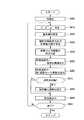
次に、上記実施形態の動作を演算処理装置42cの処理手順を示す図11のフローチャートを参照して説明する。
イグニッションスイッチがオン状態となると、制御装置31に電源が投入され、その演算処理装置42cで、車両1の挙動抑制制御の処理が実行される。すなわち、先ずステップS400で初期化を実行して、制御に必要な各パラメータの設定等を行う。
次に、ステップS410に移行して、振動情報取得部で、上下加速度センサ28FR〜28RRなどからの信号に基づき、車両重心点gでのバウンス上下加速度Z″、ピッチ加速度θ″、ロール加速度φ″などを算出する。(Operation)
Next, the operation of the above embodiment will be described with reference to the flowchart of FIG. 11 showing the processing procedure of the
When the ignition switch is turned on, the
Next, the process proceeds to step S410, where the vibration information acquisition unit performs bounce vertical acceleration Z ″, pitch acceleration θ ″, roll acceleration φ ″ at the vehicle center of gravity g based on signals from the vertical acceleration sensors 28FR to 28RR. Etc. are calculated.
次に、ステップS420に移行し、車体の振動状態から振動モードの優先順位を設定する。
次に、ステップS430に移行して、車体に生じている振動モードから各輪の理想目標減衰力UFL〜URR、及びその各輪の理想目標減衰力UFL〜URRの各モード毎の減衰力成分を求める。
次に、ステップS440に移行して、各輪単位に、実現可能減衰力FFL〜FRRと理想目標減衰力UFL〜URRとの向きが同方向か否かを判定し、さらに異なる場合には実願可能減衰力と第1振動モード減衰力成分とが同方向か否かを判定し記憶する。
次に、ステップS450に移行して、実現可能減衰力FFL〜FRRと理想目標減衰力UFL〜URRとの向きが同方向の輪について、理想目標減衰力UFL〜URRを目標減衰力FUFL〜FURRに設定する。Next, the process proceeds to step S420, and the priority order of the vibration mode is set from the vibration state of the vehicle body.
Next, the process proceeds to step S430, where the ideal target damping force UFL to URR of each wheel and the damping force component for each mode of the ideal target damping force UFL to URR of each wheel are determined from the vibration mode generated in the vehicle body. Ask.
Next, the process proceeds to step S440, where it is determined whether or not the directions of the realizable damping forces FFL to FRR and the ideal target damping forces UFL to URR are the same direction for each wheel. It is determined and stored whether or not the possible damping force and the first vibration mode damping force component are in the same direction.
Next, the process proceeds to step S450, and the ideal target damping force UFL to URR is changed to the target damping force FUFL to FURR for the wheels in which the realizable damping forces FFL to FRR and the ideal target damping forces UFL to URR have the same direction. Set.
次に、ステップS460に移行して、実願可能減衰力と第1振動モード減衰力成分とが同方向の輪について、第1振動モード減衰力成分を目標減衰力FUFL〜FURRに設定する。
次に、ステップS470にて、逆向きの輪があるか否かを判定する。逆向きの輪が無い場合にはステップS490に移行する。
逆向きの輪がある場合にはステップS480に移行して、逆向きの輪の第1振動モード減衰力成分を、他の一致の輪に配分する補正を、各一致の輪の目標減衰力FUFL〜FURRに対して実施してステップS490に移行する。
ステップS490では、例えば予め記憶装置42dに格納された減衰力指令値算出マップを参照して各目標減衰力FUFL〜FURRに対応する減衰力指令値を算出し、算出した減衰力指令値を出力インタフェース回路42bを介してD/A変換器43FL〜43RRに出力する。Next, the process proceeds to step S460, and the first vibration mode damping force component is set to the target damping forces FUFL to FURR for a wheel in which the actual application possible damping force and the first vibration mode damping force component are in the same direction.
Next, in step S470, it is determined whether there is a reverse wheel. If there is no reverse ring, the process proceeds to step S490.
If there is a reverse wheel, the process proceeds to step S480, and correction for allocating the first vibration mode damping force component of the reverse wheel to other matching wheels is performed, and the target damping force FUFL of each matching wheel is corrected. The process is performed for FURR, and the process proceeds to step S490.
In step S490, for example, a damping force command value corresponding to each target damping force FUFL to FURR is calculated with reference to a damping force command value calculation map stored in advance in the
次いでステップS500に移行して、所定の制御終了条件を満足するか否かを判定し、制御終了条件を満足しないときには、前記ステップS410に移行して制御を継続する。また、制御終了条件を満足するときには、制御を終了する。ここで、制御終了条件としては、イグニッションスイッチがオン状態からオフ状態に切換わった後、所定時間が経過したときに設定され、このイグニッションスイッチがオフ状態となった後も制御装置31の電源の投入状態を自己保持する。 Next, the process proceeds to step S500 to determine whether or not a predetermined control end condition is satisfied. If the control end condition is not satisfied, the process proceeds to step S410 and the control is continued. When the control end condition is satisfied, the control is ended. Here, the control end condition is set when a predetermined time elapses after the ignition switch is switched from the on-state to the off-state, and even after the ignition switch is turned off, Self-maintain the input state.
(効果)
(1)車体に発生する全ての振動モードを抑制するための各輪の理想目標減衰力UFL〜URRと、各輪の実現可能減衰力FFL〜FRRとが、全ての輪で同方向の場合には、全ての輪において、理想目標減衰力UFL〜URRと同方向に減衰力を発生可能である。このことから、各輪の目標減衰力FUFL〜FURRを理想目標減衰力UFL〜URRとして、全ての振動モードによる車体の振動状態を抑制する。なおこのとき、従来例のような補正を更に行っても良い。(effect)
(1) When the ideal target damping force UFL to URR of each wheel for suppressing all vibration modes generated in the vehicle body and the feasible damping force FFL to FRR of each wheel are the same in all the wheels Can generate a damping force in the same direction as the ideal target damping forces UFL to URR in all the wheels. Thus, the vibration state of the vehicle body in all vibration modes is suppressed with the target damping forces FUFL to FURR of each wheel as the ideal target damping forces UFL to URR. At this time, correction as in the conventional example may be further performed.
(2)一方、理想目標減衰力UFL〜URRと実現可能減衰力FFL〜FRRとが逆方向で、理想目標減衰力UFL〜URRの向きに減衰力を発生出来ない輪がある場合には、理想目標減衰力UFL〜URRのうち、第1優先モードに対応する第1振動モード減衰力成分と、実現可能減衰力FFL〜FRRとが同方向の場合には、当該逆向きの輪の目標減衰力FUFL〜FURRを第1振動モード減衰力成分とすることで、狙いの振動モードの車体の振動を優先的に抑制することが可能となる。(2) On the other hand, if there is a wheel in which the ideal target damping force UFL to URR and the realizable damping force FFL to FRR are in opposite directions and no damping force can be generated in the direction of the ideal target damping force UFL to URR, Among the target damping forces UFL to URR, when the first vibration mode damping force component corresponding to the first priority mode and the feasible damping forces FFL to FRR are in the same direction, the target damping force of the wheel in the opposite direction By setting FUFL to FURR as the first vibration mode damping force component, it is possible to preferentially suppress the vibration of the vehicle body in the target vibration mode.
ここで、狙いの振動モードとして、上述のように3つの振動モードの内、車体の振動状態に大きく寄与していると想定される振動モードを選択することで、一番車体の振動状態に影響のある振動を抑えることで、より有効に振動抑制が可能となる。
なお、理想目標減衰力UFL〜URRと実現可能減衰力FFL〜FRRの向きが一致している輪では、全ての振動モードを抑制する方向に減衰力が発生する。Here, as the target vibration mode, by selecting a vibration mode that is assumed to contribute greatly to the vibration state of the vehicle body among the three vibration modes as described above, the vibration mode of the vehicle body is most affected. By suppressing the vibration with the vibration, the vibration can be suppressed more effectively.
It should be noted that a damping force is generated in a direction in which all vibration modes are suppressed in a wheel in which the directions of the ideal target damping forces UFL to URR and the realizable damping forces FFL to FRR coincide.
(3)さらに、理想目標減衰力UFL〜URRの向きにも第1振動モード減衰力成分の方向にも、減衰力を発生出来ない輪がある場合には、その輪の第1振動モード減衰力成分を他の合致の輪に配分する補正を行うことで、第1優先モードの振動モードを狙って車体の振動を抑制することが可能となる。(3) Furthermore, if there is a wheel that cannot generate a damping force in either the direction of the ideal target damping force UFL to URR or the direction of the first vibration mode damping force component, the first vibration mode damping force of that wheel. By performing the correction to distribute the components to the other matching wheels, it is possible to suppress the vibration of the vehicle body aiming at the vibration mode of the first priority mode.
(応用)
(1)上記説明では、車両重心点廻りのバウンス、ピッチ、ロールを抑制する制御例で説明しているが、車両重心点とは異なる位置の複数の振動モード(例えば、バウンス、ピッチ、ロール)を抑制するように理想目標減衰力UFL〜URRを求めて、抑制制御を実施する場合でも適用可能である。
この場合には、車両重心点以外の仮想制御点での上下加速度(車両重心点での上下加速度、ピッチ角速度、ロール角速度、及び重心点からの距離によって算出出来る。)、重心点廻りのピッチ角加速度θ″及びロール角加速度φ″を使用して、仮想制御点におけるバウンス成分減衰力、ピッチ成分減衰力、ロール成分減衰力を算出し、更に、その仮想制御点における減衰力を、車両重心点におけるババウンス成分減衰力、ピッチ成分減衰力、ロール成分減衰力に換算して、上述の処理を行えば良い。(application)
(1) In the above description, the control example for suppressing the bounce, pitch, and roll around the vehicle center of gravity is described, but a plurality of vibration modes (for example, bounce, pitch, roll) at positions different from the vehicle center of gravity. Even when the ideal target damping forces UFL to URR are determined so as to suppress the suppression control and the suppression control is performed, the present invention is applicable.
In this case, the vertical acceleration at a virtual control point other than the vehicle center of gravity (which can be calculated by the vertical acceleration at the vehicle center of gravity, the pitch angular velocity, the roll angular velocity, and the distance from the center of gravity), the pitch angle around the center of gravity. The bounce component damping force, the pitch component damping force, and the roll component damping force at the virtual control point are calculated using the acceleration θ ″ and the roll angular acceleration φ ″, and the damping force at the virtual control point is calculated as the vehicle center of gravity point. The bounce component damping force, pitch component damping force, and roll component damping force may be converted into the above-described processing.
(2)また、上記実施形態では、理想目標減衰力UFL〜URRの向きにも第1振動モード減衰力成分の方向にも、減衰力を発生出来ない輪がある場合には、その輪の第1振動モード減衰力成分を、他の合致の輪の目標減衰力に再配分する補正を行う場合を例示しているが、これに限定されない。例えば、振動モードの優先順位において、第1優先モードのポイントと、2番目に優先度が大きな振動モードとのポイントの差が所定以下の場合には、2番目に優先度が大きな振動モードの振動モード減衰力成分と、実現可能減衰力FFL〜FRRとが同方向の場合には、目標減衰力FUFL〜FURRを、2番目に優先度が大きな振動モードの振動モード減衰力成分としても良い。(2) In the above embodiment, if there is a ring that cannot generate a damping force in either the direction of the ideal target damping force UFL to URR or the direction of the first vibration mode damping force component, Although the case where the correction which redistributes 1 vibration mode damping force component to the target damping force of the wheel of another match is illustrated, it is not limited to this. For example, if the difference between the points of the first priority mode and the second highest priority vibration mode is less than or equal to a predetermined value in the vibration mode priority order, the vibration of the second highest priority vibration mode When the mode damping force component and the feasible damping forces FFL to FRR are in the same direction, the target damping forces FUFL to FURR may be used as the vibration mode damping force component of the vibration mode having the second highest priority.
(3)各振動モードに影響のある検出値としては、上述の検出値に限定されない。例えば、路面の凹凸などを検出してバウンスの優先度を設定したりしても良い。
(4)振動モードの優先順位は、振動状態とは関係なく固定に設定しておいたり、運転者が選択可能となっていたりしても良い。
(5)また、振動モードを、バウンス、ピッチ、ロールの3分類する場合を例示しているが、例えば、ピッチを前向きのピッチと、後ろ向きのピッチとの2つで優先度のポイント評価を変更したりしても良い。(3) Detection values that affect each vibration mode are not limited to the detection values described above. For example, the bounce priority may be set by detecting unevenness on the road surface.
(4) The priority order of the vibration mode may be fixed regardless of the vibration state, or may be selectable by the driver.
(5) Also, the vibration mode is classified into three types: bounce, pitch, and roll. For example, the point evaluation of priority is changed with two pitches: forward pitch and backward pitch. You may do it.
1 車両
11FL〜11RR サスペンション装置
12 車体側部材
14 車輪側部材
15FL〜15RR ダンパ
17FL〜17RR 減衰力可変弁
27FL〜27FL ストロークセンサ
28FL〜28RR 上下加速度センサ
31 制御装置
42c 演算処理装置
421 車体振動情報取得部
422 モード優先順位設定部
423 基本目標減衰力算出部
424 配分補正部
424a 各輪処理部
424b 配分補正本体部
425 指令値出力部
FFL〜FRR 実現可能減衰力
FUFL〜FURR 目標減衰力(補正後の目標減衰力)
UFL〜URR 各輪の理想目標減衰力(各輪のダンパで発生する理想の目標減衰力)
Up ピッチ成分目標減衰力(車体全体の理想目標減衰力)
Ur ロール成分目標減衰力(車体全体の理想目標減衰力)
Ux バウンス成分目標減衰力(車体全体の理想目標減衰力)
Pb バウンス優先度
Pp ピッチ優先度
Pr ロール優先度DESCRIPTION OF SYMBOLS 1 Vehicle 11FL-
UFL to URR Ideal target damping force for each wheel (ideal target damping force generated by the damper of each wheel)
Up Pitch component target damping force (ideal target damping force of the entire vehicle body)
Ur Roll component target damping force (ideal target damping force for the entire vehicle body)
Ux bounce component target damping force (ideal target damping force of the entire vehicle body)
Pb Bounce priority Pp Pitch priority Pr Roll priority
Claims (5)
Translated fromJapanese車体の振動状態に基づき、当該車体の振動状態を目標の振動状態とする車体全体の理想目標減衰力を算出する理想目標減衰力算出手段と、
その理想目標減衰力算出手段が算出した車体全体の理想目標減衰力を、各輪のダンパで発生させる目標減衰力として配分する配分手段と、
上記車体の振動状態を構成する複数の振動モードについて優先順位を設定する振動モード優先順位設定手段と、
各輪で発生可能な実現可能減衰力の向きを判定する発生方向検出手段と、
各輪のダンパで減衰力を発生可能な向き及び上記優先順位に基づき、上記配分手段が配分した各輪のダンパの目標減衰力を補正する目標減衰力補正手段と、を備え、
目標減衰力補正手段は、
目標減衰力の向きと実現可能減衰力の向きとが異なる輪において、その輪の目標減衰力のうち、振動モード優先順位判定手段で優先順位が高いと設定された振動モードの減衰力成分の向きと、実現可能減衰力の向きとが同方向と判定した場合には、上記目標減衰力の向きと実現可能減衰力の向きとが異なる輪の目標減衰力を、当該目標減衰力のうちの、優先順位が高いと設定された振動モードの減衰力成分とすることを特徴とする車両のセミアクティブサスペンション。A plurality of dampers interposed between each wheel and the vehicle body and capable of adjusting a damping force generated;
An ideal target damping force calculating means for calculating an ideal target damping force of the entire vehicle body based on the vibration state of the vehicle body, with the vibration state of the vehicle body as a target vibration state;
A distribution unit that distributes the ideal target damping force of the entire vehicle body calculated by the ideal target damping force calculation unit as a target damping force generated by a damper of each wheel;
Vibration mode priority setting means for setting priorities for a plurality of vibration modes constituting the vibration state of the vehicle body;
Generation direction detection means for determining the direction of a realizable damping force that can be generated in each wheel;
A target damping force correcting means for correcting the target damping force of each wheel damper distributed by the distributing means based on the direction in which the damping force can be generated by the damper of each wheel and the priority, and
The target damping force correction means is
The direction of the damping force component of the vibration mode for which the priority is set to be higher by the vibration mode priority determination means in the target damping force of the wheel in which the direction of the target damping force and the direction of the realizable damping force are different And when the direction of the realizable damping force is determined to be the same direction, the target damping force of the wheel having the direction of the target damping force and the direction of the realizable damping force is different from the target damping force. A semi-active suspension for a vehicle characterizedby havinga damping force component of a vibration mode set to a higher priority .
上記目標減衰力の向きと実現可能減衰力の向きとが異なる輪において、上記優先順位が高いと設定された振動モードの減衰力成分の向きと、実現可能減衰力の向きとが逆方向と判定した場合には、その優先順位が高いと設定された振動モードの減衰力成分を、他の減衰力が発生可能な輪に配分することを特徴とする請求項1に記載した車両のセミアクティブサスペンション。The target damping force correction means is
In a wheel in which the direction of the target damping force and the direction of the realizable damping force are different, the direction of the damping force component of the vibration mode that is set as high priority is determined to be opposite to the direction of the realizable damping force. the case, the semi-active suspension for a vehicle according to claim1 in which the damping force component of the higher priority and the set oscillation mode, characterized in that the other damping force is distributed to the possible wheel generator .
上記ダンパで発生可能な減衰力の向きと対応する上記目標減衰力の向きとが反対方向の輪があると判定すると、上記車体の振動状態を構成する複数の振動モードの優先順位と、各輪のダンパで発生可能な減衰力の向きとに基づき、各輪のダンパの目標減衰力を補正し、
目標減衰力の向きと実現可能減衰力の向きとが異なる輪において、その輪の目標減衰力のうち、優先順位が高いと設定された振動モードの減衰力成分の向きと、実現可能減衰力の向きとが同方向と判定した場合には、上記目標減衰力の向きと実現可能減衰力の向きとが異なる輪の目標減衰力を、当該目標減衰力のうちの、優先順位が高いと設定された振動モードの減衰力成分とすることを特徴とする車両の挙動抑制制御方法。A damper that is interposed between each wheel and the vehicle body and that can adjust the generated damping force is provided, and the damper of each wheel is adjusted to the target damping force required to make the vehicle body vibration state the target vibration state. In a vehicle behavior suppression control method that suppresses vehicle behavior by controlling damping force,
If it is determined that there is a wheel whose direction of the damping force that can be generated by the damper is opposite to the direction of the corresponding target damping force, the priority order of the plurality of vibration modes that constitute the vibration state of the vehicle body, and each wheel Based on the direction of the damping force that can be generated by the damper, the target damping force of each wheel damper is corrected,
For a wheel with different target damping force direction and realizable damping force direction, out of the target damping force of the wheel, the direction of the damping force component of the vibration mode that is set as high priority and the realizable damping force If the direction is determined to be the same direction, the target damping force of the wheel having a different direction of the target damping force and the direction of the realizable damping force is set as the highest priority among the target damping forces. A vehicle behavior suppression control method characterizedby using a damping force component in a vibration mode .
Priority Applications (1)
| Application Number | Priority Date | Filing Date | Title |
|---|---|---|---|
| JP2007203227AJP5050717B2 (en) | 2007-08-03 | 2007-08-03 | Vehicle semi-active suspension and vehicle behavior suppression control method |
Applications Claiming Priority (1)
| Application Number | Priority Date | Filing Date | Title |
|---|---|---|---|
| JP2007203227AJP5050717B2 (en) | 2007-08-03 | 2007-08-03 | Vehicle semi-active suspension and vehicle behavior suppression control method |
Publications (2)
| Publication Number | Publication Date |
|---|---|
| JP2009035220A JP2009035220A (en) | 2009-02-19 |
| JP5050717B2true JP5050717B2 (en) | 2012-10-17 |
Family
ID=40437516
Family Applications (1)
| Application Number | Title | Priority Date | Filing Date |
|---|---|---|---|
| JP2007203227AExpired - Fee RelatedJP5050717B2 (en) | 2007-08-03 | 2007-08-03 | Vehicle semi-active suspension and vehicle behavior suppression control method |
Country Status (1)
| Country | Link |
|---|---|
| JP (1) | JP5050717B2 (en) |
Families Citing this family (19)
| Publication number | Priority date | Publication date | Assignee | Title |
|---|---|---|---|---|
| US9162573B2 (en) | 2010-06-03 | 2015-10-20 | Polaris Industries Inc. | Electronic throttle control |
| WO2013111738A1 (en)* | 2012-01-25 | 2013-08-01 | 日産自動車株式会社 | Vehicle control system and vehicle control method |
| JP5733431B2 (en) | 2012-01-25 | 2015-06-10 | 日産自動車株式会社 | Vehicle control apparatus and vehicle control method |
| EP2917054B1 (en) | 2012-11-07 | 2018-09-05 | Polaris Industries Inc. | Vehicle having suspension with continuous damping control |
| US9205717B2 (en) | 2012-11-07 | 2015-12-08 | Polaris Industries Inc. | Vehicle having suspension with continuous damping control |
| CN107406094B (en) | 2014-10-31 | 2020-04-14 | 北极星工业有限公司 | System and method for controlling a vehicle |
| MX2017014403A (en) | 2015-05-15 | 2018-04-11 | Polaris Inc | UTILITY VEHICLE. |
| CN110121438B (en) | 2016-11-18 | 2023-01-31 | 北极星工业有限公司 | vehicles with adjustable suspension |
| US10406884B2 (en) | 2017-06-09 | 2019-09-10 | Polaris Industries Inc. | Adjustable vehicle suspension system |
| US10946736B2 (en) | 2018-06-05 | 2021-03-16 | Polaris Industries Inc. | All-terrain vehicle |
| US10987987B2 (en) | 2018-11-21 | 2021-04-27 | Polaris Industries Inc. | Vehicle having adjustable compression and rebound damping |
| MX2021012802A (en) | 2019-04-30 | 2021-11-12 | Polaris Inc | VEHICLE. |
| US11691674B2 (en) | 2020-05-15 | 2023-07-04 | Polaris Industries Inc. | Off-road vehicle |
| US12187127B2 (en) | 2020-05-15 | 2025-01-07 | Polaris Industries Inc. | Off-road vehicle |
| US12397878B2 (en) | 2020-05-20 | 2025-08-26 | Polaris Industries Inc. | Systems and methods of adjustable suspensions for off-road recreational vehicles |
| MX2022015902A (en) | 2020-07-17 | 2023-01-24 | Polaris Inc | Adjustable suspensions and vehicle operation for off-road recreational vehicles. |
| CN113635726B (en)* | 2021-08-31 | 2023-05-09 | 东风汽车有限公司东风日产乘用车公司 | Integrated control method and system for whole vehicle semi-active suspension system |
| MX2023006716A (en) | 2022-06-13 | 2023-12-14 | Polaris Inc | POWER TRAIN FOR UTILITY VEHICLE. |
| CN115674982B (en)* | 2022-10-18 | 2024-07-26 | 中国北方车辆研究所 | Two-stage superposition control method for electromechanical suspension |
Family Cites Families (4)
| Publication number | Priority date | Publication date | Assignee | Title |
|---|---|---|---|---|
| JP3196494B2 (en)* | 1994-02-25 | 2001-08-06 | 日産自動車株式会社 | Suspension control device |
| JP3209030B2 (en)* | 1995-03-10 | 2001-09-17 | 日産自動車株式会社 | Vehicle suspension control device |
| JP3209031B2 (en)* | 1995-03-10 | 2001-09-17 | 日産自動車株式会社 | Vehicle suspension control device |
| JP3374391B2 (en)* | 1997-09-22 | 2003-02-04 | トヨタ自動車株式会社 | Vehicle damping force control device |
- 2007
- 2007-08-03JPJP2007203227Apatent/JP5050717B2/ennot_activeExpired - Fee Related
Also Published As
| Publication number | Publication date |
|---|---|
| JP2009035220A (en) | 2009-02-19 |
Similar Documents
| Publication | Publication Date | Title |
|---|---|---|
| JP5050717B2 (en) | Vehicle semi-active suspension and vehicle behavior suppression control method | |
| JP5809474B2 (en) | Body posture control device | |
| JP2009035218A (en) | Active suspension and method for suppressing posture change of vehicle | |
| JP5321603B2 (en) | Vehicle stabilizer control device | |
| CN111137096B (en) | Control system for variable damping force damper | |
| JP6546675B2 (en) | Electronic variable suspension system | |
| CN101868363A (en) | Damping force control device for vehicles | |
| JP2009006882A (en) | Active suspension and method for suppressing vehicle posture change | |
| JP5151161B2 (en) | Vehicle state estimation device and shock absorber control device | |
| JP2009227036A (en) | Suspension control device and method | |
| JP2009006884A (en) | Active suspension and method for suppressing vehicle posture change | |
| JP5808615B2 (en) | Suspension control device | |
| JP2023037113A (en) | Vehicle and control method of vehicular suspension | |
| JP2008247357A (en) | Suspension control device | |
| JP5402874B2 (en) | Vehicle control device | |
| JP4486979B2 (en) | Control device for damping force variable damper | |
| JPH0986131A (en) | Suspension control device | |
| JP5050716B2 (en) | Active suspension and method for suppressing posture change of vehicle | |
| JP4435303B2 (en) | Control device for damping force variable damper | |
| JP5571510B2 (en) | Suspension control device | |
| JP2009006883A (en) | Active suspension and method for suppressing vehicle posture change | |
| JP2009137342A (en) | Control device for damping force variable damper | |
| JP5131682B2 (en) | Control device for variable damping force damper | |
| JP5148679B2 (en) | Control device and control method for damping force variable damper | |
| KR100648811B1 (en) | How to control an active geometry controlled suspension system |
Legal Events
| Date | Code | Title | Description |
|---|---|---|---|
| A621 | Written request for application examination | Free format text:JAPANESE INTERMEDIATE CODE: A621 Effective date:20100728 | |
| RD04 | Notification of resignation of power of attorney | Free format text:JAPANESE INTERMEDIATE CODE: A7424 Effective date:20100917 | |
| A521 | Written amendment | Free format text:JAPANESE INTERMEDIATE CODE: A523 Effective date:20100929 | |
| A977 | Report on retrieval | Free format text:JAPANESE INTERMEDIATE CODE: A971007 Effective date:20111215 | |
| A131 | Notification of reasons for refusal | Free format text:JAPANESE INTERMEDIATE CODE: A131 Effective date:20111220 | |
| A521 | Written amendment | Free format text:JAPANESE INTERMEDIATE CODE: A523 Effective date:20120209 | |
| TRDD | Decision of grant or rejection written | ||
| A01 | Written decision to grant a patent or to grant a registration (utility model) | Free format text:JAPANESE INTERMEDIATE CODE: A01 Effective date:20120626 | |
| A01 | Written decision to grant a patent or to grant a registration (utility model) | Free format text:JAPANESE INTERMEDIATE CODE: A01 | |
| A61 | First payment of annual fees (during grant procedure) | Free format text:JAPANESE INTERMEDIATE CODE: A61 Effective date:20120709 | |
| R150 | Certificate of patent or registration of utility model | Free format text:JAPANESE INTERMEDIATE CODE: R150 | |
| FPAY | Renewal fee payment (event date is renewal date of database) | Free format text:PAYMENT UNTIL: 20150803 Year of fee payment:3 | |
| LAPS | Cancellation because of no payment of annual fees |