JP5043837B2 - Medical connector with closable male luer - Google Patents
Medical connector with closable male luerDownload PDFInfo
- Publication number
- JP5043837B2 JP5043837B2JP2008520351AJP2008520351AJP5043837B2JP 5043837 B2JP5043837 B2JP 5043837B2JP 2008520351 AJP2008520351 AJP 2008520351AJP 2008520351 AJP2008520351 AJP 2008520351AJP 5043837 B2JP5043837 B2JP 5043837B2
- Authority
- JP
- Japan
- Prior art keywords
- connector
- valve member
- housing
- fluid
- connector according
- Prior art date
- Legal status (The legal status is an assumption and is not a legal conclusion. Google has not performed a legal analysis and makes no representation as to the accuracy of the status listed.)
- Active
Links
Images


Classifications
- A—HUMAN NECESSITIES
- A61—MEDICAL OR VETERINARY SCIENCE; HYGIENE
- A61M—DEVICES FOR INTRODUCING MEDIA INTO, OR ONTO, THE BODY; DEVICES FOR TRANSDUCING BODY MEDIA OR FOR TAKING MEDIA FROM THE BODY; DEVICES FOR PRODUCING OR ENDING SLEEP OR STUPOR
- A61M39/00—Tubes, tube connectors, tube couplings, valves, access sites or the like, specially adapted for medical use
- A61M39/10—Tube connectors; Tube couplings
- A61M39/12—Tube connectors; Tube couplings for joining a flexible tube to a rigid attachment
- A—HUMAN NECESSITIES
- A61—MEDICAL OR VETERINARY SCIENCE; HYGIENE
- A61M—DEVICES FOR INTRODUCING MEDIA INTO, OR ONTO, THE BODY; DEVICES FOR TRANSDUCING BODY MEDIA OR FOR TAKING MEDIA FROM THE BODY; DEVICES FOR PRODUCING OR ENDING SLEEP OR STUPOR
- A61M39/00—Tubes, tube connectors, tube couplings, valves, access sites or the like, specially adapted for medical use
- A61M39/22—Valves or arrangement of valves
- A61M39/26—Valves closing automatically on disconnecting the line and opening on reconnection thereof
- A—HUMAN NECESSITIES
- A61—MEDICAL OR VETERINARY SCIENCE; HYGIENE
- A61M—DEVICES FOR INTRODUCING MEDIA INTO, OR ONTO, THE BODY; DEVICES FOR TRANSDUCING BODY MEDIA OR FOR TAKING MEDIA FROM THE BODY; DEVICES FOR PRODUCING OR ENDING SLEEP OR STUPOR
- A61M39/00—Tubes, tube connectors, tube couplings, valves, access sites or the like, specially adapted for medical use
- A61M39/10—Tube connectors; Tube couplings
- A61M2039/1033—Swivel nut connectors, e.g. threaded connectors, bayonet-connectors
- A—HUMAN NECESSITIES
- A61—MEDICAL OR VETERINARY SCIENCE; HYGIENE
- A61M—DEVICES FOR INTRODUCING MEDIA INTO, OR ONTO, THE BODY; DEVICES FOR TRANSDUCING BODY MEDIA OR FOR TAKING MEDIA FROM THE BODY; DEVICES FOR PRODUCING OR ENDING SLEEP OR STUPOR
- A61M39/00—Tubes, tube connectors, tube couplings, valves, access sites or the like, specially adapted for medical use
- A61M39/10—Tube connectors; Tube couplings
- A61M2039/1066—Tube connectors; Tube couplings having protection means, e.g. sliding sleeve to protect connector itself, shrouds to protect a needle present in the connector, protective housing, isolating sheath
- A—HUMAN NECESSITIES
- A61—MEDICAL OR VETERINARY SCIENCE; HYGIENE
- A61M—DEVICES FOR INTRODUCING MEDIA INTO, OR ONTO, THE BODY; DEVICES FOR TRANSDUCING BODY MEDIA OR FOR TAKING MEDIA FROM THE BODY; DEVICES FOR PRODUCING OR ENDING SLEEP OR STUPOR
- A61M39/00—Tubes, tube connectors, tube couplings, valves, access sites or the like, specially adapted for medical use
- A61M39/22—Valves or arrangement of valves
- A61M39/26—Valves closing automatically on disconnecting the line and opening on reconnection thereof
- A61M2039/261—Valves closing automatically on disconnecting the line and opening on reconnection thereof where the fluid space within the valve is increasing upon disconnection
- A—HUMAN NECESSITIES
- A61—MEDICAL OR VETERINARY SCIENCE; HYGIENE
- A61M—DEVICES FOR INTRODUCING MEDIA INTO, OR ONTO, THE BODY; DEVICES FOR TRANSDUCING BODY MEDIA OR FOR TAKING MEDIA FROM THE BODY; DEVICES FOR PRODUCING OR ENDING SLEEP OR STUPOR
- A61M39/00—Tubes, tube connectors, tube couplings, valves, access sites or the like, specially adapted for medical use
- A61M39/22—Valves or arrangement of valves
- A61M39/26—Valves closing automatically on disconnecting the line and opening on reconnection thereof
- A61M2039/263—Valves closing automatically on disconnecting the line and opening on reconnection thereof where the fluid space within the valve is decreasing upon disconnection
- A—HUMAN NECESSITIES
- A61—MEDICAL OR VETERINARY SCIENCE; HYGIENE
- A61M—DEVICES FOR INTRODUCING MEDIA INTO, OR ONTO, THE BODY; DEVICES FOR TRANSDUCING BODY MEDIA OR FOR TAKING MEDIA FROM THE BODY; DEVICES FOR PRODUCING OR ENDING SLEEP OR STUPOR
- A61M39/00—Tubes, tube connectors, tube couplings, valves, access sites or the like, specially adapted for medical use
- A61M39/22—Valves or arrangement of valves
- A61M39/26—Valves closing automatically on disconnecting the line and opening on reconnection thereof
- A61M2039/267—Valves closing automatically on disconnecting the line and opening on reconnection thereof having a sealing sleeve around a tubular or solid stem portion of the connector
- A61M2039/268—Valves closing automatically on disconnecting the line and opening on reconnection thereof having a sealing sleeve around a tubular or solid stem portion of the connector wherein the stem portion is moved for opening and closing the valve, e.g. by translation, rotation
- Y—GENERAL TAGGING OF NEW TECHNOLOGICAL DEVELOPMENTS; GENERAL TAGGING OF CROSS-SECTIONAL TECHNOLOGIES SPANNING OVER SEVERAL SECTIONS OF THE IPC; TECHNICAL SUBJECTS COVERED BY FORMER USPC CROSS-REFERENCE ART COLLECTIONS [XRACs] AND DIGESTS
- Y10—TECHNICAL SUBJECTS COVERED BY FORMER USPC
- Y10T—TECHNICAL SUBJECTS COVERED BY FORMER US CLASSIFICATION
- Y10T137/00—Fluid handling
- Y10T137/8593—Systems
- Y10T137/87917—Flow path with serial valves and/or closures
- Y10T137/87925—Separable flow path section, valve or closure in each
- Y10T137/87973—Coupling interlocked with valve, or closure or actuator
Landscapes
- Health & Medical Sciences (AREA)
- Heart & Thoracic Surgery (AREA)
- Pulmonology (AREA)
- Engineering & Computer Science (AREA)
- Anesthesiology (AREA)
- Biomedical Technology (AREA)
- Hematology (AREA)
- Life Sciences & Earth Sciences (AREA)
- Animal Behavior & Ethology (AREA)
- General Health & Medical Sciences (AREA)
- Public Health (AREA)
- Veterinary Medicine (AREA)
- Infusion, Injection, And Reservoir Apparatuses (AREA)
- External Artificial Organs (AREA)
Description
Translated fromJapanese本出願は、2005年7月6日出願の特許文献1、及び2005年8月11日出願の特許文献2に関連し、同出願に対し35U.S.C119(e)に基づいて優先権を主張し、同出願の各々の全体を参照として本明細書に組み入れる。さらに、本出願は、2006年5月3日出願の特許文献3に関連し、同出願の全体を参照として組み入れる。 The present application relates to Patent Document 1 filed on July 6, 2005 and Patent Document 2 filed on August 11, 2005. S. Claim priority based on C119 (e), each of which is incorporated herein by reference in its entirety. Furthermore, this application is related to Patent Document 3 filed on May 3, 2006, which is incorporated by reference in its entirety.
本発明は、一般に、流体が流れる医療用コネクタに関し、特に雄ルアー付き医療用コネクタに関する。 The present invention relates generally to medical connectors through which fluid flows, and more particularly to a medical connector with a male luer.
コネクタ、バルブ、及びチューブからなるシステムは、患者との間の流体の移送を容易にするために病院及び他の医療機関において日常的に使用される。このようなシステムを無菌状態に保ち、種々の構成部品を着脱する際に流体の漏洩を防止することがしばしば課題となる。 Systems consisting of connectors, valves, and tubes are routinely used in hospitals and other medical institutions to facilitate the transfer of fluids between patients. It is often a challenge to keep such systems sterile and prevent fluid leakage when attaching or detaching various components.
細菌、残屑、及び流体漏洩に対する障壁を維持するために、雌コネクタは、通常、その嵌合端に隔壁、フレキシブルシール、又はその他の障害物などの閉鎖物を備えた状態で提供されている。雄ルアーコネクタを雌コネクタに結合すると、雌コネクタの閉鎖物が一時的に開き、貫通し、又は移動してこれら2つのコネクタ間に流体が流れる。雄コネクタには、通常ニードル又はルアーが採用され、雌コネクタの閉鎖物を開き、貫通し、又は移動する又は。 In order to maintain a barrier against germs, debris, and fluid leakage, female connectors are typically provided with closures such as septa, flexible seals, or other obstacles at their mating ends. . When the male luer connector is coupled to the female connector, the female connector closure temporarily opens, penetrates, or moves to allow fluid to flow between the two connectors. The male connector typically employs a needle or luer to open, penetrate or move the closure of the female connector.
多くのシステムでは、コネクタの離脱時に、雌コネクタのみが外部環境から自動的に遮断される。雄ルアーコネクタには一般に自動閉鎖機構が備えられていない。雄ルアーコネクタには、流体の流れを止めて細菌及び残屑の侵入を妨げるためにキャップなどのさらなる部品が採用されることもある。このような閉鎖機構は自動式ではない(又は、全く使用されない)ため、雄ルアーコネクタは密閉されずに放置されて流体が滴り出ることもある。このため、流体移送システムの内部及び外部が不衛生な状態になるおそれが増す。さらに、特定の化学療法による治療のような一部の医学的応用では、チューブとコネクタの中の流体が流出すると有害な場合がある。 In many systems, only the female connector is automatically disconnected from the external environment when the connector is disconnected. Male luer connectors are generally not equipped with an automatic closing mechanism. Male luer connectors may employ additional components such as caps to stop fluid flow and prevent entry of bacteria and debris. Since such a closure mechanism is not automatic (or not used at all), the male luer connector may be left unsealed and fluid may drip out. For this reason, the possibility that the inside and outside of the fluid transfer system will be unsanitary increases. In addition, in some medical applications, such as treatment with certain chemotherapy, spillage of fluid in the tube and connector can be detrimental.
さらに、病院及び他の医療機関の多忙な環境では、医療提供者が多数の医療器具を片手で素早く扱わなければならない場合が多いため、雄ルアーのキャップを取り出して雄コネクタを離脱した際にこれを速やかに取り付けることが困難になる。また、雄ルアーコネクタは、点滴バッグなどの重力供給式流体源の下流端で採用されることが多い。コネクタとチューブとを初めてこのような流体源に接続したとき、これらコネクタとチューブとは一般に空であり(すなわち、空気で満たされており)、コネクタとチューブとを患者に接続する前に流体で呼び水をする必要がある。呼び水操作の間、流体はチューブの上流端から下流端の雄ルアーコネクタに向って流れる。流体がチューブを通って流れると、チューブ内の空気は下流端の雄ルアーコネクタを通って環境中に流出する。雄コネクタに達した流体そのものは流出してこぼれるおそれがある。呼び水の後、雄ルアーコネクタは、通常、自動的には閉じないため、雄コネクタを急速に移動して雌コネクタに結合すると、雄ルアーから少量の流体が滴り落ちることが多い。このため、通常、呼び水操作の最後に雄ルアーを流し又はごみ箱の真上に保持し、これで滴下する流体を受ける。
雌コネクタに係合したときに自動的に開き、このようなコネクタから離脱したときに自動的に閉じて、呼び水及び他の操作の際の滴下を最小にするか又は無くし、流体移送システムの細菌、その他の残屑に対する障壁を改善した閉鎖可能な雄ルアーコネクタに対する必要性がある。 It opens automatically when engaged with a female connector and automatically closes when disconnected from such a connector to minimize or eliminate dripping during priming and other operations, There is a need for a closeable male luer connector with improved barriers to other debris.
開示されるのは、閉鎖可能な雄ルアー付き医療用コネクタの種々の実施形態である。本明細書に開示される種々の実施形態の特徴を組み合わせることによってさらなる実施形態の形成が可能であると予想される。このような組合せは本開示の範囲内にある。 Disclosed are various embodiments of a medical connector with a closable male luer. It is anticipated that further embodiments may be formed by combining features of the various embodiments disclosed herein. Such combinations are within the scope of this disclosure.
典型的な実施形態では、雄ルアーコネクタは第1及び第2の端部を有する主ハウジングを有する。ハウジングの第2端部は、雄ルアーとこの雄ルアーの少なくとも一部分を包囲するシュラウドとを備える。シュラウドはその内壁に配置されるねじ山を有する。流体通路を有する管状バルブ部材がハウジング内に配置される。バルブ部材はその第2端部に先端を有する。先端に近い領域では、バルブ部材の両側に1対の流体孔が定置される。先端は、雄ルアーの第2端部もしくはその近くの領域で雄ルアーの内壁にぴったり当接するように構成される。また、バルブ部材は第2端部を向いた1対のストラットを有する。ストラットはハウジングの一部分を通って軸方向に延びており、第2端部を向いたストラットの端部は雄ルアーとハウジングの第2端部にあるシュラウドとの間の空間内に定置される。1本の医療用チューブがコネクタに接続される。このチューブの端部はバルブ部材の第1端部に、接着剤、溶接、又はその他の手段で取り付けられる。弾性を有するエラストマー部材がハウジング外側の中央部領域からハウジング内にあるバルブ部材の第1端部又はその近くの領域まで伸びている。 In an exemplary embodiment, the male luer connector has a main housing having first and second ends. The second end of the housing includes a male luer and a shroud surrounding at least a portion of the male luer. The shroud has a thread disposed on its inner wall. A tubular valve member having a fluid passage is disposed within the housing. The valve member has a tip at its second end. In the region close to the tip, a pair of fluid holes are placed on both sides of the valve member. The tip is configured to closely abut the inner wall of the male luer at or near the second end of the male luer. The valve member also has a pair of struts facing the second end. The strut extends axially through a portion of the housing, with the end of the strut facing the second end positioned in the space between the male luer and the shroud at the second end of the housing. One medical tube is connected to the connector. The end of the tube is attached to the first end of the valve member by adhesive, welding, or other means. A resilient elastomeric member extends from a central region outside the housing to a region at or near the first end of the valve member within the housing.
ほぼ閉じた状態において、弾性部材はハウジングと管状バルブ部材とをそれぞれの軸に沿って引き寄せるように構成される。この状態では、バルブ部材の先端が押し込まれて雄ルアーの第2端部の内壁の一部分と密着し、医療用チューブからの管状バルブ部材を通る流体の流れは妨げられる。流体は、このような開口がバルブ部材の先端によって塞がれるため、通常は雄ルアーの第2端部の開口から流出することができない。 In the substantially closed state, the resilient member is configured to draw the housing and the tubular valve member along their respective axes. In this state, the distal end of the valve member is pushed into close contact with a part of the inner wall of the second end portion of the male luer, and fluid flow from the medical tube through the tubular valve member is prevented. Fluid normally cannot flow out of the opening at the second end of the male luer because such an opening is blocked by the tip of the valve member.
力が加えられてバルブ部材がハウジングから分離すると、弾性部材は延伸され、バルブ部材の先端は雄ルアーの第2端部から第1端部の方向に変位する。この分離力は、たとえば、2本の指でハウジングの外壁を掴み、他の2本の指でバルブ部材の第1端部に接合されたチューブを掴み、これらの指を反対方向に動かすことによって手で加えることができる。また、この分離力は、別の手動操作によって自動的に加えることもできる。たとえば、雄ルアーを他の医療器具の雌端部に接続する操作によって、バルブ部材をハウジングから自動的に分離することができる。雌コネクタの進入端が雄ルアーコネクタのハウジングの第2端部にあるねじ山の上を進むと、雌コネクタは、バルブ部材のストラットに抗して第1端部に接触し、第1端部の方向に力を及ぼす。この力は、弾性部材によって加えられた第2端部の方向の付勢付勢力に抗してバルブ部材を第1端部の方向に動かす。この開いた状態では、流体はバルブ部材の先端周辺の対向孔を通り、バルブ部材の先端と雄ルアーの第2端部にある内壁との間のギャップを通ってコネクタから流出可能である。一部の実施形態では、雄コネクタと雌コネクタとが接合してバルブ部材が流体管(たとえば、雌コネクタ内に定置されたスパイク)に接触すると、バルブ部材は自動的に第1端部の方向に前進する。 When force is applied and the valve member is separated from the housing, the elastic member is stretched and the tip of the valve member is displaced from the second end of the male luer toward the first end. This separation force can be achieved, for example, by grasping the outer wall of the housing with two fingers, grasping the tube joined to the first end of the valve member with the other two fingers, and moving these fingers in opposite directions. Can be added by hand. This separation force can also be automatically applied by another manual operation. For example, the valve member can be automatically detached from the housing by connecting the male luer to the female end of another medical device. As the entry end of the female connector advances over the thread on the second end of the housing of the male luer connector, the female connector contacts the first end against the struts of the valve member and the direction of the first end To exert power. This force moves the valve member in the direction of the first end against the biasing force in the direction of the second end applied by the elastic member. In this open state, fluid can flow out of the connector through the opposing hole around the tip of the valve member and through the gap between the tip of the valve member and the inner wall at the second end of the male luer. In some embodiments, when the male connector and the female connector join and the valve member contacts a fluid line (eg, a spike placed in the female connector), the valve member is automatically oriented in the first end. Go forward.
たとえば、ハウジングとチューブとの手動グリップを放すか、又はハウジングの第2端部から雌コネクタを取り外すことによって分離力を取り除くと、弾性部材が再びハウジングとバルブ部材を引き寄せる。これによって、バルブ部材の第2端部の先端が雄ルアーの第2端部に近い領域にある内壁の一部分にぴったり当接し、バルブからの流体の流出が妨げられる。 For example, when the separation force is removed by releasing the manual grip between the housing and the tube, or by removing the female connector from the second end of the housing, the resilient member pulls the housing and valve member back together. As a result, the tip of the second end of the valve member comes into close contact with a portion of the inner wall in the region close to the second end of the male luer, preventing fluid from flowing out of the valve.
さらに、本明細書に開示されているのは、前述の実施形態に関する他の特徴と構成、及び閉鎖可能な雄ルアー付きの他のコネクタに関するさらなる実施形態である。これら実施形態は、一般に、コネクタ上の雄ルアーを通る流体の流れを許可又は妨害する手段を、好ましくは対応する雌コネクタと自動的に結合して、コネクタ上の雄ルアーを通る流体の流れを許可または妨害する手段を含むことが好ましい。 Further disclosed herein are other features and configurations relating to the foregoing embodiments, and further embodiments relating to other connectors with a closable male luer. These embodiments generally couple the means for allowing or obstructing fluid flow through the male luer on the connector, preferably automatically with the corresponding female connector, to allow fluid flow through the male luer on the connector. Preferably it includes means to allow or block.
ここで、本発明の特定の実施形態を以下の図を参照して詳細に説明する。これらの図は、説明のみを目的として提供されており、本発明はこれらの図に示される対象に限定されるものではない。 Specific embodiments of the present invention will now be described in detail with reference to the following figures. These figures are provided for illustrative purposes only, and the invention is not limited to the subject matter shown in these figures.
本発明の一態様においては、雄ルアーコネクタの第2端部を閉鎖する種々の手段を示す。一部の実施形態では、これらの閉鎖機構は、流体の雄ルアーからの流出又は雄ルアーへの流入を阻止及び/又は妨害する役割を果たす一方で、雄ルアーを手で開放するか、対応する雌ルアーに係合すると流体を流すことができる。本明細書で使用される「閉鎖」又は「密閉」などの語は流体の流れに対する阻止又は障壁と理解すべきである。これらの語から、特定の構造又は構成によってあらゆる状況における流体の完全な閉鎖を実現する必要があると理解すべきではない。 In one aspect of the invention, various means for closing the second end of the male luer connector are shown. In some embodiments, these closure mechanisms serve to prevent and / or prevent the fluid from flowing out of or into the male luer while manually opening or responding to the male luer. When engaged with a female luer, fluid can flow. As used herein, terms such as “closed” or “sealed” should be understood as a blocking or barrier to fluid flow. From these terms, it should not be understood that a complete closure of the fluid in any situation needs to be achieved by a particular structure or configuration.
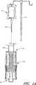
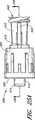
図1Aに、閉鎖位置にある閉鎖可能な雄ルアーコネクタ10の実施形態を示す。ルアーコネクタ10は、ポールスタンド11から懸架され、流体で満たされた重力供給式点滴バッグ9に取り付けられる。バッグ9の下端には、チューブ13の所定の部分が取り付けられる。チューブ13の反対側の端部はルアーコネクタ10の第1端部12に接続される。ルアーコネクタ10の第2端部14の内部にある閉鎖機構は、ルアーコネクタ10が閉鎖構成に保たれている限り、バッグ9の中に含まれる流体がチューブ13を通って流れ、ルアーコネクタ10から漏れ出すことを阻止する。 FIG. 1A shows an embodiment of a closeable
図1Bに、開放位置にあるコネクタ10を示す。流体は、コネクタ10の第1端部12に流入してコネクタ10の第2端部14から流出する。医療提供者は、閉鎖可能な雄ルアー10の第2端部を2本の指で掴み、チューブ13を他の2本の指で掴んで、これらの指を反対方向に徐々に動かして雄ルアーコネクタ10をこの形態に変えることができる。 FIG. 1B shows the
図1A及び図1Bに示す点滴供給システムは、患者との流体連通に容易に備えることができる。ほとんどの状況で、点滴バッグ9に初めて接続されたチューブ13は空気で充満している。図1Aに示すように、チューブ13の他端が閉鎖されたコネクタに接続されている場合には、空気が流出することができず、流体が点滴バッグからチューブ13に入ることができない。したがって、空気のすべてがルアー10から放出されて点滴バッグ9内の流体がチューブ13とコネクタ10を満たすまで、ルアーコネクタ10を手で開放位置に移動する。この操作は「呼び水」として公知である。流体管路とコネクタとに適正に呼び水を行うとすぐに、医療提供者はルアーコネクタ10の第2端部とチューブ
13とに加えられた反力を素早く解放することができ、ルアーコネクタ10の閉鎖機構はルアーコネクタ10を通る流体の流れを速やかに止めることができる。The infusion delivery system shown in FIGS. 1A and 1B can be readily provided for fluid communication with a patient. In most situations, the
ここで図1Cを参照すると、カテーテル17が患者の腕15に挿入されている。カテーテル17は、腕15の皮膚に侵入し、好ましくは患者の血流と流動的に結合される。また、カテーテル17は医療用雌コネクタ21に取り付けられた1本の医療用チューブ19に接続される。図1Cに示す医療用雌コネクタ21の例は、カリフォルニア州サンクレメンテ(San Clemente,California)のICUメディカル社(ICU Medical)社によって製造されたClave(登録商標)コネクタの1つの種類である。このタイプのコネクタについては、種々の実施形態が特許文献4に示され説明されており、同出願の全体を参照として本明細書に組み入れられている。本明細書に開示された雄ルアーの実施形態の多くは他のタイプの雌コネクタとともに使用可能であると考えられる。チューブ19、カテーテル17、及び雌コネクタ21には、標準的な手順に従って事前に流体で呼び水された。ルアーコネクタ10は前述のように呼び水されて、雌コネクタ21に係合される。以下にさらに詳しく説明するように、雄コネクタ10と雌コネクタ21とを係合すると、点滴バッグ9から患者に流体が流れる。雄コネクタ10と雌コネクタ21とを分離すると、雄コネクタ10の第2端部14からの流体の流出が再び阻止される。一般に、雌コネクタ21の開口からの流体の流出も阻止される。 Referring now to FIG. 1C, a catheter 17 has been inserted into the patient's arm 15. The catheter 17 penetrates the skin of the arm 15 and is preferably fluidly coupled to the patient's bloodstream. The catheter 17 is connected to one
図1A〜図1Cで示す実施形態を、以下にさらに詳しく説明する。本明細書に開示された他の実施形態の各々は、図示した流体システムと、これらの種々の変型システム及び代替システムにおいて使用することができる。さらに、本発明によるコネクタの種々の実施形態が多種多様なさらなる医療用流体システムにおいて使用可能であると考えられる。たとえば、開示されたコネクタは、血液、尿、又はインスリンなどの体液、滋養液、及び/又は化学療法による治療で使用される流体などの治療液の移送にも使用することができる。また、開示されたコネクタを使用して、その他様々な成分の流体移送システムを相互に連結することもできる。 The embodiment shown in FIGS. 1A-1C is described in further detail below. Each of the other embodiments disclosed herein can be used in the illustrated fluid system and in these various modification and alternative systems. Further, it is contemplated that various embodiments of the connector according to the present invention can be used in a wide variety of additional medical fluid systems. For example, the disclosed connector can also be used for the transfer of body fluids such as blood, urine, or insulin, nutrient fluids, and / or fluids used in chemotherapy treatments. The disclosed connector can also be used to interconnect various other component fluid transfer systems.
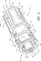
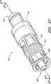
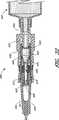
ここで図2〜図9を参照すると、図1A〜図1Cの閉鎖可能な雄ルアーがさらに詳しく示されている。図2に示すように、組み立てられたルアーコネクタ10は、ハウジング23、バルブ部材16、弾性部材18、及びシーリングリング20(図2では見えない)の4つの部分を備える。これらの部分を、図3〜図6に個別に示し、これらの図を参照してさらに詳しく説明する。ルアーコネクタ10はより多くの又はより少ない部分で構成することが可能であり、このような部分は異なる構成に組み合わせることもできる。 Referring now to FIGS. 2-9, the closable male luer of FIGS. 1A-1C is shown in greater detail. As shown in FIG. 2, the assembled
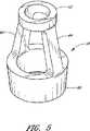
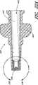
図3は、ルアーコネクタ10の他の部分を除いた状態のコネクタ10のハウジング23を示す。ハウジング23は、一般に、コネクタ10の第1端部12から、上部ハウジング34、及び中間部32、及びルアー先端22を通ってハウジング23の第2端部14まで延びる軸方向の通路28を有する管状の構造物である。一部の実施形態では、第1端部12からルアー先端22までのハウジング23の長さは、およそ1+1/8インチである。ハウジング23は、コネクタの重量と容積とが最小となるように、第1端部12から第2端部14まで約1+1/2インチ以下であることが好ましいが、必須ではない。ハウジング23は、具体的な用途に合わせて任意の適当な長さを有し得る。ルアー先端22は、シュラウド24によって包囲される基部25においてハウジング23の残部に連結する。ルアーコネクタ10の第2端部に向うルアー先端22の端部27は、シュラウドの縁29を超えて所定の距離を延在している。 FIG. 3 shows the
シュラウド24は、内壁上にねじ溝26を有していることが好ましく、このねじ溝26はコネクタ10を他の医療器具に可動にしっかり装着するのを助ける。他の実施形態では、シュラウド24はクイックリリース機構及びその他の手段を含む取り外し可能な接続を提供するために他の構造又は材料を含んでいてもよい。シュラウド24は、ユーザがハウジング23のシュラウド24を指でしっかり掴んで捻りやすくするために、外面に複数の凹所31を含む。凹所31は、指がコネクタ10から滑って離れないように上向きにテーパーが形成された側壁33を有する。各凹所31のコネクタ10の第1端部に向う末端では、ハウジング23の表面が凹所31の表面とほぼ共面であるが、各凹所31のコネクタ12の第2端部14に向う末端では、ハウジング23の表面が凹所31の表面からずれており、この表面よりも高い位置にあることが好ましい。この構成によって、コネクタ10の第2端部14の方向にハウジング23に沿ってコネクタ10を掴んだり捻ったりする位置に指をらくに滑らせることができる。指をいったん望ましい位置に置くと、凹所31においてコネクタ10の第2端部14方向の末端にあるテーパー付き壁33が、第2端部14の方向にさらに動かそうとする指の動きを阻止する。一連の凹所31はシュラウドのほぼ外面全体に広がっているため、コネクタ10の両側に指を当てると使用中のコネクタ10の向きに関係なく凹所31に触れることになる。 The
図示した実施形態では、先端22はテーパー状の外壁を有する。先端22の直径は基部25から第2端部27に向って次第に小さくなる。先端22はその第2端部27に孔を含む。ルアー先端22の基部25では、内部孔35(図8参照)がルアーコネクタ10の中間部32にある流体通路28の領域につながっている。ルアー先端の寸法は、ANSI規格などの適用規格及び/又は規制に適合するように製作し得る。 In the illustrated embodiment, the
ルアー先端22の内壁は、好ましくは、ルアー先端22によって包囲された流体通路28の軸の方向に内部で半径方向に広がるシェルフ30を含み、流体通路28を第2端部27の方が第2端部27に隣接する領域よりも狭くなるようにしている。図で示された実施形態では、コネクタ10の中心軸に向かって半径方向内側に面するシェルフ30の表面には、先端22の外面のテーパーと同様にテーパーが形成される(図8及び図9参照)。この構成では、シェルフ30の内径が第1端部に向う側から第2端部に向うシェルフ30の側の方向に狭くなる。以下でさらに詳しく説明するように、ルアー先端22のシェルフ30は、これにバルブ部材16の第2端部が当接するとき、コネクタ10を通る流体の流れを阻止及び/又は妨害するのを助ける。 The inner wall of the
ハウジング23の中間部32は、シュラウド24と上部ハウジング34の間に位置する。図で示すように、中間部32は、シュラウド24又は上部ハウジング34のいずれよりも外径が小さい。また、中間部32は、互いにハウジング23の反対側に配置された略長方形の2つの開口36を有している。コネクタ10を組み立てるとき、中間部32は弾性部材18の一部分でほぼ覆われている(たとえば、図2参照)。その結果、通常は、使用中に中間部32に指が触れることはない。このため、一部の使用形態では、中間部32に対して杷持可能な表面を使用する必要がない。したがって、中間部32は、ハウジング23の他のいずれの部分よりも外径を小さくし、表面を滑らかにし得る。 An
上部ハウジング34は、一般に、2つのギャップ38(図3には1つのみ図示)によって2つの壁部分45a、45bに分割される。上部ハウジング34は、形状と機能がシュラウド24にある凹所31に似た一連の凹所37を含んでいる。さらに、上部ハウジング34は、ギャップ38の中に延びる1つ又は複数の突出部43を備えていてもよい。組み立てられた形態では、突出部43は弾性部材18の一部分を壁部分45a、45bにあるギャップ38の間に保持する役割を果たす(図2参照)。一部の実施形態では、突出部43はコネクタの第1端部に向ってその端部で厚さが小さくなり、コネクタの第2端部に向ってその端部で厚さが大きくなるテーパーが形成される。突出部43のテーパーは、使用中に弾性部材18が曲って歪むことを見込んで弾性部材18の部分を望ましい位置に望ましい向きで挿入して保持するのに役立てられる。また、一組の突出部44をバルブ部材16の第2端部の方向に接触させてコネクタ12を開放位置に移動するときに、突出部43は、バルブ部材16が第1端部の方向に進み過ぎないようにする役割を果たす。突出部43のテーパーによって、組立て中に、バルブ部材16の突出部44は第2端部の方向に進みハウジング23の突出部43を通ってハウジング23に入る。使用中に指又は弾性部材18への裂傷、掻き傷、その他の損傷や刺激を避けるために、壁部分の各々にあるコネクタの第1端部に向うコーナー47に丸みをつけることが好ましい。 The upper housing 34 is generally divided into two
図3に示すように、上部ハウジング34の外面は下側シェルフ39を含み、シュラウド24の外面は組み立てられた形態でハウジング23の周りに弾性部材18の中心部分を保持する役割を果たすように構成されたシェルフ41を含んでいる(図2参照)。上部ハウジング34のシェルフ39は、弾性部材18がコネクタの第1端部の方向に滑らないようほぼ水平であることが好ましい。シュラウド24のシェルフ41は、コネクタ10を製作する際に弾性部材18がハウジング23に適切に位置するようテーパー状にすることが好ましい(図8参照)。 As shown in FIG. 3, the outer surface of the upper housing 34 includes a
ハウジング23は、複数の異なる材料のいずれかで構成し得る。一部の実施形態では、ハウジング23は、ポリカーボネート又はその他の高分子材料など、比較的硬質な材料で構成し得る。本実施形態のハウジング23及び/又はバルブ部材16、もしくは他の実施形態の構成部品は、バイヤー・マクロロン(Bayer Makrolon)などの疎水性材料、又は任意のその他の適当な材料で構成し得る。 The
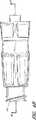
ここで図4Aを参照すると、雄ルアー10のバルブ部材16がコネクタ10の他の構成部品とは別に示されている。一部の実施形態では、バルブ部材16は、さらなる構造物で包囲された、バルブ部材16の第1端部48からその第2端部56まで外径が変化しながら延びる、流体通路52を備えている。第1端部48の近くでは、バルブ部材16と、流体通路52の対応する部分は、ここに挿入される標準径の医療用チューブの部分を収容するために比較的広くなっている。バルブ部材16の中間の近くでは、流体通路52の一部分を囲んでいる管40がバルブ部材16の第1端部に近い部分に取り付けられる。この管は、管40の少なくとも一部分に沿った2つのほぼ平行なストラット42に隣接している。管40は、円形断面もしくはその他適切な断面を有するものであってもよい。ストラット42は比較的薄くほぼ平板状であることが好ましい。各ストラット42の第1端部はバルブ部材16のほぼ中間部でバルブ部材16に結合し、各ストラットの第2端部はバルブ部材16の第2端部56に向って延びている。バルブ部材16の第2端部56は、ストラットの端部よりも先まで延びていることが好ましい。各ストラット42の内壁と管40の外壁との間には空間があることが好ましい。 Referring now to FIG. 4A, the
バルブ部材16の中間の近くからその第1端部48までの流体通路52は、その外面に沿って突出部44を有する比較的広い領域を備えている。突出部44は、バルブ部材16本体の両側に沿って縦方向に2つのチャネル46(図4Aには1つのみ図示)を形成している。一部の実施形態では、図で示すように、ストラット42がチャネル46から間隔を置いて周囲に配置されている。 The
バルブ部材16と管40の第1端部の近くには、円周チャネル48をバルブ部材16の本体の周囲に形成し得る。隆起タブ49はコネクタの第1端部の方向にチャネル48の縁に沿って形成することができ、一方、バルブ部材16の中間の隆起部はコネクタの第2端部の方向にチャネル48の縁を形成することができる。一部の実施形態では、隆起タブ49は、バルブ部材16の第1端部の周りに均等に広がらずに、一直径方向に互いに間隔を置いた2つの比較的大きい部を占めている。 Near the
バルブ部材16の構成に必要な材料の量は、この部分の外層に凹みを形成することによって減らすことができる。管40には、これを貫通する通路50を配置し得る。この通路50は、好ましくはバルブ部材16の第1端部における孔52からバルブ部材16の第2端部にほぼ隣接して定置された1対の孔50(図4Aには1つのみ図示)まで延びている。図で示した実施形態では、これらの孔50は形が一般に長方形である。コネクタの第2端部に近い管40の領域には1個のみの孔か、もしくは2個よりも多くの孔を形成することもでき、1個もしくは複数個の孔に対して他の形状を採用することもできる。たとえば、孔52には涙の形(たとえば、一端が狭く、他端が広い)を形成することができ、これによって製造の射出成形工程が簡単になる。さらに、一部の実施形態では、バルブ部材16を、流体経路のない構成とし、コネクタ10の第1端部と第2端部の間に流体の移送手段としてではなく、バルブ部材16の周りを流れる流体のブロッキングプランジャとして働かせることができる。 The amount of material required to construct the
バルブ部材16の管40は、その第2端部にフランジ部58を備えている。フランジ部58は、隣接する管40の部分よりも半径方向にさらに突き出ていることが好ましい。一部の実施形態では、フランジ部58を管40の他の部分と同じかほぼ同じ材料で形成し得る。フランジ部58は、バルブ部材16の第1端部から管40の第2端部の方向にテーパーが形成されていることが好ましい。一部の実施形態では、このテーパーが5°の角度で形成され、ハウジング23のシェルフ30の半径方向に内部で接する面のテーパーとほぼ同じテーパーを有している。これ以外の大きさのテーパーや無テーパーも使用可能である。 The
バルブ部材16は、図3のハウジング23と同様に、複数の異なる材料で構成し得る。このような材料の例として、ポリカーボネート又はその他の高分子材料が挙げられる。バルブ部材16は、ハウジング23とほぼ同じ長さか、もしくはそれよりもやや短くすることができる。たとえば、バルブ部材16の長さは、約1インチとし得る。一部の実施形態では、バルブ部材16の長さをハウジング23の長さよりも実質的に短くすることができる。バルブ部材16は、ハウジング23と同じ剛体材料で形成し得る。特定用途では、たとえば、半硬質、もしくはさらに可撓性の材料がバルブ部材16、特に管40の第2端部に向うフランジ部58に使用することが望ましい場合もある。 The
バルブ部材16は射出成形によって製造し得る。一部の実施形態では、成形過程での溶融プラスチックの分配を容易にするために少なくとも2つのゲートが使用される。1つのゲートをコネクタの第1端部に向うストラット42の端部と隆起タブ49の間のバルブ部材16の両側の一方に沿って設け得ることが好ましく、もう1つのゲートをバルブ部材16の孔52の近くに設け得ることが好ましい。ただし、ゲートの位置は固定せずに、バルブ部材16を射出成形するときはバルブ部材16の他の位置をゲート用に使用し得る。本実施形態もしくは他の実施形態のハウジング23とバルブ部材16の両方を同じ材料で構成すると、コネクタ10とその環境の間の熱膨張/収縮又は化学的相互作用によってコネクタ10の性能が劣化する可能性が小さくなる。 The
図で示した実施形態のバルブ部材16は図4Aに示すように構成されるが、他にも多くの構成が考えられる。一部の実施形態では、バルブ部材16は、その外面を比較的滑らかにすることができ、通路50を画定している管40を基本的に備えていてもよい。さらに他の実施形態では、種々の数のストラット42をバルブ部材16の両側に沿って配置し得る。 The
図4Bで示した実施形態から分かるように、バルブ部材16の第1端部の近くにある隆起タブ150は、シリンジなどの医療器具(図示せず)をバルブ部材16の第1端部に脱着可能に装着するために、ねじ山など外部係合面150を備えていてもよい。 As can be seen from the embodiment shown in FIG. 4B, a raised
図4Cで示した実施形態では、チャネル48は内面に沿ってさらにテーパーを形成し得る。チャネル48のテーパーは、バルブ部材16の第1端部180でサイズを比較的大きくし、バルブ部材の第2端部184に向ってサイズを小さくしてチャネル幅が減少するようになし得る。チャネル48の内部テーパーは、雄ルアーのテーパーと補完し合ってぴったり適合するようになし得る。このような内部テーパーは、医療用シリンジの規格など、ANSI規格及び/又は規制に適合させることができる。図で示した実施形態では、バルブ部材16の管40は、図4Aの実施形態のように、管40の壁を超えて外向き半径方向に延びるフランジ部58を有していない。代りに、管40の壁は、第2端部の領域の内部で半径方向にテーパーを形成している。ルアー先端22aの第2端部27aは、ルアー先端22aの第2端部27aの内面に沿って流体が漏れるおそれが少なくなる比較的小さい第2の断面部分170を有し得る。ルアー先端22aの第2端部27aの近くでは、比較的大きい断面領域160がコネクタの第2端部に向って、図4Cに示すような急峻な階段状遷移、又は緩やかなテーパー状遷移、又はその他の遷移などの多様な様相でより小さい断面部分170に遷移し得る。ルアー先端22aの第2端部27aにおける開口断面直径のサンプルには、約0.5mm、0.75mm、1.0mm、1.25mm、1.5mm、及び1.75mmなど、約2mm以下のものも含まれる。また、第2端部27aの開口直径は、0.4mm〜1.8mm、0.5mm〜1.5mm、及び0.5mm〜1.0mmの範囲とし得る。また、その他の直径には、内径、外径のいずれも列挙した範囲を適用し得る。さらに、バルブ部材16の第2端部は、ルアー先端22aの第2端部27aの開口内の空間を占有する適切なサイズに仕上げることができる。 In the embodiment shown in FIG. 4C, the channel 48 may further taper along the inner surface. The taper of the channel 48 may be relatively large in size at the
図4Bと図4Cに示すように、閉鎖可能な雄ルアーコネクタ10は、雌端部180と雄ルアー端部184の両方を有している。図1C(前記参照)の閉鎖可能な雌コネクタ21及び図10と図11の210(以下で詳しく説明)も、類似の外部構造を持つ他の標準雌コネクタと同様に、雌端部と雄端部の両方を有している。多くの実施形態では、このような雌コネクタに密閉又は他の流体障壁を利用して雄端部ではなく雌端部で流体の流れを妨げている。本明細書に示す閉鎖可能な雄ルアーコネクタの多くの実施形態では、雌端部にシール又は他の流体障壁を示していない。しかし、本明細書で開示された閉鎖可能な雄ルアーコネクタのいずれの雌端部も、閉鎖可能な雌端部を含むように構成し得る。たとえば、雌コネクタ21又は210、もしくは他の標準雌コネクタのずれかに関して流体イピーダンスを選択できる構造物を、本明細書で開示された閉鎖可能な雄ルアーコネクタのいずれかの雌端部内に含んで両方の端部で流体の流れを選択的に密閉又は妨害するコネクタを提供することができる。閉鎖可能な雌と雄の端部を備えたこの種の一部の実施形態では、特許文献4に示されるように、雌開口又はその近くに弾力性のある密閉要素を定置すると好都合な場合がある。密閉要素をこのように定置することによって、密閉要素表面及び/又は密閉要素と密閉要素に隣接するコネクタのハウジングとの間の領域内における残屑、細菌、殺菌剤又は他の不要な物質の有害な堆積を防止するために殺菌剤を使用してワイピングを行う前に雌開口を浄化することが可能である。 As shown in FIGS. 4B and 4C, the closeable
ここで図5を参照して、弾性部材18をさらに詳しく説明する。図で示した実施形態では、弾性部材18は2つの弾性部材64で分離された2つのリング60、62で形成されている。リング60、62及び/又は弾性部材64は、延ばしたときに復元力が作用するように構成された変形可能材料で作ることができる。このため、リング60、62を反対方向に引っ張っても弾性部材64はリング60、62を元の形状に戻すように作用する。 Here, the
弾性部材64はいくつかの弾性材料で構成し得る。一部の実施形態では、弾性部材64はシリコンゴム弾性材料から作られる。他の実施形態では、弾性部材64は形状記憶材料から作ることができる。さらに他の実施形態では、弾性部材64及び/又は弾性部材18は復元力を与えることができるバネ又は他の構造物を含んでいてもよい。 The
リング60、62もいくつかの材料で構成し得る。一部の実施形態では、リング60、62は、弾性部材64を備える材料と同じ変形可能弾性材料で構成される。このため、リング60、62は、各リング60、62を装着するハウジング23の適切な部分の周りに広がる直径にまで延びていてもよい。リング60、62の弾力は、各リング60、62をハウジング23の定位置に有効に保持するように作用することができる。他の実施形態では、リング60、62は、硬質又は半硬質材料で構成することができ、たとえば、ワンタッチで着脱可能な半円を備えていてもよい。一部の実施形態では、弾性部材18はバルブ部材16又はハウジング23に組み入れることができる。一部の実施形態では、他の構造及び/又は形態を採用して弾性部材18とは違った方法によるバルブ部材16とハウジング23の組合せを選択することが推奨される。 The
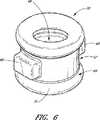
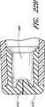
ここで図6を参照して、シーリング部20をさらに詳しく説明する。一部の実施形態では、シーリング部20は、ほぼ円筒形で、その中を貫通する孔66を有している。一部の実施形態では、シーリング部20は、正反対の位置で円筒部分の側壁から延びる1対の一般に長方形の突出部68をさらに備えている。突出部68は別の形状及び/又は位置を有してもよい。また、シーリング部20は、両端部にある直径の大きい2つのリング69で囲まれた一般に比較的小さい直径の中間部分67を有していてもよい。 Here, the sealing
シーリング部20は、複数の異なる材料で構成し得る。一部の実施形態では、シーリング部20はシリコンベースの変形可能材料70で作られる。シリコンベースの変形可能材料は、プラスチックとその他の硬質高分子材料からなる流体密の閉鎖を形成する材料に属する。シーリング部20は弾性部材18と同じ材料で作ることができる。 The sealing
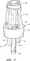
図7において、ある実施形態の雄ルアー10の特定構成部品を示す。図示のように、ハウジング23を省いてある。バルブ部材16、弾性部材18、及びシーリング部20はそれぞれ組み立てられた場所に示されている。 In FIG. 7, certain components of the
ここで、雄ルアー10の様々な部分間のいくつかの相互接続をさらに詳しく説明する。図示のように、弾性部材18の小さい方のリング62はバルブ部材16の円周チャネル54内に装着されている。一部の実施形態では、バルブ部材16の第1端部における隆起タブ49よりも大きい内径となるまで小さい方のリング62を広げることができる。小さい方のリング62が円形チャネル54周辺の所定位置に進むとこれを解放することができ、したがって図示のように円形チャネル54の周りがしっかりと包まれる。 Now, some interconnections between various parts of the
弾性部材18の大きい方のリング60はハウジング23(図2に示すように)の中間部32の周りに広がっており、これは小さい方のリング62に対して前述と同様に広げて定置し得る。この後、弾性部材18の弾性部材64は、弾性部材18の小さい方のリング62と大きい方のリング60の間で広げることができ、バルブ部材16のチャネル46に沿ってこの中に広げることが好ましい。いったんこれらのチャネル内に設置された弾性部材64は、事実上、チャネル外壁に沿った突出部44によって捕捉される。図2に示すように、弾性部材64はハウジング23の上部ハウジング34内のギャップ38に沿って広げることもできる。ギャップ38は、一般に図示の実施形態でチャネル46の上方に設けられる。これによって、弾性部材18はハウジング23とバルブ部材16を弾性結合し、バルブ部材16は引き入れられてハウジング23に係合する。 The
図7において、弾性部材18によって一部分が隠されているシーリング部20は、管40の周りにきちんと嵌合してバルブ部材16のストラット42の間に位置することが好ましい。 In FIG. 7, the sealing
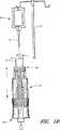
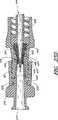
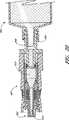
図8は、典型的な雌コネクタ92と隣り合う、本実施形態の雄ルアーの断面を示す。この断面図では、ハウジング23、バルブ部材16及びシーリング部20の間の相互結合と相互作用がさらに詳しく分かる。バルブ部材16はハウジング23内に定置されるように構成される。図示のように、バルブ部材16の管40は管腔28を通してその中に挿入し得る。一方、ストラット42はハウジング23の中間部32を通って長手方向に延びる対応スロットを通過するように構成される。組み立てられた形態では、ストラット42は2つの側面に沿って先端22に隣接し、管40は少なくとも一部分が先端22の内部に収容されている。突出部44は、ハウジング23の上部ハウジング34内に形成されたギャップ38の内部に捕らえられる。 FIG. 8 shows a cross section of the male luer of this embodiment adjacent to a typical
閉鎖機構56は、好ましくは雄ルアー10が雌コネクタ92に係合されていないときは必ず、外部環境との流体連通によって閉鎖可能な雄ルアー10を通って延びる流体通路を閉鎖するように構成される。図示の実施形態では、流体通路52は管腔28、及びバルブ部材16の通路54を備えている。図示の実施形態の閉鎖機構56は、管40のフランジ部分58と管腔28の隆起部29の内部テーパーとの両方を備えている。これら2つの表面が接触すると、雄ルアー10の第2端部20又はその近くで閉鎖が形成される。 The
管40の隆起部58と管腔28の隆起部29とが実質的に適合する内部のテーパー形成面は、雌コネクタ92を閉鎖する際に役立つ。相対的に流体密の閉鎖が形成されることが好ましい。隆起部29と58の係合はいくつかの別の方法で行うこともできる。一部の実施形態では、フランジ部58の材料と管腔28の隆起部29の材料は、互いにぴったり適合するように形成され、流体密の閉鎖を形成するために十分な適合材料で作られる。他の実施形態では、フランジ部58及び/又はバルブ部材16のさらなる部分は、管腔28の内面の輪郭により厳密に従う変形可能材料で構成することができ、管腔28にはテーパーが不要である。シーリング部20は、一部の実施形態では、流体が雄ルアーコネクタ10の内部から漏れないように構成される。バルブ部材16がハウジング23に係合すると、シーリング部20はハウジング23の中間部32と管40の間に位置する。流体が管40の外面に沿ってハウジング23の管腔28の内部に流れると、シーリング部20、特にシーリング部20のいずれかの端部のリング69によって中間部32を通る流体の流れは阻止される。 An internal tapered surface that substantially matches the raised
シーリング部20は、ハウジング23の中間部32の孔36に嵌合するように構成された突出部68(図6参照)によって、ハウジング23とバルブ部材16の間の定位置に保持されることが好ましい。突出部68はシーリング部20との正しい整合を維持する役割を果たす。 The sealing
ここで図8に示した実施形態を参照して、典型的な雌コネクタ92の構造をさらに詳しく説明する。雌コネクタ92は貫通する流体通路74を有する細長い本体72を備えていてもよく、雌コネクタ92はその末端近くに先端76を有していてもよい。一部の実施形態では、雌コネクタ92の先端76は、その外面に半径方向に広がる表面78が配置されている。雌コネクタ92の内部には流体管を定置し得る。流体管は、本明細書に開示されたコネクタ10と整合するすべての雌コネクタに含まれているわけではなくその必要もない。雌コネクタ92に近接する内面80に沿って、流体通路74はその直径が末端方向に減少するようにテーパーが形成されていることが好ましい。 The structure of a typical
図8に示すように、ハウジング23、バルブ部材16、弾性部材18、及びシーリング部20は、組み立てられた形態にあり、ここでは、閉鎖機構56がフランジ部58と管腔28の内部との間に閉鎖係合を形成している。さらに、シーリング部20は、バルブ部材16とハウジング23間の閉鎖係合にある。通路50の流体はバルブ部材16の管40の窓54を通って流れ得る。この位置において、窓54は先端22の内部と通流するが、外部環境とはまだ通流しない。管腔28は、その第2端部で閉鎖機構56によって、またその第1端部でシーリング部20によって閉鎖される。 As shown in FIG. 8, the
図8に示すように、バルブ部材16のストラット42はハウジング23のスロットを通って延びており、その端部はコネクタの第2端部に向うシュラウド24の端部に近い位置まで延びている。これらのストラット42は、雌コネクタ92が前進して閉鎖可能な雄ルアー10に係合するとき雌コネクタ92の近接端部84に係合するように構成される。 As shown in FIG. 8, the strut 42 of the
図8では、雄ルアーと雌ルアーは係合しない形態で示される。雄ルアー10と雌コネクタ92を係合するために、雌コネクタ92の半径方向に広がる表面78を雄ルアー10の雌ねじ26にねじ込む。 In FIG. 8, the male luer and the female luer are shown in a non-engaging form. In order to engage the
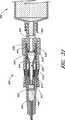
図9に示すように、雌コネクタ92の内面80のテーパーが先端22の対応するテーパー状の外面と隣接して位置すると2つのルアーは互いに螺合することができる。他の実施形態では、先端22の第2端部が雌コネクタ92の対応する表面(図示せず)と閉鎖を形成すると2つのルアーは螺合することができる。 As shown in FIG. 9, when the taper of the
雄ルアーコネクタ10と雌コネクタ92が互いに螺合する方向に移動すると、雌コネクタ92の先端に最も近い端部84がバルブ部材16のストラット42に接触する。雄ルアーコネクタ10と雌コネクタ92が螺合する方向にさらに移動すると、ストラット42、及びそれによってバルブ部材16が雌コネクタ92によって雄コネクタの第1端部の方向に移動してバルブ部材16をハウジング23に対して変位させる。したがって、フランジ部分58はハウジング23の先端22の第2端部から雄コネクタの第1端部の方向に移動する。これら2つのテーパー状表面が分離すると、バルブ部材16とハウジング23の間に空間が形成され、流体が孔30を通って雌コネクタ92の流体通路74に達し、この逆も同様である。内部流体管は、これを雌コネクタ92の一部の実施形態で使用すると、雌コネクタ92のハウジングがストラット42に接触して雄コネクタ19を開放する前にバルブ部材16の第2端部に接触する。一部の実施形態では、雌コネクタ92の先端の内面80が雄ルアー10の先端22の外面と閉鎖係合を形成するまで閉鎖が持続する。このため、雄ルアー10の通路50は外部環境と流体連通している必要がない。 When the
バルブ部材16がハウジング23に対して移動すると、弾性部材18の弾性部材64(図9に図示せず)が広がって復元力を与える。雌コネクタ92が雄ルアー10に係合している限り、この復元力はハウジング23の雌ねじ26に接触している雌コネクタ92の半径方向に広がる表面78によって阻止される可能性がある。しかし、雌コネクタ92が雄ルアー10から後退すると、弾性部材18はバルブ部材16のバルブ要素を管腔28との閉鎖係合に戻す。 When the
ハウジング23とバルブ部材16の間に相対的な移動があっても、シーリング部20は管40の外面と管腔28の内面との間の流体障壁を維持することが好ましい。一部の実施形態では、シーリング部20の位置は突出部68によって維持される。他の実施形態では、シーリング部20は、変形可能材料70の外面をハウジング23の管腔28の内面に接合することによって定置し得る。シーリング部20の固定には他の手段も使用することができる。 Even with relative movement between the
図9に示すように、開放された形態では、雌コネクタ92の流体通路74はバルブ部材16の通路50と流体連通することができる。それによって、流体は雄ルアー10に装着されたチューブ13からバルブ部材16の通路50に流れ、窓54を通って管腔28に流れ、先端22の第2端部にある孔30を通って管腔28から雌コネクタ92の流体通路74に流れ、この逆も同様である。シーリング部20によって、流体がハウジング23とバルブ部材16の間のギャップを通って雄ルアー10から漏れることは阻止される。また、流体密の閉鎖を、ハウジング23の先端22の対応するテーパーと雌コネクタ92の内面80との間で形成し得る。 As shown in FIG. 9, in the open configuration, the fluid passage 74 of the
図10を参照すると、コネクタ10が閉鎖可能な雌ルアーコネクタ210の隣に示されている。本明細書に示された実例の実施形態では、閉鎖可能な雌ルアーコネクタ210は、外側ハウジング213、空間212、流体通路218、1つ又は複数の孔215を有する流体管216、隣接面217を有する圧縮性シール要素214、及び螺合領域211を備えている。閉鎖可能な雌コネクタ210は、雄コネクタ10の第2端部56に隣接する近接端部を用いて定置される。閉鎖可能な雌コネクタ210の螺合領域211は、ANSI規格に適合する規格など、ルアーコネクタの標準サイズに適合させることができる。圧縮性シール要素214は、これに力が加えられたときにサイズが小さくなる防水性の弾力材料からなるものでもよい。流体管216は、ポリカーボネートプラスチックなど、シール要素214を圧縮するために十分な力を閉鎖可能な雌コネクタ210に加えたときに変形を阻止することのできる硬質材料からなるものでもよい。流体通路218は、流体管216を閉鎖可能な雌コネクタ210の第2端部219と流体連通させることができる。流体管216にある少なくとも1つの孔215を圧縮性シール要素214で密閉することによって、流体通路218が圧縮性シール要素214とハウジング213の内壁との間の空間212及び/又はハウジング213の外部と流体連通することを阻止することができる。孔215は、流体通路218と空間212の間で流体を適切な流速で通過させるのに適した小さなサイズに仕上げることができる。このようなサイズの孔215の1つは直径が約1mmであるが、正規でない形状と他のサイズも使用し得る。少なくとも約1mm又は約1mm〜3mm、もしくは約1mm以下の孔も使用し得る。コネクタ10は、流体が入ったチューブ13に係合することができる。 Referring to FIG. 10, the
図11を参照すると、コネクタ10は閉鎖可能な雌コネクタ210に螺合する。閉鎖可能な雌コネクタ210のねじ山領域211は、図示のように、コネクタ10、210に係合する雄コネクタ10の雌ねじ26に係合することができる。図示された係合では、ルアー先端22は圧縮性シール要素214を圧縮して閉鎖可能な雌コネクタ210の中に進入する。図から分かるように、ルアー先端22は圧縮性シール要素214の隣接面217で圧縮性シール要素214と接触する。コネクタ10、210を係合し、ねじ山領域26、211を係合するために加えられる力は、シール要素214を圧縮して流体管216内の孔215を露出させるのに十分である。シール要素214が圧縮されると、流体通路218はルアー先端22の内部空間と流体連通する。 Referring to FIG. 11, the
ルアー先端22が閉鎖可能な雌コネクタ210の中にさらに進入すると、流体管216は雄コネクタの第2端部に向ってバルブ部材16の端部に接触する。この接触とその後のルアー先端22の前進によって、バルブ部材16は雄コネクタの第1端部の方向に変位する。弾性部材18は、バルブ部材16の雄コネクタの第2端部の方向に閉鎖力を加える。その結果、雄コネクタの第2端部に向うバルブ部材16の先端は、通常、係合を通じて流体管216と接触を続ける。バルブ部材16が雄コネクタの第1端部の方向に移動すると、バルブ部材16のフランジ部58は孔30が貫通するハウジング23の内面から分離する。その結果、窓54が開いて閉鎖可能な雌コネクタ210と流体連通する。圧縮されたシール要素214は、流体がルアー先端22を越えて閉鎖可能な雌コネクタ210の内部に流入することを阻止する。この構成では、流体はバルブ部材16の端部のチューブ13から、雄コネクタの第2端部に方に向って管40に入り、窓54を通って管腔28の内部に入り、ルアー先端22の穴30を出て、閉鎖可能な雌コネクタ210の外側ハウジング213の内部に入り、流体管216の孔215に入り、流体管216の内部の流体チャネル217に流れる。したがって、コネクタ210の第2端部は閉鎖可能な雌コネクタ210の近接端部219と流体連通する。また、シーリング部20は、管40の外面と管腔28の内面との間の流体障壁を維持し、閉鎖可能な雌コネクタ210に向う流体の流れを制限することが好ましい。コネクタの第2端部に向うバルブ部材の表面に流体管216などの雌コネクタ部材が直接接触するときは、ストラット42が雌コネクタに係合してはならない。 As the
コネクタ10、210は、螺脱することができる。係合中、弾性部材18が及ぼす力によって、雄コネクタの第2端部に向うバルブ部材16の端部のフランジ部58がルアー先端22の内面に係合するようにバルブ部材16を案内して、コネクタ10を以前の係合状態に戻ることができる。同様に、圧縮性シールを構成する弾力材料は閉鎖位置で元の形状に戻り、隣接面217は閉鎖可能な雌コネクタ210の近接先端を密閉することができる。 The
ここで図12を参照すると、コネクタ10をシリンジ250に係合することができる。図12では、シリンジ250とコネクタ10が隣り合わせで表示されている。シリンジは雄ルアーコネクタ252、プランジャ258、容器260、及び使いやすい指掛部262を備えていてもよい。ルアーコネクタ252は、雌ねじが形成されたシュラウド254とシリンジルアー先端256をさらに備えていてもよい。図示されたコネクタ10の実施形態では、ねじ面150がバルブ部材16の第1端部の外面に配置されている。 Referring now to FIG. 12, the
ここで図13を参照すると、コネクタ10をシリンジ250に螺合することができる。シュラウド254は、コネクタの第1端部に向うバルブ部材の端部16に係合してコネクタ10をシリンジ250に結合することができる。シリンジ250の容器260は、バルブ部材16の内部の管40と流体連通させることができる。 Referring now to FIG. 13, the
図14を参照すると、図13で示された係合が断面図で示されている。シリンジ250は、シュラウド254とバルブ部材16のねじ面150との間の係合によってコネクタ10に螺合している。シリンジ250のルアー先端252はバルブ部材16の管40の中に延びている。シリンジの容器260は、ここでは容器260の中に流体が入った状態で示されており、バルブ部材16の内部と流体連通している。流体は、管40を通ってコネクタ10のルアー先端22の方向に進むことができる。図示された実施形態では、フランジ部58が管腔28の内面に接触しているため、流体はコネクタ10の雄ルアー先端22を出ることができない。したがって、コネクタの第2端部に向うハウジング23の先端にある孔30はバルブ部材16によって阻止される。シリンジ250とコネクタ10が図12に示された段階から図14に示された段階に遷移するためには、場合によってはバルブ部材16が一時的に開いて空気を放出する必要がある(以下にさらに詳しく説明するように)。 Referring to FIG. 14, the engagement shown in FIG. 13 is shown in cross section. The
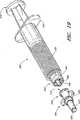
図15を参照すると、コネクタ10はシリンジ250とシース付き皮下注射針270に隣接してこれらの間に示されている。シリンジ250は、図12のシリンジと同様に、雄ルアーコネクタ252、プランジャ258、容器260、及び使いやすい指掛部262を備えていてもよい。ルアーコネクタ252は、雌ねじが形成されたシュラウド254とシリンジルアー先端256をさらに備えていてもよい。シース付き注射針270は、係合端の隆起タブ264付きのハウジング266と注射針268を備えていてもよい。 Referring to FIG. 15, the
図16を参照すると、シリンジ250とシース付き注射針270の両方に螺合したコネクタ10が示されている。コネクタ10のバルブ部材16のねじ面150は、シリンジ250のねじ付きシュラウド154に係合することができる。したがって、ルアー先端256はバルブ部材16の管40の中に突き出ていてもよい。同様に、隆起タブ264は、コネクタ10のシュラウド24の雌ねじ26に係合することができる。コネクタ10のルアー先端22は、注射針シースのハウジング266の中に突き出ていてもよい。 Referring to FIG. 16, the
図17に、図16に示した係合を断面図で示す。コネクタ10には、シリンジ250とシース付き注射針270が係合されている。シリンジ250は、コネクタ10のバルブ部材16のねじ面150に螺合されている。シース付き注射針270は、シュラウド24の雌ねじ26に螺合されている。 FIG. 17 is a sectional view showing the engagement shown in FIG. A
シリンジ250のルアー先端256は、バルブ部材16の管40の中に突き出ている。シリンジ250の容器260は、ルアー先端256を介してバルブ部材16の管40と流体連通している。 The
コネクタ10は、シース付き注射針270に係合している。シース付き注射針270のハウジング266は、その近接端部の近くに隆起タブ264を有している。隆起タブ264は、コネクタ10のシュラウド24の雌ねじ26に螺合している。ルアー先端22が注射針268のハウジング266に前進すると、ハウジング266の近接端部はバルブ部材16のストラット42と接触し得る。シース付き注射針270がコネクタ10に完全に係合すると、バルブ部材16は管腔28のテーパー付き内壁からフランジ部58を分離して流体がバルブ部分16の窓54から流出し得る程度の間隔だけ変位している。この後、流体は、ルアー先端22の端部にある孔30から流出してシース付き注射針270のハウジング266に入る。中空の注射針268は、流体をハウジング266の中から注射針268の末端に流出させることができる。シーリング部20は、管40の外面と管腔28の内面との間の流体障壁を維持して、管腔内の流体とルアー先端22の孔30に向う流れの方向とを制限することが好ましい。したがって、この段階では、シリンジ250は注射針268の先端と流体連通している。先に図13と図14に示したように、一部の実施形態では、部品がコネクタ10の第2端部14に係合していなければ、コネクタ10は、通常、流体をシリンジ250から流出させることができない。図15〜図17に示した部品はシース付き注射針270であるが、流体を流すことができかつ雌ルアーの係合部分を有する部品など、他の部品も使用することができる。 The
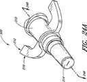
図18Aは閉鎖可能な雄ルアーの他の実施形態の透視図を示す。回転可能なコネクタ300は、ハウジング300、内部通路322、及びシール要素330からなる。ハウジングは、さらにルアー先端312、コネクタ300の第1端部におけるルアーレシーバ316、係合部分318、操作部分320、及び隆起部340からなる。シール要素330は、横方向にその面314に沿って開口350を有していてもよい。内部通路322は、ルアーレシーバ316からルアー先端312まで延びていてもよい。ハウジング310は、ポリカーボネートプラスチックなどの防水材料からなるものであってもよい。又はウジング310は、疎水性プラスチックからなるものでもよい。ハウジング310の構造に適した材料の他の例は、ガラス繊維強化GEバロックス420(GE Valox 420)又はポリプロピレンである。用途に応じてこの他の多くの材料も使用することができる。 FIG. 18A shows a perspective view of another embodiment of a closeable male luer. The
図示されたハウジング310は、その係合部分318で雄ルアーに螺合してルアーレシーバ316で雄ルアー先端を受け入れるように構成されている。レシーバ316は、ルアーレシーバに関するANSI規格に適合させることができる。図示された操作部分320は、ハウジング310の中心軸から半径方向に延びる2つのタブを有している。操作部分320は、ユーザがコネクタ300を掴んで回しやすいように構成される。 The illustrated
また、図示されたハウジング310は、その第2端部に閉鎖可能な雄ルアーを備えるように構成されている。第2端部のルアー先端312は、雄ルアー先端に関するANSI規格に従って構成し得る。ルアー先端は、隆起部340でハウジング310の本体と接合している。隆起部340は、ルアー先端312がルアーレシーバの中に進入し過ぎることを阻止するように構成される。又はウジング310は、隆起部340の後ろに凹部342を有していてもよい。また、ルアー先端312は、コネクタの第2端部に向う面314を有するシール要素330を有していてもよい。シール要素330は、シリコーンを無制限に含む防水性の弾力材料であってもよい。シールの構成材料の選択は当業者が行ってもよい。ルアー先端312には、隆起部340からその第2端部に近づくにつれて一方向に小さくなるテーパーが形成されていてもよい。 Also, the illustrated
また、シール要素330は、他の任意の部品に係合する前に、コネクタの第2端部に向う面314に開口350を有していてもよい。開口350は、ハウジング310の縦軸に対して横方向のスリットであってもよい。開口350は、面314の中心を横切っていてもよく、面314の別の位置にあってもよい。シール要素330は、ルアー先端312の第2端部全体を覆っていてもよく、その一部のみでもよい。シール要素330は、他の取付け方法の中でオーバーモルド工程によってハウジングに取り付けてもよい。このようなオーバーモルド工程では、ハウジング310を第1ステップで射出成形によって形成し、ついで第2ステップではハウジング310を型に再挿入し(又は、型に入れたままで)、適切なサイズに仕上げた成形ピン(図示せず)を、第2端部など、ハウジング310の幅広い方の端部から挿入することができる。この後、シリコーン材料を射出成形してシール要素330を形成し得る。他の実施形態では、シール要素330をハウジング310の中に接合、又は接着することもできる。 The sealing
図18Aに図示された実施形態から分かるように、ルアー先端312が他の部品に係合していないとき、シール要素330はハウジング310を通る流体の流れを阻止することができる。このため、雄ルアーコネクタ付きの流体を含有した部品(図示せず)をルアーレシーバ316に結合すると、コネクタ300を使用してそのルアー先端312を通る流体の流れを制御することができる。たとえば、シリンジなど、流体を含有した部品をコネクタ300に係合すると、流体が内部通路322を流れてコネクタ300のハウジング310を満たすことができるが、シール要素330は事実上ルアー先端312からの流体の流れを阻止することができる。流体が入る前にハウジングの内部空間が空気又はその他のガスで満たされている場合、流体が入り得る前に、コネクタ300を開いて空気又はその他のガスを逃す必要があることもある。一部の実施形態では、以下に詳しく説明するように、シール要素330の内面は開口350の広がりに対する抵抗が増すように構成することができ、これによって、内部通路322の流体(図示せず)からシール要素330に圧力がかかると流体を流出させることができる。したがって、コネクタ300が流体を含んだ部品の雄ルアーに装着されているとき他の部品がコネクタ300のルアー先端312に結合されていなければ、コネクタ300は流体を含んだ部品からの流体の流れを阻止する。 As can be seen from the embodiment illustrated in FIG. 18A, the
使用される一部のモードでは、シール要素330の面314にある開口350は、図示された位置で常時閉じており、ルアー先端312がカリフォルニア州サンクレメンテ(San Clemente,California)のICUメディカル社(ICU Medical)が販売するClave(登録商標)などの適当な雌コネクタと接触すると開く。図示されたこの構成の係合を以下に詳しく説明する。係合は、他の多くの方法と、クラーベ(Clave)コネクタ以外のコネクタを含む他の多くの構造物を用いて実現し得る。 In some modes used, the
図18Bは、図18Aに示したコネクタ300の断面図である。コネクタ300は、ルアーレシーバ316をルアー先端312に結合する内部通路322を有していてもよい。係合部分318は、雄ルアーコネクタの雌ねじが形成されたシュラウドを受け入れるように構成し得る(図19参照)。操作部分320は、図に示すように、内部通路322から離れて半径方向に延びていてもよい。シール要素330は、内部通路322の少なくとも一部に沿って延びていてもよく、コネクタ300の第2端部の少なくとも一部を横切って配置されていてもよい。シール要素330は、ルアー先端312の端部を越えて延びていてもよい。シール要素330は、ルアー先端312の端部でハウジング310にほぼ等しい断面積を有していてもよい。ルアー先端312とシール要素330が一般に円形である実施形態では、シール要素330の外径をルアー先端312の外径に等しくすることができる。シール要素330は円形に限らず(本明細書に開示された他のいかなる構造物も同様)、他の形状も採用し得る。他の実施形態では、シール要素330は、コネクタ300の第2端部に向うハウジング310の端部を越えて延びておらず、最大外部寸法をルアー先端312の内部寸法に等しくすることができる。シール要素330は閉鎖部分324を有していてもよい。閉鎖部分324は、コネクタ300のシール要素330を通して流体を流すことができるが、一般に、シール要素330の開口350を閉じるように付勢される。以下にさらに詳しく説明するように、閉鎖部分324の構造は、ルアー先端312が他の部品に係合されていないときに開口350からの流体(図示せず)の流出を阻止するように構成されてもよい。 18B is a cross-sectional view of
図18Bに示した断面図の詳細である図18Cから分かるように、シール要素330はコネクタ300の第2端部の面全体を含んでいてもよい。他の実施形態では、シール要素330はハウジング300を越えて延びていてはならない。内部通路322はコネクタ300の第2端部のシール要素まで延びていてもよい。 As can be seen from FIG. 18C, which is a detail of the cross-sectional view shown in FIG. 18B, the sealing
図19は、シリンジ360に隣接するコネクタ300の透視図を示す。前述のように、シリンジは、雄ルアーコネクタ362、流体容器370、プランジャ374、及び指掛部372を備えていてもよい。コネクタ300のルアーレシーバ316は、標準ルアーコネクタに係合する適切なサイズと形状のものとすることができ、シリンジ360のルアー先端364を受け入れるように定置される。シリンジ360のシュラウド364の雌ねじ368は、係合部分318と螺合するように正しく同心に配置される。こうして、レシーバ316は、ルアーコネクタ362に係合し、コネクタ300をシリンジ360に結合することができる。シリンジ360がコネクタ300に係合する前は、いかなる物理的構成要素によっても、容器370内部の流体がルアー先端364から流出することは免れない。 FIG. 19 shows a perspective view of the
ここで図20を参照すると、シリンジ360の螺合されたコネクタ300の透視図が示されている。コネクタ300は、接合、接着、溶剤、超音波溶接、エポキシ、締り嵌め、機械的結合、及び/又は単体構造など、他の多くの手段によってシリンジ360、又はその他の医療器具に結合することができる。レシーバ316(図示せず)は、シリンジ360のルアー先端364の少なくとも一部を含んでいる。ルアー先端364は、少なくとも部分的に内部通路322の中まで延びている。螺合部分318は、シリンジ360のシュラウド364の雌ねじ368に係合される。つぎに、容器370からの流体は、内部通路322を通ってコネクタ300のハウジング310内で自由に流れ得る。流体が入る前にハウジングの内部空間が空気又はその他のガスで満たされている場合は、流体が入り得る前にコネクタ300を開いて空気又はその他のガスを逃すことができる。場合によっては、コネクタ300のハウジング310を空気などのガスで満たしてもよい。流体がハウジング310に入る前に、コネクタを開いてガスを逃して流体を流す必要がある。シール要素330はコネクタ300からの流体の流出を阻止する。コネクタ300のルアー先端312を使用すると、コネクタ−シリンジ300、360の組合せを他の部品に結合して流体移送を制御することができる。また、コネクタ300は、コネクタのハウジング310をシリンジの流体供給端によって形成されるようにしてシリンジ360(図示せず)とともに一体型に形成することもできる。このコネクタ−シリンジの組合せを使用する際、結合目的に応じて、コネクタ300の雄ルアー先端312を、事実上、シリンジのルアー先端364に代用することができる。 Referring now to FIG. 20, a perspective view of the
化学療法薬剤など、ある種の薬剤は、接触毒であり、皮膚への暴露を避けることが望ましい。このような薬剤は、一般に図15と図16に図示したような皮下注射針付きのシリンジに蓄えられる。閉鎖可能な雄ルアーコネクタを使用しないある条件では、有毒な流体がシリンジから流出するおそれがある。注射針の付いたシリンジを重力の作用によって薬剤がシリンジ内に保持されるような向きにするなど、偶発的な流体の流出を回避する処置をとったとしても、薬剤が蒸発して皮下注射針から気体の状態で漏れ出すおそれがある。シリンジと皮下注射針の間に閉鎖可能な雄ルアーを使用すると、液体と気体の両状態にある薬剤の制御されないままの流れが阻止される。したがって、こうした有毒薬剤への偶発的な暴露の危険性が最小限に抑えられる。 Certain drugs, such as chemotherapeutic drugs, are contact poisons and it is desirable to avoid exposure to the skin. Such a medicine is generally stored in a syringe with a hypodermic needle as shown in FIGS. Under certain conditions where a closable male luer connector is not used, toxic fluid may escape from the syringe. Even if you take measures to avoid accidental fluid outflow, such as the orientation of the syringe with the injection needle so that the drug is held in the syringe by the action of gravity, the drug will evaporate and the hypodermic needle There is a risk of leaking in a gaseous state. Using a closable male luer between the syringe and hypodermic needle prevents uncontrolled flow of the drug in both liquid and gas states. Therefore, the risk of accidental exposure to such toxic drugs is minimized.
ここで図21を参照すると、他の実施形態における閉鎖可能な雄ルアーコネクタ300が示されており、この実施形態では、雌ねじが形成されたシュラウド380がハウジング310に配置されている。シュラウド380は、入込み部342(図18Aで見られる)の近くにおいてハウジング310を少なくとも部分的もしくは全体的に取り囲んでいる。一部の実施形態では、シュラウド380はコネクタ300に装着されておらず、コネクタ330の縦軸の周りに自由に回転可能である。隆起部340(図18Aで見られる)は、コネクタ300のルアー先端312方向へのシュラウド380の移動を阻止することができる。さらに、コネクタ300の操作部分320は、ルアーレシーバ316方向へのシュラウド380の移動を阻止することができる。シュラウド380には、ルアーコネクタに関するANSI仕様と調和したねじを形成し得る。シュラウド380は、ルアー先端312によってコネクタ300とその他の部品(図示せず)の間の結合部を形成する際に役立つ。 Referring now to FIG. 21, there is shown a closeable
ここで図22Aを参照すると、連続的なテーパー状の内部通路402を備えた閉鎖可能な雄ルアーコネクタ400の断面が示されている。ハウジング404のテーパー状の内部通路402によって種々の射出成形による製造法が可能になる。たとえば、テーパーがルアーレシーバ406の端部でより広くなると、成形ピンをこれに対応した方法でテーパーに形成して、内部通路402の壁にぴったり嵌合させ、図18Bに示されたシールよりも短いシール408を製作することができる。 Referring now to FIG. 22A, a cross section of a closeable
図22Bを参照すると、図示された実施形態におけるシール408は、図18Bの閉鎖部分324のシールに似た閉鎖部分412を有している。さらに、シール408の内面は、内部通路402内の流体(図示せず)がシール408を圧迫すると開口410からの流体の流出に対する抵抗が増加するように構成し得る。閉鎖部分412の内面には、このような流体が圧迫すると開口410が一層しっかり閉じるように傾斜面を持たせることができる。 Referring to FIG. 22B, the
図23Aを参照すると、図22Aのコネクタ400の他の実施形態の側面図が示されている。雌ねじが形成されたシュラウド420がハウジング404の外面の周りに配置されている。 Referring to FIG. 23A, a side view of another embodiment of the
図23Bから分かるように、ハウジング404は、ルアー先端416に向うシュラウド420の軸方向の移動を阻止する隆起部424を有していてもよい。又はウジング404は、コネクタ400の縦軸から外に向って半径方向に延びる操作部分418を有していてもよい。又はウジング404は、ルアーレシーバ414からシール要素430まで延びる内部通路428を有している。操作部分418は、シュラウドがコネクタ400のルアーレシーバ414に向う移動を阻止することができる。さらに、操作部分418は、ユーザがコネクタ400を回しているときに自分の指を置く好都合な位置にあってよい。さらに、コネクタ400の入込み部426があってもよい。入込み部426は、隆起部424又は操作部分418の外径よりも小さい外径のコネクタ400の一部であってもよい。シュラウド420は、シュラウド420の狭い部分が入込み部426の周りでコネクタ400を取り囲むようにコネクタ400に配置し得る。シュラウド420は、ハウジング404に固定せずに、したがって自在に回転し得る。シュラウドの雌ねじ422は、ルアーコネクタに関するANSI規格に適合させてルアー先端416が他の部品(図示せず)の雌コネクタに係合する際にシュラウドを役立てることができる。 As can be seen from FIG. 23B, the housing 404 may have a
図23Cは、図23Bの閉鎖可能な雄ルアーコネクタ400を、カリフォルニア州サンクレメンテ(San Clemente,California)のICUメディカル社(ICU Medical)が販売するClave(登録商標)コネクタなど、適当な雌コネクタ450に近接させて示す。雌コネクタ450は図10に示したものに類似している。 FIG. 23C replaces the closable
図23Dは、雄ルアーコネクタ400と雌コネクタ450の間の係合を示す。シュラウド420の雌ねじは、雌コネクタ450のねじ領域451に係合させることができる。雄ルアーコネクタ400のルアー先端416は、圧縮性シール454を圧縮して雌コネクタ450に進入することができる。雄コネクタ400が進入すると、雌コネクタ450の静止した流体管456は、雄コネクタ400のシール要素430の中にある開口448に侵入することができる。流体管456は、孔455が雄コネクタ400の内部通路428の中に進入する程度の奥まで雄コネクタ400に進入し得る。雌コネクタ450の孔455が雄コネクタの内部通路428内に配置されると、流体は雄コネクタ400のルアーレシーバ414から雄コネクタ400の内部通路428を通って雌コネクタ450の流体管456の孔455に流れ得る。この後、流体は孔455を通って雌コネクタ450の流体管458に流れ得る。こうして、雄コネクタ400と雌コネクタ450が係合しているときは、流体は雄コネクタ400の第1端部から雌コネクタ450の末端に流れ得る。コネクタ400、450を螺脱すると、流体管456は内部通路428から後退し、シール要素430が閉じ、それによって雄コネクタを通る流体の流れが阻止される。さらに、雌コネクタ450の圧縮性シール411は、その当初の状態に戻り、流体管456の孔455を通る流れを阻止する。 FIG. 23D shows the engagement between the
ここで図24Aを参照すると、閉鎖可能な雄ルアーコネクタ500が透視図に示されている。コネクタ500はハウジング510とシール514を有している。ハウジングは操作部分512からなる。この典型的な例示では、操作部分512はウィング516を含んでいる。ウィング516は、コネクタ500のハウジング510を掴んで回転する場所をユーザに提供するように構成されている。 Referring now to FIG. 24A, a closeable
ここで図24Bを参照すると、図23Aのコネクタ500が断面で示されている。ウィング516は、コネクタ500の縦軸から外向きに、かつコネクタのルアーレシーバ518に向って延びているものとして示されている。ハウジング510の内部通路520は、図22Aのコネクタ400の実施形態で説明したように、連続的なテーパーを有している。 Referring now to FIG. 24B, the
図25Aを参照すると、閉鎖可能な雄ルアーコネクタ600の側面図が示されている。コネクタ600は、ハウジング610、シール要素614、及びシュラウド620を有している。ハウジングは、内部通路640、ルアー先端612、及び操作部分616を備えている。操作部分は、図24Aに示したように、2つのウィング630を含むように構成し得る。シュラウドは雌ねじ622を有していてもよく、この雌ねじはルアーコネクタに関するANSI仕様に適合するように構成し得る。シール要素614は、係合されないときに閉じるように付勢され得る。 Referring to FIG. 25A, a side view of a closeable
ここで図25Bを参照すると、図25Aのコネクタ600の断面図が示されている。シュラウド620は、ハウジング610の入込み部652でハウジング610を取り囲んでいてもよい。隆起部650はコネクタ600の第2端部に向うシュラウド620の移動を阻止することができるが、操作部分616はコネクタ600の第1端部に向うシュラウドの移動を阻止することができる。シュラウド620の雌ねじ622は、ルアー先端612とともに、他の部品(図示せず)との係合に使用することができる。連続的なテーパーを形成する内部通路640は、図22Aに関して説明したように、射出成形に好都合な特質を有している。 Referring now to FIG. 25B, a cross-sectional view of the
図26Aを参照すると、閉鎖可能な雄ルアー700及び柔軟に結合された雌ルアーコネクタ750を含む、閉鎖可能な雄ルアーアセンブリ725の透視図が示されている。閉鎖可能な雄ルアー700は、この用途において説明するかなりの数の態様と特徴を実施することができる。雌ルアーコネクタ750は、標準雄ルアーコネクタ(図示せず)を受け入れるように構成される。雌ルアーコネクタ750は、雄ルアーコネクタ700に隣接させて設置され、これに柔軟に結合される。雌ルアーコネクタ750は、内部通路752、ルアーレシーバ754、及び係合部分756を備えている。内部通路752は、ルアーレシーバ754を閉鎖可能な雄ルアーコネクタ700の内部通路と流体連通させる。閉鎖可能な雄ルアーコネクタ700は、フレキシブル部分760によって雌ルアーコネクタ750に装着し得る。一部の実施形態では、こうしたフレキシブル部分760は、アコーディオン様の弾力材料のフレキシブル部分を含んでいてもよい。他の実施形態では、まっすぐでフレキシブルな材料を使うことができる。他の実施形態では、閉鎖可能な雄ルアー700と雌ルアー750を結合するために外部のフレキシブル部分とフレキシブルチューブの両方を使用することができる。 Referring to FIG. 26A, a perspective view of a closeable
ユーザは、フレキシブル部分752によって、アセンブリ725の雌コネクタ750の向きを変えて閉鎖可能な雄ルアーコネクタ700の姿勢と異なる姿勢となし得る。一例を挙げると、閉鎖可能な雄ルアー700は患者の腕に静止状態に保つことができるが、雌コネクタ750はシリンジ又は他の部品(図示せず)と結合しやすくするために腕から離して傾ける。閉鎖可能な雄ルアー700を雌ルアーコネクタ750に屈撓自在に結合することによって、雌ルアーコネクタ750の移動によって生じるモーメントは、アセンブリ725の2つの部品間の一点で受け入れられ、閉鎖可能な雄ルアーコネクタ700に装着された他の部品(図示せず)には伝わりにくい。このような部品として、点滴部位を挙げることができ、この場合、結合角度が患者にとって有害なこともある。さらに、このモーメントによって、管腔28の内部からの管40の先端が曲げにくかったり、及び/又は外れにくかったりすることになる(たとえば、図28参照)。 The
図26Bは、閉鎖可能な雄ルアーコネクタ825と屈撓自在に結合された雌ルアーコネクタ850を備える閉鎖可能な雄ルアーアセンブリ800の他の実施形態を示す。コネクタ825、850とこれらの部品は、図26に示した実施形態と多くの点で類似しており、前述したかなりの数の態様と特徴を具現することができる。閉鎖可能な雄ルアーコネクタ825と雌ルアーコネクタ850は、結合部材860によって屈撓自在に結合される。結合部材860によって、コネクタ825、850は流体連通される。本明細書に図示された結合部材860は、アコーディオン形のプラスチック管路を備えている。結合部材860は、閉鎖可能な雄コネクタ825と雌ルアーコネクタ850が種々の角度方向で定置されるように構成される。一例では、閉鎖可能な雄ルアーコネクタ825は静止状態を保つことができるが、雌ルアーコネクタ850は閉鎖可能な雄ルアーコネクタ825に対して斜めに定置させることができる。他の例では、雌ルアーコネクタ850は静止状態を保つことができるが、閉鎖可能な雄ルアーコネクタ825は雌ルアーコネクタ850に対して斜めに定置させることができる。さらに他の例では、閉鎖可能な雄ルアーコネクタ825と雌ルアーコネクタ850をともに斜めに設置することができる。 FIG. 26B shows another embodiment of a closeable
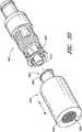
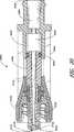
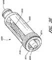
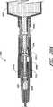
図27〜図32は、雄端部902と雌端部904を備えた閉鎖可能な雄ルアーコネクタ900の他の実施形態を示す。ある点で、コネクタ900の構造とアセンブリが本明細書に開示されて図示された他の実施形態に類似している。たとえば、コネクタ900は外側ハウジング906、シュラウド908、弾性部材910、内部バルブ部材912、及び内部シーリング部914を含んでいてもよい。本明細書に開示された各実施形態の説明、例示、及び特徴のすべては、本明細書に開示された他の実施形態にも適用可能である。以下に説明するように、コネクタ900は、雄端部902が閉鎖する過程で雄端部902から流体が滴る可能性を阻止又は最小化する際に有効であり得る。 FIGS. 27-32 illustrate another embodiment of a closeable
図28と図29に示すように、バルブ部材912は、断面積が変化する内部の流体通路916を有していてもよい。一部の実施形態では、バルブ部材912が内部通路を有しておらずに流体がバルブ部材912の周りを流れる。図示のように、一般にハウジング906の雄端部902内に定置された通路916の領域918の断面積は比較的狭くてもよく、一般にコネクタ900の中間に定置された通路916の領域920の断面積は図示のように広くてテーパー状の壁を有していてもよく、雌端部904の近くに定置された通路916の領域922は第2の領域920よりも大きい内部容積を有していてもよく、通路916の領域924は狭い開口926を経由して領域922に結合されていてもよく、領域928は領域924に結合されていてもよい。一部の実施形態では、領域928を狭い開口(図示せず)を介して領域924に結合することができる。一部の実施形態では、コネクタ900はコネクタ900を開放しやすくするために1つ以上のストラット921を備えていてもよい。 As shown in FIGS. 28 and 29, the
前述のように、ハウジング906の領域928と雌端部904は、コネクタ21、210の閉じしている雌端部の1個以上の部品(及び/又は他のタイプの閉じている雌コネクタの部品)を備えるように構成して、コネクタ910の雌端部904を選択的に開閉して流体が流れるようになし得る。 As described above, the
内部管路932は、内部の流体通路916の領域924を部分的又は完全に包囲していてもよい。内部管路932は基部934に固定することができ、基部934は一方の側で雌端部904に、また他方の側で中間部936に固定することができる。図示された実施形態では、基部934の外周は、ハウシング906の外周まで延びているが、他の多くの方法で構成し得る。中間部936はハウジング906の残部に固定し得る。雄端部902から離れたバルブ部材の末端で、内部管路938は流体通路916の領域922を包囲していてもよい。図示された実施形態では、バルブ部材の内部管路938は、領域924を包囲する内部管路932よりも断面積と内部容積が大きい。シール要素940を内部管路932、938の間の界面領域に定置すると、このような界面での通路916からの流体の漏れを阻止又は最小化し得ると同時に内部管路932、938間の相対的な軸方向の移動が可能になる。一部の実施形態では、内部管路932、938は剛性があり、通常の使用状態では撓みや曲りが生じない。一部の実施形態では、外側ハウジング部分906、908、934、及び936は、1個の接触ハウジングに成形される。他の実施形態では、これらは個別に成形され、後で互いに接合されてハウジングに形成される。
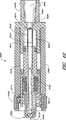
図30に示すように、コネクタ900の雌端部904は、シリンジ942など、他の医療器具の雄部分944に結合することができる。本明細書に開示されたこの実施形態及び他のすべての実施形態において、様々な他のタイプの医療器具を開示されたコネクタに装着することができる。図30に示した構成では、コネクタ900とシリンジ942は、化学療法薬剤などの流体で満たされている。流体は、通常の状態でコネクタ900から漏れることはない。一方の側ではバルブ部材912と雄端部902の間の界面によって、また他方の側では医療器具942内の流体圧と構造によって漏れが妨げられるからである。 As shown in FIG. 30, the
図31に示すように、コネクタ900を他の医療器具(プラスチック点滴チューブの雌コネクタハウジング946など)に装着した際にバルブ部材912が圧迫されて雄端部902から離れると、内部管路938は雌端部904の方向に移動し、内部管路932の少なくとも一部分と重なる。この後、流体はコネクタ900を経由して医療器具942、946の間を流れることができる。この第2の開放された構成もしくは位置では、領域922が第1の閉鎖された構成もしくは位置にあったときよりも小さくなる(図30参照)。他方、領域918、920、及び928は、通常、ほぼ同じ大きさのままである。バルブ部材912が内部流路を有さない場合を含む一部の実施形態では、コネクタ900内の容積が変化する領域は、バルブ部材912を通る流体の流れを案内せずに滑動係合する重なり構造によって得られる。たとえば、バルブ部材が硬質であれば、内部管路932の中に進入することも同932から後退することも可能であり、適当な開口(たとえば、内部管路932又は基部934)によって、流体はハウジング906を通って雄端部902に流れる。バルブ部材912が内部流路を有さない場合を含む一部の実施形態では、バルブ部材は内部管路932に上に重ねることが可能なスリーブと、ハウジング906から雄端部902まで流体を流すことが可能な適当な開口(たとえば、内部管路932又は基部934)とを備えていてもよい。 As shown in FIG. 31, when the
一部の実施形態では、医療器具946をコネクタ900から離脱すると、バルブ部材912が弾性要素910の付勢力を受けてハウジング906内で雄端部の方向に移動して雄端部902が自動的に閉じることがある。ある状況では、流体通路内でバルブ部材が移動すると、雄端部内の少量の流体が雄の開口を通ってコネクタの外部に押し出され、その結果バルブの閉鎖によって流体の滴下が生じる可能性がある。しかし、図示された実施形態では、こうした滴下は一般に阻止又は最小化される。 In some embodiments, when the medical device 946 is removed from the
図32に示すように、医療器具946とバルブ部材912が矢印950の方向に進むと、内部管路932、938間の重なり領域が減少して流体通路916の領域922の容積が増加することがある。領域922の容積は最終的に閉鎖形態における当初の適切な容積に戻る(図30参照)。雄ルアーの閉鎖中に領域922の容積が膨張すると、流体が通路916内の他の場所から領域922の中に移動させられる。 As shown in FIG. 32, when the medical instrument 946 and the
一部の実施形態では、領域922で増大する空洞を領域922とシリンジなどの医療器具942との間の流体によって満たすことができない。このような流体の移動は医療器具942(シリンジ内のステムシールなど、図示せず)の構造物によって阻止されるからである。さらに、図32に示すような一部の実施形態では、領域922と雌コネクタ904の端部との間の開口926は、領域922、920と雄ルアー内の流体通路916の残部との間の開口952、954よりも実質的に小さい。この形態では、雄端部902内の流体抵抗は雌端部904内の流体抵抗よりも小さくなる可能性がある。一部の実施形態では、開口926の断面積が開口954の断面積の1/2以下である。一部の実施形態では、開口926の断面積が開口954の断面積の1/4以下である。一部の実施形態では、開口926の断面積が開口954の断面積の1/5以下である。この形態によって、流体は雌端部904からよりもむしろ雄端部902からコネクタに流れやすくなる。 In some embodiments, the cavity that grows in
領域922に空洞があると、バルブ部材912と雄端部902の内壁との間の流体は、雄開口から押し出されるのではなく、コネクタ900本体内で領域922の方向に引き戻される。コネクタ900が閉じると、コネクタ900内部の容積の増加によって、開口948から流体が放出されようとするのではなくむしろ引込まれようとする。図示された実施形態では、これは、領域922の断面積を開口948の断面積よりも実質的に大きくすることによって一部分は実現される。バルブ部材912が閉鎖位置に移動するとき、領域922の容積は開口948の容積の減少よりも速く増加する。一部の実施形態では、重なりのある内部管路938、932の硬質な壁によって長時間の繰返し動作と最小限の損耗での使用を維持し得る。重なりのある内部管路938、932の壁は、一般に変形したりぐらついたりしないものの、閉鎖中にコネクタの内側に発生する空洞の大きさに影響する可能性がある。さらに、重なりのある内部管路938、932の壁は、一般に、コネクタ内の比較的高い流体圧力で膨らんだり座屈したりせず、また、一般に、ほとんどの条件下においてハウジング906の内部空洞内でバルブ部材912に心ずれを起すこともない。 When there is a cavity in
本明細書に開示された閉鎖可能な雄ルアーコネクタの一部の実施形態では、コネクタが装着された1つ以上の医療器具に空気を送り込まずにコネクタに「呼び水」する(すなわち、コネクタの内部の空気を流体で置換する)ことは困難な場合がある。このような実施形態では、コネクタの雄端部に個別に呼び水キャップを装着することができる。呼び水キャップは多様な方法で構成し得る。 In some embodiments of the closable male luer connector disclosed herein, the connector is “primed” (ie, the interior of the connector) without sending air to one or more medical devices to which the connector is attached. It may be difficult to replace the air with a fluid. In such an embodiment, a priming cap can be individually attached to the male end of the connector. The priming cap can be constructed in various ways.
図33は、閉鎖可能な雄ルアーコネクタ900に使用可能な呼び水キャップ956の一例を示す。適当に構成された呼び水キャップは、本明細書に開示された雄ルアーコネクタのどの実施形態でも使用することができる。一部の実施形態では、呼び水キャップ956は閉鎖可能な雄ルアーコネクタ900を開く構造(バルブ部材912を押圧する硬質の内部管路(図示せず)、又はシュラウド908の内側にストラットを当接するように構成されたハウジング壁960を備える雌端部962など)を備えていて、流体を閉鎖可能な雄ルアーコネクタ900の内側から逃すことができる。また、呼び水キャップ956は、開放された雄ルアーコネクタ900からの流体が通過することのできる内部流体通路(図示せず)を含んでいてもよい。流体通路は出口孔964に通じていてもよい。また、呼び水キャップは、流出する空気を通すが進入する液体を通さないフィルタ958を含んでいてもよい。図示された実施形態では、フィルタ958は出口孔964内に定置されている。このため、空気は雄ルアーコネクタ900から呼び水キャップ956を介して出口孔964の外に引き抜くことができるが、液体は、通常、雄ルアーコネクタ900と呼び水キャップ956の内部に残る。呼び水が終了すると、呼び水キャップ956を取り外して廃棄することができ、これによって閉鎖可能な雄ルアーコネクタ900を自動的に閉じて、別の医療器具を閉鎖可能な雄ルアーコネクタ900に装着し得る。この他にも多くの構造と形態の呼び水キャップを使用することができる。 FIG. 33 shows an example of a
図34と図35は、雄端部902a、ハウジング906a、雌端部904a、弾性部材910a、及びストラット921aを備えた閉鎖可能な雄ルアーコネクタ900aの他の実施形態を示す。図35に示すように、雄端部902aの先端に近いバルブ部材912aの端部913aは、雄端部902aの先端の内側に当接するように構成された第2表面917aよりも断面積が大きい第1表面915aを有していてもよい。この形態は、雄端部902aを通る雄ルアーコネクタ900aからの漏れに対してさらに耐性のある界面を作る際に役立つことができる。図35の実施形態では、内部管路938aは断面が内部管路932aよりも小さい。管路932a、938aの間の相対モーメントは、図27〜図32に示した実施形態におけるように、領域922aの容積変化を生じる。弾力シール940aは、管路932a、938a間の界面における流体の漏れを阻止又は最小化する。閉鎖可能な雄ルアーコネクタ900aが図示のように第1の閉鎖位置にあるとき、領域922aの容積は閉鎖可能な雄ルアーコネクタ900aが第2の開放位置にあるときよりも大きい。内部通路916aは、通路916aが比較的に一定の断面積を維持するようにまっすぐな壁を有していてもよい。一部の実施形態では、通路916aの壁はテーパーを含んでいてもよい。閉鎖可能な雄ルアーコネクタ900aは、多くの点で図27〜図32の閉鎖可能な雄ルアーコネクタ900と同様に機能する。 34 and 35 show another embodiment of a closeable male luer connector 900a comprising a male end 902a, a housing 906a, a female end 904a, an elastic member 910a, and a
図36と図37は、雄端部902b、ハウジング906b、雌端部904b、及び弾性部材910bを備えた閉鎖可能な雄ルアーコネクタ900bの他の実施形態を示す。また、この実施形態は、雄ルアーコネクタを手動で開閉するためのアクチュエータ925bも含んでいる。バネ、ボタン、レバー、及びその他の構造物を採用したものなど、多くの様々なタイプの手動アクチュエータを使用することができる。図示された実施形態では、バルブ部材912bは、指を触れて雄端部902b又は雌端部904bのいずれかの方向に前進させることが可能な少なくとも1つの側面927bを含んでいる。図示された実施形態では、バルブ部材912bはシュラウド908b内にストラット921bを備えている。したがって、側面927bを雄端部902bの方向に移動したとき雄ルアーコネクタ900bがその雄端部902bで他の医療器具に装着されていなければ、雄ルアーコネクタ900bを閉じることができる。側面927bを雌端部904bの方向に移動すると、他の医療器具がコネクタ900bの雄端部902bにまだ装着されていなくても雄ルアーコネクタ900bを開くことができる。図36に示すように、アクチュエータ925bの外面を鋸歯状にするか、さもなければ織り込んで指が滑らないようにし、アクチュエータ925bの外面をハウジング906bの外周のわずかに下に定置し、特にコネクタ900bの取付け又はその他の移動の際にコネクタ900bを誤って開閉しないようになし得る。一部の実施形態では、バルブ部材912bはシュラウド908b内にストラットを備えてはならない。 36 and 37 show another embodiment of a closeable male luer connector 900b with a male end 902b, a housing 906b, a female end 904b, and an elastic member 910b. This embodiment also includes an actuator 925b for manually opening and closing the male luer connector. Many different types of manual actuators can be used, such as those employing springs, buttons, levers, and other structures. In the illustrated embodiment, the
コネクタ900bを手動で開閉するアクチュエータ925bなどの構造は、閉鎖可能な雄ルアーコネクタ900bに呼び水する際に一部の用途で特に好都合な場合がある。これは、コネクタ900bを別の用具に装着する前にコネクタ900b内部の空気を環境に放出しながらコネクタ900bを開くことができる(そうでなければ、放出された空気はこうした他の用具に送り込まれることになる)。コネクタ900bの開閉に手動手段が用意されているときは、呼び水キャップは必ずしも必要でない。 Structures such as an
図38と図39Aは、雄端部902c、ハウジング906c、雌端部904c、及び弾性部材910cを備えた閉鎖可能な雄ルアーコネクタ900cの他の実施形態を示す。この実施形態は、流体の流れを妨害又は一時中断するための内部構造物も備えている。弾力のあるカバー933cは、一般に、領域922c内に定置される。弾力のあるカバー933cは、図示された実施形態では一般に平坦である前面935c、スリット931c、及び側壁937cを備えていてもよい。側壁937cは、波形をつけてカバー933cの軸方向圧縮に役立たせてもよい。側壁937cは、図示のようにシール要素940cに結合されていてもよいが、管路932cの前端971cに装着されていてもよい。管路932cは2次管路939cに流体連通していてもよい。 38 and 39A illustrate another embodiment of a closeable
図39Aに示すように、バルブ部材912cを雌端部904cの方向に移動するときバルブ部材912cの内部段部941cがカバー933cの前面935cに接触して、カバー933cは雌端部904cを圧迫するか、もしくは雌端部904cの方向に移動する。一方、2次管路939cは、通常は静止したままでカバー933cの前面935cの他方の側に当接する。内部段部941cと2次管路939cからカバー933cに加えられた反力によって、カバーが湾曲し、スリット931cが開いて流体がコネクタ900cを通って流れる。カバー933c(又は、別のタイプの内部流体インピーダンス構造物)の選択的開放は、他の多くの方法及び他の多くの形態で実現し得る。コネクタ900c内の選択的開放によって、バルブ部材912cの端部913cがコネクタ900cの雄端部902cの開口948cに係合する前に領域922cの雌端部を閉じるか、ほとんど閉じることができる。一端を閉じた状態で、バルブ部材912cが雄端部902cに向って移動し続けて領域922cが拡大すると、容積の増加によって流体が雄端部902cから領域922cに移動する。 As shown in FIG. 39A, when the valve member 912c is moved in the direction of the
図40は、雄端部902d、ハウジング906d、雌端部904d、及び弾性部材910dを備えた閉鎖可能な雄ルアーコネクタ900dの他の実施形態を示す。図38と図39の実施形態の場合と同様に、この実施形態も雌端部904dとコネクタ900dの内部空洞との間の流体の流れを妨害又は一時中断する内部構造を含んでいる。バルブ部材912dの端部には、流体チャンバ963dがバルブ部材912dの通路916d内に流体連通状態で定置される。図示された実施形態の閉鎖位置で、流体チャンバ963dは領域922dに定置された孔965dと、領域922dと雌端部904dの領域928dとの間の通路930dに定置された孔967dを有している。多くの状況において、管路963dと通路930dの間が周囲にぴったり適合することによって、雌端部904dがコネクタ900dの内部に挿入される間に流体の流れが阻止されるか又は減少する。しかし、バルブ部材912dが雌端部904dの方向に前進して流体チャンバ963dの先端969dが通路930dを出て雌端部904dの方向に移動すると、孔967dは雌端部904dの領域928dに露出する。これで、雌端部904dとコネクタ900dの内部との間の流体連通が可能になる。バルブ部材912dがその当初の閉鎖位置に戻ると、流体チャンバ963dは領域922d内のその位置に戻り、先端969dは通路930d内に定置され、雌端部904dとコネクタ900dの内部との間の流体の流れが再び阻止又は妨害される。バルブ部材912dがその当初の閉鎖位置に戻ると、通常、雌端部904dとコネクタ900dの内部との間の流体の流れは孔967dが通路930dの中に移動するや否や妨害される(これはバルブ部材912dの端部913dがコネクタ900dの雄端部902dの開口948dに係合する前に行われることが好ましい)。領域922dにおいてコネクタ900dの雌端部904dに向う流体の流れが妨げられた場合、流体は雄端部902dから引き出されて拡大領域922dに引き込まれることが好ましい。その他多くの構造と形態を使用して、雌端部904dとコネクタ900dの内部の間の選択的な流体連通を実現し得る。 FIG. 40 shows another embodiment of a closeable male luer connector 900d comprising a
図41は、雄端部902e、ハウジング906e、雌端部904e、及び弾性部材910eを備えた閉鎖可能な雄ルアーコネクタ900eの他の実施形態を示す。図38〜図40の実施形態の場合と同様に、この実施形態も雌端部904eとコネクタ900eの内部空洞との間の流体の流れを妨害又は一時中断する内部構造を含んでいる。バルブ部材912eの端部には、ポペット963eがバルブ部材912eの通路916e内に流体連通状態で定置される。ポペット963eは、バルブ部材912eの外面961eに係合する第1端部と第2端部969eとを備えていてもよい。また、ポペット963eはバルブ部材912eとともに一体型に形成することもできる。ポペット963eの壁は、一般に剛性があり、通常は撓みや曲りを生じない。さらに、ポペット963eの壁は、一般に、コネクタ内の比較的高い流体圧力で膨らんだり座屈したりせず、また、通常はほとんどの条件下においてコネクタ900eの内部空洞内で第2端部969eに不整合を起すこともない。ポペット963eには多くの形態が考えられる。たとえば、表面961eに近いポペット963eの壁は、流体を流れやすくする孔又はスリットを含んでいてもよい。この壁は、脚の間で流体を流れやすくするために表面961eから分離して延びる脚で形成されていてもよい。一部の実施形態では、ポペット963eは3本の脚を含んでいる。一部の実施形態では、ポペット963eは4本以上の脚を含んでいる。 FIG. 41 shows another embodiment of a closeable male luer connector 900e with a male end 902e, a housing 906e, a female end 904e, and an elastic member 910e. As with the embodiment of FIGS. 38-40, this embodiment also includes an internal structure that obstructs or suspends fluid flow between the female end 904e and the internal cavity of the connector 900e. At the end of the
図示された実施形態の閉鎖位置では、ポペット963eの第2端部969eは、領域922eと雌端部904eの領域928eとの間の通路930e内に定置される。多くの状況において、ポペット963eの第2端部969eと通路930eとの間が周囲にぴったり適合するため、雌端部904eがコネクタ900eの内部に挿入されている間は流体の流れが阻止されるか又は減少する。しかし、バルブ部材912eが雌端部904eに向って前進すると、ポペット963eの第2端部969eの少なくとも一部分が通路930eを出て雌端部904eの方向に移動し、雌端部904eとコネクタ900eの内部との間の流体連通が可能になる。バルブ部材912eが当初の閉鎖位置に戻ると、ポペット963eは領域922e内のほぼその当初位置に戻って第2端部969eは通路930e内に定置され、雌端部904eとコネクタ900eの内部との間の流体の流れが再び阻止又は妨害される。第2端部969eは、コネクタ900eの雄端部902eの方向に延びる1個以上のフランジ(図示せず)を含んでいてもよい。コネクタ900eが開放位置にあってポペット963eの軸方向整列を維持する役割を果たしているとき、これらのフランジは少なくとも一部分が通路930e内に残ることになる。バルブ部材912eが当初の位置に戻ると、雌端部904eとコネクタ900eの内部との間の流体の流れは、通常、第2端部969eが通路930eの中に移動するや否や妨害される(これはバルブ部材912eの端部913eがコネクタ900eの雄端部902eの開口948eに係合する前に行われることが好ましい)。領域922eにおいてコネクタ900eの雌端部904eに向う流体の流れが妨げられた場合、流体は雄端部902eから引き出されて拡大領域922dに引き込まれることが好ましい。その他多くの構造と形態を使用して、雌端部904eとコネクタ900eの内部との間の選択的な流体連通を実現し得る。 In the closed position of the illustrated embodiment, the second end 969e of the poppet 963e is placed in the
前述のように、化学療法で使用される薬剤を含む、一部の薬剤は患者へのある種の暴露が有害な場合がある。たとえば、皮膚への暴露が化学火傷を招くことがある。エーロゾル化したある種の薬剤の吸入は有害である場合がある。したがって、薬剤の封じ込めを管理することが非常に望ましい。 As mentioned above, some drugs, including drugs used in chemotherapy, may be harmful to certain patient exposures. For example, exposure to the skin can cause chemical burns. Inhalation of certain aerosolized drugs can be harmful. It is therefore highly desirable to manage drug containment.
現在、一部の有害性のある薬剤は密閉バイアルで販売されている。この薬剤は注射針を挿入し薬剤をシリンジに引き込んでバイアルから取り出される。この後、注射針をバイアルから引き抜くと薬剤が飛散することがある。しかし、薬剤をシリンジに引き込むために注射針を薬剤の中に挿入することによって薬剤が注射針の外側に付着し、これがいつの間にか皮膚に触れて害をもたらすことがある。また、引き抜き機構付きのバイアルに刺す注射器も使用可能である。このような注射器では、薬剤がこの機構を介して引き抜かれてそのまま注射針に移され、この機構をバイアルから引き抜くさらなる工程が特に存在しない。このような注射器を使用する場合でも、薬剤の注射に使用する針の表面やバイアルを切り離した後の機構の表面に見えない薬剤が残留している可能性がある。 Currently, some harmful drugs are sold in sealed vials. The drug is taken out of the vial by inserting an injection needle and drawing the drug into the syringe. Thereafter, when the injection needle is pulled out from the vial, the medicine may be scattered. However, by inserting the injection needle into the drug to draw the drug into the syringe, the drug may adhere to the outside of the injection needle, which may unintentionally touch the skin and cause harm. A syringe that pierces a vial with a drawing mechanism can also be used. In such a syringe, there is no particular step in which the drug is withdrawn through this mechanism and transferred to the needle as it is, and the mechanism is withdrawn from the vial. Even when such a syringe is used, there is a possibility that an invisible drug remains on the surface of the needle used for drug injection or the surface of the mechanism after the vial is cut off.
さらに、一部の薬剤は、薬剤入りのシリンジに針が装着されて販売される場合がある。注射針が結合された薬剤入りの係合されたシリンジは、滅菌されて真空シール可能な容器に入れられる。つぎに、この容器はさらに真空排気されて密閉される。この種の処理では、容器を真空排気したとき薬剤がシリンジから出てくる可能性がある。密閉容器内にある薬剤はエーロゾル化したり部品の外面に被膜を生じたりすることがある。 Furthermore, some drugs may be sold with a needle attached to a syringe containing the drug. The engaged syringe with the drug to which the needle is attached is sterilized and placed in a vacuum sealable container. The container is then further evacuated and sealed. In this type of processing, the drug may come out of the syringe when the container is evacuated. The drug in the sealed container may aerosolize or form a coating on the outer surface of the part.
さらに、取り扱う場所の環境大気圧が異なっていて、特に容器に入った薬剤の内圧よりも低いとき、薬剤と環境の間に流体連通が生じると薬剤が噴射して手に負えなくなるおそれがある。たとえば、環境よりも内圧の高いバイアルに注射針を刺して薬剤をシリンジに抜き取るとき、薬剤が漏れる場合がある。また、バイアルを完全に密閉する前に注射針をバイアルから抜くと薬剤が漏れる場合もある。 Furthermore, when the environmental atmospheric pressure of the place to be handled is different and is lower than the internal pressure of the medicine contained in the container, if the fluid communication occurs between the medicine and the environment, the medicine may be ejected and become unmanageable. For example, when the injection needle is inserted into a vial whose internal pressure is higher than that of the environment and the drug is extracted into the syringe, the drug may leak. In addition, if the injection needle is removed from the vial before the vial is completely sealed, the medicine may leak.
閉鎖可能な雄ルアーでは、注射針付きシリンジからの薬剤の流出は所望用途の場合を除いて阻止される。たとえば、一部の実施形態では、閉鎖可能な雄ルアーが結合されたシリンジは、出荷に備えて包装するときに包装を真空シールしても薬剤が漏れることはない。パッケージをいったん開くと、雄ルアーコネクタを、たとえば、点滴チューブの雌ルアーコネクタに係合することができ、結合部が係合されているときに限り薬剤を分注することができる。シリンジから係合されたコネクタを介して薬剤を点滴チューブに流した後、雄ルアーコネクタを雌ルアーコネクタから離脱することができる。前述のように、雄ルアーコネクタは離脱すると閉じてコネクタを通る余分な流れを阻止することができる。カリフォルニア州サンクレメンテ(San Clemente,California)のICUメディカル社(ICU Medical)が販売するClave(登録商標)コネクタなど、閉鎖可能な雌ルアーコネクタを使用するときは、雌コネクタからの流出も阻止される。 With a closable male luer, drug outflow from a syringe with a needle is blocked except for the desired application. For example, in some embodiments, a syringe coupled with a closable male luer does not leak drug when the package is vacuum sealed when packaged for shipping. Once the package is opened, the male luer connector can be engaged, for example, with the female luer connector of the infusion tube, and the drug can be dispensed only when the coupling is engaged. After flowing the drug through the infusion tube through the connector engaged from the syringe, the male luer connector can be detached from the female luer connector. As described above, the male luer connector can be closed upon disengagement to prevent excess flow through the connector. When using a closable female luer connector, such as the Clave (R) connector sold by ICU Medical of San Clemente, California, spillage from the female connector is also prevented.
さらに、閉鎖可能な雄ルアー付きのシリンジを前述のように注射針に係合することができる。こうして、閉鎖可能な雄ルアーコネクタを正しく使用することによって注射針を通る流れを制御することができる。 In addition, a syringe with a male luer that can be closed can be engaged with the needle as described above. Thus, the flow through the needle can be controlled by the correct use of a closeable male luer connector.
薬剤は、一体型に形成され、及び/又は常時装着された閉鎖可能な雄ルアー付きシリンジ内に配することもできる。 The drug can also be placed in a syringe with a closable male luer that is integrally formed and / or always worn.
したがって、以上に説明した危険薬剤の直接的な暴露は、事実上、薬剤を生産して容器に入れる高度に管理された環境に限定される。こうした薬剤は、使用目的の販売に先立って閉鎖可能な雄ルアーコネクタ付きのシリンジに入れることができ、使用中の薬剤の不注意な暴露による危険性を最小限に抑えることができる。 Thus, the direct exposure of dangerous drugs described above is effectively limited to a highly controlled environment where the drug is produced and placed in a container. Such drugs can be placed in a syringe with a male luer connector that can be closed prior to sale for use, minimizing the risk of inadvertent exposure of the drug during use.
本文には明記せずに図において示し、及び/又は説明している、構成部品の間隔、寸法などの実施形態の特徴はいずれも本開示の一部を構成するものである。また、本発明は種々の実施形態、特徴、態様、実施例に関連して開示されているが、本発明が具体的に開示された実施形態を超えて他の実施形態及び/又は本発明の利用、及び本発明の自明の変型、及び本発明の等効物に拡大されることは、当業者によって理解される。したがって、開示された実施形態の種々の特徴と態様は、開示された発明の様々な形態を実施するために、互いの組合せや代用が可能であることは理解されるべきである。さらに、本明細書に開示されたどの部品又は部品の組合せも、他の構造又は形態の医療用コネクタに使用され得る。したがって、本明細書に開示された本発明の範囲は、特に開示された前述の具体的な実施形態によって制限されるべきではなく、特許請求の範囲の適正な解釈によってのみ判断されるべきである。 Any features of the embodiments, such as component spacing, dimensions, etc., shown and / or described in the figures without explicitly indicating in the text, form part of the present disclosure. In addition, although the present invention has been disclosed in connection with various embodiments, features, aspects, and examples, the present invention extends beyond the specifically disclosed embodiments to other embodiments and / or the present invention. It will be appreciated by those skilled in the art that the application and obvious variations of the present invention and the equivalents of the present invention are extended. Thus, it should be understood that the various features and aspects of the disclosed embodiments may be combined or substituted for implementing the various forms of the disclosed invention. Further, any component or combination of components disclosed herein may be used in other structures or forms of medical connectors. Accordingly, the scope of the invention disclosed herein should not be limited by the specific embodiments disclosed above, but only by a proper interpretation of the claims. .
900 雄ルアーコネクタ
902 雄端部
904 雌端部
906 外側ハウジング
908 シュラウド
910 弾性部材
912 バルブ部材
914 内部シーリング
916 流体通路
918、922、924、928、940 領域
920 シール要素
926 開口
932、938 内部管路
934 外側ハウジング部分
936 中間部900
Claims (31)
Translated fromJapanese少なくとも部分的に前記雄ルアー先端の内部空間の中に延びるように構成されたバルブ部材であって、前記バルブ部材が、第1開放端部、第2閉鎖端部、前記バルブ部材の軸に沿って延在する内部通路を備え、前記バルブ部材の前記閉鎖端部の近くにある少なくとも1個の開口が前記バルブ部材を通って前記内部通路の中に延びている、バルブ部材と、
前記雌端部と流体連通する開口と、前記バルブ部材の第1開放端部に流体連通する第2の開口とを有する硬質管路であって、前記バルブ部材の少なくとも一部分と前記硬質管路とが重なるように、前記硬質管路と前記バルブ部材の前記第1開放端部とが前記中心軸に沿って互いに対して可動であり、よって、前記バルブ部材が第1位置から第2位置に移動すると、前記ハウジングの流体輸送用の内部領域に容積変化を生じ、前記内部領域の容積が前記第1位置における方が前記第2位置におけるよりも大きく、前記第2の開口の断面積が、前記バルブ部材の内部通路の断面積よりも小さい、硬質管路と、
前記バルブ部材と前記ハウジングとを結合するように構成されている弾性部材と、
を備える、医療用コネクタ。A housing having a central axis and a hollow bore having a male end and a female end having a male luer tip;
A valve member configured to extend at least partially into the male luer tip inner space of the valvemember, a first open end, a second closed end, along the axis of the valve member A valve member having an internal passage extending therethrough, wherein at least one opening near the closed end of the valve member extends through the valve member into the internal passage;
A hard conduit having an opening in fluid communication with the female end and a second opening in fluid communication with a first open end of the valve member, wherein at least a portion of the valve member and the hard conduit; The rigid conduit and the first open end of the valve member are movable relative to each other along the central axis so that the valve member is moved from the first position to the second position. Then, cause volume change in the interior region of the fluid transport of the housing is greater than towards the volume of the inner regionis in the first position is in the secondposition,the cross-sectional area of said second opening, saidhave smaller than the cross-sectional area of the internal passage of the valvemember, a rigid conduit,
An elastic member configured to couple thebefore and SL valve memberhousing,
A medical connector comprising:
Applications Claiming Priority (7)
| Application Number | Priority Date | Filing Date | Title |
|---|---|---|---|
| US69689405P | 2005-07-06 | 2005-07-06 | |
| US60/696,894 | 2005-07-06 | ||
| US70731905P | 2005-08-11 | 2005-08-11 | |
| US60/707,319 | 2005-08-11 | ||
| US11/417,604US7803139B2 (en) | 2005-07-06 | 2006-05-03 | Medical connector with closeable male luer |
| US11/417,604 | 2006-05-03 | ||
| PCT/US2006/026124WO2007008511A2 (en) | 2005-07-06 | 2006-07-06 | Medical connector with closeable male luer |
Publications (3)
| Publication Number | Publication Date |
|---|---|
| JP2009500112A JP2009500112A (en) | 2009-01-08 |
| JP2009500112A5 JP2009500112A5 (en) | 2009-08-20 |
| JP5043837B2true JP5043837B2 (en) | 2012-10-10 |
Family
ID=37949059
Family Applications (1)
| Application Number | Title | Priority Date | Filing Date |
|---|---|---|---|
| JP2008520351AActiveJP5043837B2 (en) | 2005-07-06 | 2006-07-06 | Medical connector with closable male luer |
Country Status (12)
| Country | Link |
|---|---|
| US (16) | US20070088293A1 (en) |
| EP (2) | EP1904152B1 (en) |
| JP (1) | JP5043837B2 (en) |
| CN (1) | CN101500642B (en) |
| AU (1) | AU2006269513B2 (en) |
| CA (1) | CA2614397C (en) |
| DK (1) | DK3305361T3 (en) |
| ES (2) | ES2918073T3 (en) |
| MX (1) | MX2008000262A (en) |
| PL (1) | PL3305361T3 (en) |
| TW (2) | TWI449547B (en) |
| WO (1) | WO2007008511A2 (en) |
Families Citing this family (231)
| Publication number | Priority date | Publication date | Assignee | Title |
|---|---|---|---|---|
| US11090444B2 (en) | 2018-06-15 | 2021-08-17 | James T. Doubet | Syringe adapter for medication |
| US11097058B2 (en)* | 2018-06-15 | 2021-08-24 | James T. Doubet | Syringe adapter for medication |
| US10709850B2 (en) | 2018-06-15 | 2020-07-14 | James T. Doubet | Syringe adapter for medication |
| US11337894B2 (en) | 2018-06-15 | 2022-05-24 | James T. Doubet | Syringe adapter for animal medication |
| IL114960A0 (en) | 1995-03-20 | 1995-12-08 | Medimop Medical Projects Ltd | Flow control device |
| USD1031029S1 (en) | 2003-11-25 | 2024-06-11 | Bayer Healthcare Llc | Syringe plunger |
| HK1077154A2 (en)* | 2003-12-30 | 2006-02-03 | Icu Medical, Inc. | Valve assembly |
| JP4652397B2 (en) | 2004-03-31 | 2011-03-16 | フィッシャー アンド ペイケル ヘルスケア リミテッド | Patient ventilation / aspiration system |
| IL161660A0 (en) | 2004-04-29 | 2004-09-27 | Medimop Medical Projects Ltd | Liquid drug delivery device |
| US20070088293A1 (en)* | 2005-07-06 | 2007-04-19 | Fangrow Thomas F Jr | Medical connector with closeable male luer |
| US7998134B2 (en)* | 2007-05-16 | 2011-08-16 | Icu Medical, Inc. | Medical connector |
| US8070739B2 (en) | 2005-08-11 | 2011-12-06 | Medimop Medical Projects Ltd. | Liquid drug transfer devices for failsafe correct snap fitting onto medicinal vials |
| FR2894150B1 (en)* | 2005-12-05 | 2008-01-04 | Ace Dev Solution Soc A Respons | CONNECTOR FOR MEDICAL USE |
| US7766897B2 (en)* | 2006-01-02 | 2010-08-03 | Carefusion 303, Inc. | Protective priming cap for self-sealing male Luer valve |
| JP5161457B2 (en)* | 2006-04-03 | 2013-03-13 | 日本コヴィディエン株式会社 | Male luer connector |
| DE102006020845A1 (en)* | 2006-05-04 | 2007-11-08 | Isotopen Technologien München AG | Apparatus and method for completed, drip-free and safe transfer of fluids |
| US11229746B2 (en) | 2006-06-22 | 2022-01-25 | Excelsior Medical Corporation | Antiseptic cap |
| US9259535B2 (en) | 2006-06-22 | 2016-02-16 | Excelsior Medical Corporation | Antiseptic cap equipped syringe |
| JP4994775B2 (en) | 2006-10-12 | 2012-08-08 | 日本コヴィディエン株式会社 | Needle point protector |
| US7981090B2 (en) | 2006-10-18 | 2011-07-19 | Baxter International Inc. | Luer activated device |
| US8221363B2 (en) | 2006-10-18 | 2012-07-17 | Baxter Healthcare S.A. | Luer activated device with valve element under tension |
| US7753338B2 (en) | 2006-10-23 | 2010-07-13 | Baxter International Inc. | Luer activated device with minimal fluid displacement |
| JP4959350B2 (en) | 2007-01-19 | 2012-06-20 | 日本コヴィディエン株式会社 | Male luer connector |
| IL182605A0 (en) | 2007-04-17 | 2007-07-24 | Medimop Medical Projects Ltd | Fluid control device with manually depressed actuator |
| JP5102350B2 (en) | 2007-04-30 | 2012-12-19 | メドトロニック ミニメド インコーポレイテッド | Reservoir filling / bubble management / infusion medium delivery system and method using the system |
| US20100152674A1 (en)* | 2007-04-30 | 2010-06-17 | Medtronic Minimed, Inc | Needle inserting and fluid flow connection for infusion medium delivery system |
| US7963954B2 (en) | 2007-04-30 | 2011-06-21 | Medtronic Minimed, Inc. | Automated filling systems and methods |
| AU2015203585A1 (en)* | 2007-05-16 | 2015-07-23 | Icu Medical, Inc. | Medical connector with closeable male luer |
| US9149385B2 (en)* | 2007-06-01 | 2015-10-06 | Unomedical A/S | Urine measuring vessel and hose connection |
| DE102007062368A1 (en)* | 2007-06-29 | 2009-01-02 | Braun Gmbh | valve coupling |
| EP2190518B1 (en) | 2007-09-18 | 2016-01-27 | Medimop Medical Projects Ltd. | Medicament mixing and injection apparatus |
| IL186290A0 (en) | 2007-09-25 | 2008-01-20 | Medimop Medical Projects Ltd | Liquid drug delivery devices for use with syringe having widened distal tip |
| US20090143770A1 (en)* | 2007-11-30 | 2009-06-04 | Mark Ries Robinson | Medical luer fitting that promotes liquid mixing |
| CA2717754C (en)* | 2008-03-04 | 2017-06-06 | Infusion Innovations, Inc. | Devices, assemblies, and methods for controlling fluid flow |
| US8251346B2 (en)* | 2008-03-04 | 2012-08-28 | Infusion Innovations, Inc. | Devices, assemblies, and methods for controlling fluid flow |
| US8092416B2 (en) | 2008-03-28 | 2012-01-10 | Vitalmex Internacional S.A. De C.V. | Device and method for connecting a blood pump without trapping air bubbles |
| US20110106046A1 (en)* | 2008-05-02 | 2011-05-05 | Terumo Kabushiki Kaisha | Connector assembly |
| PL2138202T3 (en)* | 2008-06-23 | 2010-09-30 | Logica Medizintechnik Gmbh | Connecting part for connecting with a standardised luer lock connection |
| FR2934030B1 (en)* | 2008-07-18 | 2010-09-17 | Commissariat Energie Atomique | MULTIPURPOSE MALE FLUID CONNECTION FOR CONNECTING DEVICE, AND SUCH A DEVICE INCORPORATING IT |
| US8888758B2 (en)* | 2008-09-05 | 2014-11-18 | Carefusion 303, Inc. | Closed male luer device for minimizing leakage during connection and disconnection |
| DE102008048988A1 (en)* | 2008-09-25 | 2010-04-08 | Fresenius Kabi Deutschland Gmbh | Device for connecting a syringe to a container or a hose line |
| US9078992B2 (en) | 2008-10-27 | 2015-07-14 | Pursuit Vascular, Inc. | Medical device for applying antimicrobial to proximal end of catheter |
| US20100130918A1 (en)* | 2008-11-21 | 2010-05-27 | Baxter International Inc. | Systems and methods for removing air from supply containers and associated fill tubing |
| US9168366B2 (en) | 2008-12-19 | 2015-10-27 | Icu Medical, Inc. | Medical connector with closeable luer connector |
| US8679090B2 (en) | 2008-12-19 | 2014-03-25 | Icu Medical, Inc. | Medical connector with closeable luer connector |
| US8403822B2 (en)* | 2009-02-20 | 2013-03-26 | Cytyc Corporation | Passive vent for brachytherapy balloon catheters |
| WO2010109449A1 (en) | 2009-03-22 | 2010-09-30 | Elcam Medical Agricultural Cooperative Association Ltd. | Closed male luer connector |
| US8454579B2 (en) | 2009-03-25 | 2013-06-04 | Icu Medical, Inc. | Medical connector with automatic valves and volume regulator |
| USD641080S1 (en) | 2009-03-31 | 2011-07-05 | Medimop Medical Projects Ltd. | Medical device having syringe port with locking mechanism |
| US8182452B2 (en)* | 2009-04-06 | 2012-05-22 | Carefusion 303, Inc. | Closed male luer device for use with needleless access devices |
| ES3004613T3 (en) | 2009-07-29 | 2025-03-12 | Icu Medical Inc | Fluid transfer devices |
| US8323249B2 (en) | 2009-08-14 | 2012-12-04 | The Regents Of The University Of Michigan | Integrated vascular delivery system |
| USD625004S1 (en)* | 2009-09-01 | 2010-10-05 | Medical Components, Inc. | Luer |
| USD625003S1 (en)* | 2009-09-01 | 2010-10-05 | Medical Components, Inc. | Luer connector |
| US9149624B2 (en)* | 2009-09-02 | 2015-10-06 | Carefusion 303, Inc. | Disinfecting male luer connector caps |
| IL201323A0 (en) | 2009-10-01 | 2010-05-31 | Medimop Medical Projects Ltd | Fluid transfer device for assembling a vial with pre-attached female connector |
| IL202069A0 (en) | 2009-11-12 | 2010-06-16 | Medimop Medical Projects Ltd | Fluid transfer device with sealing arrangement |
| IL202070A0 (en) | 2009-11-12 | 2010-06-16 | Medimop Medical Projects Ltd | Inline liquid drug medical device |
| US8636720B2 (en) | 2009-11-16 | 2014-01-28 | Carefusion 303, Inc. | Needleless access connectors and valve elements therefor |
| FR2956326A1 (en)* | 2010-02-17 | 2011-08-19 | Vygon | CONNECTOR ASSEMBLY FOR A LIQUID CIRCUIT |
| DK2512398T3 (en) | 2010-02-24 | 2014-10-13 | Medimop Medical Projects Ltd | Liquid drug transfer device with vented ampoule adapter |
| DK2512399T3 (en) | 2010-02-24 | 2015-06-22 | Medimop Medical Projects Ltd | Fluid transfer device with vent arrangement |
| EP2552516B1 (en)* | 2010-03-26 | 2017-01-18 | Medmix Systems AG | Luer-connector with union screw for connection to a fluid delivery device |
| EP4088762A1 (en)* | 2010-03-30 | 2022-11-16 | DEKA Products Limited Partnership | Infusion pump methods, systems and apparatus |
| WO2011127074A1 (en) | 2010-04-05 | 2011-10-13 | Py Daniel C | Aseptic connector with deflectable ring of concern and method |
| EP2550058B1 (en)* | 2010-05-06 | 2014-03-26 | ICU Medical, Inc. | Medical connector with closeable luer connector |
| WO2011146769A2 (en) | 2010-05-19 | 2011-11-24 | Tangent Medical Technologies Llc | Integrated vascular delivery system |
| US8814833B2 (en) | 2010-05-19 | 2014-08-26 | Tangent Medical Technologies Llc | Safety needle system operable with a medical device |
| EP2589368A1 (en)* | 2010-06-30 | 2013-05-08 | Terumo Kabushiki Kaisha | Connector and connector assembly |
| USD669980S1 (en) | 2010-10-15 | 2012-10-30 | Medimop Medical Projects Ltd. | Vented vial adapter |
| IL209290A0 (en) | 2010-11-14 | 2011-01-31 | Medimop Medical Projects Ltd | Inline liquid drug medical device having rotary flow control member |
| US8603047B2 (en)* | 2010-12-15 | 2013-12-10 | Infusion Innovations | Devices, assemblies and methods for controlling fluid flow |
| US9849277B2 (en) | 2010-12-15 | 2017-12-26 | Infusion Innovations, Inc. | Devices, assemblies and methods for controlling fluid flow |
| EP2676063B1 (en)* | 2011-02-15 | 2014-12-10 | CWS-Boco Supply AG | Valve for liquid container |
| WO2012113865A1 (en) | 2011-02-25 | 2012-08-30 | B. Braun Melsungen Ag | Flushing medical devices |
| IL212420A0 (en) | 2011-04-17 | 2011-06-30 | Medimop Medical Projects Ltd | Liquid drug transfer assembly |
| US9005170B2 (en)* | 2011-04-18 | 2015-04-14 | Gale H. Thorne, Jr. | Protection against spill and syringe related contamination |
| EP2699295B1 (en) | 2011-04-18 | 2022-06-08 | Dr. Py Institute LLC | Needle with closure and method |
| ES2662356T3 (en) | 2011-04-27 | 2018-04-06 | Kpr U.S., Llc | Safety IV catheter assemblies |
| US9950114B2 (en) | 2011-05-13 | 2018-04-24 | Thorne Consulting For International Property, Llc | Dual-chamber syringe and associated connecting systems |
| WO2012162259A2 (en) | 2011-05-20 | 2012-11-29 | Excelsior Medical Corporation | Caps for cannula access devices |
| US10166381B2 (en) | 2011-05-23 | 2019-01-01 | Excelsior Medical Corporation | Antiseptic cap |
| US9345828B2 (en) | 2011-06-27 | 2016-05-24 | Thomas Anthony Browne | Safety bag spike interface for hazardous drugs |
| WO2013009998A2 (en) | 2011-07-12 | 2013-01-17 | Pursuit Vascular, Inc. | Device for delivery of antimicrobial agent into trans-dermal catheter |
| CN102908721A (en)* | 2011-08-02 | 2013-02-06 | 常熟市赛爱斯医疗器材有限公司 | Assembling device of infusion tube joint |
| ES2664517T3 (en)* | 2011-09-09 | 2018-04-19 | Icu Medical, Inc. | Medical connectors with fluid resistant coupling interfaces |
| WO2013048975A1 (en) | 2011-09-26 | 2013-04-04 | Covidien Lp | Safety catheter |
| EP2760521B1 (en) | 2011-09-26 | 2016-01-06 | Covidien LP | Safety iv catheter and needle assembly |
| IL215699A0 (en) | 2011-10-11 | 2011-12-29 | Medimop Medical Projects Ltd | Liquid drug reconstitution assemblage for use with iv bag and drug vial |
| US8834422B2 (en) | 2011-10-14 | 2014-09-16 | Covidien Lp | Vascular access assembly and safety device |
| WO2013094487A1 (en)* | 2011-12-19 | 2013-06-27 | テルモ株式会社 | Connector and connection mechanism using said connector |
| KR102145639B1 (en) | 2011-12-22 | 2020-08-19 | 아이씨유 메디칼 인코퍼레이티드 | Fluid transfer devices and methods of use |
| USD737436S1 (en) | 2012-02-13 | 2015-08-25 | Medimop Medical Projects Ltd. | Liquid drug reconstitution assembly |
| USD674088S1 (en) | 2012-02-13 | 2013-01-08 | Medimop Medical Projects Ltd. | Vial adapter |
| USD720451S1 (en) | 2012-02-13 | 2014-12-30 | Medimop Medical Projects Ltd. | Liquid drug transfer assembly |
| IL219065A0 (en) | 2012-04-05 | 2012-07-31 | Medimop Medical Projects Ltd | Fluid transfer device with manual operated cartridge release arrangement |
| EP2838602A4 (en) | 2012-04-17 | 2016-04-20 | Py Inst Llc Dr | Self closing connector |
| EP2844904A4 (en) | 2012-05-01 | 2016-05-25 | Py Inst Llc Dr | DEVICE FOR CONNECTING OR FILLING AND METHOD |
| US10351271B2 (en) | 2012-05-01 | 2019-07-16 | Dr. Py Institute Llc | Device for connecting or filling and method |
| US9616214B2 (en) | 2012-05-21 | 2017-04-11 | Becton, Dickinson And Company | Flush enhancing male luer tip design for syringes and any luer connector |
| US8758307B2 (en) | 2012-06-15 | 2014-06-24 | B. Braun Medical Inc. | Self-priming, anti-free flow valve for infusion pumps |
| IL221634A0 (en) | 2012-08-26 | 2012-12-31 | Medimop Medical Projects Ltd | Universal drug vial adapter |
| IL221635A0 (en) | 2012-08-26 | 2012-12-31 | Medimop Medical Projects Ltd | Drug vial mixing and transfer device for use with iv bag and drug vial |
| DK2872100T3 (en) | 2012-09-13 | 2017-07-10 | Medimop Medical Projects Ltd | Telescopic female adapter for drug ampoule |
| US9174003B2 (en) | 2012-09-28 | 2015-11-03 | Bayer Medical Care Inc. | Quick release plunger |
| USD734868S1 (en) | 2012-11-27 | 2015-07-21 | Medimop Medical Projects Ltd. | Drug vial adapter with downwardly depending stopper |
| WO2014100210A1 (en)* | 2012-12-19 | 2014-06-26 | Surgiquest, Inc. | Coupling for connecting a tube set to a trocar |
| US9320881B2 (en)* | 2013-02-13 | 2016-04-26 | Becton, Dickinson And Company | Septum actuator with insertion depth limiter and compression compensator |
| EP2968808B1 (en) | 2013-03-14 | 2019-06-05 | Fisher & Paykel Healthcare Limited | Catheter mount with suction port |
| US9414990B2 (en) | 2013-03-15 | 2016-08-16 | Becton Dickinson and Company Ltd. | Seal system for cannula |
| US9597260B2 (en) | 2013-03-15 | 2017-03-21 | Becton Dickinson and Company Ltd. | System for closed transfer of fluids |
| US9381320B2 (en) | 2013-03-18 | 2016-07-05 | Becton, Dickinson And Company | Multiple-use intravenous catheter assembly septum and septum actuator |
| CN104096283B (en)* | 2013-04-12 | 2017-09-19 | 蔡溪进 | Needle-free infusion joint for preventing liquid medicine from leaking |
| IL225734A0 (en) | 2013-04-14 | 2013-09-30 | Medimop Medical Projects Ltd | Ready-to-use drug vial assemblages including drug vial and drug vial closure having fluid transfer member, and drug vial closure therefor |
| CN105228676B (en) | 2013-05-10 | 2018-01-05 | 麦迪麦珀医疗工程有限公司 | Include the medical treatment device of the vial adapter with inline dry kit |
| US9415199B2 (en)* | 2013-06-14 | 2016-08-16 | Skill Partner Limited | Leak proof needleless medical connector |
| DE212014000169U1 (en) | 2013-08-07 | 2016-03-14 | Medimop Medical Projects Ltd. | Fluid transfer devices for use with infusion fluid containers |
| USD765837S1 (en) | 2013-08-07 | 2016-09-06 | Medimop Medical Projects Ltd. | Liquid transfer device with integral vial adapter |
| USD767124S1 (en) | 2013-08-07 | 2016-09-20 | Medimop Medical Projects Ltd. | Liquid transfer device with integral vial adapter |
| EP2862587A1 (en) | 2013-10-15 | 2015-04-22 | Becton Dickinson France | Tip cap assembly for closing an injection system |
| CA2929476C (en) | 2013-11-06 | 2019-01-22 | Becton Dickinson and Company Limited | System for closed transfer of fluids with a locking member |
| ES2780857T3 (en) | 2013-11-06 | 2020-08-27 | Becton Dickinson & Co Ltd | Connection device for a medical device |
| ES2780856T3 (en) | 2013-11-06 | 2020-08-27 | Becton Dickinson & Co Ltd | Medical connector having locking coupling |
| EP3065694B1 (en) | 2013-11-06 | 2020-04-29 | Becton Dickinson and Company Limited | System for closed transfer of fluids having connector |
| ES2805051T3 (en) | 2013-11-25 | 2021-02-10 | Icu Medical Inc | Procedures and system for filling I.V. bags with therapeutic liquid |
| CA2937744C (en) | 2014-02-04 | 2022-08-09 | Icu Medical, Inc. | Self-priming systems and methods |
| DE102014101484A1 (en)* | 2014-02-06 | 2015-08-06 | Marco Systemanalyse Und Entwicklung Gmbh | connection system |
| DK3107618T3 (en) | 2014-02-20 | 2020-01-27 | Repro Med Systems Inc | CONNECTOR WITH FILTER |
| CN106170653A (en)* | 2014-03-06 | 2016-11-30 | 拜耳医药保健有限公司 | Magnetic medical connector and the fluid delivery system including magnetic medical connector |
| AU2015231396B2 (en) | 2014-03-19 | 2018-12-06 | Bayer Healthcare Llc | System for syringe engagement to an injector |
| CN106232082B (en) | 2014-04-16 | 2019-03-12 | 贝克顿迪金森有限公司 | Fluid delivery device with axially and rotatably movable parts |
| EP3398583A1 (en) | 2014-04-21 | 2018-11-07 | Becton Dickinson and Company Limited | System with adapter for closed transfer of fluids |
| BR112016024680B8 (en) | 2014-04-21 | 2021-11-09 | Becton Dickinson & Co Ltd | Syringe adapter |
| EP4091597A1 (en) | 2014-04-21 | 2022-11-23 | Becton Dickinson and Company Limited | Syringe adapter with disconnection feedback mechanism |
| EP3134058B1 (en) | 2014-04-21 | 2020-03-18 | Becton Dickinson and Company Limited | Fluid transfer device and packaging therefor |
| ES2792512T3 (en) | 2014-04-21 | 2020-11-11 | Becton Dickinson & Co Ltd | Fluid transfer device and packaging for it |
| EP3134057B1 (en) | 2014-04-21 | 2018-06-27 | Becton Dickinson and Company Limited | Syringe adapter with compound motion disengagement |
| AU2015249915B2 (en) | 2014-04-21 | 2017-11-30 | Becton Dickinson and Company Limited | System for closed transfer of fluids |
| CN110353993B (en) | 2014-04-21 | 2022-04-12 | 贝克顿迪金森有限公司 | Bottle stabilizer base with attachable bottle adapter |
| US9907945B2 (en) | 2014-05-01 | 2018-03-06 | Michael D. Laufer | Medical devices and methods for fluid transfer |
| EP3137122B1 (en) | 2014-05-02 | 2019-09-04 | Excelsior Medical Corporation | Strip package for antiseptic cap |
| USD757933S1 (en) | 2014-09-11 | 2016-05-31 | Medimop Medical Projects Ltd. | Dual vial adapter assemblage |
| JP6654140B2 (en)* | 2014-09-24 | 2020-02-26 | テルモ株式会社 | Medical connector |
| JP6358724B2 (en) | 2015-01-05 | 2018-07-18 | ウエスト・ファーマ.サービシーズ・イスラエル,リミテッド | Dual vial adapter assembly with easy removable pill adapter to ensure accurate use |
| WO2016147555A1 (en)* | 2015-03-18 | 2016-09-22 | テルモ株式会社 | Medical connector and medical tool |
| WO2016157886A1 (en)* | 2015-03-30 | 2016-10-06 | テルモ株式会社 | Medical connector |
| WO2016158107A1 (en)* | 2015-03-31 | 2016-10-06 | テルモ株式会社 | Male connector |
| DK3294404T3 (en) | 2015-05-08 | 2025-09-08 | Icu Medical Inc | MEDICAL CONNECTORS CONFIGURED TO RECEIVE EMISSIONS OF THERAPEUTIC AGENTS |
| WO2016198092A1 (en)* | 2015-06-08 | 2016-12-15 | Stephan Fox | Apparatus for connecting a tube connector to a fitting and to fasten or unfasten closure caps |
| US20200408350A1 (en) | 2015-06-16 | 2020-12-31 | Juan Nepomuc Walterspiel | Tubing connector for decreased contamination |
| EP3319682B1 (en) | 2015-07-08 | 2023-06-07 | Infusion Innovations, Inc. | Valve assembly and methods of use |
| US10385999B2 (en) | 2015-07-09 | 2019-08-20 | Terumo Cardiovascular Systems Corporation | Fluid coupling devices |
| WO2017009822A1 (en) | 2015-07-16 | 2017-01-19 | Medimop Medical Projects Ltd | Liquid drug transfer devices for secure telescopic snap fit on injection vials |
| US10569073B2 (en) | 2015-08-07 | 2020-02-25 | Merit Medical Systems, Inc. | Medical break-away connectors |
| WO2017027885A1 (en) | 2015-08-13 | 2017-02-16 | Site Saver, Inc. | Breakaway connector |
| EP3349713B1 (en)* | 2015-09-15 | 2023-11-01 | Dr. Py Institute LLC | Septum that decontaminates by interaction with penetrating element |
| USD801522S1 (en) | 2015-11-09 | 2017-10-31 | Medimop Medical Projects Ltd. | Fluid transfer assembly |
| CN115721558A (en) | 2015-11-25 | 2023-03-03 | 西部制药服务以色列有限公司 | Dual vial adapter assembly comprising a drug vial adapter having a self-sealing inlet valve |
| EP4534065A3 (en) | 2015-12-04 | 2025-06-04 | ICU Medical, Inc. | Systems methods and components for transferring medical fluids |
| JP2019502483A (en) | 2016-01-19 | 2019-01-31 | ダニエル ピーワイ | Disposable connector |
| EP4309725A3 (en)* | 2016-02-18 | 2024-04-17 | Smiths Medical ASD, Inc. | Closed system catheter |
| IL245803A0 (en) | 2016-05-24 | 2016-08-31 | West Pharma Services Il Ltd | Dual vial adapter assemblages including vented drug vial adapter and vented liquid vial adapter |
| IL245800A0 (en) | 2016-05-24 | 2016-08-31 | West Pharma Services Il Ltd | Dual vial adapter assemblages including identical twin vial adapters |
| IL246073A0 (en) | 2016-06-06 | 2016-08-31 | West Pharma Services Il Ltd | Fluid transfer devices for use with drug pump cartridge having slidable driving plunger |
| US10695549B2 (en)* | 2016-07-08 | 2020-06-30 | Fenwal, Inc. | Adapter for medical connectors |
| USD851745S1 (en) | 2016-07-19 | 2019-06-18 | Icu Medical, Inc. | Medical fluid transfer system |
| EP3487468B1 (en) | 2016-07-25 | 2025-10-01 | ICU Medical, Inc. | Systems and components for trapping air bubbles in medical fluid transfer modules and systems |
| IL247376A0 (en) | 2016-08-21 | 2016-12-29 | Medimop Medical Projects Ltd | Syringe assembly |
| CN106422051A (en)* | 2016-08-30 | 2017-02-22 | 苏州品诺维新医疗科技有限公司 | Fluid connector and mounting method thereof, and surgical operating system |
| EP3295983A1 (en)* | 2016-09-20 | 2018-03-21 | Imds R&D Bv | Trapping catheter and kit and method for preparing a trapping catheter |
| JP6962923B2 (en)* | 2016-09-26 | 2021-11-05 | テルモ株式会社 | Male connector, medical equipment and connection method |
| PT3525865T (en) | 2016-10-14 | 2022-11-17 | Icu Medical Inc | Sanitizing caps for medical connectors |
| USD832430S1 (en) | 2016-11-15 | 2018-10-30 | West Pharma. Services IL, Ltd. | Dual vial adapter assemblage |
| TWI623333B (en)* | 2016-11-21 | 2018-05-11 | Medical infusion connector | |
| IL249408A0 (en) | 2016-12-06 | 2017-03-30 | Medimop Medical Projects Ltd | Liquid transfer device for use with infusion liquid container and pincers-like hand tool for use therewith for releasing intact drug vial therefrom |
| IL251458A0 (en) | 2017-03-29 | 2017-06-29 | Medimop Medical Projects Ltd | User actuated liquid drug transfer devices for use in ready-to-use (rtu) liquid drug transfer assemblages |
| WO2018204206A2 (en) | 2017-05-01 | 2018-11-08 | Icu Medical, Inc. | Medical fluid connectors and methods for providing additives in medical fluid lines |
| WO2018237090A1 (en)* | 2017-06-21 | 2018-12-27 | Icu Medical, Inc. | PRIMING CAP |
| IL254802A0 (en) | 2017-09-29 | 2017-12-31 | Medimop Medical Projects Ltd | Dual vial adapter assemblages with twin vented female vial adapters |
| CN107492407B (en)* | 2017-10-09 | 2024-04-02 | 李继前 | Connecting catheter and multifunctional catheter assembly |
| CN115253060B (en)* | 2018-01-17 | 2025-04-01 | 赛特萨弗股份有限公司 | Medical tube connector device and method for coupling detachable pipeline connector |
| ES2989232T3 (en) | 2018-01-19 | 2024-11-25 | Site Saver Inc | Detachable medical tube connector |
| USD905235S1 (en) | 2018-03-30 | 2020-12-15 | Merit Medical Systems, Inc. | Kit of breakaway connectors |
| USD865954S1 (en) | 2018-03-30 | 2019-11-05 | Merit Medical Systems, Inc. | Breakaway connector |
| EP3561218A1 (en)* | 2018-04-26 | 2019-10-30 | Vallourec Oil And Gas France | Protective device for a coupling box portion of a steel tube intended for use in a tubular hydrocarbon working string |
| CN118512685A (en) | 2018-05-18 | 2024-08-20 | 巴德外周血管股份有限公司 | Dual stage injector for independent delivery of two or more fluids |
| MX2020012322A (en) | 2018-05-18 | 2021-01-29 | Bard Peripheral Vascular Inc | Systems and methods for use of a dosimetry application software tool to customize dosimetry and sphere selection for radioembolization procedure planning. |
| AU2019270180B2 (en) | 2018-05-18 | 2024-10-24 | Bard Peripheral Vascular, Inc. | Systems and methods for determining flow parameters of administered fluid from radioembolization delivery device |
| AU2019270193B2 (en)* | 2018-05-18 | 2025-02-27 | Bard Peripheral Vascular, Inc. | Connector assemblies |
| IL278802B2 (en) | 2018-05-18 | 2025-05-01 | Bard Peripheral Vascular Inc | Microsphere containment systems and methods |
| US20190388625A1 (en) | 2018-06-15 | 2019-12-26 | James T. Doubet | Syringe adapter for medication |
| USD903864S1 (en) | 2018-06-20 | 2020-12-01 | West Pharma. Services IL, Ltd. | Medication mixing apparatus |
| JP1630477S (en) | 2018-07-06 | 2019-05-07 | ||
| CN108662330A (en)* | 2018-07-30 | 2018-10-16 | 江苏星河集团有限公司 | A kind of socket self-locking bellows |
| US11400195B2 (en) | 2018-11-07 | 2022-08-02 | Icu Medical, Inc. | Peritoneal dialysis transfer set with antimicrobial properties |
| US11541220B2 (en) | 2018-11-07 | 2023-01-03 | Icu Medical, Inc. | Needleless connector with antimicrobial properties |
| US11534595B2 (en) | 2018-11-07 | 2022-12-27 | Icu Medical, Inc. | Device for delivering an antimicrobial composition into an infusion device |
| US11541221B2 (en) | 2018-11-07 | 2023-01-03 | Icu Medical, Inc. | Tubing set with antimicrobial properties |
| US11517732B2 (en) | 2018-11-07 | 2022-12-06 | Icu Medical, Inc. | Syringe with antimicrobial properties |
| FR3088318B1 (en)* | 2018-11-09 | 2020-12-11 | Fresenius Medical Care Deutschland Gmbh | CONNECTOR FOR CONNECTING A CONTAINER TO A SAMPLING DUCT |
| EP3883638A1 (en) | 2018-11-21 | 2021-09-29 | ICU Medical, Inc. | Antimicrobial device comprising a cap with ring and insert |
| USD923812S1 (en) | 2019-01-16 | 2021-06-29 | West Pharma. Services IL, Ltd. | Medication mixing apparatus |
| JP1648075S (en) | 2019-01-17 | 2019-12-16 | ||
| JP7209849B2 (en) | 2019-01-18 | 2023-01-20 | ウェスト・ファーマ・サービシーズ・アイエル・リミテッド | Liquid transfer device for use with IV bottles |
| US11918542B2 (en) | 2019-01-31 | 2024-03-05 | West Pharma. Services IL, Ltd. | Liquid transfer device |
| WO2020189468A1 (en)* | 2019-03-18 | 2020-09-24 | テルモ株式会社 | Catheter assembly |
| JP7284289B2 (en) | 2019-04-09 | 2023-05-30 | ウェスト ファーマ サービシーズ イスラエル リミテッド | Infusion device with integrated syringe |
| KR20240122586A (en) | 2019-04-30 | 2024-08-12 | 웨스트 파마. 서비시즈 일, 리미티드 | Liquid transfer device with dual lumen iv spike |
| JP7370512B2 (en)* | 2019-11-19 | 2023-10-30 | 株式会社トップ | connector |
| DE102020202935A1 (en) | 2020-03-06 | 2021-09-09 | B. Braun Melsungen Aktiengesellschaft | Coupling element for a closed fluid transfer system, mating coupling element for such a coupling element and coupling system |
| DE102020202941A1 (en) | 2020-03-06 | 2021-09-09 | B. Braun Melsungen Aktiengesellschaft | Coupling element and coupling system for a closed fluid transfer system |
| DE102020202939A1 (en) | 2020-03-06 | 2021-09-09 | B. Braun Melsungen Aktiengesellschaft | Coupling element for a closed fluid transfer system, mating coupling element for such a coupling element and coupling system |
| US11590057B2 (en) | 2020-04-03 | 2023-02-28 | Icu Medical, Inc. | Systems, methods, and components for transferring medical fluids |
| CN116348174B (en)* | 2020-06-16 | 2024-05-07 | 明尼苏达大学董事会 | Rotary Peritoneal Dialysis Interconnect |
| BR112022023788A2 (en) | 2020-06-18 | 2022-12-27 | Bayer Healthcare Llc | SYSTEM AND METHOD OF COUPLING A SYRINGE PLUNGER WITH AN INJECTOR |
| US11708924B2 (en) | 2020-06-26 | 2023-07-25 | Carefusion 303, Inc. | Connector coupling assembly |
| USD956958S1 (en) | 2020-07-13 | 2022-07-05 | West Pharma. Services IL, Ltd. | Liquid transfer device |
| CN116075334A (en)* | 2020-07-29 | 2023-05-05 | 阿比奥梅德公司 | Stationary equipment for intracardiac blood pump systems |
| WO2022056305A1 (en)* | 2020-09-11 | 2022-03-17 | Walterspiel Juan Nepomuc | Tubing connector for decreased contamination |
| US20220096810A1 (en)* | 2020-09-28 | 2022-03-31 | Carefusion 303, Inc. | Connector with sealing portion |
| WO2022082166A1 (en)* | 2020-10-13 | 2022-04-21 | Thomas Jefferson University | Medical port protection adapters |
| CA3204371A1 (en) | 2020-12-07 | 2022-06-16 | Icu Medical, Inc. | Peritoneal dialysis caps, systems and methods |
| US12208231B2 (en) | 2021-06-30 | 2025-01-28 | Carefusion 303, Inc. | Fluid connector system |
| WO2023278470A1 (en)* | 2021-06-30 | 2023-01-05 | Carefusion 303, Inc. | Fluid connector system |
| US11612692B1 (en)* | 2021-10-29 | 2023-03-28 | Thomas C. Kuracina | Method and apparatus to reduce the deadspace in syringes and small-bore devices |
| US12403295B2 (en) | 2022-08-11 | 2025-09-02 | Carefusion 303, Inc. | Fluid connector system |
| US12208230B2 (en) | 2022-11-09 | 2025-01-28 | Carefusion 303, Inc. | Fluid connector assembly that seals flow paths when the connectors are disconnected |
| US12109387B2 (en) | 2022-11-11 | 2024-10-08 | Carefusion 303, Inc. | Connector coupling assembly |
| CN116115899A (en)* | 2023-02-22 | 2023-05-16 | 深圳市擎源医疗器械有限公司 | Liquid drainage safety connecting device |
| US12186518B2 (en) | 2023-04-25 | 2025-01-07 | Carefusion 303, Inc. | Fluid connector system |
| US12420074B2 (en) | 2023-07-13 | 2025-09-23 | Carefusion 303, Inc. | Fluid connector assembly |
Family Cites Families (389)
| Publication number | Priority date | Publication date | Assignee | Title |
|---|---|---|---|---|
| US2254997A (en) | 1938-12-10 | 1941-09-02 | Avery Equipment Ltd | Pipe coupling |
| US2456045A (en) | 1945-01-02 | 1948-12-14 | Brock William Hudson James | Pipe coupling |
| US2457052A (en) | 1946-01-30 | 1948-12-21 | Tecalemit Ltd | Coupling for use in fluid supply systems |
| US2485006A (en) | 1947-05-09 | 1949-10-18 | Aeroquip Corp | Coupling |
| US2742382A (en)* | 1953-03-09 | 1956-04-17 | Boeing Co | Method of annealing with a silicone oxidation scale prohibitor |
| US2842382A (en)* | 1955-02-07 | 1958-07-08 | Imp Brass Mfg Co | Valved connector |
| US2931668A (en)* | 1956-04-30 | 1960-04-05 | Bastian Blessing Co | Coupling |
| US2968497A (en)* | 1958-02-05 | 1961-01-17 | Avro Aircraft Ltd | Self-sealing coupling |
| US3191972A (en) | 1960-05-09 | 1965-06-29 | Lear Siegler Inc | Quick connect tube coupling having locking means with visual indicator |
| US3127892A (en)* | 1960-07-13 | 1964-04-07 | Baxter Laboratories Inc | Blood handling apparatus |
| NL141428B (en)* | 1963-09-12 | 1974-03-15 | Stork & Co Nv | SCREEN PRINTING MACHINE. |
| US3304047A (en)* | 1964-05-22 | 1967-02-14 | Acf Ind Inc | Carburetor |
| US3334860A (en)* | 1964-07-13 | 1967-08-08 | Jr Cecil G Bolton | Fluid coupling |
| US3538950A (en) | 1969-04-16 | 1970-11-10 | Locking Devices Inc | Quick connect lugged coupling |
| US3707972A (en)* | 1971-07-28 | 1973-01-02 | Kendall & Co | Irrigation connector with shut-off valve |
| HU171576B (en) | 1974-04-29 | 1978-02-28 | Chinoin Gyogyszer Es Vegyeszet | Process for the isolation of gamma-l-glutamyl-taurine |
| US3729031A (en)* | 1971-12-06 | 1973-04-24 | Mpl Inc | Liquid dispenser and plunger and method and apparatus for filling same |
| US3824556A (en) | 1972-04-13 | 1974-07-16 | American Optical Corp | Extra-corporeal medical instrument electrical connector |
| US3986508A (en) | 1973-08-22 | 1976-10-19 | Abcor, Inc. | Sterilizable, medical connector for blood processing |
| US4084606A (en) | 1974-04-23 | 1978-04-18 | Baxter Travenol Laboratories, Inc. | Fluid transfer device |
| CH603168A5 (en)* | 1975-03-21 | 1978-08-15 | Dematex Dev & Invest | |
| US4055179A (en) | 1975-03-31 | 1977-10-25 | Plastronics, Inc. | Valve for urinary drainage container or similar article |
| US4076285A (en)* | 1975-08-01 | 1978-02-28 | Erika, Inc. | Laminar flow connector for conduits |
| US4080965A (en)* | 1976-09-30 | 1978-03-28 | Baxter Travenol Laboratories, Inc. | In-line cannula valve assembly |
| US4078285A (en)* | 1976-10-28 | 1978-03-14 | Xerox Corporation | Hard alloy fuser members |
| US4150845A (en) | 1976-12-06 | 1979-04-24 | Becton, Dickinson And Company | Captured nut coupling |
| US4121585A (en) | 1977-01-24 | 1978-10-24 | Becker Jr Karl E | Anti backflow injection device |
| US4143853A (en)* | 1977-07-14 | 1979-03-13 | Metatech Corporation | Valve for use with a catheter or the like |
| US4187848A (en) | 1977-07-18 | 1980-02-12 | The Kendall Company | Adapter assembly |
| US4379458A (en)* | 1977-11-24 | 1983-04-12 | Richard Wolf Gmbh | Trocar sleeves having a ball valve |
| GB2012919B (en) | 1977-11-24 | 1982-05-19 | Wolf Gmbh Richard | Trocar sleeves |
| US4133441A (en)* | 1978-03-23 | 1979-01-09 | Baxter Travenol Laboratories, Inc. | Injection site |
| DE2817102C2 (en)* | 1978-04-19 | 1985-01-24 | Dr. Eduard Fresenius, Chemisch-pharmazeutische Industrie KG, 6380 Bad Homburg | Connector for plastic cannulas or venous catheters |
| US4195632A (en)* | 1978-05-03 | 1980-04-01 | Cutter Laboratories, Inc. | Fluid flow valve |
| US4245635A (en)* | 1979-01-29 | 1981-01-20 | Jelco Laboratories | Catheter assembly for intermittent intravenous use |
| US4334551A (en)* | 1979-04-30 | 1982-06-15 | Becton Dickinson & Company | Connector |
| US4340049A (en) | 1979-10-18 | 1982-07-20 | Baxter Travenol Laboratories, Inc. | Breakaway valve |
| JPS5672659U (en) | 1979-11-07 | 1981-06-15 | ||
| JPS5672659A (en) | 1979-11-13 | 1981-06-16 | Miyoji Shibata | Healthful miso |
| US4324239A (en)* | 1980-06-20 | 1982-04-13 | Whitman Medical Corp. | Safety valve for preventing air embolism and hemorrhage |
| US4397442A (en) | 1981-01-09 | 1983-08-09 | Abbott Laboratories | In-line sleeve valve |
| US4728075A (en)* | 1981-01-28 | 1988-03-01 | Paradis Joseph R | Control of fluid flow |
| DE3114937C2 (en)* | 1981-04-13 | 1985-08-22 | Fresenius AG, 6380 Bad Homburg | Connection device for medical instruments or lines |
| EP0087901A3 (en)* | 1982-02-26 | 1984-10-10 | Avon Industrial Polymers Limited | Connector for fluid communication |
| US4541457A (en)* | 1982-03-17 | 1985-09-17 | Colder Products Company | Two-way uncoupling valve assembly |
| US4436125A (en) | 1982-03-17 | 1984-03-13 | Colder Products Company | Quick connect coupling |
| DE3210148C2 (en) | 1982-03-19 | 1985-11-21 | Fresenius AG, 6380 Bad Homburg | Connector |
| US4457749A (en)* | 1982-04-19 | 1984-07-03 | Baxter Travenol Laboratories, Inc. | Shield for connectors |
| US4430073A (en)* | 1982-05-03 | 1984-02-07 | Bemis Manufacturing Company | Surgical suction probe with reversible valve |
| CA1178503A (en) | 1982-05-27 | 1984-11-27 | Health-Mor Personal Care Corporation | Needleless hypodermic injector |
| US4452473A (en) | 1982-07-26 | 1984-06-05 | Baxter Travenol Laboratories, Inc. | Luer connection system |
| JPS5941429A (en) | 1982-08-31 | 1984-03-07 | Matsushita Electric Works Ltd | Electric contact material |
| US4511359A (en) | 1982-09-29 | 1985-04-16 | Manresa, Inc. | Sterile connection device |
| US5344414A (en) | 1983-01-24 | 1994-09-06 | Icu Medical Inc. | Medical connector |
| US5330450A (en) | 1983-01-24 | 1994-07-19 | Icu Medical, Inc. | Medical connector |
| US5281206A (en)* | 1983-01-24 | 1994-01-25 | Icu Medical, Inc. | Needle connector with rotatable collar |
| JPS59138532A (en) | 1983-01-28 | 1984-08-09 | Taisei Kogyo Kk | Granular powder quantitative supply control method |
| NL8300386A (en) | 1983-02-02 | 1984-09-03 | Steritech Bv | STERILE DEVICE CONNECTING TWO ROOMS. |
| JPS6089488U (en) | 1983-11-28 | 1985-06-19 | カルソニックカンセイ株式会社 | pipe fittings |
| JPS60129941U (en) | 1984-02-09 | 1985-08-31 | テルモ株式会社 | medical equipment |
| US4576359A (en) | 1984-03-15 | 1986-03-18 | Hans Oetiker | Coupling for pressure gas lines |
| US4619640A (en) | 1984-08-17 | 1986-10-28 | Potolsky Abraham I | Blood transfusion connector assembly |
| SE446656B (en) | 1985-01-08 | 1986-09-29 | Astra Meditec Ab | VALVED CLUTCH DEVICE |
| US4746950A (en)* | 1985-01-09 | 1988-05-24 | Ricoh Company, Ltd. | Color copier |
| DE3513205C1 (en)* | 1985-04-12 | 1987-01-15 | Fresenius Ag | Connector for peritoneal dialysis |
| US4662878A (en) | 1985-11-13 | 1987-05-05 | Patents Unlimited Ltd. | Medicine vial adaptor for needleless injector |
| SE451089B (en)* | 1985-12-20 | 1987-08-31 | Steridose Systems Ab | CONTAMINATION-FREE CLUTCH |
| US4673400A (en) | 1986-02-10 | 1987-06-16 | Martin Ivan W | Aseptic connector assembly for conduits for sterile fluids |
| US4660803A (en)* | 1986-02-26 | 1987-04-28 | Suncast Corporation | Quick coupling connector for connecting flexible liquid conduits |
| US4700744A (en) | 1986-03-10 | 1987-10-20 | Rutter Christopher C | Double shut-off fluid dispenser element |
| CH671159A5 (en) | 1986-06-20 | 1989-08-15 | Contempo Products | |
| CA1269356A (en)* | 1986-07-29 | 1990-05-22 | Hiroshi Ohtake | Fishing reel |
| US4834271A (en) | 1986-08-04 | 1989-05-30 | Litwin Walter J | One-piece dispensing closure |
| US4863201A (en)* | 1986-11-03 | 1989-09-05 | Hall Surgical Division Of Zimmer, Inc. | Coupling assembly |
| US4723948A (en) | 1986-11-12 | 1988-02-09 | Pharmacia Nu Tech | Catheter attachment system |
| GB8627808D0 (en)* | 1986-11-20 | 1986-12-17 | Cox J A | Sampling liquids from human/animal body |
| JPS63175383A (en) | 1987-01-14 | 1988-07-19 | 松下電工株式会社 | memory dimmer |
| JPS63175383U (en) | 1987-01-19 | 1988-11-14 | ||
| US4723603A (en) | 1987-02-03 | 1988-02-09 | Marathon Oil Company | Preventing plugging by insoluble salts in a hydrocarbon-bearing formation and associated production wells |
| US4816024A (en)* | 1987-04-13 | 1989-03-28 | Icu Medical, Inc. | Medical device |
| US5251873B1 (en) | 1992-06-04 | 1995-05-02 | Vernay Laboratories | Medical coupling site. |
| BR8707734A (en) | 1987-04-29 | 1989-10-03 | Bell Helicopter Textron Inc | HYDRAULIC COUPLING AND HYDRAULIC COUPLING FOR FAST CONNECTION AND DISCONNECTION |
| US4758023A (en) | 1987-05-14 | 1988-07-19 | The Singer Company | Removable connection assembly |
| US4774965A (en) | 1987-07-01 | 1988-10-04 | Becton Dickinson And Co., Inc. | Material layer volume determination with correction band |
| FR2617943B1 (en) | 1987-07-06 | 1990-10-05 | Inventa Ag | QUICK COUPLER FOR CONNECTING FLEXIBLE OR RIGID DUCT |
| DE3722665A1 (en) | 1987-07-09 | 1989-01-26 | Wildfang Dieter Kg | BACKFLOW PREVENTION |
| US4774964A (en) | 1987-11-18 | 1988-10-04 | Applied Plastics Technology, Inc. | Disposable blood collection device |
| USD314050S (en)* | 1987-11-27 | 1991-01-22 | Terumo Kabushiki Kaisha | Medical connector |
| US5411499A (en)* | 1988-01-25 | 1995-05-02 | Baxter International Inc. | Needleless vial access device |
| US5964785A (en) | 1988-01-25 | 1999-10-12 | Baxter International Inc. | Bayonet look cannula for pre-slit y-site |
| USD313277S (en)* | 1988-04-29 | 1990-12-25 | Haining Michael L | Medical tubing connector |
| US4969879A (en) | 1988-07-26 | 1990-11-13 | Gish Biomedical, Inc. | Body fluid interconnect |
| US4995868A (en) | 1988-10-12 | 1991-02-26 | Bard Limited | Catheter |
| US4949745A (en) | 1988-12-27 | 1990-08-21 | Air-Lock, Incorporated | Clean air connector |
| USRE34223E (en)* | 1989-02-08 | 1993-04-13 | Care Medical Devices, Inc. | Catheter inserter |
| US4917669A (en)* | 1989-02-08 | 1990-04-17 | Safetyject | Catheter inserter |
| US4915687A (en)* | 1989-02-17 | 1990-04-10 | Sivert George A | Needleless injection port arrangement |
| US5066286A (en) | 1989-05-07 | 1991-11-19 | Ryan Medical, Inc. | Safety multiple sample luer adapter assembly |
| US5047021A (en) | 1989-08-29 | 1991-09-10 | Utterberg David S | Male luer lock medical fitting |
| US5053015A (en) | 1989-08-30 | 1991-10-01 | The Kendall Company | Locking catheter adapter |
| US4950260A (en) | 1989-11-02 | 1990-08-21 | Safetyject | Medical connector |
| US5006114A (en) | 1990-04-20 | 1991-04-09 | Rogers Bobby E | Medical valve assembly |
| US5098385A (en) | 1990-04-26 | 1992-03-24 | Baxter International Inc. | Two-way valve for infusion devices |
| US5139483A (en) | 1990-05-07 | 1992-08-18 | Ryan Medical, Inc. | Medical intravenous administration line connector |
| US5021059A (en) | 1990-05-07 | 1991-06-04 | Kensey Nash Corporation | Plug device with pulley for sealing punctures in tissue and methods of use |
| US5123677A (en) | 1990-05-31 | 1992-06-23 | Swagelok-Quick Connect Co. | All plastic quick-connect coupling |
| US5070885A (en) | 1990-06-11 | 1991-12-10 | Care Medical Devices, Inc. | Disposable blood collection device |
| US5215537A (en)* | 1990-09-13 | 1993-06-01 | Lynn Lawrence A | Septum for a blunt cannula |
| US5203775A (en)* | 1990-09-18 | 1993-04-20 | Medex, Inc. | Needleless connector sample site |
| US5065783A (en) | 1990-09-20 | 1991-11-19 | George Braddock Ogle, II | Valve with self-sealing internal cannula |
| US5154703A (en) | 1990-10-30 | 1992-10-13 | Care Medical Devices, Inc. | Bloodless catheter |
| US5108376A (en)* | 1990-11-14 | 1992-04-28 | Safetyject | Retractable intravenous needle assembly |
| US5201717A (en) | 1990-12-05 | 1993-04-13 | Philip Wyatt | Safety enclosure |
| CA2032830C (en) | 1990-12-20 | 1994-07-26 | Robert Graham Straghan | Coupling |
| US5122123A (en) | 1991-01-30 | 1992-06-16 | Vaillancourt Vincent L | Closed system connector assembly |
| US5454787A (en)* | 1991-02-15 | 1995-10-03 | Lundquist; Ingemar H. | Torquable tubular assembly and torquable catheter utilizing the same |
| US5083819A (en) | 1991-02-25 | 1992-01-28 | Moeller Manufacturing Co. | Fluid coupling and fastener capture device |
| DE9105229U1 (en) | 1991-04-27 | 1991-06-13 | B. Braun Melsungen Ag, 3508 Melsungen | Valve device for a catheter |
| US5199948A (en)* | 1991-05-02 | 1993-04-06 | Mcgaw, Inc. | Needleless valve |
| US5167238A (en)* | 1991-05-02 | 1992-12-01 | Cobe Laboratories, Inc. | Fluid sampling device |
| US5147333A (en) | 1991-05-13 | 1992-09-15 | Burron Medical Inc. | Needleless injection port with automatic backcheck valve |
| JPH054108A (en)* | 1991-06-25 | 1993-01-14 | Omi Kogyo Co Ltd | Twist drill having chamfering cutter |
| US5211634A (en) | 1991-08-06 | 1993-05-18 | Vaillancourt Vincent L | Composite seal structure and a coupling arrangement for a cannula |
| US5201725A (en) | 1991-09-26 | 1993-04-13 | Ivac | Needle free i.v. adapter |
| US5489274A (en) | 1992-10-09 | 1996-02-06 | Boston Scientific Corporation | Rotatable medical valve closure |
| US5215536A (en)* | 1991-11-13 | 1993-06-01 | Merit Medical Systems, Inc. | Self-locking control syringe |
| US5242425A (en) | 1991-11-14 | 1993-09-07 | Gish Biomedical, Inc. | Antiseptic catheter coupling septum |
| FR2684007B1 (en)* | 1991-11-25 | 1997-04-18 | Vygon | MONOBLOCK CONNECTOR WITH INTERNAL INJECTION NEEDLE FOR CONNECTING A LIQUID CIRCUIT, ESPECIALLY FOR MEDICAL APPLICATIONS. |
| US5360413A (en) | 1991-12-06 | 1994-11-01 | Filtertek, Inc. | Needleless access device |
| CA2124822C (en) | 1991-12-18 | 2007-07-03 | George A. Lopez | Medical valve |
| US5279571A (en)* | 1991-12-30 | 1994-01-18 | Abbott Laboratories | Access site for fluid delivery system |
| US5215538A (en)* | 1992-02-05 | 1993-06-01 | Abbott Laboratories | Connector-activated in-line valve |
| US5464399A (en) | 1992-02-18 | 1995-11-07 | St. Francis Research Institute | Needleless intravenous infusion system |
| US5273533A (en) | 1992-03-11 | 1993-12-28 | Care Medical Products, Inc. | Medical valve |
| US5334159A (en) | 1992-03-30 | 1994-08-02 | Symbiosis Corporation | Thoracentesis needle assembly utilizing check valve |
| US5423791A (en)* | 1992-03-31 | 1995-06-13 | Bartlett; J. Mark | Valve device for medical fluid transfer |
| CA2134071C (en) | 1992-04-23 | 1999-04-27 | Sew Wah Tay | Apparatus and method for sealing vascular punctures |
| US5224939A (en) | 1992-05-22 | 1993-07-06 | Scimed Life Systems, Inc. | Self locking guide catheter |
| US5501426A (en) | 1992-06-04 | 1996-03-26 | Vernay Laboratories, Inc. | Medical coupling site valve body |
| US5533708A (en) | 1992-06-04 | 1996-07-09 | Vernay Laboratories, Inc. | Medical coupling site valve body |
| US5242393A (en) | 1992-06-18 | 1993-09-07 | Becton, Dickinson And Company | Valved blunt cannula injection site |
| US5284475A (en)* | 1992-07-21 | 1994-02-08 | Mackal Glenn H | Luer valve adapter with expandable end |
| US5300034A (en)* | 1992-07-29 | 1994-04-05 | Minnesota Mining And Manufacturing Company | Iv injection site for the reception of a blunt cannula |
| US5351383A (en) | 1992-07-29 | 1994-10-04 | Minnesota Mining And Manufacturing Company | Method of making an injection or sampling site |
| JPH08500036A (en) | 1992-08-07 | 1996-01-09 | ザ・ウエスト・カンパニー・インコーポレーテッド | Needleless type access stopper |
| EP0584396A1 (en) | 1992-08-28 | 1994-03-02 | Siemens-Elema AB | Connector for making and breaking a fluid connection |
| GB2270725B (en) | 1992-09-07 | 1995-08-02 | Bespak Plc | Connecting apparatus for medical conduits |
| US5810398A (en) | 1992-10-02 | 1998-09-22 | Pall Corporation | Fluid delivery systems and methods and assemblies for making connections |
| US5397314A (en)* | 1992-10-09 | 1995-03-14 | Farley; Kevin | Surgical cannula with ball valve |
| US5324270A (en)* | 1992-10-29 | 1994-06-28 | General Surgical Innovations, Inc. | Cannula with improved valve and skin seal |
| US5391150A (en)* | 1992-12-28 | 1995-02-21 | Richmond; Frank | IV bag with needleless connector ports |
| US5405333A (en)* | 1992-12-28 | 1995-04-11 | Richmond; Frank M. | Liquid medicament bag with needleless connector fitting using boat assembly |
| US5385372A (en)* | 1993-01-08 | 1995-01-31 | Utterberg; David S. | Luer connector with integral closure |
| AU6087394A (en) | 1993-01-13 | 1994-08-15 | Medex, Inc. | Needleless sample set |
| US5334414A (en)* | 1993-01-22 | 1994-08-02 | Clemson University | Process for coating carbon fibers with pitch and composites made therefrom |
| US5269771A (en) | 1993-02-24 | 1993-12-14 | Thomas Medical Products, Inc. | Needleless introducer with hemostatic valve |
| US5425465A (en) | 1993-03-03 | 1995-06-20 | Healy; Patrick M. | Valved medication container |
| US5312377A (en)* | 1993-03-29 | 1994-05-17 | Dalton Michael J | Tapered luer connector |
| US5591143A (en) | 1993-04-02 | 1997-01-07 | Medrad Inc. | Luer connector with torque indicator |
| DE4311715C2 (en) | 1993-04-08 | 1996-02-01 | Fresenius Ag | Port cannula |
| US5395348A (en)* | 1993-05-04 | 1995-03-07 | Symbiosis Corporation | Medical intravenous administration line connectors |
| CA2124970A1 (en) | 1993-06-29 | 1994-12-30 | R. Hayes Helgren | Pointed adapter for blunt entry device |
| US5480393A (en)* | 1993-07-02 | 1996-01-02 | Bommarito; Alexander A. | Needle free access adapter |
| US5445623A (en)* | 1993-07-28 | 1995-08-29 | Richmond; Frank M. | Drip chamber with luer fitting |
| US6485472B1 (en) | 1998-03-12 | 2002-11-26 | Frank M. Richmond | Spikeless connection and drip chamber with valve |
| US5848994A (en) | 1993-07-28 | 1998-12-15 | Richmond; Frank M. | IV sets with needleless spikeless fittings and valves |
| US6206860B1 (en)* | 1993-07-28 | 2001-03-27 | Frank M. Richmond | Spikeless connection and drip chamber with valve |
| US20050124942A1 (en)* | 1996-12-18 | 2005-06-09 | Richmond Frank M. | Spikeless connection and drip chamber with valve |
| US6068011A (en)* | 1993-10-13 | 2000-05-30 | Paradis; Joseph R. | Control of fluid flow |
| US5806831A (en) | 1993-10-13 | 1998-09-15 | Paradis; Joseph R. | Control of fluid flow with internal cannula |
| US5699821A (en)* | 1993-10-13 | 1997-12-23 | Paradis; Joseph R. | Control of fluid flow |
| DE4335427A1 (en) | 1993-10-18 | 1995-04-20 | Walther Carl Kurt Gmbh | Separating device for lines |
| US5529278A (en) | 1993-11-19 | 1996-06-25 | Novoste Corporation | Fluid access and flow control valve |
| US5401245A (en)* | 1993-11-26 | 1995-03-28 | Haining; Michael L. | Medical connector with valve |
| US5533983A (en) | 1993-11-26 | 1996-07-09 | Haining; Michael L. | Valved medical connector |
| US5785693A (en)* | 1993-11-26 | 1998-07-28 | Haining; Michael L. | Medical connector |
| WO1995015193A1 (en) | 1993-11-30 | 1995-06-08 | Medex, Inc. | Anti-reflux valve with environmental barrier |
| WO1995015195A1 (en) | 1993-11-30 | 1995-06-08 | Medex, Inc. | Plastic needleless valve housing for standard male luer locks |
| US5549577A (en) | 1993-12-29 | 1996-08-27 | Ivac Corporation | Needleless connector |
| US5456668A (en) | 1994-01-14 | 1995-10-10 | F. H. Faulding & Co. Limited | Retractable venipuncture catheter needle and receptacle |
| US5549651A (en) | 1994-05-25 | 1996-08-27 | Lynn; Lawrence A. | Luer-receiving medical valve and fluid transfer method |
| GB9403021D0 (en) | 1994-02-17 | 1994-04-06 | Clinical Product Dev Ltd | Couplings for medical cannulae |
| US5405323A (en)* | 1994-02-22 | 1995-04-11 | Aeroquip Corporation | Catheter check valve assembly |
| US5643224A (en) | 1994-03-04 | 1997-07-01 | Szapiro; Jaime Luis | Safety valve plug for disposable pre-filled syringes |
| US5402826A (en)* | 1994-03-07 | 1995-04-04 | Nordson Corporation | Coupling device |
| US5514177A (en)* | 1994-03-09 | 1996-05-07 | Kurz; Heinz | Ear ossicle prosthesis for sound transmission in needle tube, with a post composed of pure gold |
| US5439451A (en) | 1994-03-22 | 1995-08-08 | B. Braun Medical, Inc. | Capless medical backcheck valve |
| US5390898A (en)* | 1994-04-06 | 1995-02-21 | Habley Medical Technology Corporation | Needleless dual direction check valve |
| US5540661A (en)* | 1994-05-03 | 1996-07-30 | Medex, Inc. | Needleless valve having a covalently bonded lubricious coating |
| US5527284A (en) | 1994-05-18 | 1996-06-18 | Randall E. Ohnemus | Single use syringes |
| CA2189234C (en) | 1994-05-26 | 2000-09-05 | Aubrey M. Palestrant | Self-sealing valve device for angiographic catheters |
| US5820601A (en) | 1994-06-20 | 1998-10-13 | Critical Device Corporation | Needleless injection site |
| US5470319A (en) | 1994-06-20 | 1995-11-28 | Critical Device Corporation | Needleless injection site |
| US5616130A (en) | 1994-06-20 | 1997-04-01 | Nima Enterprises, Inc. | Needleless injection site |
| US5569235A (en) | 1994-06-21 | 1996-10-29 | Modern Medical Devices | Valve and valved container for use with a syringe fitting |
| US5552118A (en) | 1994-07-22 | 1996-09-03 | Critical Device Corporation | Needleless vacuum container port system |
| US5533996A (en) | 1994-08-24 | 1996-07-09 | Baxter International, Inc. | Transfer set connector with permanent, integral cam opening closure and a method of using the same |
| US5535785A (en)* | 1994-09-08 | 1996-07-16 | Nypro, Inc. | Luer-activated check valve |
| US5518026A (en)* | 1994-09-30 | 1996-05-21 | G. T. Products, Inc. | Filler neck butterfly check valve |
| US5549566A (en) | 1994-10-27 | 1996-08-27 | Abbott Laboratories | Valved intravenous fluid line infusion device |
| US5520666A (en)* | 1994-12-06 | 1996-05-28 | Abbott Laboratories | Valved intravenous fluid line connector |
| US5492147A (en) | 1995-01-17 | 1996-02-20 | Aeroquip Corporation | Dry break coupling |
| US5584819A (en) | 1995-03-13 | 1996-12-17 | Kopfer; Rudolph J. | Nested blunt/sharp injection assembly |
| US5651776A (en) | 1995-03-22 | 1997-07-29 | Angiodynamics, Inc. | Luer-type connector |
| US5741084A (en) | 1995-03-27 | 1998-04-21 | Del Rio; Eddy H. | Wear compensating axial connection |
| US5620427A (en)* | 1995-04-27 | 1997-04-15 | David R. Kipp | Luer lock system |
| NZ286445A (en) | 1995-05-16 | 1997-12-19 | Ivac Corp | Needleless luer connector: deformable piston occludes bore |
| US5839715A (en) | 1995-05-16 | 1998-11-24 | Alaris Medical Systems, Inc. | Medical adapter having needleless valve and sharpened cannula |
| US5575769A (en) | 1995-05-30 | 1996-11-19 | Vaillancourt; Vincent L. | Cannula for a slit septum and a lock arrangement therefore |
| US5830189A (en) | 1995-06-07 | 1998-11-03 | Johnson & Johnson Medical, Inc. | Catheter hub to nose engagement |
| US5555908A (en) | 1995-06-23 | 1996-09-17 | Becton, Dickinson And Company | Valved PRN adapter for medical access devices |
| US5591137A (en)* | 1995-07-14 | 1997-01-07 | Merit Medical Systems, Inc. | Hemostasis valve with locking seal |
| US5782816A (en) | 1995-09-07 | 1998-07-21 | David R. Kipp | Bi-directional valve and method of using same |
| US5573516A (en) | 1995-09-18 | 1996-11-12 | Medical Connexions, Inc. | Needleless connector |
| US5702374A (en) | 1995-11-14 | 1997-12-30 | Abbott Laboratories | Male luer connector assembly |
| US5709243A (en) | 1995-11-20 | 1998-01-20 | Aeroquip Corporation | Low spill female coupling |
| US5700248A (en)* | 1995-12-15 | 1997-12-23 | Icu Medical, Inc. | Medical valve with tire seal |
| US5788215A (en) | 1995-12-29 | 1998-08-04 | Rymed Technologies | Medical intravenous administration line connectors having a luer or pressure activated valve |
| IT1285266B1 (en)* | 1996-02-26 | 1998-06-03 | Borla Ind | CONNECTOR WITH PROTECTION VALVE FOR INFUSION / TRANSFUSION AND SIMILAR MEDICAL LINES. |
| US5848997A (en) | 1996-03-15 | 1998-12-15 | Becton Dickinson And Company | Disconnect for medical access devices |
| US5874206A (en)* | 1996-04-01 | 1999-02-23 | Konica Corporation | Silver halide photographic light sensitive material |
| US6079432A (en)* | 1996-07-02 | 2000-06-27 | Paradis; Joseph R. | Control of fluid flow by oval shaped valve member containing a cam interface |
| US5784750A (en) | 1996-07-12 | 1998-07-28 | The Scott Fetzer Company | Multi-component flow passage assembly with snap in sealing adaptor |
| US5674206A (en) | 1996-07-19 | 1997-10-07 | Benlan Inc. | Intravenous injection site having wipeable septum and valve structure |
| US6189859B1 (en)* | 1996-08-01 | 2001-02-20 | Faulding Inc. | Indwelling catheter valve |
| US5738144A (en)* | 1996-10-11 | 1998-04-14 | Aeroquip Corporation | Luer connecting coupling |
| US5855568A (en) | 1996-11-22 | 1999-01-05 | Liebel-Flarsheim Company | Angiographic syringe and luer connector |
| US5814024A (en)* | 1996-11-27 | 1998-09-29 | Elcam Plastics | Needleless valve |
| WO1998026835A1 (en) | 1996-12-16 | 1998-06-25 | Icu Medical, Inc. | Positive flow valve |
| US6245048B1 (en) | 1996-12-16 | 2001-06-12 | Icu Medical, Inc. | Medical valve with positive flow characteristics |
| US6106502A (en) | 1996-12-18 | 2000-08-22 | Richmond; Frank M. | IV sets with needleless fittings and valves |
| US6168137B1 (en) | 1996-12-30 | 2001-01-02 | Joseph R. Paradis | Swabbable check valve |
| CN1105257C (en) | 1997-01-23 | 2003-04-09 | 京石产业株式会社 | Self-seal type double-pipe joint |
| EP1008155B1 (en)* | 1997-04-11 | 2003-09-03 | Siemens Energy & Automation, Inc. | Magnetic assembly for a transformer or the like |
| US6063062A (en) | 1997-04-18 | 2000-05-16 | Paradis; Joseph R. | Universal luer activatable and swabbable antireflux valve |
| US6050978A (en) | 1997-05-09 | 2000-04-18 | Becton Dickinson And Company | Needleless valve connector |
| US6402207B1 (en) | 1997-06-09 | 2002-06-11 | Qd Enterprises, Llc | Safety indexed medical connectors |
| US6029946A (en) | 1997-09-15 | 2000-02-29 | Tiva Medical Inc. | Needleless valve |
| US6036171A (en)* | 1997-09-17 | 2000-03-14 | Halkey-Roberts Corporation | Swabbable valve assembly |
| US5947954A (en)* | 1997-11-19 | 1999-09-07 | Creative Plastic Technology, Llc | Needle-less luer actuated medical connector |
| US6029948A (en)* | 1998-01-13 | 2000-02-29 | Shafer; Terry C. | Valve assembly having floating retainer rings |
| GB9801261D0 (en)* | 1998-01-21 | 1998-03-18 | Peters Joseph L | Couplings for medical cannulae |
| US5984373A (en) | 1998-03-12 | 1999-11-16 | Elcam Plastic Kibbutz Bar-Am | Luer connector |
| EP0949319A3 (en)* | 1998-04-08 | 2001-03-21 | Nippon Mitsubishi Oil Corporation | Traction drive fluid |
| JPH11311234A (en) | 1998-04-30 | 1999-11-09 | Nippon Dry Chem Co Ltd | Protective nut |
| WO1999061093A1 (en)* | 1998-05-29 | 1999-12-02 | Lynn Lawrence A | Luer receiver and method for fluid transfer |
| US6183464B1 (en) | 1998-06-01 | 2001-02-06 | Inviro Medical Devices Ltd. | Safety syringe with retractable needle and universal luer coupling |
| US6041805A (en) | 1998-07-07 | 2000-03-28 | Imation Corp. | Valve assembly for a removable ink cartridge |
| US6113068A (en) | 1998-10-05 | 2000-09-05 | Rymed Technologies | Swabbable needleless injection port system having low reflux |
| US6585229B2 (en) | 1999-01-27 | 2003-07-01 | Nypro Inc. | Medical nozzle securing apparatus |
| US6299132B1 (en) | 1999-03-31 | 2001-10-09 | Halkey-Roberts Corporation | Reflux valve |
| US6231552B1 (en) | 1999-05-04 | 2001-05-15 | Saf-T-Med, Inc. | Threaded latching mechanism |
| US6224588B1 (en) | 1999-05-04 | 2001-05-01 | Saf-T-Med | Flexible finger latching mechanism |
| TW434556B (en)* | 1999-05-11 | 2001-05-16 | Pian Jian | Self-test method for memory |
| US6221029B1 (en) | 1999-05-13 | 2001-04-24 | Stryker Corporation | Universal biopsy system |
| IL146498A0 (en) | 1999-06-01 | 2002-07-25 | Creative Plastic Technology Llc | Needle-less luer activated medical connector |
| EP1185479B1 (en) | 1999-06-10 | 2003-10-15 | JohnsonDiversey, Inc. | Coupling |
| AU5918800A (en) | 1999-07-08 | 2001-01-30 | Implant Innovations, Inc. | Platelet concentration syringe kit |
| AU6079900A (en)* | 1999-07-09 | 2001-01-30 | Gary Clancy | Fluid coupling system |
| GB2353078B (en) | 1999-08-10 | 2003-03-05 | Nmt Group Plc | Threaded connection |
| JP3935292B2 (en) | 1999-09-16 | 2007-06-20 | テルモ株式会社 | connector |
| US6332633B1 (en) | 1999-12-15 | 2001-12-25 | Elcam Plastic Kibbutz Bar-Am | Luer-type connector |
| FR2802432B1 (en)* | 1999-12-16 | 2002-03-08 | Vygon | AUTOMATIC SHUTTER CONNECTOR FOR CONNECTING A LIQUID INJECTION HEAD TO AN INJECTION OUTPUT |
| JP2001187990A (en) | 1999-12-28 | 2001-07-10 | Ookisu:Kk | Medical connecting member |
| DE10011724C1 (en)* | 2000-03-10 | 2001-04-26 | Fresenius Medical Care De Gmbh | Connector for sterile packed fluid systems, such as kidney dialysis fluid flow system, comprises connections at both ends, each having inner slides with limit stops |
| AR023392A1 (en) | 2000-04-05 | 2002-09-04 | Szames Leonardo | DISCOIDAL AND ELASTIC VALVE TO PRODUCE THE HERMETIC CLOSURE INSIDE PRELATED SYRINGES. |
| US6224578B1 (en) | 2000-05-04 | 2001-05-01 | Sherwood Services, Ag | Drip chamber anti free flow device |
| US6695817B1 (en) | 2000-07-11 | 2004-02-24 | Icu Medical, Inc. | Medical valve with positive flow characteristics |
| US6755391B2 (en)* | 2000-10-23 | 2004-06-29 | Nypro Inc. | Anti-drawback medical valve |
| US6666852B2 (en) | 2000-12-04 | 2003-12-23 | Bracco Diagnostics, Inc. | Axially activated vial access adapter |
| US6595964B2 (en) | 2000-12-22 | 2003-07-22 | Baxter International Inc. | Luer activated thread coupler |
| FR2819418B1 (en) | 2001-01-17 | 2003-03-14 | Technoflex Sa | TRANSFER SET, ESPECIALLY FOR THE ADMINISTRATION OF A MIXTURE OF LIQUIDS FOR MEDICAL PURPOSES |
| US7316679B2 (en) | 2001-01-22 | 2008-01-08 | Venetec International, Inc. | Medical device connector fitting |
| US6431219B1 (en) | 2001-02-05 | 2002-08-13 | Alaris Medical Systems, Inc. | Coextruded tubing |
| ITTO20010140A1 (en) | 2001-02-16 | 2002-08-16 | Borla Ind | MALE LUER LOCK CONNECTOR FOR MEDICAL FLUID LINES. |
| US6543746B2 (en)* | 2001-02-21 | 2003-04-08 | Delphi Technologies, Inc. | Shaft leakage containment system for a gas control valve |
| JP4035695B2 (en) | 2001-04-12 | 2008-01-23 | Smc株式会社 | Pipe fitting |
| DE20109061U1 (en) | 2001-05-31 | 2001-08-09 | B. Braun Melsungen Ag, 34212 Melsungen | Patient safety connector |
| US6745998B2 (en)* | 2001-08-10 | 2004-06-08 | Alaris Medical Systems, Inc. | Valved male luer |
| US6964406B2 (en)* | 2001-08-10 | 2005-11-15 | Alaris Medical Systems, Inc. | Valved male luer |
| US7044441B2 (en)* | 2001-08-10 | 2006-05-16 | Cardinal Health 303, Inc. | Valved male luer connector having sequential valve timing |
| NZ528627A (en) | 2001-08-23 | 2004-05-28 | Occupational & Med Innovations | A valve for use with a syringe and which prevents backflow |
| GB2379253B (en) | 2001-09-04 | 2005-09-14 | Clinical Product Dev Ltd | Couplings for medical fluid delivery systems |
| US7004934B2 (en) | 2001-09-06 | 2006-02-28 | Vaillancourt Vincent L | Closed system connector assembly |
| US7037302B2 (en) | 2001-09-07 | 2006-05-02 | Patricia B. Vaillancourt, legal representative | Positive flow needleless connector |
| US6543745B1 (en) | 2001-10-09 | 2003-04-08 | Halkey-Roberts Corporation | Male luer valve |
| US6869426B2 (en) | 2001-11-13 | 2005-03-22 | Nypro Inc. | Anti-drawback medical valve |
| US7837658B2 (en) | 2001-11-13 | 2010-11-23 | Nypro Inc. | Anti-drawback medical valve |
| US6911025B2 (en) | 2002-01-25 | 2005-06-28 | Jms Co., Ltd. | Connector system for sterile connection |
| ITTO20020111A1 (en) | 2002-02-08 | 2003-08-08 | Borla Ind | ,, MALE LUER LOCK CONNECTOR FOR MEDICAL FLUID LINES ,, |
| US6875205B2 (en) | 2002-02-08 | 2005-04-05 | Alaris Medical Systems, Inc. | Vial adapter having a needle-free valve for use with vial closures of different sizes |
| JP4163975B2 (en) | 2002-02-25 | 2008-10-08 | 株式会社ジェイ・エム・エス | Lock connector for communication with connection port member with bulkhead |
| FR2836832B1 (en) | 2002-03-08 | 2005-02-04 | Optis France Sa | CONNECTION ASSEMBLY FOR MEDICAL USE FOR THE TRANSFER OF FLUIDS |
| ITTO20020276A1 (en) | 2002-03-27 | 2003-09-29 | Borla Ind | ,, MALE LUER LOCK CONNECTOR FOR MEDICAL FLUID LINES ,, |
| ITMI20020819A1 (en)* | 2002-04-18 | 2003-10-20 | Gambro Lundia Ab | CONNECTION ELEMENT AND CONNECTION DEVICE FOR MEDICAL USE PIPES |
| EP2286870B1 (en)* | 2002-04-26 | 2014-09-03 | EMD Millipore Corporation | Disposable steam sterilisable medical valve |
| US20030208165A1 (en)* | 2002-05-01 | 2003-11-06 | Christensen Kelly David | Needless luer access connector |
| US7244249B2 (en)* | 2002-05-08 | 2007-07-17 | Cardinal Health 303, Inc. | Needle-free medical connector with expandable valve mechanism and method of fluid flow control |
| US6745989B2 (en)* | 2002-05-17 | 2004-06-08 | Ricardo G. Domasin | Card holder |
| US7160272B1 (en) | 2002-05-31 | 2007-01-09 | Elcam Plastic | Y-site medical valve |
| US20040074541A1 (en) | 2002-07-04 | 2004-04-22 | Andrew Sharpe | Flow connector |
| US6899315B2 (en) | 2002-07-22 | 2005-05-31 | Eaton Corporation | Fluid sampling valve |
| JP3846877B2 (en)* | 2002-09-30 | 2006-11-15 | 新日軽株式会社 | Greschan for sash |
| US7040596B2 (en)* | 2002-11-29 | 2006-05-09 | Keihin Corporation | Solenoid valve for fuel cell |
| US7125396B2 (en) | 2002-12-30 | 2006-10-24 | Cardinal Health 303, Inc. | Safety catheter system and method |
| US7140592B2 (en) | 2002-12-31 | 2006-11-28 | Cardinal Health 303, Inc. | Self-sealing male Luer connector with biased valve plug |
| US6991608B2 (en) | 2003-04-03 | 2006-01-31 | Becton, Dickinson And Company | Medical assembly |
| US7040598B2 (en)* | 2003-05-14 | 2006-05-09 | Cardinal Health 303, Inc. | Self-sealing male connector |
| US7147003B2 (en) | 2003-06-03 | 2006-12-12 | Parker-Hannifin | Coaxial quick disconnect coupling |
| US20050015075A1 (en)* | 2003-07-14 | 2005-01-20 | B & D Research And Development Inc. | Coupling device for medical lines |
| US20050033268A1 (en) | 2003-08-06 | 2005-02-10 | Kimberly-Clark Worldwide, Inc. | Connector with protrusion adapted for interconnection with second member |
| US20060129109A1 (en)* | 2003-10-28 | 2006-06-15 | Scott Randall Shaw | Reconnectable disconnect device for fluid transfer line |
| US20050090805A1 (en) | 2003-10-28 | 2005-04-28 | Shaw Scott R. | Reconnectable disconnect device for fluid transfer line |
| IN2014MN00187A (en) | 2003-10-30 | 2015-08-21 | Teva Medical Ltd | |
| SE0303359D0 (en) | 2003-12-10 | 2003-12-10 | Maquet Critical Care Ab | Switching System |
| HK1077154A2 (en) | 2003-12-30 | 2006-02-03 | Icu Medical, Inc. | Valve assembly |
| FR2865522B1 (en)* | 2004-01-27 | 2006-03-03 | Staubli Sa Ets | FEMALE CONNECTING ELEMENT, RAPID CONNECTION AND FILLING INSTALLATION COMPRISING SUCH A FEMALE ELEMENT |
| JP4968607B2 (en) | 2004-03-26 | 2012-07-04 | クック メディカル テクノロジーズ エルエルシー | Method and apparatus for improving luer mounting connections |
| TW200605931A (en) | 2004-04-28 | 2006-02-16 | Vasogen Ireland Ltd | Multi-outlet medical dispensing device |
| US8177760B2 (en) | 2004-05-12 | 2012-05-15 | C. R. Bard, Inc. | Valved connector |
| US7717874B2 (en) | 2004-05-28 | 2010-05-18 | Bioject, Inc. | Needle-free injection system |
| ITTO20040524A1 (en)* | 2004-07-27 | 2004-10-27 | Borla Ind | VALVE CONNECTOR FOR MEDICAL INFUSION LINES |
| US7497484B2 (en) | 2004-08-11 | 2009-03-03 | Smiths Medical Asd, Inc. | Medical coupling system |
| US7306566B2 (en)* | 2004-09-15 | 2007-12-11 | Cardinal Health 303, Inc. | Needle free blood collection device with male connector valve |
| US20060058734A1 (en) | 2004-09-15 | 2006-03-16 | Phillips John C | Self-sealing male Luer connector with molded elastomeric tip |
| US7731678B2 (en) | 2004-10-13 | 2010-06-08 | Hyprotek, Inc. | Syringe devices and methods for mixing and administering medication |
| US20060161115A1 (en) | 2004-11-05 | 2006-07-20 | Fangrow Thomas F | Soft-grip medical connector |
| US7645274B2 (en)* | 2004-12-10 | 2010-01-12 | Cardinal Health 303, Inc. | Self-sealing male luer connector with multiple seats |
| US7651481B2 (en)* | 2004-12-30 | 2010-01-26 | CareFusion 303 Inc. | Self-sealing male connector device with collapsible body |
| US7347458B2 (en) | 2005-01-14 | 2008-03-25 | C. R. Bard, Inc. | Locking luer fitting |
| US7396051B2 (en) | 2005-01-14 | 2008-07-08 | Baxa Corporation | Swabable fluid connectors and fluid connector pairs |
| EP1848913B1 (en) | 2005-02-14 | 2013-07-10 | Industrie Borla S.p.A. | Valved fluid connector |
| WO2006096960A1 (en) | 2005-03-15 | 2006-09-21 | Vasogen Ireland Limited | Controlled flow adapter for medical fluid containers |
| US20060253084A1 (en)* | 2005-05-03 | 2006-11-09 | Greg Nordgren | Outdwelling slit valves and assemblies for medical liquid flow through a cannula and related methods |
| US7648491B2 (en) | 2005-05-13 | 2010-01-19 | Bob Rogers | Medical substance transfer system |
| US20070179453A1 (en)* | 2005-06-13 | 2007-08-02 | Vasogen Ireland Limited | Material dispenser with a control valve |
| US7875019B2 (en) | 2005-06-20 | 2011-01-25 | C. R. Bard, Inc. | Connection system for multi-lumen catheter |
| US20070088293A1 (en)* | 2005-07-06 | 2007-04-19 | Fangrow Thomas F Jr | Medical connector with closeable male luer |
| US7998134B2 (en) | 2007-05-16 | 2011-08-16 | Icu Medical, Inc. | Medical connector |
| ITTO20050516A1 (en)* | 2005-07-25 | 2007-01-26 | Borla Ind | MEDICAL CONNECTOR |
| ITTO20050515A1 (en) | 2005-07-25 | 2007-01-26 | Borla Ind | MEDICAL VALVE CONNECTOR |
| US8177772B2 (en)* | 2005-09-26 | 2012-05-15 | C. R. Bard, Inc. | Catheter connection systems |
| US7600515B2 (en) | 2005-09-28 | 2009-10-13 | Nellcor Puritan Bennett Llc | Tracheostomy tube combination radial snap and bayonet cannula connector |
| AU2006331039B2 (en) | 2005-12-28 | 2012-01-12 | Cardinal Health 529, Llc | Male luer connector |
| US7766897B2 (en) | 2006-01-02 | 2010-08-03 | Carefusion 303, Inc. | Protective priming cap for self-sealing male Luer valve |
| US20070179454A1 (en) | 2006-01-31 | 2007-08-02 | Smiths Medical Asd, Inc. | Safety needle assembly with correct medication connection |
| EP3165247B1 (en)* | 2006-02-09 | 2020-10-28 | DEKA Products Limited Partnership | Pumping fluid delivery systems and methods using force application assembley |
| US7591449B2 (en) | 2006-02-14 | 2009-09-22 | B. Braun Medical Inc. | Needleless access port valves |
| JP4965641B2 (en) | 2006-03-24 | 2012-07-04 | コーニンクレッカ フィリップス エレクトロニクス エヌ ヴィ | Apparatus, system and container for filling a device for personal care treatment, and device for personal care treatment comprising such a container |
| JP5161457B2 (en) | 2006-04-03 | 2013-03-13 | 日本コヴィディエン株式会社 | Male luer connector |
| US7703486B2 (en) | 2006-06-06 | 2010-04-27 | Cardinal Health 414, Inc. | Method and apparatus for the handling of a radiopharmaceutical fluid |
| US8211082B2 (en) | 2006-06-19 | 2012-07-03 | Nipro Corporation | Drug solution preparing kit |
| US20080125756A1 (en) | 2006-08-14 | 2008-05-29 | Dicarlo Paul | Adjustable lock pigtail loop drainage catheter and catheter connector lock |
| EP2066369A4 (en)* | 2006-09-29 | 2013-04-03 | Covidien Lp | Surgical fluid transfer apparatus |
| US7857805B2 (en) | 2006-10-02 | 2010-12-28 | B. Braun Medical Inc. | Ratcheting luer lock connector |
| ES2322493T3 (en) | 2006-10-31 | 2009-06-22 | Codan Holding Gmbh | POSITIVE LUER-LOCK CONNECTION THAT IS NOT DISCONNECTABLE. |
| US20080140020A1 (en) | 2006-12-08 | 2008-06-12 | Utah Medical Products Inc. | Lockable enteral feeding adapter |
| JP4959350B2 (en) | 2007-01-19 | 2012-06-20 | 日本コヴィディエン株式会社 | Male luer connector |
| BRPI0806935B1 (en) | 2007-02-01 | 2023-10-17 | Saint-Gobain Performance Plastics Corporation | CONNECTOR, STERILE CONNECTOR ASSEMBLY AND FLUID SYSTEM |
| DK1958660T3 (en) | 2007-02-15 | 2009-12-21 | Hoffmann La Roche | Bayonet-Luer lock connection to an insulin pump |
| KR101507841B1 (en) | 2007-04-23 | 2015-04-07 | 플라스트메드 리미티드 | Method and apparatus for contamination-free transfer of a hazardous drug |
| US7975733B2 (en) | 2007-05-08 | 2011-07-12 | Carmel Pharma Ab | Fluid transfer device |
| US20080290657A1 (en) | 2007-05-24 | 2008-11-27 | Air-Lock, Inc. | Chemical and biological clean air connector |
| US20090001720A1 (en) | 2007-06-30 | 2009-01-01 | Cheon Peter | Coupling with automatic seal |
| US20100253070A1 (en) | 2007-06-30 | 2010-10-07 | Cheon Peter | Coupling with automatic seal |
| JP4999604B2 (en) | 2007-08-23 | 2012-08-15 | 日本コヴィディエン株式会社 | Connector connection structure |
| US8287513B2 (en) | 2007-09-11 | 2012-10-16 | Carmel Pharma Ab | Piercing member protection device |
| ITTO20080059A1 (en) | 2008-01-29 | 2009-07-30 | Industrie Borla Spa | VALVE VALVE FOR MEDICAL LINES |
| US8251346B2 (en) | 2008-03-04 | 2012-08-28 | Infusion Innovations, Inc. | Devices, assemblies, and methods for controlling fluid flow |
| CA2717754C (en) | 2008-03-04 | 2017-06-06 | Infusion Innovations, Inc. | Devices, assemblies, and methods for controlling fluid flow |
| WO2009140511A1 (en) | 2008-05-14 | 2009-11-19 | J&J Solutions, Inc. | Systems and methods for safe medicament transport |
| ITTO20080381A1 (en) | 2008-05-21 | 2009-11-22 | Industrie Borla Spa | VALVE VALVE FOR MEDICAL LINES |
| US8888758B2 (en) | 2008-09-05 | 2014-11-18 | Carefusion 303, Inc. | Closed male luer device for minimizing leakage during connection and disconnection |
| US7762524B2 (en) | 2008-10-20 | 2010-07-27 | Baxter International Inc. | Barrier assembly for use with needleless connector |
| WO2010061742A1 (en) | 2008-11-25 | 2010-06-03 | 株式会社ジェイ・エム・エス | Connector |
| US8679090B2 (en) | 2008-12-19 | 2014-03-25 | Icu Medical, Inc. | Medical connector with closeable luer connector |
| US9168366B2 (en) | 2008-12-19 | 2015-10-27 | Icu Medical, Inc. | Medical connector with closeable luer connector |
| US8454579B2 (en) | 2009-03-25 | 2013-06-04 | Icu Medical, Inc. | Medical connector with automatic valves and volume regulator |
| ES3004613T3 (en) | 2009-07-29 | 2025-03-12 | Icu Medical Inc | Fluid transfer devices |
| FR2956326A1 (en) | 2010-02-17 | 2011-08-19 | Vygon | CONNECTOR ASSEMBLY FOR A LIQUID CIRCUIT |
| US8790327B2 (en) | 2010-03-30 | 2014-07-29 | Terumo Kabushiki Kaisha | Connector and connector assembly |
| EP2550058B1 (en) | 2010-05-06 | 2014-03-26 | ICU Medical, Inc. | Medical connector with closeable luer connector |
| CN103167857B (en) | 2010-06-30 | 2014-12-10 | 泰尔茂株式会社 | Connector and connector assembly |
| CN103269744A (en) | 2010-08-06 | 2013-08-28 | 诺信公司 | Shut-off valves for fluid line connectors |
| US8777931B2 (en) | 2011-08-19 | 2014-07-15 | Alcon Research, Ltd. | Retractable luer lock fittings |
| ES2664517T3 (en) | 2011-09-09 | 2018-04-19 | Icu Medical, Inc. | Medical connectors with fluid resistant coupling interfaces |
| US9114244B2 (en) | 2012-01-27 | 2015-08-25 | Carefusion 303, Inc. | Needleless valve system fluid control |
| US20130317483A1 (en) | 2012-05-24 | 2013-11-28 | Kimberly-Clark Worldwide, Inc. | Universal connector for drainage of bodily fluids |
| WO2014115566A1 (en) | 2013-01-28 | 2014-07-31 | テルモ株式会社 | Tube connection structure |
- 2006
- 2006-05-03USUS11/417,567patent/US20070088293A1/ennot_activeAbandoned
- 2006-05-03USUS11/417,836patent/US7803140B2/enactiveActive
- 2006-05-03USUS11/417,604patent/US7803139B2/enactiveActive
- 2006-05-03USUS11/418,155patent/US20070088294A1/ennot_activeAbandoned
- 2006-05-03USUS11/417,556patent/US20070088292A1/ennot_activeAbandoned
- 2006-07-05TWTW95124498Apatent/TWI449547B/enactive
- 2006-07-05TWTW102143330Apatent/TWI446942B/enactive
- 2006-07-06CNCN2006800326175Apatent/CN101500642B/enactiveActive
- 2006-07-06WOPCT/US2006/026124patent/WO2007008511A2/enactiveApplication Filing
- 2006-07-06MXMX2008000262Apatent/MX2008000262A/enactiveIP Right Grant
- 2006-07-06CACA2614397Apatent/CA2614397C/enactiveActive
- 2006-07-06ESES17202919Tpatent/ES2918073T3/enactiveActive
- 2006-07-06EPEP06786318.3Apatent/EP1904152B1/enactiveActive
- 2006-07-06DKDK17202919.1Tpatent/DK3305361T3/enactive
- 2006-07-06JPJP2008520351Apatent/JP5043837B2/enactiveActive
- 2006-07-06PLPL17202919.1Tpatent/PL3305361T3/enunknown
- 2006-07-06ESES06786318Tpatent/ES2848388T3/enactiveActive
- 2006-07-06USUS11/482,176patent/US7815614B2/enactiveActive
- 2006-07-06EPEP17202919.1Apatent/EP3305361B1/enactiveActive
- 2006-07-06AUAU2006269513Apatent/AU2006269513B2/enactiveActive
- 2010
- 2010-09-28USUS12/892,744patent/US8262628B2/enactiveActive
- 2010-09-29USUS12/893,789patent/US8211069B2/enactiveActive
- 2012
- 2012-06-27USUS13/534,663patent/US8777908B2/enactiveActive
- 2012-09-07USUS13/606,520patent/US8777909B2/enactiveActive
- 2014
- 2014-07-11USUS14/329,372patent/US9358379B2/enactiveActive
- 2016
- 2016-04-05USUS15/091,484patent/US9636492B2/enactiveActive
- 2017
- 2017-04-27USUS15/499,740patent/US9974939B2/enactiveActive
- 2017-10-20USUS15/789,242patent/US9974940B2/enactiveActive
- 2018
- 2018-05-16USUS15/981,653patent/US10842982B2/enactiveActive
- 2020
- 2020-10-06USUS17/064,350patent/US20210252267A1/enactivePending
Also Published As
Similar Documents
| Publication | Publication Date | Title |
|---|---|---|
| JP5043837B2 (en) | Medical connector with closable male luer | |
| US11786715B2 (en) | Medical connector | |
| HK1133843B (en) | Medical connector with closeable male luer |
Legal Events
| Date | Code | Title | Description |
|---|---|---|---|
| A521 | Request for written amendment filed | Free format text:JAPANESE INTERMEDIATE CODE: A523 Effective date:20090706 | |
| A621 | Written request for application examination | Free format text:JAPANESE INTERMEDIATE CODE: A621 Effective date:20090706 | |
| A977 | Report on retrieval | Free format text:JAPANESE INTERMEDIATE CODE: A971007 Effective date:20110804 | |
| A131 | Notification of reasons for refusal | Free format text:JAPANESE INTERMEDIATE CODE: A131 Effective date:20110816 | |
| A521 | Request for written amendment filed | Free format text:JAPANESE INTERMEDIATE CODE: A523 Effective date:20111116 | |
| TRDD | Decision of grant or rejection written | ||
| A01 | Written decision to grant a patent or to grant a registration (utility model) | Free format text:JAPANESE INTERMEDIATE CODE: A01 Effective date:20120612 | |
| A01 | Written decision to grant a patent or to grant a registration (utility model) | Free format text:JAPANESE INTERMEDIATE CODE: A01 | |
| A61 | First payment of annual fees (during grant procedure) | Free format text:JAPANESE INTERMEDIATE CODE: A61 Effective date:20120712 | |
| R150 | Certificate of patent or registration of utility model | Ref document number:5043837 Country of ref document:JP Free format text:JAPANESE INTERMEDIATE CODE: R150 Free format text:JAPANESE INTERMEDIATE CODE: R150 | |
| FPAY | Renewal fee payment (event date is renewal date of database) | Free format text:PAYMENT UNTIL: 20150720 Year of fee payment:3 | |
| R250 | Receipt of annual fees | Free format text:JAPANESE INTERMEDIATE CODE: R250 | |
| R250 | Receipt of annual fees | Free format text:JAPANESE INTERMEDIATE CODE: R250 | |
| R250 | Receipt of annual fees | Free format text:JAPANESE INTERMEDIATE CODE: R250 | |
| R250 | Receipt of annual fees | Free format text:JAPANESE INTERMEDIATE CODE: R250 | |
| R250 | Receipt of annual fees | Free format text:JAPANESE INTERMEDIATE CODE: R250 | |
| R250 | Receipt of annual fees | Free format text:JAPANESE INTERMEDIATE CODE: R250 | |
| R250 | Receipt of annual fees | Free format text:JAPANESE INTERMEDIATE CODE: R250 | |
| R250 | Receipt of annual fees | Free format text:JAPANESE INTERMEDIATE CODE: R250 | |
| R250 | Receipt of annual fees | Free format text:JAPANESE INTERMEDIATE CODE: R250 | |
| R250 | Receipt of annual fees | Free format text:JAPANESE INTERMEDIATE CODE: R250 | |
| R250 | Receipt of annual fees | Free format text:JAPANESE INTERMEDIATE CODE: R250 |