JP5043822B2 - Fluid container with reservoir in closure and method of use - Google Patents
Fluid container with reservoir in closure and method of useDownload PDFInfo
- Publication number
- JP5043822B2 JP5043822B2JP2008500961AJP2008500961AJP5043822B2JP 5043822 B2JP5043822 B2JP 5043822B2JP 2008500961 AJP2008500961 AJP 2008500961AJP 2008500961 AJP2008500961 AJP 2008500961AJP 5043822 B2JP5043822 B2JP 5043822B2
- Authority
- JP
- Japan
- Prior art keywords
- closure
- reservoir
- fluid
- container
- solvent
- Prior art date
- Legal status (The legal status is an assumption and is not a legal conclusion. Google has not performed a legal analysis and makes no representation as to the accuracy of the status listed.)
- Expired - Fee Related
Links
- 239000012530fluidSubstances0.000titleclaimsdescription162
- 238000000034methodMethods0.000titleclaimsdescription43
- 239000002904solventSubstances0.000claimsdescription74
- IAZDPXIOMUYVGZ-UHFFFAOYSA-NDimethylsulphoxideChemical compoundCS(C)=OIAZDPXIOMUYVGZ-UHFFFAOYSA-N0.000claimsdescription46
- 238000001704evaporationMethods0.000claimsdescription17
- 239000000463materialSubstances0.000claimsdescription17
- 230000008020evaporationEffects0.000claimsdescription16
- 230000008569processEffects0.000claimsdescription13
- 230000005484gravityEffects0.000claimsdescription8
- 239000012298atmosphereSubstances0.000claimsdescription7
- 238000012546transferMethods0.000claimsdescription4
- 239000000080wetting agentSubstances0.000claimsdescription4
- XLYOFNOQVPJJNP-UHFFFAOYSA-NwaterSubstancesOXLYOFNOQVPJJNP-UHFFFAOYSA-N0.000description15
- 239000007789gasSubstances0.000description14
- 238000009792diffusion processMethods0.000description11
- 238000012360testing methodMethods0.000description10
- -1polyethylene foamChemical compound0.000description9
- 238000003825pressingMethods0.000description9
- 239000000126substanceSubstances0.000description9
- 239000006260foamSubstances0.000description8
- 238000013461designMethods0.000description7
- 229920000642polymerPolymers0.000description7
- 229920000089Cyclic olefin copolymerPolymers0.000description6
- 239000004713Cyclic olefin copolymerSubstances0.000description6
- 239000004698PolyethyleneSubstances0.000description6
- 239000007788liquidSubstances0.000description6
- 238000000465mouldingMethods0.000description6
- 229920000573polyethylenePolymers0.000description6
- 230000008901benefitEffects0.000description5
- 239000000499gelSubstances0.000description5
- 238000003780insertionMethods0.000description5
- 230000037431insertionEffects0.000description5
- 238000004519manufacturing processMethods0.000description5
- WKBPZYKAUNRMKP-UHFFFAOYSA-N1-[2-(2,4-dichlorophenyl)pentyl]1,2,4-triazoleChemical compoundC=1C=C(Cl)C=C(Cl)C=1C(CCC)CN1C=NC=N1WKBPZYKAUNRMKP-UHFFFAOYSA-N0.000description4
- 229920000181Ethylene propylene rubberPolymers0.000description4
- 239000004743PolypropyleneSubstances0.000description4
- 238000007373indentationMethods0.000description4
- 229920001155polypropylenePolymers0.000description4
- 229920001343polytetrafluoroethylenePolymers0.000description4
- 239000004810polytetrafluoroethyleneSubstances0.000description4
- 238000012545processingMethods0.000description4
- 238000011160researchMethods0.000description4
- 238000012827research and developmentMethods0.000description4
- 238000002474experimental methodMethods0.000description3
- 230000000717retained effectEffects0.000description3
- 238000003860storageMethods0.000description3
- 229920013683CelanesePolymers0.000description2
- 238000013459approachMethods0.000description2
- 230000015572biosynthetic processEffects0.000description2
- 230000008859changeEffects0.000description2
- 238000006243chemical reactionMethods0.000description2
- 238000011109contaminationMethods0.000description2
- 230000000694effectsEffects0.000description2
- 230000006870functionEffects0.000description2
- 238000011194good manufacturing practiceMethods0.000description2
- 239000003906humectantSubstances0.000description2
- 238000001746injection mouldingMethods0.000description2
- 238000007689inspectionMethods0.000description2
- 238000003754machiningMethods0.000description2
- 230000005499meniscusEffects0.000description2
- 230000009467reductionEffects0.000description2
- 239000011347resinSubstances0.000description2
- 229920005989resinPolymers0.000description2
- 239000000523sampleSubstances0.000description2
- 239000007787solidSubstances0.000description2
- 229920000858CyclodextrinPolymers0.000description1
- 229910000831SteelInorganic materials0.000description1
- 238000010521absorption reactionMethods0.000description1
- 230000009471actionEffects0.000description1
- 239000000853adhesiveSubstances0.000description1
- 230000001070adhesive effectEffects0.000description1
- 239000007864aqueous solutionSubstances0.000description1
- 230000009286beneficial effectEffects0.000description1
- 239000012472biological sampleSubstances0.000description1
- 239000012267brineSubstances0.000description1
- 239000003086colorantSubstances0.000description1
- 150000001875compoundsChemical class0.000description1
- 238000012790confirmationMethods0.000description1
- 230000008878couplingEffects0.000description1
- 238000010168coupling processMethods0.000description1
- 238000005859coupling reactionMethods0.000description1
- 238000000605extractionMethods0.000description1
- 230000006872improvementEffects0.000description1
- 230000003993interactionEffects0.000description1
- 238000012423maintenanceMethods0.000description1
- 239000002184metalSubstances0.000description1
- 229910001092metal group alloyInorganic materials0.000description1
- 239000000203mixtureSubstances0.000description1
- 238000012986modificationMethods0.000description1
- 230000004048modificationEffects0.000description1
- 230000008450motivationEffects0.000description1
- 239000003960organic solventSubstances0.000description1
- 230000000704physical effectEffects0.000description1
- 230000002028prematureEffects0.000description1
- 230000002035prolonged effectEffects0.000description1
- 238000000746purificationMethods0.000description1
- 230000004044responseEffects0.000description1
- HFHDHCJBZVLPGP-UHFFFAOYSA-Nschardinger α-dextrinChemical compoundO1C(C(C2O)O)C(CO)OC2OC(C(C2O)O)C(CO)OC2OC(C(C2O)O)C(CO)OC2OC(C(O)C2O)C(CO)OC2OC(C(C2O)O)C(CO)OC2OC2C(O)C(O)C1OC2COHFHDHCJBZVLPGP-UHFFFAOYSA-N0.000description1
- 238000012216screeningMethods0.000description1
- 238000007789sealingMethods0.000description1
- 229920002379silicone rubberPolymers0.000description1
- 239000004945silicone rubberSubstances0.000description1
- 239000002356single layerSubstances0.000description1
- HPALAKNZSZLMCH-UHFFFAOYSA-Msodium;chloride;hydrateChemical compoundO.[Na+].[Cl-]HPALAKNZSZLMCH-UHFFFAOYSA-M0.000description1
- 239000000243solutionSubstances0.000description1
- 239000010959steelSubstances0.000description1
- 238000002604ultrasonographyMethods0.000description1
- 238000009423ventilationMethods0.000description1
Images


Classifications
- B—PERFORMING OPERATIONS; TRANSPORTING
- B01—PHYSICAL OR CHEMICAL PROCESSES OR APPARATUS IN GENERAL
- B01L—CHEMICAL OR PHYSICAL LABORATORY APPARATUS FOR GENERAL USE
- B01L3/00—Containers or dishes for laboratory use, e.g. laboratory glassware; Droppers
- B01L3/50—Containers for the purpose of retaining a material to be analysed, e.g. test tubes
- B01L3/508—Containers for the purpose of retaining a material to be analysed, e.g. test tubes rigid containers not provided for above
- B01L3/5085—Containers for the purpose of retaining a material to be analysed, e.g. test tubes rigid containers not provided for above for multiple samples, e.g. microtitration plates
- B01L3/50853—Containers for the purpose of retaining a material to be analysed, e.g. test tubes rigid containers not provided for above for multiple samples, e.g. microtitration plates with covers or lids
- B—PERFORMING OPERATIONS; TRANSPORTING
- B01—PHYSICAL OR CHEMICAL PROCESSES OR APPARATUS IN GENERAL
- B01L—CHEMICAL OR PHYSICAL LABORATORY APPARATUS FOR GENERAL USE
- B01L2200/00—Solutions for specific problems relating to chemical or physical laboratory apparatus
- B01L2200/14—Process control and prevention of errors
- B01L2200/142—Preventing evaporation
- B—PERFORMING OPERATIONS; TRANSPORTING
- B01—PHYSICAL OR CHEMICAL PROCESSES OR APPARATUS IN GENERAL
- B01L—CHEMICAL OR PHYSICAL LABORATORY APPARATUS FOR GENERAL USE
- B01L2300/00—Additional constructional details
- B01L2300/04—Closures and closing means
- B01L2300/041—Connecting closures to device or container
- B01L2300/042—Caps; Plugs
- B—PERFORMING OPERATIONS; TRANSPORTING
- B01—PHYSICAL OR CHEMICAL PROCESSES OR APPARATUS IN GENERAL
- B01L—CHEMICAL OR PHYSICAL LABORATORY APPARATUS FOR GENERAL USE
- B01L2300/00—Additional constructional details
- B01L2300/04—Closures and closing means
- B01L2300/046—Function or devices integrated in the closure
- B01L2300/047—Additional chamber, reservoir
- B—PERFORMING OPERATIONS; TRANSPORTING
- B01—PHYSICAL OR CHEMICAL PROCESSES OR APPARATUS IN GENERAL
- B01L—CHEMICAL OR PHYSICAL LABORATORY APPARATUS FOR GENERAL USE
- B01L2300/00—Additional constructional details
- B01L2300/08—Geometry, shape and general structure
- B01L2300/0809—Geometry, shape and general structure rectangular shaped
- B01L2300/0829—Multi-well plates; Microtitration plates
- B—PERFORMING OPERATIONS; TRANSPORTING
- B01—PHYSICAL OR CHEMICAL PROCESSES OR APPARATUS IN GENERAL
- B01L—CHEMICAL OR PHYSICAL LABORATORY APPARATUS FOR GENERAL USE
- B01L2300/00—Additional constructional details
- B01L2300/10—Means to control humidity and/or other gases
Landscapes
- Health & Medical Sciences (AREA)
- Chemical & Material Sciences (AREA)
- Analytical Chemistry (AREA)
- General Health & Medical Sciences (AREA)
- Hematology (AREA)
- Clinical Laboratory Science (AREA)
- Chemical Kinetics & Catalysis (AREA)
- Closures For Containers (AREA)
- Automatic Analysis And Handling Materials Therefor (AREA)
Description
Translated fromJapanese (関連出願の参照)
本出願は、2005年3月10日に出願された米国特許出願第11/077,630号および2006年1月26日に出願された米国仮特許出願第60/761,908号の優先権を主張し、その全体は参照により本明細書に援用される。(Refer to related applications)
This application claims priority to US patent application Ser. No. 11 / 077,630 filed Mar. 10, 2005 and US Provisional Patent Application No. 60 / 761,908 filed Jan. 26, 2006. All of which are hereby incorporated by reference in their entirety.
(技術分野)
本発明は、一般的に流体のための容器、特に化学および生物医学の研究開発において用いられる少量の流体のための容器に関する。(Technical field)
The present invention relates generally to containers for fluids, particularly containers for small volumes of fluids used in chemical and biomedical research and development.
化学および生物医学の研究開発において、容易かつ自動的に開閉されなければなく、しかも何ヶ月または何年間も貯蔵しなければならない多数(例えば、数千)の流体容器を操作することは一般的である。容器を容易に開閉する必要性により、比較的密閉の劣る容器を用いることになる傾向があり、一方、容器を何ヶ月または何年間も貯蔵したいとの望みにより、例えば蒸発減および外部からの汚染を避けるために、密閉を達成することが望ましい傾向がある。 In chemical and biomedical research and development, it is common to operate a large number of fluid containers (eg, thousands) that must be easily and automatically opened and closed and stored for months or years. is there. The need to open and close the container tends to result in the use of relatively poorly sealed containers, while desiring to store the containers for months or years, such as reduced evaporation and external contamination In order to avoid this, it tends to be desirable to achieve a seal.
化学および生物医学の研究において用いられる流体容器は、実質的な化学的適合性の制約下にあり、その制約は、例えば、容器が保持するように設計された溶剤によって、いためられる恐れのある材料で作られるべきではないということである。そのような制約は、そのような流体容器のクロージャにも適用する。接着剤は、1つのクロージャから次のクロージャにわたり残された残渣から発生する汚染および不均一性に対する懸念のために、一般的に、そのような流体容器のクロージャに好ましくない。 Fluid containers used in chemical and biomedical research are subject to substantial chemical compatibility constraints, such as materials that can be tampered with by the solvent that the container is designed to hold It should not be made with. Such constraints also apply to such fluid container closures. Adhesives are generally unfavorable for such fluid container closures due to concerns about contamination and non-uniformity arising from residues left over from one closure to the next.
化学および生物医学の研究開発において広く用いられる流体容器の例は、ウェルプレートおよびマイクロチューブである。96、384および1536穴のウェルを有するウェルプレートは一般に用いられる。但し他の穴数のウェルも用いられる。ウェルプレートの寸法およびその他の特性は、Society for Biomolecular Screeningによって標準化されている。ウェルプレートの一般的なサイズは127.76×85.48×14.35mmである。ウェルプレートは、一般的に、貯蔵時に互いに積み重ねられるように設計される。マイクロチューブは、一般的に、96または384のラックにおいて用いられる。マイクロチューブのラックは類似のロボティックおよびオートメーション機器によって扱われ得るように、マイクロチューブのこれらのラックは、ウェルプレートの長さおよび幅に近似している。 Examples of fluid containers widely used in chemical and biomedical research and development are well plates and microtubes. Well plates with 96, 384 and 1536 wells are commonly used. However, wells with other numbers of holes are also used. Well plate dimensions and other properties are standardized by Society for Biomolecular Screening. The general size of the well plate is 127.76 × 85.48 × 14.35 mm. Well plates are generally designed to be stacked on each other during storage. Microtubes are commonly used in 96 or 384 racks. These racks of microtubes approximate the length and width of the well plate so that the racks of microtubes can be handled by similar robotic and automation equipment.
ウェルプレートに関して、種々様々なリッド(lid)が開発されてきた。先行技術のウェルプレートリッドの例は、特許文献1に記述されている。そのウェルプレートリッドは、リッドをウェルプレートに対して保持する力を加えるリッドの重量を用いる。リッドは、好ましくは、400gであると指定されている。好ましくはシリコーンゴム製の規格準拠のシーリングメンバは、リッドの一部を形成し、ウェルプレートに対してプレスされる。 A wide variety of lids have been developed for well plates. An example of a prior art well plate lid is described in US Pat. The well plate lid uses the weight of the lid that applies a force to hold the lid against the well plate. The lid is preferably specified to be 400 g. A standard-compliant sealing member, preferably made of silicone rubber, forms part of the lid and is pressed against the well plate.
ウェルプレート用の市販のリッドは、TekCel,Inc.(Hopkinton,Mass.)からのSealTiteリッドである。SealTiteリッドは、金属のスプリング/クランプ構造を有し、リッドの重量がウェルプレートに対してリッドを保持する唯一の力で可能であろう場合より良いシールを形成する。例えば、スプリング/クランプによって加えられるような力を用いることは、リッド付きのウェルプレートの扱いのオートメーションにおいて困難を引き起こし得る。この点に関して、http://lab−robotics.org/Presentations/Posters/Poster2038.pdfのTekCelポスターを参照されたい。 Commercially available lids for well plates are available from TekCel, Inc. SealTitle lid from (Hopkinton, Mass.). The SealTite lid has a metal spring / clamp structure and forms a better seal if the weight of the lid would be possible with only one force holding the lid against the well plate. For example, using a force such as that applied by a spring / clamp can cause difficulties in the automation of handling well plates with lids. In this regard, see http: // lab-robotics. org / Presentations / Posters / Poster2038. See pdf's TekCel poster.
当技術において蒸発減に適合させる努力もなされてきた。特に、一部の場合において、ウェルプレートのアウターウェルは、対象とする流体を保持するのに用いられないで、その代わりに、これらの流体が蓄えられる多量の溶剤で満たされる。アウターウェルにおけるこの溶剤は、インナーウェルにおける溶剤が蒸発する速度を減少させることが観測されている。アウターウェルは、堀のように用いられる場合、時々モートウェル(moat well)を呼ばれる。 Efforts have also been made in the art to adapt to evaporation reduction. In particular, in some cases, the outer well of the well plate is not used to hold fluids of interest, but instead is filled with a large amount of solvent in which these fluids are stored. It has been observed that this solvent in the outer well reduces the rate at which the solvent in the inner well evaporates. The outer well is sometimes referred to as a moat well when used like a moat.
蒸発減に適合するための代わりの手段は、容器のリザーバ内の流体を定期的に検査し、必要に応じこれらのリザーバに溶剤を追加することである。特許文献2は、集中された音響エネルギによって検査を実施する便利な自動化方法を記述している。 An alternative means to adapt to evaporation reduction is to periodically check the fluid in the reservoirs of the container and add solvent to these reservoirs as needed. U.S. Patent No. 6,099,056 describes a convenient automated method for performing an inspection with concentrated acoustic energy.
コスト考察では、容器およびそのクロージャが、限定された機械加工または機械加工なしのモールディングまたは同様の経済的な処理によって製造されることが好ましい。射出成形などの典型的なモールディング処理は、ウェルプレートにおけるウェルなどの容器内の、互いに異なる様々なリザーバを結果として生じる。例えば、小さな全体の曲がりまたは「弓」がウェルプレート全体に存在し得る。例えば、ポリマーが、ウェルプレートなどの実質的に平らな部分の中央または中央近辺に位置する単一の点−「ゲート」−においてモールドに注入される場合、そのような弓が予期される。そのような処理はまた、同じモールドまたは同一となるよう意図されたモールドから製造された様々な同一であるはずの容器またはクロージャにおける寸法上の相違が存在するという結果になり得る。さらに、容器およびそれらのクロージャは様々な会社によって別々に生産され得るので、容器およびクロージャの両方における寸法上の不一致が存在し得、その結果、容器とクロージャの意図された対における不完全さという結果となる。 For cost considerations, it is preferred that the container and its closure be manufactured by limited machining or non-machining molding or similar economic processing. A typical molding process such as injection molding results in a variety of different reservoirs in a container such as a well in a well plate. For example, a small overall bend or “bow” may be present throughout the well plate. For example, such a bow is expected when the polymer is injected into the mold at a single point—the “gate” —located in or near the center of a substantially flat portion such as a well plate. Such treatment can also result in dimensional differences in various identical containers or closures made from the same mold or molds intended to be the same. In addition, because containers and their closures can be produced separately by various companies, there can be dimensional discrepancies in both containers and closures, resulting in imperfections in the intended pair of containers and closures. Result.
何ヶ月かの期間ウェルプレートを維持することが、しばしば望ましい。そのような状況において、検査または補充の必要なしに、ウェルプレートが所定の時間継続し得ることが確実であることが望ましい。ウェルプレートのほんの1つのウェルでも、あまりに早く溶剤を失った場合、この望ましい確実性は達成されない。 It is often desirable to maintain the well plate for months. In such situations, it is desirable to ensure that the well plate can continue for a predetermined time without the need for inspection or replenishment. This desirable certainty is not achieved if only one well of the well plate loses solvent too quickly.
従って、少量の流体を保持する容器の自動化された開閉を容易にするために用いられる決して完全でないシールによって、引き起こされる蒸発減に適合させる、当技術における必要性がある。
(本発明の開示)
本発明の好ましい実施形態において、容器はクロージャを有する。容器は、対象とする流体のための1つ以上のリザーバを含む1次メンバを有する。1次メンバは、例えば、ウェルプレートまたはテストチューブもしくはミニチューブであり得る。クロージャはまた、1つ以上の流体リザーバを含む。これらのリザーバの少なくとも一部は、容器がクロージャを用いて閉じられるとき、容器の内部に向かって開く開口部を有する。好ましくは、これらの開口部は、クロージャが1次メンバに接触する「コンタクトゾーン」と呼ばれるゾーンの近くにある。(Disclosure of the present invention)
In a preferred embodiment of the invention, the container has a closure. The container has a primary member that includes one or more reservoirs for the fluid of interest. The primary member can be, for example, a well plate or a test tube or minitube. The closure also includes one or more fluid reservoirs. At least some of these reservoirs have openings that open toward the interior of the container when the container is closed using the closure. Preferably, these openings are near a zone called a “contact zone” where the closure contacts the primary member.
本発明の代わりの好ましい実施形態において、容器はクロージャを有する。容器は、対象とする流体のための1つ以上のリザーバを含む1次メンバを有する。1次メンバは、例えば、ウェルプレート、テストチューブまたはラックにあるミニチューブの集まりであり得る。クロージャはまた、1つ以上の流体リザーバを含む。これらのリザーバの少なくとも一部は、容器がクロージャを用いて閉じられるとき、容器の外部に向かって開く開口部を有し、開口部は、クロージャが1次メンバに触れるコンタクトゾーンの近辺にある。 In an alternative preferred embodiment of the present invention, the container has a closure. The container has a primary member that includes one or more reservoirs for the fluid of interest. The primary member can be, for example, a collection of minitubes in a well plate, test tube or rack. The closure also includes one or more fluid reservoirs. At least some of these reservoirs have an opening that opens toward the exterior of the container when the container is closed using the closure, the opening being in the vicinity of the contact zone where the closure contacts the primary member.
本発明のさらなる好ましい実施形態において、クロージャに接触する1次メンバの部分が、クロージャと1次メンバが接触している場合、流体によって部分的に囲まれるように、クロージャリザーバは設計される。従って、このリザーバは、容器が閉じられるとき、容器の内部および外部の両方に向かって開く。 In a further preferred embodiment of the invention, the closure reservoir is designed such that the part of the primary member that contacts the closure is partially surrounded by the fluid when the closure and the primary member are in contact. Thus, this reservoir opens towards both the interior and exterior of the container when the container is closed.
本発明のさらなる好ましい実施形態において、容器に流体を貯蔵する方法が提供される。本発明のある方法において、溶剤を含む流体サンプルはリザーバに貯蔵される。リザーバは、1つ以上のクロージャリザーバを有するクロージャを用いてカバーされる。クロージャリザーバは大量の溶剤を含む。クロージャリザーバの溶剤は補充される。 In a further preferred embodiment of the present invention, a method for storing fluid in a container is provided. In some methods of the invention, a fluid sample containing a solvent is stored in a reservoir. The reservoir is covered using a closure having one or more closure reservoirs. The closure reservoir contains a large amount of solvent. The solvent in the closure reservoir is replenished.
本発明のさらなる好ましい実施形態において、容器のためのクロージャは少なくとも2つのクロージャメンバを含む。クロージャメンバの互いに対する相対的な位置は、クロージャと容器の対に従って変更される。 In a further preferred embodiment of the invention, the closure for the container comprises at least two closure members. The relative position of the closure members relative to each other is changed according to the closure and container pair.
クロージャメンバの相対位置の変更は、1つ以上のメンバが容器により接近して近づく結果となり得る。変更は、1つ以上のメンバが容器に対してプレスする結果となり得る。プレスは、容器内の流体からの蒸気の出口通路が、プレスされた表面を通って通過することを必要とするような方法で起こり得る。 Changing the relative position of the closure members can result in one or more members approaching the container closer. The change can result in one or more members pressing against the container. The pressing can occur in such a way that the exit passage of the vapor from the fluid in the container needs to pass through the pressed surface.
(本発明の実施形態の詳細な説明)
本発明の詳細に説明する前に、流体、生体分子、またはデバイス構造などは変動し得るものであるので、本発明は、特定の流体、生体分子またはデバイスに限定されないことは理解されるべきである。本明細書において用いられる用語は特定の実施形態を説明する目的のためだけであり、限定する意図はないこともまた理解されるべきである。(Detailed Description of Embodiments of the Present Invention)
Before describing the present invention in detail, it should be understood that the present invention is not limited to a particular fluid, biomolecule or device, as fluids, biomolecules, device structures, etc. may vary. is there. It is also to be understood that the terminology used herein is for the purpose of describing particular embodiments only and is not intended to be limiting.
この明細書および添付の特許請求の範囲に用いられるように、単数形「a」「an」および「the」は、文脈が明らかに他のことを指示しない限り、単数および複数の両方の概念を含むことは理解されなければならない。従って、例えば、「リザーバ」の引用は単数のリザーバと共に複数のリザーバを含み、「液滴」の引用は単数の液滴と共に複数の液滴を含む、などである。 As used in this specification and the appended claims, the singular forms “a”, “an”, and “the” refer to both singular and plural concepts unless the context clearly dictates otherwise. Inclusion must be understood. Thus, for example, a reference to “reservoir” includes a plurality of reservoirs with a single reservoir, a reference to “droplet” includes a plurality of droplets with a single droplet, and so forth.
本発明を説明し主張する際に、下記の述語は、以下に述べられる定義に従って用いられる。 In describing and claiming the present invention, the following predicates are used in accordance with the definitions set forth below.
本明細書で用いられる用語「流体」は、非固体、または少なくとも部分的に気体および/または液体であるが全気体ではない物質をいう。流体は、最小限、部分的、または完全に、溶媒和、分散、浮遊された固体を含み得る。流体の例は、限定ではなく、水溶性液体(本質的に水および塩水を含む)および有機溶剤などの非水溶性液体を含む。本明細書において用いられるように、用語「流体」は、インクが着色剤を含まなければならないこと、気体ではない場合もあるということにおいて、用語「インク」と同意語ではない。 As used herein, the term “fluid” refers to a non-solid or material that is at least partially gas and / or liquid but not total gas. The fluid may comprise a solvated, dispersed, suspended solid, minimally, partially or completely. Examples of fluids include, but are not limited to, water-soluble liquids (including essentially water and brine) and water-insoluble liquids such as organic solvents. As used herein, the term “fluid” is not synonymous with the term “ink” in that the ink must contain a colorant and may not be a gas.
「オプションの」または「オプションで」は、後に記述される状況が起こり得るかまたは起こり得なく、記述は、状況が起こる場合および状況が起こらない場合を含むことを意味する。 “Optional” or “optionally” means that the situation described later may or may not occur, and the description includes when the situation occurs and when the situation does not occur.
本明細書において用いられるように、用語「リザーバ」は、流体を入れるためのレセプタクルまたはチャンバをいう。リザーバは、流体が押し込められるかまたは保持されるメンバの容積でもあり得る。 As used herein, the term “reservoir” refers to a receptacle or chamber for containing fluid. The reservoir can also be the volume of the member into which fluid is pushed or held.
本明細書において用いられるように、用語「クロージャ」は、流体のための容器を閉じるために用いられるメンバをいう。従ってクロージャは、例えば、リッド、ストッパ、およびキャップを包含する。容器は、1つのクロージャ、または一部の場合は、複数のクロージャを用いて閉じられ得る。クロージャは、通常、各メンバのそれぞれの表面において容器に合う。クロージャと容器が合う表面におけるクロージャと容器の機械的な整合は完全でない場合があり、その結果、クロージャが適切な場所にあっても、容器の内部と外部間の蒸気のいくらかの交換はあり得る。 As used herein, the term “closure” refers to a member used to close a container for fluid. Thus, the closure includes, for example, a lid, a stopper, and a cap. The container may be closed using one closure, or in some cases multiple closures. The closure usually fits the container on the respective surface of each member. The mechanical alignment of the closure and container at the surface where the closure and container meet may not be perfect, so that there may be some exchange of steam between the interior and exterior of the container even when the closure is in place. .
本発明の好ましい実施形態において、容器はクロージャを有する。容器は、対象とする流体のための1つ以上のリザーバを含む1次メンバを有する。1次メンバは、例えば、ウェルプレートまたはテストチューブであり得る。クロージャはまた、1つ以上の流体リザーバを含む。これらのリザーバの少なくとも一部は、容器がクロージャを用いて閉じられるとき、容器の内部に向かって開く開口部を有する。好ましくは、これらの開口部は、クロージャが1次メンバに接触する「コンタクトゾーン」と呼ばれるゾーンの近くにある。 In a preferred embodiment of the invention, the container has a closure. The container has a primary member that includes one or more reservoirs for the fluid of interest. The primary member can be, for example, a well plate or a test tube. The closure also includes one or more fluid reservoirs. At least some of these reservoirs have openings that open toward the interior of the container when the container is closed using the closure. Preferably, these openings are near a zone called a “contact zone” where the closure contacts the primary member.
前の実施形態の容器を用いることにおいて、対象とする流体は、容器のリザーバ内に保持される。対象とする流体が含む溶剤は、1つ以上のクロージャリザーバに保持される。溶剤は、対象とする流体およびクロージャリザーバの両方から蒸発する。容器とクロージャとの間のシールが完全である場合、容器の内部にある溶剤の分圧が溶剤の蒸気圧に等しいとき、平衡に達する。しかしながら、シールの不可避な不完全さは、気相溶剤の外部大気への緩慢な拡散を意味する。この拡散の速度は、シールの直近内部および直近外部の溶剤の分圧における差に関係すると予期される。正に上記の「モートウェル」に関するように、クロージャ内の溶剤のリザーバは、溶剤が対象とする流体から蒸発する速度を減少させるように予期され得る。クロージャリザーバ内の溶剤は、「犠牲的」溶剤として見られ得、犠牲的溶剤は、流体内の溶剤の早期蒸発を防ぐために、対象とする流体に採用される溶剤を節約する目的で用いられる。 In using the container of the previous embodiment, the fluid of interest is retained in the reservoir of the container. The solvent contained in the fluid of interest is held in one or more closure reservoirs. The solvent evaporates from both the fluid of interest and the closure reservoir. If the seal between the container and the closure is perfect, equilibrium is reached when the solvent partial pressure inside the container is equal to the vapor pressure of the solvent. However, the inevitable imperfection of the seal means a slow diffusion of the gas phase solvent into the outside atmosphere. This rate of diffusion is expected to be related to the difference in solvent partial pressures immediately inside and outside the seal. Just as with the “Motowell” described above, the reservoir of solvent in the closure can be expected to reduce the rate at which the solvent evaporates from the fluid of interest. The solvent in the closure reservoir may be viewed as a “sacrificial” solvent, which is used to save the solvent employed in the fluid of interest to prevent premature evaporation of the solvent in the fluid.
本発明における対象とする流体は、研究開発、または一部の場合には製造および教育において用いられている任意の流体であり得る。特に、対象とする流体は、生きている有機体またはそのような有機体から引き出される物質などの生物学的試料を含み得る。流体は、組み合せ化学作用またはその他の方法によって生成される化合物のライブラリの一部を形成し得る。流体は、生体分子を含み得るか、または合成または自然発生の有機または無機分子を含み得る。 The fluid of interest in the present invention can be any fluid used in research and development, or in some cases in manufacturing and education. In particular, the fluid of interest may include biological samples such as living organisms or materials drawn from such organisms. The fluid may form part of a library of compounds generated by combinatorial chemistry or other methods. The fluid can include biomolecules or can include synthetic or naturally occurring organic or inorganic molecules.
クロージャ内のリザーバは、種々様々な形状であり得る。リザーバは、クロージャ内部のコンタクトゾーンの回りに配置された、例えば半球または円筒形の単純なくぼみ(indentation)であり得る。リザーバは、クロージャ内部のコンタクトゾーンの回りに配置された溝であり得る。あるいは、リザーバは、クロージャの大部分に広がる相当なサイズの区画であり得る。 The reservoir in the closure can be a wide variety of shapes. The reservoir can be a simple indentation, for example a hemisphere or a cylinder, arranged around the contact zone inside the closure. The reservoir may be a groove disposed around the contact zone inside the closure. Alternatively, the reservoir may be a substantial size compartment that extends over most of the closure.
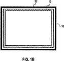
図1Aおよび図1Bは、本発明のクロージャ10の略部分断面および底面図を示す。図1Aはまた、コンタクトゾーン30においてクロージャ10と接触している1次メンバ20の部分を描く。接触は、1次メンバの突起部22によって達成される。1次メンバ20は、対象とする流体を保持し得る多数のリザーバ24、26、28を有する。図1Aにおいて、クロージャ10は、ある量の流体のためのリザーバ12を有することがわかる。図1Bの底面図において、このリザーバはクロージャ10のアウタエッジ全体のまわりを回る連続的チャネルであることがわかる。クロージャ10のアウタエッジはまた、これもエッジ全体のまわりを回るリップ32を有する。図示されていないが、1次メンバ20の突起部22も1次メンバのエッジ全体のまわりを回る。 1A and 1B show a schematic partial cross-section and bottom view of a
流体の少量の滴下が適切な表面に付着した場合、表面が地球の重力に対して異なる向きに移動したときでも、それらの滴下が適切な位置のままであることが観測されている。例えば、液滴が逆さまである場合も、液滴は表面に付着したままであり得る。この理由は、少量の液滴に関して、重力の引力は表面力に比較して小さいからである。同じ形状で異なるサイズの一連の液滴を考慮する場合、重量−および従って引力−は、液滴サイズの3乗に比例し、一方、表面力は液滴サイズの2乗に比例するに過ぎない。このため、より小さい液滴寸法(一般的に「マイクロフルイディック」と呼ばれる液滴寸法を含む)において、表面力が優位を占める。同様に、表面力の優位性のために、少量の流体は非常に小さい穴を通過することが困難である。なぜなら流体の重量からの圧力は、表面張力に打ち勝って、穴を通過するのに不十分であるからである。 It has been observed that when a small drop of fluid adheres to the appropriate surface, the drop remains in place even when the surface moves in a different direction with respect to the earth's gravity. For example, even if the droplet is upside down, the droplet may remain attached to the surface. This is because, for a small amount of droplets, the gravitational attraction is small compared to the surface force. When considering a series of droplets of the same shape but of different sizes, the weight-and hence the attractive force-is proportional to the cube of the droplet size, while the surface force is only proportional to the square of the droplet size. . For this reason, surface forces dominate at smaller droplet sizes (including droplet sizes commonly referred to as “microfluidic”). Similarly, small amounts of fluid are difficult to pass through very small holes due to the superiority of surface forces. This is because the pressure from the weight of the fluid is insufficient to overcome the surface tension and pass through the hole.
本発明の一部の実施形態において、クロージャリザーバは、地球の重力が流体を引き離す傾向がある場合でも、表面力が流体をリザーバの適切な位置に保持することが可能なほど十分に小さい寸法であることが好ましい。例えば、本発明のこの実施形態のクロージャは、ウェルプレートのための実質的に平らなリッドであり得、リザーバは、リッドの下部表面における小さな半球のくぼみであり得る。これらのくぼみが十分小さい場合、くぼみが保持する最大量の流体でさえ、地球の重力場に対してどの方向でも、単に表面力によって、適切な位置のままでいることが可能である。 In some embodiments of the present invention, the closure reservoir is dimensioned small enough that surface forces can hold the fluid in place in the reservoir even when the earth's gravity tends to pull the fluid away. Preferably there is. For example, the closure of this embodiment of the invention can be a substantially flat lid for the well plate and the reservoir can be a small hemispherical indentation in the lower surface of the lid. If these indentations are small enough, even the maximum amount of fluid that the indentation retains can remain in place in any direction relative to the Earth's gravitational field, simply by surface forces.
本発明において、流体をクロージャリザーバに定期的に補充することが可能であることが好ましい。このようにして、これらのリザーバは、例えば溶剤などの流体の適切な供給を常に有する。この定期的な補充は、容器からクロージャを取り外すこと、クロージャの位置を逆さまにするかまたはさもなければクロージャの向きを変更すること、および容器の内部に向かって開く開口部を通ってリザーバの中へ流体を分配するある種の流体輸送システムを用いることによって、行なわれ得る。流体輸送システムは、例えば、自動化ピペッティングシステム、またはチップベース輸送システム、または音響排出システムであり得る。 In the present invention, it is preferable to be able to periodically replenish the closure reservoir with fluid. In this way, these reservoirs always have a suitable supply of fluid, for example a solvent. This regular replenishment involves removing the closure from the container, turning the closure upside down or otherwise reorienting the closure, and opening the reservoir through an opening that opens toward the interior of the container. This can be done by using some sort of fluid transport system that distributes fluids to. The fluid transport system can be, for example, an automated pipetting system, or a tip-based transport system, or an acoustic ejection system.
あるいは、補充がクロージャを容器の1次メンバから取り外すことなく行なわれ得るような方法で、クロージャが設計され得る。従って、例えば、クロージャは、取り外し可能なカバーもしくはプラグ、または代わりに、取り外すことなく補充が可能なタイプの隔壁プラグ、例えばABgene(Epsom、英国)製の隔壁プラグを有するように設計し得る。リザーバは、容器の内部に向かって開く1つ以上の開口部、および取り外し可能なカバーまたはプラグが取り外されたとき露出する別の開口部を有する。クロージャのリザーバへの流体の補充は、カバーまたはプラグを取り外すこと、流体を分配すること、次いで、カバーまたはプラグを取り替えることによって実施され得る。追加された流体がクロージャリザーバに既に存在する流体の全体に対し与える衝撃を低くするように、分配処理を適切に制御することによって、また、容器の内部に向かって開く開口部が十分に小さい場合、流体の追加は、どの流体もリザーバから容器の内部に進むようにはしない。例えば、クロージャの内部への開口部を有しないリザーバへ分配すること、および次いで分配された流体が適切なサイズのチャネルを通ってこれらのリザーバからそのような開口部を有する他のリザーバにゆっくり進むことを可能にすることは可能である。用いられる流体輸送システムは、再び、例えば、自動化ピペッティングシステム、またはチップベース輸送システム、または音響排出システムであり得る。 Alternatively, the closure can be designed in such a way that refilling can be performed without removing the closure from the primary member of the container. Thus, for example, the closure may be designed to have a removable cover or plug, or alternatively a septum plug of the type that can be refilled without removal, such as a septum plug made from ABgene (Epsom, UK). The reservoir has one or more openings that open toward the interior of the container and another opening that is exposed when the removable cover or plug is removed. Refilling the closure reservoir may be performed by removing the cover or plug, dispensing the fluid, and then replacing the cover or plug. By properly controlling the dispensing process so that the added fluid has a low impact on all of the fluid already present in the closure reservoir, and when the opening opening towards the interior of the container is small enough The addition of fluid does not cause any fluid to travel from the reservoir to the interior of the container. For example, dispensing to reservoirs that do not have openings to the interior of the closure, and then the dispensed fluid slowly proceeds from these reservoirs through other appropriately sized channels to other reservoirs having such openings. It is possible to make it possible. The fluid transport system used can again be, for example, an automated pipetting system, or a chip-based transport system, or an acoustic ejection system.
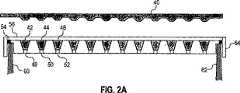
図2A−図2Bは、クロージャを取り外すことなくクロージャリザーバに溶剤の供給の補充を可能にする機能を有する、ウェルプレートのためのクロージャの略断面および平面図を描く。図2Aはまた、クロージャのためのカバー40およびクロージャと接触している容器の1次メンバからの突起部60、62を描く。クロージャ64は、流体を保持し得る多数のリザーバ42、44、46を有する。これらのリザーバ間に56および58などのチャネルが走っている。各リザーバは、48、50、52などの開口部を有し、該開口部は、流体の蒸発が下方に進むことを可能にするが、使用時に、流体の下方への総移動が起こらないほど十分に小さい。クロージャ64はまた、リザーバ54を有し、リザーバ54は、図2Bの平面図に見られ得るように、クロージャ64のエッジの回り全体に走っている。 FIGS. 2A-2B depict a schematic cross-section and top view of a closure for a well plate that has the ability to replenish the supply of solvent to the closure reservoir without removing the closure. FIG. 2A also depicts a cover 40 for the closure and protrusions 60, 62 from the primary member of the container in contact with the closure. The closure 64 has a number of
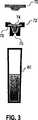
図3は、これも溶剤の供給を補充する機能を有する、テストチューブ80のためのクロージャを略断面にて描く。クロージャ72はプラグ70を有する。クロージャ72は流体のためのリザーバ74を提供する。リザーバ74は、流体の蒸発が下方に進むことを可能にするが、使用時に、流体の下方への総移動が起こらないほど十分に小さい開口部76を有する。クロージャ72がテストチューブ80に接触するコンタクトゾーンの近辺のクロージャの回りにも開口部78がある。 FIG. 3 depicts in a schematic cross section a closure for a
前に注意されたように、クロージャは容易に開閉が可能であることが好ましい。多くの場合、本発明のクロージャは、化学および生物医学において容器の操作のために一般的に用いられるタイプのロボットアームによって開閉されるように改造される。従って、例えば、クロージャが位置を下げることによって適切な位置に置かれ、次いでクロージャを位置から単に上げることによってクロージャが開かれ得れば、それが好ましい。地球の重力がクロージャを適切な位置に保持するのに十分であることがまた好ましい。地球の重力が、クロージャと1次メンバとの間にシールを形成するに十分であることが好ましい。 As noted before, it is preferred that the closure can be easily opened and closed. In many cases, the closures of the present invention are modified to be opened and closed by a robotic arm of the type commonly used for chemical and biomedical container manipulation. Thus, for example, it would be preferable if the closure could be put in place by lowering the position and then opened by simply raising the closure from position. It is also preferred that the earth's gravity be sufficient to hold the closure in place. Preferably, the earth's gravity is sufficient to form a seal between the closure and the primary member.
クロージャの設計に関連する考察の中で、次のことが注意され得る。第1に、容器の全容積が対象とする流体を入れるに必要な最小容積に近いものに減少することが好ましい。容器内のヘッドスペースが大きければ大きいほど、蒸気圧に近づく分圧を設定するように蒸発しなければならない流体の量が大きくなる。第2に、流体が表面力によってクロージャリザーバに保持される程度まで、クロージャがクロージャの挿入および除去の処理を伴う不可避的な力に従う場合、これらの表面力が流体をその位置に保持するに十分であることが望ましい。好ましくは、挿入および除去の処理は、クロージャを有効な力の支配下に置くわけではないが、実際上、この処理が人間または汎用ロボットアームによって実行される程度まで、1次メンバに対するある程度のクロージャの衝撃があり、多かれ少なかれクロージャの急激な減速という結果となる。クロージャリザーバに保持される流体のある自由表面は、衝撃力の方向とほぼ平行に位置することは特に好ましい。さらに、流体を保持するクロージャリザーバの能力を向上させるために、クロージャリザーバにおいて機械的設計のエレメントまたは泡沫を用いることが可能である。泡沫は、例えば、空隙を接続している連続気泡を含み得るので、泡沫は、相当な量の液体を保持し、液体が泡沫の範囲全体を移動することを可能にする能力を有する。溶剤がDMSOである場合、ポリエチレン泡沫のような、DMSOへの長期間の露出に耐え得る泡沫が好ましい。連続気泡ポリエチレンは、Chi Meng Industry(Tainan,Taiwan)製のOPCELL(http://www.chimeng.com.tw/e−opcell.htmに記述されている)である。第3に、クロージャリザーバのためのプラグおよび/またはカバーが好ましいとして示されているが、気体が、例えば、小さな通気口でクロージャリザーバに入りおよび出ることを可能にするある能力を有することも好ましい。この能力は、例えば、クロージャリザーバ内のどのエアスペースにおいても真空の形成を防ぐ。市販の隔壁プラグの使用は、この目的のために適切な程度の通気を提供し得る。 Among the considerations related to closure design, the following may be noted. First, it is preferred that the total volume of the container be reduced to a value close to the minimum volume required to contain the fluid of interest. The larger the head space in the container, the greater the amount of fluid that must be evaporated to set the partial pressure closer to the vapor pressure. Second, to the extent that the fluid is retained in the closure reservoir by surface forces, these surface forces are sufficient to hold the fluid in place if the closure is subject to inevitable forces involving the insertion and removal process of the closure. It is desirable that Preferably, the insertion and removal process does not place the closure under effective force control, but in practice some degree of closure on the primary member to the extent that this process is performed by a human or universal robot arm. The impact of this is more or less a result of a sudden deceleration of the closure. It is particularly preferred that the free surface with the fluid held in the closure reservoir is located substantially parallel to the direction of the impact force. In addition, mechanically designed elements or foams can be used in the closure reservoir to improve the ability of the closure reservoir to hold fluid. Foam can include, for example, open cells connecting voids, so that the foam has the ability to hold a substantial amount of liquid and allow the liquid to move through the entire range of foam. When the solvent is DMSO, a foam that can withstand prolonged exposure to DMSO, such as polyethylene foam, is preferred. Open-cell polyethylene is OPCELL (described in http://www.chimeng.com.tw/e-opcell.htm) from Chi Meng Industry (Tainan, Taiwan). Third, although a plug and / or cover for the closure reservoir is shown as preferred, it is also preferred to have some ability to allow gas to enter and exit the closure reservoir, for example, with a small vent. . This capability prevents, for example, the formation of a vacuum in any air space within the closure reservoir. The use of commercially available septum plugs can provide an adequate degree of ventilation for this purpose.
良好なシールの形成を容易にするために、1次メンバに接触しているクロージャの部分が、規格準拠の材料から作られることは、しばしば望ましい。規格準拠により、クロージャが適正な位置に置かれた場合、弾力的に変形し、1次メンバの外形に一致し、よりきつく封じるシールが提供される。 In order to facilitate the formation of a good seal, it is often desirable that the portion of the closure in contact with the primary member be made from a standard compliant material. Standards compliance provides a tighter seal that conforms to the outer shape of the primary member and elastically deforms when the closure is in place.
本発明のクロージャおよび容器を形成するための材料の選択は、対象とする流体と共用できるという必要性によっても制約される。これらの流体のうち、DMSOのみまたはDMSOと水が溶剤である流体は、化学および生物医学の研究において特に対象となる。DMSOと共用できる材料は、環状オレフィンコポリマー(COC)、ポリエチレン(PE)、ポリプロピレン(PP)、エチレン−プロピレンゴム(EPR)およびポリテトラフルオロエチレン(PTFE)を含む。COCは、Celanese Corporationの一部門であるTicona Engineering Polymers(Summit,New Jersey)によって製作され、Topasの商標で販売されている。1つの好ましいTopasレジンは8007である。これらの材料は、本発明において用いられるクロージャおよび1次メンバを形成するために有利に用いられ得る。一般的に、1次メンバおよびクロージャは、好ましくは、容易に製造可能であり、最も好ましくは、1つのコンポーネントまたは2つもしくは3つのコンポーネントであって後に一緒にされるコンポーネントからなる射出成形によって製造可能であることである。 The choice of materials for forming the closures and containers of the present invention is also limited by the need to be able to share with the fluid of interest. Of these fluids, DMSO alone or fluids in which DMSO and water are solvents are of particular interest in chemical and biomedical research. Materials that can be used with DMSO include cyclic olefin copolymers (COC), polyethylene (PE), polypropylene (PP), ethylene-propylene rubber (EPR) and polytetrafluoroethylene (PTFE). COC is manufactured by Ticona Engineering Polymers (Summit, New Jersey), a division of Celanese Corporation, and sold under the trademark Topas. One preferred Topas resin is 8007. These materials can be advantageously used to form the closures and primary members used in the present invention. In general, the primary member and closure are preferably easily manufacturable and most preferably manufactured by injection molding consisting of one component or two or three components that are later brought together. It is possible.
一部の状況下において、クロージャリザーバから容器の内部への開口部は、蒸気の交換のために比較的大きな表面積を有する必要があり得る。このことは、例えば、対象とする流体の量が非常に少ない場合に起こり得る。その場合、外部に対して非常に良いシールの状態でも、単に容器の内部を蒸気で満たすために、望ましくない量の蒸発が起こり得る。これを防ぐために、クロージャリザーバは、容器の内部の分圧をかなり急速に上昇させることが可能である必要があり、これは大きな表面積によって達成され得る。大きな表面積が必要である場合の実現性のいくつかは、多数の小さな開口部と共に、泡沫、ゲル、および気体拡散をし得るが流体の大量の移動をし得ない類似の材料である。クロージャリザーバから内部への開口部の表面積は、例えば、1次メンバのリザーバに保持されている対象とする流体の表面積の10%、20%、または100%であることが望ましい。 Under some circumstances, the opening from the closure reservoir to the interior of the container may need to have a relatively large surface area for vapor exchange. This can occur, for example, when the amount of fluid of interest is very small. In that case, even with a very good seal against the outside, an undesired amount of evaporation can occur simply because the inside of the container is filled with steam. To prevent this, the closure reservoir needs to be able to raise the partial pressure inside the container fairly rapidly, which can be achieved by a large surface area. Some of the possibilities when large surface areas are required are foams, gels, and similar materials that can diffuse gases but do not allow large amounts of fluid movement with a large number of small openings. Desirably, the surface area of the opening from the closure reservoir to the interior is, for example, 10%, 20%, or 100% of the surface area of the fluid of interest held in the reservoir of the primary member.
クロージャまたは容器を設計する場合、容器が用いられているとき対象とする流体の表面積は知り得ないが、容器の形状に基づき、その表面積に概略または正確な上限を設定することはしばしば可能であろう。クロージャリザーバから内部への開口部の表面積は、次いで、その上限の10%、20%、100%、またはあるその他の適切なパーセンテージであるように好都合に選ばれ得る。多くの容器の形状に関して、特にコンタクトゾーンがほぼまたは正確に平面である場合、便利な概略の上限は、単純に、内部に開く、クロージャまたは1次メンバの表面のコンタクトゾーンの平面への突起部の面積である。ウェルプレートに関して、便利な概略の上限は、すべてのウェルの全断面積である。当業者によって気づかれるようにこの上限は、メニスカス効果に対して訂正され得る。 When designing a closure or container, it is not possible to know the surface area of the fluid of interest when the container is used, but it is often possible to set a rough or accurate upper limit on the surface area based on the shape of the container. Let's go. The surface area of the opening from the closure reservoir to the interior can then be conveniently chosen to be 10%, 20%, 100%, or some other suitable percentage of its upper limit. For many container shapes, particularly where the contact zone is approximately or exactly planar, a convenient approximate upper limit is simply the protrusion of the closure or primary member surface into the plane of the contact zone that opens into the interior. Area. For well plates, a convenient approximate upper limit is the total cross-sectional area of all wells. This upper limit can be corrected for the meniscus effect, as will be noticed by those skilled in the art.
クロージャリザーバの設計において有用であり得る長所のさらなる形態は、クロージャが適切に位置しているときクロージャリザーバから来る容器内の溶剤またはその他の流体の分圧のパーセンテージである。従って、例えば、分圧の少なくとも10%、20%、または100%が、1次メンバに詰められる流体の特定な条件の下で、クロージャリザーバから来ることは指定され得る。 A further form of advantage that may be useful in the design of a closure reservoir is the percentage of the partial pressure of the solvent or other fluid in the container that comes from the closure reservoir when the closure is properly positioned. Thus, for example, it can be specified that at least 10%, 20%, or 100% of the partial pressure comes from the closure reservoir under the specific conditions of the fluid being loaded into the primary member.
クロージャリザーバの長所の別の形態は、クロージャリザーバの、1次メンバ内の対象とする流体に対する容積率である。この率が低い場合、蒸発が起こると、クロージャリザーバはかなり頻繁に補充を必要とする。この理由のため、クロージャリザーバの容積は、対象とする流体の容積の10%より大きいこと、好ましくは対象とする流体の容積の20%より大きいこと、または50%より大きいことが好ましい。クロージャまたは容器を設計する場合、容器が使用中容器に入れられる対象とする流体の容積は知り得ない。この理由のために、クロージャリザーバの容積を、1次メンバが保持し得るかまたは対象とする流体が有し得る最大容積に対して設計することが便利であり得、その結果、例えば、1次メンバリザーバが保持し得る最大容積の1%より大きい、または5%より大きい、または10%より大きい、または20%より大きい、または50%より大きいクロージャリザーバの容積を得る。 Another form of advantage of the closure reservoir is the volume ratio of the closure reservoir to the fluid of interest within the primary member. If this rate is low, the closure reservoir needs replenishment quite often when evaporation occurs. For this reason, the volume of the closure reservoir is preferably greater than 10% of the volume of the target fluid, preferably greater than 20% or greater than 50% of the volume of the target fluid. When designing a closure or container, it is not possible to know the volume of fluid that is intended to be placed in the container during use. For this reason, it may be convenient to design the volume of the closure reservoir with respect to the maximum volume that the primary member can hold or the target fluid can have, for example, the primary Obtain a volume of the closure reservoir that is greater than 1%, or greater than 5%, or greater than 10%, or greater than 20%, or greater than 50% of the maximum volume that the member reservoir can hold.
化学および生物医学の研究において一般的に用いられる溶剤は、吸湿性があり得る。特に、DMSOはかなり吸湿性があること、およびDMSO溶液は一般的に大気から湿気を引き寄せることは周知である。多くの状況において、吸湿性溶剤を含む対象とする流体が大気から湿気を引き寄せるというこの現象は、望ましくない。従って、密閉シールは、蒸発しないようにするのに役立つのみならず、対象とする流体が大気から望ましくない湿気を引き寄せないようにするのに役立つ。 Solvents commonly used in chemical and biomedical research can be hygroscopic. In particular, it is well known that DMSO is quite hygroscopic and that DMSO solutions generally draw moisture from the atmosphere. In many situations, this phenomenon of the target fluid containing the hygroscopic solvent attracts moisture from the atmosphere is undesirable. Thus, the hermetic seal not only helps to prevent evaporation but also helps to keep the subject fluid from drawing unwanted moisture from the atmosphere.
吸湿性溶剤に関連して、本発明のさらなる局面は、空気から湿気を引き寄せる湿潤剤の使用である。特に、本発明のクロージャにある1つ以上のリザーバは、湿潤剤を含むように設計され得る。そのようなリザーバは、好ましくは、クロージャと1次メンバとの間のコンタクトゾーンの近辺に、容器の外側の開口部と共に配置される。 In connection with hygroscopic solvents, a further aspect of the present invention is the use of a wetting agent that draws moisture from the air. In particular, one or more reservoirs in the closure of the present invention can be designed to contain a wetting agent. Such a reservoir is preferably arranged with an opening on the outside of the container in the vicinity of the contact zone between the closure and the primary member.
湿潤剤が採用されないとしても、新鮮な吸湿性溶剤で補充されたクロージャリザーバは、対象とする流体に類似した湿気を選択的に引き寄せることによって、それが湿潤剤として効果的に働くという利点を有し得る。 Even if no humectant is employed, a closure reservoir supplemented with fresh hygroscopic solvent has the advantage that it effectively acts as a humectant by selectively attracting moisture similar to the fluid of interest. Can do.
本発明の代わりの好ましい実施形態において、容器はクロージャを有する。容器は、対象とする流体のための1つ以上のリザーバを含む1次メンバを有する。1次メンバは、例えば、ウェルプレートまたはテストチューブであり得る。クロージャはまた、1つ以上の流体リザーバを含む。これらのリザーバの少なくとも一部は、容器がクロージャを用いて閉じられたとき、クロージャが1次メンバに接触するコンタクトゾーンの近くに、容器の外部に向かって開く開口部を有する。 In an alternative preferred embodiment of the present invention, the container has a closure. The container has a primary member that includes one or more reservoirs for the fluid of interest. The primary member can be, for example, a well plate or a test tube. The closure also includes one or more fluid reservoirs. At least some of these reservoirs have openings that open toward the exterior of the container near the contact zone where the closure contacts the primary member when the container is closed using the closure.
前の実施形態の容器を用いることにおいて、対象とする流体は、容器のリザーバ内に保持される。対象とする流体が含む溶剤は、1つ以上のクロージャリザーバに保持される。溶剤は、対象とする流体およびクロージャリザーバの両方から蒸発する。クロージャリザーバからの蒸発は、コンタクトゾーンの近辺において容器の外部に対する溶剤の分圧を上げる。溶剤が容器の内部から外部へ拡散する速度は、コンタクトゾーンの直近の内側と外側間での溶剤の分圧の差に関係するので、クロージャリザーバからの蒸発は、容器の内部からの溶剤の損失を減少させる傾向があることが予期され得る。 In using the container of the previous embodiment, the fluid of interest is retained in the reservoir of the container. The solvent contained in the fluid of interest is held in one or more closure reservoirs. The solvent evaporates from both the fluid of interest and the closure reservoir. Evaporation from the closure reservoir increases the partial pressure of the solvent to the outside of the container in the vicinity of the contact zone. The rate at which the solvent diffuses from the inside of the container to the outside is related to the difference in solvent partial pressure between the immediate inside and outside of the contact zone, so evaporation from the closure reservoir is a loss of solvent from inside the container. It can be expected that there will be a tendency to reduce.
容器の外部に向かった開口部付きのクロージャリザーバを用いることの効果を評価する方法は、クロージャゾーンの近辺における対象とする溶剤の分圧を決定することであり、該溶剤の分圧は、シールを介する溶剤の流出よりはむしろ、クロージャからの蒸発による。その点において、その圧力が、対象とする溶剤の蒸気圧の10%、好ましくは20%、より好ましくは50%、より好ましくは80%であれば望ましく、その結果、シールを介する対象とする溶剤の拡散は抑制される。このことに関係して考慮され得る長所の代わりの形態は、コンタクトゾーンの直近の外側の分圧のどのくらいのパーセンテージが、対象とする流体を含むリザーバよりはむしろクロージャリザーバから来るかである。クロージャリザーバからの分圧の少なくとも10%または20%のパーセンテージが好ましい。これに関連して考慮され得る長所の別の形態は、容器内の対象とする流体によって露出される流体表面に対するクロージャリザーバによって露出される流体表面の率である。例えば、率が1に近い場合のように、これらの表面が共用できる場合、容器内の対象とする流体からの蒸気はシールを通過しなければならず、クロージャリザーバからの蒸気は通過しないので、コンタクトゾーン近辺における対象とする溶剤の大部分の分圧はクロージャリザーバから来ることが予期される。 A method of evaluating the effect of using a closure reservoir with an opening towards the outside of the container is to determine the partial pressure of the solvent of interest in the vicinity of the closure zone, the partial pressure of the solvent being Rather than solvent spillage through the closure, it is by evaporation from the closure. In that respect, it is desirable if the pressure is 10%, preferably 20%, more preferably 50%, more preferably 80% of the vapor pressure of the solvent of interest, and consequently the solvent of interest through the seal. Diffusion is suppressed. An alternative form of merit that can be considered in this regard is what percentage of the partial pressure immediately outside the contact zone comes from the closure reservoir rather than the reservoir containing the fluid of interest. A percentage of at least 10% or 20% of the partial pressure from the closure reservoir is preferred. Another form of merit that can be considered in this regard is the ratio of the fluid surface exposed by the closure reservoir to the fluid surface exposed by the fluid of interest in the container. For example, if these surfaces can be shared, such as when the rate is close to 1, the vapor from the fluid of interest in the container must pass through the seal and the vapor from the closure reservoir will not pass, It is expected that the partial pressure of most of the solvent of interest near the contact zone will come from the closure reservoir.
クロージャゾーンの近辺において容器の外部に露出されたクロージャリザーバを有するさらなる利点は、クロージャリザーバ内の吸湿性溶剤、特に補充から結果として生じる新鮮な吸湿性溶剤が、湿潤剤として効果的に働き、水蒸気を引きつけ、クロージャゾーンの近辺における水蒸気の濃縮を減少させ、よって、水蒸気が容器に入るのを防ぐ、能力である。 A further advantage of having a closure reservoir exposed outside the container in the vicinity of the closure zone is that the hygroscopic solvent in the closure reservoir, in particular the fresh hygroscopic solvent resulting from replenishment, effectively acts as a wetting agent, The ability to attract and reduce the concentration of water vapor in the vicinity of the closure zone, thus preventing water vapor from entering the vessel.
容器がコンタクトゾーンから外側への気体の拡散を遅くするのに役立つある種の構造を備えている場合、一般的に、前の実施形態において特に、好ましい。一般的にこれらの構造は、気体がコンタクトゾーンの直近の外部から一般大気に移動するときに通る拡散経路を長くし、狭くする構造である。種々様々なそのような構造は、時々「ラビリンスシール」と呼ばれるが、当業者が思いつくことである。 It is generally particularly preferred in the previous embodiment if the container is equipped with a certain structure that helps slow the diffusion of gas out of the contact zone. Generally, these structures are structures that lengthen and narrow the diffusion path through which gas travels from the immediate outside of the contact zone to the general atmosphere. A wide variety of such structures, sometimes referred to as “labyrinth seals”, is conceivable to those skilled in the art.
一般的に、ラビリンスシールは、気体の分子が対象とする任意の流体から容器の外側へ進まなければならない通路の長さを増加させ、ラビリンスが全部または一部において容器の外部にある場合、ふさがれない周囲に開くようにする。この長さを「気体交換通路長」と呼び得る。クロージャおよび1次メンバにおける突起部は、突起部が気体拡散の障害物として働く場合、この通路を増加させるように働き得る。ラビリンスシールの有効性の対策は、ラブリンスシールが提供する通路長の増加である。本発明の容器のそのような増加は、好ましくは、少なくとも1mm、より好ましくは少なくとも2mm、およびより好ましくは1cmである。適正に置かれたシールを有する気体交換通路長は、ラビリンスシールがない場合の気体交換通路長に比較して、リビリンスシールのない長さより、好ましくは25%以上、およびより好ましくは100%以上である。ラブリンスシールの有効性の代わりの対策は、外側に到達するために外側に最も近い対象とする流体の表面から通路を追跡するために、分子が受けなければならない方向の変化の回数を調べることである。 In general, the labyrinth seal increases the length of the passage that gas molecules must travel from any fluid of interest to the outside of the container, and when the labyrinth is wholly or partially outside the container, To open around. This length can be referred to as the “gas exchange path length”. The protrusions in the closure and primary member can serve to increase this passage when the protrusions act as gas diffusion obstacles. A countermeasure for the effectiveness of the labyrinth seal is to increase the passage length provided by the Labrinse seal. Such an increase in the container of the present invention is preferably at least 1 mm, more preferably at least 2 mm, and more preferably 1 cm. The length of the gas exchange passage with a properly placed seal is preferably 25% or more, and more preferably 100% or more, compared to the length without the labyrinth seal, compared to the length without the labyrinth seal. It is. An alternative measure to the effectiveness of the labyrinth seal is to examine the number of direction changes that a molecule must undergo to track the passage from the surface of the target fluid closest to the outside to reach the outside. It is.
クロージャリザーバが容器の内部に向かって開かれた本発明のその前の実施形態に関するように、前の実施形態は、流体をクロージャリザーバに補充することが望ましい。そのような補充は前述のように、クロージャを取り外すことによって、または、クロージャを容器から取り外すことなく流体が補充され得る開口部を提供することによって、行なわれ得る。該開口部はプラグまたはカバーを利用し得る。 As with previous embodiments of the invention in which the closure reservoir is opened toward the interior of the container, the previous embodiment desirably replenishes the closure reservoir with fluid. Such refilling can be done by removing the closure, as described above, or by providing an opening that can be refilled with fluid without removing the closure from the container. The opening may utilize a plug or cover.
理解されるように、一部のクロージャリザーバは容器の内部に向かって開き、他のリザーバは容器の外部に向かって開くという本発明の実施形態があり得る。 As will be appreciated, there may be embodiments of the present invention where some closure reservoirs open toward the interior of the container and other reservoirs open toward the exterior of the container.
特に本発明のさらなる好ましい実施形態において、クロージャに接触する1次メンバの部分が、クロージャと1次メンバが接触している場合、流体によって部分的に囲まれ得るように、クロージャリザーバは設計される。従って、このリザーバは、容器が閉じられるとき、容器の内部および外部の両方に向かって開く。この設計は、家庭の配管における水トラップとのある類似性をもつタイプのシールを作製する。容器の内部からの蒸気は、容器の外部へ流出するために、コンタクトゾーンを囲む流体を通過しなければならない。コンタクトゾーンを囲む流体の適切なレベルが維持される限り、そのようなシールは、水蒸気の流入量を制限すると共に、蒸発の防止に非常に効果的であり得る。この実施形態に関して、クロージャと1次メンバとの接触がなされるクロージャリザーバに規定のレベルの流体を容易に補充することが可能であることは特に興味があり得る。このリザーバは、容易に理解されるように、1次メンバの形状に従わなければならなく、その結果、例えば、1次メンバがテストチューブである場合、クロージャリザーバは環状の両端の開いたテストチューブ受け取ることが可能でなければならない。 In particular, in a further preferred embodiment of the invention, the closure reservoir is designed so that the part of the primary member that contacts the closure can be partially surrounded by the fluid when the closure and the primary member are in contact. . Thus, this reservoir opens towards both the interior and exterior of the container when the container is closed. This design creates a type of seal that has some similarity to water traps in household piping. Vapor from inside the container must pass through the fluid surrounding the contact zone in order to flow out of the container. As long as the proper level of fluid surrounding the contact zone is maintained, such a seal can be very effective in limiting water vapor inflow and preventing evaporation. With respect to this embodiment, it may be of particular interest to be able to easily replenish a defined level of fluid into the closure reservoir in which contact is made between the closure and the primary member. This reservoir must follow the shape of the primary member, as will be readily understood, so that, for example, if the primary member is a test tube, the closure reservoir is an annular open test tube at both ends. It must be possible to receive.
あるいは、クロージャに接触する1次メンバの部分を浸すために流体を供給するクロージャリザーバの代わりに、1次メンバのリザーバは、1次メンバに接触するクロージャの部分を浸すために流体を供給するように設計され得る。この設計によって、流体は、所望により定期的に補充され得る。その場合、クロージャは、ギャップまたはチャネルが装備され得、ギャップまたはチャネルは、コンタクトゾーンを囲むかまたはその近くに位置する1次メンバのリザーバに流体のレベルを維持するために、補充の流体をコンタクトゾーンに向かって導く。 Alternatively, instead of a closure reservoir that supplies fluid to immerse the portion of the primary member that contacts the closure, the reservoir of the primary member supplies fluid to immerse the portion of the closure that contacts the primary member. Can be designed to. With this design, the fluid can be replenished periodically as desired. In that case, the closure may be equipped with a gap or channel that contacts the replenishment fluid to maintain the fluid level in the reservoir of the primary member located around or near the contact zone. Guide towards the zone.
図2Aは、コンタクトゾーンの近辺にあり、1次メンバの部分を流体に浸すために働き得る開口部54と、クロージャ64に接触する突起部60の一部とを描く。図3もまた、開口部78を描き、開口部78は、コンタクトゾーンの近辺にあり、クロージャ72に接触する1次メンバ80の部分を流体に浸すために働き得る。 FIG. 2A depicts an
前の実施形態に関して、1次メンバに接触するクロージャの部分を有することが規格準拠であることも、特に利益があり得る。流体が存在するときに増加する規格準拠を有するクロージャの部分を有すること、および流体を吸収する能力があるクロージャの部分を有することも、興味があり得る。これに関して、「スライディングゲル」と呼ばれるポリマーの分類が検討された。このことは、例えば、米国特許第6,828,378号および2003年1月のオランダのUniversity of GroningenのM.van den Boogaardの博士論文、名称“Cyclodextrin−containing Supra−molecular Structures:From pseudo−polyrotaxanes towards molecular tubes,insulated molecular wires and topological networks”によって示される。後者の7章において、スライディングゲルは、そこで検討されるように、水またはDMSOにおけるスライディングゲルの乾燥重量のそれぞれ35倍および25倍を吸収し得ることが述べられている。 It may also be particularly beneficial to have a portion of the closure that contacts the primary member, as in the previous embodiment, to be compliant. It may also be of interest to have a portion of the closure that has increased standards compliance when fluid is present, and to have a portion of the closure that is capable of absorbing fluid. In this regard, a class of polymers called “sliding gels” was considered. This is described, for example, in US Pat. No. 6,828,378 and M. of University of Groningen, Netherlands, January 2003. Van den Boogarard's doctoral dissertation, named “Cyclodextrin-containing Super-molecular Structures: From pseudo-polyoxides and numbers of molecular tubes, in numbers. In the
図4は、1次メンバの部分を囲む流体92のリザーバを有するクロージャ90と、クロージャに接触する突起部96の一部とを略部分断面にて描く。クロージャは、また、追加のリザーバを有するとして描かれている。リザーバ92の上部に、容積98があり、容積98は、例えば、適切なスライディングゲルなどの流体を吸収する規格準拠の材料から構成される。容積98は、リザーバ92内の流体が補充される頻度を減少させる、さらなるリザーバとして働き得る。 FIG. 4 depicts a closure 90 having a reservoir of
図5は、本発明の代わりの好ましい実施形態を略部分断面にて描き、該好ましい実施形態は、ラビリンスシールとコンタクトゾーン118の近くに、容器の外側への開口部110を有する単一のクロージャリザーバ108とを有する。クロージャ100は、上部102および下部104から成り立ち、下部は、コンタクトゾーン118において1次メンバ106と接触する。1次メンバ106は、対象とする流体のための多数のリザーバ120、122、124を有する。クロージャの下部104は、容器のヘッドスペースを減らすために、これらのリザーバの上部の近くに接近する。クロージャの上部102は、1次メンバ106からクロージャを取り外すことなく、流体リザーバ108を補充するためのプラグ差し込み可能な穴112が装備されている。クロージャは、また、再補充処理を容易にするためのオプションの通気穴114および穴112にプラグ差し込みする処理を容易にする構造サポート116が装備されている。リザーバ108は、開後部110に向かって先細になっていて、開口部が近づくと狭くなる。先細は、毛管作用によって流体を開口部に向けて引き寄せる。リザーバ108に流体を保持するためのさらなる表面を提供するバッフル130がある。さらなる特徴が、流体を適正な位置に保持するためにリザーバ108に含まれる。例えば、他に位置する更なるバッフル、スパイラルウォールまたは泡沫である。開口部110は、流体が容積126の中に蒸発し、そこで高い分圧を生成し、上に示されるように、コンタクトゾーン118における不完全なシールを通って流体が出て行く速度を減少させるのに役立つ。リザーバ108から容器の内部に向かう開口部がない。但しそのような開口部は、希望に応じ追加され得る。図5に見られるように、一旦気体の分子がコンタクトゾーン118でシールを通過すると、気体の分子は容器から完全に出て行くように従わなければならない通路は、多数の屈曲を有し、容器の外側にラビリンスシールを提供する。ラブリンスシールにも関わらず、見られるように、部品102および104を備えているクロージャ100は、容器を開くことが望まれるとき、直接上に持ち上げられる。クロージャが1次メンバ106の上に再び戻されるとき、不可避的衝撃力がある。本実施形態において、前に注意されたように、この衝撃力は、開口部110における流体メニスカスと同じ方向に沿っていることが有利である。 FIG. 5 depicts an alternative preferred embodiment of the present invention in a generally partial cross-section, which is a single closure having an
本発明のさらなる好ましい実施形態において、容器に流体を貯蔵する方法が提供される。本発明のある方法において、溶剤を含む流体サンプルはリザーバに貯蔵される。リザーバは、1つ以上のクロージャリザーバを有するクロージャを用いて覆われる。クロージャリザーバは、多量の溶剤を含む。クロージャ内の溶剤は補充される。 In a further preferred embodiment of the present invention, a method for storing fluid in a container is provided. In some methods of the invention, a fluid sample containing a solvent is stored in a reservoir. The reservoir is covered using a closure having one or more closure reservoirs. The closure reservoir contains a large amount of solvent. The solvent in the closure is replenished.
上に注意されたように、溶剤の補充のステップは、好ましくは容器からクロージャを取り外すことなく、本発明の方法が行われることである。既に記述されたように、この目的のために、カバーおよびプラグが装備される。 As noted above, the solvent replenishment step is preferably performed without removing the closure from the container. As already described, for this purpose a cover and a plug are equipped.
本発明の方法において、特に、流体はウェルプレートに貯蔵され得る。ウェルプレートまたは流体のための複数の分離されたリザーバを有するその他の1次メンバが用いられる場合、方法は、好ましくは共通の溶剤を有する多数の対象とする流体を貯蔵することに適用する。本発明の方法がウェルプレートと共に実施される場合、ウェルプレートが積み重ね(stacking)によって貯蔵されることが一般的である。従って、本発明のクロージャは、好ましくは、本発明の複数の容器が心地よくかつ安全に互いの上に積み重なるように設計される。 In the method of the invention, in particular, the fluid can be stored in a well plate. Where a well plate or other primary member having a plurality of separate reservoirs for fluids is used, the method preferably applies to storing a number of fluids of interest having a common solvent. When the method of the present invention is performed with a well plate, it is common for the well plate to be stored by stacking. Accordingly, the closure of the present invention is preferably designed so that the containers of the present invention stack comfortably and safely on top of each other.
本発明の方法は、好ましくは、自動的に実行される。全実験室オートメーションシステムは、例えば、ウェルプレートを保持するカルーセル、ウェルプレートをひとつの器具から別の器具に移動させるロボットアーム、種々の分析器具および反応室、ピンベースの流体移動システム、および/または音響排出システムを含み得る。システムの全目的は、多量の流体を受け入れ、それらを分析下に置き(例えば、それらの組成および物理的特性の確認を含む)、特定の部分を生成するように設計された反応、および精製ステップを含み得、その間中、コンピュータまたは他の手段によって、システムにおける各流体の起点および行先、ならびに各流体に関する処理および結果を潜在的に行方を見失わないようにする。 The method of the present invention is preferably performed automatically. All laboratory automation systems include, for example, carousels that hold well plates, robot arms that move well plates from one instrument to another, various analytical instruments and reaction chambers, pin-based fluid transfer systems, and / or An acoustic ejection system may be included. The overall purpose of the system is to accept large volumes of fluids, place them under analysis (including confirmation of their composition and physical properties, for example), reactions designed to produce specific parts, and purification steps In the meantime, by computer or other means, the origin and destination of each fluid in the system, as well as the processing and results for each fluid, are potentially not lost.
各流体の起点、行先、処理および結果の追跡は、例えば、流体移動システムコントローラなどのコントローラを単層ファイルとしてまたはデータベース内に記憶する汎用コンピュータにその情報を通信させることによって、実行され得る。流体は、識別子をシステムにおける各ウェルプレートに割り当てること、および、各プレートの各ウェルの内容に関する全履歴を生成することを可能にする方法で、各プレート内の各ウェルに特定回数で何が行なわれたかを追跡することによって、便利に識別され得る。これに関連して、心に留めておかなければならないことは、システムにおける流体の必ずしもすべての変化が意図的または計画的な動作の結果として起こるわけでなく、一部は、時間の経過の結果起こる不可避の変化であり得、該変化は、例えば、貯蔵時における大気からの水分の吸収または流体の蒸発などとしてであり、それらに本発明の容器および方法が関係する。 Tracking the origin, destination, processing, and results of each fluid may be performed, for example, by having a controller, such as a fluid movement system controller, communicate that information to a general purpose computer that stores it as a single layer file or in a database. What the fluid does at a specific number of times for each well in each plate is a method that allows assigning an identifier to each well plate in the system and generating a full history of the contents of each well in each plate By tracking what has been done, it can be conveniently identified. In this context, it is important to keep in mind that not all changes in the fluid in the system occur as a result of intentional or planned operation, in part, as a result of the passage of time. There may be unavoidable changes that occur, such as absorption of moisture from the atmosphere during storage or evaporation of fluids, to which the containers and methods of the invention relate.
実験室オートメーションシステムにおいて、様々なメーカからの機器を統合することが一般的に必要である。これに関係して、特定の規格を支持することは、流体移動システムの望ましい特徴であり得る。製造環境の一部を形成する、ある流体移動および貯蔵システムは、薬工業によって理解されるように、「良好な製造の実行(Good Manufacturing Practice(GMP)」の基準への全システム準拠をサポート可能であることと共に製造に関するさらなる規格を満たすことが必要であり得る。 In laboratory automation systems, it is generally necessary to integrate equipment from various manufacturers. In this regard, supporting a particular standard may be a desirable feature of a fluid transfer system. A fluid transfer and storage system that forms part of the manufacturing environment can support full system compliance with “Good Manufacturing Practice (GMP)” standards, as understood by the pharmaceutical industry. It may be necessary to meet further standards for manufacturing.
本発明の好ましい実施形態において、容器のクロージャは、少なくとも2つのクロージャメンバを備えている。クロージャメンバの互いの相対位置は、クロージャと容器の対に応じて変更される。 In a preferred embodiment of the invention, the closure of the container comprises at least two closure members. The relative positions of the closure members are changed according to the closure and container pair.
クロージャメンバの相対位置の変更は、1つ以上のメンバが容器により近くに接近する結果となり得る。変更は、1つ以上のメンバが容器をプレスする結果となり得る。プレスは、容器内の流体からの蒸気のための出口通路がプレスされた表面を通過することを必要とするように行なわれ得る。 Changing the relative position of the closure member can result in one or more members approaching the container closer. The change can result in one or more members pressing the container. The pressing can be done so that an exit passage for vapor from the fluid in the container needs to pass through the pressed surface.
クロージャメンバを容器に対してプレスするようにする動機づけは、他のことがすべて等しいとすると、そのようなプレスによって形成されるシールは、そのようなプレスなしに形成されるシールより密閉である。 The motivation to press the closure member against the container is that the seal formed by such a press is more tight than the seal formed without such a press, all else being equal. .
多くの場合において、クロージャのメンバの相対的な移動は、相対的な移動が可能であるように、メンバを接続することによって達成される。このことは、接続するエレメントの湾曲による弾性のあるコンポーネントによって、または、コンポーネントを動きばめ(loose fit)に連結させることによって、達成され得る。 In many cases, the relative movement of the closure members is accomplished by connecting the members such that relative movement is possible. This can be achieved by elastic components due to the curvature of the connecting elements or by coupling the components to a loose fit.
クロージャメンバが容器に対してプレスする場合、力は、好ましくは、クロージャを容器の上に置く処理によるなど、容器とクロージャの相互作用によって生成される。しかしながら、力は、磁石などの外部の手段によって生成され得る。 When the closure member presses against the container, the force is preferably generated by the interaction of the container and the closure, such as by a process of placing the closure on the container. However, the force can be generated by external means such as a magnet.
クロージャメンバの相対的移動は、2つのメンバが、互いにある角度の方向で容器に対してプレスするように設計され得る。この角度は、90度以上であり得る。ある実施形態において角度は約180度であり得、その結果、2つのメンバは、互いにほぼ反対の方向に容器に対してプレスする。 The relative movement of the closure member can be designed such that the two members press against the container in an angled direction relative to each other. This angle can be 90 degrees or more. In some embodiments, the angle can be about 180 degrees, so that the two members press against the container in generally opposite directions.
一般的に、容器が閉じているとき容器とクロージャが出会う場所は水平面に近い。通常の使用におけるクロージャは容器の上部にある。このように、重力は、クロージャが容器に付着されたままにすることに役立つ。 Generally, the location where the container and closure meet when the container is closed is near a horizontal plane. The closure in normal use is at the top of the container. Thus, gravity helps keep the closure attached to the container.
容器は、クロージャに合うほぼ垂直な突起部を有するように設計され得る。例えば、ウェルプレートのようにほぼ平らで、形が長方形であるクロージャは、例えば、クロージャの外側エッジを囲む2つの同心の垂直な突起部を有し得、クロージャは、垂直の突起部の1つまたは両方に合うように設計され得る。 The container can be designed to have a generally vertical protrusion that fits into the closure. For example, a closure that is generally flat and rectangular in shape, such as a well plate, may have, for example, two concentric vertical protrusions that surround the outer edge of the closure, where the closure is one of the vertical protrusions. Or it can be designed to fit both.
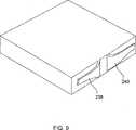
図6は、容器がウェルプレートで、クロージャがウェルプレートのためのリッドである本発明の例示的実施形態を描く。図の上の部分は、容器およびクロージャの一部を通る垂直断面を描く。下の部分は、容器およびクロージャを通る水平断面を描く。容器は、容器の周囲に2つの垂直突起部210および212を有する。クロージャは、上部メンバ214および下部メンバ216を有する。上部メンバと下部メンバとの間に、液体のためのリザーバがある。上部メンバは、上部メンバの回りに2つの垂直突起部218および220を有する。下部メンバは、両方の垂直突起部の内側になるように設計される。弾性のあるコンポーネントによって、下部メンバはプレートの内部突起部に対してプレスするようにされる。図6において、この弾性のあるコンポーネントは、下部クロージャメンバの2つの側面に付いた4つの部品222から構成されるとして示される。 FIG. 6 depicts an exemplary embodiment of the invention where the container is a well plate and the closure is a lid for the well plate. The upper part of the figure depicts a vertical section through the container and part of the closure. The lower part depicts a horizontal section through the container and closure. The container has two
図7は、図6の実施形態に関連して、弾性のあるコンポーネントに関する例示的な構造を概略描く。図6の上部のように、この図は、容器およびクロージャを通る垂直断面である。単純化のため、この図は、下部クロージャメンバ216およびその下部メンバ上で動作する弾性のあるコンポーネントの部分のみを描く。図の上の部分において、クロージャと容器226との接触の前の下部クロージャメンバ216が見える。弾性のあるコンポーネントはここに、図のクロージャの右に描かれ、該弾性のあるコンポーネントは、図6におけるように、一端が下部クロージャメンバに取りつけられている1つ以上の柔軟性あるメンバ228を備える。下部クロージャメンバ216が位置の中に下げられると、弾性のあるコンポーネント228は、容器の存在に応答し曲がり、下部クロージャメンバ216を左に送る力を生成する。圧力は、下部クロージャメンバを容器の内部突起部の左壁に対して押しつける。 FIG. 7 schematically depicts an exemplary structure for a resilient component in connection with the embodiment of FIG. Like the top of FIG. 6, this view is a vertical section through the container and closure. For simplicity, this figure only depicts the
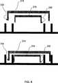
図8において、クロージャの上部メンバ214およびクロージャの下部メンバ216の両方を描く本発明のクロージャの略断面が見える。この図において、上部および下部クロージャメンバの両方は、取りつけられている弾性のあるコンポーネントポーション232および234を有する。弾性のあるコンポーネントは、図6および図7に示されるものとは多少異なる設計であり、クロージャメンバの壁の下に向かって取りつけられ、上に向かって延びている。上部クロージャメンバ214に関して、弾性のあるコンポーネントの対応するポーション234は、左手側に取りつけられて示され、一方、下部メンバ216は、右手側に取りつけられて描かれている弾性のあるコンポーネントの下部メンバのポーション232を有する。再び、図7におけるように、クロージャの上部および下部メンバが容器の上に向けて下げられた場合、弾性のあるコンポーネントは、メンバに対してそれぞれ右および左に動作する。従って、上部メンバは、容器の外側突起部に対してプレスし、一方、下部メンバは、内側突起部に対してプレスする。 In FIG. 8, a schematic cross section of the closure of the present invention depicting both the
図9は、図6および図7に描かれる種類の弾性のあるコンポーネントについてさらに詳細を提供する。弾性のあるコンポーネントは、クロージャメンバの側面から外側に突き出る2つのスプリング様部品238および240を有する。弾性のあるコンポーネントを形成するスプリング様の部品の各々は、先細であり、また先細の断面を有する。部品の形は、従って、いくらか翼の形のようである。図9は、鋭い下部エッジを有するスプリング様部品238および240を示すが、下部エッジはまた、丸くされるかまたは鈍くされ得、全体形状および断面の両方の先細は、多少緩やかにされ得る。この実施形態において、クロージャを容器に設置する下方への力は、まず、スプリング様部品238および240が本体により近くにプレスするように、指とスプリング様部品238および240のショルダとの間に力を加えることが意図されている。スプリング様部品238および240が容器に接触する正確な点は、挿入工程における公称寸法からの偏差およびクロージャおよび容器の誤調整と共に、設計詳細による。しかしながら、意図は、接触がなされるとスプリング様部品238および240は、クロージャメンバの主要部分に向かって押し込まれ、該主要部分に力を加えることである。 FIG. 9 provides further details for a resilient component of the type depicted in FIGS. 6 and 7. The resilient component has two spring-
図7および図8の実施形態において、内側および外側メンバの各側面に複数のスプリング様構造を用いることも可能である。例えば、下部メンバの1つの側面に取りつけられた3個または5個または10個のスプリング様構造を有し得る。さらに、下部メンバの2つの隣接する側(非反対側)に取りつけられたスプリング様構造を有し得る。これは図10に示され、図10は、2つの隣接する側面の各々に244などの多数のスプリング様構造を有する本発明のクロージャのメンバを概略的に描く。このことは、結果的に、下部メンバが容器突起部のコーナーに対してプレスし、従って、容器突起部の2つの壁に対してより良い、より密閉された接触を行なう。上部メンバに関して、スプリング様構造の同じ多様性が可能である。 In the embodiment of FIGS. 7 and 8, multiple spring-like structures can be used on each side of the inner and outer members. For example, it may have 3 or 5 or 10 spring-like structures attached to one side of the lower member. Further, it may have a spring-like structure attached to two adjacent sides (non-opposite sides) of the lower member. This is shown in FIG. 10, which schematically depicts a closure member of the present invention having multiple spring-like structures, such as 244, on each of two adjacent sides. This results in the lower member pressing against the corners of the container projection and thus making a better and more sealed contact to the two walls of the container projection. For the upper member, the same variety of spring-like structures is possible.
上部メンバのスプリング様構造が、下部メンバがプレスする内側容器突起部のコーナーの反対の外側容器突起部のコーナーに対してプレスする場合、内側容器突起部の内部は、すべての4つの側面に対して、より優れ、より密閉された接触によってほとんど完全に囲まれる。このことは、図11の底面図で見られ得、該底面図において、陰影のつけられた長方形は、図8の実施形態における容器の突起部210および212に対する上部クロージャメンバ214および下部クロージャメンバ216を描く。見られ得るように、拡散によって容器から外側に流出する流体の分子の通路は、より優れた圧力支援シールによって、右および下側(より太い線で示されるように)がふさがれる。従って流体の分子は、そのようなシールによってふさがれない内側突起部212の側面を通って外側へ移動する傾向がある(より細い線で示される)。しかしながら、流体の分子がそれらの側面を通って、外側に移動する場合、流体の分子は、左および上側(これもより太い線で示される)に描かれる外側突起部210上のより優れた圧力支援シールによってふさがれる傾向がある。 If the spring-like structure of the upper member presses against the corner of the outer container protrusion opposite the corner of the inner container protrusion pressed by the lower member, the interior of the inner container protrusion is against all four sides. And is almost completely surrounded by better, more sealed contacts. This can be seen in the bottom view of FIG. 11, in which the shaded rectangles are the
容器にある流体が、吸湿性であり、従って内側に拡散する水の分子の流れを止める傾向がある状況において、図11に示される配置も、水の内側への拡散を制限する傾向がある。 In situations where the fluid in the container is hygroscopic and therefore tends to stop the flow of water molecules diffusing inward, the arrangement shown in FIG. 11 also tends to limit the diffusion of water into the interior.
図8において簡略化のために、クロージャの上部および下部のメンバは、接続されているとして描かれていない。クロージャの2つのメンバを分離することは可能である。但し、それは、該2つのメンバは2つの動作において取り外されなければならないという不利益を有する。あるいは、上に検討されたように必要に応じ、クロージャの2つのメンバがクロージャに対してプレスするようにそれらのメンバを引き離すことが可能なほど十分な弾性を有する場合は、クロージャの2つのメンバを接続することは可能である。 For simplicity, the upper and lower members of the closure are not depicted as being connected in FIG. It is possible to separate the two members of the closure. However, it has the disadvantage that the two members must be removed in two operations. Alternatively, if the two members of the closure are sufficiently elastic to allow the two members of the closure to be pulled apart so that they press against the closure, as discussed above, the two members of the closure Can be connected.
クロージャが、例えばロボットアームまたは同様な自動化された機械によって、容易に容器に接触し、容器との接触から引き離すことが、特定の実施形態において望ましい。一般的にこれが実行される場合、ロボットアームがクロージャに対してしっかりとプレスしている間、容器もしっかりと保持される。クロージャが容器に接触するようにすることが必要である場合、ロボットアームはクロージャを容器の上の適切な計算された位置に運び、次いで適度の力でプレスダウンする。クロージャが置かれる位置は、容器の位置に基づき決定される必要があり、容器の位置は、例えばある種のセンサによって感知され得る。 In certain embodiments, it is desirable for the closure to be easily in contact with and away from contact with the container, for example by a robotic arm or similar automated machine. Typically, when this is done, the container is held firmly while the robot arm is pressing firmly against the closure. If it is necessary for the closure to contact the container, the robot arm carries the closure to the appropriate calculated position on the container and then presses down with a moderate force. The position where the closure is placed needs to be determined based on the position of the container, which can be sensed by some kind of sensor, for example.
溶剤のためのリザーバを含むクロージャは上記のとおりである。そのようなリザーバは、容器に対してプレスする多くのクロージャにおいて便利よく採用される。上記の技術の多くは上記の2メンバクロージャと共に使用可能であるが、特に魅力的な可能性は、溶剤のためのリザーバが下部クロージャメンバの上または上部クロージャメンバの下に取りつけられることである。溶剤リザーバは、例えば溶剤を吸収し保持する物質から作られ得る。 The closure containing the reservoir for the solvent is as described above. Such a reservoir is conveniently employed in many closures that press against a container. Many of the techniques described above can be used with the two-member closure described above, but a particularly attractive possibility is that a reservoir for the solvent is installed above or below the lower closure member. The solvent reservoir may be made from a material that absorbs and retains the solvent, for example.
上記のいわゆる「ラビリンスシール」に関する検討もある。一般的に、本発明の2メンバクロージャがラビリンスシールを作るように配置されることが望ましい。該ラビリンスシールは、蒸発する溶剤の外へ向かう拡散ならびに水およびその他の望ましくない蒸気の容器内へ向かう拡散を防ぐように働く。 There is also a study on the so-called “labyrinth seal”. In general, it is desirable that the two-member closure of the present invention be arranged to make a labyrinth seal. The labyrinth seal serves to prevent the outward diffusion of the evaporating solvent and the diffusion of water and other undesirable vapors into the container.
上記のように、クロージャが作られ得る材料は、リザーバが含む流体の種類による。クロージャの2つのメンバは、文献に記述されるように、例えば、ウェルプレートの製造に広く用いられるポリマーから作られ得る。DMSO自体、またはDMSOと水とが溶剤である流体は、化学および生物医学の研究において特に対象となる。DMSOと共用できる材料は、環状オレフィンコポリマー(COC)、ポリエチレン(PE)、ポリプロピレン(PP)、エチレン−プロピレンゴム(EPR)およびポリテトラフルオロエチレン(PTFE)を含む。COCは、Celanese Corporationの一部門であるTicona Engineering Polymers(Summit,New Jersey)によって製作され、Topasの商標で販売されている。1つの好ましいTopasレジンは8007である。 As noted above, the material from which the closure can be made depends on the type of fluid that the reservoir contains. The two members of the closure can be made, for example, from polymers widely used in the manufacture of well plates, as described in the literature. DMSO itself or fluids in which DMSO and water are solvents are of particular interest in chemical and biomedical research. Materials that can be used with DMSO include cyclic olefin copolymers (COC), polyethylene (PE), polypropylene (PP), ethylene-propylene rubber (EPR) and polytetrafluoroethylene (PTFE). COC is manufactured by Ticona Engineering Polymers (Summit, New Jersey), a division of Celanese Corporation, and sold under the trademark Topas. One preferred Topas resin is 8007.
弾性のあるコンポーネントは、適度の弾性を有する適切なポリマー、または代わりに、例えば、鋼鉄などの金属の合金から作られ得る。弾性のあるコンポーネントは、超音波を用いてクロージャメンバに便利に溶接され得るポリマーから作られるのが望ましい。あるいは、弾性のあるコンポーネントがクロージャメンバに組み込まれ、弾性のあるコンポーネントが、クロージャメンバを組み立てる役目をする同じモールド工程において組み立てられることが望ましい。図9に描かれる弾性のあるコンポーネントは、該コンポーネントが取りつけられるクロージャメンバと同じモールド工程において組み立てられ得ると考えられる。 The elastic component can be made of a suitable polymer with moderate elasticity, or alternatively a metal alloy such as steel, for example. The resilient component is preferably made from a polymer that can be conveniently welded to the closure member using ultrasound. Alternatively, it is desirable for the resilient component to be incorporated into the closure member and the resilient component to be assembled in the same molding process that serves to assemble the closure member. It is contemplated that the resilient component depicted in FIG. 9 can be assembled in the same molding process as the closure member to which it is attached.
2つのメンバの代わりに、3つ、4つまたはそれ以上のクロージャメンバであって、各々は容器内の特定のゾーンに対してプレスするクロージャメンバを用いて本発明を実行することは可能である。容器が、例えば、容器の周囲のあたりに2つよりはむしろ3つの同心の突起部を含む場合、図8に類似の実施形態において、上部メンバの上にあり、容器内の同心の突起部の最外側に対してプレスする第3のクロージャメンバを有することは価値がある。 It is possible to practice the invention with three, four or more closure members instead of two members, each closing against a specific zone within the container. . If the container includes, for example, three concentric protrusions rather than two around the periphery of the container, in an embodiment similar to FIG. 8, the upper member is above the concentric protrusions in the container. It is worth having a third closure member that presses against the outermost side.
一般的に望ましいことは、クロージャメンバが、クロージャメンバが対になるように意図された容器の対応する部分の中へ便利よく挿入するための寸法で作られ、利用可能なロボットを用いて達成可能な位置決めの精度と共に、クロージャメンバおよび容器自体の両方において出会う寸法の変動を考慮に入れて、うまくいく挿入と適合するだけの小さいギャップを残すことである。一般的に、これらの公差の各々は、1ミリメートルの数10分の1のオーダーであることが予期され、その結果、クロージャメンバとクロージャメンバが対になるように意図された容器の部分との間のギャップは2mmより少ないことが一般的に望ましく、好ましくは1.5mmまたは1mmより少なく、より好ましくは0.8mmまたは0.4mmまたは0.25mmより少ない。 It is generally desirable that closure members can be achieved using an available robot that is dimensioned for convenient insertion into the corresponding portion of the container that the closure members are intended to be paired with Taking into account the dimensional variations encountered in both the closure member and the container itself, along with the accuracy of the correct positioning, leaving a small gap to accommodate a successful insertion. In general, each of these tolerances is expected to be on the order of a few tenths of a millimeter, so that the closure member and the portion of the container intended to be paired with the closure member It is generally desirable that the gap between is less than 2 mm, preferably less than 1.5 mm or 1 mm, more preferably less than 0.8 mm or 0.4 mm or 0.25 mm.
本出願の図において、クロージャおよび容器の突起部は、垂直であるとして描かれている。これらの突起部がほぼ垂直であることが好ましいが、そのような突起部が、1、2、3度またはそれ以上の度数で垂直から離れることは有利である。このことは、突起部がモールド工程によって作られる場合、製造時に突起部をモールドから抽出することを容易にする。所望の角度は、材料、モールド条件および当業者に公知のその他の要因によって変動する。図8の正確な垂直からこの偏差はまた、例えば、図8の下部に描かれるように、クロージャが下げられるとき突起部が接触することを容易にする。クロージャが特定の容器と共に作動するように設計される場合、容器の突起部に対してプレスするクロージャの突起部は、容器の突起部の偏差の角度と調和する垂直からの偏差の角度を有するように設計されることが望ましい。 In the figures of this application, the closure and the protrusion of the container are depicted as being vertical. Although these protrusions are preferably substantially vertical, it is advantageous for such protrusions to deviate from vertical by a degree of 1, 2, 3 or more degrees. This facilitates extraction of the protrusion from the mold during manufacture when the protrusion is made by a molding process. The desired angle will vary depending on the material, molding conditions and other factors known to those skilled in the art. This deviation from the exact vertical of FIG. 8 also facilitates the protrusions to come into contact when the closure is lowered, eg, as depicted at the bottom of FIG. If the closure is designed to work with a particular container, the closure protrusion that presses against the container protrusion will have an angle of deviation from normal that matches the angle of deviation of the container protrusion. It is desirable to be designed.
当業者によって理解されるように、容器の対応する突起部に一致するクロージャの突起部が垂直からの偏差を有する場合、重力は、本発明のクロージャのシールのメンテナンス
を助ける。単純化およびコストの観点から人工の重量を本発明のクロージャに追加しないことが望ましいが、それを追加することが、場合により重力がおよぼす追加の力によりシールの品質を向上させるために貴重であると見える場合、追加することは可能である。As will be appreciated by those skilled in the art, gravity assists in the maintenance of the closure seal of the present invention if the closure protrusions that correspond to the corresponding protrusions of the container have a deviation from the vertical. Although it is desirable not to add artificial weight to the closure of the present invention for simplicity and cost considerations, it is valuable to improve the quality of the seal due to the additional force that gravity may exert Can be added.
図7〜図10において、単純化のために、クロージャの弾性のあるコンポーネントは、長方形メンバの外側壁の上にあるとして描かれている。ロボットもしくはその他のそのような機械または人間の手が、取り上げるように設計されたクロージャを取り上げる場合(例えば、図10に描かれるように)、ロボットもしくはその他のそのような機械または人間の手は、弾性のあるコンポーネントに対してプレスする。この理由により、一部の場合において、アウタクロージャメンバが、それがつかまれ得る上部にオーバーハングまたは突起を有するようにすることは、より良い。 In FIGS. 7-10, for simplicity, the resilient component of the closure is depicted as being on the outer wall of the rectangular member. When a robot or other such machine or human hand picks up a closure designed to pick up (eg, as depicted in FIG. 10), the robot or other such machine or human hand is Press against elastic components. For this reason, in some cases it is better to have the outer closure member have an overhang or protrusion on the top where it can be grabbed.
本発明は、本発明の好ましい特定の実施形態に関連して記述されるが、前述の説明およびそれに続く実施例は、例示する意図であり、本発明の範囲を限定するものではないことは理解されるべきである。本発明の範囲内のその他の局面、利点、および修正は、本発明が関係する当業者にとって明らかであろう。 While the invention will be described in connection with the preferred specific embodiments of the invention, it will be understood that the foregoing description and the following examples are intended to be illustrative and not limiting the scope of the invention. It should be. Other aspects, advantages, and modifications within the scope of the invention will be apparent to those skilled in the art to which the invention pertains.
本明細書に述べられるすべての特許、特許出願、および公開は、これによってその全体が参照により援用される。しかしながら、明示された定義を含む特許、特許出願または公開が参照により援用される場合、それらの明示された定義は、それらの定義が見つけられる援用される特許、特許出願または公開に適用され、本出願の本文の残り、特に本出願の特許請求の範囲には適用されないことは理解されるべきである。 All patents, patent applications, and publications mentioned herein are hereby incorporated by reference in their entirety. However, if a patent, patent application or publication containing an explicit definition is incorporated by reference, the explicit definition applies to the incorporated patent, patent application or publication where the definition is found, It should be understood that it does not apply to the remainder of the application text, particularly to the claims of this application.
DMSOを含むウェルプレートは64日の期間にわたりテストされた。各ウェルプレートは、ウェルプレートの周囲のあたりに2つの同心の突起部を有した。2つのウェルプレートすなわち400Cおよび250Cは、DMSOのためのリザーバを含むが、クロージャをウェルプレートにプレスさせるどの弾性のあるコンポーネントを有しないクロージャを有した。4つのウェルプレートは、クロージャを突起部のコーナーに向かってプレスさせる単一の弾性のあるコンポーネントが備えつけられた。これらのうちの2つ、400Aおよび250Aは、クロージャを下部右コーナーに向かってプレスさせる弾性のあるコンポーネントに接続され、他の2つ、400FFおよび250FFは、クロージャを上部左コーナーに向かってプレスさせる弾性のあるコンポーネントに接続された。400から始まる数で示されるウェルプレートは、ウェルプレートの突起部とクロージャ上の最も近い突起部との間に400マイクロメートルのギャップを残すように設計されたクロージャを有し、250から始まる数で示されるウェルプレートは、ウェルプレートの突起部とクロージャ上の最も近い突起部との間に200マイクロメートルのギャップを残すように設計されたクロージャを有した。クロージャの重量および弾性のあるコンポーネントの重量以外に、クロージャとウェルプレートとの間のシールを維持するために、どんなねじ、クリップまたはその他の手段も用いられなかった。 Well plates containing DMSO were tested over a period of 64 days. Each well plate had two concentric protrusions around the periphery of the well plate. The two well plates, 400C and 250C, contained a reservoir for DMSO, but had a closure that did not have any elastic components that pressed the closure into the well plate. The four well plates were equipped with a single resilient component that pressed the closure towards the corner of the protrusion. Two of these, 400A and 250A, are connected to a resilient component that presses the closure toward the lower right corner, and the other two, 400FF and 250FF, cause the closure to be pressed toward the upper left corner. Connected to elastic components. Well plates, indicated by a number starting from 400, have closures designed to leave a 400 micron gap between the well plate protrusion and the closest protrusion on the closure, starting with 250. The well plate shown had a closure designed to leave a 200 micron gap between the well plate protrusion and the closest protrusion on the closure. Other than the weight of the closure and the weight of the resilient component, no screws, clips or other means were used to maintain the seal between the closure and the well plate.
得られた結果は図12A〜図12Cに描かれる。図において、黒色は、ウェルプレート内のウェルを示し、ウェルプレートにおいて、流体内容は、64日のテスト期間に、最初の流体内容の90%未満に落ちた。このタイプのウェルがウェルプレートにないことが望ましい。見られ得るように、コーナーに対してプレスするクロージャは、一般的に、このタイプのより少ない数のウェル、および一般的に、クロージャがプレスする四分区間にこのタイプのウェルがなくなることを達成する。このことは、図8に関連する上記のタイプのクロージャが、2ヶ月にわたって10%を超えるDMSO損失で、ウェルがなくなることを達成することを示唆する。 The results obtained are depicted in FIGS. 12A-12C. In the figure, black indicates wells in the well plate, where the fluid content dropped to less than 90% of the initial fluid content during the 64 day test period. It is desirable that this type of well be absent from the well plate. As can be seen, a closure that presses against a corner generally achieves a smaller number of wells of this type and generally eliminates this type of well in the quadrant that the closure presses. To do. This suggests that the type of closure described above in connection with FIG. 8 achieves well-free with greater than 10% DMSO loss over 2 months.
容器が溶剤のリザーバを含むクロージャによって覆われるとき、リッド性能における同様な改良は、容器内の他の溶剤を保護することが予期される。例えば、容器内の水溶液を保存するために、リッドは水で満たされ得る。DMSOに比較して、水はより軽く、より揮発性である。より早く蒸発しかつより早い拡散速度有することが予期される。従って処理に対するタイムスケールは、はるかに早く、月単位よりはむしろ日単位である。水を有するこのタイプのクロージャの性能は、3日の期間にわたり、10%を越える水損失で、ウェルがなくなることを達成することが予期される。 Similar improvements in lid performance are expected to protect other solvents in the container when the container is covered by a closure containing a reservoir of solvent. For example, the lid can be filled with water to store the aqueous solution in the container. Compared to DMSO, water is lighter and more volatile. It is expected to evaporate faster and have a faster diffusion rate. Thus, the time scale for processing is much faster, being daily rather than monthly. The performance of this type of closure with water is expected to achieve no wells with over 10% water loss over a period of 3 days.
Claims (16)
Translated fromJapanese(a)該複数の流体サンプルの各々をウェルプレートのウェルに貯蔵するステップであって、該複数の流体サンプルの各々は、該溶剤を含む、ステップと、
(b)リザーバと少なくとも1つの開口部とを備えるクロージャを用いて該ウェルプレートをカバーするステップであって、該リザーバは、該溶剤を少なくとも第1の量だけ保持し、該開口部は、該リザーバ内の該溶剤の蒸気が該ウェルプレートの内部に向かって進むことは可能にするが、表面力のために該溶剤が適切な位置にとどまることを可能にするのに十分に小さい、ステップと、
(c)該溶剤を該クロージャの該リザーバに補充するステップと
を包含する、方法。Away you store aplurality of fluid samples,all fluid samples the plurality of comprises a solvent, the method comprising,
Comprising the stepsof:(a)storingeach of saidplurality of fluid samplesin the wells of wellplates,each of the plurality of fluid samples, including the solvent, andthe step,
And (b)a reservoir anda stepof covering thewell plate with aclick closuresincluding at least oneopening,the reservoir holds only at least a first amount of the solvent, the opening portion, A step that allows the vapor of the solvent in the reservoir to travel toward the interior of the well plate, but small enough to allow the solvent to remain in place due to surface forces When,
(C) replenishing the reservoir of theclosure with the solvent.
Applications Claiming Priority (5)
| Application Number | Priority Date | Filing Date | Title |
|---|---|---|---|
| US11/077,630 | 2005-03-10 | ||
| US11/077,630US7854343B2 (en) | 2005-03-10 | 2005-03-10 | Fluid containers with reservoirs in their closures and methods of use |
| US76190806P | 2006-01-24 | 2006-01-24 | |
| US60/761,908 | 2006-01-24 | ||
| PCT/US2006/008572WO2006099122A1 (en) | 2005-03-10 | 2006-03-10 | Fluid containers with reservoirs in their closures and methods of use |
Publications (3)
| Publication Number | Publication Date |
|---|---|
| JP2008533470A JP2008533470A (en) | 2008-08-21 |
| JP2008533470A5 JP2008533470A5 (en) | 2009-04-30 |
| JP5043822B2true JP5043822B2 (en) | 2012-10-10 |
Family
ID=36593114
Family Applications (1)
| Application Number | Title | Priority Date | Filing Date |
|---|---|---|---|
| JP2008500961AExpired - Fee RelatedJP5043822B2 (en) | 2005-03-10 | 2006-03-10 | Fluid container with reservoir in closure and method of use |
Country Status (3)
| Country | Link |
|---|---|
| EP (1) | EP1871528B1 (en) |
| JP (1) | JP5043822B2 (en) |
| WO (1) | WO2006099122A1 (en) |
Families Citing this family (4)
| Publication number | Priority date | Publication date | Assignee | Title |
|---|---|---|---|---|
| WO2007138085A2 (en)* | 2006-05-30 | 2007-12-06 | Novartis Ag | Microtiter plate for long-term storage |
| GB2488559A (en)* | 2011-03-01 | 2012-09-05 | Univ Bristol | Apparatus for testing the quality of drinking water |
| US20190234974A1 (en)* | 2018-01-26 | 2019-08-01 | Elemental Scientific, Inc. | Autosampler container identification and contaminate monitoring |
| US20210340476A1 (en)* | 2019-02-22 | 2021-11-04 | Origem Biotechnology Inc. | Container with embedded structure |
Family Cites Families (8)
| Publication number | Priority date | Publication date | Assignee | Title |
|---|---|---|---|---|
| JPS5222541Y1 (en)* | 1970-10-15 | 1977-05-24 | ||
| JPS6396047A (en)* | 1986-10-08 | 1988-04-26 | スズキ株式会社 | Packaging box |
| JP4387588B2 (en)* | 1998-02-04 | 2009-12-16 | メルク エンド カムパニー インコーポレーテッド | Virtual wells for high-throughput screening assays |
| AU6231200A (en)* | 1999-07-23 | 2001-02-13 | Merck & Co., Inc. | Method and apparatus for transferring small volume liquid samples |
| US20030124549A1 (en)* | 2001-10-11 | 2003-07-03 | Xerox Corporation | Devices and methods for detecting genetic sequences |
| JP3707445B2 (en)* | 2002-04-10 | 2005-10-19 | 松下電器産業株式会社 | Microtiter plate |
| ATE444808T1 (en)* | 2002-05-13 | 2009-10-15 | Becton Dickinson Co | SAMPLE PLATE WITH DISTRIBUTION ATTACHMENT |
| WO2005000469A1 (en)* | 2003-06-16 | 2005-01-06 | Schering Corporation | Virtual well plate system |
- 2006
- 2006-03-10JPJP2008500961Apatent/JP5043822B2/ennot_activeExpired - Fee Related
- 2006-03-10WOPCT/US2006/008572patent/WO2006099122A1/enactiveApplication Filing
- 2006-03-10EPEP06737723.4Apatent/EP1871528B1/enactiveActive
Also Published As
| Publication number | Publication date |
|---|---|
| EP1871528B1 (en) | 2013-07-31 |
| EP1871528A1 (en) | 2008-01-02 |
| WO2006099122A1 (en) | 2006-09-21 |
| JP2008533470A (en) | 2008-08-21 |
Similar Documents
| Publication | Publication Date | Title |
|---|---|---|
| US8252603B2 (en) | Fluid containers with reservoirs in their closures and methods of use | |
| US8813954B2 (en) | Fluid displacement tissue container for molecular and histology diagnostics | |
| CN101835538B (en) | Closed kit for tissue containment and stabilization for molecular and histopathology diagnostics | |
| US8449844B2 (en) | Multi-chambered tissue containment system for molecular and histology diagnostics | |
| US8361418B2 (en) | Method for storing fluid with closure including members with changeable relative positions and device thereof | |
| CN101836101A (en) | Container system for tissue stabilization for molecular and histopathological diagnosis | |
| WO1996021851A2 (en) | Biological analysis device having improved contamination prevention | |
| CN101835428A (en) | Tissue container for molecular and histology diagnostics incorporating a breakable membrane | |
| JP5043822B2 (en) | Fluid container with reservoir in closure and method of use | |
| US9610577B2 (en) | Closures which contain reservoirs and allow acoustic ejection | |
| JP2019113472A (en) | Weighing structure and microchip | |
| JP2009281954A (en) | Reaction vessel plate and reaction processing method | |
| JP4962227B2 (en) | Reaction vessel plate and reaction processing method using the reaction vessel plate | |
| US20230149924A1 (en) | System for providing fluids in microfluidic products | |
| JP4894685B2 (en) | Reaction vessel plate | |
| JP2010008191A (en) | Reaction vessel plate and reaction treatment method |
Legal Events
| Date | Code | Title | Description |
|---|---|---|---|
| A521 | Request for written amendment filed | Free format text:JAPANESE INTERMEDIATE CODE: A523 Effective date:20090309 | |
| A621 | Written request for application examination | Free format text:JAPANESE INTERMEDIATE CODE: A621 Effective date:20090309 | |
| A977 | Report on retrieval | Free format text:JAPANESE INTERMEDIATE CODE: A971007 Effective date:20110802 | |
| A131 | Notification of reasons for refusal | Free format text:JAPANESE INTERMEDIATE CODE: A131 Effective date:20110812 | |
| A601 | Written request for extension of time | Free format text:JAPANESE INTERMEDIATE CODE: A601 Effective date:20111102 | |
| A602 | Written permission of extension of time | Free format text:JAPANESE INTERMEDIATE CODE: A602 Effective date:20111110 | |
| A521 | Request for written amendment filed | Free format text:JAPANESE INTERMEDIATE CODE: A523 Effective date:20120209 | |
| TRDD | Decision of grant or rejection written | ||
| A01 | Written decision to grant a patent or to grant a registration (utility model) | Free format text:JAPANESE INTERMEDIATE CODE: A01 Effective date:20120702 | |
| A01 | Written decision to grant a patent or to grant a registration (utility model) | Free format text:JAPANESE INTERMEDIATE CODE: A01 | |
| A61 | First payment of annual fees (during grant procedure) | Free format text:JAPANESE INTERMEDIATE CODE: A61 Effective date:20120712 | |
| R150 | Certificate of patent or registration of utility model | Free format text:JAPANESE INTERMEDIATE CODE: R150 | |
| FPAY | Renewal fee payment (event date is renewal date of database) | Free format text:PAYMENT UNTIL: 20150720 Year of fee payment:3 | |
| LAPS | Cancellation because of no payment of annual fees |