JP5042396B2 - Power supply and controller - Google Patents
Power supply and controllerDownload PDFInfo
- Publication number
- JP5042396B2 JP5042396B2JP2012515249AJP2012515249AJP5042396B2JP 5042396 B2JP5042396 B2JP 5042396B2JP 2012515249 AJP2012515249 AJP 2012515249AJP 2012515249 AJP2012515249 AJP 2012515249AJP 5042396 B2JP5042396 B2JP 5042396B2
- Authority
- JP
- Japan
- Prior art keywords
- temperature
- input
- power supply
- output
- unit
- Prior art date
- Legal status (The legal status is an assumption and is not a legal conclusion. Google has not performed a legal analysis and makes no representation as to the accuracy of the status listed.)
- Active
Links
Images


Landscapes
- Power Sources (AREA)
Description
Translated fromJapanese本発明は、AC/DC変換器を有する電源装置およびAC/DC変換器を有するコントローラに関する。 The present invention relates to a power supply apparatus having an AC / DC converter and a controller having an AC / DC converter.
一般に、産業用機器の制御を行うプログラマブルコントローラ(PLC)には、商用の交流電源をAC/DC変換して直流の内部電源を生成する電源ユニット(電源装置)が搭載される。かかる電源ユニットには、省エネ運転に関する監視、異常の発見などのための解析に供するために、電力監視を行う機能が搭載されているものがある。例えば特許文献1には、入力電圧、入力電流、出力電圧、出力電流、電源ユニット内の温度などを計測して出力する電源ユニットに関する技術が開示されている。 Generally, a programmable controller (PLC) that controls industrial equipment is equipped with a power supply unit (power supply device) that generates a DC internal power supply by AC / DC conversion of a commercial AC power supply. Some of these power supply units are equipped with a function for monitoring power in order to be used for analysis related to energy-saving operation monitoring and abnormality detection. For example, Patent Document 1 discloses a technique related to a power supply unit that measures and outputs an input voltage, an input current, an output voltage, an output current, a temperature in the power supply unit, and the like.
しかしながら、入力電力を直接的に計測しようとすると、計器用変圧器(VT)や変流器(CT)などの大型かつ高価な部品を搭載する必要が生じ、製品流通上の不利を招く。 However, if the input power is to be measured directly, it is necessary to mount large and expensive parts such as an instrument transformer (VT) or a current transformer (CT), which causes a disadvantage in product distribution.
この問題に対して、特許文献2に開示されている技術には、出力電圧および出力電流を計測し、計測した出力電圧および出力電流と予め測定して得たAC/DC変換の変換効率(以下、単に効率ということもある)とを用いて入力電力を算出する技術が開示されている。当該技術によれば、出力電力と効率とから間接的に入力電力を求めるようにしているので、上述の部品を必要としない。 With respect to this problem, the technique disclosed in Patent Document 2 measures the output voltage and output current, and the conversion efficiency (hereinafter referred to as AC / DC conversion) obtained by measuring the output voltage and output current in advance. In other words, there is disclosed a technique for calculating the input power using the above. According to this technique, the input power is obtained indirectly from the output power and the efficiency, so that the above-described parts are not required.
しかしながら、効率は温度に応じて大きく変化するため、上記特許文献2の技術では入力電力を精確に求めることができないという問題があった。 However, since the efficiency changes greatly depending on the temperature, there is a problem that the technique of Patent Document 2 cannot accurately determine the input power.
本発明は、上記に鑑みてなされたものであって、できるだけ精確に入力電力を測定することができる電源装置およびコントローラを得ることを目的とする。 The present invention has been made in view of the above, and an object thereof is to obtain a power supply device and a controller that can measure input power as accurately as possible.
上述した課題を解決し、目的を達成するために、本発明は、交流の商用電源を入力とし、直流電源を生成して出力するAC/DC変換器と、前記AC/DC変換器が出力した直流電源の出力電圧を測定する出力電圧測定部と、前記AC/DC変換器が出力した直流電源の出力電流を測定する出力電流測定部と、環境温度を測定する温度測定部と、前記AC/DC変換器の変換効率ηと前記環境温度との対応付けを記録した変換効率データを予め記憶する記憶装置と、前記温度測定部による環境温度の測定値と前記変換効率データとに基づいて変換効率ηを求め、前記求めた変換効率ηと、前記出力電圧測定部による出力電圧の測定値と、前記出力電流測定部による出力電流の測定値と、を用いて前記AC/DC変換器へ入力された商用電源の入力電力を算出し、前記算出した入力電力を出力する演算部と、を備えることを特徴とする。 In order to solve the above-mentioned problems and achieve the object, the present invention has an AC / DC converter that receives an AC commercial power supply as an input, generates and outputs a DC power supply, and the AC / DC converter outputs the AC / DC converter. An output voltage measuring unit for measuring an output voltage of the DC power source, an output current measuring unit for measuring an output current of the DC power source output from the AC / DC converter, a temperature measuring unit for measuring an environmental temperature, and the AC / DC Conversion efficiency based on a storage device that stores in advance conversion efficiency data in which a correspondence between a conversion efficiency η of a DC converter and the environmental temperature is recorded, and a measured value of the environmental temperature by the temperature measuring unit and the conversion efficiency data η is obtained, and the obtained conversion efficiency η, the measured value of the output voltage by the output voltage measuring unit, and the measured value of the output current by the output current measuring unit are input to the AC / DC converter. Turn on the commercial power Calculating a power, characterized in that it and a calculation unit for outputting an input power the calculated.
本発明にかかる電源装置は、AC/DC変換器の変換効率ηと環境温度との対応付けを記録した変換効率データを予め記憶しておき、環境温度を測定し、測定した環境温度と変換効率データとに基づいて変換効率ηを求め、求めた変換効率ηを用いて入力電力を算出するようにしたので、できるだけ精確に入力電力を測定することができるという効果を奏する。 The power supply device according to the present invention stores in advance conversion efficiency data in which the correspondence between the conversion efficiency η of the AC / DC converter and the environmental temperature is recorded, measures the environmental temperature, and measures the measured environmental temperature and the conversion efficiency. Since the conversion efficiency η is obtained based on the data and the input power is calculated using the obtained conversion efficiency η, there is an effect that the input power can be measured as accurately as possible.
以下に、本発明にかかる電源装置およびコントローラの実施の形態を図面に基づいて詳細に説明する。なお、これらの実施の形態によりこの発明が限定されるものではない。 Hereinafter, embodiments of a power supply device and a controller according to the present invention will be described in detail with reference to the drawings. Note that the present invention is not limited to these embodiments.
実施の形態1.
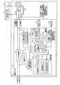
図1は、本発明にかかる実施の形態1のPLCの構成例を示す図である。図示するように、PLC1は、産業用機器を制御するPLC1の動作を統括的に制御するCPUユニット20、PLC1にネットワーク接続機能を付与するためのサブユニットであるネットワークユニット30、CPUユニット20とサブユニットとの間でデータ転送を行うためのPLCバス40、および交流の商用電源から各構成要素(CPUユニット20、ネットワークユニット30、PLCバス40)を駆動する直流の内部電源を生成する電源ユニット10とを備えている。なお、実際には、PLCバス40は上述の3つのユニットとは異なるベースユニットと呼ばれる別のユニットに内蔵されており、このベースユニットに電源ユニット10、CPUユニット20およびネットワークユニット30を装着することによってPLC1が構成される。なお、ベースユニットは、詳しく説明しないが、ネットワークユニット30のほかにも種々の機能を有するサブユニットが装着されるようになっており、目的に合わせて所望のサブユニットが選択されて装着される。Embodiment 1 FIG.
FIG. 1 is a diagram illustrating a configuration example of the PLC according to the first embodiment of the present invention. As shown in the figure, the PLC 1 includes a CPU unit 20 that comprehensively controls the operation of the PLC 1 that controls industrial equipment, a
本発明の実施の形態1では、電源ユニット10は、商用電源からの入力電流、入力電圧および入力有効電力(入力電力)と、内部電源としての出力電圧および出力電流と、電源ユニット10内の平均温度(装置内温度)と、PLC1の周囲の温度(装置周囲温度)と、変換効率ηと、力率φとを出力する(以降、以上に列挙した出力情報を入力電流等と総称する)。PLC1は、ネットワークユニット30を介して外部機器としての他のPLC2が接続され、CPUユニット20にデバイスメモリの中身を表示する等の機能を備える外部機器としてのプログラマブル表示器3が接続されている。電源ユニット10が出力した入力電流等はいったんCPUユニット20に送られた後、プログラマブル表示器3から監視することができる。また、CPUユニット20に送られた入力電流等はPLCバス40およびネットワークユニット30を介して他のPLC2から監視することができる。 In Embodiment 1 of the present invention, the
電源ユニット10は、VTやCTなど大型で高価な部品を使用することなく入力電流を求めるために、入力電流を直接測定するのではなく、出力電流および出力電源を測定し、測定したこれらの値と効率ηおよび力率φとから以下の関係式を用いて入力電力および入力電流を求める。
入力電力=出力電圧×出力電流/効率η (1)
入力電流=入力電力/(入力電圧×力率φ) (2)The
Input power = output voltage x output current / efficiency η (1)
Input current = input power / (input voltage × power factor φ) (2)
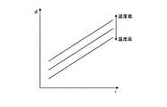
ここで、電源ユニット10の効率ηおよび力率φは、環境温度に応じて変化する。図2は、効率ηの温度依存性の一例を説明する図であり、図3は力率φの温度依存性の一例を説明する図である。図2および図3の横軸は電流iを示している。これらの図に示すように、効率ηは温度が高いほど大きくなり、力率φは温度が低いほど大きくなる特性を有している。本発明の実施の形態1では、できるだけ精確に入力電力および入力電流を求めるために、効率ηと環境温度(および電流)との対応関係を記述したデータ(変換効率データ111)および力率φと環境温度(および電流)との対応関係を記述したデータ(力率データ112)とを記憶しており、電源ユニット10は上式(1)および(2)に適用する効率ηおよび力率φをこれらのデータに基づいて求めるようにした。なお、変換効率データ111および力率データ112に記述されている対応関係において、環境温度は装置周囲温度、電流は出力電流が夫々採用されている。 Here, the efficiency η and the power factor φ of the
図1に戻り、電源ユニット10は、AC/DC変換器11、出力電圧測定部12、負荷電流測定部13、温度センサ14、入力電圧検出信号生成部15、記憶装置16、演算部17、通信インタフェース(I/F)18、および表示部19を備えている。 Returning to FIG. 1, the
AC/DC変換器11は、入力された商用電源を内部電源に変換する。なお、本図では、わかりやすくするために、商用電源の入力を入力電流と入力電圧とに分けて描画しており、内部電源の出力を出力電流と出力電圧とに分けて描画している。内部電源はCPUユニット20、PLCバス40、およびネットワークユニット30に供給される。 The AC /
出力電圧測定部12は、AC/DC変換器11からの出力電圧を測定し、測定した出力電圧のアナログ測定値を演算部17に送る。負荷電流測定部13は、AC/DC変換器11からの出力電流、すなわちCPUユニット20等で消費された電流の合計である負荷電流を測定し、測定した負荷電流のアナログ値を演算部17に送る。負荷電流測定部13は、例えば小さな負荷抵抗を電流が出力される配線上に介挿して当該負荷抵抗の両端にかかる電圧を測定するなど、簡易な方法で電流を測定することができる。 The output
温度センサ14は、例えば熱電対やサーミスタにより構成される。一般に、電源装置(スイッチングレギュレータを含む)の損失は、概ねスイッチング素子によるが、その他装置内部品(FET、ダイオード、シャント抵抗、ダミー抵抗、LCフィルタ、スナバ回路、トランス、ブリッジダイオードなど)でも多数損失要因が存在し、しかも部品毎に温度依存性がある。つまり、電源装置内の温度は測定箇所によっておおきくばらつく。したがって、電源装置の効率η(=100−装置全体の総損失[%])を求めるためには、スイッチング素子のような部分的な温度測定ではなく、電源装置全体の温度を精度よく求める必要がある。ここでは、温度センサ14は電源ユニット10内の複数ポイントに配設され、各ポイントの温度検出値の平均を求める。そして、電源ユニット10の装置内温度を当該平均温度で代表させる。 The
図4−1および図4−2は、ともに温度センサ14の配置例を説明する図である。図4−1は電源ユニット10内の基板部品面を上面からみた図であり、図4−2は電源ユニット10の内部の斜視図である。PLC1は、基板部品面が制御盤に平行になるように設置され、結果として図4−2に示すように基板部品面の垂線が地面にたいして平行になる。図4−2の上面、下面および左面には、熱を排出するための通風孔が設けられており(図示せず)、主に対流によって下面から上面へ抜ける空気によって基板上の各部品が冷却される。したがって、上面に近いほど温度が高くなる。精度よく装置内温度を測定するために、図4−2の上下方向に3つの温度センサ14が等間隔に設けられている。また、図4−1に示すように図4−2の前後方向にも夫々3つずつ温度センサ14が等間隔に設けられており、基板部品面には合計9個の温度センサ14が設けられている。装置内温度は、これらの9個の温度センサ14による検出値を平均することにより求められる。4A and 4B are diagrams for explaining an arrangement example of the
なお、変換効率データ111および力率データ112を作成する際、装置内温度毎に効率ηおよび力率φを測定するよりも、装置周囲温度毎に測定するほうが簡単である。そこで、変換効率データ111および力率データ112は、前述のように、夫々、環境温度として装置周囲温度を採用し、効率η、力率φを求めるための装置周囲温度は装置内温度から推定するものとする。装置周囲温度を算出するための構成については後ほど明らかになる。 When generating the
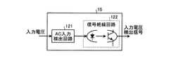
入力電圧検出信号生成部15は、入力電圧を算出するために用いられる入力電圧検出信号を生成する。図5は、入力電圧検出信号生成部15のさらに詳細な構成を説明する図である。図示するように入力電圧検出信号生成部15は、AC入力検出回路121とフォトカプラなどにより構成される信号絶縁回路122とを備えている。AC入力検出回路121は、入力電圧を検出し、検出した交流の入力電圧波をダイオードブリッジなどにより全波整流波に整流し、さらに当該全波整流波の大きさを調整して信号絶縁回路122に入力する。信号絶縁回路122は、入力された全波整流波からパルス信号を生成し、生成したパルス信号を入力電圧検出信号として出力する。これにより、入力電圧検出信号生成部15は、AC入力検出回路121による調整比率と信号絶縁回路122がパルス波形の立ち上がりを出力するしきい値とにより決まる電圧値Vをしきい値とし、入力電圧の波形の振れ幅がしきい値Vを越えたときにONとなるパルス信号を出力することになる。 The input voltage detection
図6は、入力電圧波、全波整流波、および入力電圧検出信号の波形を説明する図である。図示するように、入力電圧波の振幅をVa、周波数をF、入力電圧波が0からVまで上昇するまでの時間をT、入力電圧検出信号のOFF時間をToff、入力電圧検出信号の周期をFbとすると、以下の関係が成り立つ。なお、前述したように、Vは信号絶縁回路122により入力電圧検出信号のパルスが立ち上がるためのしきい値電圧である。
Toff=2T (3)
F=2Fb (4)
V=Va×Sin(2πFT) (5)FIG. 6 is a diagram illustrating waveforms of an input voltage wave, a full wave rectified wave, and an input voltage detection signal. As shown in the figure, the amplitude of the input voltage wave is Va, the frequency is F, the time until the input voltage wave rises from 0 to V is T, the OFF time of the input voltage detection signal is Toff, and the period of the input voltage detection signal is Assuming Fb, the following relationship is established. As described above, V is a threshold voltage for the pulse of the input voltage detection signal to rise by the
Toff = 2T (3)
F = 2Fb (4)
V = Va × Sin (2πFT) (5)
したがって、入力電圧波の振幅Vaは、
Va=V/Sin(2π・Fb・Toff) (6)
により簡単に求めることができる。Therefore, the amplitude Va of the input voltage wave is
Va = V / Sin (2π · Fb · Toff) (6)
Can be easily obtained.
図1に戻り、記憶装置16は、例えばROM(Read Only Memory)により構成され、変換効率データ111、力率データ112、温度相関データ113、および入力電圧算出用データ114が予め格納されている。 Returning to FIG. 1, the
変換効率データ111は、効率ηと出力電流と装置周囲温度との関係を記述したテーブル構成のデータであって、出力電流の値と装置周囲温度とを指定して参照することによって効率ηを読み出すことができるものである。力率データ112は、力率φと出力電流と装置周囲温度の関係を記述したテーブル構成のデータであって、出力電流と装置周囲温度とを指定して参照することによって力率φを読み出すことができるものである。 The
温度相関データ113は、装置内温度と装置周囲温度との対応付けを記述したテーブル構成のデータである。 The
入力電圧算出用データ114は、入力電圧検出信号から入力電圧を求めるためのテーブルである。入力電圧の振幅Vaは、V、Fb、Toffとの間で式(6)の関係がある。また、入力電圧の実効値は振幅Vaを2の平方根で除算することにより求められる。入力電圧算出用データ114は、式(6)を演算しなくてもよいようにV、Fb、Toffおよび入力電圧(実効値)の間の関係を記述したテーブル形式のデータ構造を備えており、例えば図7に示すものである。以降、入力電圧、入力電流は特に断りがなくても夫々実効値を指しているものとする。 The input
演算部17は、出力電圧測定部12が検出した出力電圧値、負荷電流測定部13が測定した出力電流値、複数の温度センサ14が夫々検出した温度に対応する測定値(温度検出値)、入力電圧検出信号生成部15が生成した入力電圧信号と、記憶装置16に格納されているデータとに基づいて入力電流等を算出する。 The
演算部17は、例えばマイクロコンピュータにより構成される。具体的には、演算部17は、CPU(Central Processing Unit)101、ROM102、RAM(Random Access Memory)103、AD(Analog Digital)変換回路104、およびI/Oポート105を備えている。 The calculating
ROM102には、入力電力等を算出するためのコンピュータプログラムである電力監視プログラム106が格納されている。AD変換回路104は、アナログ値として入力される出力電圧値、出力電流値、複数の温度検出値、および入力電圧検出信号をデジタル値に変換する。I/Oポート105は記憶装置16にアクセスするためのインタフェースである。CPU101は電力監視プログラム106をROM102から読み出して実行することによって後述の各種機能部として実現する。CPU101は、入力電力等を算出するために、AD変換回路104から各種測定値を取得し、I/Oポート105を介して記憶装置16から各種データを読み出す。RAM103は、CPU101が入力電力等を算出するためのワークエリアとして用いられる。 The
通信I/F18は、演算部17が算出した入力電流等をCPUユニット20に送るための接続インタフェースである。 The communication I /
表示部19は、演算部17が算出した入力電流等を表示出力するための表示装置であって、例えば小型の液晶ディスプレイや7セグメントディスプレイなどにより構成される。 The
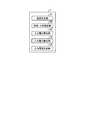
図8は、CPU101が電力監視プログラム106を実行することによって実現する機能部を説明する図である。図示するように、演算部17は、複数の温度センサ14による温度検出値および温度相関データ113に基づいて装置内温度および装置周囲温度を算出する温度算出部131と、算出された装置周囲温度、出力電流値、変換効率データ111および力率データ112に基づいて効率ηおよび力率φを算出する効率・力率算出部132と、入力電圧検出信号と入力電圧算出用データ114に基づいて入力電圧を算出する入力電圧算出部133と、出力電流値、出力電圧値および算出した効率ηに基づいて入力電力を算出する入力電力算出部134と、算出した入力電力、力率φおよび入力電圧に基づいて入力電流を参照する入力電流算出部135と、を備えている。 FIG. 8 is a diagram illustrating functional units realized by the
図9は、本発明の実施の形態1の電源ユニット10が入力電流等を算出する動作を説明する図である。図示するように、温度算出部131は、電源ユニット10内の温度検出値を取得し(ステップS1)、取得した温度検出値の平均をとって装置内温度を算出する(ステップS2)。そして、温度算出部131は、温度相関データ113を用いて装置内温度を装置周囲温度に変換する(ステップS3)。装置内温度、装置周囲温度は、RAM103内のワークエリアに一時的に格納される。なお、装置内温度、装置周囲温度だけでなく以降のステップにて算出される入力電流等は全て当該ワークエリアに一時的に格納され、演算時等に適宜読み出される。 FIG. 9 is a diagram illustrating an operation in which the
一方、効率・力率算出部132は、出力電圧値、出力電流値を取得する(ステップS4)。そして、効率・力率算出部132は、算出された装置周囲温度と出力電流値とに基づいて効率ηおよび力率φを求める(ステップS5)。具体的には、効率・力率算出部132は、変換効率データ111を参照して、算出された装置周囲温度および取得した出力電流値に対応する効率ηを求め、力率データ112を参照して、装置周囲温度および出力電流値に対応する力率φを求める。 On the other hand, the efficiency / power
入力電圧算出部133は、入力電圧検出信号を取得する(ステップS6)。なお、取得した入力電圧検出信号は、時系列的にRAM103に蓄積記憶されるものとする。入力電圧算出部133は、取得した入力電圧信号と入力電圧算出用データ114とに基づいて入力電圧を求める(ステップS7)。具体的には、入力電圧算出部133は、RAM103に蓄積記憶されている入力電圧信号から、パルス波形の周期FbおよびOFF時間Toffを求める。そして、求めたFbおよびToffとしきい値電圧Vとを検索キーとして入力電圧算出用データ114を検索し、入力電圧(実効値)を求める。 The input
入力電力算出部134は、算出された出力電圧と出力電流と効率ηとを式(1)に適用して入力電力を求める(ステップS8)。入力電流算出部135は、求めた入力電力と入力電圧と力率φとを式(2)に適用して入力電流を求める(ステップS9)。演算部17は、以上のステップにより求めた装置内温度、装置周囲温度、入力電流、入力電圧、入力電力、出力電流、出力電圧、効率ηおよび力率φを、表示部19へ、および通信I/F18を介してCPUユニット20へ、出力し(ステップS10)、動作が終了となる。なお、ステップS1〜ステップS10の動作は所望の時間間隔またはタイミングで繰り返し実行される。CPUユニット20に出力された入力電流等はプログラマブル表示器3に送られる。また、入力電流等は、PLCバス40、ネットワークユニット30を介してPLC2へ送られる。 The input
なお、ステップS1〜ステップS10の処理の順番は一例であって、処理の順番はこの通りと同じに限定されない。 In addition, the order of the process of step S1-step S10 is an example, Comprising: The order of a process is not limited to the same as this.
また、本発明の第1の実施の形態では、PLC1が機能毎に電源ユニット10、CPUユニット20、ネットワークユニット30、PLCバス40に分けられているものとして説明したが、これらの構成要素が一体として構成されていてもよい。 In the first embodiment of the present invention, the PLC 1 is described as being divided into the
また、AC入力検出回路121は、入力電圧波を全波整流波に整流するとして説明したが、半波整流波に整流するようにしてもよい。この場合、式(3)を下式(7)、式(4)を下式(8)に置き換えるとよい。
T=Toff−1/(2・Fb) (7)
F=Fb (8)
また、AC入力検出回路121は、整流を行わないで波高の調整のみを行うようにしてもよい。その場合、信号絶縁回路122はプラス極側の信号しか拾わないので、上記式(7)、(8)を用いることができる。Further, although the AC
T = Toff−1 / (2 · Fb) (7)
F = Fb (8)
Further, the AC
また、変換効率データ111および力率データ112に記述されている対応関係において、温度は装置周囲温度、電流は出力電流が夫々採用されているとして説明したが、温度は装置内温度が採用されるようにしても構わない。 Further, in the correspondence relationship described in the
このように、本発明の実施の形態1によれば、環境温度としての装置周囲温度または装置内温度の測定値と、記憶装置16に予め記憶しているAC/DC変換器11の変換効率ηと環境温度との対応付けを記録した変換効率データ111とに基づいて変換効率ηを求め、求めた変換効率ηと、測定した出力電圧および出力電流とを用いて入力電力を算出するようにしたので、できるだけ精確に入力電力を測定することができるようになる。 As described above, according to the first embodiment of the present invention, the measured value of the device ambient temperature or the device internal temperature as the environmental temperature, and the conversion efficiency η of the AC /
また、環境温度の測定値と記憶装置16に予め記憶しているAC/DC変換器11の力率φと環境温度との対応付けを記録した変換効率データ111とに基づいて力率φを求め、AC/DC変換器11へ入力された商用電源の入力電圧をさらに測定し、力率φ、効率η、入力電圧、出力電圧、出力電流を用いて入力電流を算出するようにしたので、できるだけ精確に入力電流を測定することができるようになる。 Further, the power factor φ is obtained based on the measured value of the environmental temperature and the
また、電源ユニット10内の複数ポイントに温度センサ14を備え、当該複数の温度センサ14による温度検出値から環境温度を算出するようにしたので、部品毎の温度のばらつきおよび温度上昇率のばらつきに過度に影響されることのなく環境温度を測定することができ、結果としてより精確に入力電力を測定することができる。Further, a
また、環境温度は、複数の温度センサ14による温度検出値の平均値である。 The environmental temperature is an average value of temperature detection values obtained by the plurality of
または、環境温度は、PLC1の周囲温度の推定値であって、予め記憶装置16に記憶された温度検出値の平均値とPLC1の周囲温度との対応関係を記録した温度相関データに基づいて環境温度の測定値を得るようにしたので、事前に変換効率データ111を作成することが容易になる。 Alternatively, the environmental temperature is an estimated value of the ambient temperature of the PLC 1 and is based on temperature correlation data in which a correspondence relationship between the average value of the temperature detection values stored in advance in the
また、変換効率データ111は、効率ηと環境温度と出力電流との対応付けを記録したデータであって、力率データ112は、力率φと環境温度と出力電流との対応付けを記録したデータであって、環境温度の測定値と出力電流の測定値と変換効率データ111とに基づいて変換効率ηを求め、環境温度の測定値と出力電流の測定値と力率データ112とに基づいて力率φを求めるようにしたので、効率η、力率φの出力電流に応じた変化も考慮に入れて入力電流、入力電力を算出することができるので、より精確に入力電流、入力電力を算出することができる。 The
また、入力側と出力側とが電気的に絶縁されている信号絶縁回路を用いて、入力電圧波において入力された電圧値が所定のしきい値V以上のときオンとなるパルス波を生成し、生成したパルス波に基づいて入力電圧を算出するようにしたので、絶縁状態で、かつ簡単に入力電圧を測定することができる。 In addition, a signal isolation circuit in which the input side and the output side are electrically isolated is used to generate a pulse wave that is turned on when the input voltage value is greater than or equal to a predetermined threshold value V. Since the input voltage is calculated based on the generated pulse wave, the input voltage can be easily measured in an insulated state.
また、入力電力または入力電流を表示出力する表示部19をさらに備えるようにしたので、ユーザはその場で入力電力または入力電流を確認することができるようになる。 In addition, since the
また、入力電力または入力電流をPLC1に接続された外部機器としてのプログラマブル表示器3やPLC2に出力する外部出力部としてのCPUユニット20、ネットワークユニット30およびPLCバス40を備えるように構成したので、ユーザは遠隔地において入力電力または入力電流を確認することができるようになる。In addition, since it is configured to include the CPU unit 20, the
実施の形態2.
実施の形態1では、PLC1の取り付け方向は固定となっており、図4−2に示すように、基板部品面が制御盤に平行になるようにPLC1が取り付けられるものとして説明した。このようなPLC1では、例えば上下逆に取り付けられるなど、取り付け方向が想定されている方向と異なる場合、装置内の空気の流れが変わるため、各温度センサ14による温度検出値が変わる。そして、装置内温度が意図した値と異なり、結果として入力電力等を精確に求めることができなくなってしまう。そこで、実施の形態2では、取り付け方向毎に装置内温度の算出値と装置周囲温度との間の関係を記述した温度相関データを用意することによって、どのような取り付け方向で設置されても入力電流等を精確に求めることができるようにした。Embodiment 2. FIG.
In the first embodiment, the mounting direction of the PLC 1 is fixed, and as described in FIG. 4B, the PLC 1 is mounted so that the board component surface is parallel to the control panel. In such a PLC 1, for example, when the mounting direction is different from the assumed direction, such as mounting upside down, the flow of air in the apparatus changes, so that the temperature detection value by each
実施の形態2のPLCに含まれる電源ユニット以外の構成要素は実施の形態1と同等であるため、電源ユニット50以外の構成要素については同一の名称および符号を使用し、重複する説明を省略する。また、実施の形態2の電源ユニットの構成要素で実施の形態1と同一の機能を有するものには同一の名称および符号を使用し、詳細な説明を省略する。 Since the components other than the power supply unit included in the PLC of the second embodiment are the same as those of the first embodiment, the same names and reference numerals are used for the components other than the
図10は、実施の形態2の電源ユニットの実施の形態1と異なる構成を説明する図である。図示するように、電源ユニット50は、記憶装置16に替えて記憶装置56、演算部17に替えて演算部57を備えている。記憶装置56は、変換効率データ111、力率データ112、想定される取り付け方向毎に用意される温度相関データ143(温度相関データ143a、143b、・・・、143n)、入力電圧算出用データ114が予め格納されている。 FIG. 10 is a diagram illustrating a configuration different from that of the first embodiment of the power supply unit of the second embodiment. As illustrated, the
演算部57は、温度算出部151、効率・力率算出部132、入力電圧算出部133、入力電力算出部134、および入力電流算出部135を備えている。温度算出部151は、装置内温度から装置周囲温度を算出する際、温度相関データ143a〜nのうちPLC1の取り付け方向に応じた温度相関データを選択し、選択した温度相関データを用いて装置周囲温度を算出する。なお、取り付け方向は、ユーザによる設定により与えられるようにしてもよいし、当該取り付け方向を検出する機構を搭載し、当該機構から与えられるようにしてもよい。 The calculation unit 57 includes a
実施の形態2の電源ユニット50の動作は、実施の形態1において説明したステップS3の処理において温度相関データを選択する動作が加わるだけで他は同じであるので、ここでは説明を省略する。 The operation of the
このように、本発明の実施の形態2によれば、記憶装置56に自PLC1の設置方向毎に作成された複数の温度相関データ143を予め記憶させておき、当該複数の温度相関データのうちの使用する温度相関データを自PLC1の設置方向に応じて変更するようにしたので、PLC1の設置方向が変わっても精確に入力電力等を算出することができる。Thus, according to the second embodiment of the present invention, the
実施の形態3.
変換効率データ111は、効率ηと装置周囲温度との対応付けを記述したテーブル構成を有している。その対応付けは、一般に、所定の刻み幅毎に記述される。刻み幅が細かいほど、効率ηと装置周囲温度との対応関係が精確に表現される。また、装置周囲温度は、温度相関データ113により装置内温度(温度センサ14の検出値の平均温度)と一対一で対応づけられている。一方で、部品の温度依存性の大きさと部品の効率ηに与える影響の大きさとの間には正の相関がある。また、温度依存性が大きい部品は発熱しやすく、その部品の近傍ほど温度が上がりやすい。そこで、実施の形態3では、演算部は、近傍の部品による効率ηに対する影響が大きい温度センサ14ほど検出値の変化を装置内温度として算出される値に大きく反映させることができるように、温度センサ14の検出値の重み付け平均を装置内温度とするようにした。これにより、演算部は、効率ηに与える影響が大きい部品の近傍の温度検出値に対しては細かい刻み幅で効率ηを算出でき、効率ηに与える影響が小さい部品の近傍の温度検出値に対しては大きい刻み幅で効率ηを算出できる。結果として、演算部は、電源ユニット内に均等に配置された温度センサ14の単純平均を装置内温度とする場合に比べ、より精確に入力電力を求めることができるようになる。Embodiment 3 FIG.
The
実施の形態3のPLCに含まれる電源ユニット以外の構成要素は実施の形態1と同等であるため、電源ユニット以外の構成要素については同一の名称および符号を使用し、重複する説明を省略する。また、実施の形態3の電源ユニットの構成要素で実施の形態1と同一の機能を有するものには同一の名称および符号を使用し、詳細な説明を省略する。 Since components other than the power supply unit included in the PLC of the third embodiment are the same as those of the first embodiment, the same names and reference numerals are used for the components other than the power supply unit, and redundant description is omitted. Further, the same names and symbols are used for the components of the power supply unit of the third embodiment having the same functions as those of the first embodiment, and detailed description thereof is omitted.
図11は、実施の形態3の電源ユニットの実施の形態1と異なる構成を説明する図である。図示するように、電源ユニット60は、記憶装置16に替えて記憶装置66、演算部17に替えて演算部67を備えている。記憶装置66は、変換効率データ111、力率データ112、温度相関データ113、入力電圧算出用データ114、および係数データ615が予め格納されている。 FIG. 11 is a diagram illustrating a configuration different from that of the first embodiment of the power supply unit of the third embodiment. As illustrated, the
係数データ615は、図4−1に示した9個の温度センサ14の夫々と重み付け係数とを対応づけて記述したデータである。係数データ615においては、近傍の部品が効率ηに与える影響が大きい温度センサ14ほど、大きい値の重み付け係数が対応づけられている。効率ηに対する影響が他の部品よりも大きい部品とは、例えば、FET、トランス、シャント抵抗、ダイオードがある。これらの中でも、FETおよびトランスは、シャント抵抗やダイオードよりも効率ηに与える影響が大きい。即ち、重み付け係数の大きさは、(FET、トランスの近傍の温度センサ14)>(シャント抵抗、ダイオードの近傍の温度センサ14)>(その他の温度センサ14)となる。 The
演算部67は、温度算出部631、効率・力率算出部132、入力電圧算出部133、入力電力算出部134、および入力電流算出部135を備えている。 The
温度算出部631は、係数データ615を用いて9個の温度センサ14の検出値の重み付け平均を算出し、算出した重み付け平均を装置内温度とする。そして、温度相関データ113を参照して、前記求めた装置内温度に対応する装置周囲温度を算出する。 The
実施の形態3の電源ユニット60の動作は、実施の形態1において説明したステップS2の処理において、温度算出部631が係数データ615に記述されている温度センサ14毎の重み付け係数を用いて重み付け平均を算出するだけで他は同じであるので、ここでは説明を省略する。 In the operation of the
このように、本発明の実施の形態3によれば、温度算出部631は効率ηに与える影響が大きい部品の近傍の温度測定値ほど重み付け係数が大きくなるように温度センサ14の測定値の重み付け平均を算出し、算出した値を装置内温度とする、ように構成したので、演算部67は、効率ηに与える影響が大きい部品の近傍の温度検出値に対しては細かい刻み幅で効率ηを算出し、効率ηに与える影響が小さい部品の近傍の温度検出値に対しては大きい刻み幅で効率ηを算出することができる。結果として、演算部67は、電源ユニット内に均等に配置された温度センサ14の単純平均を装置内温度とする場合に比べ、より精確に入力電力を求めることができるようになる。 As described above, according to the third embodiment of the present invention, the
なお、効率ηの場合と同様に、部品の温度依存性の大きさと部品が力率φに与える影響の大きさとの間にも正の相関関係がある。したがって、温度算出部631が、温度センサ14の検出値の重み付け平均を装置内温度とすることにより、力率φに与える影響が大きい部品の近傍の温度検出値に対しては細かい刻み幅で力率φが算出され、力率φに与える影響が小さい部品の近傍の温度検出値に対しては大きい刻み幅で力率φが算出される。 As in the case of efficiency η, there is a positive correlation between the magnitude of the temperature dependence of the part and the magnitude of the influence of the part on the power factor φ. Therefore, the
実施の形態4.
実施の形態3においては、演算部67が夫々の温度センサ14の値の検出値の重み付け平均を装置内温度とすることによって入力電力の算出精度を向上させるようにしたが、温度センサ14の配設位置を工夫することによっても実施の形態3と同様の効果を得ることができる。実施の形態4のPLCの構成は、温度センサ14の配設位置を除いて実施の形態1と同等であるので、温度センサ14の配設位置のみ説明して重複する説明を省略する。Embodiment 4 FIG.
In the third embodiment, the
図12−1および図12−2は、ともに温度センサ14の実施の形態4の配置例を説明する図である。図12−1は電源ユニット10内の基板部品面を上面からみた図である。図示するように、効率ηに大きく影響するトランス、FET、シャント抵抗、ダイオードが集中的に配置されている部分には、温度センサ14が集中的に配設され(温度センサ設置位置14a)、その他の部位には温度センサ設置位置14aよりも大きな間隔を空けて温度センサ14が配設されている(温度センサ設置位置14b)。図12−2は電源ユニット10の内部の斜視図である。図12−2においては、簡単のため、FET、シャント抵抗、ダイオードの描画を省略している。図12−1および図12−2に示すように、温度センサ設置位置14aの密度は温度センサ設置位置14bの倍の密度となっている。 12A and 12B are diagrams for explaining an arrangement example of the
温度算出部131は、温度センサ設置位置14a、14bにおける温度センサ14の検出値を単純平均することによって装置内温度を算出する。効率ηに与える影響が大きい部品ほど近傍に多くの温度センサ14が配設されているため、温度算出部131は、これらの温度センサ設置位置14a、14bにおける温度センサ14の検出値の単純平均を算出することによって、電源ユニット内に均等に配置された温度センサ14の検出値の重み付け平均を算出した場合と同じ値を得ることができる。即ち、演算部17は、効率ηに与える影響が大きい部品の近傍の温度検出値に対しては細かい刻み幅で効率ηを算出し、効率ηに与える影響が小さい部品の近傍の温度検出値に対しては相対的に大きい刻み幅で効率ηを算出することができる。 The
このように、本発明の実施の形態4によれば、効率ηに与える影響が大きい部品ほど近傍に多くの温度センサが配設されるようにしたので、実施の形態3と同様に、演算部17は、電源ユニット内に均等に配置された温度センサ14の単純平均を装置内温度とする場合に比べ、より精確に入力電力を求めることができるようになる。 As described above, according to the fourth embodiment of the present invention, a part having a larger influence on the efficiency η is arranged with more temperature sensors in the vicinity thereof. 17, the input power can be obtained more accurately as compared with the case where the simple average of the
なお、実施の形態1〜4の説明においては、本発明の実施の形態のコントローラをPLCに適用した場合について説明したが、本発明の実施の形態のコントローラを適用可能なコントローラはPLCだけに限定されない。例えば交流の商用電源からいったん直流電源を生成し、生成した直流電源から所望の交流電源を生成するインバータや、商用電源から直流電源を生成し、生成した直流電源を用いてモータを駆動するサーボアンプなど、AC/DC変換器を備えるコントローラに適用することができる。また、本発明の実施の形態が適用された電源装置はコントローラから分離不可能に構成されていてもよい。 In the description of the first to fourth embodiments, the case where the controller of the embodiment of the present invention is applied to the PLC has been described. However, the controller to which the controller of the embodiment of the present invention can be applied is limited to the PLC. Not. For example, an inverter that once generates a DC power supply from an AC commercial power supply and generates a desired AC power supply from the generated DC power supply, or a servo amplifier that generates a DC power supply from the commercial power supply and drives the motor using the generated DC power supply The present invention can be applied to a controller including an AC / DC converter. Moreover, the power supply device to which the embodiment of the present invention is applied may be configured so as not to be separated from the controller.
以上のように、本発明にかかる電源装置およびコントローラは、AC/DC変換器を有する電源装置およびAC/DC変換器を有するコントローラに適用して好適である。 As described above, the power supply device and the controller according to the present invention are suitable for application to a power supply device having an AC / DC converter and a controller having an AC / DC converter.
1、2 PLC
3 プログラマブル表示器
10、50、60 電源ユニット
11 AC/DC変換器
12 出力電圧測定部
13 負荷電流測定部
14 温度センサ
14a、14b 温度センサ設置位置
15 入力電圧検出信号生成部
16、56、66 記憶装置
17、57、67 演算部
18 通信I/F
19 表示部
20 CPUユニット
30 ネットワークユニット
40 PLCバス
101 CPU
102 ROM
103 RAM
104 AD変換回路
105 I/Oポート
106 電力監視プログラム
111 変換効率データ
112 力率データ
113、143、143a〜n 温度相関データ
114 入力電圧算出用データ
121 AC入力検出回路
122 信号絶縁回路
131、151、631 温度算出部
132 効率・力率算出部
133 入力電圧算出部
134 入力電力算出部
135 入力電流算出部
615 係数データ1, 2 PLC
3
19 Display Unit 20
102 ROM
103 RAM
104 AD conversion circuit 105 I /
Claims (18)
Translated fromJapanese前記AC/DC変換器が出力した直流電源の出力電圧を測定する出力電圧測定部と、
前記AC/DC変換器が出力した直流電源の出力電流を測定する出力電流測定部と、
環境温度を測定する温度測定部と、
前記AC/DC変換器の変換効率ηと前記環境温度との対応付けを記録した変換効率データを予め記憶する記憶装置と、
前記温度測定部による環境温度の測定値と前記変換効率データとに基づいて変換効率ηを求め、前記求めた変換効率ηと、前記出力電圧測定部による出力電圧の測定値と、前記出力電流測定部による出力電流の測定値と、を用いて前記AC/DC変換器へ入力された商用電源の入力電力を算出し、前記算出した入力電力を出力する演算部と、
を備えることを特徴とする電源装置。An AC / DC converter that takes an AC commercial power supply as input and generates and outputs a DC power supply;
An output voltage measuring unit for measuring an output voltage of a DC power source output from the AC / DC converter;
An output current measuring unit for measuring an output current of a DC power source output from the AC / DC converter;
A temperature measuring unit for measuring the environmental temperature;
A storage device that stores in advance conversion efficiency data in which the correspondence between the conversion efficiency η of the AC / DC converter and the environmental temperature is recorded;
The conversion efficiency η is obtained based on the measured value of the environmental temperature by the temperature measuring unit and the conversion efficiency data, the obtained conversion efficiency η, the measured value of the output voltage by the output voltage measuring unit, and the output current measurement A calculation unit that calculates the input power of the commercial power source input to the AC / DC converter using the measured value of the output current by the unit, and outputs the calculated input power;
A power supply apparatus comprising:
入力電力=出力電圧×出力電流/変換効率η
の関係式を用いて前記入力電力を算出する、
ことを特徴とする請求項1に記載の電源装置。The computing unit is
Input power = output voltage x output current / conversion efficiency η
The input power is calculated using the relational expression of
The power supply device according to claim 1.
前記記憶装置は、前記AC/DC変換器の力率φと環境温度との対応付けを記録した力率データを予め記憶し、
前記演算部は、前記温度測定部による環境温度の測定値と前記力率データとに基づいて力率φを求め、前記求めた変換効率ηおよび力率φと、前記出力電圧測定部による出力電圧の測定値と、前記出力電流測定部による出力電流の測定値と、前記入力電圧測定部による入力電圧の測定値と、を用いて前記AC/DC変換器へ入力された商用電源の入力電流を算出し、前記算出した入力電流を出力する、
ことを特徴とする請求項1に記載の電源装置。An input voltage measuring unit for measuring an input voltage of a commercial power source input to the AC / DC converter;
The storage device stores in advance power factor data in which the correspondence between the power factor φ of the AC / DC converter and the ambient temperature is recorded,
The calculation unit obtains a power factor φ based on the measured value of the environmental temperature by the temperature measurement unit and the power factor data, the obtained conversion efficiency η and power factor φ, and the output voltage by the output voltage measurement unit The measured value of the output current, the measured value of the output current by the output current measuring unit, and the measured value of the input voltage by the input voltage measuring unit are used to calculate the input current of the commercial power source input to the AC / DC converter. Calculate and output the calculated input current,
The power supply device according to claim 1.
入力電流=出力電圧×出力電流/(入力電圧×変換効率η×力率φ)
の関係式を用いて前記入力電流を算出する、
ことを特徴とする請求項3に記載の電源装置。The computing unit is
Input current = output voltage x output current / (input voltage x conversion efficiency η x power factor φ)
The input current is calculated using the relational expression of
The power supply device according to claim 3.
を備えることを特徴とする請求項1に記載の電源装置。The temperature measurement unit includes temperature sensors provided at a plurality of points in the power supply device, a temperature calculation unit that calculates a measurement value of the environmental temperature from temperature detection values by the plurality of temperature sensors,
The power supply device according to claim 1, further comprising:
ことを特徴とする請求項5に記載の電源装置。The measured value of the environmental temperature is an average value of temperature detection values by the plurality of temperature sensors.
The power supply device according to claim 5.
ことを特徴とする請求項5に記載の電源装置。The measurement value of the environmental temperature is a weighted average of temperature detection values of the plurality of temperature sensors, and a temperature sensor having a greater influence of neighboring components on the conversion efficiency η has a larger weighting coefficient.
The power supply device according to claim 5.
前記記憶装置は、前記複数の温度センサによる温度検出値の平均値と自電源装置が搭載される機器の周囲温度との対応関係を記述した温度相関データを予め記憶し、
前記温度算出部は、前記複数の温度センサによる温度検出値の平均値を算出し、前記算出した温度検出値の平均値と前記温度相関データとに基づいて環境温度の測定値を算出する、
ことを特徴とする請求項5に記載の電源装置。The measured value of the environmental temperature is an estimated value of the ambient temperature of the device in which the power supply device is mounted,
The storage device stores in advance temperature correlation data describing a correspondence relationship between an average value of temperature detection values by the plurality of temperature sensors and an ambient temperature of a device on which the power supply device is mounted,
The temperature calculation unit calculates an average value of temperature detection values by the plurality of temperature sensors, and calculates a measured value of the environmental temperature based on the calculated average value of the temperature detection values and the temperature correlation data.
The power supply device according to claim 5.
ことを特徴とする請求項9に記載の電源装置。The storage device stores in advance a plurality of temperature correlation data created for each installation direction of a device on which the power supply device is mounted, and the temperature calculation unit stores a plurality of temperature correlation data stored in the storage device. Change the temperature correlation data to be used according to the installation direction of the equipment on which the power supply is installed.
The power supply device according to claim 9.
前記力率データは、前記AC/DC変換器の力率φと環境温度と前記AC/DC変換器の出力電流との対応付けを記録したデータであって、
前記演算部は、前記温度測定部による環境温度の測定値と前記出力電流測定部による出力電流の測定値と前記変換効率データとに基づいて変換効率ηを求め、前記環境温度の測定値と前記出力電流測定部による出力電流の測定値と前記力率データとに基づいて力率φを求める、
ことを特徴とする請求項3に記載の電源装置。The conversion efficiency data is data in which correspondence between the conversion efficiency η of the AC / DC converter, the environmental temperature, and the output current of the AC / DC converter is recorded,
The power factor data is data that records the correspondence between the power factor φ of the AC / DC converter, the environmental temperature, and the output current of the AC / DC converter,
The calculation unit obtains the conversion efficiency η based on the measured value of the environmental temperature by the temperature measuring unit, the measured value of the output current by the output current measuring unit, and the conversion efficiency data, and the measured value of the environmental temperature and the Obtaining the power factor φ based on the output current measured by the output current measuring unit and the power factor data;
The power supply device according to claim 3.
前記商用電源の入力電圧波の波高を調整する入力電圧検出部と、
前記波高が調整された入力電圧波を入力とし、入力された電圧値が所定のしきい値以上のときオンとなるパルス波を出力する、入力側と出力側とが電気的に絶縁されている信号絶縁回路と、
前記信号絶縁回路が出力したパルス波に基づいて前記商用電源の入力電圧を算出する入力電圧算出部と、
を備えることを特徴とする請求項3に記載の電源装置。The input voltage measuring unit is
An input voltage detection unit that adjusts the wave height of the input voltage wave of the commercial power supply;
The input voltage wave whose wave height is adjusted is input, and a pulse wave that is turned on when the input voltage value is equal to or higher than a predetermined threshold value is output. The input side and the output side are electrically insulated. A signal isolation circuit;
An input voltage calculation unit for calculating an input voltage of the commercial power supply based on a pulse wave output from the signal insulation circuit;
The power supply device according to claim 3, further comprising:
前記AC/DC変換器が出力した直流電源の出力電圧を測定する出力電圧測定部と、
前記AC/DC変換器が出力した直流電源の出力電流を測定する出力電流測定部と、
環境温度を測定する温度測定部と、
前記AC/DC変換器の変換効率ηと前記環境温度との対応付けを記録した変換効率データを予め記憶する記憶装置と、
前記温度測定部による環境温度の測定値と前記変換効率データとに基づいて変換効率ηを求め、前記求めた変換効率ηと、前記出力電圧測定部による出力電圧の測定値と、前記出力電流測定部による出力電流の測定値と、を用いて前記AC/DC変換器へ入力された商用電源の入力電力を算出し、前記算出した入力電力を出力する演算部と、
を備えることを特徴とするコントローラ。A controller including an AC / DC converter that receives an AC commercial power supply and generates and outputs a DC power supply,
An output voltage measuring unit for measuring an output voltage of a DC power source output from the AC / DC converter;
An output current measuring unit for measuring an output current of a DC power source output from the AC / DC converter;
A temperature measuring unit for measuring the environmental temperature;
A storage device that stores in advance conversion efficiency data in which the correspondence between the conversion efficiency η of the AC / DC converter and the environmental temperature is recorded;
The conversion efficiency η is obtained based on the measured value of the environmental temperature by the temperature measuring unit and the conversion efficiency data, the obtained conversion efficiency η, the measured value of the output voltage by the output voltage measuring unit, and the output current measurement A calculation unit that calculates the input power of the commercial power source input to the AC / DC converter using the measured value of the output current by the unit, and outputs the calculated input power;
A controller comprising:
入力電力=出力電圧×出力電流/変換効率η
の関係式を用いて前記入力電力を算出する、
ことを特徴とする請求項14に記載のコントローラ。The computing unit is
Input power = output voltage x output current / conversion efficiency η
The input power is calculated using the relational expression of
The controller according to claim 14.
前記記憶装置は、前記AC/DC変換器の力率φと環境温度との対応付けを記録した力率データを予め記憶し、
前記演算部は、前記温度測定部による環境温度の測定値と前記力率データとに基づいて力率φを求め、前記求めた変換効率ηおよび力率φと、前記出力電圧測定部による出力電圧の測定値と、前記出力電流測定部による出力電流の測定値と、前記入力電圧測定部による入力電圧の測定値と、を用いて前記AC/DC変換器へ入力された商用電源の入力電流を算出し、前記算出した入力電流を出力する、
ことを特徴とする請求項14に記載のコントローラ。An input voltage measuring unit for measuring an input voltage of a commercial power source input to the AC / DC converter;
The storage device stores in advance power factor data in which the correspondence between the power factor φ of the AC / DC converter and the ambient temperature is recorded,
The calculation unit obtains a power factor φ based on the measured value of the environmental temperature by the temperature measurement unit and the power factor data, the obtained conversion efficiency η and power factor φ, and the output voltage by the output voltage measurement unit The measured value of the output current, the measured value of the output current by the output current measuring unit, and the measured value of the input voltage by the input voltage measuring unit are used to calculate the input current of the commercial power source input to the AC / DC converter. Calculate and output the calculated input current,
The controller according to claim 14.
入力電流=出力電圧×出力電流/(入力電圧×変換効率η×力率φ)
の関係式を用いて前記入力電流を算出する、
ことを特徴とする請求項16に記載のコントローラ。The computing unit is
Input current = output voltage x output current / (input voltage x conversion efficiency η x power factor φ)
The input current is calculated using the relational expression of
The controller according to claim 16.
Priority Applications (1)
| Application Number | Priority Date | Filing Date | Title |
|---|---|---|---|
| JP2012515249AJP5042396B2 (en) | 2010-11-02 | 2011-10-17 | Power supply and controller |
Applications Claiming Priority (4)
| Application Number | Priority Date | Filing Date | Title |
|---|---|---|---|
| PCT/JP2010/069522WO2012059983A1 (en) | 2010-11-02 | 2010-11-02 | Power source device and programmable controller |
| JPPCT/JP2010/069522 | 2010-11-02 | ||
| PCT/JP2011/073843WO2012060207A1 (en) | 2010-11-02 | 2011-10-17 | Power source device and programmable controller |
| JP2012515249AJP5042396B2 (en) | 2010-11-02 | 2011-10-17 | Power supply and controller |
Publications (2)
| Publication Number | Publication Date |
|---|---|
| JP5042396B2true JP5042396B2 (en) | 2012-10-03 |
| JPWO2012060207A1 JPWO2012060207A1 (en) | 2014-05-12 |
Family
ID=47087660
Family Applications (1)
| Application Number | Title | Priority Date | Filing Date |
|---|---|---|---|
| JP2012515249AActiveJP5042396B2 (en) | 2010-11-02 | 2011-10-17 | Power supply and controller |
Country Status (1)
| Country | Link |
|---|---|
| JP (1) | JP5042396B2 (en) |
Cited By (3)
| Publication number | Priority date | Publication date | Assignee | Title |
|---|---|---|---|---|
| CN102928659A (en)* | 2012-11-06 | 2013-02-13 | 昆山北极光电子科技有限公司 | High-precision power measuring circuit |
| WO2023154099A1 (en)* | 2022-02-09 | 2023-08-17 | Microsoft Technology Licensing, Llc | Power supply unit control system |
| KR20240176339A (en)* | 2023-06-15 | 2024-12-24 | 한국철도공사 | Multi-channel power supply for railway vehicles with status display function |
Families Citing this family (3)
| Publication number | Priority date | Publication date | Assignee | Title |
|---|---|---|---|---|
| US10423205B2 (en) | 2015-07-29 | 2019-09-24 | Texas Instruments Incorporated | Voltage transition control for USB power delivery sources |
| US10498167B2 (en) | 2016-06-08 | 2019-12-03 | Texas Instruments Incorporated | Multi-port power delivery |
| US10476394B2 (en) | 2016-12-28 | 2019-11-12 | Texas Instruments Incorporated | Dynamic learning of voltage source capabilities |
Citations (2)
| Publication number | Priority date | Publication date | Assignee | Title |
|---|---|---|---|---|
| JPH03292501A (en)* | 1990-04-11 | 1991-12-24 | Mitsubishi Electric Corp | Power supply unit device for programmable controller |
| JP2006184063A (en)* | 2004-12-27 | 2006-07-13 | Matsushita Electric Ind Co Ltd | Power monitoring system |
- 2011
- 2011-10-17JPJP2012515249Apatent/JP5042396B2/enactiveActive
Patent Citations (2)
| Publication number | Priority date | Publication date | Assignee | Title |
|---|---|---|---|---|
| JPH03292501A (en)* | 1990-04-11 | 1991-12-24 | Mitsubishi Electric Corp | Power supply unit device for programmable controller |
| JP2006184063A (en)* | 2004-12-27 | 2006-07-13 | Matsushita Electric Ind Co Ltd | Power monitoring system |
Cited By (5)
| Publication number | Priority date | Publication date | Assignee | Title |
|---|---|---|---|---|
| CN102928659A (en)* | 2012-11-06 | 2013-02-13 | 昆山北极光电子科技有限公司 | High-precision power measuring circuit |
| WO2023154099A1 (en)* | 2022-02-09 | 2023-08-17 | Microsoft Technology Licensing, Llc | Power supply unit control system |
| US11874717B2 (en) | 2022-02-09 | 2024-01-16 | Microsoft Technology Licensing, Llc | PSU control based on PSU temperature |
| KR20240176339A (en)* | 2023-06-15 | 2024-12-24 | 한국철도공사 | Multi-channel power supply for railway vehicles with status display function |
| KR102851210B1 (en)* | 2023-06-15 | 2025-08-27 | 한국철도공사 | Multi-channel power supply for railway vehicles with status display function |
Also Published As
| Publication number | Publication date |
|---|---|
| JPWO2012060207A1 (en) | 2014-05-12 |
Similar Documents
| Publication | Publication Date | Title |
|---|---|---|
| WO2012060207A1 (en) | Power source device and programmable controller | |
| JP5042396B2 (en) | Power supply and controller | |
| Vogelsberger et al. | Life-cycle monitoring and voltage-managing unit for DC-link electrolytic capacitors in PWM converters | |
| JP6786012B1 (en) | Power converter | |
| CN109088531B (en) | Drive circuit and drive method for power conversion unit, and power conversion device | |
| JP2013162585A (en) | Dc/dc converter | |
| JPH03261877A (en) | Power conversion equipment and inverter equipment | |
| EP2611013A2 (en) | Apparatus and method for detecting failure of switching device in inverter | |
| CN102073364B (en) | Multi-phase power supply device and its current adjustment method | |
| KR20140047758A (en) | System and method for measuring the temperature of power semiconductor, and storage medium thereof | |
| JP2009195044A (en) | Power supply apparatus and method of notifying remaining life of electrolytic capacitor | |
| KR102027558B1 (en) | Power loss measuring system for measuring power loss at harmonic filter included in high voltage direct current(hvdc) ststem and method for measuring power loss thereof | |
| JP7129552B2 (en) | Power conversion device control method and power conversion device | |
| JP7331363B2 (en) | Evaluation method, estimation method, evaluation device, and composite evaluation device | |
| US11736000B2 (en) | Power converter with thermal resistance monitoring | |
| Shang et al. | Analysis and design of a current transformer fed power supply from high AC voltage cable | |
| JP2015038428A (en) | Temperature controller of furnace body for analyzer, and heat analyzer | |
| JP2013121306A (en) | Air conditioning apparatus | |
| JP2019047641A (en) | Power conversion system and control device | |
| JP6276678B2 (en) | Standard signal generator | |
| JP6599015B2 (en) | Power measuring apparatus and power measuring method | |
| JP6298902B2 (en) | INVERTER DEVICE AND INVERTER DEVICE CONTROL METHOD | |
| JP2019176703A (en) | Power supply control device, power supply device, air conditioner, and power supply control method | |
| JP2004336871A (en) | Input current detection method and control method for motor drive device | |
| JP6072877B1 (en) | Power converter |
Legal Events
| Date | Code | Title | Description |
|---|---|---|---|
| TRDD | Decision of grant or rejection written | ||
| A01 | Written decision to grant a patent or to grant a registration (utility model) | Free format text:JAPANESE INTERMEDIATE CODE: A01 Effective date:20120612 | |
| A01 | Written decision to grant a patent or to grant a registration (utility model) | Free format text:JAPANESE INTERMEDIATE CODE: A01 | |
| A61 | First payment of annual fees (during grant procedure) | Free format text:JAPANESE INTERMEDIATE CODE: A61 Effective date:20120710 | |
| R150 | Certificate of patent or registration of utility model | Ref document number:5042396 Country of ref document:JP Free format text:JAPANESE INTERMEDIATE CODE: R150 Free format text:JAPANESE INTERMEDIATE CODE: R150 | |
| FPAY | Renewal fee payment (event date is renewal date of database) | Free format text:PAYMENT UNTIL: 20150720 Year of fee payment:3 | |
| R250 | Receipt of annual fees | Free format text:JAPANESE INTERMEDIATE CODE: R250 | |
| R250 | Receipt of annual fees | Free format text:JAPANESE INTERMEDIATE CODE: R250 | |
| R250 | Receipt of annual fees | Free format text:JAPANESE INTERMEDIATE CODE: R250 | |
| R250 | Receipt of annual fees | Free format text:JAPANESE INTERMEDIATE CODE: R250 | |
| R250 | Receipt of annual fees | Free format text:JAPANESE INTERMEDIATE CODE: R250 | |
| R250 | Receipt of annual fees | Free format text:JAPANESE INTERMEDIATE CODE: R250 | |
| R250 | Receipt of annual fees | Free format text:JAPANESE INTERMEDIATE CODE: R250 | |
| R250 | Receipt of annual fees | Free format text:JAPANESE INTERMEDIATE CODE: R250 | |
| R250 | Receipt of annual fees | Free format text:JAPANESE INTERMEDIATE CODE: R250 | |
| R250 | Receipt of annual fees | Free format text:JAPANESE INTERMEDIATE CODE: R250 | |
| R250 | Receipt of annual fees | Free format text:JAPANESE INTERMEDIATE CODE: R250 |