JP5041730B2 - Object processing apparatus and object processing program - Google Patents
Object processing apparatus and object processing programDownload PDFInfo
- Publication number
- JP5041730B2 JP5041730B2JP2006129368AJP2006129368AJP5041730B2JP 5041730 B2JP5041730 B2JP 5041730B2JP 2006129368 AJP2006129368 AJP 2006129368AJP 2006129368 AJP2006129368 AJP 2006129368AJP 5041730 B2JP5041730 B2JP 5041730B2
- Authority
- JP
- Japan
- Prior art keywords
- coordinate
- area
- coordinates
- designated
- indicated
- Prior art date
- Legal status (The legal status is an assumption and is not a legal conclusion. Google has not performed a legal analysis and makes no representation as to the accuracy of the status listed.)
- Active
Links
- 238000012545processingMethods0.000titleclaimsdescription71
- 238000001514detection methodMethods0.000claimsdescription20
- 230000008859changeEffects0.000claimsdescription9
- 238000013459approachMethods0.000claimsdescription6
- 238000003672processing methodMethods0.000claims2
- 238000000034methodMethods0.000description119
- 230000008569processEffects0.000description111
- 241001422033ThestylusSpecies0.000description14
- 241000282414Homo sapiensSpecies0.000description7
- 238000010586diagramMethods0.000description4
- 230000004044responseEffects0.000description4
- 230000009471actionEffects0.000description3
- 230000036421sense of balanceEffects0.000description3
- 238000011161developmentMethods0.000description2
- 230000000694effectsEffects0.000description2
- 238000003384imaging methodMethods0.000description2
- 238000003780insertionMethods0.000description2
- 230000037431insertionEffects0.000description2
- 239000004973liquid crystal related substanceSubstances0.000description2
- 239000003550markerSubstances0.000description2
- 230000003287optical effectEffects0.000description2
- 208000003443UnconsciousnessDiseases0.000description1
- 230000009118appropriate responseEffects0.000description1
- 238000006243chemical reactionMethods0.000description1
- 230000008878couplingEffects0.000description1
- 238000010168coupling processMethods0.000description1
- 238000005859coupling reactionMethods0.000description1
- 230000006866deteriorationEffects0.000description1
- 230000009191jumpingEffects0.000description1
- 238000004080punchingMethods0.000description1
- 239000004065semiconductorSubstances0.000description1
- 238000004088simulationMethods0.000description1
Images


Classifications
- A—HUMAN NECESSITIES
- A63—SPORTS; GAMES; AMUSEMENTS
- A63F—CARD, BOARD, OR ROULETTE GAMES; INDOOR GAMES USING SMALL MOVING PLAYING BODIES; VIDEO GAMES; GAMES NOT OTHERWISE PROVIDED FOR
- A63F13/00—Video games, i.e. games using an electronically generated display having two or more dimensions
- A63F13/40—Processing input control signals of video game devices, e.g. signals generated by the player or derived from the environment
- A63F13/42—Processing input control signals of video game devices, e.g. signals generated by the player or derived from the environment by mapping the input signals into game commands, e.g. mapping the displacement of a stylus on a touch screen to the steering angle of a virtual vehicle
- A63F13/426—Processing input control signals of video game devices, e.g. signals generated by the player or derived from the environment by mapping the input signals into game commands, e.g. mapping the displacement of a stylus on a touch screen to the steering angle of a virtual vehicle involving on-screen location information, e.g. screen coordinates of an area at which the player is aiming with a light gun
- A—HUMAN NECESSITIES
- A63—SPORTS; GAMES; AMUSEMENTS
- A63F—CARD, BOARD, OR ROULETTE GAMES; INDOOR GAMES USING SMALL MOVING PLAYING BODIES; VIDEO GAMES; GAMES NOT OTHERWISE PROVIDED FOR
- A63F13/00—Video games, i.e. games using an electronically generated display having two or more dimensions
- A63F13/20—Input arrangements for video game devices
- A63F13/21—Input arrangements for video game devices characterised by their sensors, purposes or types
- A63F13/214—Input arrangements for video game devices characterised by their sensors, purposes or types for locating contacts on a surface, e.g. floor mats or touch pads
- A63F13/2145—Input arrangements for video game devices characterised by their sensors, purposes or types for locating contacts on a surface, e.g. floor mats or touch pads the surface being also a display device, e.g. touch screens
- A—HUMAN NECESSITIES
- A63—SPORTS; GAMES; AMUSEMENTS
- A63F—CARD, BOARD, OR ROULETTE GAMES; INDOOR GAMES USING SMALL MOVING PLAYING BODIES; VIDEO GAMES; GAMES NOT OTHERWISE PROVIDED FOR
- A63F13/00—Video games, i.e. games using an electronically generated display having two or more dimensions
- A63F13/40—Processing input control signals of video game devices, e.g. signals generated by the player or derived from the environment
- A63F13/42—Processing input control signals of video game devices, e.g. signals generated by the player or derived from the environment by mapping the input signals into game commands, e.g. mapping the displacement of a stylus on a touch screen to the steering angle of a virtual vehicle
- A—HUMAN NECESSITIES
- A63—SPORTS; GAMES; AMUSEMENTS
- A63F—CARD, BOARD, OR ROULETTE GAMES; INDOOR GAMES USING SMALL MOVING PLAYING BODIES; VIDEO GAMES; GAMES NOT OTHERWISE PROVIDED FOR
- A63F13/00—Video games, i.e. games using an electronically generated display having two or more dimensions
- A63F13/55—Controlling game characters or game objects based on the game progress
- A63F13/57—Simulating properties, behaviour or motion of objects in the game world, e.g. computing tyre load in a car race game
- A—HUMAN NECESSITIES
- A63—SPORTS; GAMES; AMUSEMENTS
- A63F—CARD, BOARD, OR ROULETTE GAMES; INDOOR GAMES USING SMALL MOVING PLAYING BODIES; VIDEO GAMES; GAMES NOT OTHERWISE PROVIDED FOR
- A63F13/00—Video games, i.e. games using an electronically generated display having two or more dimensions
- A63F13/25—Output arrangements for video game devices
- A63F13/26—Output arrangements for video game devices having at least one additional display device, e.g. on the game controller or outside a game booth
Landscapes
- Engineering & Computer Science (AREA)
- Multimedia (AREA)
- Human Computer Interaction (AREA)
- Theoretical Computer Science (AREA)
- User Interface Of Digital Computer (AREA)
- Position Input By Displaying (AREA)
Description
Translated fromJapanese本発明は、オブジェクト処理装置、オブジェクト処理プログラムに関し、より特定的には、操作領域に対するプレイヤの指示位置に対応する指示座標に基づいて仮想空間内のオブジェクトに対する処理を実行するオブジェクト処理装置およびオブジェクト処理プログラムに関する。 The present invention relates to an object processing device and an object processing program. More specifically, the present invention relates to an object processing device and object processing for executing processing on an object in a virtual space based on designated coordinates corresponding to a designated position of a player with respect to an operation area. Regarding the program.
従来より、プレイヤがタッチパネル等のポインティングデバイスを用いて操作する入力装置やゲーム装置が開発されている(例えば、特許文献1〜3)。特許文献1で開示された入力装置では、プレイヤがタッチパネルを使用し、予めタッチパネル上の決められた原点から、ポインティングした点への方向および距離を、カーソルの移動方向および移動速度に利用していた。また、特許文献2で開示された入力装置では、プレイヤがタッチパネルをタッチした指の動きのベクトル量に応じた動きで、タッチして選択された対象をゲーム画面上で移動させる。また、特許文献3に開示されたゲームプログラムでは、タッチした指の移動方向に応じて、タッチ入力した原点が指示点に引き寄せられるように当該原点を移動させている。
しかしながら、上述したような上記特許文献に開示された装置においては、従来から以下に示す問題点があった。まず、上記特許文献1に開示された装置では、タッチパネル上に予め原点となる点が決められている。そのため、例えば、プレイヤの操作対象が自動車や飛行機等のようなゲームにおいて、真っ直ぐ進めたい場合であっても、原点から少しずれた入力をしただけで、進行方向がブレてしまうという問題がある。また、指の感覚で原点を感じ取ることができないため、原点の位置を目で確認しながら操作する必要がある。そのため、ゲームのような素早い操作が要求される用途においては、ゲーム中に手元をいちいち確認しながら操作するということは、操作性の低下につながり、快適にゲームを楽しむことができない。 However, the devices disclosed in the above-mentioned patent documents as described above have the following problems. First, in the apparatus disclosed in
また、特許文献2に開示された装置では、プレイヤの指の動きのベクトルに応じた動きで、タッチして選択された対象をゲーム画面上で移動させる方式が開示されている。しかし、この場合はプレイヤの指が移動しない限り入力がされないため、この方式でゲームオブジェクトを移動させる場合、指を動かし続けなければならず、ゲーム内容によっては、操作しにくくなるという問題がある。 In addition, the apparatus disclosed in
また、特許文献3に開示された装置では、プレイヤの操作対象が自動車や飛行機等のようなゲームにおいて、急にハンドルをきるような移動量の大きな操作を行いたいとき、例えば、いきなり進行方向を右に曲げたいようなときは、一度タッチパネルの中央部にタッチしてから指を大きく右に動かす必要があり、このような操作方法は、ゲーム内容によっては、操作しにくいという問題がある。 Further, in the device disclosed in Patent Document 3, when a player wants to perform an operation with a large amount of movement such as suddenly turning the handle in a game such as an automobile or an airplane, the direction of travel is suddenly changed. When it is desired to bend to the right, it is necessary to first touch the center of the touch panel and then move the finger to the right. Such an operation method is difficult to operate depending on the game content.
それ故に、本発明の目的は、操作領域に対する位置指示で仮想空間内のオブジェクトを処理する処理装置において、操作のレスポンスを向上させ、より操作性の優れたオブジェクト処理装置およびオブジェクト処理プログラムを提供することである。 SUMMARY OF THE INVENTION Therefore, an object of the present invention is to provide an object processing device and an object processing program with improved operability in a processing device that processes an object in a virtual space by a position instruction with respect to an operation area, and that has improved operability. That is.
本発明は、上記の課題を解決するために、以下の構成を採用した。なお、括弧内の参照符号および補足説明等は、本発明の理解を助けるために後述する実施形態との対応関係を示したものであって、本発明を何ら限定するものではない。 The present invention employs the following configuration in order to solve the above problems. Note that reference numerals in parentheses, supplementary explanations, and the like indicate correspondence with embodiments to be described later in order to help understanding of the present invention, and do not limit the present invention.
第1の発明は、操作領域(102)に対するプレイヤの指示位置(スタイラスペン17で指示する操作領域102上の点)に対応する指示座標に基づいて仮想空間内のオブジェクト(101)に対する処理を実行するオブジェクト処理装置(10)であって、指示座標検出部(31)と、指示座標判別部(31)と、基準座標設定部(31)と、動作制御部(31)とを備える。また、操作領域は、第1の領域と当該第1の領域と接する第2の領域との少なくとも2種類に分けて定義されている。指示座標検出部は、指示座標を検出する。指示座標判別部は、指示座標が前記第1の領域又は第2の領域に含まれるかを判別する。基準座標設定部は、指示座標が前記第1の領域内に含まれると判別されたとき、当該指示座標を基準座標として設定し、当該指示座標が第2の領域内に含まれると判別されたとき、当該指示座標よりも第1の領域側の所定座標を基準座標として設定する。動作制御部は、基準座標と指示座標との位置関係に基づいて、仮想空間におけるオブジェクトの動作制御を行う。 1st invention performs the process with respect to the object (101) in virtual space based on the instruction | indication coordinate corresponding to the player's instruction | indication position (point on the
第2の発明は、第1の発明において、動作制御部は、基準座標と指示座標との位置関係によって決まる方向および当該位置関係によって決まる距離の少なくとも一方に基づいて、前記オブジェクトの動作制御を行う。 In a second aspect based on the first aspect, the motion control unit performs motion control of the object based on at least one of a direction determined by the positional relationship between the reference coordinates and the designated coordinates and a distance determined by the positional relationship. .
第3の発明は、第2の発明において、動作制御部は、基準座標と指示座標との位置関係によって決まる方向に、オブジェクトの移動方向を制御する。 In a third aspect based on the second aspect, the motion control unit controls the moving direction of the object in a direction determined by the positional relationship between the reference coordinates and the designated coordinates.
第4の発明は、第2の発明において、動作制御部は、基準座標と指示座標との位置関係によって決まる距離に応じた移動速度によって、オブジェクトの移動速度を制御する。 In a fourth aspect based on the second aspect, the motion control unit controls the moving speed of the object based on the moving speed corresponding to the distance determined by the positional relationship between the reference coordinates and the designated coordinates.
第5の発明は、第1の発明において、基準座標設定部は、指示座標が第2の領域内にあると判別されたとき、第1の領域と第2の領域との境界上のいずれかの座標を基準座標として設定する。 In a fifth aspect based on the first aspect, when the reference coordinate setting unit determines that the designated coordinate is within the second region, the reference coordinate setting unit is either on the boundary between the first region and the second region. Is set as the reference coordinate.
第6の発明は、第5の発明において、基準座標設定部は、前記境界上のいずれかの座標のうち、前記指示座標に最も近い座標を基準座標として設定する。 In a sixth aspect based on the fifth aspect, the reference coordinate setting unit sets a coordinate closest to the indicated coordinate among the coordinates on the boundary as the reference coordinate.
第7の発明は、第1の発明において、第1の領域は、前記操作領域の中央近傍の領域を含む。 In a seventh aspect based on the first aspect, the first area includes an area near the center of the operation area.
第8の発明は、第1の発明において、基準座標設定部は、当該基準座標設定部によって基準座標が設定された後かつ指示座標検出部によって時間の経過に伴い連続して指示座標が検出されているとき、指示座標判別部の結果にかかわらず、当該連続して検出されている期間の最初に設定された基準座標を新たな基準座標とする。 In an eighth aspect based on the first aspect, the reference coordinate setting unit detects the designated coordinates continuously with the passage of time after the reference coordinates are set by the reference coordinate setting unit. The reference coordinate set at the beginning of the continuously detected period is set as a new reference coordinate regardless of the result of the designated coordinate determination unit.
第9の発明は、第1の発明において、基準座標設定部は、当該基準座標設定部によって基準座標が設定された後かつ指示座標検出部によって時間の経過に伴い連続して指示座標が検出されているとき、指示座標が第1の領域内に含まれる場合には基準座標の位置を変化させず、当該指示座標が第2の領域内に含まれる場合には当該指示座標よりも第1の領域側の所定座標を基準座標として設定する。 In a ninth aspect based on the first aspect, the reference coordinate setting unit detects the designated coordinates continuously with the passage of time after the reference coordinates are set by the reference coordinate setting unit and by the designated coordinate detection unit. When the designated coordinate is included in the first area, the position of the reference coordinate is not changed, and when the designated coordinate is included in the second area, the first coordinate is more than the designated coordinate. Predetermined coordinates on the area side are set as reference coordinates.
第10の発明は、第9の発明において、操作領域には、前記第1の領域を含む第3の領域が定義されている。また、指示座標判別部は、基準座標設定部によって基準座標が設定された後かつ指示座標検出部によって時間の経過に伴い連続して指示座標が検出されているとき、当該指示座標が第3の領域を外れたか否かをさらに判別する。また、基準座標設定部は、第3の領域を外れていないと判別される場合には基準座標の位置を変化させず、第3の領域を外れたと判別される場合には当該指示座標よりも第1の領域側の所定座標を基準座標として設定する。 In a tenth aspect based on the ninth aspect, a third area including the first area is defined in the operation area. In addition, when the reference coordinates are continuously detected with the passage of time after the reference coordinates are set by the reference coordinate setting unit and with the lapse of time by the reference coordinate detection unit, the indicated coordinate determination unit determines that the indicated coordinates are the third coordinates. It is further determined whether or not the area has been exceeded. In addition, the reference coordinate setting unit does not change the position of the reference coordinate when it is determined that the third area is not deviated, and the reference coordinate setting unit determines that the position is outside the third area when it is determined that the third area is deviated. Predetermined coordinates on the first area side are set as reference coordinates.
第11の発明は、第1の発明において、第2の領域内には第1領域側にさらに第4の領域が定義されている。また、第4の領域に基準座標が含まれており、かつ指示座標検出部によって時間の経過に伴い連続して指示座標が検出されているとき、基準座標を操作領域の中央方向に時間の経過とともに徐々に近づけるように当該基準座標の位置を変更する基準座標移動部(31)をさらに含む。 In an eleventh aspect based on the first aspect, a fourth area is further defined on the first area side in the second area. In addition, when the reference coordinates are included in the fourth area and the designated coordinates are continuously detected with the passage of time by the designated coordinate detecting unit, the reference coordinates are moved in the center direction of the operation area. And a reference coordinate moving unit (31) for changing the position of the reference coordinates so as to gradually approach the same.
第12の発明は、操作領域に対するプレイヤの指示位置に対応する指示座標に基づいて仮想空間内のオブジェクトに対する処理を実行するオブジェクト処理装置のコンピュータで実行されるオブジェクト処理プログラムであって、指示座標検出ステップ(S21、S31)と、指示座標判別ステップ(S22、S32)と、基準座標設定ステップ(S24、S26、S34、S36)と、動作制御ステップ(S10)とをコンピュータに実行させる。また、操作領域は、第1の領域と当該第1の領域と接する第2の領域との少なくとも2種類に分けて定義されている。指示座標検出ステップは、指示座標を検出する。指示座標判別ステップは、指示座標が第1の領域又は前記第2の領域に含まれるかを判別する。基準座標設定ステップは、前記指示座標が前記第1の領域内に含まれると判別されたとき、当該指示座標を基準座標として設定し、当該指示座標が前記第2の領域内に含まれると判別されたとき、当該指示座標よりも第1の領域側の所定座標を基準座標として設定する。動作制御ステップは、基準座標と指示座標との位置関係に基づいて、仮想空間におけるオブジェクトの動作制御を行う。 A twelfth aspect of the invention is an object processing program executed by a computer of an object processing apparatus that executes processing on an object in a virtual space based on designated coordinates corresponding to a designated position of a player with respect to an operation area. The computer executes a step (S21, S31), a designated coordinate determination step (S22, S32), a reference coordinate setting step (S24, S26, S34, S36), and an operation control step (S10). The operation area is defined by being divided into at least two types of a first area and a second area in contact with the first area. The designated coordinate detection step detects designated coordinates. The designated coordinate determining step determines whether the designated coordinates are included in the first area or the second area. In the reference coordinate setting step, when it is determined that the designated coordinate is included in the first area, the designated coordinate is set as a reference coordinate, and it is determined that the designated coordinate is included in the second area. When this is done, predetermined coordinates closer to the first region than the designated coordinates are set as reference coordinates. The motion control step performs motion control of the object in the virtual space based on the positional relationship between the reference coordinates and the designated coordinates.
第13の発明は、第12の発明において、動作制御ステップは、基準座標と指示座標との位置関係によって決まる方向および当該位置関係によって決まる距離の少なくとも一方に基づいて、オブジェクトの動作制御を行う。 In a thirteenth aspect based on the twelfth aspect, the motion control step performs motion control of the object based on at least one of a direction determined by the positional relationship between the reference coordinates and the designated coordinates and a distance determined by the positional relationship.
第14の発明は、第13の発明において、動作制御ステップは、基準座標と指示座標との位置関係によって決まる方向に、オブジェクトの移動方向を制御する。 In a fourteenth aspect based on the thirteenth aspect, the motion control step controls the moving direction of the object in a direction determined by the positional relationship between the reference coordinates and the designated coordinates.
第15の発明は、第13の発明において、動作制御ステップは、基準座標と指示座標との位置関係によって決まる距離に応じた移動速度によって、オブジェクトの移動速度を制御する。 In a fifteenth aspect based on the thirteenth aspect, the motion control step controls the movement speed of the object based on the movement speed according to the distance determined by the positional relationship between the reference coordinates and the designated coordinates.
第16の発明は、第12の発明において、基準座標設定ステップは、指示座標が第2の領域内にあると判別されたとき、第1の領域と第2の領域との境界上のいずれかの座標を基準座標として設定する。 In a sixteenth aspect based on the twelfth aspect, when the reference coordinate setting step determines that the designated coordinates are within the second area, any one on the boundary between the first area and the second area Is set as the reference coordinate.
第17の発明は、第16の発明において、基準座標設定ステップは、境界上のいずれかの座標のうち、指示座標に最も近い座標を基準座標として設定する。 In a seventeenth aspect based on the sixteenth aspect, the reference coordinate setting step sets a coordinate closest to the designated coordinate among the coordinates on the boundary as the reference coordinate.
第18の発明は、第12の発明において、第1の領域は、操作領域の中央近傍の領域を含む。 In an eighteenth aspect based on the twelfth aspect, the first area includes an area near the center of the operation area.
第19の発明は、第12の発明において、基準座標設定ステップは、当該基準座標設定ステップによって基準座標が設定された後かつ指示座標検出ステップによって時間の経過に伴い連続して指示座標が検出されているとき、指示座標判別ステップの判別結果にかかわらず、当該連続して検出されている期間の最初に設定された基準座標を新たな基準座標とする。 In a nineteenth aspect based on the twelfth aspect, in the reference coordinate setting step, after the reference coordinates are set by the reference coordinate setting step, the indicated coordinates are continuously detected as time passes by the indicated coordinate detection step. The reference coordinate set at the beginning of the continuously detected period is set as a new reference coordinate regardless of the determination result of the designated coordinate determination step.
第20の発明は、第12の発明において、基準座標設定ステップは、当該基準座標設定ステップによって基準座標が設定された後かつ指示座標検出ステップによって時間の経過に伴い連続して指示座標が検出されているとき、指示座標が第1の領域内に含まれる場合には基準座標の位置を変化させず、当該指示座標が第2の領域内に含まれる場合には当該指示座標よりも第1の領域側の所定座標を基準座標として設定する。 In a twentieth aspect based on the twelfth aspect, the reference coordinate setting step detects the designated coordinates continuously with the passage of time after the reference coordinates are set by the reference coordinate setting step and by the designated coordinate detection step. When the designated coordinate is included in the first area, the position of the reference coordinate is not changed, and when the designated coordinate is included in the second area, the first coordinate is more than the designated coordinate. Predetermined coordinates on the area side are set as reference coordinates.
第21の発明は、第20の発明において、操作領域には、第1の領域を含む第3の領域が定義されている。また、指示座標判別ステップは、基準座標設定ステップによって基準座標が設定された後かつ指示座標検出ステップによって時間の経過に伴い連続して指示座標が検出されているとき、当該指示座標が第3の領域を外れたか否かをさらに判別する。また、基準座標設定ステップは、第3の領域を外れていないと判別される場合には基準座標の位置を変化させず、第3の領域を外れたと判別される場合には当該指示座標よりも第1の領域側の所定座標を基準座標として設定する。 In a twenty-first aspect based on the twentieth aspect, a third area including the first area is defined in the operation area. In addition, the designated coordinate determination step includes a step in which the designated coordinate is set to the third coordinate when the designated coordinate is continuously detected as time passes by the designated coordinate detecting step and after the reference coordinate is set. It is further determined whether or not the area has been exceeded. Further, the reference coordinate setting step does not change the position of the reference coordinate when it is determined that the third area is not deviated, and is determined to be greater than the designated coordinate when it is determined that the third area is deviated. Predetermined coordinates on the first area side are set as reference coordinates.
第22の発明は、第12の発明において、第2の領域内には第1領域側にさらに第4の領域が定義されている。また、第4の領域に基準座標が含まれており、かつ指示座標検出ステップによって時間の経過に伴い連続して指示座標が検出されているとき、基準座標を操作領域の中央方向に時間の経過とともに徐々に近づけるように当該基準座標の位置を変更する基準座標移動ステップ(S167、S207)をさらに実行させる。 In a twenty-second aspect based on the twelfth aspect, a fourth region is further defined in the second region on the first region side. Further, when the reference coordinates are included in the fourth area and the designated coordinates are continuously detected with the passage of time by the designated coordinate detection step, the reference coordinates are moved in the center direction of the operation area. At the same time, a reference coordinate moving step (S167, S207) for changing the position of the reference coordinate so as to gradually approach is further executed.
上記第1の発明によれば、第2の領域を指示するだけで、指示位置をある程度の距離移動させたのと同様の入力操作結果を得ることができ、また、第1の領域を指示したときは移動量が0となる入力結果を得ることができる。そのため、当該入力結果に応じてオブジェクトを移動させるような操作を行うとき等に、第2の領域を指示するだけで、移動量の大きな操作が簡単に行える。また、第1の領域では移動量が0となる入力結果を得ることができるため、例えば原点を操作領域内の所定の点に固定するときに比べ、手ぶれ等で座標情報が1点に特定できず多少変動しても、この変動を無視することができる。これにより、移動量の大きな操作と移動量が0となる操作とを手軽で且つ直感的な形で両立させることができ、操作性を高めることができる。 According to the first aspect, it is possible to obtain the same input operation result as when the designated position is moved by a certain distance only by designating the second region, and the first region is designated. In some cases, it is possible to obtain an input result in which the movement amount becomes zero. Therefore, when performing an operation for moving an object according to the input result, an operation with a large movement amount can be easily performed only by designating the second area. In addition, since the input result in which the movement amount is 0 can be obtained in the first area, the coordinate information can be specified as one point by camera shake or the like, for example, compared to when the origin is fixed to a predetermined point in the operation area. Even if it fluctuates somewhat, this fluctuation can be ignored. As a result, an operation with a large movement amount and an operation with a movement amount of 0 can be achieved in an easy and intuitive manner, and operability can be improved.
上記第2乃至第4の発明によれば、直感的な操作でオブジェクトを動作させることが可能な操作性をプレイヤに提供できる。 According to the second to fourth inventions, it is possible to provide the player with operability that allows an object to be moved by an intuitive operation.
上記第5の発明によれば、上記第1と同様の効果を得ることができる。 According to the fifth aspect, the same effect as in the first aspect can be obtained.
上記第6の発明によれば、入力座標から最寄りの境界上に設定することにより、例えば、一旦左に切ったハンドルを右に切り返すような操作を行う際の、反対方向へ指示位置を移動させる量を少なくすることができ、操作のレスポンスを高めて操作性をよくすることができる。 According to the sixth aspect of the invention, by setting the nearest boundary from the input coordinates, for example, the pointing position is moved in the opposite direction when performing an operation such as turning the handle once turned left to the right. The amount can be reduced, and the operability can be improved by improving the response of the operation.
上記第7の発明によれば、第1の領域を中央付近に配置することで、より人間の操作感覚に近い操作性を提供することができる。 According to the seventh aspect, by arranging the first region near the center, it is possible to provide operability that is closer to a human sense of operation.
上記第8の発明によれば、一旦基準座標が設定されれば、その後の連続的な操作においては基準位置が変化しない。そのため、操作領域の絶対座標系における基準位置に関わらず、当該基準座標を中心とした相対的な座標系における操作が可能となり、人間の操作感覚に近い操作性を提供できる。 According to the eighth aspect, once the reference coordinates are set, the reference position does not change in subsequent continuous operations. Therefore, regardless of the reference position in the absolute coordinate system of the operation area, an operation in a relative coordinate system centered on the reference coordinate becomes possible, and operability close to a human operation feeling can be provided.
上記第9の発明によれば、指示位置が第1の領域内にあるときは基準座標を動かさないため、指示位置が1点に特定できずに多少変動しても、この変動を無視することができ、いわゆる「遊び」を持たせることができる。その一方で、反対方向に大きく移動させるような操作を行う際の指示位置の移動量を減らすことができ、操作性を高めることが可能となる。 According to the ninth aspect, since the reference coordinates are not moved when the designated position is within the first region, even if the designated position cannot be specified as one point and varies slightly, this change is ignored. And can have a so-called “play”. On the other hand, it is possible to reduce the amount of movement of the indicated position when performing an operation that causes a large movement in the opposite direction, thereby improving operability.
上記第10の発明によれば、指示位置が第3の領域内にあるとき基準座標を動かさないため、上記第9の発明と同様にいわゆる「遊び」を持たせることができる。その一方で、反対方向に大きく移動させるような操作を行う際の指示位置の移動量を減らすことができ、操作性を高めることが可能となる。 According to the tenth aspect, since the reference coordinates are not moved when the designated position is within the third region, so-called “play” can be provided as in the ninth aspect. On the other hand, it is possible to reduce the amount of movement of the indicated position when performing an operation that causes a large movement in the opposite direction, thereby improving operability.
上記第11の発明によれば、時間の経過とともに基準座標を移動させることができる。これにより、例えば、プレイヤが最初は操作領域の中央から外れたところを指示したとしても、徐々に基準座標を操作領域の中央に移動させるような処理が可能となる。その結果、時間の経過とともに人間の操作感覚に合致させることができ、より操作性を高めることが可能となる。 According to the eleventh aspect, the reference coordinates can be moved over time. As a result, for example, even if the player initially indicates that the operation area has deviated from the center of the operation area, it is possible to perform a process of gradually moving the reference coordinates to the center of the operation area. As a result, it is possible to match the human operation feeling with the passage of time, and it is possible to further improve the operability.
また、本発明のオブジェクト処理プログラムによれば、上述した本発明のゲーム装置と同様の効果を得ることができる。 Further, according to the object processing program of the present invention, the same effects as those of the game device of the present invention described above can be obtained.
以下、本発明の実施の形態について、図面を参照して説明する。尚、この実施例により本発明が限定されるものではない。 Embodiments of the present invention will be described below with reference to the drawings. In addition, this invention is not limited by this Example.
(第1の実施形態)
図1は、この発明の一実施例である携帯ゲーム装置10の外観図である。図1において、この実施例の携帯ゲーム装置10は、2つの液晶表示器(LCD)11及び12を所定の配置位置となるように、ハウジング13に収納して構成される。具体的には、第1の液晶表示器(以下、「LCD」という)11と第2のLCD12を上下に配置して収納する場合は、ハウジング13が上部ハウジング13aと下部ハウジング13bから構成され、上部ハウジング13aが下部ハウジング13bの上辺の一部で回動自在に支持される。上部ハウジング13aは、第1のLCD11の平面形状よりも少し大きな平面形状を有し、一方主面からLCD11の表示面を露出するように開口部が形成される。下部ハウジング13bは、その平面形状が上部ハウジング13aよりも横長に選ばれ、横方向の略中央部にLCD12の表示面を露出する開口部が形成され、LCD12を挟む何れか一方に音抜き孔14aが形成されるとともに、LCD12を挟む左右に操作スイッチ部15が装着される。(First embodiment)
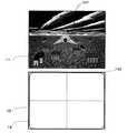
FIG. 1 is an external view of a
操作スイッチ部15は、LCD12の左横における下部ハウジング13bの一方主面に装着される方向指示スイッチ15a、スタートスイッチ15b、セレクトスイッチ15cと、LCD12の右横における下部ハウジング13bの一方主面に装着される動作スイッチ15d、15eを含む。方向指示スイッチ15aは、プレイヤによって操作可能なプレイヤオブジェクト(又はプレイヤキャラクタ)の移動方向を指示したり、カーソルの移動方向の指示等に用いられる。動作スイッチ15d、15eは、方向指示以外の動作、例えばアクションゲームにおいてはジャンプ、パンチ、武器を動かす等の指示、ロールプレイングゲーム(RPG)やシミュレーションRPGにおいてはアイテムの取得,武器又はコマンドの選択決定等の指示入力に使用される。また、必要に応じて、動作スイッチをさらに追加したり、下部ハウジング13bにおける操作スイッチ15の装着領域の上部面(上部側面)に側面スイッチ15L、15Rを設けてもよい。 The
LCD12の上面には、タッチパネル16が装着される。タッチパネル16は、例えば、抵抗膜方式、光学式(赤外線方式),静電容量結合式の何れの種類でもよく、その上面をスタイラスペン17(又は指でも可)で押圧操作又は移動操作若しくは撫でる操作をしたとき、スタイラスペン17の座標位置を検出して座標データを出力するものである。 A
上部ハウジング13aの側面近傍には、必要に応じてタッチパネル16を操作するスタイラスペン17を収納するための収納孔14bが形成される。この収納孔14bには、スタイラスペン17が収納される。下部ハウジング13bの側面の一部には、ゲームプログラムを記憶したメモリ(例えば、ROM)を内蔵したメモリカード18を着脱自在に装着するためのカートリッジ挿入部(図示せず)が形成される。カートリッジ挿入部の内部には、メモリカード18と電気的に接続するためのコネクタ(図示せず)が内蔵される。さらに、下部ハウジング13b(又は上部ハウジング13aでも可)には、CPU等の各種電子部品を実装した電子回路基板(後述の図2に示す30)が収納される。なお、ゲームプログラムを記憶する情報記憶媒体としては、ROM又はフラッシュメモリのような不揮発性半導体メモリに限らず、CD−ROMやDVD若しくはそれに類する光学式ディスク状記憶媒体でもよい。 A
図2は、携帯ゲーム装置10のブロック図である。図2において、ハウジング13に収納される電子回路基板30には、CPU31が実装される。CPU31には、バス32を介して、コネクタ33が接続されるととともに、入出力インターフェース(I/F)回路34、第1のグラフィック処理ユニット(第1GPU)35、第2のグラフィック処理ユニット(第2GPU)36、RAM37およびLCDコントローラ40が接続される。コネクタ33には、メモリカード18が着脱自在に接続される。メモリカード18は、ゲームプログラムを格納するための記憶媒体であり、具体的には、ゲームプログラムを記憶するROM180とバックアップデータを書き換え可能に記憶するRAM185とを搭載する。メモリカード18のROM180に記憶されたゲームプログラムはRAM37にロードされ、RAM37にロードされたゲームプログラムがCPU31によって実行される。CPU31がゲームプログラムを実行して得られる一時的なデータや画像を生成するためのデータがRAM37に記憶される。I/F回路34には、操作スイッチ部15及びタッチパネル16が接続されるとともに、スピーカ19が接続される。スピーカ19は、音抜き孔14aの内側位置に配置される。 FIG. 2 is a block diagram of the
第1GPU35には、第1のビデオRAM(以下「VRAM」)38が接続され、第2GPU36には、第2のビデオRAM(以下「VRAM」)39が接続される。第1GPU35は、CPU31からの指示に応じて、RAM37に記憶される画像を生成するためのデータに基づいて第1のゲーム画像を生成し、第1VRAM38に描画する。第2GPU36は、CPU31からの指示に応じて、RAM37に記憶される画像を生成するためのデータに基づいて第2のゲーム画像を生成し、第2VRAM39に描画する。第1VRAM38および第2VRAM39はLCDコントローラ40に接続される。 A first video RAM (hereinafter “VRAM”) 38 is connected to the
LCDコントローラ40はレジスタ41を含む。レジスタ41はCPU31からの指示に応じて0または1の値を記憶する。LCDコントローラ40は、レジスタ41の値が0の場合は、第1VRAM38に描画されたゲーム画像をLCD11に出力し、第2VRAM39に描画されたゲーム画像をLCD12に出力する。また、レジスタ41の値が1の場合は、第1VRAM38に描画されたゲーム画像をLCD12に出力し、第2VRAM39に描画されたゲーム画像をLCD11に出力する。 The
I/F回路34は、操作スイッチ部15、タッチパネル16、およびスピーカ19などの外部入出力装置とCPU31との間のデータの受け渡しを行う回路である。タッチパネル16(タッチパネル用のデバイスドライバを含む)は、スタイラスペン17によって入力(指示)された位置に対応する位置座標のデータを出力するものである。なお、本実施例では、表示画面の解像度は256dot×192dotであり、タッチパネル16の検出精度も表示画面に対応した256dot×192dotとして説明するが、タッチパネル16の検出精度は表示画面の解像度よりも低いものであってもよいし、高いものであってもよい。 The I /
次に、図3〜図7を用いて、本実施形態で想定するゲームの概要について説明する。図3は、本実施形態で想定するゲームの画面の一例である。本実施形態で想定するゲームは、3Dシューティングゲームである。図3において、LCD11には、プレイヤの操作対象となる飛行機101が表示されている。また、LCD12にもマップや操作レバーなどの画像を表示してもよい。そして、LCD12上に配設されたタッチパネル16の操作面である操作領域102の面上をスタイラスペン17でタッチまたは/およびドラッグ(スタイラスペン17をタッチパネル16上で滑らせる動作)することで飛行機101の操作が可能となる。具体的には、飛行機101の進行方向を左に向けたいときは、まず、操作領域102の中央領域をタッチし、そのタッチ位置からスタイラスペン17を左にドラッグするように動かす(第1の操作方法)。これによって、飛行機101の機首が左に向き、進行方向が左に変化する。また、この操作方法とは別に、例えば、上記操作領域102の中央領域外の左端領域をいきなりタッチするだけでも、飛行機101の進行方向を左に向けることもできる(第2の操作方法)。これは、例えば、プレイヤが、タッチパネル16の左端のほうを意図的に押した場合は、進行方向を左にすぐに曲げたいという意思があるものと考えられるからである。 Next, the outline of the game assumed in the present embodiment will be described with reference to FIGS. FIG. 3 is an example of a game screen assumed in this embodiment. The game assumed in this embodiment is a 3D shooting game. In FIG. 3, the
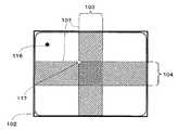
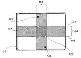
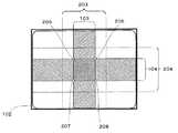
次に、上記操作についての処理概要を図4〜図7を用いて説明すると、まず、本実施形態では、図4に示すように、操作領域102をいくつかのエリアに分ける。言い換えれば、操作領域102に対応する座標系の座標領域をいくつかのエリアに定義されている。ここで定義されているとは、エリアを特定するためにプログラム中に記述されている座標範囲データを指す。この座標範囲データの記述に従って分岐処理(例えばステップS22,32など)が行われる。なお、このエリアの定義は、プログラム中に記述される場合の他、例えばテーブルデータとしてプログラムとは別に持たしたり、予めハードウェア側で定義しておいたりすることもできる。図4では、X軸方向に着目して分けたエリアであって、操作領域102の中央付近を含んだ領域であるXクランプエリア103がある。また、Y軸方向に着目して分けたエリアであって、操作領域102の中央付近を含んだ領域であるYクランプエリア104がある。そして、当該2つのクランプエリア以外のエリアである、クランプ外エリア106がある。このようにエリア分けした操作領域102において、例えば、上記の第1の操作方法で飛行機101の進行方向を左に向けるときは、次のような処理が行われる(ここで、説明の便宜上、タッチパネル16の操作領域102の座標系については、操作領域102の中央の座標を(0,0)とし、左方向および下方向をマイナス値で表すものとする)。まず、図4に示すように、プレイヤが操作領域102の中央付近(両クランプエリアが重複しているエリア内)の点111をタッチオン(タッチ入力の開始)すると、当該点111が原点(基準座標)に設定される。そして、プレイヤが操作領域102の端のほうの点112までスタイラスペン17をドラッグさせたとする。すると、上記原点である点111と、当該点112との座標の差分が、「X方向に−100、Y方向に0(以下、差分については、(−100,0)のように表記する)」のように算出される。そして、当該差分に基づいて、原点から入力座標への入力方向及び原点から入力座標までの距離を算出し、飛行機101の進行方向を大きく変化させる(X方向に−100の量だけ変化させる)。これにより、飛行機の進行方向を左に向けることができる。 Next, the processing outline of the operation will be described with reference to FIGS. 4 to 7. First, in the present embodiment, the
なお、図5に示すように、中央付近の点111をタッチオンした後、スタイラスペン17を点113までドラッグさせた場合は、上記原点である点111と、当該入力点113との座標の差分が、例えば、(−10,0)のように算出される。そして、当該差分に基づいて、飛行機101の進行方向がほんの少しだけ左方向に変化する(−10の量だけ変化する)ような制御が行われる。この場合は、変化量が少ないため、飛行機101の進行方向に大きな変化はなく、ほぼ真っ直ぐ飛び続けることになる。つまり、操作領域102の中央付近でスタイラスペン17を移動させているときは、飛行機101の進行方向に大きな変化は起きないが、中央から端のほうにスタイラスペン17を大きく移動させることで、進行方向を大きく変化させることができ、あたかもジョイスティックを用いたときのようなアナログの操作感覚を提供している。 As shown in FIG. 5, when the
次に、上記第2の操作方法で飛行機101の進行方向を左に向けるときの処理概要を説明する。この場合は、図6に示すように、プレイヤは、操作領域102に触れていない状態から、操作領域102の左端近傍にある点114をタッチオンする。当該点114は、上記Xクランプエリア103の外にある。このように、クランプエリア外の領域がタッチされたときは、X軸およびY軸それぞれについて、当該タッチオンした点から最寄りの境界107上の点を原点とする。図6の場合は、X軸方向については、Xクランプエリア103の外であるため、最寄りの境界107上の座標が原点のX座標として設定されるが、Y軸方向については、Yクランプエリア104の内であるため、タッチオンした点114のY座標がそのまま原点のY座標として用いられる。その結果、当該タッチオンした点から最寄りの境界107上の点115が原点として設定されることになる。そして、当該タッチした点114と原点に設定された点115との差分を求める。その結果、タッチオンしたと同時に、差分として、例えば(−150、0)という値が算出され、当該差分に基づいて飛行機101の進行方向を左に大きく変化させることが可能となる。同様に、プレイヤが、図7に示すように操作領域102の左上端近傍の点116をタッチしたときは、原点としては、X方向、Y方向それぞれの最寄りの境界107上の点117が原点として設定される。その結果、差分として、例えば(−150、150)と算出され、飛行機101の進行方向が左上方向に大きく変化する。 Next, an outline of processing when the traveling direction of the
このように、操作領域102の端のほうをタッチオンするだけで、あたかもジョイスティックを急に傾けたかのように、飛行機101の進行方向を大きく変化させることができる。また、Xクランプエリア内をタッチして操作した場合は、タッチ入力し始めた点(タッチオン時の点)がそのまま原点のX座標として処理され、Yクランプエリア内をタッチして操作した場合は、タッチ入力し始めた点がそのまま原点のY座標として処理される。そのため、中央付近(両クランプエリアが重複しているエリア内)であまりスタイラスペン17を動かさないようなタッチ操作をし続けているときは、飛行機101の細かい動作制御が可能となる。 In this way, by simply touching on the end of the
次に、ゲーム装置10において実行されるゲーム処理の詳細を図8〜図18を用いて説明する。図8は、ゲーム装置10において実行されるゲーム処理の流れを示すフローチャートである。ゲーム装置10の電源が投入されると、ゲーム装置10のCPU31は、図示しないブートROMに記憶されている起動プログラムを実行し、RAM37等の各ユニットが初期化される。そして、メモリカード18に格納されたゲームプログラムがRAM37に読み込まれ、当該ゲームプログラムの実行が開始される。その結果、第1LCD11および第2LCD12にゲーム画像などが表示される(図3参照)。また、このとき、上述したような操作領域102のエリア分けの定義、すなわち、上記Xクランプエリア103等の領域が定義されている。図8におけるフローチャートは、プレイヤの操作対象オブジェクトである飛行機101を移動させる操作を行うときにおけるゲーム処理を示す。なお、本実施形態においては、飛行機101の操作以外の状況におけるゲーム処理は本発明と直接関連しないので説明を省略する。また、図8に示すステップS1〜ステップS10の処理は、1フレーム毎に繰り返し実行される。 Next, details of the game process executed in the
図8において、まず、タッチパネル16の操作領域102にタッチ入力があると、タッチパネル16(タッチパネルを制御するデバイスドライバ等を含む)からその位置に対応する位置座標のデータが出力される。CPU31は、タッチパネル16からこの出力データを検出することにより、プレイヤが操作領域102にタッチしているか否かを判断する(ステップS1)。ステップS1の判定の結果、プレイヤがタッチパネル16に触れていない場合は(ステップS1でNO)、プレイヤ等によりタッチパネル16が触れられている(タッチ状態)か否か(非タッチ状態)を示すためのフラグである接触フラグをオフにする(ステップS8)。更に、原点座標と入力座標の差分を(0,0)にして(ステップS9)、処理を次のステップS10に進める。一方、プレイヤがタッチパネル16に触れている場合は(ステップS1でYES)、処理を次のステップS2に進める。
なお、本実施例では、タッチパネル16から出力される位置座標の値を直接利用して処理を行う例を示すが、例えば操作領域102の中心を原点とした−1〜1の範囲で上記位置座標を正規化してこの正規化後の値を利用するようにしてもよい。In FIG. 8, first, when a touch input is made in the
In the present embodiment, an example is shown in which processing is performed by directly using the value of the position coordinate output from the
次に、CPU21は、プレイヤのタッチパネル16に対するタッチ操作がタッチ開始時か否かを判断する(ステップS2)。すなわち、非タッチ状態からタッチ状態に変化したか否かを判定する。より具体的には、接触フラグがオンかオフかを判定する。そして、接触フラグがオンであれば、タッチ操作が継続している状態であるため(ステップS2でYES)、処理をステップS6に進める。一方、接触フラグがオフであれば、タッチ入力の開始時であるため(ステップS2でNO)、接触フラグをオンに設定する(ステップS3)。その後、処理をステップS4のタッチオンX軸処理に進める。 Next, the
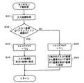
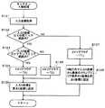
図9は、上記ステップS4で示したタッチオンX軸処理の詳細を示すフローチャートである。図9において、まず、CPU31は、タッチパネル16から出力された位置座標(以下、入力座標)を取得する(ステップS21)。次に、CPU31は、取得した入力座標のX座標(以下、入力X座標と呼ぶ)が、Xクランプエリア103の範囲内に位置しているか否かを判定する(ステップS22)。その結果、当該エリアの範囲内に位置していれば(ステップS22でYES)、直前に入力された入力X座標がX軸上においてどのエリアにあったかを示すためのフラグであるXエリアフラグに「2」を設定する(ステップS23)。そして、入力X座標を原点座標のX座標(以下、原点X座標)として設定する(ステップS24)。 FIG. 9 is a flowchart showing details of the touch-on X-axis process shown in step S4. In FIG. 9, first, the
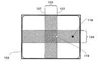
一方、ステップS22の判定の結果、Xクランプエリア103の範囲外であれば(ステップS22でNO)、CPU31は、Xエリアフラグに「1」を設定する(ステップS25)。続けて、入力座標からX方向に最寄の位置にある、Xクランプエリア103とクランプ外エリア106との境界107のX座標を原点X座標として設定する(ステップS26)。例えば、上述した図6を例に取ると、タッチした場所が点114の場合は、原点X座標としては、点115のX座標が設定される。また、図10に示すように、入力した点が右側寄りの点118の場合は、最寄りの境界である、右側の境界107上の点119のX座標(つまり、右側の境界107のX座標そのもの)が原点X座標に設定される。以上で、タッチオンX軸処理は終了する。 On the other hand, if the result of determination in step S22 is that it is outside the range of the X clamp area 103 (NO in step S22), the
図8に戻り、タッチオンX軸処理が終わると、続いてタッチオンY軸処理が行われる(ステップS5)。図11は、上記ステップS5で示したタッチオンY軸処理の詳細を示すフローチャートである。図11において、まず、CPU21は、タッチパネル16から出力された入力座標を取得する(ステップS31)。次に、CPU31は、取得した入力座標のY座標(以下、入力Y座標と呼ぶ)が、Yクランプエリア104の範囲内に位置しているか否かを判定する(ステップS32)。その結果、当該エリアの範囲内に位置していれば(ステップS32でYES)、直前に入力された入力Y座標がY軸上においてどのエリアにあったかを示すためのフラグであるYエリアフラグに「2」を設定する(ステップS33)。そして、入力Y座標を原点座標のY座標(以下、原点Y座標)に設定する(ステップS34)。 Returning to FIG. 8, when the touch-on X-axis process is completed, the touch-on Y-axis process is subsequently performed (step S5). FIG. 11 is a flowchart showing details of the touch-on Y-axis process shown in step S5. In FIG. 11, first, the
一方、ステップS32の判定の結果、Yクランプエリア104の範囲外であれば(ステップS32でNO)、CPU31は、Yエリアフラグに「1」を設定する(ステップS35)。続けて、入力座標からY方向に最寄の境界107のY座標を原点Y座標として設定する(ステップS36)。例えば、図12に示すように、タッチした場所が点120の場合は、点121のY座標が原点Y座標として設定される。また、タッチした場所が点122の場合は、点123のY座標が原点Y座標に設定される。以上で、タッチオンY軸処理は終了する。 On the other hand, if the result of determination in step S32 is outside the range of the Y clamp area 104 (NO in step S32), the
図8に戻り、次に、上記ステップS2の判定の結果、タッチ状態が継続中(ステップS2でYES)のときの処理について説明する。タッチ状態が継続中の場合は、まず、X軸方向処理が行われる(ステップS6)。 Returning to FIG. 8, the process when the touch state is continuing (YES in step S2) as a result of the determination in step S2 will be described. If the touch state is continuing, first, X-axis direction processing is performed (step S6).
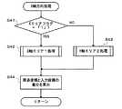
図13は、上記ステップS6で示したX軸方向処理の詳細を示すフローチャートである。図13においては、CPU31は、まず、Xエリアフラグが「1」であるか否かを判定する(ステップS41)。その結果、Xエリアフラグが「1」であれば(ステップS41でYES)、処理がX軸エリア1処理(ステップS42)に進められる。一方、Xエリアフラグが「1」でなければ(ステップS41でNO)、処理がX軸エリア2処理(ステップS43)に進められる。 FIG. 13 is a flowchart showing details of the X-axis direction processing shown in step S6. In FIG. 13, the
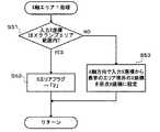
図14は、上記ステップS42で示したX軸エリア1処理の詳細を示すフローチャートである。図14において、CPU31は、まず、入力X座標の位置がXクランプエリア103の範囲内であるかを判定する(ステップS51)。その結果、Xクランプエリア103の範囲内であれば(ステップS51でYES)、Xエリアフラグを「2」に設定する(ステップS52)。これは、Xクランプエリア103の外からエリア内に入ったことになるためである。一方、エリア外であれば(ステップS51でNO)、上記図6で示したように、X方向に最寄の境界107のX座標を原点X座標として設定する(ステップS53)。以上で、X軸エリア1処理は終了する。 FIG. 14 is a flowchart showing details of the
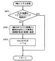
図15は、上記ステップS43で示したX軸エリア2処理の詳細を示すフローチャートである。図15において、CPU31は、まず、入力X座標の位置がXクランプエリア103の範囲内にあるかを判定する(ステップS61)。その結果、Xクランプエリア103内にあれば(ステップS61でYES)、そのまま処理を終了する。つまり、Xクランプエリア103内がタッチされている間は、原点X座標の位置には変更を加えない。一方、当該エリアの範囲外であれば(ステップS61でNO)、上記図6で示したように、入力座標からX方向に最寄の境界107のX座標を原点X座標として設定する(ステップS62)。更に、Xエリアフラグを「1」に設定する(ステップS63)。以上で、X軸エリア2処理は終了する。 FIG. 15 is a flowchart showing details of the
図13に戻り、上記ステップS42あるいはS43の処理の次に、CPU31は、X座標についての差分、すなわち、原点X座標と入力X座標との差分を算出する(ステップS44)。以上でX軸方向処理が終了する。 Returning to FIG. 13, after the process of step S42 or S43, the
図8に戻り、ステップS6のX軸方向処理が終われば、続いてY軸方向処理が行われる(ステップS7)。図16は、上記ステップS7で示したY軸方向処理の詳細を示すフローチャートである。図16において、CPU31は、まず、Yエリアフラグが「1」であるか否かを判定する(ステップS71)。その結果、Yエリアフラグが「1」であれば(ステップS71でYES)、処理がY軸エリア1処理(ステップS72)に進められる。一方、Yエリアフラグが「1」でなければ(ステップS71でNO)、処理がY軸エリア2処理(ステップS73)に進められる。 Returning to FIG. 8, when the X-axis direction process in step S6 is completed, the Y-axis direction process is subsequently performed (step S7). FIG. 16 is a flowchart showing details of the Y-axis direction processing shown in step S7. In FIG. 16, the
図17は、上記ステップS72で示したY軸エリア1処理の詳細を示すフローチャートである。図17において、CPU31は、まず、入力Y座標の位置がYクランプエリア104の範囲内であるかを判定する(ステップS81)。その結果、Yクランプエリア104の範囲内であれば(ステップS81でYES)、CPU31は、Yエリアフラグを「2」に設定する(ステップS82)。一方、当該エリアの範囲外であれば(ステップS81でNO)、上記図12を用いて示したように、入力座標からY方向に最寄の境界107のY座標を原点Y座標として設定する(ステップS83)。以上で、Y軸エリア1処理が終了する。 FIG. 17 is a flowchart showing details of the Y-
図18は、上記ステップS73で示したY軸エリア2処理の詳細を示すフローチャートである。図18において、まず、CPU31は、Yクランプエリア104の範囲内に入力Y座標が位置しているかを判定する(ステップS91)。その結果、Yクランプエリア104の範囲内にあれば(ステップS91でYES)、そのまま処理を終了する。一方、当該エリアの範囲外にあれば(ステップS91でNO)、上記図12で示したように、入力座標からY方向に最寄の境界107のY座標を原点Y座標として設定する(ステップS92)。更に、Yエリアフラグを「1」に設定する(ステップS93)。以上で、Y軸エリア2処理が終了する。 FIG. 18 is a flowchart showing details of the Y-
図16に戻り、上記ステップS72あるいはS73の処理の次に、CPU31は、原点座標と入力座標とのY座標についての差分を算出する(ステップS74)。以上でY軸方向処理が終了する。 Returning to FIG. 16, after the process of step S72 or S73, the
図8に戻り、上記ステップS5のタッチオンY軸処理、ステップS7のY軸方向処理あるいはステップS9の処理の次に、CPU31は、算出されたX座標及びY座標の差分に基づいて、プレイヤの操作対象となっているオブジェクトの動作を制御する処理を行う(ステップS10)。例えば、CPU31は、入力座標と原点との差分から、それらの距離L1を求める。具体的には、上記操作領域102の座標系において、入力座標を(tx、ty)、原点を(ox、oy)とすると、CPU21は、差分vxおよびvyを、
vx=ox−tx
vy=oy−ty
として求める。そして、CPU21は、距離L1を、
vx = ox-tx
vy = oy-ty
Asking. Then, the
このように、第1の実施形態では、クランプエリア内がタッチされているときは、その座標を原点座標とし、クランプエリア外がタッチされたときは、原点を最寄りの境界上の座標に設定している。これにより、タッチパネル16の端のほうをタッチするだけで、例えば急ハンドルを切るような、移動量の大きな操作を簡単に行うことができる。また、原点を、中央ではなく、入力座標から最寄りの境界上に設定することにより、例えば一旦左に切ったハンドルを右に切り返すような操作を行うとき等におけるスタイラスペン17の移動量を少なくすることができ、操作のレスポンスを高めて操作性をよくすることができる。また、タッチパネル16の中央付近については、入力座標をそのまま原点として設定する。そのため、タッチパネル16の中心を原点として固定するのに比べ、例えば手ぶれ等で、入力座標が原点から少しずれただけで進行方向がずれるような、過敏な反応による操作性の悪化を防ぐことができる。その結果、人間の操作感覚に合致し、過敏すぎず鈍すぎない、適度なレスポンスを持った、操作性の良いゲームを提供することができる。 Thus, in the first embodiment, when the inside of the clamp area is touched, the coordinates are set as the origin coordinates, and when the outside of the clamp area is touched, the origin is set to the coordinates on the nearest boundary. ing. Thereby, simply touching the end of the
なお、上述の実施形態では、クランプエリア外における原点の移動先として、クランプエリアの境界上の座標を用いていたが、境界上に限らず、入力座標とクランプエリアの境界との間(入力座標とクランプエリアの境界とを結ぶ線分上)であれば、どの位置に移動させてもよい。例えば、上記図7を例にとれば、境界107上にある点117の位置は、もう少し左上であってもよい。 In the above-described embodiment, the coordinates on the boundary of the clamp area are used as the movement destination of the origin outside the clamp area. However, the coordinates are not limited to the boundary, but between the input coordinates and the boundary of the clamp area (input coordinates). As long as it is on a line segment connecting the boundary of the clamp area and the clamp area). For example, taking FIG. 7 as an example, the position of the
また、タッチオン時に原点が設定された後は、タッチオフされるまでの間、当該原点の位置を変化させないようにしても良い。 Further, after the origin is set at the time of touch-on, the position of the origin may not be changed until the touch is turned off.
また、ゲームの展開具合に応じて、クランプエリアの大きさを変化させるようにしてもよい。これにより、ゲーム展開に応じてタッチパネル16の操作性を変化させることができ、よりバラエティに富んだ内容のゲームを提供できる。 Further, the size of the clamp area may be changed according to the game development. Thereby, the operativity of the
(第2の実施形態)
次に、図19から図30を参照して、本発明の第2の実施形態について説明する。上述の第1の実施形態では、クランプエリア外の領域がタッチオンされたときは、原点をクランプエリアの境界上のいずれかの位置に設定していた。これに対して、第2の実施形態では、クランプエリアの外側に、更に中間エリアを設ける。そして、当該中間エリア内においてタッチオンされた時は、その入力座標を原点として設定するが、時間の経過とともに、クランプエリアの境界上の座標へと当該原点を移動させる処理が行われる。(Second Embodiment)
Next, a second embodiment of the present invention will be described with reference to FIGS. In the first embodiment described above, when an area outside the clamp area is touched on, the origin is set at any position on the boundary of the clamp area. On the other hand, in the second embodiment, an intermediate area is further provided outside the clamp area. When the touch-on is performed in the intermediate area, the input coordinates are set as the origin, but as the time passes, the origin is moved to coordinates on the boundary of the clamp area.
図19は、第2の実施形態におけるタッチパネル16の操作面である操作領域102のエリア定義の例を示した図である。図19においては、Xクランプエリア103よりも広いX中間エリア203と、Yクランプエリア104よりも広いY中間エリア204とが予め定義されている。このようにエリア分けした操作領域102において、プレイヤがタッチオンした座標がこれら両中間エリア203、204内であって、両クランプエリア103、104内ではないときは、当該タッチオン時の入力座標を原点として一旦設定する。そして、時間の経過とともに、上述したようなクランプエリアの境界上の座標、すなわち、図19のクランプエリアと中間エリアの境界上の最寄りの点へと当該原点を移動させていく処理を行う。これは、人間のバランス感覚に照らすと、例えば、最初はプレイヤが操作領域102の中央から左寄りの点を意図的にタッチオンしたとしても、その後、タッチ操作を続けていると、プレイヤは、無意識のうちに操作領域102の中央付近を基準として指を動かす。つまり、原点の位置が操作領域102の中心付近にあるほうが、より人間の操作のバランス感覚に合致することから、時間の経過とともに原点を操作領域102の中心のほうに移動させるものである。そのため、タッチオンした箇所が操作領域102の中心でも端のほうでもないときには、徐々に原点を中心付近に移動させる処理を行うことで、操作領域102の操作をプレイヤのバランス感覚・操作感覚に一致させ、操作性をより高めるものである。(なお、操作領域102の端のほうをタッチオンしたときは、上述したように意図的な操作であると考えられるため、原点の移動は行わない。また、原点を中心まで移動させてしまうと、上述したような、原点から少しずれた入力をしただけで、プレイヤの操作対象である飛行機101等の進行方向がブレてしまうという問題が発生するため、中心付近でも端のほうでもない中間エリアにおいて、このような処理が行われる。) FIG. 19 is a diagram illustrating an example of area definition of the
なお、当該実施形態に係るゲーム装置10の構成は、図1および図2を用いて上述した第1の実施形態と同様であるため、同一の参照符号を付して詳細な説明を省略する。 Note that the configuration of the
以下、図20〜図30を用いて、本発明の第2の実施形態にかかるゲーム処理の詳細を説明する。図20は、第2の実施形態にかかるゲーム処理を示すフローチャートである。図20に示すフローは、第1の実施形態で図8を用いて説明したフローにおけるステップS4〜S7の処理が、ステップS104〜S107の処理に置き換わったものである。従って、ステップS104〜S107以外の処理については、詳細な説明を省略する。 Hereinafter, the details of the game processing according to the second embodiment of the present invention will be described with reference to FIGS. FIG. 20 is a flowchart showing a game process according to the second embodiment. The flow shown in FIG. 20 is obtained by replacing the processing in steps S4 to S7 in the flow described with reference to FIG. 8 in the first embodiment with the processing in steps S104 to S107. Therefore, detailed descriptions of processes other than steps S104 to S107 are omitted.
図21は、上記ステップS104で示した第2の実施形態におけるタッチオンX軸処理の詳細を示すフローチャートである。図21において、まず、CPU31は、タッチパネル16から出力された入力X座標を取得する(ステップS121)。次に、取得した入力X座標が、X中間エリア203の範囲内に位置しているか否かを判定する(ステップS122)。その結果、当該エリアの範囲内に位置していれば(ステップS122でYES)、当該入力X座標がXクランプエリア103の範囲内にあるか否かを判定する(ステップS123)。当該判定の結果、Xクランプエリア103の範囲内であれば(ステップS123でYES)、Xエリアフラグに「3」を設定する(ステップS124)。一方、Xクランプエリア103の範囲内でないときは(ステップS123でNO)、Xエリアフラグに「2」を設定する(ステップS125)。ステップS124またはS125の処理が終われば、CPU31は、入力X座標を原点X座標として設定する(ステップS126)。 FIG. 21 is a flowchart showing details of the touch-on X-axis process in the second embodiment shown in step S104. In FIG. 21, first, the
一方、ステップS122の判定の結果、入力X座標がX中間エリア203の範囲外であれば(ステップS122でNO)、Xエリアフラグに「1」を設定する(ステップS127)。続けて、入力X座標からX方向に最寄の位置にある、Xクランプエリア103とX中間エリア203との境界のX座標を原点X座標として設定する(ステップS128)。以上で、第2の実施形態におけるタッチオンX軸処理は終了する。 On the other hand, if the input X coordinate is outside the range of the X
図20に戻り、タッチオンX軸処理が終わると、続いてタッチオンY軸処理が行われる(ステップS105)。図22は、上記ステップS105で示したタッチオンY軸処理の詳細を示すフローチャートである。図22において、まず、CPU21は、タッチパネル16から出力された入力座標から入力Y座標を取得する(ステップS131)。次に、取得した入力Y座標が、Y中間エリア204の範囲内に位置しているか否かを判定する(ステップS132)。その結果、当該エリアの範囲内に位置していれば(ステップS132でYES)、当該入力Y座標の位置がYクランプエリア104の範囲内にあるか否かを判定する(ステップS133)。当該判定の結果、Yクランプエリア104の範囲内にあれば(ステップS133でYES)、Yエリアフラグに「3」を設定する(ステップS134)。一方、Yクランプエリア104の範囲内にないときは(ステップS133でNO)、Yエリアフラグに「2」を設定する(ステップS135)。そして、入力Y座標を原点Y座標に設定する(ステップS136)。 Returning to FIG. 20, when the touch-on X-axis process is completed, the touch-on Y-axis process is subsequently performed (step S105). FIG. 22 is a flowchart showing details of the touch-on Y-axis process shown in step S105. In FIG. 22, first, the
一方、ステップS132の判定の結果、入力Y座標の位置がY中間エリア204の範囲外であれば(ステップS132でNO)、Yエリアフラグに「1」を設定する(ステップS137)。続けて、入力座標から最寄のYクランプエリア104とY中間エリア204との境界のY座標を原点Y座標として設定する(ステップS138)。以上で、タッチオンY軸処理は終了する。これにより、タッチオンしたときのエリアがクランプエリア内、あるいは中間エリア内であるときは、その入力座標が原点座標として設定され、中間エリアの範囲外であるときは、クランプエリアと中間エリアの境界上の最寄りの点が原点として設定されることになる。 On the other hand, if the result of determination in step S132 is that the position of the input Y coordinate is outside the range of the Y intermediate area 204 (NO in step S132), “1” is set in the Y area flag (step S137). Subsequently, the Y coordinate of the boundary between the nearest
次に、図20のステップS2の判定の結果、タッチ状態が継続中(ステップS2でYES)のときの処理、すなわち、ステップS106およびS107の処理について説明する。タッチ状態が継続中の場合は、まず、X軸方向処理が行われる(ステップS106)。 Next, the process when the touch state is continuing (YES in step S2) as a result of the determination in step S2 in FIG. 20, that is, the processes in steps S106 and S107 will be described. When the touch state is continuing, X-axis direction processing is first performed (step S106).
図23は、上記ステップS106で示したX軸方向処理の詳細を示すフローチャートである。図23においては、まず、Xエリアフラグが「1」であるか否かが判定される(ステップS141)。その結果、Xエリアフラグが「1」であれば(ステップS141でYES)、処理がX軸エリア1処理(ステップS142)に進められる。一方、Xエリアフラグが「1」でなければ(ステップS141でNO)、Xエリアフラグが「2」であるか否かが判定される(ステップS143)。当該判定の結果、Xエリアフラグが「2」であれば(ステップ143でYES)、処理がX軸エリア2処理(ステップS144)に進められる。一方、「2」でなければ(ステップ143でNO)、処理がX軸エリア3処理(ステップS145)に進められる。 FIG. 23 is a flowchart showing details of the X-axis direction processing shown in step S106. In FIG. 23, first, it is determined whether or not the X area flag is “1” (step S141). As a result, if the X area flag is “1” (YES in step S141), the process proceeds to the
図24は、上記ステップS142で示したX軸エリア1処理の詳細を示すフローチャートである。図24において、まず、CPU31は、入力X座標の位置がX中間エリア203の範囲内であるかを判定する(ステップS151)。その結果、X中間エリア203の範囲内であれば(ステップS151でYES)、Xエリアフラグを「2」に設定する(ステップS152)。一方、エリア外であれば(ステップS151でNO)、中間エリアとクランプエリアの境界のうちX軸方向に最寄りの境界のX座標を原点X座標として設定する(ステップS153)。以上で、X軸エリア1処理は終了する。 FIG. 24 is a flowchart showing details of the
図25は、上記ステップS144で示したX軸エリア2処理の詳細を示すフローチャートである。図25において、まず、CPU31は、入力X座標の位置がX中間エリア203内であるかを判定する(ステップS161)。その結果、X中間エリア203内であれば(ステップS161でYES)、次に、入力X座標の位置がXクランプエリア103内であるかを判定する(ステップS162)。判定の結果、クランプエリア内であれば(ステップS162でYES)、原点X座標の位置がXクランプエリア103の範囲内にあるか否かを判定する(ステップS163)。当該判定の結果、原点X座標がXクランプエリア103内にないときは(ステップS163でNO)、最寄りのXクランプエリア103の境界のX座標を原点X座標に設定する(ステップS164)。一方、原点X座標がXクランプエリア103内にあるときは(ステップS163でYES)、そのまま処理をステップS165に進める。つまり、Xクランプエリア103内がタッチされている間は、原点X座標には変更を加えない。そして、Xエリアフラグに「3」を設定する(ステップS165)。 FIG. 25 is a flowchart showing details of the
一方、上記ステップS162で入力X座標の位置が、X中間エリア203内ではあるがXクランプエリア103外と判定されたときは(ステップS162でNO)、原点X座標の位置がXクランプエリア103の範囲内にあるか否かを判定する(ステップS166)。当該判定の結果、原点X座標がXクランプエリア103内にないときは(ステップS166でNO)、原点X座標の値を、最寄りのXクランプエリア103の境界のX座標に所定の値だけ近づける(ステップS167)。例えば、当該所定の値を1とすれば、1フレーム毎に原点のX座標が上記最寄りの境界のX座標に近づいていく。この結果、X中間エリア203内では、原点座標のX座標がXクランプエリア103の境界上のX座標へ時間の経過とともに移動していくことになる。もちろん、1フレーム毎移動させることに限らず、例えば30フレーム毎に1だけ近づけるようにしてもよいし、タッチオン時からの経過時間を計測しておき、当該経過時間に応じて移動させるようにしてもよい。なお、境界上の座標まで移動すれば、それ以上の移動は行われない。一方、ステップS166の判定の結果、原点X座標がXクランプエリア103内にあるときは(ステップS166でYES)、そのまま処理を終了する。 On the other hand, if it is determined in step S162 that the input X coordinate position is within the X
一方、ステップS161の判定の結果、入力X座標がX中間エリア203の外にあれば(ステップS161でNO)、入力X座標から最寄の境界上のX座標を原点X座標として設定する(ステップS168)。更に、Xエリアフラグを「1」に設定する(ステップS169)。以上で、X軸エリア2処理は終了する。 On the other hand, as a result of the determination in step S161, if the input X coordinate is outside the X intermediate area 203 (NO in step S161), the X coordinate on the nearest boundary from the input X coordinate is set as the origin X coordinate (step S161). S168). Further, the X area flag is set to “1” (step S169). Thus, the
図26は、上記ステップS145で示したX軸エリア3処理の詳細を示すフローチャートである。図26において、まず、CPU21は、入力X座標が、Xクランプエリア103内にあるか否かを判定する(ステップS171)。当該判定の結果、Xクランプエリア103内にあれば(ステップS171でNO)、そのまま処理を終了する。一方、Xクランプエリア103の外にあれば(ステップS171でYES)、Xエリアフラグを「2」に設定する(ステップS172)。以上で、X軸エリア3処理は終了する。 FIG. 26 is a flowchart showing details of the X-axis area 3 process shown in step S145. In FIG. 26, first, the
図23に戻り、上記ステップS142、S144、またはS145の処理が終われば、X座標についての、原点座標と入力座標との差分を算出する(ステップS146)。以上でX軸方向処理が終了する。 Returning to FIG. 23, when the process of step S142, S144, or S145 is completed, the difference between the origin coordinate and the input coordinate with respect to the X coordinate is calculated (step S146). The X-axis direction processing is thus completed.
図20に戻り、ステップS106のX軸方向処理が終われば、続いてY軸方向処理が行われる(ステップS107)。図27は、上記ステップS107で示したY軸方向処理の詳細を示すフローチャートである。図27においては、CPU31は、まず、Yエリアフラグが「1」であるか否かを判定する(ステップS181)。その結果、Yエリアフラグが「1」であれば(ステップS181でYES)、処理がY軸エリア1処理(ステップS182)に進められる。一方、Yエリアフラグが「1」でなければ(ステップS181でNO)、Yエリアフラグが「2」であるか否かが判定される(ステップS183)。当該判定の結果、Yエリアフラグが「2」であれば(ステップS183でYES)、処理がY軸エリア2処理(ステップS184)に進められる。一方、「2」でなければ、処理がY軸エリア3処理(ステップS185)に進められる。 Returning to FIG. 20, when the X-axis direction process in step S106 is completed, the Y-axis direction process is subsequently performed (step S107). FIG. 27 is a flowchart showing details of the Y-axis direction processing shown in step S107. In FIG. 27, the
図28は、上記ステップS182で示したY軸エリア1処理の詳細を示すフローチャートである。図28において、まず、入力Y座標がY中間エリア204の範囲内にあるかを判定する(ステップS191)。その結果、Y中間エリア204の範囲内であれば(ステップS191でYES)、Yエリアフラグを「2」に設定する(ステップS192)。一方、当該エリア外であれば(ステップS191でNO)、Y中間エリア204とYクランプエリア104の境界のうち最寄りの境界のY座標を原点Y座標として設定する(ステップS193)。以上で、Y軸エリア1処理は終了する。 FIG. 28 is a flowchart showing details of the Y-
図29は、上記ステップS184で示したY軸エリア2処理の詳細を示すフローチャートである。図29において、まず、入力Y座標の位置がY中間エリア204内であるかを判定する(ステップS201)。その結果、Y中間エリア204内であれば(ステップS201でYES)、次に、入力Y座標の位置がYクランプエリア104内であるかを判定する(ステップS202)。判定の結果、Yクランプエリア104内であれば(ステップS202でYES)、原点Y座標の位置がYクランプエリア104内にあるか否かを判定する(ステップS203)。当該判定の結果、原点Y座標がYクランプエリア104内にないときは(ステップS203でNO)、Y方向に最寄りのYクランプエリア104の境界のY座標を原点Y座標に設定する(ステップS204)。一方、原点Y座標がYクランプエリア104内にあるときは(ステップS203でYES)、そのまま処理を次に進める。つまり、原点Y座標に変更を加えない。そして、Yエリアフラグに「3」を設定する(ステップS205)。 FIG. 29 is a flowchart showing details of the Y-
一方、上記ステップS202で入力Y座標がY中間エリア204内ではあるがYクランプエリア104外と判定されたときは(ステップS202でNO)、原点Y座標がYクランプエリア104内であるか否かを判定する(ステップS206)。当該判定の結果、原点Y座標がYクランプエリア104内でないときは(ステップS206でNO)、上述したステップS167の処理と同様に、原点Y座標を、最寄りの境界のY座標に所定の値だけ近づける(ステップS207)。この結果、Y中間エリア204内では、時間の経過とともに、原点Y座標が境界のY座標に移動することになる。また、境界の座標まで移動すれば、それ以上の移動は行われない。一方、原点Y座標がYクランプエリア104内であるときは(ステップS206でYES)、そのまま処理を終了する。 On the other hand, when it is determined in step S202 that the input Y coordinate is within the Y
一方、ステップS201の判定の結果、入力Y座標がYクランプエリア104外であれば(ステップS201でNO)、入力Y座標から最寄の境界上のY座標を原点Y座標として設定する(ステップS208)。更に、Yエリアフラグを「1」に設定する(ステップS209)。以上で、第2の実施形態におけるY軸エリア2処理は終了する。 On the other hand, if the result of determination in step S201 is that the input Y coordinate is outside the Y clamp area 104 (NO in step S201), the Y coordinate on the nearest boundary from the input Y coordinate is set as the origin Y coordinate (step S208). ). Further, the Y area flag is set to “1” (step S209). Above, the Y-
図30は、図27のステップS185で示したY軸エリア3処理の詳細を示すフローチャートである。図30において、まず、CPU31は、入力Y座標が、Yクランプエリア104の範囲内にあるか否かを判定する(ステップS211)。当該判定の結果、Yクランプエリア104内にあれば(ステップS211でNO)、そのまま処理を終了する。一方、Yクランプエリア104内になければ(ステップS211でYES)、Yエリアフラグを「2」に設定する。以上で、Y軸エリア3処理は終了する。 FIG. 30 is a flowchart showing details of the Y-axis area 3 process shown in step S185 of FIG. In FIG. 30, first, the
このように、第2の実施形態では、中間エリア内でタッチオンされたときは、その入力座標を原点に設定するが、時間の経過とともに原点の位置を徐々にタッチパネルの中心方向に移動させる。このように、原点の位置を中心近傍に移動させることで、人間の操作感覚(バランス感覚)に合致させることができ、より操作性の高いゲームを提供することが可能となる。 Thus, in the second embodiment, when touch-on is performed in the intermediate area, the input coordinates are set as the origin, but the position of the origin is gradually moved toward the center of the touch panel as time passes. As described above, by moving the position of the origin to the vicinity of the center, it is possible to match a human operation feeling (balance feeling), and it is possible to provide a game with higher operability.
(第3の実施形態)
次に、本発明の第3の実施形態について説明する。上述の第2の実施形態では、上記中間エリア内においてタッチオンされた時は、その入力座標を原点として設定し、時間の経過とともに、クランプエリアの境界上の座標へと当該原点を移動させていた。これに対して、第3の実施形態では、中間エリア内がタッチされている間は、原点は固定したままにする。そして、中間エリアの外側がタッチされたとき、原点を最寄りのクランプエリアの境界上に移動させる。(Third embodiment)
Next, a third embodiment of the present invention will be described. In the second embodiment described above, when touch-on is performed in the intermediate area, the input coordinate is set as the origin, and the origin is moved to the coordinates on the boundary of the clamp area as time passes. . On the other hand, in the third embodiment, the origin is kept fixed while the inside of the intermediate area is touched. When the outside of the intermediate area is touched, the origin is moved to the boundary of the nearest clamp area.
なお、当該実施形態に係るゲーム装置10の構成は、図1および図2を用いて上述した第1の実施形態と同様であるため、同一の参照符号を付して詳細な説明を省略する。 Note that the configuration of the
次に、本発明の第3の実施形態にかかるゲーム処理の詳細を説明する。第3の実施形態にかかるゲーム処理は、図20〜図30を用いて説明した上記第2の実施形態にかかるゲーム処理と基本的には同様である。ただし、図25で説明したX軸エリア処理2のフローチャートが、図31で示すフローチャートに置き換わる。また、図29で説明したY軸エリア処理2のフローチャートが、図32で示すフローチャートに置き換わる。従って、図31および図32以外の処理については、詳細な説明を省略する。 Next, the details of the game processing according to the third embodiment of the present invention will be described. The game process according to the third embodiment is basically the same as the game process according to the second embodiment described with reference to FIGS. However, the flowchart of the
図31に示すフローチャートは、図25のX軸エリア2の処理から、ステップS163、S164、S166、S167の処理を抜いたものである。また、図32に示すフローチャートは、図29のY軸エリア2の処理から、ステップS203、S204、S206、S207の処理を抜いたものである。つまり、第3の実施形態では、入力X座標が中間エリア内にあるときは、原点X座標の位置を変化させない。そして、入力X座標が中間エリアの外に出たときに、中間エリアとクランプエリアの境界のうちX軸方向に最寄りの境界のX座標を原点X座標として設定する。これと同様の処理が、Y座標についても行われる。このような処理を行うことで、第3の実施形態における入力座標と原点との関係は、図33に示すようになる。図33は、第3の実施形態における入力座標と原点との関係を説明するための図である。図33においては、第2の実施形態と同様に中間エリア203、204が予め定義されている。そして、例えば図33(a)に示す点301をプレイヤが指でタッチオンすると、点302が原点に設定される。この状態で、タッチしたまま右方向に水平に指をずらしていった場合を考える。この場合、指が図33(b)に示すように中間エリア内にある点303まで移動しても、原点の位置は変化しない。その後、図3(c)に示す点305のように中間エリアの外まで指が移動したら、原点の位置が点306に設定されることになる。 The flowchart shown in FIG. 31 is obtained by removing the processing of steps S163, S164, S166, and S167 from the processing of the
このように、第3の実施形態では、中間エリア内をタッチしているときは原点の位置を固定し、中間エリア外をタッチしているときは、最寄りのクランプエリアの境界に原点を移動させている。これにより、中間エリアの大きさの設定次第で、クランプエリアの範囲内に留まらずに、原点が固定される範囲のみを調節することができる。その結果、ゲームの種類や内容に応じてより細やかに操作性を調整することができる。 As described above, in the third embodiment, the position of the origin is fixed when the inside of the intermediate area is touched, and the origin is moved to the boundary of the nearest clamp area when the outside of the intermediate area is touched. ing. Thus, depending on the setting of the size of the intermediate area, it is possible to adjust only the range where the origin is fixed, without staying within the clamp area. As a result, the operability can be adjusted more finely according to the type and content of the game.
本実施例では、2つの表示装置を備えた携帯型ゲーム装置を例に説明したが、単一の表示装置を備え当該表示装置の画面上にタッチパネルを備えた携帯端末であってもよい。また、本実施例では、操作領域に対するプレイヤの指示位置を検出する装置としてタッチパネルを例に上げたが、プレイヤが所定領域内の位置を指示できるいわゆるポインティングデバイスであればよく、例えば、画面上の任意位置を指示可能なマウス、表示画面を持たない操作面上の任意位置を指示するタブレット、遠隔から表示画面や表示画面周囲に配置されたマーカ等を撮像するための撮像手段を備えたデバイスによって、表示画面方向を指し示すことにより得られる撮像画像における表示画面やマーカの位置から、表示画面上の指し示された位置に相当する表示画面上の座標を算出するポインティングデバイスなどでもよい。 In the present embodiment, the portable game device including two display devices has been described as an example. However, a portable terminal including a single display device and a touch panel on the screen of the display device may be used. In the present embodiment, the touch panel is taken as an example of a device for detecting the player's designated position with respect to the operation area. However, a so-called pointing device that allows the player to designate a position in the predetermined area may be used. By a device equipped with an imaging means for imaging a mouse that can indicate an arbitrary position, a tablet that indicates an arbitrary position on the operation surface that does not have a display screen, and a marker that is remotely arranged around the display screen or display screen A pointing device that calculates coordinates on the display screen corresponding to the indicated position on the display screen from the position of the display screen or marker in the captured image obtained by pointing the display screen direction may be used.
本発明にかかるオブジェクト処理装置およびオブジェクト処理プログラムは、操作領域に対するプレイヤの指示位置に対応する指示座標に基づいて仮想空間内のオブジェクトに対する処理を実行するオブジェクト処理装置の操作性を高めることができ、携帯型ゲーム装置や据え置き型ゲーム装置等の用途に有用である。 The object processing device and the object processing program according to the present invention can improve the operability of the object processing device that executes processing for an object in the virtual space based on the designated coordinates corresponding to the designated position of the player with respect to the operation area. This is useful for applications such as portable game devices and stationary game devices.
10 携帯ゲーム装置
11 第1LCD
12 第2LCD
13 ハウジング
14a 音抜き孔
14b 収納孔
15 操作スイッチ部
16 タッチパネル
17 スタイラスペン
18 メモリカード
19 スピーカ
30 電子回路基板
31 CPU
32 バス
33 コネクタ
34 インターフェース回路
35 第1GPU
36 第2GPU
37 RAM
38 第1VRAM
39 第2VRAM
40 LCDコントローラ
41 レジスタ
51 ブロック
180 ROM
185 RAM
10
12 Second LCD
13 Housing 14a
32
36 Second GPU
37 RAM
38 First VRAM
39 Second VRAM
40
185 RAM
Claims (22)
Translated fromJapanese前記操作領域は、前記操作領域の中央近傍の領域を含む第1の領域と当該第1の領域を囲むように配置されている第2の領域との少なくとも2種類に分けて定義されており、
前記指示座標を検出する指示座標検出部と、
前記指示座標が前記第1の領域又は前記第2の領域に含まれるかを判別する指示座標判別部と、
前記指示座標が前記第1の領域内に含まれると判別されたとき、当該指示座標を基準座標として設定し、当該指示座標が前記第2の領域内に含まれると判別されたとき、当該指示座標よりも第1の領域側の所定座標を基準座標として設定する基準座標設定部と、
前記基準座標と前記指示座標との位置関係に基づいて、前記仮想空間における前記オブジェクトの動作制御を行う動作制御部とを備える、オブジェクト処理装置。An object processing device that executes processing on an object in a virtual space based on designated coordinates corresponding to a designated position of a player with respect to an operation area,
The operation area is defined by being divided into at least two types of a firstarea including an area near the center of the operation area and a second areaarranged so as to surround the first area.
An instruction coordinate detection unit for detecting the instruction coordinates;
An indicated coordinate determination unit for determining whether the indicated coordinates are included in the first area or the second area;
When it is determined that the indicated coordinate is included in the first area, the indicated coordinate is set as a reference coordinate, and when it is determined that the indicated coordinate is included in the second area, the instruction A reference coordinate setting unit that sets predetermined coordinates closer to the first region than the coordinates as reference coordinates;
An object processing apparatus comprising: a motion control unit that performs motion control of the object in the virtual space based on a positional relationship between the reference coordinates and the designated coordinates.
前記指示座標判別部は、前記基準座標設定部によって基準座標が設定された後かつ前記指示座標検出部によって時間の経過に伴い連続して指示座標が検出されているとき、当該指示座標が前記第3の領域を外れたか否かをさらに判別し、
前記基準座標設定部は、前記第3の領域を外れていないと判別される場合には基準座標の位置を変化させず、前記第3の領域を外れたと判別される場合には当該指示座標よりも第1の領域側の所定座標を基準座標として設定する、請求項8に記載のオブジェクト処理装置。In the operation area, a third area including the first area is defined,
The indicated coordinate determination unit is configured such that when the reference coordinate is set by the reference coordinate setting unit and the indicated coordinate is continuously detected as time passes by the indicated coordinate detection unit, the indicated coordinate is Further determine whether or not the area of 3
The reference coordinate setting unit does not change the position of the reference coordinate when it is determined that the third area is not deviated, and from the designated coordinate when it is determined that the third area is deviated. The object processing apparatus according to claim8 , wherein predetermined coordinates on the first area side are set as reference coordinates.
前記基準座標設定部は、前記指示座標が前記第4の領域内に含まれると判別されたとき、当該指示座標を基準座標として設定し、その後、前記指示座標検出部によって連続して指示座標が検出されている間は、当該基準座標の位置が前記操作領域の中央に徐々に近づいていくように、当該基準座標の位置を変更する、請求項1に記載のオブジェクト処理装置。In the second region, a fourth region is further defined on the first region side,
When it is determined that the designated coordinate is included in the fourth area, the reference coordinate setting unit sets the designated coordinate as a reference coordinate, and then the designated coordinate is continuously detected by the designated coordinate detection unit. The object processing apparatus according to claim 1, wherein the position of the reference coordinate is changed so that the position of the reference coordinate gradually approaches the center of the operation area while being detected .
前記操作領域は、前記操作領域の中央近傍の領域を含む第1の領域と当該第1の領域を囲むように配置されている第2の領域との少なくとも2種類に分けて定義されており、
前記指示座標を検出する指示座標検出ステップと、
前記指示座標が前記第1の領域又は前記第2の領域に含まれるかを判別する指示座標判別ステップと、
前記指示座標が前記第1の領域内に含まれると判別されたとき、当該指示座標を基準座標として設定し、当該指示座標が前記第2の領域内に含まれると判別されたとき、当該指示座標よりも第1の領域側の所定座標を基準座標として設定する基準座標設定ステップと、
前記基準座標と前記指示座標との位置関係に基づいて、前記仮想空間における前記オブジェクトの動作制御を行う動作制御ステップとを前記コンピュータに実行させる、オブジェクト処理プログラム。An object processing program that is executed by a computer of an object processing device that executes processing on an object in a virtual space based on designated coordinates corresponding to a designated position of a player with respect to an operation area,
The operation area is defined by being divided into at least two types of a firstarea including an area near the center of the operation area and a second areaarranged so as to surround the first area.
A designated coordinate detecting step for detecting the designated coordinates;
An instruction coordinate determination step of determining whether the instruction coordinates are included in the first area or the second area;
When it is determined that the indicated coordinate is included in the first area, the indicated coordinate is set as a reference coordinate, and when it is determined that the indicated coordinate is included in the second area, the instruction A reference coordinate setting step for setting predetermined coordinates closer to the first region than the coordinates as reference coordinates;
An object processing program that causes the computer to execute an operation control step for performing an operation control of the object in the virtual space based on a positional relationship between the reference coordinates and the designated coordinates.
前記指示座標判別ステップは、前記基準座標設定ステップによって基準座標が設定された後かつ前記指示座標検出ステップによって時間の経過に伴い連続して指示座標が検出されているとき、当該指示座標が前記第3の領域を外れたか否かをさらに判別し、
前記基準座標設定ステップは、前記第3の領域を外れていないと判別される場合には基準座標の位置を変化させず、前記第3の領域を外れたと判別される場合には当該指示座標よりも第1の領域側の所定座標を基準座標として設定する、請求項18に記載のオブジェクト処理プログラム。In the operation area, a third area including the first area is defined,
In the indicated coordinate determination step, when the reference coordinate is set in the reference coordinate setting step and the indicated coordinate is detected continuously as time passes by the indicated coordinate detection step, the indicated coordinate is Further determine whether or not the area of 3
In the reference coordinate setting step, the position of the reference coordinate is not changed when it is determined that the third area is not deviated, and from the designated coordinate when it is determined that the third area is deviated. The object processing program according to claim18 , wherein predetermined coordinates on the first area side are set as reference coordinates.
前記基準座標設定ステップにおいて、前記指示座標が前記第4の領域内に含まれると判別されたとき、当該指示座標を基準座標として設定し、その後、前記指示座標検出ステップにおいて連続して指示座標が検出されている間は、当該基準座標の位置が前記操作領域の中央に徐々に近づいていくように、当該基準座標の位置を変更する、請求項11に記載のオブジェクト処理プログラム。In the second region, a fourth region is further defined on the first region side,
In the reference coordinate setting step, when it is determined that the designated coordinate is included in the fourth area, the designated coordinate is set as a reference coordinate, and then the designated coordinate is continuously detected in the designated coordinate detection step. The object processing program according to claim11, wherein the position of the reference coordinate is changed so that the position of the reference coordinate gradually approaches the center of the operation area while being detected .
前記操作領域は、前記操作領域の中央近傍の領域を含む第1の領域と当該第1の領域を囲むように配置されている第2の領域との少なくとも2種類に分けて定義されており、The operation area is defined by being divided into at least two types of a first area including an area near the center of the operation area and a second area arranged so as to surround the first area.
前記指示座標を検出する指示座標検出部と、An instruction coordinate detection unit for detecting the instruction coordinates;
前記指示座標が前記第1の領域又は前記第2の領域に含まれるかを判別する指示座標判別部と、An indicated coordinate determination unit for determining whether the indicated coordinates are included in the first area or the second area;
前記指示座標が前記第1の領域内に含まれると判別されたとき、当該指示座標を基準座標として設定し、当該指示座標が前記第2の領域内に含まれると判別されたとき、当該指示座標よりも第1の領域側の所定座標を基準座標として設定する基準座標設定部と、When it is determined that the indicated coordinate is included in the first area, the indicated coordinate is set as a reference coordinate, and when it is determined that the indicated coordinate is included in the second area, the instruction A reference coordinate setting unit that sets predetermined coordinates closer to the first region than the coordinates as reference coordinates;
前記基準座標と前記指示座標との位置関係に基づいて、前記仮想空間における前記オブジェクトの動作制御を行う動作制御部とを備える、オブジェクト処理システム。An object processing system comprising: a motion control unit that performs motion control of the object in the virtual space based on a positional relationship between the reference coordinates and the designated coordinates.
前記操作領域は、前記操作領域の中央近傍の領域を含む第1の領域と当該第1の領域を囲むように配置されている第2の領域との少なくとも2種類に分けて定義されており、The operation area is defined by being divided into at least two types of a first area including an area near the center of the operation area and a second area arranged so as to surround the first area.
前記コンピュータに、前記指示座標を検出させる指示座標検出ステップと、An instruction coordinate detection step for causing the computer to detect the instruction coordinates;
前記コンピュータに、前記指示座標が前記第1の領域又は前記第2の領域に含まれるかを判別させる指示座標判別ステップと、An instruction coordinate determination step for causing the computer to determine whether the instruction coordinates are included in the first area or the second area;
前記コンピュータに、前記指示座標判別ステップにおいて、前記指示座標が前記第1の領域内に含まれると判別されたときは、当該指示座標を基準座標として設定させ、当該指示座標が前記第2の領域内に含まれると判別されたときは、当該指示座標よりも第1の領域側の所定座標を基準座標として設定させる基準座標設定ステップと、When the instruction coordinate determination step determines that the instruction coordinate is included in the first area, the computer is caused to set the instruction coordinate as a reference coordinate, and the instruction coordinate is the second area. A reference coordinate setting step for setting, as a reference coordinate, a predetermined coordinate on the first region side from the indicated coordinate;
前記コンピュータに、前記基準座標と前記指示座標との位置関係に基づいて、前記仮想空間における前記オブジェクトの動作制御を行わせる動作制御ステップとを備える、オブジェクト処理方法。An object processing method comprising: an operation control step for causing the computer to perform operation control of the object in the virtual space based on a positional relationship between the reference coordinates and the designated coordinates.
Priority Applications (3)
| Application Number | Priority Date | Filing Date | Title |
|---|---|---|---|
| JP2006129368AJP5041730B2 (en) | 2006-05-08 | 2006-05-08 | Object processing apparatus and object processing program |
| US11/592,248US8643640B2 (en) | 2006-05-08 | 2006-11-03 | Object processing apparatus and storage medium having object processing program stored thereon |
| EP06024291.4AEP1854519B1 (en) | 2006-05-08 | 2006-11-23 | Object processing apparatus and storage medium having object processing program stored thereon |
Applications Claiming Priority (1)
| Application Number | Priority Date | Filing Date | Title |
|---|---|---|---|
| JP2006129368AJP5041730B2 (en) | 2006-05-08 | 2006-05-08 | Object processing apparatus and object processing program |
Publications (2)
| Publication Number | Publication Date |
|---|---|
| JP2007300961A JP2007300961A (en) | 2007-11-22 |
| JP5041730B2true JP5041730B2 (en) | 2012-10-03 |
Family
ID=37670288
Family Applications (1)
| Application Number | Title | Priority Date | Filing Date |
|---|---|---|---|
| JP2006129368AActiveJP5041730B2 (en) | 2006-05-08 | 2006-05-08 | Object processing apparatus and object processing program |
Country Status (3)
| Country | Link |
|---|---|
| US (1) | US8643640B2 (en) |
| EP (1) | EP1854519B1 (en) |
| JP (1) | JP5041730B2 (en) |
Families Citing this family (8)
| Publication number | Priority date | Publication date | Assignee | Title |
|---|---|---|---|---|
| JP5294612B2 (en)* | 2007-11-15 | 2013-09-18 | インターナショナル・ビジネス・マシーンズ・コーポレーション | Method, apparatus and program for automatically generating reference marks in a virtual shared space |
| JP5374170B2 (en)* | 2009-01-22 | 2013-12-25 | 任天堂株式会社 | Information processing program, information processing apparatus, information processing system, and information processing method |
| JP5436909B2 (en)* | 2009-03-30 | 2014-03-05 | 任天堂株式会社 | Information processing program, information processing apparatus, information processing system, and information processing method |
| JP5717270B2 (en)* | 2009-12-28 | 2015-05-13 | 任天堂株式会社 | Information processing program, information processing apparatus, and information processing method |
| KR101154636B1 (en) | 2010-02-03 | 2012-06-08 | 닌텐도가부시키가이샤 | Display device, game system, and game method |
| JP6523509B1 (en)* | 2018-03-30 | 2019-06-05 | 株式会社コロプラ | Game program, method, and information processing apparatus |
| JP6683352B2 (en)* | 2018-10-05 | 2020-04-15 | 株式会社コナミデジタルエンタテインメント | Program and information processing device |
| JP7604327B2 (en)* | 2021-06-08 | 2024-12-23 | 株式会社コロプラ | Game Program |
Family Cites Families (16)
| Publication number | Priority date | Publication date | Assignee | Title |
|---|---|---|---|---|
| US4698460A (en)* | 1986-08-26 | 1987-10-06 | Tektronix, Inc. | Touch panel system |
| JP3289072B2 (en) | 1993-12-22 | 2002-06-04 | 株式会社セガ | Vector input device |
| JPH08112448A (en)* | 1994-10-17 | 1996-05-07 | Konbi Kk | controller |
| JPH0969037A (en) | 1995-08-31 | 1997-03-11 | Sharp Corp | Data processing device |
| JP3212914B2 (en) | 1997-07-30 | 2001-09-25 | 群馬日本電気株式会社 | Input device |
| JPH11154074A (en) | 1997-11-25 | 1999-06-08 | Sharp Corp | Scroll control device |
| JPH11175212A (en)* | 1997-12-15 | 1999-07-02 | Hitachi Ltd | Touch operation processing method for touch panel device |
| US6203432B1 (en)* | 1999-05-11 | 2001-03-20 | Madcatz, Inc. | System for adjusting the response characteristic of an electronic game input device |
| US7071919B2 (en) | 2001-02-26 | 2006-07-04 | Microsoft Corporation | Positional scrolling |
| WO2003065190A2 (en)* | 2002-01-29 | 2003-08-07 | Meta4Hand Inc. | Computer pointer control |
| KR20070011391A (en)* | 2004-04-23 | 2007-01-24 | 서크 코퍼레이션 | Improved methods for scrolling and edge motion on the touchpad |
| JP3734819B1 (en) | 2004-07-26 | 2006-01-11 | 任天堂株式会社 | GAME PROGRAM, GAME DEVICE, AND INPUT DEVICE |
| JP4471761B2 (en) | 2004-07-26 | 2010-06-02 | 任天堂株式会社 | GAME PROGRAM, GAME DEVICE, AND INPUT DEVICE |
| JP3734820B1 (en) | 2004-09-03 | 2006-01-11 | 任天堂株式会社 | GAME PROGRAM, GAME DEVICE, AND INPUT DEVICE |
| JP4658544B2 (en)* | 2004-09-03 | 2011-03-23 | 任天堂株式会社 | GAME PROGRAM, GAME DEVICE, AND INPUT DEVICE |
| JP2006122241A (en) | 2004-10-27 | 2006-05-18 | Nintendo Co Ltd | Game device and game program |
- 2006
- 2006-05-08JPJP2006129368Apatent/JP5041730B2/enactiveActive
- 2006-11-03USUS11/592,248patent/US8643640B2/enactiveActive
- 2006-11-23EPEP06024291.4Apatent/EP1854519B1/enactiveActive
Also Published As
| Publication number | Publication date |
|---|---|
| EP1854519A1 (en) | 2007-11-14 |
| JP2007300961A (en) | 2007-11-22 |
| US8643640B2 (en) | 2014-02-04 |
| EP1854519B1 (en) | 2018-07-18 |
| US20070257907A1 (en) | 2007-11-08 |
Similar Documents
| Publication | Publication Date | Title |
|---|---|---|
| JP5041730B2 (en) | Object processing apparatus and object processing program | |
| JP3734819B1 (en) | GAME PROGRAM, GAME DEVICE, AND INPUT DEVICE | |
| JP5711409B1 (en) | Terminal device | |
| US9229562B2 (en) | Information processing apparatus and storage medium for storing information processing program | |
| JP3734820B1 (en) | GAME PROGRAM, GAME DEVICE, AND INPUT DEVICE | |
| JP5808712B2 (en) | Video display device | |
| JP4405430B2 (en) | GAME PROGRAM AND GAME DEVICE | |
| JP5133515B2 (en) | GAME DEVICE AND GAME PROGRAM | |
| JP4471761B2 (en) | GAME PROGRAM, GAME DEVICE, AND INPUT DEVICE | |
| JP5379275B2 (en) | GAME DEVICE AND GAME PROGRAM | |
| JP4388878B2 (en) | Input processing program and input processing apparatus | |
| JP2007130312A (en) | Game program and game apparatus | |
| JP4658544B2 (en) | GAME PROGRAM, GAME DEVICE, AND INPUT DEVICE | |
| JP4121492B2 (en) | GAME DEVICE AND GAME PROGRAM | |
| JP6189515B1 (en) | GAME METHOD AND GAME PROGRAM | |
| JP7475800B2 (en) | Directional input program, direction input device, and program using direction input | |
| JP5354820B2 (en) | Input processing program and input processing apparatus | |
| JP4724740B2 (en) | Input processing program and input processing apparatus | |
| JP4302767B2 (en) | Input processing program and input processing apparatus | |
| JP2009116908A (en) | Input processing program and input processing apparatus | |
| JP5363524B2 (en) | Input processing program and input processing apparatus | |
| JP2018041354A (en) | Pointer control system and pointer control program |
Legal Events
| Date | Code | Title | Description |
|---|---|---|---|
| A621 | Written request for application examination | Free format text:JAPANESE INTERMEDIATE CODE: A621 Effective date:20090414 | |
| RD02 | Notification of acceptance of power of attorney | Free format text:JAPANESE INTERMEDIATE CODE: A7422 Effective date:20110902 | |
| A131 | Notification of reasons for refusal | Free format text:JAPANESE INTERMEDIATE CODE: A131 Effective date:20111222 | |
| A521 | Request for written amendment filed | Free format text:JAPANESE INTERMEDIATE CODE: A523 Effective date:20120214 | |
| TRDD | Decision of grant or rejection written | ||
| A01 | Written decision to grant a patent or to grant a registration (utility model) | Free format text:JAPANESE INTERMEDIATE CODE: A01 Effective date:20120709 | |
| A01 | Written decision to grant a patent or to grant a registration (utility model) | Free format text:JAPANESE INTERMEDIATE CODE: A01 | |
| A61 | First payment of annual fees (during grant procedure) | Free format text:JAPANESE INTERMEDIATE CODE: A61 Effective date:20120710 | |
| R150 | Certificate of patent or registration of utility model | Free format text:JAPANESE INTERMEDIATE CODE: R150 Ref document number:5041730 Country of ref document:JP Free format text:JAPANESE INTERMEDIATE CODE: R150 | |
| FPAY | Renewal fee payment (event date is renewal date of database) | Free format text:PAYMENT UNTIL: 20150720 Year of fee payment:3 | |
| R250 | Receipt of annual fees | Free format text:JAPANESE INTERMEDIATE CODE: R250 | |
| R250 | Receipt of annual fees | Free format text:JAPANESE INTERMEDIATE CODE: R250 | |
| R250 | Receipt of annual fees | Free format text:JAPANESE INTERMEDIATE CODE: R250 | |
| R250 | Receipt of annual fees | Free format text:JAPANESE INTERMEDIATE CODE: R250 | |
| R250 | Receipt of annual fees | Free format text:JAPANESE INTERMEDIATE CODE: R250 | |
| R250 | Receipt of annual fees | Free format text:JAPANESE INTERMEDIATE CODE: R250 | |
| R250 | Receipt of annual fees | Free format text:JAPANESE INTERMEDIATE CODE: R250 | |
| R250 | Receipt of annual fees | Free format text:JAPANESE INTERMEDIATE CODE: R250 | |
| R250 | Receipt of annual fees | Free format text:JAPANESE INTERMEDIATE CODE: R250 | |
| R250 | Receipt of annual fees | Free format text:JAPANESE INTERMEDIATE CODE: R250 |