JP5040760B2 - Image processing apparatus, imaging apparatus, display control method, and program - Google Patents
Image processing apparatus, imaging apparatus, display control method, and programDownload PDFInfo
- Publication number
- JP5040760B2 JP5040760B2JP2008075096AJP2008075096AJP5040760B2JP 5040760 B2JP5040760 B2JP 5040760B2JP 2008075096 AJP2008075096 AJP 2008075096AJP 2008075096 AJP2008075096 AJP 2008075096AJP 5040760 B2JP5040760 B2JP 5040760B2
- Authority
- JP
- Japan
- Prior art keywords
- image
- difference value
- assist
- size
- captured image
- Prior art date
- Legal status (The legal status is an assumption and is not a legal conclusion. Google has not performed a legal analysis and makes no representation as to the accuracy of the status listed.)
- Expired - Fee Related
Links
Images


Classifications
- G—PHYSICS
- G06—COMPUTING OR CALCULATING; COUNTING
- G06V—IMAGE OR VIDEO RECOGNITION OR UNDERSTANDING
- G06V40/00—Recognition of biometric, human-related or animal-related patterns in image or video data
- G06V40/10—Human or animal bodies, e.g. vehicle occupants or pedestrians; Body parts, e.g. hands
- G06V40/16—Human faces, e.g. facial parts, sketches or expressions
- G06V40/161—Detection; Localisation; Normalisation
- G06V40/166—Detection; Localisation; Normalisation using acquisition arrangements
- H—ELECTRICITY
- H04—ELECTRIC COMMUNICATION TECHNIQUE
- H04N—PICTORIAL COMMUNICATION, e.g. TELEVISION
- H04N23/00—Cameras or camera modules comprising electronic image sensors; Control thereof
- H04N23/60—Control of cameras or camera modules
- H04N23/61—Control of cameras or camera modules based on recognised objects
- H04N23/611—Control of cameras or camera modules based on recognised objects where the recognised objects include parts of the human body
- H—ELECTRICITY
- H04—ELECTRIC COMMUNICATION TECHNIQUE
- H04N—PICTORIAL COMMUNICATION, e.g. TELEVISION
- H04N23/00—Cameras or camera modules comprising electronic image sensors; Control thereof
- H04N23/60—Control of cameras or camera modules
- H04N23/63—Control of cameras or camera modules by using electronic viewfinders
- H04N23/633—Control of cameras or camera modules by using electronic viewfinders for displaying additional information relating to control or operation of the camera
- H04N23/635—Region indicators; Field of view indicators
- H—ELECTRICITY
- H04—ELECTRIC COMMUNICATION TECHNIQUE
- H04N—PICTORIAL COMMUNICATION, e.g. TELEVISION
- H04N23/00—Cameras or camera modules comprising electronic image sensors; Control thereof
- H04N23/60—Control of cameras or camera modules
- H04N23/64—Computer-aided capture of images, e.g. transfer from script file into camera, check of taken image quality, advice or proposal for image composition or decision on when to take image
Landscapes
- Engineering & Computer Science (AREA)
- Multimedia (AREA)
- Signal Processing (AREA)
- Health & Medical Sciences (AREA)
- General Health & Medical Sciences (AREA)
- Oral & Maxillofacial Surgery (AREA)
- Human Computer Interaction (AREA)
- Physics & Mathematics (AREA)
- General Physics & Mathematics (AREA)
- Theoretical Computer Science (AREA)
- Studio Devices (AREA)
Description
Translated fromJapanese本発明は、画像処理装置に関し、特に、撮像画像を表示させる画像処理装置、撮像装置および表示制御方法ならびに当該方法をコンピュータに実行させるプログラムに関する。The present invention relates to animage processing apparatus , and more particularlyto an image processing apparatus that displays a captured image, an imaging apparatus, adisplay control method, and a program that causes a computer to execute the method.
従来、人物等の被写体を撮像して撮像画像を記録するデジタルスチルカメラやデジタルビデオカメラ等の撮像装置が普及している。また、近年では、人物の顔を検出し、この検出された顔に基づいて各種撮像パラメータを設定する撮像装置が存在する。さらに、検出された顔が特定人物の顔であるか否かを識別し、この識別された特定人物を撮影者に通知する撮像装置が提案されている。これらの撮像装置を用いて撮影を行うことにより、撮像装置の扱いに不慣れな者であっても、所望の人物を含む撮像画像を比較的綺麗に記録することができる。 2. Description of the Related Art Conventionally, imaging apparatuses such as digital still cameras and digital video cameras that capture an image of a subject such as a person and record a captured image have become widespread. In recent years, there are imaging apparatuses that detect a human face and set various imaging parameters based on the detected face. Further, there has been proposed an imaging apparatus that identifies whether or not the detected face is a face of a specific person and notifies the photographer of the identified specific person. By photographing using these imaging devices, even a person unfamiliar with the handling of the imaging device can record a captured image including a desired person relatively beautifully.
ここで、例えば、旅行先の観光地で有名な建物を背景にした人物をデジタルスチルカメラで撮影する場合には、その有名な建物と人物との構図が重要となる。このため、撮像範囲内での建物と人物との位置およびサイズを考慮して撮影することが重要となるが、撮像装置の扱いに不慣れな者にとっては、これらの位置およびサイズを考慮した撮影が困難であることが考えられる。 Here, for example, when a person with a background of a famous building in a tourist destination is photographed with a digital still camera, the composition of the famous building and the person is important. For this reason, it is important to take a picture in consideration of the position and size of the building and the person in the imaging range. It can be difficult.
そこで、例えば、撮像すべき被写体のフレーム内の位置およびサイズを表す目標構図データを取得し、撮像画像から検出された被写体の位置およびサイズとその目標構図データが表す被写体の位置およびサイズとを比較することにより、これらの差異を算出し、これらの差異が減少するように、ズーム倍率、撮像する向き等を案内する撮像装置が提案されている(例えば、特許文献1参照。)。
上述の従来技術によれば、静止画を撮影する場合に、撮像装置の扱いに不慣れな者であっても、適切な構図により撮像画像を記録することができる。 According to the above-described conventional technology, even when a person who is unfamiliar with the handling of the imaging apparatus can shoot a still image, the captured image can be recorded with an appropriate composition.
ここで、例えば、旅行先の観光地で特定人物をデジタルビデオカメラにより撮影する場合について考える。この場合についても、撮像範囲内での観光地の背景と特定人物との位置およびサイズを考慮して撮影することが重要である。しかしながら、上述の従来技術に示す構図(例えば、特定人物の全身)により撮像画像を記録する場合には、似たような構図の動画が連続して記録されることになる。このため、このように記録された撮像動画を視聴する場合には、似たような構図の動画が連続して再生されるため、再生時間の経過に応じて、再生中の動画に対する視聴者の興味が低減してしまうおそれがある。 Here, for example, consider a case where a specific person is photographed with a digital video camera at a tourist destination. Also in this case, it is important to take a picture in consideration of the position and size of the background of the tourist spot and the specific person within the imaging range. However, when a captured image is recorded according to the composition shown in the above-described prior art (for example, the whole body of a specific person), a moving image having a similar composition is continuously recorded. For this reason, when viewing a captured moving image recorded in this way, a moving image having a similar composition is continuously played back. Therefore, as the playback time passes, Interest may be reduced.
そこで、本発明は、視聴する際に視聴者の興味をひく画像を容易に記録することを目的とする。Accordingly, an object of the present invention is to easily record animage that attracts the viewer's interest when viewing.
本発明は、上記課題を解決するためになされたものであり、その第1の側面は、撮像画像から所定の対象物を検出する対象物検出手段による検出情報を取得する検出情報取得手段と、上記撮像画像において上記対象物を配置すべき配置状態を示す配置アシスト画像を上記撮像画像に重ねて表示手段に表示させ、上記表示されている配置アシスト画像により特定される対象物の位置と上記検出された対象物の上記撮像画像における位置との差分値である位置差分値と、上記表示されている配置アシスト画像により特定される対象物のサイズと上記検出された対象物の上記撮像画像におけるサイズとの差分値であるサイズ差分値との双方が所定の範囲内になった場合には、上記撮像画像における上記配置アシスト画像を別の配置アシスト画像に変化させる表示制御手段とを具備する画像処理装置およびその表示制御方法ならびに当該方法をコンピュータに実行させるプログラムである。これにより、配置アシスト画像を撮像画像に重ねて表示させ、位置差分値およびサイズ差分値の双方が所定の範囲内になった場合には、撮像画像における配置アシスト画像を別の配置アシスト画像に変化させるという作用をもたらす。
また、この第1の側面において、上記表示制御手段は、上記位置差分値および上記サイズ差分値の双方が所定の範囲内になった場合には、上記表示されている配置アシスト画像を別の配置アシスト画像に変更することにより、上記撮像画像における上記配置アシスト画像の位置およびサイズを変化させるようにしてもよい。これにより、位置差分値およびサイズ差分値の双方が所定の範囲内になった場合には、表示されている配置アシスト画像を別の配置アシスト画像に変更することにより、撮像画像における配置アシスト画像の位置およびサイズを変化させるという作用をもたらす。The present invention has been made to solve the above-described problems, and a first aspect of the present invention isa detection information acquisition unit that acquires detection information by a target detection unit that detects a predetermined target from a captured image; the layout assistantimage in the captured image showing the arrangement should be placed above the object to be displayed on thedisplay means superimposed onthe captured image, the position andthe detection of the object identified by the layout assistant image which isthe display a position difference value which is a difference value between the position inthe captured image of the object that is, the size ofthe captured image of the size andthe detected object of the object identified by the layout assistant image which isthe display when both of the size difference value which is a difference value between becomes within a predetermined range, varyingthe layout assistant imagein the captured imageto another layout assistant imageThe image processing apparatus and adisplay control method, and the method thereof and a display control means fora program for executing a computer.Thereby, displayed over theplacement assistant image to the captured image, when both of the position difference value and size difference value is within a predetermined range,the layout assistant image to another layout assistant image in the captured image It brings about the effect ofchanging .
In the first aspect, the display control means may arrange the displayed arrangement assist image in a different arrangement when both the position difference value and the size difference value are within a predetermined range. You may make it change the position and size of the said arrangement | positioning assist image in the said captured image by changing to an assist image. As a result, when both the position difference value and the size difference value are within a predetermined range, the displayed arrangement assist image is changed to another arrangement assist image, so that the arrangement assist image of the captured image is changed. The effect is to change the position and size.
また、この第1の側面において、上記表示制御手段は、上記位置差分値および上記サイズ差分値の双方が所定の範囲内になる度に、所定の順序に従って上記表示されている配置アシスト画像を別の配置アシスト画像に変更することにより上記撮像画像における上記配置アシスト画像の位置およびサイズを順次変化させるようにしてもよい。これにより、位置差分値およびサイズ差分値の双方が所定の範囲内になった場合には、複数の配置アシスト画像を所定の順序に従って順次表示させるという作用をもたらす。Further, in the first aspect,the display control means, every time both ofthe position difference value andsaid size difference value falls within a predeterminedrange,the layout assistant image which is the display in the order ofJo Tokoro You may make itchange sequentiallythe position and size of the said arrangement assistance image in the said captured image by changing to another arrangement assistance image . As a result, when both the position difference value and the size difference value are within a predetermined range, there is an effect of sequentially displaying a plurality of arrangement assist images in a predetermined order.
また、この第1の側面において、上記検出された対象物が特定の対象物であるか否かを識別する特定対象物識別手段をさらに具備し、上記表示制御手段は、上記表示されている配置アシスト画像および上記識別された特定の対象物に関する上記位置差分値および上記サイズ差分値の双方が所定の範囲内になった場合に上記撮像画像における上記配置アシスト画像を別の配置アシスト画像に変化させるようにしてもよい。これにより、識別された特定の対象物に関する位置差分値およびサイズ差分値の双方が所定の範囲内になった場合に、撮像画像における配置アシスト画像を別の配置アシスト画像に変化させるという作用をもたらす。The arrangement in the first embodiment,the detected object is further comprising a specific object identifying means for identifying whether a particular object,said display control means, which isthe displaythe layout assistant imagein the captured image is changedto another layout assistant image when both ofthe position difference value andsaid size difference value relating to the assistant image andthe identified specific object become within predetermined ranges You may do it. Thereby, when both the position difference value and the size difference value relating to the identified specific object are within a predetermined range,the arrangement assist image in the captured image is changed to another arrangement assist image. .
また、この第1の側面において、上記識別された特定の対象物の上記撮像画像における位置およびサイズに基づいて上記識別された特定の対象物に付す特定対象物マーカを生成する特定対象物マーカ生成手段をさらに具備し、上記表示制御手段は、上記配置アシスト画像と上記生成された特定対象物マーカとを上記撮像画像に重ねて表示させるようにしてもよい。これにより、特定の対象物に付す特定対象物マーカを生成し、配置アシスト画像と、生成された特定対象物マーカとを撮像画像に重ねて表示させるという作用をもたらす。Also, in the first aspect, product specific object marker to generate a specific object marker to be subjected tothe identified specific object based on the position and size ofthe captured image ofthe identified specific object further comprising means,said display controlmeans, and a specific object marker that isthe layout assistant image andthe generated may be displayed superimposed onthe captured image. Thus, to generate a specific object marker to be subjected to a specificobject, there is an effect that appears to overlap andplaced assistant image, and a specific object marker generated in the captured image.
また、この第1の側面において、複数の上記対象物のうちから少なくとも1つの対象物を指定する指定信号を受け付ける受付手段をさらに具備し、上記特定対象物識別手段は、上記指定された対象物を識別するための特定対象物識別情報を用いて上記検出された対象物が上記特定の対象物であるか否かを識別するようにしてもよい。これにより、指定された対象物を識別するための特定対象物識別情報を用いて、検出された対象物が特定の対象物であるか否かを識別するという作用をもたらす。In the firstaspect, furthercomprisingreceiving with meansfor accepting andesignation signal for designating at least one object from among themultipleabove object,the specific object identifying meansis the designatedthe detected object using the specific object identifying informationfor identifying the object may be identified whether it isthe particular object was.Thus, by using the specific object identifying informationfor identifying thespecified physical object, the detected object an effect of identifying whether a particular object.
また、この第1の側面において、上記位置差分値および上記サイズ差分値を算出する差分値算出手段と、上記位置差分値および上記サイズ差分値に基づいて上記検出された対象物の上記撮像画像における位置およびサイズのうちの少なくとも1つを変更させるための操作アシスト画像を生成する操作アシスト画像生成手段とをさらに具備し、上記表示制御手段は、上記配置アシスト画像と上記生成された操作アシスト画像とを上記撮像画像に重ねて表示させるようにしてもよい。これにより、操作アシスト画像を生成し、配置アシスト画像と、生成された操作アシスト画像とを撮像画像に重ねて表示させるという作用をもたらす。Further, in the first aspect, inthe captured image ofthe position difference value and the difference value calculating means for calculatingthe size difference value,the position difference value andthe detected object based onthe size difference value position and further comprising a operation assistant image generating unit generates an operation assistant image for changing at least one of the size,the display control meansincludes an operation assistantimage the layout assistant image and isthe product the may be displayed superimposed onthe captured image. Thus, to generate an operation assistantimage, there is an effect that appears to overlap andplaced assistant image, and the generated operation assistant image to the captured image.
また、この第1の側面において、上記差分値算出手段は、上記表示されている配置アシスト画像により特定される対象物の左右方向の位置と上記検出された対象物の上記撮像画像における左右方向の位置との差分値である左右位置差分値と、上記表示されている配置アシスト画像により特定される対象物の上下方向の位置と上記検出された対象物の上記撮像画像における上下方向の位置との差分値である上下位置差分値とを上記位置差分値として算出し、上記操作アシスト画像生成手段は、上記左右位置差分値が左右位置閾値を超えた場合には上記検出された対象物の上記撮像画像における左右方向の位置を変更させるための上記操作アシスト画像である左右方向移動指示画像を生成し、上記上下位置差分値が上下位置閾値を超えた場合には上記検出された対象物の上記撮像画像における上下方向の位置を変更させるための上記操作アシスト画像である上下方向移動指示画像を生成し、上記サイズ差分値がサイズ閾値を超えた場合には上記検出された対象物の上記撮像画像におけるサイズを変更させるための上記操作アシスト画像であるズーム指示画像を生成するようにしてもよい。これにより、左右位置差分値が左右位置閾値を超えた場合には左右方向移動指示画像を生成し、上下位置差分値が上下位置閾値を超えた場合には上下方向移動指示画像を生成し、サイズ差分値がサイズ閾値を超えた場合にはズーム指示画像を生成するという作用をもたらす。Further, in the first aspect,the difference value calculation means, the horizontal direction inthe captured image in the horizontal direction of the position andthe detected object of the object identified by the layout assistant image which isthe display left and right position difference value is a difference value between the position of the vertical position ofthe captured image in the vertical direction of the position andthe detected object of the object identified by the layout assistant image which isthe display the vertical position difference value is a difference value is calculated asthe position difference value,the operation assistant image generating means,the imaging ofthe detected objectwhen the lateral position difference value exceeds the lateral position threshold It generates a horizontal direction movement instruction image which issaid operation assistant image for changing the positions of the right and left direction in the image,when the vertical position difference value exceeds the vertical position threshold Generates a vertical direction movement instruction image which issaid operation assistant image for changing the position in the vertical direction inthe captured image of theserial detected object,the detection in the casewhere the size difference value exceeds the size threshold zoom instruction image isthe operation assistant image for the changing of the size ofthe captured image of the object is may be generated a. Thus, when the left-right position difference value exceeds the left-right position threshold value, a left-right direction movement instruction image is generated, and when the vertical position difference value exceeds the upper-lower position threshold value, an up-down direction movement instruction image is generated. When the difference value exceeds the size threshold, the zoom instruction image is generated.
また、この第1の側面において、前記表示制御手段は、前記左右位置差分値が前記左右位置閾値を超えた場合または前記上下位置差分値が前記上下位置閾値を超えた場合には前記ズーム指示画像を表示させず、前記左右位置差分値が前記左右位置閾値を超えず、かつ、前記上下位置差分値が前記上下位置閾値を超えない場合であって、前記サイズ差分値が前記サイズ閾値を超えた場合には前記ズーム指示画像を表示させるようにしてもよい。これにより、左右位置差分値が左右位置閾値を超えた場合または上下位置差分値が上下位置閾値を超えた場合にはズーム指示画像を表示させず、左右位置差分値が左右位置閾値を超えず、かつ、上下位置差分値が上下位置閾値を超えない場合であって、サイズ差分値がサイズ閾値を超えた場合にはズーム指示画像を表示させるという作用をもたらす。 In this first aspect, the display control means may display the zoom instruction image when the left-right position difference value exceeds the left-right position threshold value or when the vertical position difference value exceeds the vertical position threshold value. Is not displayed, the left-right position difference value does not exceed the left-right position threshold value, and the vertical position difference value does not exceed the vertical position threshold value, and the size difference value exceeds the size threshold value In this case, the zoom instruction image may be displayed. Thus, if the left-right position difference value exceeds the left-right position threshold value or the vertical position difference value exceeds the vertical position threshold value, the zoom instruction image is not displayed, and the left-right position difference value does not exceed the left-right position threshold value. In addition, when the vertical position difference value does not exceed the vertical position threshold value and the size difference value exceeds the size threshold value, the zoom instruction image is displayed.
また、この第1の側面において、上記検出された対象物の上記撮像画像におけるサイズを変更させるために上記サイズ差分値に基づいて上記撮像画像を生成する撮像手段のズーム倍率を変化させるズーム制御手段をさらに具備するようにしてもよい。これにより、検出された対象物の撮像画像におけるサイズを変更させるために、撮像手段のズーム倍率を変化させるという作用をもたらす。Further, in the first embodiment,the detected object of thezoom control meansfor changing a zoom magnification of the imaging means for generating the captured image based on the size difference value in order to change the size ofthe captured image it may further comprisea. Thereby, in order to change the size in the captured image of the detected object,the zoom magnification of the imaging means is changed .
また、この第1の側面において、上記表示制御手段は、上記ズーム制御手段により上記ズーム倍率が変化されている場合にはその旨を示す操作アシスト画像を上記撮像画像に重ねて表示させるようにしてもよい。これにより、ズーム倍率が変化されている場合には、その旨を示す操作アシスト画像を撮像画像に重ねて表示させるという作用をもたらす。Further, in the first aspect,the display control unit,when the zoommagnification is changed bythezoom control means so as to display an operation assistant image indicating that superimposed onthe captured image It may be. Thus, when thezoom magnification is changed , an operation assist image indicating that effect is displayed so as to be superimposed on the captured image.
また、この第1の側面において、上記ズーム制御手段は、上記ズーム倍率の変化により上記撮像画像に含まれる被写体が拡大される場合には当該拡大後の撮像画像に上記検出された対象物が含まれる場合にのみ上記ズーム倍率を変化させる制御を行うようにしてもよい。これにより、ズーム倍率の変化により撮像画像に含まれる被写体が拡大される場合には、拡大後の撮像画像に、検出された対象物が含まれる場合にのみズーム倍率を変化させるという作用をもたらす。
また、本発明の第2の側面は、撮像画像から所定の対象物を検出する対象物検出手段による検出情報を取得する検出情報取得手段と、上記撮像画像において上記対象物を配置すべき配置状態を示す配置アシスト画像を上記撮像画像に重ねて表示手段に表示させ、上記表示されている配置アシスト画像により特定される対象物の位置と上記検出された対象物の上記撮像画像における位置との差分値である位置差分値と、上記表示されている配置アシスト画像により特定される対象物のサイズと上記検出された対象物の上記撮像画像におけるサイズとの差分値であるサイズ差分値との双方が所定の範囲内になった場合には、上記撮像画像における上記配置アシスト画像のサイズを変化させる表示制御手段とを具備する画像処理装置およびその表示制御方法ならびに当該方法をコンピュータに実行させるプログラムである。これにより、配置アシスト画像を撮像画像に重ねて表示させ、位置差分値およびサイズ差分値の双方が所定の範囲内になった場合には、撮像画像における配置アシスト画像のサイズを変化させるという作用をもたらす。
また、この第2の側面において、上記表示制御手段は、上記位置差分値および上記サイズ差分値の双方が所定の範囲内になった場合には、上記表示されている配置アシスト画像を別の配置アシスト画像に変更することにより、上記撮像画像における上記配置アシスト画像のサイズを変化させるようにしてもよい。これにより、位置差分値およびサイズ差分値の双方が所定の範囲内になった場合には、表示されている配置アシスト画像を別の配置アシスト画像に変更することにより、撮像画像における配置アシスト画像のサイズを変化させるという作用をもたらす。
また、この第2の側面において、上記表示制御手段は、上記位置差分値および上記サイズ差分値の双方が所定の範囲内になる度に、所定の順序に従って上記表示されている配置アシスト画像を別の配置アシスト画像に変更することにより上記撮像画像における上記配置アシスト画像のサイズを順次変化させるようにしてもよい。これにより、位置差分値およびサイズ差分値の双方が所定の範囲内になった場合には、複数の配置アシスト画像を所定の順序に従って順次表示させるという作用をもたらす。
また、本発明の第3の側面は、撮像画像から所定の対象物を検出する対象物検出手段による検出情報を取得する検出情報取得手段と、上記撮像画像において上記対象物を配置すべき配置状態を示す配置アシスト画像を上記撮像画像に重ねて表示手段に表示させ、上記表示されている配置アシスト画像により特定される対象物の位置と上記検出された対象物の上記撮像画像における位置との差分値である位置差分値と、上記表示されている配置アシスト画像により特定される対象物のサイズと上記検出された対象物の上記撮像画像におけるサイズとの差分値であるサイズ差分値との双方が所定の範囲内になった場合には、上記撮像画像における上記配置アシスト画像の位置を変化させる表示制御手段とを具備する画像処理装置およびその表示制御方法ならびに当該方法をコンピュータに実行させるプログラムである。これにより、配置アシスト画像を撮像画像に重ねて表示させ、位置差分値およびサイズ差分値の双方が所定の範囲内になった場合には、撮像画像における配置アシスト画像の位置を変化させるという作用をもたらす。
また、この第3の側面において、上記表示制御手段は、上記位置差分値および上記サイズ差分値の双方が所定の範囲内になった場合には、上記表示されている配置アシスト画像を別の配置アシスト画像に変更することにより、上記撮像画像における上記配置アシスト画像の位置を変化させるようにしてもよい。これにより、位置差分値およびサイズ差分値の双方が所定の範囲内になった場合には、表示されている配置アシスト画像を別の配置アシスト画像に変更することにより、撮像画像における配置アシスト画像の位置を変化させるという作用をもたらす。
また、この第3の側面において、上記表示制御手段は、上記位置差分値および上記サイズ差分値の双方が所定の範囲内になる度に、所定の順序に従って上記表示されている配置アシスト画像を別の配置アシスト画像に変更することにより上記撮像画像における上記配置アシスト画像の位置を順次変化させるようにしてもよい。これにより、位置差分値およびサイズ差分値の双方が所定の範囲内になった場合には、複数の配置アシスト画像を所定の順序に従って順次表示させるという作用をもたらす。Further, in the first embodiment,the zoom control means, includesthe detected object in the captured image after the enlargement when the subject included inthe captured image is enlarged bya change in the zoom magnificationThe zoommagnification may be controlled only when the zoommagnification is changed . Thus, when the object included in a captured image bya change in zoom magnification is enlarged, the captured image after enlargement, the actioncalled Ruchanging the zoom magnification only if it contains detected objects Bring.
The second aspect of the present invention provides a detection information acquisition unit that acquires detection information by a target detection unit that detects a predetermined target from a captured image, and an arrangement state in which the target is to be disposed in the captured image. An arrangement assist image showing the image is displayed on the display unit so as to overlap the captured image, and the difference between the position of the object specified by the displayed arrangement assist image and the position of the detected object in the captured image A position difference value that is a value, and a size difference value that is a difference value between the size of the object specified by the displayed placement assist image and the size of the detected object in the captured image. An image processing apparatus comprising: a display control unit configured to change a size of the placement assist image in the captured image when the image is within a predetermined range; and display thereof A control method and a program for a computer to execute the method. Thereby, the arrangement assist image is displayed so as to be superimposed on the captured image, and when both the position difference value and the size difference value are within a predetermined range, the size of the arrangement assist image in the captured image is changed. Bring.
In this second aspect, the display control means may arrange the displayed arrangement assist image in a different arrangement when both the position difference value and the size difference value are within a predetermined range. By changing to an assist image, the size of the placement assist image in the captured image may be changed. As a result, when both the position difference value and the size difference value are within a predetermined range, the displayed arrangement assist image is changed to another arrangement assist image, so that the arrangement assist image of the captured image is changed. This has the effect of changing the size.
In the second aspect, the display control means separates the displayed placement assist image according to a predetermined order each time both the position difference value and the size difference value are within a predetermined range. The size of the arrangement assist image in the captured image may be sequentially changed by changing to the arrangement assist image. As a result, when both the position difference value and the size difference value are within a predetermined range, there is an effect of sequentially displaying a plurality of arrangement assist images in a predetermined order.
The third aspect of the present invention provides a detection information acquisition unit that acquires detection information by a target detection unit that detects a predetermined target from a captured image, and an arrangement state in which the target is to be disposed in the captured image. An arrangement assist image showing the image is displayed on the display unit so as to overlap the captured image, and the difference between the position of the object specified by the displayed arrangement assist image and the position of the detected object in the captured image A position difference value that is a value, and a size difference value that is a difference value between the size of the object specified by the displayed placement assist image and the size of the detected object in the captured image. An image processing apparatus including a display control unit that changes a position of the placement assist image in the captured image when the image is within a predetermined range; The method as well as a program for a computer to execute the method. Thus, the arrangement assist image is displayed so as to be superimposed on the captured image, and when both the position difference value and the size difference value are within a predetermined range, the position of the arrangement assist image in the captured image is changed. Bring.
In the third aspect, the display control means may arrange the displayed arrangement assist image in a different arrangement when both the position difference value and the size difference value are within a predetermined range. By changing to an assist image, the position of the placement assist image in the captured image may be changed. As a result, when both the position difference value and the size difference value are within a predetermined range, the displayed arrangement assist image is changed to another arrangement assist image, so that the arrangement assist image of the captured image is changed. The effect is to change the position.
In the third aspect, the display control means separates the displayed placement assist image according to a predetermined order each time both the position difference value and the size difference value are within a predetermined range. The position of the placement assist image in the captured image may be sequentially changed by changing to the placement assist image. As a result, when both the position difference value and the size difference value are within a predetermined range, there is an effect of sequentially displaying a plurality of arrangement assist images in a predetermined order.
本発明によれば、視聴する際に視聴者の興味をひく画像を容易に記録することができるという優れた効果を奏し得る。According to the present invention, it is possible to achieve an excellent effect that animage that attracts the viewer's interest can be easily recorded during viewing.
次に本発明の実施の形態について図面を参照して詳細に説明する。 Next, embodiments of the present invention will be described in detail with reference to the drawings.
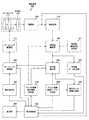
図1は、本発明の実施の形態における撮像装置100の機能構成例を示すブロック図である。撮像装置100は、光学系110と、ズームレンズ制御部112と、ズームレンズ駆動部113と、撮像部120と、顔検出部130と、特定顔識別部140と、特定顔識別辞書記憶部141と、差分値算出部150と、操作アシスト画像生成部160と、特定顔マーカ生成部165と、アシスト画像表示情報保持部170と、表示制御部180と、操作受付部190と、アシスト画像管理テーブル記憶部200と、表示部300とを備える。撮像装置100は、例えば、顔検出機能およびズーム機能を備えるカムコーダ(camcorder:camera and recorder)によって実現することができる。 FIG. 1 is a block diagram illustrating a functional configuration example of an
光学系110は、被写体からの光を集光する複数のレンズ(ズームレンズ111、フォーカスレンズ(図示せず)等)から構成され、入射された被写体からの光がこれらのレンズおよびアイリス(図示せず)を介して撮像部120に供給される。ズームレンズ111は、ズームレンズ駆動部113の駆動に応じて光軸方向に移動し、焦点距離を調整するレンズである。すなわち、ズームレンズ111により、ズーム機能が実現される。 The
ズームレンズ制御部112は、操作受付部190により受け付けられたズーム操作の内容に基づいて、ズームレンズ駆動部113を駆動させるための駆動制御信号を生成し、この駆動制御信号をズームレンズ駆動部113に出力するものである。 The zoom
ズームレンズ駆動部113は、ズームレンズ制御部112から出力された駆動制御信号に応じてズームレンズ111を光軸方向に移動させるものである。 The zoom
撮像部120は、所定の撮像パラメータに従って、被写体からの入射光を変換して撮像画像を生成するものであり、生成された撮像画像を顔検出部130および表示制御部180に出力する。すなわち、撮像部120において、光学系110を介して入射された被写体の光学像が撮像素子(図示せず)の撮像面に結像され、この結像された光学像に対応する撮像信号に対して、信号処理部(図示せず)が所定の信号処理を行うことにより、撮像画像が生成される。 The
顔検出部130は、撮像部120から出力された撮像画像に含まれる人物の顔を検出するものであり、検出された顔に関する顔検出情報を特定顔識別部140に出力する。顔検出方法として、例えば、顔の輝度分布情報が記録されているテンプレートと実画像とのマッチングによる顔検出方法(例えば、特開2004−133637参照。)、撮影画像に含まれる肌色の部分や人間の顔の特徴量等に基づいた顔検出方法等を用いることができる。また、顔検出情報には、検出された顔を含むその周辺画像である顔画像(例えば、図2(b)に示す顔画像401乃至403)と、検出された顔の撮像画像上における位置およびサイズとが含まれる。検出された顔の撮像画像上における位置は、例えば、撮像画像上における顔画像の中心位置とし、検出された顔の撮像画像上におけるサイズは、例えば、撮像画像上における顔画像の水平方向および垂直方向の長さとすることができる。この水平方向および垂直方向の長さにより、検出された顔の面積が特定される。 The
特定顔識別部140は、特定顔識別辞書記憶部141に記憶されている特定顔識別辞書を用いて、顔検出部130により検出された顔が、ユーザにより指定された特定人物の顔(特定顔)であるか否かを識別するものである。また、特定顔識別部140は、顔検出部130により検出された顔が特定顔であると識別した場合には、この特定顔の撮像画像上における位置およびサイズを差分値算出部150および特定顔マーカ生成部165に出力する。ここで、特定顔識別部140は、特定顔識別辞書記憶部141に記憶されている複数の特定顔識別辞書の中から、アシスト画像表示情報保持部170の辞書番号171(図5に示す)に保持されている辞書番号に対応する特定顔識別辞書を用いて識別処理を行う。 The specific
特定顔識別辞書記憶部141は、特定顔識別部140による特定顔識別処理に用いられる複数の特定顔識別辞書を特定顔毎に記憶するものであり、記憶されている特定顔識別辞書を特定顔識別部140に供給する。ここで、特定顔の識別方法として、例えば、特定人物の顔画像から抽出された特徴量に基づいた識別方法を用いることができる。すなわち、特定人物の顔画像から抽出された特徴量を特定顔識別辞書記憶部141に特定顔識別辞書として予め記憶しておく。そして、顔検出部130により検出された顔画像から特徴量が抽出され、この抽出された特徴量と、特定顔識別辞書に含まれる特徴量とが比較されることにより、これらの特徴量の類似度が算出される。そして、この算出された類似度が閾値を超えた場合に、その顔画像が特定顔であると判定される。また、特定顔の識別方法として、顔画像の特徴量を用いた識別方法以外に、例えば、判定対象となる顔画像上の2点間の輝度値の差分値を用いて判別器による識別処理を行う識別方法等を用いることができる。 The specific face identification
アシスト画像管理テーブル記憶部200は、配置アシスト画像および操作アシスト画像を表示部300に表示するための各情報を記憶するものであり、記憶されている各情報を差分値算出部150、操作アシスト画像生成部160および表示制御部180に供給する。ここで、配置アシスト画像は、撮像範囲において、ユーザにより指定された特定顔を配置すべき位置およびサイズを表す人型画像であり、例えば、図4に示す配置アシスト画像222、225、228が表示される。また、操作アシスト画像は、撮像範囲において、ユーザにより指定された特定顔の位置およびサイズのうちの少なくとも1つを変更させるための画像であり、例えば、図7(b)に示す左側移動指示画像441、上側移動指示画像442、ズーム指示画像443が表示される。なお、アシスト画像管理テーブル記憶部200については、図3および図4を参照して詳細に説明する。 The assist image management
差分値算出部150は、特定顔識別部140により識別された特定顔の顔画像と、アシスト画像管理テーブル記憶部200に記憶されている配置アシスト画像により特定される顔領域とを比較することにより、これらの位置およびサイズに関する差分値を算出するものであり、算出された各差分値を操作アシスト画像生成部160に出力する。具体的には、差分値算出部150は、特定顔識別部140から出力された特定顔の顔画像の撮像画像上における位置およびサイズと、アシスト画像管理テーブル記憶部200に記憶されている配置アシスト画像により特定される顔領域の位置およびサイズとを比較することにより、撮像画像上における上下方向の位置の差分値、左右方向の位置の差分値、サイズの差分値のそれぞれを算出する。なお、これらの差分値の算出方法については、図7(a)を参照して詳細に説明する。 The difference
操作アシスト画像生成部160は、アシスト画像管理テーブル記憶部200に記憶されている各閾値を用いて、差分値算出部150から出力された各差分値に基づいて、操作アシスト画像を生成するものであり、生成された操作アシスト画像を表示制御部180に出力する。また、操作アシスト画像生成部160は、差分値算出部150から出力された差分値が、アシスト画像管理テーブル記憶部200に記憶されている閾値以下である場合には、その差分値に対応する操作アシスト画像を生成せずに、その差分値が閾値以下である旨を表示制御部180に出力する。なお、操作アシスト画像の生成については、図7(b)を参照して詳細に説明する。 The operation assist
特定顔マーカ生成部165は、特定顔識別部140から出力された特定顔の顔画像の撮像画像上における位置およびサイズに基づいて、撮像画像における特定顔の位置を示す特定顔マーカを生成するものであり、生成された特定顔マーカを表示制御部180に出力する。 The specific face
アシスト画像表示情報保持部170は、配置アシスト画像または操作アシスト画像を表示部300に順次表示させるための各情報を保持するものであり、保持されている各情報を特定顔識別部140、差分値算出部150および表示制御部180に供給する。また、アシスト画像表示情報保持部170に保持されている各情報は、表示制御部180により順次書き換えられる。なお、アシスト画像表示情報保持部170については、図5を参照して詳細に説明する。 The assist image display
表示制御部180は、撮像部120から出力された撮像画像を表示部300に順次表示させるものである。また、表示制御部180は、アシスト画像表示情報保持部170に保持されている各情報に従って、アシスト画像管理テーブル記憶部200に記憶されている配置アシスト画像を撮像画像上に重ねて順次表示させる。さらに、表示制御部180は、操作アシスト画像生成部160から出力された操作アシスト画像と、特定顔マーカ生成部165から出力された特定顔マーカとを撮像画像上に重ねて表示させる。表示制御部180は、操作受付部190からの操作内容、または、表示部300の表示状態に応じて、アシスト画像表示情報保持部170の内容の書換えを行う。 The
操作受付部190は、ユーザによって操作された操作内容を受け付ける操作受付部であり、受け付けられた操作内容に応じた信号をズームレンズ制御部112または表示制御部180に出力する。操作受付部190として、例えば、ズーム操作を行うためのW(ワイド)ボタンおよびT(テレ)ボタン、特定顔を指定するための特定顔指定ボタン、動画の記録が可能な状態にする動画記録モードの設定または解除を行うための動画記録モード設定/解除ボタン、この動画記録モードにおいてアシスト画像を表示させるアシスト画像表示モードの設定または解除を行うためのアシスト画像表示モード設定/解除ボタン等の操作部材が撮像装置100に備えられている。ここで、Wボタンが押下されている状態では、ズームレンズ制御部112の制御に基づいて、ズームレンズ111がワイド端側(広角側)に移動し、Tボタンが押下されている状態では、ズームレンズ制御部112の制御に基づいて、ズームレンズ111がテレ端側(望遠側)に移動する。 The
表示部300は、表示制御部180の制御に基づいて、撮像画像等の各画像を表示するものである。表示部300は、例えば、LCD(Liquid Crystal Display:液晶ディスプレイ)やEVF(Electronic View Finder:電子ビューファインダ)により実現することができる。なお、操作受付部190の一部または全部と表示部300とをタッチパネルとして一体で構成するようにしてもよい。 The
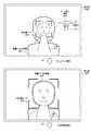
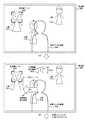
図2は、本発明の実施の形態における特定顔識別辞書記憶部141に記憶されている特定顔識別辞書を用いてユーザにより指定された特定顔を識別する場合を概略的に示す図である。図2(a)には、特定顔識別辞書記憶部141に記憶されている特定顔識別辞書を示し、図2(b)には、撮像部120により生成された撮像画像400を示す。ここで、特定顔識別辞書記憶部141に記憶されている各特定顔識別辞書は、顔検出部130により検出された顔画像について、特定顔識別部140による特定顔識別処理を行うための判定データであるが、図2(a)では、特定顔識別辞書として各特定顔識別辞書に対応する顔を模式的に示す。また、図2(a)では、3人の顔に対応する特定顔識別辞書が特定顔識別辞書記憶部141に記憶されている場合を例にして示す。 FIG. 2 is a diagram schematically showing a case where a specific face specified by the user is identified using the specific face identification dictionary stored in the specific face identification
図2(a)に示すように、特定顔識別辞書記憶部141には、特定顔識別辞書を識別するための辞書番号が特定顔識別辞書に関連付けて記憶されている。例えば、辞書番号として「001」、「002」、「003」が付与されて記憶される。ここで、特定顔識別部140により特定顔識別処理が行われる場合には、特定顔識別辞書記憶部141に記憶されている複数の特定顔識別辞書の中から、ユーザにより指定された少なくとも1つの特定顔に係る特定顔識別辞書を用いて特定顔識別処理が行われる。すなわち、特定顔識別辞書記憶部141に記憶されている複数の特定顔識別辞書の中から、少なくとも1つの特定顔に係る特定顔識別辞書を指定する指定操作が操作受付部190により受け付けられた場合には、この指定された特定顔識別辞書に対応する辞書番号が、アシスト画像表示情報保持部170の辞書番号171(図5に示す)に記録される。そして、特定顔識別部140により特定顔識別処理が行われる場合には、アシスト画像表示情報保持部170の辞書番号171に記録されている辞書番号に対応する特定顔識別辞書を用いて特定顔識別処理が行われる。ここでは、アシスト画像表示情報保持部170の辞書番号171に「001」が記録されている場合を例にして説明する。 As shown in FIG. 2A, the specific face identification
図2(b)に示す撮像画像400には、3人の人物411乃至413が含まれている。このため、人物411乃至413の顔が顔検出部130により検出され、顔画像401乃至403と、これらの位置およびサイズとが特定顔識別部140に出力される。そして、特定顔識別部140は、ユーザにより指定された特定顔の辞書番号「001」に対応する特定顔識別辞書を用いて、顔画像301乃至303について特定顔識別処理を行い、この特定顔識別処理により、ユーザにより指定された特定顔が識別される。例えば、図2(b)に示すように、辞書番号「001」に対応する特定顔識別辞書を表す特定顔と略同一である顔画像401が特定顔として識別される。なお、複数の特定顔を指定しておき、これらの複数の特定顔のうちの少なくとも1つの特定顔を識別するようにしてもよい。 The captured
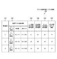
図3は、本発明の実施の形態におけるアシスト画像管理テーブル記憶部200に記憶されている内容を概略的に示す図である。アシスト画像管理テーブル記憶部200には、管理番号210と、配置アシスト画像情報220と、上下移動指示画像表示閾値230と、左右移動指示画像表示閾値240と、ズーム指示画像表示閾値250と、待ち時間カウンタ閾値260とが配置アシスト画像毎に格納されている。なお、本発明の実施の形態では、3種類の配置アシスト画像を用いた例について説明する。 FIG. 3 is a diagram schematically showing the contents stored in the assist image management
管理番号210は、複数種類の配置アシスト画像のそれぞれに付与される識別番号であり、例えば、3種類の配置アシスト画像のそれぞれに対応して管理番号1乃至3が格納される。 The
配置アシスト画像情報220は、配置アシスト画像を表示させるための情報であり、テンプレート画像、顔位置および顔サイズが含まれる。テンプレート画像は、撮像画像に重ねて表示部300に表示される配置アシスト画像のテンプレート画像であり、例えば、管理番号210の「1」乃至「3」に関連付けて、「テンプレート画像A」乃至「テンプレート画像C」が格納される。なお、これらのテンプレート画像については、図4を参照して詳細に説明する。ここで、撮像画像を平面座標とする場合において、配置アシスト画像の顔領域に相当する矩形の中心位置の座標が顔位置に格納される。さらに、その顔領域に相当する矩形の高さおよび幅が顔サイズに格納される。すなわち、顔位置および顔サイズには、配置アシスト画像により特定される顔領域の位置およびサイズが格納される。 The placement assist
上下移動指示画像表示閾値230は、撮像画像において特定顔の人物を上下方向に移動させるための指標となる上側移動指示画像または下側移動指示画像を表示するか否かを判定する場合に用いられる閾値である。 The vertical movement instruction
左右移動指示画像表示閾値240は、撮像画像において特定顔の人物を左右方向に移動させるための指標となる左側移動指示画像または右側移動指示画像を表示するか否かを判定する場合に用いられる閾値である。 The left-right movement instruction
ズーム指示画像表示閾値250は、撮像画像において特定顔の人物を拡大または縮小するためにズーム操作を行わせるための指標となるズーム指示画像を表示するか否かを判定する場合に用いられる閾値である。なお、上下移動指示画像表示閾値230、左右移動指示画像表示閾値240およびズーム指示画像表示閾値250の各閾値については、管理番号210の「1」乃至「3」に応じて、その値を変更するようにしてもよく、管理番号210の「1」乃至「3」のそれぞれについて同一の値を使用するようにしてもよい。 The zoom instruction
待ち時間カウンタ閾値260は、表示部300に表示されている配置アシスト画像に特定顔が合致した後に、次の配置アシスト画像に切り換える際に用いられる閾値である。すなわち、この閾値は、配置アシスト画像に特定顔が合致してから、次の配置アシスト画像に切り換えるまでの待ち時間を示す値である。 The waiting time
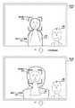
図4は、本発明の実施の形態におけるアシスト画像管理テーブル記憶部200に記憶されている配置アシスト画像を含むテンプレート画像の例を示す図である。本発明の実施の形態では、撮像範囲の中央部分で、撮像画像に含まれる人物の特定顔を次第に大きくするための配置アシスト画像を順次表示させる場合を例にして示す。図4(a)には、管理番号210の「1」に対応するテンプレート画像A(221)を示し、図4(b)には、管理番号210の「2」に対応するテンプレート画像B(224)を示し、図4(c)には、管理番号210の「3」に対応するテンプレート画像C(227)を示す。 FIG. 4 is a diagram illustrating an example of a template image including an arrangement assist image stored in the assist image management
テンプレート画像A(221)には配置アシスト画像222が含まれ、この配置アシスト画像222が撮像画像に重ねられて表示部300に表示される。また、テンプレート画像A(221)に示す矩形223は、配置アシスト画像222の顔部分に相当する領域であり、この領域により特定される位置およびサイズが、配置アシスト画像情報220の顔位置および顔サイズに格納される。具体的には、配置アシスト画像情報220の顔位置(X1,Y1)には、矩形223の中心位置である顔位置O1が格納され、配置アシスト画像情報220の顔サイズ(H1,W1)には、矩形223の左右方向の長さ(幅)W1および上下方向の長さ(高さ)が格納される。また、テンプレート画像B(224)における配置アシスト画像225および矩形226の関係と、テンプレート画像C(227)における配置アシスト画像228および矩形229の関係とについても、テンプレート画像A(221)における配置アシスト画像222および矩形223の関係と同様であるため、ここでの説明を省略する。ここで、例えば、配置アシスト画像222は、特定人物の全身が写るように記録する場合に表示される画像であり、配置アシスト画像225は、特定人物をバストアップで記録する場合に表示される画像であり、配置アシスト画像228は、特定人物の顔がアップになるように記録する場合に表示される画像である。 The template image A (221) includes an
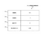
図5は、本発明の実施の形態におけるアシスト画像表示情報保持部170に保持されている内容を概略的に示す図である。アシスト画像表示情報保持部170には、辞書番号171と、管理番号172と、合致フラグ173と、待ち時間カウンタ174とが保持される。 FIG. 5 is a diagram schematically showing the contents held in the assist image display
辞書番号171は、特定顔識別辞書記憶部141に記憶されている複数の特定顔識別辞書の中のユーザにより指定された特定顔識別辞書に対応する辞書番号であり、図5では、特定顔識別辞書記憶部141に記憶されている辞書番号「001」に対応する特定顔識別辞書が指定されている場合を示す。ここで、辞書番号171の内容は、操作受付部190からの指定操作に応じて表示制御部180により書換えが行われる。 The
管理番号172は、アシスト画像管理テーブル記憶部200に記憶されている複数の管理番号の中の現在選択されている管理番号であり、図5では、アシスト画像管理テーブル記憶部200に記憶されている管理番号「1」が現在選択されている場合を示す。 The
合致フラグ173は、管理番号172に格納されている管理番号に対応する配置アシスト画像(表示部300に表示されている配置アシスト画像)に特定顔が一致したか否かを示すフラグである。ここで、配置アシスト画像に特定顔が一致する場合とは、差分値算出部150により算出された各差分値が、管理番号172に格納されている管理番号に対応してアシスト画像管理テーブル記憶部200に記憶されている上下移動指示画像表示閾値230、左右移動指示画像表示閾値240およびズーム指示画像表示閾値250のそれぞれ対応する閾値以下である場合を意味する。例えば、管理番号172に格納されている管理番号に対応する配置アシスト画像に特定顔が一致した場合には表示制御部180により「1」が格納され、その配置アシスト画像に特定顔が一致していない場合には表示制御部180により「0」が格納される。なお、図5では、その配置アシスト画像に特定顔が一致していない場合を示す。 The
待ち時間カウンタ174は、管理番号172に格納されている管理番号に対応する配置アシスト画像に特定顔が一致してからの経過時間を示すカウンタである。すなわち、待ち時間カウンタ174には、合致フラグ173に「1」が格納されてからの経過時間が表示制御部180により格納され、この経過時間が、管理番号172に格納されている管理番号に対応する待ち時間カウンタ閾値260の値に達した場合には、管理番号172に格納されている管理番号が表示制御部180により次の番号に書き換えられ、合致フラグ173に「0」が格納される。 The waiting time counter 174 is a counter that indicates an elapsed time after the specific face matches the placement assist image corresponding to the management number stored in the
図6、図7(b)、図8乃至図14は、本発明の実施の形態における表示部300の表示例を示す図である。また、図7(a)は、操作アシスト画像を表示させるための差分値を算出する算出方法を概略的に示す図である。なお、これらの表示例は、動画記録モードが設定されている場合において、モニタリング状態、または、動画記録中における表示例である。 FIGS. 6, 7B, and 8 to 14 are diagrams showing display examples of the
図6(a)には、アシスト画像表示モードが設定されている場合において、図2(b)に示す撮像画像400が表示部300に表示されている状態を示す。この例では、辞書番号「001」の特定顔識別辞書がユーザにより指定されている場合において、人物411の顔が特定顔として識別され、この顔に特定顔マーカ420が付されている場合を示す。ここで、アシスト画像表示モードを設定する操作入力が操作受付部190により受け付けられた場合には、図6(b)に示すように、アシスト画像表示情報保持部170の管理番号172に保持されている管理番号に対応するテンプレート画像に含まれる配置アシスト画像が撮像画像に重ねて表示される。例えば、図5に示すように、管理番号172に「1」が格納されている場合には、図4に示すテンプレート画像A(221)に含まれる配置アシスト画像222が表示制御部180により表示部300に表示される。 FIG. 6A shows a state where the captured
図7(a)には、図6(b)に示す表示例の場合における配置アシスト画像222と、特定顔の顔画像401との差分値を算出する算出方法を概略的に示す。また、図7(a)には、図6(b)に示す表示例のうちの人物411および配置アシスト画像222のみを示し、図6(b)に示す撮像画像と同じ大きさの範囲を撮像範囲430として示す。ここで、本発明の実施の形態では、配置アシスト画像および特定顔の顔画像の差分値として、撮像画像上における配置アシスト画像情報220の顔位置と、特定顔の顔画像の中心位置との左右方向および上下方向の差分値と、撮像画像上における配置アシスト画像情報220の顔サイズにより特定される面積と、特定顔の顔画像の面積との差分値を用いる場合を例にして説明する。具体的に、撮像範囲430の左上角を原点(0,0)とし、左右方向をx軸、上下方向をy軸としたxy平面座標上において、特定顔の顔画像401の中心位置を座標(X11,Y11)とし、特定顔の顔画像401の上下方向の長さを高さH11とし、左右方向の長さを幅W11とする。これらの値は、顔検出部130により検出される。この場合に、配置アシスト画像222の顔位置O1(X1,Y1)と、特定顔の顔画像401の中心位置座標(X11,Y11)との上下方向の差分値はJ11であり、左右方向の差分値はS11である。また、配置アシスト画像222の顔サイズにより特定される面積と、特定顔の顔画像401の面積との差分値は、「(W1×H1)−(W11×H11)」により求めることができる。このように、特定顔の顔画像の位置およびサイズと、配置アシスト画像により特定される顔領域の位置およびサイズとに基づいて、差分値算出部150が各差分値を算出する。そして、操作アシスト画像生成部160が、これらの差分値に基づいて操作アシスト画像を生成し、表示制御部180が、生成された操作アシスト画像を撮像画像に重ねて表示部300に表示させる。FIG. 7A schematically shows a calculation method for calculating a difference value between the arrangement assist
具体的には、上下方向の差分値J11の絶対値が、管理番号210の「1」に対応して上下移動指示画像表示閾値230に格納されている「J1」の値よりも大きい場合には、移動すべき方向を示す操作アシスト画像が生成される。ここで、配置アシスト画像222の顔位置O1(X1,Y1)を基準とした場合において、上下方向の差分値J11の絶対値が「J1」の値よりも大きい場合に、上下方向の差分値J11が正の値であれば、撮像装置100を上側にチルティングすることを示す上側移動指示画像が生成され、上下方向の差分値J11が負の値であれば、撮像装置100を下側にチルティングすることを示す下側移動指示画像が生成される。例えば、図7(a)に示す例では、上下方向の差分値J11が正の値であるため、撮像装置100を上側にチルティングすることを示す上側移動指示画像442(図7(b)に示す)が生成される。ここで、上側移動指示画像442の上下方向の長さAJ11は、上下方向の差分値J11に応じて決定される。この差分値J11が大きくなるに応じて、上側移動指示画像442の上下方向の長さAJ11が長くなる。そして、図7(b)に示すように、上側移動指示画像442が撮像画像に重ねて表示部300に表示される。ここで、チルティングは、撮影者の撮影位置を変更しない状態で、上下方向に撮像装置100を振ることを意味する。 Specifically, when the absolute value of the difference value J11 in the vertical direction is larger than the value of “J1” stored in the vertical movement instruction
同様に、左右方向の差分値S11の絶対値が、管理番号210の「1」に対応して左右移動指示画像表示閾値240に格納されている「S1」の値よりも大きい場合には、移動すべき方向を示す操作アシスト画像が生成される。ここで、配置アシスト画像222の顔位置O1(X1,Y1)を基準とした場合において、左右方向の差分値S11の絶対値が「S1」の値よりも大きい場合に、左右方向の差分値S11が正の値であれば、撮像装置100を左側にパンニングすることを示す左側移動指示画像が生成され、左右方向の差分値S11が負の値であれば、撮像装置100を右側にパンニングすることを示す右側移動指示画像が生成される。例えば、図7(a)に示す例では、左右方向の差分値S11が正の値であるため、撮像装置100を左側にパンニングすることを示す左側移動指示画像441(図7(b)に示す)が生成される。ここで、左側移動指示画像441の左右方向の長さAS11は、左右方向の差分値S11に応じて決定される。そして、図7(b)に示すように、左側移動指示画像441が撮像画像に重ねて表示部300に表示される。ここで、パンニングは、撮影者の撮影位置を変更しない状態で、水平方向に撮像装置100を振ることを意味する。 Similarly, when the absolute value of the difference value S11 in the left-right direction is larger than the value of “S1” stored in the left-right movement instruction
また、配置アシスト画像222の顔サイズにより特定される面積と、特定顔の顔画像401の面積との差分値の絶対値が、管理番号210の「1」に対応してズーム指示画像表示閾値250に格納されている「Z1」の値よりも大きい場合には、ズーム操作をすべき操作量を示す操作アシスト画像が生成される。ここで、配置アシスト画像222の顔サイズ(H1,W1)により特定される面積を基準とした場合において、面積の差分値の絶対値が「Z1」の値よりも大きい場合に、その面積の差分値が正の値であれば、ズームアップ操作(拡大操作)することを示すズーム指示画像が生成され、その面積の差分値が負の値であれば、ズームダウン操作(縮小操作)することを示すズーム指示画像が生成される。例えば、図7(a)に示す例では、その面積の差分値が正の値であるため、ズームアップ操作(拡大操作)することを示すズーム指示画像443(図7(b)に示す)が生成される。ここで、ズーム指示画像443の上下方向の長さHW11は、その面積の差分値に応じて決定される。すなわち、その面積の差分値が大きくなるに応じて、ズーム指示画像443の上下方向の長さHW11が長くなる。そして、図7(b)に示すように、ズーム指示画像443が撮像画像に重ねて表示部300に表示される。なお、図7(b)では、左側移動指示画像441を配置アシスト画像222の左側に配置し、上側移動指示画像442を配置アシスト画像222の上側に配置し、ズーム指示画像443を配置アシスト画像222の右側に配置する例を示すが、他の配置とするようにしてもよい。例えば、顔が検出されていない領域に操作アシスト画像を配置するようにしてもよい。また、この例では、差分値に応じて操作アシスト画像の長さを変更する場合を示すが、例えば、差分値に応じた操作アシスト画像の太さや透過率の変更等により、ユーザに操作量を通知するようにしてもよい。 In addition, the absolute value of the difference value between the area specified by the face size of the placement assist
図8(a)には、図7(b)に示す左側移動指示画像441に従って、ユーザにより撮像装置100が左側にパンニングされた後の表示例を示す。図8(a)に示すように、左右方向の差分値S11の絶対値が、管理番号210の「1」に対応して左右移動指示画像表示閾値240に格納されている「S1」の値の範囲内になった場合には、左側移動指示画像441が消去される。ここで、例えば、ユーザにより撮像装置100が左側にパンニングされている途中でパンニング操作が中止された場合において、左右方向の差分値S11の絶対値が「S1」の値よりも大きい場合には、左右方向の差分値S11に応じて、左側移動指示画像441の長さが短縮されて表示される。なお、図8(a)に示す例では、上下方向の差分値および面積(サイズ)の差分値については変更がないため、図7(b)と同様に、上側移動指示画像442およびズーム指示画像443が継続して表示される。 FIG. 8A shows a display example after the
図8(b)には、図8(a)に示す上側移動指示画像442に従って、ユーザにより撮像装置100が上側にチルティングされた後の表示例を示す。図8(b)に示すように、上下方向の差分値J11の絶対値が、管理番号210の「1」に対応して上下移動指示画像表示閾値230に格納されている「J1」の値の範囲内になった場合には、上側移動指示画像442が消去される。ここで、例えば、ユーザにより撮像装置100が上側にチルティングされている途中でチルティング操作が中止された場合において、上下方向の差分値J11の絶対値が「J1」の値よりも大きい場合には、上下方向の差分値J11に応じて、上側移動指示画像442の長さが短縮されて表示される。なお、図8(b)に示す例では、面積の差分値については変更がないため、図8(a)と同様に、ズーム指示画像443が継続して表示される。 FIG. 8B shows a display example after the
図9(a)には、図8(b)に示すズーム指示画像443に従って、ユーザにより操作受付部190からズームアップ操作がされた後の表示例を示す。図9(a)に示すように、面積の差分値の絶対値が、管理番号210の「1」に対応してズーム指示画像表示閾値250に格納されている「Z1」の値の範囲内になった場合には、ズーム指示画像443が消去される。ここで、例えば、ユーザにより操作受付部190からズームアップ操作がされている途中でズームアップ操作が中止された場合において、面積の差分値の絶対値が「Z1」の値よりも大きい場合には、面積の差分値に応じて、ズーム指示画像443の長さが短縮されて表示される。このように、図9(a)に示す例では、上下左右方向およびサイズの各差分値が、管理番号210の「1」に対応する各閾値の範囲内になったため、左側移動指示画像441、上側移動指示画像442、ズーム指示画像443の全てが消去される。 FIG. 9A shows a display example after the user performs a zoom-up operation from the
図9(b)には、図9(a)に示す表示状態で、アシスト画像表示モードを解除する操作入力が操作受付部190により受け付けられた後の表示例を示す。このように、アシスト画像表示モードを解除する操作入力が受け付けられた場合には、配置アシスト画像222が消去される。なお、左側移動指示画像441、上側移動指示画像442、ズーム指示画像443等の操作アシスト画像が表示されている場合には、これらの操作アシスト画像も消去される。このように、特定顔がユーザの好みの配置となった場合には、アシスト画像表示モードを解除する操作入力を行うことにより、撮像画像のみを表示させることができる。 FIG. 9B shows a display example after an operation input for canceling the assist image display mode is received by the
図10(b)には、図10(a)に示す表示状態で、アシスト画像表示モードを解除する操作入力がなく、一定時間(図3に示す待ち時間カウンタ閾値260の「T1」)が経過した後の表示例を示す。なお、図10(a)に示す表示例は、図9(a)に示す表示例と同一である。図10(a)に示すように、配置アシスト画像222の顔領域に特定顔が合致してから、管理番号210の「1」に対応して待ち時間カウンタ閾値260に格納されている「T1」の時間が経過した場合には、配置アシスト画像222が消去され、管理番号210の「2」に対応して配置アシスト画像情報220のテンプレート画像に格納されているテンプレート画像B(224)に含まれる配置アシスト画像225が撮像画像に重ねて表示部300に表示される。すなわち、配置アシスト画像の顔領域に特定顔が合致してから一定時間が経過した場合には、管理番号210の順序に従って、配置アシスト画像が切り換えて表示される。そして、切り換え後の配置アシスト画像と、特定顔との各差分値が算出され、各差分値に基づいて操作アシスト画像が表示される。なお、配置アシスト画像の顔領域に特定顔が合致してから一定時間が経過した場合には、動画記録中であることを条件に、配置アシスト画像を切り換えるようにしてもよい。 In FIG. 10B, there is no operation input for canceling the assist image display mode in the display state shown in FIG. 10A, and a fixed time (“T1” of the waiting
図11(a)には、切り換え後の配置アシスト画像と特定顔との各差分値に基づいて生成された操作アシスト画像の表示例を示す。図11(a)に示す表示例では、操作アシスト画像としてズーム指示画像451が表示されている場合を示す。ここで、ズーム指示画像451の長さHW21は、図7(a)に示す算出方法と同様に算出された差分値により決定される。また、図11(a)に示す表示例では、上下方向および左右方向の何れの差分値も閾値を超えていないため、上下方向および左右方向に移動させるための操作アシスト画像は表示されない。ここで、例えば、特定顔の人物411が撮像画像上の左側方向に移動した場合において、左右方向の差分値の絶対値が、管理番号210の「2」に対応して左右移動指示画像表示閾値240に格納されている「S2」の値よりも大きくなった場合には、図11(b)に示すように、左側移動指示画像452が表示される。なお、左側移動指示画像452の長さAS21は、左右方向の差分値に応じて決定される。また、ユーザにより撮像装置100が上下左右方向に移動された場合等についても、各差分値が算出され、この各差分値に基づいて操作アシスト画像が表示される。 FIG. 11A shows a display example of the operation assist image generated based on each difference value between the switched placement assist image and the specific face. The display example shown in FIG. 11A shows a case where a zoom instruction image 451 is displayed as an operation assist image. Here, the length HW21 of the zoom instruction image 451 is determined by the difference value calculated in the same manner as the calculation method shown in FIG. Further, in the display example shown in FIG. 11A, since the difference value in the vertical direction and the horizontal direction does not exceed the threshold value, the operation assist image for moving in the vertical direction and the horizontal direction is not displayed. Here, for example, when the
図12(a)には、図11(b)に示す左側移動指示画像452に従って、ユーザにより撮像装置100が左側にパンニングされた後の表示例を示す。図12(a)に示すように、左右方向の差分値の絶対値が、管理番号210の「2」に対応して左右移動指示画像表示閾値240に格納されている「S2」の値の範囲内になった場合には、左側移動指示画像452が消去される。なお、図12(a)に示す例では、面積の差分値については変更がないため、図11(b)と同様に、ズーム指示画像451が継続して表示される。 FIG. 12A shows a display example after the
図12(b)には、図12(a)に示すズーム指示画像451に従って、ユーザにより操作受付部190からズームアップ操作がされた後の表示例を示す。図12(b)に示すように、面積の差分値の絶対値が、管理番号210の「2」に対応してズーム指示画像表示閾値250に格納されている「Z2」の値の範囲内になった場合には、ズーム指示画像451が消去される。このように、図12(b)に示す例では、上下左右方向およびサイズの各差分値が、管理番号210の「2」に対応する各閾値の範囲内になったため、左側移動指示画像、上側移動指示画像、ズーム指示画像の全てが消去される。 FIG. 12B shows a display example after the user performs a zoom-up operation from the
図13(a)には、図12(b)に示す表示状態で、アシスト画像表示モードを解除する操作入力がなく、一定時間(図3に示す待ち時間カウンタ閾値260の「T2」)が経過した後の表示例を示す。図13(a)に示すように、配置アシスト画像222の顔領域に特定顔が合致してから、管理番号210の「2」に対応して待ち時間カウンタ閾値260に格納されている「T2」の時間が経過した場合には、配置アシスト画像225が消去され、管理番号210の「3」に対応して配置アシスト画像情報220のテンプレート画像に格納されているテンプレート画像C(227)に含まれる配置アシスト画像228が撮像画像に重ねて表示部300に表示される。そして、切り換え後の配置アシスト画像と、特定顔との各差分値が算出され、各差分値に基づいて操作アシスト画像が表示される。 In FIG. 13A, there is no operation input for canceling the assist image display mode in the display state shown in FIG. 12B, and a fixed time (“T2” of the waiting
図13(b)には、切り換え後の配置アシスト画像と特定顔との各差分値に基づいて生成された操作アシスト画像の表示例を示す。図13(b)に示す表示例では、操作アシスト画像としてズーム指示画像461が表示されている場合を示す。ここで、ズーム指示画像461の長さHW31は、図7(a)に示す算出方法と同様に算出された差分値により決定される。また、図13(b)に示す表示例では、上下方向および左右方向の何れの差分値も閾値を超えていないため、上下方向および左右方向に移動させるための操作アシスト画像は表示されない。 FIG. 13B shows a display example of the operation assist image generated based on each difference value between the placement assist image after switching and the specific face. The display example shown in FIG. 13B shows a case where the zoom instruction image 461 is displayed as the operation assist image. Here, the length HW31 of the zoom instruction image 461 is determined by the difference value calculated in the same manner as the calculation method shown in FIG. In the display example shown in FIG. 13B, since the difference values in the vertical direction and the horizontal direction do not exceed the threshold value, the operation assist image for moving in the vertical direction and the horizontal direction is not displayed.
図14(a)には、図13(b)に示すズーム指示画像461に従って、ユーザにより操作受付部190からズームアップ操作がされた後の表示例を示す。図14(a)に示すように、面積の差分値の絶対値が、管理番号210の「3」に対応してズーム指示画像表示閾値250に格納されている「Z3」の値の範囲内になった場合には、ズーム指示画像461が消去される。このように、図14(a)に示す例では、上下左右方向およびサイズの各差分値が、管理番号210の「1」に対応する各閾値の範囲内になったため、左側移動指示画像、上側移動指示画像、ズーム指示画像の全てが消去される。 FIG. 14A shows a display example after the user performs a zoom-up operation from the
図14(b)には、図14(b)に示す表示状態で、アシスト画像表示モードを解除する操作入力がなく、一定時間(図3に示す待ち時間カウンタ閾値260の「T3」)が経過した後の表示例を示す。図14(b)に示すように、配置アシスト画像228の顔領域に特定顔が合致してから、管理番号210の「3」に対応して待ち時間カウンタ閾値260に格納されている「T3」の時間が経過した場合には、配置アシスト画像228が消去され、管理番号210の「1」に対応して配置アシスト画像情報220のテンプレート画像に格納されているテンプレート画像A(221)に含まれる配置アシスト画像222が撮像画像に重ねて表示部300に表示される。このように、現在表示されている配置アシスト画像に対応する管理番号210が最下端の番号「3」である場合には、管理番号210の最上端の番号「1」に戻るように切替えが行われる。ここで、現在表示されている配置アシスト画像に対応する管理番号210が最下端の番号「3」である場合には、管理番号210の最上端の番号「1」に戻る切替えを行わず、アシスト画像表示モードを自動で解除するようにしてもよい。 In FIG. 14B, there is no operation input for canceling the assist image display mode in the display state shown in FIG. 14B, and a fixed time (“T3” of the waiting
次に、本発明の実施の形態における撮像装置100の動作について図面を参照して説明する。 Next, the operation of the
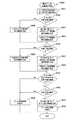
図15は、本発明の実施の形態における撮像装置100によるアシスト画像表示処理の処理手順を示すフローチャートである。この例では、ユーザにより指定された特定顔に係る特定顔識別辞書の辞書番号が、アシスト画像表示情報保持部170の辞書番号171に格納されている場合について説明する。また、この例では、動画記録モードおよびアシスト画像表示モードがユーザにより設定されている場合について説明する。 FIG. 15 is a flowchart showing a processing procedure of assist image display processing by the
最初に、表示制御部180が、アシスト画像表示情報保持部170の管理番号172を「1」に初期化し(ステップS901)、アシスト画像表示情報保持部170の合致フラグ173および待ち時間カウンタ174を「0」に初期化する(ステップS902)。続いて、撮像部120が撮像画像を生成し(ステップS903)、表示制御部180が、アシスト画像表示情報保持部170の管理番号172に格納されている管理番号に対応してアシスト画像管理テーブル記憶部200に記憶されているテンプレート画像の配置アシスト画像を撮像画像に重ねて表示部300に表示する(ステップS904)。 First, the
また、顔検出部130が、撮像部120により生成された撮像画像から顔を検出する顔検出処理を行う(ステップS905)。そして、撮像画像から顔が検出された場合には(ステップS906)、特定顔識別部140が、指定された特定顔に係る特定顔識別辞書を用いて、検出された顔について顔識別処理を行う(ステップS907)。そして、検出された顔が特定顔であると識別された場合には(ステップS908)、操作アシスト画像表示処理が行われる(ステップS920)。この操作アシスト画像表示処理については、図16を参照して詳細に説明する。続いて、配置アシスト画像更新処理が行われる(ステップS940)。この配置アシスト画像更新処理については、図17を参照して詳細に説明する。 Further, the
一方、撮像画像から顔が検出されない場合(ステップS906)、または、検出された顔が特定顔であると識別されない場合には(ステップS908)、表示制御部180が、撮像画像に重ねて表示されている各操作アシスト画像を消去する(ステップS909)。 On the other hand, when a face is not detected from the captured image (step S906) or when the detected face is not identified as a specific face (step S908), the
続いて、表示制御部180が、動画記録モードが解除されたか否かを判断し(ステップS910)、動画記録モードが解除されていない場合には、アシスト画像表示モードが解除されたか否かを判断する(ステップS911)。動画記録モードが解除された場合(ステップS910)、または、アシスト画像表示モードが解除された場合には(ステップS911)、アシスト画像表示処理の動作を終了する。一方、動画記録モードが解除されておらず(ステップS910)、アシスト画像表示モードが解除されていない場合には(ステップS911)、ステップS903に戻る。 Subsequently, the
図16は、本発明の実施の形態における撮像装置100によるアシスト画像表示処理の処理手順のうちの操作アシスト画像表示処理手順(図15に示すステップS920の処理手順)を示すフローチャートである。 FIG. 16 is a flowchart showing an operation assist image display processing procedure (processing procedure of step S920 shown in FIG. 15) in the assist image display processing procedure by the
最初に、差分値算出部150が、アシスト画像表示情報保持部170の管理番号172に格納されている管理番号に対応してアシスト画像管理テーブル記憶部200に記憶されている顔位置および顔サイズと、特定顔であると識別された顔画像の位置およびサイズとを比較することにより、左右方向および上下方向の差分値と、サイズの差分値とを算出する(ステップS921)。続いて、操作アシスト画像生成部160が、算出された上下方向の差分値が、アシスト画像表示情報保持部170の管理番号172に格納されている管理番号に対応してアシスト画像管理テーブル記憶部200に記憶されている上下移動指示画像表示閾値230の値以下であるか否かを判断する(ステップS922)。算出された上下方向の差分値が上下移動指示画像表示閾値230の値以下でない場合には(ステップS922)、操作アシスト画像生成部160が、算出された上下方向の差分値に基づいて上側移動指示画像または下側移動指示画像を生成する(ステップS923)。そして、表示制御部180が、生成された上側移動指示画像または下側移動指示画像を撮像画像に重ねて表示部300に表示する(ステップS924)。一方、算出された上下方向の差分値が上下移動指示画像表示閾値230の値以下である場合には(ステップS922)、表示制御部180が、現在表示されている上側移動指示画像または下側移動指示画像を消去する(ステップS925)。なお、上側移動指示画像または下側移動指示画像が表示されていない場合には、この消去処理は行わない。 First, the difference
続いて、操作アシスト画像生成部160が、算出された左右方向の差分値が、アシスト画像表示情報保持部170の管理番号172に格納されている管理番号に対応してアシスト画像管理テーブル記憶部200に記憶されている左右移動指示画像表示閾値240の値以下であるか否かを判断する(ステップS926)。算出された左右方向の差分値が左右移動指示画像表示閾値240の値以下でない場合には(ステップS926)、操作アシスト画像生成部160が、算出された左右方向の差分値に基づいて左側移動指示画像または右側移動指示画像を生成する(ステップS927)。そして、表示制御部180が、生成された左側移動指示画像または右側移動指示画像を撮像画像に重ねて表示部300に表示する(ステップS928)。一方、算出された左右方向の差分値が左右移動指示画像表示閾値240の値以下である場合には(ステップS926)、表示制御部180が、現在表示されている左側移動指示画像または右側移動指示画像を消去する(ステップS929)。なお、左側移動指示画像または右側移動指示画像が表示されていない場合には、この消去処理は行わない。 Subsequently, the assist image management
続いて、操作アシスト画像生成部160が、算出されたサイズの差分値が、アシスト画像表示情報保持部170の管理番号172に格納されている管理番号に対応してアシスト画像管理テーブル記憶部200に記憶されているズーム指示画像表示閾値250の値以下であるか否かを判断する(ステップS930)。算出されたサイズの差分値がズーム指示画像表示閾値250の値以下でない場合には(ステップS930)、操作アシスト画像生成部160が、算出されたサイズの差分値に基づいてズーム指示画像を生成する(ステップS931)。そして、表示制御部180が、生成されたズーム指示画像を撮像画像に重ねて表示部300に表示する(ステップS932)。一方、算出されたサイズの差分値がズーム指示画像表示閾値250の値以下である場合には(ステップS930)、表示制御部180が、現在表示されているズーム指示画像を消去する(ステップS933)。なお、ズーム指示画像が表示されていない場合には、この消去処理は行わない。 Subsequently, the operation assist
図17は、本発明の実施の形態における撮像装置100によるアシスト画像表示処理の処理手順のうちの配置アシスト画像更新処理手順(図15に示すステップS940の処理手順)を示すフローチャートである。 FIG. 17 is a flowchart illustrating an arrangement assist image update processing procedure (the processing procedure of step S940 shown in FIG. 15) in the assist image display processing procedure by the
最初に、表示制御部180が、アシスト画像表示情報保持部170の合致フラグ173の値を取得し(ステップS941)、合致フラグ173の値が「1」であるか否かを判断する(ステップS942)。合致フラグ173の値が「1」である場合には(ステップS942)、表示制御部180が、動画記録の動作中であるか否かを判断し(ステップS943)、動画記録の動作中である場合には、アシスト画像表示情報保持部170の待ち時間カウンタ174の値をインクリメントし(ステップS944)、インクリメント後の待ち時間カウンタ174の値が、アシスト画像表示情報保持部170の管理番号172に格納されている管理番号に対応してアシスト画像管理テーブル記憶部200に記憶されている待ち時間カウンタ閾値260の値以上であるか否かを判断する(ステップS945)。待ち時間カウンタ174の値が待ち時間カウンタ閾値260の値以上である場合には(ステップS945)、表示制御部180が、アシスト画像表示情報保持部170の管理番号172の値に「1」を加算し(ステップS946)、アシスト画像表示情報保持部170の合致フラグ173および待ち時間カウンタ174を「0」に初期化する(ステップS947)。ここで、アシスト画像表示情報保持部170の管理番号172の値が最大値(例えば、図3に示す場合には「3」)となっている場合には、管理番号172の値に「1」を格納する(ステップS946)。 First, the
一方、動画記録の動作中でない場合(ステップS943)、または、待ち時間カウンタ174の値が待ち時間カウンタ閾値260の値以上でない場合には(ステップS945)、図15に示すステップS910に進む。 On the other hand, when the moving image recording is not in operation (step S943), or when the value of the waiting time counter 174 is not equal to or larger than the value of the waiting time counter threshold 260 (step S945), the process proceeds to step S910 shown in FIG.
また、合致フラグ173の値が「1」である場合には(ステップS942)、表示制御部180が、操作アシスト画像生成部160からの出力に基づいて、差分値算出部150により算出された各差分値が、アシスト画像表示情報保持部170の管理番号172に格納されている管理番号に対応してアシスト画像管理テーブル記憶部200に記憶されている上下移動指示画像表示閾値230、左右移動指示画像表示閾値240およびズーム指示画像表示閾値250のそれぞれ対応する閾値以下であるか否かを判断する(ステップS948)。差分値算出部150により算出された各差分値が、それぞれ対応する閾値以下である場合には(ステップS948)、表示制御部180が、アシスト画像表示情報保持部170の合致フラグ173の値に「1」を設定する(ステップS949)。一方、差分値算出部150により算出された各差分値が、それぞれ対応する閾値以下でない場合には(ステップS948)、図15に示すステップS910に進む。 When the value of the
以上では、上下方向および左右方向の差分値と、サイズの差分値との双方が閾値を超えている場合には、上下方向および左右方向に移動させるための操作アシスト画像と、ズーム操作をユーザに行わせるための操作アシスト画像とを同時に表示する例を示した。ここで、撮像装置100により記録された撮像動画は、例えば、テレビジョン等の視聴装置により視聴することができる。例えば、近年、広く普及している大型のテレビジョンを用いて撮像装置100により記録された撮像動画を視聴する場合には、広い画面上に撮像画像自体が大きく表示される。このため、撮像装置100の表示部300においてユーザが撮影中に見ていた撮像画像と、そのテレビジョンに表示される撮像画像とは撮像画像自体の大きさが異なる。このため、撮像装置100の表示部300においてユーザが撮影中に見ていた撮像画像上では、対象物の移動量(ズーム量を含む)が小さい場合でも、そのテレビジョンに表示される撮像画像上では、対象物の移動量が大きくなる場合がある。このように対象物の移動量が大きい場合に、移動している対象物に対して広い画面上を目で追うと、視聴者が見難いおそれがある。そこで、撮像動画を視聴者が見易くするため、撮像装置100により撮像動画を記録する場合には、左右方向のパンニング、上下方向のチルティング、ズーム操作等を比較的ゆっくりと行うことが重要となる。 In the above, when both the vertical and horizontal difference values and the size difference value exceed the threshold, the operation assist image for moving in the vertical direction and the horizontal direction and the zoom operation are displayed to the user. The example which displayed the operation assistance image for making it perform simultaneously was shown. Here, the captured moving image recorded by the
そこで、以下では、上下方向および左右方向の差分値と、サイズの差分値との双方が閾値を超えている場合には、上下方向および左右方向に移動させるための操作アシスト画像のみを表示させ、上下方向および左右方向の差分値が閾値以下であり、サイズの差分値が閾値を超えている場合にのみ、ズーム操作をユーザに行わせるための操作アシスト画像を表示させる例について説明する。これにより、左右方向のパンニングおよび上下方向のチルティングと、ズーム操作とを分けてユーザに行わせることができ、比較的ゆっくりとした操作を行わせることができる。 Therefore, in the following, when both the vertical and horizontal difference values and the size difference value exceed the threshold, only the operation assist image for moving in the vertical and horizontal directions is displayed. An example in which an operation assist image for allowing the user to perform a zoom operation is displayed only when the difference value between the vertical direction and the horizontal direction is equal to or smaller than the threshold value and the size difference value exceeds the threshold value will be described. Thereby, the panning in the horizontal direction and the tilting in the vertical direction and the zoom operation can be performed separately by the user, and a relatively slow operation can be performed.
図18および図19は、本発明の実施の形態における表示部300の表示例を示す図である。なお、図18(a)に示す表示例は、図6(b)に示す表示例と同一であり、図19(b)に示す表示例は、図9(a)に示す表示例と同一である。 18 and 19 are diagrams showing display examples of the
図18(a)に示すように、例えば、アシスト画像表示情報保持部170の管理番号172に保持されている管理番号「1」に対応するテンプレート画像A(221)に含まれる配置アシスト画像222が撮像画像に重ねて表示される。そして、図7(a)に示す算出方法と同様に算出された差分値に基づいて、図18(b)に示すように、左側移動指示画像441および上側移動指示画像442が撮像画像に重ねて表示部300に表示される。ここで、配置アシスト画像222の顔サイズにより特定される面積と、特定顔の顔画像401の面積との差分値の絶対値が、管理番号210の「1」に対応してズーム指示画像表示閾値250に格納されている「Z1」の値よりも大きい場合でも、左側移動指示画像441および上側移動指示画像442の少なくとも1つが表示部300に表示される場合には、ズーム指示画像が生成されない。 As shown in FIG. 18A, for example, an
図19(a)には、図18(b)に示す左側移動指示画像441および上側移動指示画像442に従って、ユーザにより撮像装置100の左側へのパンニングおよび上側へのチルティング(左上方向への撮像装置100の移動操作等も含む)が行われた後の表示例を示す。図19(a)に示すように、左右方向の差分値S11の絶対値が、管理番号210の「1」に対応する「S1」の値の範囲内になるとともに、上下方向の差分値J11の絶対値が、管理番号210の「1」に対応する「J1」の値の範囲内になった場合には、左側移動指示画像441および上側移動指示画像442が消去される。そして、図7(a)に示す算出方法と同様に算出された差分値に基づいて、図19(a)に示すように、ズーム指示画像443が撮像画像に重ねて表示部300に表示される。なお、左右方向の差分値S11の絶対値、または、上下方向の差分値J11の絶対値の何れかが、管理番号210の「1」に対応する閾値の範囲内になっていない場合には、ズーム指示画像443は表示されない。 In FIG. 19A, the user pans leftward and tilts upward (images in the upper left direction) of the
図19(b)には、図19(a)に示すズーム指示画像443に従って、ユーザにより操作受付部190からズームアップ操作がされた後の表示例を示す。このように、撮像装置100本体をユーザに動かせるための操作アシスト画像(左側移動指示画像441、上側移動指示画像442)と、撮像装置100内部のズームレンズをユーザに動かせるための操作アシスト画像(ズーム指示画像443)とを分けて表示させることにより、これらの操作をユーザに同時にさせることを防止することができ、視聴時に見易い撮像動画を記録させることができる。 FIG. 19B shows a display example after the user performs a zoom-up operation from the
次に、本発明の実施の形態における撮像装置100の図18および図19に示す動作について図面を参照して説明する。 Next, the operation shown in FIGS. 18 and 19 of the
図20は、本発明の実施の形態における撮像装置100によるアシスト画像表示処理の処理手順のうちの操作アシスト画像表示処理手順(図15に示すステップS920の処理手順)を示すフローチャートである。この処理手順は、図16に示す処理手順の変形例であり、図20に示すステップS921乃至S933については、図16に示すステップS921乃至S933と同一の処理手順であるため、ここでの説明を省略する。 FIG. 20 is a flowchart showing an operation assist image display processing procedure (processing procedure of step S920 shown in FIG. 15) in the assist image display processing procedure by the
上側移動指示画像、下側移動指示画像、左側移動指示画像または右側移動指示画像に関する表示または消去処理が行われた後に(ステップS921乃至S929)、操作アシスト画像生成部160が、算出された上下方向および左右方向の差分値が、アシスト画像表示情報保持部170の管理番号172に格納されている管理番号に対応してアシスト画像管理テーブル記憶部200に記憶されている上下移動指示画像表示閾値230および左右移動指示画像表示閾値240の値以下であるか否かを判断する(ステップS951)。 After the display or erasure processing is performed on the upper movement instruction image, the lower movement instruction image, the left movement instruction image, or the right movement instruction image (steps S921 to S929), the operation assist
算出された上下方向の差分値が上下移動指示画像表示閾値230の値以下であるとともに、算出された左右方向の差分値が左右移動指示画像表示閾値240の値以下である場合には(ステップS951)、ステップS930に進む。一方、算出された上下方向の差分値が上下移動指示画像表示閾値230の値を超えている場合、または、算出された左右方向の差分値が左右移動指示画像表示閾値240の値を超えている場合には(ステップS951)、表示制御部180が、現在表示されているズーム指示画像を消去する(ステップS933)。なお、ズーム指示画像が表示されていない場合には、この消去処理は行わない。 When the calculated difference value in the vertical direction is equal to or smaller than the value of the vertical movement instruction
以上では、ズーム操作を指示するズーム指示画像を表示部300に表示させてユーザにズーム操作を促す例について説明した。以下では、撮像装置がズーム操作を自動で行う場合について図面を参照して詳細に説明する。 The example in which the zoom instruction image instructing the zoom operation is displayed on the
図21は、本発明の実施の形態における撮像装置500の機能構成例を示すブロック図である。ここで、撮像装置500は、図1に示す撮像装置100の一部を変形したものであり、差分値算出部501、表示制御部502およびズームレンズ制御部503以外の構成は、図1に示す撮像装置100と同様である。このため、これら以外の詳細な説明は省略する。また、これらの構成についても、以下では、図1に示す撮像装置100と異なる点を中心に説明する。 FIG. 21 is a block diagram illustrating a functional configuration example of the
差分値算出部501は、特定顔識別部140により識別された特定顔の顔画像と、アシスト画像管理テーブル記憶部200に記憶されている配置アシスト画像により特定される顔領域とを比較することにより、これらの位置およびサイズに関する差分値を算出するものであり、算出された各差分値を操作アシスト画像生成部160およびズームレンズ制御部503に出力する。 The difference
表示制御部502は、撮像部120から出力された撮像画像における特定顔の顔画像の位置およびサイズをズームレンズ制御部503に出力し、ズームレンズ制御部503からズームレンズの自動制御を行っている旨の通知を受けると、ズームレンズの自動制御を行っている旨を示す操作アシスト画像であるズーム自動操作中画像を撮像画像に重ねて表示部300に表示させる。 The
ズームレンズ制御部503は、差分値算出部501から出力されたサイズの差分値に基づいてズーム倍率を算出し、このズーム倍率に基づいてズームレンズの移動方向および移動距離を算出し、このズームレンズの移動方向に移動距離分だけズームレンズを移動させるための駆動制御信号を生成し、この駆動制御信号をズームレンズ駆動部113に出力するものである。ここで、ズームレンズ制御部503は、算出されたズームレンズの移動方向が広角側であるか否かを判断し、ズームレンズの移動方向が広角側である場合には、そのズームレンズの移動方向に移動距離分だけズームレンズを移動させるための駆動制御信号を生成する。一方、ズームレンズの移動方向が望遠側である場合には、ズームレンズ制御部503は、算出されたズーム倍率に基づいて、ズームレンズ移動後の撮像範囲を算出し、このズームレンズ移動後の撮像範囲と、表示制御部502から出力された撮像画像における特定顔の顔画像の位置およびサイズとを比較することにより、そのズームレンズ移動後の撮像範囲に、特定顔の顔画像の全部が含まれるか否かを判断する。そして、そのズームレンズ移動後の撮像範囲に、特定顔の顔画像の全部が含まれる場合には、ズームレンズ制御部503は、算出されたズームレンズの移動方向に移動距離分だけズームレンズを移動させるための駆動制御信号を生成し、ズームレンズの自動制御を行っている旨の通知を表示制御部502に出力する。なお、そのズームレンズ移動後の撮像範囲に、特定顔の顔画像の全部が含まれない場合には、ズームレンズ制御部503は駆動制御信号を生成しない。 The zoom
図22は、本発明の実施の形態における表示部300に表示される撮像画像を示す図である。なお、図22(a)に示す撮像画像601は、図6(b)に示す撮像画像と同一である。例えば、図22(a)に示す人物411の顔のサイズを配置アシスト画像222の顔領域のサイズに合わせるためにズームアップ操作のみを行った場合、図22(b)に示すように、人物411の顔の一部が撮像画像に含まれないことになる。この場合には、人物411の顔を検出することができない場合があるため、適切な操作アシスト画像を表示することができなくなるおそれがある。ここで、図22(b)に示す撮像画像602の撮像範囲に相当する範囲を、図22(a)に示す撮像画像601に、ズームアップ後の撮像範囲610として示す。すなわち、図22(a)に示す撮像画像601において、ズームアップ後の撮像範囲610に人物411の顔が含まれていない場合に、ズームアップ操作のみをすると、適切な操作アシスト画像を表示することができなくなるおそれがある。このため、この例では、ズームアップ後の撮像範囲に特定人物の顔が含まれない場合には、ズームレンズの自動制御を行わないようにする。FIG. 22 is a diagram showing a captured image displayed on the
ここで、ズームアップ後の撮像範囲610は、図7(a)に示す配置アシスト画像222の顔サイズにより特定される面積(W1×H1)を基準とした場合における特定顔の顔画像401の面積(W11×H11)の割合を算出し、この割合に基づいてズーム倍率を算出し、このズーム倍率に基づいて求めることができる。ズーム倍率に基づいて求められたズームアップ後の撮像範囲610は、左上角の位置K1の座標(X21,Y21)と、右下角の位置K2の座標(X22,Y22)とにより特定することができる。すなわち、左上角の位置K1の座標(X21,Y21)と、右下角の位置K2の座標(X22,Y22)とにより特定される矩形のズームアップ後の撮像範囲610内に、特定顔の顔画像401の中心位置座標(X11,Y11)、上下方向の長さH11および左右方向の長さW11により特定される特定顔の顔画像401が含まれるか否かが判断され、ズームアップ後の撮像範囲610内に、特定顔の顔画像401の全部が含まれる場合には、ズームレンズの自動制御を行う。一方、ズームアップ後の撮像範囲610内に、特定顔の顔画像401の全部が含まれない場合には、ズームレンズの自動制御を行わない。 Here, the
図23および図24は、本発明の実施の形態における表示部300の表示例を示す図である。なお、図23(a)に示す表示例は、図6(b)に示す表示例と同一である。なお、図23(a)にはズームアップ後の撮像範囲610を矩形の点線で示すが、表示部300には表示されないものとする。 23 and 24 are diagrams showing a display example of the
図23(a)に示すように、例えば、アシスト画像表示情報保持部170の管理番号172に保持されている管理番号「1」に対応するテンプレート画像A(221)に含まれる配置アシスト画像222が撮像画像に重ねて表示される。そして、図7(a)に示す算出方法と同様に算出された差分値に基づいて、図23(a)に示すように、左側移動指示画像441および上側移動指示画像442が撮像画像に重ねて表示部300に表示される。ここで、配置アシスト画像222の顔サイズにより特定される面積と、特定顔の顔画像401の面積との差分値の絶対値が、管理番号210の「1」に対応してズーム指示画像表示閾値250に格納されている「Z1」の値よりも大きい場合でも、ズームアップ後の撮像範囲610内に、特定顔の顔画像401の全部が含まれない場合には、ズームレンズの自動制御が行われない。 As shown in FIG. 23A, for example, the placement assist
図24(a)には、図23(b)に示す左側移動指示画像441および上側移動指示画像442に従って、ユーザにより撮像装置100の左側へのパンニングおよび上側へのチルティング(上側へのチルティング量は少ない)が行われた後の表示例を示す。図24(a)に示すように、左右方向の差分値S11の絶対値が、管理番号210の「1」に対応する「S1」の値の範囲内になった場合には、左側移動指示画像441が消去される。また、ユーザにより撮像装置100が上側にチルティングされたが、上下方向の差分値J11の絶対値が「J1」の値よりも大きい場合には、上下方向の差分値に応じて、上側移動指示画像442の長さが短縮された上側移動指示画像621が表示される。ここで、図24(a)では、ズームアップ後の撮像範囲610内に、特定顔の顔画像401の全部が含まれるため、ズームレンズの自動制御が行われる。すなわち、図7(a)に示す算出方法と同様に算出された差分値に基づいてズーム倍率が算出され、このズーム倍率に基づいてズームレンズ制御部503がズームレンズ駆動部113を介してズームレンズ111を移動させる。このように、ズームレンズの自動制御が行われている場合には、図24(a)に示すように、ズーム自動操作中画像622が撮像画像に重ねて表示部300に表示される。 In FIG. 24A, according to the left
図24(b)には、図24(a)に示す上側移動指示画像621に従って、ユーザにより撮像装置100が上側にチルティングされるとともに、ズームレンズの自動制御が行われた後の表示例を示す。このように、ズームレンズの自動制御を行うことにより、ユーザは、左側へのパンニングまたは上側へのチルティングを行うのみでよい。また、ズームアップ後の撮像範囲内に、特定顔の顔画像の全部が含まれない場合には、ズームレンズの自動制御を行わないため、特定顔が撮像画像からはみ出ることを防止することができる。 FIG. 24B shows a display example after the
次に、本発明の実施の形態における撮像装置500の動作について図面を参照して説明する。 Next, the operation of the
図25は、本発明の実施の形態における撮像装置500によるアシスト画像表示処理の処理手順のうちの操作アシスト画像表示処理手順(図15に示すステップS920の処理手順)を示すフローチャートである。この処理手順は、図16に示す処理手順の変形例であり、図25に示すステップS921乃至S930、S933については、図16に示すステップS921乃至S930、S933と同一の処理手順であるため、ここでの説明を省略する。 FIG. 25 is a flowchart showing an operation assist image display processing procedure (processing procedure of step S920 shown in FIG. 15) in the assist image display processing procedure by the
上側移動指示画像、下側移動指示画像、左側移動指示画像または右側移動指示画像に関する表示または消去処理が行われた後に(ステップS921乃至S929)、操作アシスト画像生成部160が、算出されたサイズの差分値が、アシスト画像表示情報保持部170の管理番号172に格納されている管理番号に対応してアシスト画像管理テーブル記憶部200に記憶されているズーム指示画像表示閾値250の値以下であるか否かを判断する(ステップS930)。そして、算出されたサイズの差分値がズーム指示画像表示閾値250の値以下でない場合には(ステップS930)、ズームレンズ移動処理を行う(ステップS960)。このズームレンズ移動処理については、図26を参照して詳細に説明する。 After the display or erasure process for the upper movement instruction image, the lower movement instruction image, the left movement instruction image, or the right movement instruction image is performed (steps S921 to S929), the operation assist
図26は、本発明の実施の形態における撮像装置500によるアシスト画像表示処理の処理手順のうちのズームレンズ移動処理手順(図25に示すステップS960の処理手順)を示すフローチャートである。 FIG. 26 is a flowchart showing a zoom lens movement processing procedure (processing procedure of step S960 shown in FIG. 25) in the processing procedure of the assist image display processing by the
最初に、ズームレンズ制御部503が、算出されたサイズの差分値に基づいてズーム倍率を算出し、このズーム倍率に基づいてズームレンズの移動方向および移動距離を算出する(ステップS961)。続いて、ズームレンズ制御部503が、ズームレンズの移動方向が広角側であるか否かを判断し(ステップS962)、ズームレンズの移動方向が広角側である場合には、ステップS966に進む。一方、ズームレンズの移動方向が望遠側である場合には(ステップS962)、ズームレンズ制御部503が、算出されたズーム倍率に基づいて、ズームレンズ移動後の撮像範囲を算出する(ステップS963)。続いて、ズームレンズ制御部503が、算出されたズームレンズ移動後の撮像範囲と、表示制御部502から出力された撮像画像における特定顔の顔画像の位置およびサイズとを比較し(ステップS964)、算出されたズームレンズ移動後の撮像範囲に、特定顔の顔画像の全部が含まれるか否かを判断する(ステップS965)。 First, the zoom
算出されたズームレンズ移動後の撮像範囲に、特定顔の顔画像の全部が含まれる場合には(ステップS965)、ズームレンズ制御部503が、算出されたズームレンズの移動方向にズームレンズを移動させ(ステップS966)、表示制御部502が、ズーム自動操作中画像を撮像画像に重ねて表示部300に表示する(ステップS967)。このズームレンズの移動は、視聴時に見易い撮像動画を記録させるため、比較的ゆっくりと移動させるようにすることが好ましい。一方、算出されたズームレンズ移動後の撮像範囲に、特定顔の顔画像の全部が含まれない場合には(ステップS965)、図15に示すステップS940に進む。 When the calculated imaging range after moving the zoom lens includes the entire face image of the specific face (step S965), the zoom
以上では、人型の位置アシスト画像を表示する例について説明したが、人型以外の位置アシスト画像を表示するようにしてもよい。例えば、位置アシスト画像として矩形の画像を表示し、この矩形の位置アシスト画像と、特定顔マーカの矩形とが一致させるようにすることができる。この場合には、例えば、色や太さ等により、矩形の位置アシスト画像と、特定顔マーカの矩形とを識別することができるようにする。 In the above, an example in which a humanoid position assist image is displayed has been described. However, a position assist image other than a humanoid may be displayed. For example, a rectangular image can be displayed as the position assist image, and the rectangular position assist image can be matched with the rectangle of the specific face marker. In this case, for example, the position assist image of the rectangle and the rectangle of the specific face marker can be identified by the color, thickness, and the like.
図27は、本発明の実施の形態における表示部300の表示例を示す図である。なお、図27(a)および(b)に示す表示例は、位置アシスト画像以外は、図6(b)に示す表示例と同一である。例えば、図27(a)に示すように、太さ、実線および点線等により、位置アシスト画像701と、特定顔マーカ420とを識別するようにしてもよく、図27(b)に示すように、色や透過率の変更等により、位置アシスト画像702と、特定顔マーカ420とを識別するようにしてもよい。 FIG. 27 is a diagram showing a display example of the
以上で示したように、本発明の実施の形態によれば、自分が撮影したい人物を最適な映像で容易に記録することができる。また、撮影したい人物の顔を自動識別し、その人物の顔をどのように撮ると上手く写せるかをアシスト画像によりガイドしてくれるため、このアシスト画像に従うことによって視聴時に見易く、視聴者の興味を高める動画を記録することができる。例えば、ユーザにより指定された人物411の顔を配置アシスト画像の顔領域の位置に移動させる場合には、配置アシスト画像とともに表示部300に表示される左側移動指示画像、上側移動指示画像、ズーム指示画像等を見ながら、撮像装置のパンニング、チルティングまたはズーム操作を行うことができる。 As described above, according to the embodiment of the present invention, it is possible to easily record a person who wants to photograph with an optimal video. In addition, it automatically identifies the face of the person you want to shoot and guides you with how to capture the person's face using the assist image.By following this assist image, it is easy to see and enjoy the viewer's interest. It is possible to record an enhanced video. For example, when the face of the
また、複数の配置アシスト画像を順次表示させることにより、変化に富んでいながら、視聴する際には見易く、視聴者の興味を高める動画を記録することができる。例えば、幼稚園の学芸会においては、自分の子供の顔を適切な位置およびサイズで撮像画像内に配置するとともに、視聴者の興味を低減させないために、子供の顔の周りの状況等も被写体として適宜記録することにより、視聴する際には見易く、視聴者の興味を高める動画を記録することができる。また、ズームレンズを自動制御することにより、さらに容易に動画を記録することができる。 In addition, by sequentially displaying a plurality of placement assist images, it is possible to record a moving image that is easy to view and enhances the viewer's interest, while being rich in change. For example, in a kindergarten school performance, the child's face is placed in the captured image at an appropriate position and size, and the situation around the child's face is also considered as a subject in order not to reduce the interest of the viewer. By appropriately recording, it is possible to record a moving image that is easy to view and enhances the viewer's interest when viewing. In addition, moving images can be recorded more easily by automatically controlling the zoom lens.
また、例えば、特定人物を遠距離から撮影する場合において、多数の人物から特定人物被写体を探し出さなければならない場合でも、撮像装置自体が特定人物を探し出してくれるため、動画の記録をさらに容易にすることができる。 In addition, for example, when shooting a specific person from a long distance, even when the specific person subject must be searched for from a large number of persons, the imaging apparatus itself can search for the specific person, making it easier to record a moving image. can do.
また、動画記録中に、色々な動き(ズーム操作、パンチングの多用等)をしてしまい、視聴時に見難い動画を記録してしまうことを防止することができる。すなわち、ユーザに対して撮像装置の上手な使い方の学習機会を提供することができる。また、初心者でも簡単に見やすい動画を撮影する機会を提供することができる。これらにより、カムコーダ等の撮像装置をさらに使いやすく、魅力ある商品とすることができる。 Further, it is possible to prevent various motions (zooming operation, heavy punching, etc.) during recording of moving images, and recording of moving images that are difficult to see during viewing. That is, it is possible to provide the user with an opportunity to learn how to use the imaging apparatus well. In addition, it is possible to provide an opportunity to shoot a video that is easy to see even for beginners. As a result, an imaging apparatus such as a camcorder can be used more easily and attractively.
なお、本発明の実施の形態では、説明の容易のため、比較的簡素な3種類の人型の配置アシスト画像を例にして説明したが、各種の配置アシスト画像を用いることができる。また、本発明の実施の形態では、配置アシスト画像を管理番号の順番で表示させる例について説明したが、これらの表示順序を予めユーザが指定しておき、この指定された順番で配置アシスト画像を表示させるようにしてもよい。すなわち、シナリオのようなものを作成しておき、このシナリオに従って、配置アシスト画像が遷移するようにすることができる。 In the embodiment of the present invention, for the sake of easy explanation, three types of relatively simple human-type arrangement assist images have been described. However, various arrangement assist images can be used. Further, in the embodiment of the present invention, the example in which the placement assist images are displayed in the order of the management numbers has been described. However, the user designates the display order in advance, and the placement assist images are displayed in the designated order. You may make it display. That is, it is possible to create a scenario and transition the arrangement assist image according to this scenario.
なお、本発明の実施の形態は本発明を具現化するための一例を示したものであり、特許請求の範囲における発明特定事項とそれぞれ対応関係を有するが、これに限定されるものではなく本発明の要旨を逸脱しない範囲において種々の変形を施すことができる。The embodiments of the present invention illustrates an example for embodying the presentinvention, each of invention specification components in thepatent claims have a correspondence relationship, it is not limited thereto Various modifications can be made without departing from the scope of the present invention.
なお、本発明の実施の形態において説明した処理手順は、これら一連の手順を有する方法として捉えてもよく、また、これら一連の手順をコンピュータに実行させるためのプログラム乃至そのプログラムを記憶する記録媒体として捉えてもよい。 The processing procedure described in the embodiment of the present invention may be regarded as a method having a series of these procedures, and a program for causing a computer to execute these series of procedures or a recording medium storing the program May be taken as
100、500 撮像装置
110 光学系
111 ズームレンズ
112、503 ズームレンズ制御部
113 ズームレンズ駆動部
120 撮像部
130 顔検出部
140 特定顔識別部
141 特定顔識別辞書記憶部
150、501 差分値算出部
160 操作アシスト画像生成部
165 特定顔マーカ生成部
170 アシスト画像表示情報保持部
180、502 表示制御部
190 操作受付部
200 アシスト画像管理テーブル記憶部
300 表示部DESCRIPTION OF
Claims (22)
Translated fromJapanese前記撮像画像において前記対象物を配置すべき配置状態を示す配置アシスト画像を前記撮像画像に重ねて表示手段に表示させ、前記表示されている配置アシスト画像により特定される対象物の位置と前記検出された対象物の前記撮像画像における位置との差分値である位置差分値と、前記表示されている配置アシスト画像により特定される対象物のサイズと前記検出された対象物の前記撮像画像におけるサイズとの差分値であるサイズ差分値との双方が所定の範囲内になった場合には、前記撮像画像における前記配置アシスト画像を別の配置アシスト画像に変化させる表示制御手段と
を具備する画像処理装置。A detection information acquisition means for acquiring detection informationby the object detecting means for detecting a predetermined object froman imaging image,
An arrangement assist image indicating an arrangement state in which the object is to be arranged in the captured image is superimposed on the captured image and displayed on a display unit, andthe position of the object specified by the displayed arrangement assist image and the detection are displayed. Aposition difference value that is a difference value between the position of the target object in the captured image, a size of the target object specified by the displayed placement assist image, and a size of the detected target object in the captured image image processingboth the size difference value which is a difference value having a display control meanswhen it becomes within a predetermined range, for changingthe layout assistant imagein the captured imageto another layout assistant imageand apparatus.
前記表示制御手段は、前記表示されている配置アシスト画像および前記識別された特定の対象物に関する前記位置差分値および前記サイズ差分値の双方が所定の範囲内になった場合に前記撮像画像における前記配置アシスト画像を別の配置アシスト画像に変化させる
請求項1記載の画像処理装置。A specific object identifying means for identifying whether or not the detected object is a specific object;
Wherein the display control unit, saidin the captured image when both of the position difference value and the size difference value relating to the layout assistant image is displayed and the identified specific object become within predetermined ranges Changethe placement assist imageto another placement assist image
The image processing apparatus according toclaim 1 .
前記表示制御手段は、前記配置アシスト画像と前記生成された特定対象物マーカとを前記撮像画像に重ねて表示させる
請求項4記載の画像処理装置。A specific object marker generating means for generating a specific object marker to be attached to the identified specific object based on a position and a size of the identified specific object in the captured image;
The image processing apparatus according to claim 4, wherein the display control unit displays the placement assist image and the generated specific object marker so as to overlap the captured image.
前記特定対象物識別手段は、前記指定された対象物を識別するための特定対象物識別情報を用いて前記検出された対象物が前記特定の対象物であるか否かを識別する
請求項4記載の画像処理装置。A receiving means for receiving a designation signal for designating at least one of the plurality of objects;
The specific object identifying means identifies whether or not the detected object is the specific object by using specific object identification information for identifying the specified object. The image processing apparatus described.
前記位置差分値および前記サイズ差分値に基づいて前記検出された対象物の前記撮像画像における位置およびサイズのうちの少なくとも1つを変更させるための操作アシスト画像を生成する操作アシスト画像生成手段とをさらに具備し、
前記表示制御手段は、前記配置アシスト画像と前記生成された操作アシスト画像とを前記撮像画像に重ねて表示させる
請求項1記載の画像処理装置。A difference value calculating means for calculating the position difference value andthe size difference value,
And an operation assistant image generating unit that generates an operation assistant image for changing at least one of the position and size of the captured image of the position difference value and the detected object based onthe size difference value In addition,
The display control unit displays the arrangement assist image and the generated operation assist image so as to overlap the captured image.
The image processing apparatus according toclaim 1 .
前記操作アシスト画像生成手段は、前記左右位置差分値が左右位置閾値を超えた場合には前記検出された対象物の前記撮像画像における左右方向の位置を変更させるための前記操作アシスト画像である左右方向移動指示画像を生成し、前記上下位置差分値が上下位置閾値を超えた場合には前記検出された対象物の前記撮像画像における上下方向の位置を変更させるための前記操作アシスト画像である上下方向移動指示画像を生成し、前記サイズ差分値がサイズ閾値を超えた場合には前記検出された対象物の前記撮像画像におけるサイズを変更させるための前記操作アシスト画像であるズーム指示画像を生成する
請求項7記載の画像処理装置。The difference value calculation means is a left-right position that is a difference value between a position in the left-right direction of the object specified by the displayed placement assist image and a position in the left-right direction in the captured image of the detected object. A difference value, and a vertical position difference value that is a difference value between a vertical position of the object specified by the displayed arrangement assist image and a vertical position of the detected object in the captured image; Is calculated as the position difference value,
The operation assist image generating means is the left and right operation assist images for changing the position of the detected object in the left-right direction in the captured image when the left-right position difference value exceeds a left-right position threshold. A direction movement instruction image is generated, and when the vertical position difference value exceeds a vertical position threshold value, the vertical direction is the operation assist image for changing the vertical position of the detected object in the captured image. generates a movement instruction image, if the size difference value exceeds the size threshold for generatingthe zoom instruction image which is an operation assistant image for changing the size of the captured image of the detected object The image processing apparatus according to claim 7.
前記表示されている配置アシスト画像により特定される対象物の位置と前記撮像画像に含まれる前記対象物の前記撮像画像における位置との差分値である位置差分値と、前記表示されている配置アシスト画像により特定される対象物のサイズと前記撮像画像に含まれる前記対象物の前記撮像画像におけるサイズとの差分値であるサイズ差分値との双方が所定の範囲内になった場合には、前記撮像画像における前記配置アシスト画像を別の配置アシスト画像に変化させる手順と
を具備する表示制御方法。And instructions to be displayed on the display unit superimposed on the captured image of the layout assistant image indicating the arrangement to be placed a certain object inan imaging image,
Aposition difference value that is a difference value betweenthe position of the object specified by the displayed arrangement assist image andthe position of the object included in the captured image in the captured image;and the displayed arrangement assist. When both the size difference value, which is a difference value between the size of the target object specified by the image and the size of the target object included in the captured image, is within a predetermined range, display control method comprising the steps of changingthe layout assistant imagein the captured imageto another layout assistant image.
前記表示されている配置アシスト画像により特定される対象物の位置と前記撮像画像に含まれる前記対象物の前記撮像画像における位置との差分値である位置差分値と、前記表示されている配置アシスト画像により特定される対象物のサイズと前記撮像画像に含まれる前記対象物の前記撮像画像におけるサイズとの差分値であるサイズ差分値との双方が所定の範囲内になった場合には、前記撮像画像における前記配置アシスト画像を別の配置アシスト画像に変化させる手順と
をコンピュータに実行させるプログラム。And instructions to be displayed on the display unit superimposed on the captured image of the layout assistant image indicating the arrangement to be placed a certain object inan imaging image,
Aposition difference value that is a difference value betweenthe position of the object specified by the displayed arrangement assist image andthe position of the object included in the captured image in the captured image;and the displayed arrangement assist. When both the size difference value, which is a difference value between the size of the target object specified by the image and the size of the target object included in the captured image, is within a predetermined range, program for executing a procedure for changingthe layout assistant imagein the captured imageto another layout assistant image to the computer.
前記撮像画像において前記対象物を配置すべき配置状態を示す配置アシスト画像を前記撮像画像に重ねて表示手段に表示させ、前記表示されている配置アシスト画像により特定される対象物の位置と前記検出された対象物の前記撮像画像における位置との差分値である位置差分値と、前記表示されている配置アシスト画像により特定される対象物のサイズと前記検出された対象物の前記撮像画像におけるサイズとの差分値であるサイズ差分値との双方が所定の範囲内になった場合には、前記撮像画像における前記配置アシスト画像のサイズを変化させる表示制御手段と
を具備する画像処理装置。A detection information acquisition means for acquiring detection informationby the object detecting means for detecting a predetermined object froman imaging image,
An arrangement assist image indicating an arrangement state in which the object is to be arranged in the captured image is superimposed on the captured image and displayed on a display unit, andthe position of the object specified by the displayed arrangement assist image and the detection are displayed. Aposition difference value that is a difference value between the position of the target object in the captured image, a size of the target object specified by the displayed placement assist image, and a size of the detected target object in the captured image An image processing apparatus comprising: a display control unit configured to changea size of the arrangement assist image inthe capturedimagewhen both the size difference value and the size difference value are within a predetermined range .
前記表示されている配置アシスト画像により特定される対象物の位置と前記撮像画像に含まれる前記対象物の前記撮像画像における位置との差分値である位置差分値と、前記表示されている配置アシスト画像により特定される対象物のサイズと前記撮像画像に含まれる前記対象物の前記撮像画像におけるサイズとの差分値であるサイズ差分値との双方が所定の範囲内になった場合には、前記撮像画像における前記配置アシスト画像のサイズを変化させる手順と
を具備する表示制御方法。And instructions to be displayed on the display unit superimposed on the captured image of the layout assistant image indicating the arrangement to be placed a certain object inan imaging image,
Aposition difference value that is a difference value betweenthe position of the object specified by the displayed arrangement assist image andthe position of the object included in the captured image in the captured image;and the displayed arrangement assist. When both the size difference value, which is a difference value between the size of the target object specified by the image and the size of the target object included in the captured image, is within a predetermined range, display control method comprising the steps of changing thesize of the layout assistant imagein the captured image.
前記撮像画像において前記対象物を配置すべき配置状態を示す配置アシスト画像を前記撮像画像に重ねて表示手段に表示させ、前記表示されている配置アシスト画像により特定される対象物の位置と前記検出された対象物の前記撮像画像における位置との差分値である位置差分値と、前記表示されている配置アシスト画像により特定される対象物のサイズと前記検出された対象物の前記撮像画像におけるサイズとの差分値であるサイズ差分値との双方が所定の範囲内になった場合には、前記撮像画像における前記配置アシスト画像の位置を変化させる表示制御手段と
を具備する画像処理装置。A detection information acquisition means for acquiring detection informationby the object detecting means for detecting a predetermined object froman imaging image,
An arrangement assist image indicating an arrangement state in which the object is to be arranged in the captured image is superimposed on the captured image and displayed on a display unit, andthe position of the object specified by the displayed arrangement assist image and the detection are displayed. Aposition difference value that is a difference value between the position of the target object in the captured image, a size of the target object specified by the displayed placement assist image, and a size of the detected target object in the captured image An image processing apparatus comprising: a display control unit configured to changea position of the placement assist image inthe capturedimagewhen both the size difference value and the size difference value are within a predetermined range .
前記表示されている配置アシスト画像により特定される対象物の位置と前記撮像画像に含まれる前記対象物の前記撮像画像における位置との差分値である位置差分値と、前記表示されている配置アシスト画像により特定される対象物のサイズと前記撮像画像に含まれる前記対象物の前記撮像画像におけるサイズとの差分値であるサイズ差分値との双方が所定の範囲内になった場合には、前記撮像画像における前記配置アシスト画像の位置を変化させる手順と
を具備する表示制御方法。And instructions to be displayed on the display unit superimposed on the captured image of the layout assistant image indicating the arrangement to be placed a certain object inan imaging image,
Aposition difference value that is a difference value betweenthe position of the object specified by the displayed arrangement assist image andthe position of the object included in the captured image in the captured image;and the displayed arrangement assist. When both the size difference value, which is a difference value between the size of the target object specified by the image and the size of the target object included in the captured image, is within a predetermined range, display control method comprising the steps of changing theposition of the layout assistant imagein the captured image.
Priority Applications (5)
| Application Number | Priority Date | Filing Date | Title |
|---|---|---|---|
| JP2008075096AJP5040760B2 (en) | 2008-03-24 | 2008-03-24 | Image processing apparatus, imaging apparatus, display control method, and program |
| US12/383,245US20090256933A1 (en) | 2008-03-24 | 2009-03-20 | Imaging apparatus, control method thereof, and program |
| EP09155890AEP2106127A3 (en) | 2008-03-24 | 2009-03-23 | Imaging apparatus, control method thereof, and program |
| CN2011101479151ACN102186019A (en) | 2008-03-24 | 2009-03-24 | Imaging apparatus, control method thereof, and program |
| CN2009101282447ACN101547304B (en) | 2008-03-24 | 2009-03-24 | Imaging device and its control method |
Applications Claiming Priority (1)
| Application Number | Priority Date | Filing Date | Title |
|---|---|---|---|
| JP2008075096AJP5040760B2 (en) | 2008-03-24 | 2008-03-24 | Image processing apparatus, imaging apparatus, display control method, and program |
Publications (3)
| Publication Number | Publication Date |
|---|---|
| JP2009232151A JP2009232151A (en) | 2009-10-08 |
| JP2009232151A5 JP2009232151A5 (en) | 2011-05-06 |
| JP5040760B2true JP5040760B2 (en) | 2012-10-03 |
Family
ID=40828654
Family Applications (1)
| Application Number | Title | Priority Date | Filing Date |
|---|---|---|---|
| JP2008075096AExpired - Fee RelatedJP5040760B2 (en) | 2008-03-24 | 2008-03-24 | Image processing apparatus, imaging apparatus, display control method, and program |
Country Status (4)
| Country | Link |
|---|---|
| US (1) | US20090256933A1 (en) |
| EP (1) | EP2106127A3 (en) |
| JP (1) | JP5040760B2 (en) |
| CN (2) | CN101547304B (en) |
Families Citing this family (34)
| Publication number | Priority date | Publication date | Assignee | Title |
|---|---|---|---|---|
| US7911453B2 (en)* | 2007-06-29 | 2011-03-22 | Microsoft Corporation | Creating virtual replicas of physical objects |
| JP4995059B2 (en)* | 2007-12-17 | 2012-08-08 | ペンタックスリコーイメージング株式会社 | Digital camera |
| US20110080489A1 (en)* | 2009-10-02 | 2011-04-07 | Sony Ericsson Mobile Communications Ab | Portrait photo assistant |
| JP5648298B2 (en)* | 2010-03-15 | 2015-01-07 | ソニー株式会社 | Information processing apparatus, information processing method, and program |
| JP5565041B2 (en) | 2010-03-30 | 2014-08-06 | ソニー株式会社 | Image processing apparatus and method, and program |
| JP5620142B2 (en)* | 2010-04-28 | 2014-11-05 | オリンパスイメージング株式会社 | Imaging apparatus and imaging method |
| JP5640466B2 (en)* | 2010-05-31 | 2014-12-17 | 株式会社ニコン | Digital camera |
| JP5539045B2 (en)* | 2010-06-10 | 2014-07-02 | キヤノン株式会社 | Imaging apparatus, control method therefor, and storage medium |
| JP5783696B2 (en)* | 2010-09-02 | 2015-09-24 | キヤノン株式会社 | Imaging apparatus, auto zoom method, and program |
| JP5178797B2 (en)* | 2010-09-13 | 2013-04-10 | キヤノン株式会社 | Display control apparatus and display control method |
| JP5445420B2 (en)* | 2010-09-27 | 2014-03-19 | フリュー株式会社 | Photo sticker creation apparatus, photo sticker creation method, and program |
| JP5625844B2 (en)* | 2010-12-09 | 2014-11-19 | ソニー株式会社 | Imaging method and imaging system |
| KR101762769B1 (en)* | 2011-04-18 | 2017-08-07 | 삼성전자주식회사 | Apparatus and method for capturing subject in photographing device |
| JP2013214858A (en)* | 2012-04-02 | 2013-10-17 | Sony Corp | Imaging apparatus, imaging apparatus control method, and computer program |
| CN103813075A (en)* | 2012-11-07 | 2014-05-21 | 联想(北京)有限公司 | Reminding method and electronic device |
| CN102984454B (en)* | 2012-11-15 | 2015-08-19 | 广东欧珀移动通信有限公司 | A kind of system of automatic adjustment camera focus, method and mobile phone |
| JP2014116687A (en)* | 2012-12-06 | 2014-06-26 | Sharp Corp | Imaging apparatus, imaging method, and program |
| KR102026717B1 (en)* | 2013-02-08 | 2019-10-04 | 삼성전자 주식회사 | Guide method for taking a picture and mobile terminal implementing the same |
| CN104349021A (en)* | 2013-07-24 | 2015-02-11 | 腾讯科技(深圳)有限公司 | Image acquisition method, device and terminal |
| CN104869299B (en)* | 2014-02-26 | 2019-12-24 | 联想(北京)有限公司 | Prompting method and device |
| CN104917951A (en)* | 2014-03-14 | 2015-09-16 | 宏碁股份有限公司 | Camera device and auxiliary human image shooting method thereof |
| JP6381313B2 (en)* | 2014-06-20 | 2018-08-29 | キヤノン株式会社 | Control device, control method, and program |
| CN104135609B (en)* | 2014-06-27 | 2018-02-23 | 小米科技有限责任公司 | Auxiliary photo-taking method, apparatus and terminal |
| EP3264146B1 (en) | 2015-02-27 | 2020-12-09 | Sharp Kabushiki Kaisha | Display device and television receiver with laminated optical member. |
| US20180173964A1 (en)* | 2015-06-17 | 2018-06-21 | Memo Robotek Inc. | Methods and devices for intelligent information collection |
| US9781350B2 (en)* | 2015-09-28 | 2017-10-03 | Qualcomm Incorporated | Systems and methods for performing automatic zoom |
| US10432849B2 (en)* | 2016-04-22 | 2019-10-01 | Ebay Inc. | Image modification based on objects of interest |
| CN108078628A (en)* | 2016-12-02 | 2018-05-29 | 王健 | The robot space-location method of view-based access control model error compensation |
| CN108134903B (en)* | 2017-12-25 | 2020-01-14 | Oppo广东移动通信有限公司 | Shooting methods and related products |
| WO2020107372A1 (en)* | 2018-11-30 | 2020-06-04 | 深圳市大疆创新科技有限公司 | Control method and apparatus for photographing device, and device and storage medium |
| CN110392211B (en)* | 2019-07-22 | 2021-04-23 | Oppo广东移动通信有限公司 | Image processing method and apparatus, electronic device, computer-readable storage medium |
| JP7383438B2 (en) | 2019-09-27 | 2023-11-20 | キヤノン株式会社 | Imaging control device, imaging device, and imaging control method |
| JP7451122B2 (en)* | 2019-09-27 | 2024-03-18 | キヤノン株式会社 | Imaging control device, imaging device, and imaging control method |
| WO2022014273A1 (en)* | 2020-07-14 | 2022-01-20 | ソニーグループ株式会社 | Imaging assistance control device, imaging assistance control method, and imaging assistance system |
Family Cites Families (34)
| Publication number | Priority date | Publication date | Assignee | Title |
|---|---|---|---|---|
| JPS5778286A (en)* | 1980-10-31 | 1982-05-15 | Nippon Kogaku Kk <Nikon> | Electronic camera |
| US4417791A (en)* | 1982-08-19 | 1983-11-29 | Jonathan Erland | Process for composite photography |
| GB8812891D0 (en)* | 1988-05-31 | 1988-07-06 | Crosfield Electronics Ltd | Image generating apparatus |
| JP2823018B2 (en)* | 1989-01-20 | 1998-11-11 | 東京電力株式会社 | Video transmission equipment |
| US4968132A (en)* | 1989-05-24 | 1990-11-06 | Bran Ferren | Traveling matte extraction system |
| US5353063A (en)* | 1990-04-04 | 1994-10-04 | Canon Kabushiki Kaisha | Method and apparatus for processing and/or displaying image data based on control data received with the image data |
| US5115314A (en)* | 1990-04-26 | 1992-05-19 | Ross Video Limited | Video keying circuitry incorporating time division multiplexing |
| JP3037383B2 (en)* | 1990-09-03 | 2000-04-24 | キヤノン株式会社 | Image processing system and method |
| JP2953079B2 (en)* | 1991-02-14 | 1999-09-27 | 富士写真光機株式会社 | Electronic endoscope device |
| AU650179B2 (en)* | 1991-10-07 | 1994-06-09 | Eastman Kodak Company | A compositer interface for arranging the components of special effects for a motion picture production |
| US5907315A (en)* | 1993-03-17 | 1999-05-25 | Ultimatte Corporation | Method and apparatus for adjusting parameters used by compositing devices |
| US5477264A (en)* | 1994-03-29 | 1995-12-19 | Eastman Kodak Company | Electronic imaging system using a removable software-enhanced storage device |
| US5892554A (en)* | 1995-11-28 | 1999-04-06 | Princeton Video Image, Inc. | System and method for inserting static and dynamic images into a live video broadcast |
| US5633678A (en)* | 1995-12-20 | 1997-05-27 | Eastman Kodak Company | Electronic still camera for capturing and categorizing images |
| JPH09269999A (en)* | 1996-01-31 | 1997-10-14 | Fuji Photo Film Co Ltd | Device for synthesizing picture and its method |
| US5940139A (en)* | 1996-08-07 | 1999-08-17 | Bell Communications Research, Inc. | Background extraction in a video picture |
| US6621524B1 (en)* | 1997-01-10 | 2003-09-16 | Casio Computer Co., Ltd. | Image pickup apparatus and method for processing images obtained by means of same |
| JP4499271B2 (en)* | 2000-11-13 | 2010-07-07 | オリンパス株式会社 | camera |
| US20020130955A1 (en)* | 2001-01-12 | 2002-09-19 | Daniel Pelletier | Method and apparatus for determining camera movement control criteria |
| US20040017481A1 (en)* | 2002-04-11 | 2004-01-29 | Olympus Optical Co., Ltd. | Digital camera, image pickup method, and image format conversion method |
| JP4218264B2 (en)* | 2002-06-25 | 2009-02-04 | ソニー株式会社 | Content creation system, content plan creation program, program recording medium, imaging device, imaging method, imaging program |
| JP2004133637A (en) | 2002-10-09 | 2004-04-30 | Sony Corp | Face detector, face detection method and program, and robot apparatus |
| US7400344B2 (en)* | 2002-12-19 | 2008-07-15 | Hitachi Kokusai Electric Inc. | Object tracking method and object tracking apparatus |
| JP4135100B2 (en)* | 2004-03-22 | 2008-08-20 | 富士フイルム株式会社 | Imaging device |
| JP4534249B2 (en)* | 2005-02-01 | 2010-09-01 | カシオ計算機株式会社 | Imaging apparatus and program thereof |
| JP4324170B2 (en)* | 2005-03-17 | 2009-09-02 | キヤノン株式会社 | Imaging apparatus and display control method |
| JP2007027945A (en)* | 2005-07-13 | 2007-02-01 | Konica Minolta Holdings Inc | Photographing information presenting system |
| US7639897B2 (en)* | 2006-01-24 | 2009-12-29 | Hewlett-Packard Development Company, L.P. | Method and apparatus for composing a panoramic photograph |
| JP4864502B2 (en) | 2006-03-23 | 2012-02-01 | 富士フイルム株式会社 | Imaging apparatus and imaging condition guide method |
| JP4654974B2 (en)* | 2006-05-23 | 2011-03-23 | 富士フイルム株式会社 | Imaging apparatus and imaging method |
| JP4821450B2 (en)* | 2006-06-15 | 2011-11-24 | セイコーエプソン株式会社 | Information processing apparatus, information processing method, and information processing program |
| JP4984780B2 (en) | 2006-09-19 | 2012-07-25 | 日産自動車株式会社 | Masking device for thermal spray coating |
| US20080136958A1 (en)* | 2006-12-11 | 2008-06-12 | Pentax Corporation | Camera having a focus adjusting system and a face recognition function |
| JP4810416B2 (en)* | 2006-12-19 | 2011-11-09 | Hoya株式会社 | Camera with focus adjustment device |
- 2008
- 2008-03-24JPJP2008075096Apatent/JP5040760B2/ennot_activeExpired - Fee Related
- 2009
- 2009-03-20USUS12/383,245patent/US20090256933A1/ennot_activeAbandoned
- 2009-03-23EPEP09155890Apatent/EP2106127A3/ennot_activeWithdrawn
- 2009-03-24CNCN2009101282447Apatent/CN101547304B/ennot_activeExpired - Fee Related
- 2009-03-24CNCN2011101479151Apatent/CN102186019A/enactivePending
Also Published As
| Publication number | Publication date |
|---|---|
| JP2009232151A (en) | 2009-10-08 |
| EP2106127A2 (en) | 2009-09-30 |
| EP2106127A3 (en) | 2012-02-22 |
| CN101547304B (en) | 2011-07-27 |
| CN102186019A (en) | 2011-09-14 |
| CN101547304A (en) | 2009-09-30 |
| US20090256933A1 (en) | 2009-10-15 |
Similar Documents
| Publication | Publication Date | Title |
|---|---|---|
| JP5040760B2 (en) | Image processing apparatus, imaging apparatus, display control method, and program | |
| CN106937051B (en) | Image processing apparatus, image processing method, and computer program | |
| US9888182B2 (en) | Display apparatus | |
| JP5663934B2 (en) | Image processing apparatus, imaging apparatus, image processing method, and program | |
| US20130235086A1 (en) | Electronic zoom device, electronic zoom method, and program | |
| JP2011223292A (en) | Imaging apparatus, display control method, and program | |
| JP2012105122A (en) | Imaging apparatus, display control method and program | |
| JP2013183306A (en) | Imaging apparatus, imaging method, and program | |
| WO2018196854A1 (en) | Photographing method, photographing apparatus and mobile terminal | |
| JP5233727B2 (en) | Electronic camera | |
| US20120229678A1 (en) | Image reproducing control apparatus | |
| JP2018137797A (en) | Imaging apparatus, imaging method, and program | |
| JP2019022026A (en) | Imaging device | |
| JP7711713B2 (en) | Image capture device, image capture device control method and program | |
| JP2009081530A (en) | Imaging apparatus and imaging method | |
| JP5733956B2 (en) | IMAGING DEVICE AND ITS CONTROL METHOD, MOVIE RECORDING DEVICE, ITS CONTROL METHOD, PROGRAM, AND STORAGE MEDIUM | |
| JP6460310B2 (en) | Imaging apparatus, image display method, and program | |
| KR20100093955A (en) | Method of magnifying the image in digital image processing device | |
| JP6768449B2 (en) | Imaging control device, control method and program of imaging device | |
| JP2008098739A (en) | Imaging apparatus, image processing method used for imaging apparatus and program making computer execute same image processing method | |
| JP6836306B2 (en) | Imaging control device, its control method, program and recording medium | |
| JP2016036081A (en) | Image processing device, method and program, and recording medium | |
| WO2020238312A1 (en) | Photographing method and apparatus, storage medium and electronic device | |
| JP7729826B2 (en) | Device and method for capturing images or videos | |
| JP2013238814A (en) | Information processing apparatus and program |
Legal Events
| Date | Code | Title | Description |
|---|---|---|---|
| A521 | Request for written amendment filed | Free format text:JAPANESE INTERMEDIATE CODE: A523 Effective date:20110317 | |
| A621 | Written request for application examination | Free format text:JAPANESE INTERMEDIATE CODE: A621 Effective date:20110317 | |
| A131 | Notification of reasons for refusal | Free format text:JAPANESE INTERMEDIATE CODE: A131 Effective date:20120228 | |
| A521 | Request for written amendment filed | Free format text:JAPANESE INTERMEDIATE CODE: A523 Effective date:20120427 | |
| TRDD | Decision of grant or rejection written | ||
| A01 | Written decision to grant a patent or to grant a registration (utility model) | Free format text:JAPANESE INTERMEDIATE CODE: A01 Effective date:20120612 | |
| A01 | Written decision to grant a patent or to grant a registration (utility model) | Free format text:JAPANESE INTERMEDIATE CODE: A01 | |
| A61 | First payment of annual fees (during grant procedure) | Free format text:JAPANESE INTERMEDIATE CODE: A61 Effective date:20120625 | |
| FPAY | Renewal fee payment (event date is renewal date of database) | Free format text:PAYMENT UNTIL: 20150720 Year of fee payment:3 | |
| LAPS | Cancellation because of no payment of annual fees |