JP5040365B2 - Paint supply device - Google Patents
Paint supply deviceDownload PDFInfo
- Publication number
- JP5040365B2 JP5040365B2JP2007052295AJP2007052295AJP5040365B2JP 5040365 B2JP5040365 B2JP 5040365B2JP 2007052295 AJP2007052295 AJP 2007052295AJP 2007052295 AJP2007052295 AJP 2007052295AJP 5040365 B2JP5040365 B2JP 5040365B2
- Authority
- JP
- Japan
- Prior art keywords
- pig
- paint
- passage
- pressure
- pipe
- Prior art date
- Legal status (The legal status is an assumption and is not a legal conclusion. Google has not performed a legal analysis and makes no representation as to the accuracy of the status listed.)
- Expired - Fee Related
Links
Images


Landscapes
- Electrostatic Spraying Apparatus (AREA)
- Spray Control Apparatus (AREA)
- Application Of Or Painting With Fluid Materials (AREA)
Description
Translated fromJapanese本発明は、自動車などの塗装ラインにおいて塗色を切り替える際に塗料タンクに塗料を回収することが可能な塗料供給装置に関するものである。The present invention relatesto a paint supplyequipment capable of recovering the paint to the paint tank when switching the paint color in the painting line such as an automobile.
自動車等の塗装ラインで用いられている塗料供給装置は、各色の塗料が仕込まれた塗料タンクと、これを圧送するポンプと、塗料タンクからカラーチェンジバルブユニットを介して塗装機まで塗料を導く塗料配管とを有し、塗色数に応じた数だけこうした塗料タンク、ポンプ及び塗料配管が設けられている。そして、塗装機の上流側に設けられたカラーチェンジバルブユニットを切り替えることで、車輌仕様に応じた塗色の塗料を吹き付ける。 The paint supply device used in the painting line of automobiles, etc. is a paint tank that is filled with paint of each color, a pump that pumps it, and a paint that guides the paint from the paint tank to the coating machine through the color change valve unit As many paint tanks, pumps, and paint pipes as the number of paint colors are provided. And the paint of the coating color according to a vehicle specification is sprayed by switching the color change valve unit provided in the upstream of the coating machine.
ところで、複数の塗色仕様に対して共通の循環配管を設け、この塗料配管内をピグと呼ばれる可動部材(フリーピストン)を通すことにより、塗料配管内に残留した前色塗料を回収したりすることも提案されている(例えば、特許文献1参照)。 By the way, a common circulation pipe is provided for a plurality of paint color specifications, and a forecolor paint remaining in the paint pipe is collected by passing a movable member (free piston) called a pig through the paint pipe. This has also been proposed (see, for example, Patent Document 1).
こうしたピグを用いた塗料供給装置では、例えば、循環配管内の塗料を回収した後に洗浄液を循環させたり、循環配管内を洗浄した後に次色の塗料を循環させる際に、ピグを循環配管から退避させたり、ピグ自体を洗浄するために、循環配管とは別に専用の配管を必要とする。そのため、塗料供給装置の大型化、高圧化を招来すると共に、塗料の回収作業や配管・ピグの洗浄作業が非効率なものとなっていた。 In such a paint supply device using a pig, for example, when the paint in the circulation pipe is collected and the cleaning liquid is circulated, or when the paint of the next color is circulated after washing the circulation pipe, the pig is retracted from the circulation pipe. In addition to the circulation piping, a dedicated piping is required to clean the pig itself. For this reason, the paint supply apparatus is increased in size and pressure, and the paint collecting operation and the piping / pig cleaning operation are inefficient.
本発明が解決しようとする課題は、塗料供給装置の小型化、低圧化及び色替えに要する時間の短縮化が図れ、洗浄性に優れた塗料供給装置を提供することである。An object of the present invention is to provide miniaturization of the paint supply device, Hakare to shorten the time required for the low-pressure reduction and color change is to providean excellent paint supplyequipment cleanability.
第1発明は、ピグが軸方向に沿って往復移動可能に挿入された塗料配管と、塗料配管の端部にそれぞれ接続された第1及び第2ピグ発着部とを備え、第1ピグ発着部側から押出用流体を供給して塗料配管を介して第2ピグ発着部にピグを移動させることで、塗料配管内に残留した塗料を回収することが可能な塗料供給装置である。1st invention is provided with the paint piping in which the pig was inserted so that reciprocation was possible along an axial direction, and the 1st and 2nd pig landing part connected to the edge part of paint piping, respectively, The 1st pig landing part This is a paint supply device capable of collecting the paint remaining in the paint pipe by supplying a fluid for extrusion from the side and moving the pig to the second pig landing part via the paint pipe.
本発明に係る塗料供給装置は、第1又は第2ピグ発着部のうちの少なくとも一方は、塗料配管が接続され、ピグが進入可能な主通路と、ピグの移動を阻止するピグ受け面と、主通路に連通した少なくとも2つの副通路とを有し、ピグがピグ受け面に当接することで、少なくとも2つの副通路のうちの一つをピグが封鎖する。 In the paint supply apparatus according to the present invention, at least one of the first and second pig landing parts is connected to the paint pipe, a main passage through which the pig can enter, a pig receiving surface that prevents the pig from moving, And at least two sub passages communicating with the main passage, and the pig abuts the pig receiving surface, so that the pig blocks one of the at least two sub passages.
そして、塗料が収容されて密閉空間とされ、塗料配管へ塗料を供給する塗料タンクと、塗料タンクの密閉された空間に接続されて加圧エアーを供給する加圧エアー源と、加圧エアー源と塗料タンクの密閉空間とを接続するエアー配管と、エアー配管の途中に設けられ、第1ポジションにおいて加圧エアー源から供給される加圧エアーを塗料タンクの密閉空間へ供給するとともに、第2ポジションにおいて塗料タンクの密閉空間の圧力を減圧する三方弁とを有する。A paint tank that contains paint and forms a sealed space, supplies paint to the paint pipe, a pressurized air source that is connected to the sealed space of the paint tank and supplies pressurized air, and a pressurized air source And an air pipe connecting the sealed space of the paint tank, and a pressurized air supplied from a pressurized air source at the first position to the sealed space of the paint tank. And a three-way valve for reducing the pressure in the sealed space of the paint tank in the position.
本発明では、ピグがピグ受け面に当接することで、少なくとも2つの副通路のうちの一つをピグが封鎖する。このため、塗料タンク側の第2ピグ発着部においては、塗料タンクにつながっている副通路をピグにより封鎖し、ピグを主通路内に保持したままの状態で、ピグに封鎖されていない副通路を使って塗料配管内を洗浄することができる。 In the present invention, the pig seals one of at least two sub-passages by the pig coming into contact with the pig receiving surface. Therefore, in the second pig landing part on the paint tank side, the sub-passage connected to the paint tank is blocked by the pig, and the sub-passage that is not blocked by the pig while the pig is held in the main passage Can be used to clean the inside of the paint piping.
また、塗装機側の第1ピグ発着部においては、塗装機につながっていない副通路をピグにより封鎖し、ピグを主通路内に保持したままの状態で、ピグに封鎖されていない副通路を使って塗装機に塗料を供給することができる。Also, in the first pig landing part on the coating machine side, the secondary passage not connected to the coating machine is blocked by the pig, and the secondary passage that is not blocked by the pig is kept in the state where the pig is held in the main passage. It can be used to supply paint to the coating machine.
したがって、塗料配管の洗浄時や塗料供給時にピグを塗料配管から退避させるための専用の配管を必要とせず、塗料供給装置の小型化を図ると共に、色替えに要する時間の短縮化が図れ、しかも洗浄性にも優れたものとなる。Therefore, there is no need for a dedicated pipe for retracting the pig from the paint pipe when cleaning the paint pipe or supplying the paint, thereby reducing the size of the paint supply device and shortening the time required for color change. Excellent cleaning properties.
また、塗装する際には塗料タンクの密閉空間へ加圧エアーを供給する一方で、塗料配管に残留した塗料を塗料タンクへ回収する際には三方弁を用いて塗料タンクの密閉空間を減圧するので、塗料の回収作業が円滑に行われる。 When painting, pressurized air is supplied to the sealed space of the paint tank, while when the paint remaining in the paint pipe is recovered to the paint tank, the sealed space of the paint tank is decompressed using a three-way valve. As a result, the paint is collected smoothly.
以下、本発明の実施形態を図面に基づいて説明する。 Hereinafter, embodiments of the present invention will be described with reference to the drawings.
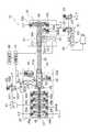
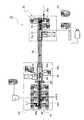
図1は本発明の実施形態に係る塗料供給装置の全体構成を示すブロック図、図2は同実施形態に係る塗料供給装置の受け側ピグステーションを示す断面図、図3A及ぶ図3Bは本実施形態に係るピグを示す側面図及び正面図、図4は本実施形態に係る塗料供給装置の送り側ピグステーションを示す断面図、図5は本実施形態に係る塗装システムを示す概略平面図である。 FIG. 1 is a block diagram showing the overall configuration of a paint supply apparatus according to an embodiment of the present invention, FIG. 2 is a cross-sectional view showing a receiving pig station of the paint supply apparatus according to the embodiment, and FIGS. FIG. 4 is a cross-sectional view showing a feed-side pig station of a paint supply apparatus according to the present embodiment, and FIG. 5 is a schematic plan view showing a coating system according to the present embodiment. .
図1に示すように、本発明の実施形態に係る塗料供給装置10は、例えば回転霧化式静電塗装機やエアー霧化式静電塗装機から構成される塗装ガン2に供給する塗料を、多種類の塗料の中から選択するためのメインカラーチェンジバルブユニット20(以下、メインCCV20と称する。)を有し、メインCCV20から供給された塗料が塗装ガン2へ導かれる。 As shown in FIG. 1, the coating
メインCCV20は、マニホールド21並びに第1三方弁22および図示しない切替弁から構成されており、第1三方弁22の第1ポート221がマニホールド21に接続されている。三方弁22の第2ポート222は、塗料が供給されるように受け側ピグステーション30(後述)に接続され、また、三方弁22の第3ポート223は、圧力を開放したり廃液したりするための第1ダンプ弁23に接続されている。 The
このメインCCV20では、第1三方弁22及び図示しない切替弁の中から何れか一つを選択することで、マニホールド21内にその塗料が供給され、さらに塗装ガン2においてトリガバルブ(不図示)を開放することで、その塗料が被塗物に対して吐出される。なお、第1三方弁22及び切替弁は、図示しない制御装置からの制御信号(エアー信号)に基づいて開閉動作する。In the
ちなみに、図1では、本例の第1三方弁22のみを示し、他の切替弁は省略しているが、この切替弁は、本例の第1三方弁22と同じように構成しても良く、或いは塗料タンクからメイン供給配管を直接接続しても良い。以下の説明においては、便宜的に図示した第1三方弁22を代表して本発明を説明する。 Incidentally, in FIG. 1, only the first three-
図1に示すように、第1三方弁22は、第1センサベース32に形成された通路32aに第2ポート222が連通するように、塗料ホースを介して受け側ピグステーション30に接続されている。第1センサベース32は、図2に示すように、受け側ピグステーション30のステーション本体31に固定されており、第1センサベース32の通路32aが、ステーション本体31の内部に形成された第1副通路31bに連通している。第1センサベース32には、感圧面33aが通路32a内に臨むように、第1圧力センサ33が固定されている。 As shown in FIG. 1, the first three-
図1に示すように、第1圧力センサ33は、その検出結果を送信可能なように、ケーブルを介して判断装置70に接続されている。この判断装置70はCPU等を備えており、第1及び第2圧力センサ33,44の検出結果に基づいて、ピグ90の位置を判断する。判断装置70による具体的な判断手法については後述する。 As shown in FIG. 1, the
判断装置70により判断されたピグ90の位置は、モニタ等から構成される報知装置80に表示される。また、ピグ90が所定位置に存在しないような不具合情報等も報知装置80により報知される。 The position of the
図2に示すように、ステーション本体31の第1副通路31bは、当該ステーション本体31内に形成された主通路31aから分岐した通路である。この主通路31aの一方の端部には、ピグ90が往復移動可能に挿入された塗料ホース50の一方の端部が、キャップ31cにより固定されており、塗料ホース50の内孔と、ステーション本体31の主通路31aとが連通している。 As shown in FIG. 2, the first sub passage 31 b of the station
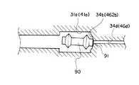
ここで、図3A及び図3Bに示すように、本実施形態に係るピグ90は、両端近傍の2箇所が拡径した略円柱形状とされており、後述するピグステーション30,40のピグ受け面34b,462bに当接して第2副通路34a,462cを封鎖する円柱状の第1シール部91と、塗料ホース50の内壁面に密着する算盤玉状の第2シール部92とを有する。 Here, as shown in FIGS. 3A and 3B, the
第1シール部91は、ピグ90の両端面から構成され、その円形状の縁部がピグ受け面34b,462bにそれぞれ密着することで、第2副通路34a,462cを封鎖する。 The
これに対して第2シール部92は、ピグ90において拡径した部位から構成されている。この第2シール部92の外径D1は、塗料ホース50の内径D2(図2参照)と実質的に同一か僅かに大径とされ(D2≦D1)、ピグ90が塗料ホース50内を移動することで、塗料ホース50内に残留している塗料等を第2シール部92が掻き取るようになっている。なお、第2シール部92の外径D1は、ピグ90が塗料ホース50内を円滑に移動でき、しかも第2シール部92と塗料ホース50の内壁との隙間から塗料が漏れないような寸法とされている。 On the other hand, the
本例のピグ90においては、第1シール部91と第2シール部92とを異なる部位に設けることで各シール部91,92の磨耗が分散され、これによりピグ90の延命化を図ることができる。 In the
図2に示すように、ステーション本体31の主通路31aは、ピグ90の外径D1よりも相対的に大きな内径D3を有しており(D3>D1)、主通路31a内にピグ90を保持したままの状態で、主通路31a内に流体を流通させることが可能となっている。つまり、ピグ90の第2シール部92と主通路31aの内壁との間には流体が円滑に通過できる程度の隙間が形成されている。 As shown in FIG. 2, the main passage 31a of the
図2に示すように、ステーション本体31の他方の端部には、マニホールド34が固定されており、ステーション本体31の主通路31aと、マニホールド34内に形成された第2副通路34aとが連通している。第2副通路34aの内径D4は、主通路31aの内径D3よりも相対的に小さく(D4<D3)、且つ、ピグ90の第1シール部91の外径D7よりも相対的に小さくなっている(D4<D7)。 As shown in FIG. 2, a
また、塗料ホース50を通って受け側ピグステーション30に移動してきたピグ90が当接して停止するためのピグ受け面34bが、マニホールド34におけるステーション本体31側の端面により構成されている。本実施形態では、このピグ受け面34bは、第2副通路34aの開口周囲に形成された凹状の球面形状で構成されている。Further, a
ピグ受け面34bを球面形状とする共に、ピグ90の第1シール部91が円形状の縁部を有することで、ピグ受け面34bに対するピグ90の当接角度に拘らず、第2副通路34aを確実に封鎖することが可能となる。すなわち、球面状の内壁に対して円形の縁部はどのような角度であっても幾何学的に密着する。 Since the
これにより、本実施形態では、配管系内に圧力が正確に変動するため、ピグ90に埋め込んだ磁石を用いた従来のピグ位置検出に代えて、防爆型圧力センサを用いたピグ位置検出が可能となり、塗料供給装置のコストダウンを図るとともに、装置構造を単純にすることができる。As a result, in this embodiment, since the pressure accurately fluctuates in the piping system, it is possible to detect the pig position using an explosion-proof pressure sensor instead of the conventional pig position detection using the magnet embedded in the
図1に戻って、ステーション本体31の他端に固定されたマニホールド34には、洗浄液を供給可能な第1洗浄液供給用バルブ35aと、加圧エアーを供給可能な第1エアー供給用バルブ35bと、外部に廃液するための第2ダンプ弁35cとが設けられている。それぞれの弁35a〜35cは、図示しない制御装置からの制御信号(エアー信号)により開閉動作することが可能となっている。 Returning to FIG. 1, the manifold 34 fixed to the other end of the station
一方、図1および図4に示すように、塗料ホース50の他方の端部には、送り側ピグステーション40のステーション本体41の一方の端部が、キャップ41dにより固定され、塗料ホース50の内孔とステーション本体41内に形成された主通路41aとが連通している。主通路41aは、ピグ90の外径D1よりも相対的に大きな内径D5を有しており(D5>D1)、主通路41a内にピグ90を保持したままの状態で、主通路41a内に流体を流通させることが可能となっている。 On the other hand, as shown in FIGS. 1 and 4, one end of the station
図4に示すように、ステーション本体41には第2センサベース43が固定され、第2センサベース43内に形成された通路43aが主通路41aから分岐した第1副通路41bに連通している。第2センサベース43には、感圧面44aが通路43a内に臨むように、第2圧力センサ44が固定されている。この第2圧力センサ44は、既述した第1圧力センサ33と同様に、検出結果を送信可能なように、ケーブルを介して判断装置70に接続されている。また、図1に示すように、第2センサベース43の通路43aには、外部に廃液するための第3ダンプ弁45が接続されている。 As shown in FIG. 4, a
図4に戻り、本実施形態では、ステーション本体41に、例えばエアーシリンダ等から構成されるストッパ42が固定され、ステーション本体41の側面に形成された貫通孔41cを介して、ストッパピン42aが主通路41a内に進退移動させることが可能となっている。このストッパピン42aが主通路41a内に進出するとピグ90の移動が遮られる一方で、ストッパピン42aが主通路41aから退出すると、ピグ90の移動が可能となる。 Returning to FIG. 4, in the present embodiment, a
また、ステーション本体41の他方の端部には、ピグ90を送り側ピグステーション40内から取り出すための着脱部46が固定されている。この着脱部46は、同図に示すように、ステーション本体41に固定された第1着脱部材461と、サブカラーチェンジバルブユニット47(以下、サブCCV47と称する。)の端部に固定された第2着脱部材462と、これら第1着脱部材461と第2着脱部材462とを連結するためのクランプ463とから構成されている。 An attachment /
第1着脱部材461は、フランジ部461aを有する円盤形状とされ、ステーション本体41の主通路41aと同一の内径D5を有する通路461bがその中心に形成されている。この第1着脱部材46aは、主通路41aと通路461bとが連通するように、ステーション本体41に固定されている。 The first
同様に、第2着脱部材462もフランジ部462aを有する円盤形状とされ、その中心に第2副通路462cが形成されている。この第2副通路462cの内径D6は、主通路41aの内径D5よりも相対的に小さく(D6<D5)、且つ、ピグ90の第1シール部91の外径D7よりも相対的に小さくなっている(D6<D7)。 Similarly, the second
また、塗料ホース50を通って送り側ピグステーション40に移動してきたピグ90が当接して停止するためのピグ受け面462bが、第2着脱部材462において第1着脱部材461と対向する端面により構成されている。本実施形態では、このピグ受け面462bは、上述したピグ受け面34bと同様に、第2副通路462cの開口周囲に形成された凹状の球面形状で構成されている。In addition, the
ピグ受け面462bを球面形状とする共に、ピグ90の第1シール部91が円形状の縁部を有することで、ピグ受け面462bに対するピグ90の当接角度に拘らず、第2副通路462cを確実に封鎖することが可能となる。すなわち、球面状の内壁に対して円形の縁部はどのような角度であっても幾何学的に密着する。 Since the
これにより、本実施形態では、配管系内に圧力が正確に変動するため、ピグに埋め込んだ磁石を用いた従来のピグ位置検出に代えて、防爆型圧力センサを用いたピグ位置検出が可能となり、塗料供給装置のコストダウンを図るとともに、装置構造を単純にすることができる。As a result, in this embodiment, since the pressure accurately fluctuates in the piping system, it is possible to detect the pig position using an explosion-proof pressure sensor instead of the conventional pig position detection using the magnet embedded in the pig. In addition, the cost of the paint supply device can be reduced, and the device structure can be simplified.
第1着脱部材461と第2着脱部材462とは、第2着脱部材462の位置決めピン462dを第1着脱部材461の位置決め穴461cに挿入して、相互に密着させた状態でそれぞれのフランジ部461a,462aをクランプ463で挟み込むことで、ワンタッチ操作で着脱自在に連結される。なお、このように連結された状態において、第1着脱部材461の通路461bと、第2着脱部材462の第2副通路462bとが連通し、第1着脱部材461の通路461bの終点に、第2着脱部材462に形成されたピグ受け面462bが位置している。 The first attaching / detaching
図1に戻り、サブCCV47は、着脱部46に固定されたマニホールド48と、塗料タンク61から塗料が供給される第1〜第5の切替バルブ49a〜49eとを備えており、何れか一つの切替バルブ49a〜49eを選択することで、マニホールド48内に形成された通路48aにその塗料が供給されるようになっている。さらに、この通路48aは、図4に示すように、着脱部46の第2副通路462cに連通し、サブCCV47から着脱部46を介して主通路41aに塗料が供給される。 Returning to FIG. 1, the sub-CCV 47 includes a manifold 48 fixed to the
このサブCCV47は、図1に示すように、洗浄液を供給可能な第2洗浄液供給用バルブ49fと、加圧エアーを供給可能な第2エアー供給用バルブ49gと、外部に廃液するための第4ダンプ弁49hとをさらに備えている。それぞれの弁49a〜49hは、図示しない制御装置からの制御信号(エアー信号)により開閉動作する。 As shown in FIG. 1, the sub-CCV 47 includes a second cleaning
第1〜第5の切替バルブ49a〜49eに供給される塗料Pは、密閉された塗料タンク61内にそれぞれ収容され、塗料タンク61には第2三方弁62の第1ポート621が接続されている。また、第2三方弁62の第2ポート622には加圧エアー源からの加圧エアーが供給される。なお、図示を省略した加圧エアー源からのエアー配管には開閉バルブが設けられ、塗料回収の際には加圧エアー源からの加圧エアーの供給を停止する。 The paint P supplied to the first to
さらに、第2三方弁62の第3ポート623を介して塗料タンク61内の加圧エアーを大気開放することが可能となっている。Furthermore, the pressurized air in the
この第3ポート623を閉じることで、第2ポート622から加圧エアーが密閉された塗料タンク61に供給され、塗料配管63を介して第1切替バルブ49aに向かって塗料Pが圧送される。By closing the
これに対し、第3ポート623を開放するとともに加圧エアー源からの加圧エアーの供給を停止することで、それまで加圧されていた塗料タンク61内の加圧エアーが大気開放され、塗料ホース50から塗料タンク61に向かって塗料を回収することが可能な状態となる。On the other hand, by opening the
なお、図1には、第1切替バルブ49aのみに塗料タンク61及び第2三方弁62が接続されているが、実際には、第2〜第5切替バルブ49b~49eにもそれぞれ別の塗料Pnが収容された塗料タンク61n及び第2三方弁62nが接続されている。In FIG. 1, the
また、本発明では特に限定されないが、塗料タンク61へ送られる加圧エアーは、一般的な加圧力5kg/cm2よりも低圧である、たとえば数kg/cm2の塗装仕様にも適用することができる。Moreover, it is not particularly limited in the present invention, pressurized air is sent into the
以上のような構成の塗料供給装置10は、図5に示すように、例えば塗装ブースB内に設けられた複数の塗装ロボット4に対して1台ずつ設けられて塗装システムを構成する。塗装ロボット4の先端には、エンドエフェクタとして塗装ガン2が設けられており、塗料供給装置10からこの塗装ガン2に各色の塗料を供給することが可能となっている。 As shown in FIG. 5, the coating
なお、本発明においては上記のような塗装システムに限定されず、例えば、複数の塗装ロボット4に対して1台の塗料供給装置10を割り当てても良い。 In the present invention, the present invention is not limited to the coating system as described above. For example, one
次に、本実施形態に係る塗料回収方法を、塗料供給装置10の色替え手順に従って説明する。 Next, the paint recovery method according to the present embodiment will be described according to the color change procedure of the
図6は本実施形態に係る塗料回収方法を示すフローチャート、図7A〜図7Fは図6に示す各ステップにおける塗料供給装置の状態を示すブロック図、図8A及び図8Bはピグステーション内においてピグが受け面に当接した状態を示す図、図9は塗料回収時における押出用流体の層構造を示す断面図である。 FIG. 6 is a flowchart showing the paint recovery method according to the present embodiment, FIGS. 7A to 7F are block diagrams showing the state of the paint supply device in each step shown in FIG. 6, and FIGS. FIG. 9 is a cross-sectional view showing a layer structure of an extruding fluid during paint recovery.
まず、図7Aに示すように、塗料供給装置10が前色の塗料(塗料タンク61に収容されている塗料P)を塗装ガン2に供給している状態(図6のステップS10)について説明する。なお、初期状態では、ピグ90が送り側ピグステーション40内に位置し、ストッパ42のストッパピン42aを主通路41aから退出させ、さらに全ての弁を閉じた状態となっている。 First, as shown in FIG. 7A, a state (step S10 in FIG. 6) in which the
このような状態では、第2三方弁62の第3ポート623は閉じられているので、第2三方弁62の第2ポート622を介して塗料タンク61内に加圧エアーが導入され、塗料タンク61内が加圧される。この密閉された塗料タンク61内の加圧力が塗料の吐出圧となる。In such a state, since the
ここで、サブCCV47の第1切替バルブ49aを開くと共に、第2ダンプ弁35cを開くと、塗料タンク61内の塗料Pが、マニホールド48の通路48a→第2着脱部材462の第2副通路462c→第1着脱部材461の通路461b→ステーション本体41の主通路41a→塗料ホース50を経由して、受け側ピグステーション30に至る。この間、ピグ90は、送り側ピグステーション40から受け側ピグステーション30に塗料ホース50を介して圧送(背面から塗料Pで押圧)され、受け側ピグステーション30のピグ受け面34bに当接することで停止する。なお、ステップS10にて第2ダンプ弁35cを開くのは、塗料Pが流通する通路を大気開放させることで、低圧であっても塗料を円滑に圧送させるためである。Here, when the
このピグ90の第1シール部91とピグ受け面34bとの当接により、図8Aに示すように、第2副通路34aが封鎖され、第2ダンプ弁35cへの流路が自動的に遮断される。なお、本実施形態では、ピグ受け面34bが球面形状となっている共に、ピグ90の第1シール部91が円形状の縁部を有しているので、図8Bに示すように、ピグ受け面34bに対してピグ90が斜めに当接しても、第2副通路34aを確実に封鎖することができる。By contact between the
この際、判断装置70は、第1圧力センサ33により検出された圧力P1と、第2圧力センサ44により検出された圧力P2とを比較する。これらの圧力P1,P2が実質的に同一である場合(P1=P2)には、判断装置70は、ピグ90が受け側ピグステーション30に移動したものと判断する。 At this time, the determination device 70 compares the pressure P1 detected by the
これに対し、圧力P1,P2が同一でない状態(P1≠P2)で所定時間が経過した場合には、判断装置70は、ピグ90が受け側ピグステーション30に移動していないものと判断し、報知装置80はその不具合情報を報知する。 On the other hand, when the predetermined time has passed in a state where the pressures P1 and P2 are not the same (P1 ≠ P2), the determination device 70 determines that the
これは以下の理由による。すなわち、ピグ90が塗料タンク61から押し出された塗料Pに押された状態で、送り側ピグステーション40から受け側ピグステーション30へ向かって塗料ホース50を移動中は、第2圧力センサ44により検出される圧力P2が塗料圧となる一方で、第1圧力センサ33により検出される圧力P1は大気圧となるので、塗料圧(つまり加圧エアーの圧力)を数kg/cm2にしておけば、正常にピグ90が移動している限りP1<P2となる。また、ピグ90が正常に受け側ピグステーション30に到着すると、第2圧力センサ44により検出される圧力P2が塗料圧を維持する一方で、第1圧力センサ33により検出される圧力P1も塗料圧となるのでP1=P2となる。This is due to the following reason. That is, the
このようにしてピグ90が受け側ピグステーション30に移動したことを検出すると、第1ダンプ弁23を所定時間だけ大気開放する。この大気開放により、ステーション本体31の主通路31aに至った塗料Pは、第1センサベース32内の通路32a→塗料ホース→メインCCV20の第1三方弁22の第2ポート222に至り、塗料Pが第1三方弁22内に充填され、塗装準備が完了する。そして、塗料タンク61内に収容された塗料Pを塗装するタイミングになると第1三方弁22が開かれて、塗装ガン2に塗料が供給される。 When it is detected that the
塗装作業が終了し、異なる塗料を塗装する場合には、以下の手順に従って塗料供給装置10の色替操作を行う。 When the painting operation is completed and a different paint is applied, the color changing operation of the
まず、図6のステップS20に示すように、これまで塗装を行っていた塗料を塗料タンク61へ回収する。前色塗料の塗装完了を示す信号に基づいて、第2ダンプ弁35cを閉じると共に、第2三方弁62の第3ポート622を大気開放し(同時に加圧エアーの供給も停止する。)、塗料タンク61内の加圧を解除する。 First, as shown in step S <b> 20 of FIG. 6, the paint that has been applied is collected in the
そして、受け側ピグステーション30の第1洗浄液供給用バルブ35a又は第1エアー供給用バルブ35bを開いて、洗浄液又は加圧エアーを供給して、受け側ピグステーション30内に位置していたピグ90を送り側ピグステーション40に押し戻し、塗料ホース50内に充填されていた塗料を塗料タンク61へ回収する。Then, the first cleaning
このときピグ90は、送り側ピグステーション40のピグ受け面462bに当接することで停止する。このピグ90の第1シール部91とピグ受け面462bとの当接により、第2副通路462cが封鎖され、サブCCV47への流路が自動的に遮断される。At this time, the
この際、判断装置は、第1圧力センサ33により検出された圧力P1と、第2圧力センサ44により検出された圧力P2とを比較する。これらの圧力P1,P2が実質的に同一である場合(P1=P2)には、判断装置70は、ピグ90が送り側ピグステーション40に移動したものと判断し、例えば、報知装置80がモニタ等にピグ90の位置を表示する。 At this time, the determination device compares the pressure P1 detected by the
これに対し、圧力P1,P2が同一でない状態(P1≠P2)で所定時間が経過した場合には、判断装置70は、ピグ90が送り側ピグステーション40に移動していないものと判断し、報知装置80は、モニタ等を介してその不具合情報を報知する。 On the other hand, when the predetermined time has passed in the state where the pressures P1 and P2 are not the same (P1 ≠ P2), the determination device 70 determines that the
これは以下の理由による。すなわち、ピグ90が洗浄液または加圧エアーに押された状態で、受け側ピグステーション30から送り側ピグステーション40へ向かって塗料ホース50を移動中は、第1圧力センサ33により検出される圧力P1は洗浄液または加圧エアーの圧力となる一方で、第2圧力センサ44により検出される圧力P2は残留塗料の圧力、すなわち大気圧となるので、洗浄液または加圧エアーの圧力を大気圧以上にしておけば、正常にピグ90が移動している限りP1>P2となる。また、ピグ90が正常に送り側ピグステーション40に到着すると、第1圧力センサ33により検出される圧力P1は洗浄液または加圧エアー圧を維持する一方で、第2圧力センサ44により検出される圧力P2も洗浄液または加圧エアー圧となるのでP1=P2となる。This is due to the following reason. That is, the pressure P1 detected by the
なお、第1洗浄液供給用バルブ35aを介して供給される洗浄液としては、塗料が有機溶剤系塗料である場合にはシンナーを用いることができ、塗料が水系塗料である場合には水を用いることができる。 As the cleaning liquid supplied through the first cleaning
また、上述の実施形態では、ピグ90を介して塗料Pを押し戻すに当たり、第1洗浄液供給用バルブ35a又は第1エアー供給用バルブ35bから供給される洗浄液又はエアーを押出用流体として利用するように説明したが、本発明においては特に限定されず、以下のような押出用流体100を用いても良い。 In the above-described embodiment, when the paint P is pushed back through the
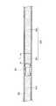
例えば、図9に示すように、ピグ90を介して塗料ホース50内に充填されている塗料Pを塗料タンク61へ押し戻す(回収する)ための押出用流体100は、空気から構成される第1の層101と、溶剤から構成される第2の層102と、から構成されており、第2の層102とピグ90との間に第1の層101が介在している。第1エアー供給用バルブ35bから加圧エアーを供給して第1の層101を形成し、次いで、第1洗浄液供給用バルブ35aから洗浄液を供給して第2の層102を形成することで、この押出用流体100を構成することができる。塗料ホース50内における第1の層101の軸方向に沿った長さLは、塗料ホース50の内径や長さに応じて、10〜30mm程度であることが好ましい。なお、第1の層101を、塗料に含まれる溶剤や希釈溶剤で構成しても良い。 For example, as shown in FIG. 9, the
押出用流体100の第1の層101により、塗料に洗浄液が混入するのを防止して、塗料の品質の安定化を図ることができる。また、押出用流体100の第2の層102により、塗料回収時の押出用流体100の圧縮量を小さくすることができ、安定して装置を稼動させることができる。 The
ピグ90が送り側ピグステーション40に移動したことを検出したら、図7Bに示すように、第3ダンプ弁45を開くと共に、第1洗浄液供給用バルブ35aを開いて洗浄液を供給する(図6のステップS30)。これにより、マニホールド34内の第2副通路34a→ステーション本体31内の主通路31a→塗料ホース50→ステーション本体41内の主通路41a→第2センサベース43内の通路43aに至る経路が洗浄される。 When it is detected that the
また、このステップS30の際、ステーション本体41の主通路31a内にピグ90が保持されたままの状態となっているので、ピグ90において主として受け側ピグステーション30側の先端部(同図の右側)が洗浄される。また、第2センサベース43の通路43a内も洗浄液が通過するので、第2圧力センサ44の感圧面44aが洗浄される。 In addition, since the
次に、図7Cに示すように、ストッパ42を作動させて、ストッパピン42aを主通路41a内に進出させると共に、第1洗浄液供給用バルブ35aを閉じ、この状態で、第2洗浄液供給用バルブ49fを開いて洗浄液を供給する(図6のステップS40)。これにより、サブCCV47のマニホールド48の通路48a→第2着脱部材462の第2副通路462c→第1着脱部材461の通路461b→ステーション本体41の主通路41a→第2センサベース43の通路43aに至る経路が、洗浄液により洗浄される。また、このステップS40の際、受け側ピグステーション30側へのピグ90の移動がストッパ42により規制されているので、主としてピグ90の後端部(同図の左側)が洗浄される。 Next, as shown in FIG. 7C, the
なお、第2洗浄液供給用バルブ49fを介して供給される洗浄液としては、塗料が有機溶剤系塗料である場合にはシンナーを用いることができ、塗料が水系塗料である場合には水を用いることができる。 As the cleaning liquid supplied through the second cleaning
次に、図7Dに示すように、第3ダンプ弁45を閉じると共に、第1ダンプ弁23を開き、この状態で、第2洗浄液供給用バルブ49fを開いて洗浄液を供給する(図6のステップS50)。これにより、サブCCV47のマニホールド48の通路48a→第2着脱部材462の第2副通路462c→第1着脱部材461の通路461b→ステーション本体41の主通路41a→塗料ホース50→ステーション本体31の主通路31a→第1センサベース33の通路33a→第1三方弁22に至る流路が洗浄液により洗浄される。 Next, as shown in FIG. 7D, the
この際、ピグ90は、ストッパ42により送り側ピグステーション40の主通路41a内に保持されていると共に、その外径D1が主通路41aの内径D5よりも相対的に小さくなっており、ピグ90の周囲を洗浄液が通過するため、ピグ90の洗浄がより確実なものとなる。 At this time, the
次に、図7Eに示すように、第1ダンプ弁23を閉じると共に、第2ダンプ弁35cを開き、この状態で、第2洗浄液供給用バルブ49fを開いて洗浄液を供給する(図6のステップS60)。これにより、サブCCV47のマニホールド48の通路48a→第2着脱部材462の第2副通路462c→第1着脱部材461の通路461b→ステーション本体41の主通路41a→塗料ホース50→ステーション本体31の主通路31a→マニホールド34の第2副通路34aに至る経路が洗浄液により洗浄される。 Next, as shown in FIG. 7E, the
次に、図7Fに示すように、第2ダンプ弁35c、第2洗浄液供給用バルブ49fを閉じると共に、第4ダンプ弁49h及び第1エアー供給用バルブ35bを開いてエアーを供給する(図6のステップS70)。これにより、流路内に残留していた洗浄液が第4ダンプ弁49hから廃棄されると同時に、ストッパ42により規制されているピグ90が、送り側ピグステーション40のピグ受け面462bに向かって移動する。次いで、第4ダンプ弁49h及び第1のエアー供給用バルブ35bを閉じると共に、ストッパピン42aを主通路41aから退出させることで、塗料供給装置10が初期状態に復帰したこととなる。 Next, as shown in FIG. 7F, the
以上のステップS20〜S70までの作業を経ることで色替作業が完了し、塗料供給装置10に次色の塗料を充填することが可能な状態となる。 The color change operation is completed through the above steps S20 to S70, and the
以上のように本実施形態では、受け側ピグステーション30においては、ピグ90がピグ受け面34bに当接することで、塗装ガン2につながっていない第2副通路34aを封鎖し、ピグ90を主通路31a内に保持したままの状態で、ピグ90に封鎖されていない第1副通路31bを使って塗装ガン2に塗料を供給することができる。 As described above, in the present embodiment, in the receiving-
また、送り側ピグステーション40においては、ピグ90がピグ受け面462bに当接することで、塗料タンク61につながっている第2副通路462cをピグ90により封鎖し、そのピグ90を主通路41a内に保持したままの状態で、ピグ90に封鎖されていない第1副通路41bを使って塗料ホース50内を洗浄することができる。 Further, in the feeding-
従って、塗料ホース50やピグステーション30,40の洗浄時や塗料供給時にピグ90を塗料ホース50やピグステーション30,40から退避させるための専用の配管を必要とせず、塗料供給装置10の小型化を図ると共に、色替えに要する時間の短縮化を図ることができる。 Therefore, there is no need for a dedicated pipe for retracting the
なお、以上説明した実施形態は、本発明の理解を容易にするために記載されたものであって、本発明を限定するために記載されたものではない。したがって、上記の実施形態に開示された各要素は、本発明の技術的範囲に属する全ての設計変更や均等物をも含む趣旨である。 The embodiment described above is described for facilitating the understanding of the present invention, and is not described for limiting the present invention. Therefore, each element disclosed in the above embodiment is intended to include all design changes and equivalents belonging to the technical scope of the present invention.
例えば、上述の実施形態では、送り側ピグステーション40内にピグ90を保持した状態でそのピグ90を洗浄するように説明したが、本発明においては特にこれに限定されず、受け側ピグステーション30にピグ90の移動を規制するストッパを設けて、受け側ピグステーション30内にピグ90を保持した状態でそのピグ90を洗浄しても良い。 For example, in the above-described embodiment, the
10…塗料回収装置
20…メインCCV
30…受け側ピグステーション
31…ステーション本体
31a…主通路
31b…第1副通路
32…第1センサベース
33…第1圧力センサ
34…マニホールド
34a…第2副通路
34b…ピグ受け面
40…送り側ピグステーション
41…ステーション本体
41a…主通路
41b…第1副通路
42…ストッパ
43…第2センサベース
44…第2圧力センサ
46…着脱部
462b…ピグ受け面
462c…第2副通路
47…サブCCV
50…塗料ホース
61…塗料タンク
62…第2三方弁
90…ピグ10 ...
DESCRIPTION OF
50 ...
Claims (9)
Translated fromJapanese前記塗料配管の端部にそれぞれ接続された第1及び第2ピグ発着部とを備え、
前記第1ピグ発着部側から押出用流体を供給して前記塗料配管を介して前記第2ピグ発着部に前記ピグを移動させることで、前記塗料配管内に残留した塗料を回収することが可能な塗料供給装置であって、
前記第1又は第2ピグ発着部のうちの少なくとも一方は、前記塗料配管が接続され、前記ピグが進入可能な主通路と、前記ピグの移動を阻止するピグ受け面と、 前記主通路に連通した少なくとも2つの副通路とを有し、
前記ピグが前記ピグ受け面に当接することで、前記少なくとも2つの副通路のうちの一つを前記ピグが封鎖する塗料供給装置において、
塗料が収容されて密閉空間とされ、前記塗料配管へ塗料を供給する塗料タンクと、
前記塗料タンクの密閉された空間に接続されて加圧エアーを供給する加圧エアー源と、
前記加圧エアー源と前記塗料タンクの密閉空間とを接続するエアー配管と、
前記エアー配管の途中に設けられ、第1ポジションにおいて前記加圧エアー源から供給される加圧エアーを前記塗料タンクの密閉空間へ供給するとともに、第2ポジションにおいて前記塗料タンクの密閉空間の圧力を減圧する三方弁とを有することを特徴とする塗料供給装置。A paint pipe inserted so that the pig can reciprocate along the axial direction;
First and second pig landing parts connected to the ends of the paint pipe,
It is possible to recover the paint remaining in the paint pipe by supplying the extrusion fluid from the first pig feed / deposit part side and moving the pig to the second pig launch / deposit part via the paint pipe A paint supply device,
At least one of the first and second pig landing portions is connected to the paint pipe, a main passage through which the pig can enter, a pig receiving surface that prevents movement of the pig, and communication with the main passage And at least two secondary passages,
In the paint supply apparatus in which the pig seals one of the at least two sub-passages by the pig coming into contact with the pig receiving surface,
A paint tank that contains paint and is a sealed space, and supplies the paint to the paint pipe;
A pressurized air source connected to the sealed space of the paint tank to supply pressurized air;
An air pipe connecting the pressurized air source and the sealed space of the paint tank;
In the first position, the pressurized air supplied from the pressurized air source is supplied to the sealed space of the paint tank, and the pressure of the sealed space of the paint tank is set in the second position. A paint supply device comprising a three-way valve for decompressing.
前記ピグにおいて前記ピグ受け面に当接する当接部は、円形状の縁部を有することを特徴とする請求項1〜3の何れかに記載の塗料供給装置。The pig receiving surface is formed in a spherical shape around the opening of the sub-passage sealed by the pig,
The paint supply device according to claim 1, wherein a contact portion that contacts the pig receiving surface of the pig has a circular edge.
前記第1シール部と前記第2シール部とは、前記ピグにおいてそれぞれ異なる部位に設けられていることを特徴とする請求項1〜4の何れかに記載の塗料供給装置。The pig has a first seal portion that contacts the pig receiving surface and seals the sub-passage, and a second seal portion that comes into close contact with the inner wall surface of the paint pipe,
The paint supply apparatus according to any one of claims 1 to 4, wherein the first seal part and the second seal part are provided in different parts of the pig.
前記塗料配管内において、前記ピグと前記第2の層との間に前記第1の層が介在していることを特徴とする請求項1〜5の何れかに記載の塗料供給装置。The extrusion fluid has a first layer composed of air or a solvent, and a second layer composed of a cleaning liquid for cleaning the inside of the paint pipe,
The paint supply apparatus according to claim 1, wherein the first layer is interposed between the pig and the second layer in the paint pipe.
前記検出手段の検出結果に基づいて、前記ピグが前記第1又は第2ピグ発着部内に位置しているか否かを判断する判断手段と、をさらに備えたことを特徴とする請求項1〜6の何れかに記載の塗料供給装置。Detecting means for detecting a pressure in the main passage of at least one of the first or second pig landing parts;
7. A judgment means for judging whether or not the pig is located in the first or second pig landing part based on a detection result of the detection means. The coating material supply apparatus in any one of.
前記第1ピグ発着部の主通路内の圧力と、前記第2ピグ発着部の主通路内の圧力とが実質的に同一である場合に、前記第1又は第2ピグ発着部内に前記ピグが位置していると判断することを特徴とする請求項8記載の塗料供給装置。When the pressure in the main passage of the first pig landing part is different from the pressure in the main passage of the second pig landing part, the determination means is that the pig is located in the paint pipe Judgment
When the pressure in the main passage of the first pig landing part and the pressure in the main passage of the second pig landing part are substantially the same, the pig is in the first or second pig landing part. The paint supply apparatus according to claim 8, wherein the paint supply apparatus is determined to be positioned.
Priority Applications (1)
| Application Number | Priority Date | Filing Date | Title |
|---|---|---|---|
| JP2007052295AJP5040365B2 (en) | 2007-03-02 | 2007-03-02 | Paint supply device |
Applications Claiming Priority (1)
| Application Number | Priority Date | Filing Date | Title |
|---|---|---|---|
| JP2007052295AJP5040365B2 (en) | 2007-03-02 | 2007-03-02 | Paint supply device |
Publications (2)
| Publication Number | Publication Date |
|---|---|
| JP2008212801A JP2008212801A (en) | 2008-09-18 |
| JP5040365B2true JP5040365B2 (en) | 2012-10-03 |
Family
ID=39833490
Family Applications (1)
| Application Number | Title | Priority Date | Filing Date |
|---|---|---|---|
| JP2007052295AExpired - Fee RelatedJP5040365B2 (en) | 2007-03-02 | 2007-03-02 | Paint supply device |
Country Status (1)
| Country | Link |
|---|---|
| JP (1) | JP5040365B2 (en) |
Family Cites Families (7)
| Publication number | Priority date | Publication date | Assignee | Title |
|---|---|---|---|---|
| JP3111902B2 (en)* | 1996-06-11 | 2000-11-27 | 三菱自動車工業株式会社 | Paint supply device |
| DE19728155A1 (en)* | 1997-07-03 | 1999-01-07 | Lactec Gmbh | Cleaning and preparation method for paint spray pipe |
| JP3876723B2 (en)* | 2002-02-13 | 2007-02-07 | 日産自動車株式会社 | Paint supply device |
| JP2006192407A (en)* | 2005-01-17 | 2006-07-27 | Nissan Motor Co Ltd | Pig position detection apparatus and method |
| JP4720237B2 (en)* | 2005-03-22 | 2011-07-13 | 日産自動車株式会社 | Paint supply apparatus and method |
| JP4235631B2 (en)* | 2005-08-30 | 2009-03-11 | デュル・ジャパン株式会社 | Painting equipment |
| JP4945970B2 (en)* | 2005-09-07 | 2012-06-06 | 日産自動車株式会社 | Paint supply device and coating system provided with the same |
- 2007
- 2007-03-02JPJP2007052295Apatent/JP5040365B2/ennot_activeExpired - Fee Related
Also Published As
| Publication number | Publication date |
|---|---|
| JP2008212801A (en) | 2008-09-18 |
Similar Documents
| Publication | Publication Date | Title |
|---|---|---|
| JP5507571B2 (en) | Improved double block and fluid discharge plug | |
| US20190333420A1 (en) | Quick connect fluid connector with tube variation tolerance and connection verification | |
| US8201585B2 (en) | Method and apparatus for filling coating material | |
| US20090267346A1 (en) | Socket for fluid-transfer coupling device | |
| US20090272450A1 (en) | Plug for fluid-transfer coupling device | |
| KR101849618B1 (en) | Trenchless sewer pipe reparing apparatus and method there of | |
| JP2006029457A (en) | Paint selector valve | |
| US11692657B2 (en) | Quick connect fluid connector, swivel, and combination thereof | |
| US9126220B2 (en) | Paint material switching path and colour changer | |
| US10480701B2 (en) | Pipeline insertion apparatus and method | |
| JP5040365B2 (en) | Paint supply device | |
| JP4992470B2 (en) | Paint supply device and method for determining replacement time of pigs worn in paint supply device | |
| BRPI0619116A2 (en) | ink supply system | |
| US11987488B2 (en) | Module connector, module container, and sealing element therefor | |
| JP4998013B2 (en) | Paint supply device | |
| CN111577902A (en) | Valve body assembly | |
| JP4992469B2 (en) | Paint supply device and paint recovery method | |
| JP5003207B2 (en) | Mounting member | |
| JP5140970B2 (en) | Pig position detection device and pig position detection method | |
| KR102111062B1 (en) | Container for receiving puncture repair fluid | |
| JP4614654B2 (en) | Coupler | |
| KR102115017B1 (en) | Sealing device for check device and sealing system of brake hose check apparatus equipped with the coupler module | |
| JP2025084981A (en) | Valves and Systems | |
| TWI685613B (en) | A pump, a coating apparatus | |
| JPH11589A (en) | Paint feeding control system |
Legal Events
| Date | Code | Title | Description |
|---|---|---|---|
| A621 | Written request for application examination | Free format text:JAPANESE INTERMEDIATE CODE: A621 Effective date:20100126 | |
| A977 | Report on retrieval | Free format text:JAPANESE INTERMEDIATE CODE: A971007 Effective date:20120113 | |
| A131 | Notification of reasons for refusal | Free format text:JAPANESE INTERMEDIATE CODE: A131 Effective date:20120124 | |
| A521 | Written amendment | Free format text:JAPANESE INTERMEDIATE CODE: A523 Effective date:20120326 | |
| A131 | Notification of reasons for refusal | Free format text:JAPANESE INTERMEDIATE CODE: A131 Effective date:20120417 | |
| A521 | Written amendment | Free format text:JAPANESE INTERMEDIATE CODE: A523 Effective date:20120521 | |
| TRDD | Decision of grant or rejection written | ||
| A01 | Written decision to grant a patent or to grant a registration (utility model) | Free format text:JAPANESE INTERMEDIATE CODE: A01 Effective date:20120612 | |
| A01 | Written decision to grant a patent or to grant a registration (utility model) | Free format text:JAPANESE INTERMEDIATE CODE: A01 | |
| A61 | First payment of annual fees (during grant procedure) | Free format text:JAPANESE INTERMEDIATE CODE: A61 Effective date:20120625 | |
| R150 | Certificate of patent or registration of utility model | Free format text:JAPANESE INTERMEDIATE CODE: R150 | |
| FPAY | Renewal fee payment (event date is renewal date of database) | Free format text:PAYMENT UNTIL: 20150720 Year of fee payment:3 | |
| LAPS | Cancellation because of no payment of annual fees |