JP5038649B2 - Pneumatic tire - Google Patents
Pneumatic tireDownload PDFInfo
- Publication number
- JP5038649B2 JP5038649B2JP2006115028AJP2006115028AJP5038649B2JP 5038649 B2JP5038649 B2JP 5038649B2JP 2006115028 AJP2006115028 AJP 2006115028AJP 2006115028 AJP2006115028 AJP 2006115028AJP 5038649 B2JP5038649 B2JP 5038649B2
- Authority
- JP
- Japan
- Prior art keywords
- groove
- pneumatic tire
- edge portion
- land
- edge
- Prior art date
- Legal status (The legal status is an assumption and is not a legal conclusion. Google has not performed a legal analysis and makes no representation as to the accuracy of the status listed.)
- Expired - Fee Related
Links
- 230000000694effectsEffects0.000description9
- 230000000052comparative effectEffects0.000description6
- 230000001133accelerationEffects0.000description4
- 238000010586diagramMethods0.000description4
- 238000005452bendingMethods0.000description3
- 230000000994depressogenic effectEffects0.000description1
- 238000011156evaluationMethods0.000description1
- 238000005192partitionMethods0.000description1
- 230000002265preventionEffects0.000description1
- 239000004575stoneSubstances0.000description1
Images


Classifications
- B—PERFORMING OPERATIONS; TRANSPORTING
- B60—VEHICLES IN GENERAL
- B60C—VEHICLE TYRES; TYRE INFLATION; TYRE CHANGING; CONNECTING VALVES TO INFLATABLE ELASTIC BODIES IN GENERAL; DEVICES OR ARRANGEMENTS RELATED TO TYRES
- B60C11/00—Tyre tread bands; Tread patterns; Anti-skid inserts
- B60C11/03—Tread patterns
- B60C11/13—Tread patterns characterised by the groove cross-section, e.g. for buttressing or preventing stone-trapping
- B—PERFORMING OPERATIONS; TRANSPORTING
- B60—VEHICLES IN GENERAL
- B60C—VEHICLE TYRES; TYRE INFLATION; TYRE CHANGING; CONNECTING VALVES TO INFLATABLE ELASTIC BODIES IN GENERAL; DEVICES OR ARRANGEMENTS RELATED TO TYRES
- B60C11/00—Tyre tread bands; Tread patterns; Anti-skid inserts
- B60C11/03—Tread patterns
- B60C11/0302—Tread patterns directional pattern, i.e. with main rolling direction
- B—PERFORMING OPERATIONS; TRANSPORTING
- B60—VEHICLES IN GENERAL
- B60C—VEHICLE TYRES; TYRE INFLATION; TYRE CHANGING; CONNECTING VALVES TO INFLATABLE ELASTIC BODIES IN GENERAL; DEVICES OR ARRANGEMENTS RELATED TO TYRES
- B60C11/00—Tyre tread bands; Tread patterns; Anti-skid inserts
- B60C11/03—Tread patterns
- B60C11/04—Tread patterns in which the raised area of the pattern consists only of continuous circumferential ribs, e.g. zig-zag
- B60C11/042—Tread patterns in which the raised area of the pattern consists only of continuous circumferential ribs, e.g. zig-zag further characterised by the groove cross-section
- B60C11/045—Tread patterns in which the raised area of the pattern consists only of continuous circumferential ribs, e.g. zig-zag further characterised by the groove cross-section the groove walls having a three-dimensional shape
- B—PERFORMING OPERATIONS; TRANSPORTING
- B60—VEHICLES IN GENERAL
- B60C—VEHICLE TYRES; TYRE INFLATION; TYRE CHANGING; CONNECTING VALVES TO INFLATABLE ELASTIC BODIES IN GENERAL; DEVICES OR ARRANGEMENTS RELATED TO TYRES
- B60C11/00—Tyre tread bands; Tread patterns; Anti-skid inserts
- B60C11/03—Tread patterns
- B60C11/12—Tread patterns characterised by the use of narrow slits or incisions, e.g. sipes
Landscapes
- Engineering & Computer Science (AREA)
- Mechanical Engineering (AREA)
- Tires In General (AREA)
Description
Translated fromJapanese本発明は、空気入りタイヤに関し、特にトレッド部における溝の詰まりを抑制するための構造に関する。 The present invention relates to a pneumatic tire, and more particularly to a structure for suppressing clogging of grooves in a tread portion.
スタッドレスタイヤなどの冬用タイヤにおいては、雪道に対する制動性、加速性、旋回性などのスノー性能を向上させることが求められる。そのため、従来、トレッド部におけるブロックやリブの側面をジグザグ状に形成するなどして、該側面に追加的なエッジ部を設け、これにより、トラクション効果が発揮されるように構成することがある(下記特許文献1,2参照)。 Winter tires such as studless tires are required to improve snow performance such as braking performance, acceleration performance, and turning performance on snowy roads. Therefore, conventionally, the side surfaces of the blocks and ribs in the tread portion are formed in a zigzag shape, for example, and an additional edge portion is provided on the side surface, whereby the traction effect is exhibited in some cases. See Patent Documents 1 and 2 below).
このように、ブロックやリブにジグザグ部を設けることにより、一応スノー性能は向上するが、従来のジグザグ形状では、ブロックやリブを区画する溝に雪が詰まりやすく、かかる雪詰まりによりトラクション効果が半減するという問題がある。 As described above, by providing the zigzag portion on the block or rib, the snow performance is improved. However, with the conventional zigzag shape, the groove that partitions the block or rib is likely to be clogged with snow, and the traction effect is halved due to such clogging. There is a problem.
なお、下記特許文献3には、溝の側壁に複数の突起を設ける構成が開示されているが、同文献は、石噛み防止性能の向上を目的としたものであって、本発明とは目的が相違するだけでなく、その構成についても溝の深さ方向に複数の突起を並べて設けるものであって、本発明の特徴を何ら開示するものではない。
従来のジグザグ形状が雪詰まりの生じやすい理由は、次のように考えられる。 The reason why the conventional zigzag shape is likely to cause snow clogging is considered as follows.
図10は、従来のジグザグ形状を適用した比較例に係るブロック形状を示した図である。ブロック100の側面101には、ブロック表面102から溝底部103にかけてエッジ部104が溝内に突出させて設けられており、該エッジ部104が一側面101に2つ設けられることで、該側面101はジグザグ状に形成されている。そして、該エッジ部104は、ブロック表面102から溝底部103にかけて略垂直の直線状に延びている。 FIG. 10 is a diagram showing a block shape according to a comparative example to which a conventional zigzag shape is applied. The
このように各エッジ部104が略垂直に設定されていると、図11に示すように、溝に入ってきた雪は行き場がなく、動きにくい状態となり(雪の動きを矢印で示す。)、溝から雪が排出されにくい。そのため、溝に雪が詰まりやすく、詰まった雪によりトラクション効果が半減して、スノー性能を損なうことになる。 Thus, when each
かかる問題は、雪詰まりによるスノー性能の低下だけでなく、溝に泥が詰まることによるマッド性能の低下についても同様である。 Such a problem is not only caused by a decrease in snow performance due to snow clogging, but also by a reduction in mud performance due to mud clogging in the grooves.
そこで、本発明は、このようなエッジ部を有するトレッド部構成において、溝の詰まりを抑制することでトラクション効果を維持し、これによりスノー性能やマッド性能を向上することができる空気入りタイヤを提供することを目的とする。 Therefore, the present invention provides a pneumatic tire capable of maintaining the traction effect by suppressing clogging of the groove in the tread portion configuration having such an edge portion, thereby improving the snow performance and the mud performance. The purpose is to do.
本発明に係る空気入りタイヤは、トレッド表面に設けた溝によって区画される陸部を備えたトレッド部を有し、前記陸部の側面に陸部表面から溝底部にかけて当該溝内に突出するエッジ部が設けられ、該エッジ部が、前記陸部の側面を正面として見て、前記溝の深さ方向において鈍角状の曲部により階段状に形成されたものである。また、前記エッジ部が前記陸部の側面に複数設けられることで該側面がジクザク状に形成され、前記陸部の側面に対する前記エッジ部の突出幅が、隣接するエッジ部間の配設間隔よりも小さく設定されている。上記曲部は、鈍角に折れ曲がる折曲部(即ち、角張った形状)でもよく、あるいはまた、鈍角状に湾曲する湾曲部(即ち、丸みを帯びた形状)であってもよい。The pneumatic tire according to the present invention has a tread portion including a land portion partitioned by a groove provided on the tread surface, and an edge protruding into the groove from a land surface to a groove bottom on a side surface of the land portion. A portion is provided, and the edge portion is formed in a staircase shape by an obtuse angled curved portion in the depth direction of the groove when the side surface of the land portion is viewed from the front.In addition, a plurality of the edge portions are provided on the side surface of the land portion so that the side surface is formed in a zigzag shape, and the protruding width of the edge portion with respect to the side surface of the land portion is based on an arrangement interval between adjacent edge portions. Is set too small. The bent portion may be a bent portion that is bent at an obtuse angle (ie, an angular shape), or may be a curved portion that is bent at an obtuse angle (ie, a rounded shape).
本発明によれば、ブロックやリブなどのトレッド陸部の側面に陸部表面から溝底部にかけて延びるエッジ部を設けたものにおいて、かかるエッジ部を溝の深さ方向にて鈍角状の曲部により階段状に曲げて形成したので、溝に入ってきた雪や泥が鈍角状の曲部のおかげで動きやすくなる。そのため、走行中に雪や泥を徐々に排出することができて、溝詰まりが抑制される。よって、トラクション効果を維持して、スノー性能やマッド性能を向上することができる。 According to the present invention, an edge portion extending from the land portion surface to the groove bottom portion is provided on the side surface of the tread land portion such as a block or a rib, and the edge portion is obtusely bent in the depth direction of the groove. Because it is formed in a staircase shape, snow and mud that has entered the groove are easy to move thanks to the obtuse corner. Therefore, snow and mud can be gradually discharged during traveling, and clogging of the grooves is suppressed. Therefore, the snow performance and the mud performance can be improved while maintaining the traction effect.
以下、本発明の実施形態について図面を参照して説明する。 Embodiments of the present invention will be described below with reference to the drawings.
(第1実施形態)
図1は、本発明の第1実施形態に係る空気入りタイヤ(スタッドレスタイヤ)のトレッドパターンの一部を平面展開した図であり、図2は、そのトレッド部の一部を拡大して示す斜視図である。このタイヤは、トレッド部10に、トレッド周方向に延びる複数本(ここでは4本)の周方向溝12を備える。そして、該周方向溝12により、トレッド幅方向において、センター領域14と、センター領域14を挟んでその両側に形成される中間領域16,16と、中間領域16の更に外側に形成される両端部のショルダー領域18,18との5つの領域に区画されている。(First embodiment)
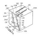
FIG. 1 is a plan view of a part of a tread pattern of a pneumatic tire (studless tire) according to a first embodiment of the present invention, and FIG. 2 is an enlarged perspective view showing a part of the tread part. FIG. The tire includes a plurality of (four in this example)
中間領域16とショルダー領域18には、トレッド幅方向に延びて周方向溝12と交わる横溝20が周方向に所定の間隔をおいて並設されている。これにより、中間領域16とショルダー領域18は、周方向溝12と横溝20とによって区画されるブロック22をトレッド周方向に多数並設してなるブロック列として構成されている。一方、センター領域14には横溝は設けられておらず、そのため、センター領域14は、2本の周方向溝12,12によって区画されてトレッド周方向に連続して延びるリブ24として形成されている。 In the
各ブロック22とリブ24の側面はジグザグ状に形成されている。詳細には、中間領域16のブロック22では、その両側の周方向溝12,12に面した側面22A,22Aに、それぞれ、ブロック表面22Bから溝底部12Aにかけて当該溝12内に段差状に突出するエッジ部26が複数(ここでは2個)設けられ、これにより、ブロック22の両側面22A,22Aがジグザグ状に形成されている。また、ショルダー領域18のブロック22では、周方向溝12に面した片側の側面22Aのみに、同様のエッジ部26が設けられて、ジグザグ状に形成されている。更に、中央領域16のリブ24では、周方向溝12,12に面した両側の側面24A,24Aに、それぞれ、リブ表面24Bから溝底部12Aにかけて同様のエッジ部26が周方向に一定の間隔で設けられて、リブ24の両側面24A,24Aがジグザグ状に形成されている。 The side surfaces of each
エッジ部26は、ブロック側面22Aやリブ側面24Aから略直角に突出形成されている。すなわち、図3に示すように、エッジ部26を構成する段面26Aは、その前後の側面22Aに対する角度θ1,θ2がともに略直角に設定されている。また、その突出代、即ち段面26Aの幅W1は、1mm以上に設定されており、溝12の深さ方向に略一定の幅で形成されている。また、この幅W1は、隣接するエッジ部26,26間の配設間隔よりも十分小さく設定されている。更に、エッジ部26は、この段面26Aがタイヤ回転方向の後方(即ち、タイヤ回転方向の反対方向)に向くように形成されている。 The
図3に示すように、エッジ部26は、周方向溝12の深さ方向において鈍角状の曲部28により側面22Aに沿って階段状に折曲形成されている。すなわち、エッジ部26は、ブロック側面22Aを正面として見て階段状に形成されており、かつ、階段状の各段を構成する曲部28が鈍角状に設定されている。この例では、曲部28は、エッジ部26の上記段面26Aを鈍角に折り曲げることで構成される折曲部であり、該折曲部によりエッジ部26には溝の深さ方向に2つの段部30,30が設けられている。曲部28の角度θ3は、鈍角(90°<θ3<180°)であれば特に限定されないが、120°〜160°程度であることが好ましい。また、段部30がブロック表面22Bに対して平行となるよりも、該表面22Bに対して溝深さ方向に傾斜して形成されていることが好ましい。 As shown in FIG. 3, the
また、図2,3に示されるように、この例では、エッジ部26は、ブロック表面22Bから溝底部12Aに向かってタイヤ回転方向後方に傾斜して延びている。詳細には、エッジ部26は、タイヤ回転方向後方に傾斜した3つの傾斜面部32,32,32と、傾斜面部32間に介設された2つの段部30,30とで構成されている。傾斜面部32の傾斜角度θ4は90°未満であり、特に限定されないが、50°〜80°であることが好ましい。また、段部30の長さL1は1mm以上であることが好ましい。 As shown in FIGS. 2 and 3, in this example, the
以上のエッジ部26の構成は、リブ24の側面24Aに設けたエッジ部26についても同様である。なお、各ブロック22及びリブ24の表面には、トレッド幅方向に延びるサイプ34が設けられている。サイプ34は、幅狭の切込みからなるものであり、この例では波形のジグザグ状に延びて形成されている。 The configuration of the
以上よりなる本実施形態のタイヤであると、上記のようにブロック22やリブ24の側縁部のジグザグ形状を形成するエッジ部26を、溝12の深さ方向において鈍角状の曲部28により階段状に形成したので、図4に示すように、溝12に入ってきた雪や泥が鈍角状の曲部28、特に上記鈍角の段部30のおかげで動きやすくなる(雪の動きを矢印で示す。)。そのため、走行中に雪や泥を徐々に後方に排出することができて、溝詰まりが抑制されるので、スノー性能やマッド性能を向上することができる。なお、エッジ部26を単に傾斜させただけでは、溝12に入ってきた雪や泥が溝の深さ方向の全体で塊となって動くことになるためか、排出効果に劣り、本実施形態のような優れたスノー性能やマッド性能は得られない。 In the tire according to the present embodiment configured as described above, the
(第2実施形態)
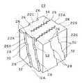
図5は、第2実施形態に係るブロック構成を示したものである。この例では、ブロック22の全ての側面にエッジ部26を設けてジグザグ形状とし、更に、該エッジ部26を上記第1実施形態と同様の階段状に形成している。(Second Embodiment)
FIG. 5 shows a block configuration according to the second embodiment. In this example, the
このように、エッジ部26は、周方向溝12に面した側面22Aだけでなく、横溝20に面した側面22Cにも設けることができ、これにより、横溝20での雪や泥の詰まりを抑制することができる。 In this way, the
また、この例では、周方向溝12に面した両側面22A,22Aにおいて、エッジ部26及びその階段状の傾斜を、左右両側で反対向きに設定している。このように構成することで、タイヤ回転方向を定めないタイヤにも適用することができる。横溝20に面した側面22Cのエッジ部26についても同様に、エッジ部26及びその階段状の傾斜が、前後両側で反対向きに設定されており、これにより、左右両方向の旋回時において横溝20での優れた溝詰まり抑制効果を発揮することができる。 Moreover, in this example, in both
その他の構成は第1実施形態と同様であり、同様の作用効果が奏される。 Other configurations are the same as those of the first embodiment, and the same operational effects are achieved.
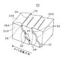
(第3実施形態)
図6は、第3実施形態に係るブロック構成を示したものである。この例では、エッジ部26の階段状の形状を、第1実施形態のように角張った形状とする代わりに、丸みを帯びた波形状としている。(Third embodiment)
FIG. 6 shows a block configuration according to the third embodiment. In this example, the stepped shape of the
すなわち、この例では、エッジ部26は、溝12の深さ方向において鈍角状に湾曲した曲部(湾曲部)28により階段状に形成されており、ブロック側面22Aを正面として見て波形の階段状に形成されている。ここで、かかる湾曲部28について鈍角状とは、湾曲部28の上下両側に直線部がある場合には、その直線部同士のなす角度が鈍角であることをいい、またかかる直線部がない場合には、湾曲部28の上下両側の曲線部の接線のなす角度が鈍角であることをいう。 That is, in this example, the
その他の構成は第1実施形態と同様であり、この例でも、図7に示すように、溝12に入ってきた雪や泥が鈍角状の曲部28、特に上記段部30のおかげで動きやすくなり(雪の動きを矢印で示す。)、そのため、走行中に雪や泥を徐々に後方に排出することができる。 Other configurations are the same as those of the first embodiment. In this example as well, as shown in FIG. 7, snow and mud that have entered the
(第4実施形態)
図8は、第4実施形態に係るタイヤの雪面走行時におけるブロック列の側面概略図である。この例は、エッジ部26の階段状の形状につき、第1実施形態と第2実施形態を組み合わせた例である。(Fourth embodiment)
FIG. 8 is a schematic side view of the block row when the tire according to the fourth embodiment travels on a snow surface. In this example, the first embodiment and the second embodiment are combined with respect to the stepped shape of the
すなわち、この例では、エッジ部26は、鈍角の折曲部28Aと鈍角状の湾曲部28Bとにより階段状に形成されており、傾斜面部32から段部30に至る部分が湾曲部28Bとされ、段部30から傾斜面部32に至る部分が折曲部28Aとされている。 That is, in this example, the
その他の構成は第1実施形態と同様であり、この例でも、溝12に入ってきた雪や泥が鈍角状の段部30のおかげで動きやすくなり(雪の動きを矢印で示す。)、そのため、走行中に雪や泥を徐々に後方に排出することができる。 Other configurations are the same as in the first embodiment, and in this example, snow and mud that have entered the
(第5実施形態)
図9は、第5実施形態に係るタイヤの雪面走行時におけるブロック列の側面概略図である。この例では、エッジ部26の階段状の形状につき、その段部30の数を第1実施形態よりも多く、すなわち段部30を4つ設けている。このようにエッジ部26の階段状の段の数は、一段以上であれば特に限定されない。その他の構成は第1実施形態と同様であり、同様の作用効果が奏される。(Fifth embodiment)
FIG. 9 is a schematic side view of a block row when the tire according to the fifth embodiment travels on a snow surface. In this example, the stepped shape of the
なお、上記各実施形態においては、ブロック22とリブ24を備えるトレッドパターンについて説明したが、本発明はこれに限定されず、ブロックのみ、又はリブのみを持つトレッドパターンにも適用することができ、すなわち、上記エッジ部26の構成は、ブロック及び/又はリブに適用可能である。 In addition, in each said embodiment, although the tread pattern provided with the
上記第1実施形態に係る空気入りラジアルタイヤ(実施例1)と、図10に示したエッジ部構成を持ち、その他は実施例1と同様の比較例のタイヤ(比較例1)とを、タイヤサイズを205/65R15として作製した。得られたタイヤを、トヨタ自動車製クラウン3000cc(FR、AT車)に装着し(リムサイズ:15×6.5JJ)、スノー制動性とスノー加速性を評価した。評価方法は次の通りである。 The pneumatic radial tire according to the first embodiment (Example 1) and the tire of the comparative example (Comparative Example 1) having the edge configuration shown in FIG. The size was 205 / 65R15. The obtained tire was mounted on a Toyota 3000 Crown (FR, AT car) (rim size: 15 × 6.5JJ), and the snow braking performance and snow acceleration performance were evaluated. The evaluation method is as follows.
・スノー制動性:雪上路面にて、速度40km/hからABS制動し、制動距離を測定した。Snow braking ability: ABS braking was performed from a speed of 40 km / h on the road surface on snow, and the braking distance was measured.
・スノー加速性:雪上路面にて、停止状態からLレンジにてアクセルを踏み、エンジンを3500回転/分に合わせ、3500回転/分の状態で20m進んだ時の秒数を測定した。-Snow acceleration: On the road surface on snow, the accelerator was depressed in the L range from the stop state, the engine was adjusted to 3500 rpm, and the number of seconds when the vehicle traveled 20 m at 3500 rpm was measured.
その結果、実施例1によれば、スノー制動性及びスノー加速性ともに、比較例1に対して10%の改善効果が認められ、スノー性能が向上していた。 As a result, according to Example 1, both the snow braking performance and the snow acceleration performance were confirmed to be 10% better than Comparative Example 1, and the snow performance was improved.
本発明の空気入りタイヤは、スタッドレスタイヤ等の冬用タイヤとして、また、マッド性能が要求されるオフロード用タイヤとして、特に好適に利用することができ、更には、これらに限らず、各種空気入りタイヤに利用することができる。 The pneumatic tire of the present invention can be particularly suitably used as a winter tire such as a studless tire, and as an off-road tire that requires a mud performance. Can be used for entering tires.
10…トレッド部、12…周方向溝、12A…溝底部、14…センター領域、16…中間領域、18…ショルダー領域、20…横溝、22…ブロック、22A…側面、22B…表面、24…リブ、24A…側面、24B…表面、26…エッジ部、28…曲部、30…段部、32…傾斜面部 DESCRIPTION OF
Claims (8)
Translated fromJapanese前記陸部の側面に陸部表面から溝底部にかけて当該溝内に突出するエッジ部が設けられ、該エッジ部が、前記陸部の側面を正面として見て、前記溝の深さ方向において鈍角状の曲部により階段状に形成され、
前記エッジ部が前記陸部の側面に複数設けられることで該側面がジクザク状に形成され、前記陸部の側面に対する前記エッジ部の突出幅が、隣接するエッジ部間の配設間隔よりも小さく設定された
ことを特徴とする空気入りタイヤ。In a pneumatic tire having a tread portion with a land portion partitioned by a groove provided on the tread surface,
An edge portion protruding into the groove from the land surface to the groove bottom is provided on the side surface of the land portion, and the edge portion is obtuse in the depth direction of the groove when the side surface of the land portion is viewed as a front surface. are formed stepwise by a curvedportion,
By providing a plurality of the edge portions on the side surface of the land portion, the side surfaces are formed in a zigzag shape, and the protruding width of the edge portion with respect to the side surface of the land portion is smaller than the arrangement interval between adjacent edge portions. Pneumatic tire characterizedby being set .
Priority Applications (3)
| Application Number | Priority Date | Filing Date | Title |
|---|---|---|---|
| JP2006115028AJP5038649B2 (en) | 2006-04-18 | 2006-04-18 | Pneumatic tire |
| DE102007016113ADE102007016113A1 (en) | 2006-04-18 | 2007-04-03 | tire |
| US11/695,901US20070240801A1 (en) | 2006-04-18 | 2007-04-03 | Pneumatic Tire |
Applications Claiming Priority (1)
| Application Number | Priority Date | Filing Date | Title |
|---|---|---|---|
| JP2006115028AJP5038649B2 (en) | 2006-04-18 | 2006-04-18 | Pneumatic tire |
Publications (2)
| Publication Number | Publication Date |
|---|---|
| JP2007283943A JP2007283943A (en) | 2007-11-01 |
| JP5038649B2true JP5038649B2 (en) | 2012-10-03 |
Family
ID=38565034
Family Applications (1)
| Application Number | Title | Priority Date | Filing Date |
|---|---|---|---|
| JP2006115028AExpired - Fee RelatedJP5038649B2 (en) | 2006-04-18 | 2006-04-18 | Pneumatic tire |
Country Status (3)
| Country | Link |
|---|---|
| US (1) | US20070240801A1 (en) |
| JP (1) | JP5038649B2 (en) |
| DE (1) | DE102007016113A1 (en) |
Families Citing this family (25)
| Publication number | Priority date | Publication date | Assignee | Title |
|---|---|---|---|---|
| US20080271827A1 (en)* | 2007-05-03 | 2008-11-06 | Andrew Edward Morrison | Pnuematic tire |
| JP4488083B2 (en)* | 2008-04-11 | 2010-06-23 | 横浜ゴム株式会社 | Pneumatic tire |
| JP4312823B1 (en)* | 2008-07-07 | 2009-08-12 | 横浜ゴム株式会社 | PNEUMATIC TIRE, TIRE MOLDING MOLD, AND METHOD FOR PRODUCING PNEUMATIC TIRE |
| IT1396282B1 (en)* | 2009-09-22 | 2012-11-16 | Bridgestone Corp | WINTER TIRE WITH INCREASED TRACTION CAPACITY ON SNOW COVERS. |
| DE102009044846A1 (en)* | 2009-12-09 | 2011-06-16 | Continental Reifen Deutschland Gmbh | Tread pattern of a pneumatic vehicle tire |
| JP5580124B2 (en)* | 2010-07-12 | 2014-08-27 | 株式会社ブリヂストン | tire |
| US8863795B2 (en)* | 2010-10-29 | 2014-10-21 | The Goodyear Tire & Rubber Company | Gripping edges for winter tire |
| KR101410822B1 (en)* | 2012-11-22 | 2014-06-23 | 한국타이어 주식회사 | Air Pressure Tire |
| CN104837653B (en)* | 2013-03-06 | 2017-03-29 | 横滨橡胶株式会社 | Pneumatic tire |
| US10350946B2 (en)* | 2013-10-30 | 2019-07-16 | Bridgestone Americas Tire Operations, Llc | Snow tire with directional paddles |
| CN105172480B (en)* | 2014-05-26 | 2018-09-04 | 住友橡胶工业株式会社 | Pneumatic tire |
| EP3204242B1 (en)* | 2014-10-06 | 2021-07-28 | Bridgestone Americas Tire Operations, LLC | Tire traction element |
| JP6449005B2 (en)* | 2014-12-03 | 2019-01-09 | 東洋ゴム工業株式会社 | Pneumatic tire |
| JP6336409B2 (en)* | 2015-05-26 | 2018-06-06 | 住友ゴム工業株式会社 | Winter tires |
| NO2794345T3 (en) | 2015-06-01 | 2018-08-11 | ||
| DE102015211013A1 (en) | 2015-06-16 | 2016-12-22 | Continental Reifen Deutschland Gmbh | Vehicle tires |
| DE102016204576A1 (en) | 2016-03-18 | 2017-09-21 | Continental Reifen Deutschland Gmbh | Vehicle tires |
| JP6790664B2 (en)* | 2016-09-26 | 2020-11-25 | 住友ゴム工業株式会社 | tire |
| JP6891556B2 (en)* | 2017-03-14 | 2021-06-18 | 住友ゴム工業株式会社 | tire |
| JP7098962B2 (en)* | 2018-03-05 | 2022-07-12 | 住友ゴム工業株式会社 | tire |
| JP2019214231A (en)* | 2018-06-11 | 2019-12-19 | 株式会社ブリヂストン | Pneumatic tire |
| JP7136658B2 (en)* | 2018-10-22 | 2022-09-13 | Toyo Tire株式会社 | pneumatic tire |
| JP7409044B2 (en)* | 2019-11-25 | 2024-01-09 | 住友ゴム工業株式会社 | tire |
| JP7389636B2 (en)* | 2019-12-13 | 2023-11-30 | 株式会社ブリヂストン | tire |
| EP4612003A1 (en)* | 2022-11-03 | 2025-09-10 | Pirelli Tyre S.p.A. | Vehicle wheel tyre |
Family Cites Families (21)
| Publication number | Priority date | Publication date | Assignee | Title |
|---|---|---|---|---|
| CA1198043A (en)* | 1981-06-12 | 1985-12-17 | Barry W. Treves | Tyre treads |
| JPS60252006A (en)* | 1984-05-30 | 1985-12-12 | Yokohama Rubber Co Ltd:The | Pneumatic tire |
| JPH0386605A (en)* | 1989-08-30 | 1991-04-11 | Bridgestone Corp | Pneumatic tire having superior drainage performance |
| JPH04278809A (en)* | 1991-03-04 | 1992-10-05 | Yokohama Rubber Co Ltd:The | Pneumatic radial tire |
| US5176766B1 (en)* | 1991-03-08 | 1996-04-30 | Goodyear Tire & Rubber | Pneumatic tire having a unique footprint |
| DE4138687C2 (en)* | 1991-11-25 | 1995-09-14 | Pirelli Reifenwerke | Tread pattern for a vehicle tire |
| DE4138688C2 (en)* | 1991-11-25 | 1995-09-14 | Pirelli Reifenwerke | Tread pattern for a vehicle tire |
| JP3088811B2 (en)* | 1991-12-20 | 2000-09-18 | オーツタイヤ株式会社 | Pneumatic tires with improved on-snow performance |
| FR2692201A1 (en)* | 1992-06-11 | 1993-12-17 | Michelin & Cie | Train with directional tread tires. |
| JPH09136515A (en)* | 1995-11-16 | 1997-05-27 | Yokohama Rubber Co Ltd:The | Pneumatic tire for icy road |
| US5957180A (en)* | 1996-03-05 | 1999-09-28 | The Yokohama Rubber Co., Ltd. | Pneumatic tire including kerfs |
| JP3319977B2 (en)* | 1997-06-09 | 2002-09-03 | オーツタイヤ株式会社 | Lug tires |
| JP3935254B2 (en)* | 1997-12-12 | 2007-06-20 | 東洋ゴム工業株式会社 | Pneumatic tire |
| JP2000211321A (en)* | 1999-01-22 | 2000-08-02 | Bridgestone Corp | Pneumatic tire |
| JP2001354011A (en)* | 2000-06-14 | 2001-12-25 | Bridgestone Corp | Pneumatic tire |
| JP4199541B2 (en)* | 2000-11-28 | 2008-12-17 | クーパー タイヤ アンド ラバー カンパニー | Groove side with serrated part of tire |
| ATE319579T1 (en)* | 2001-08-03 | 2006-03-15 | Pirelli | TIRE ESPECIALLY SUITABLE FOR SNOW-COVERED GROUND |
| US6983777B2 (en)* | 2002-10-15 | 2006-01-10 | The Goodyear Tire & Rubber Company | Tire tread with multi-planar chamfers |
| JP4169256B2 (en)* | 2002-10-18 | 2008-10-22 | 東洋ゴム工業株式会社 | Pneumatic tire |
| US7028733B2 (en)* | 2003-06-23 | 2006-04-18 | The Goodyear Tire & Rubber Company | Pneumatic tire having circumferentially extending rib with chamfers |
| USD502141S1 (en)* | 2004-04-27 | 2005-02-22 | The Goodyear Tire & Rubber Company | Tire tread |
- 2006
- 2006-04-18JPJP2006115028Apatent/JP5038649B2/ennot_activeExpired - Fee Related
- 2007
- 2007-04-03DEDE102007016113Apatent/DE102007016113A1/ennot_activeCeased
- 2007-04-03USUS11/695,901patent/US20070240801A1/ennot_activeAbandoned
Also Published As
| Publication number | Publication date |
|---|---|
| DE102007016113A1 (en) | 2007-11-08 |
| US20070240801A1 (en) | 2007-10-18 |
| JP2007283943A (en) | 2007-11-01 |
Similar Documents
| Publication | Publication Date | Title |
|---|---|---|
| JP5038649B2 (en) | Pneumatic tire | |
| JP5099914B2 (en) | Pneumatic tire | |
| JP5140115B2 (en) | Pneumatic tire | |
| JP4280297B2 (en) | Pneumatic tire | |
| US9079460B2 (en) | Pneumatic tire | |
| KR101793632B1 (en) | Pneumatic tire | |
| JP4873988B2 (en) | Pneumatic tire | |
| WO2012046724A1 (en) | Tire | |
| JP2008074346A (en) | Rough road running pneumatic tire | |
| JP7024465B2 (en) | Pneumatic tires | |
| JP2003146024A (en) | Pneumatic tire | |
| JP2000108615A (en) | Passenger car pneumatic radial tire with directional inclined groove | |
| JPH10230712A (en) | Pneumatic radial tire for all-season passenger car | |
| JP4800610B2 (en) | Pneumatic radial tire | |
| JP2000225815A (en) | Pneumatic tire | |
| JP2008044441A (en) | Pneumatic tire | |
| JPH11342708A (en) | Tire for motor vehicle | |
| JP2004017863A (en) | Pneumatic tire | |
| JP3315366B2 (en) | Pneumatic tire | |
| JP2003226116A (en) | Pneumatic tire | |
| JP2008290521A (en) | Pneumatic tire | |
| JP5711917B2 (en) | tire | |
| JP2008207659A (en) | Pneumatic tire | |
| JP6911389B2 (en) | Pneumatic tires | |
| JP2007022361A (en) | Pneumatic tire |
Legal Events
| Date | Code | Title | Description |
|---|---|---|---|
| A621 | Written request for application examination | Free format text:JAPANESE INTERMEDIATE CODE: A621 Effective date:20081210 | |
| A977 | Report on retrieval | Free format text:JAPANESE INTERMEDIATE CODE: A971007 Effective date:20110425 | |
| A131 | Notification of reasons for refusal | Free format text:JAPANESE INTERMEDIATE CODE: A131 Effective date:20110510 | |
| A521 | Request for written amendment filed | Free format text:JAPANESE INTERMEDIATE CODE: A523 Effective date:20110622 | |
| A131 | Notification of reasons for refusal | Free format text:JAPANESE INTERMEDIATE CODE: A131 Effective date:20120306 | |
| A521 | Request for written amendment filed | Free format text:JAPANESE INTERMEDIATE CODE: A523 Effective date:20120426 | |
| TRDD | Decision of grant or rejection written | ||
| A01 | Written decision to grant a patent or to grant a registration (utility model) | Free format text:JAPANESE INTERMEDIATE CODE: A01 Effective date:20120703 | |
| A01 | Written decision to grant a patent or to grant a registration (utility model) | Free format text:JAPANESE INTERMEDIATE CODE: A01 | |
| A61 | First payment of annual fees (during grant procedure) | Free format text:JAPANESE INTERMEDIATE CODE: A61 Effective date:20120706 | |
| FPAY | Renewal fee payment (event date is renewal date of database) | Free format text:PAYMENT UNTIL: 20150713 Year of fee payment:3 | |
| R150 | Certificate of patent or registration of utility model | Ref document number:5038649 Country of ref document:JP Free format text:JAPANESE INTERMEDIATE CODE: R150 Free format text:JAPANESE INTERMEDIATE CODE: R150 | |
| R250 | Receipt of annual fees | Free format text:JAPANESE INTERMEDIATE CODE: R250 | |
| S531 | Written request for registration of change of domicile | Free format text:JAPANESE INTERMEDIATE CODE: R313531 | |
| R350 | Written notification of registration of transfer | Free format text:JAPANESE INTERMEDIATE CODE: R350 | |
| R250 | Receipt of annual fees | Free format text:JAPANESE INTERMEDIATE CODE: R250 | |
| S533 | Written request for registration of change of name | Free format text:JAPANESE INTERMEDIATE CODE: R313533 | |
| R350 | Written notification of registration of transfer | Free format text:JAPANESE INTERMEDIATE CODE: R350 | |
| LAPS | Cancellation because of no payment of annual fees |