Movatterモバイル変換


[0]ホーム

URL:


JP5038643B2 - Image display device - Google Patents

Image display device
Download PDF

Info

Publication number
JP5038643B2
JP5038643B2JP2006083406AJP2006083406AJP5038643B2JP 5038643 B2JP5038643 B2JP 5038643B2JP 2006083406 AJP2006083406 AJP 2006083406AJP 2006083406 AJP2006083406 AJP 2006083406AJP 5038643 B2JP5038643 B2JP 5038643B2
Authority
JP
Japan
Prior art keywords
image
image data
unit
display
slice
Prior art date
Legal status (The legal status is an assumption and is not a legal conclusion. Google has not performed a legal analysis and makes no representation as to the accuracy of the status listed.)
Expired - Fee Related
Application number
JP2006083406A
Other languages
Japanese (ja)
Other versions
JP2006312026A (en
Inventor
高 増沢
Current Assignee (The listed assignees may be inaccurate. Google has not performed a legal analysis and makes no representation or warranty as to the accuracy of the list.)
Toshiba Corp
Canon Medical Systems Corp
Original Assignee
Toshiba Corp
Toshiba Medical Systems Corp
Priority date (The priority date is an assumption and is not a legal conclusion. Google has not performed a legal analysis and makes no representation as to the accuracy of the date listed.)
Filing date
Publication date
Application filed by Toshiba Corp, Toshiba Medical Systems CorpfiledCriticalToshiba Corp
Priority to JP2006083406ApriorityCriticalpatent/JP5038643B2/en
Publication of JP2006312026ApublicationCriticalpatent/JP2006312026A/en
Application grantedgrantedCritical
Publication of JP5038643B2publicationCriticalpatent/JP5038643B2/en
Expired - Fee Relatedlegal-statusCriticalCurrent
Anticipated expirationlegal-statusCritical

Links

Images

Landscapes

Description

Translated fromJapanese

本発明は、X線CT装置等の画像診断装置により撮像された画像データを表示するための画像表示装置に係り、特に、所望の部位の画像データを適切な分解能と表示方法で効率よく作成して表示することが可能な画像表示装置に関する。  The present invention relates to an image display apparatus for displaying image data captured by an image diagnostic apparatus such as an X-ray CT apparatus, and in particular, efficiently creates image data of a desired part with an appropriate resolution and display method. The present invention relates to an image display device capable of displaying images.

医療分野における画像診断装置の1つとしてX線CT装置がある(例えば特許文献1参照)。X線CT装置は、主に、撮像したX線CT画像の画像処理を行うための3次元ワークステーション(3D−WS:three−dimensional workstation)、各種画像を保存するための画像サーバおよび各種画像を表示するための画像表示装置と画像表示ネットワークを介して通信可能に接続され、X線CT画像診断表示システムが形成される。このうち、画像表示装置および画像サーバにより形成されるシステムは、医用画像保管通信システム(PACS:picture archiving and communication system)などと呼ばれている。  One of diagnostic imaging apparatuses in the medical field is an X-ray CT apparatus (see, for example, Patent Document 1). An X-ray CT apparatus mainly includes a three-dimensional workstation (3D-WS: three-dimensional workstation) for performing image processing of a captured X-ray CT image, an image server for storing various images, and various images. An image display device for display is communicably connected via an image display network to form an X-ray CT image diagnostic display system. Among these, a system formed by an image display device and an image server is called a medical image storage and communication system (PACS).

図15は、従来のX線CT画像診断表示システムの構成図である。  FIG. 15 is a configuration diagram of a conventional X-ray CT image diagnostic display system.

X線CT画像診断表示システム1は、X線CT装置2、3次元ワークステーション3、画像保管装置としての画像サーバ4、画像ビューアとしての画像表示装置5を備える。  The X-ray CT image diagnostic display system 1 includes anX-ray CT apparatus 2, a three-dimensional workstation 3, an image server 4 as an image storage apparatus, and animage display apparatus 5 as an image viewer.

そして、X線CT装置2によるスキャンが実行されると、図示しないX線管から照射され、被検体を透過したX線が検出器6により検出された後、生データとして生データ保存部7に保存される。画像再構成部8は、生データ保存部7に保存された生データを読み込んで画像再構成処理を施すことにより横断面データ(以下、スライス画像データ)を作成し、再構成画像保存部9に書き込む。ここで、技師等のユーザは必要に応じて3D画像作成部10によりスライス画像データから断面変換(MPR:multi−planar reconstruction)画像やMIP(maximum intensity projection)画像等の比較的簡易な3D画像データを作成し、作成された3D画像データは再構成画像保存部9に書き込まれて保存される。  When scanning by theX-ray CT apparatus 2 is executed, X-rays irradiated from an X-ray tube (not shown) and transmitted through the subject are detected by the detector 6 and then stored in the raw data storage unit 7 as raw data. Saved. Theimage reconstruction unit 8 reads the raw data stored in the raw data storage unit 7 and performs image reconstruction processing to create cross-sectional data (hereinafter referred to as slice image data), and the reconstructedimage storage unit 9 Write. Here, a user such as an engineer uses relatively simple 3D image data such as a multi-planar reconstruction (MPR) image or a MIP (maximum intensity projection) image from the slice image data by the 3Dimage creation unit 10 as necessary. And the created 3D image data is written and stored in the reconstructedimage storage unit 9.

次に、再構成画像保存部9から通信部11およびネットワーク12を介してスライス画像データや3D画像データが画像サーバ4および3次元ワークステーション3に送信される。3次元ワークステーション3の通信部13では、X線CT装置2において生成された薄スライス画像データが受信され、受信された薄スライス画像データは3D画像保存部14に書き込まれて保存される。さらに、3D画像作成部15により薄スライス画像データから比較的高度なVR(volume rendering)画像データ、SSD(surface shaded display)画像データ、VE(virtual endoscopy)画像データ等の3D画像データが作成され、作成された3D画像データは3D画像保存部14に書き込まれて保存される。また、このときの薄スライス画像データや3D画像データは適宜表示部16に表示される。  Next, slice image data and 3D image data are transmitted from the reconstructedimage storage unit 9 to the image server 4 and the 3D workstation 3 via thecommunication unit 11 and thenetwork 12. Thecommunication unit 13 of the three-dimensional workstation 3 receives thin slice image data generated by theX-ray CT apparatus 2, and the received thin slice image data is written and stored in the 3Dimage storage unit 14. Further, the 3Dimage creation unit 15 creates relatively high-level VR (volume rendering) image data, SSD (surface shaded display) image data, VE (virtual endoscopic) image data, and the like from the thin slice image data. The created 3D image data is written and stored in the 3Dimage storage unit 14. Further, the thin slice image data and 3D image data at this time are appropriately displayed on thedisplay unit 16.

尚、薄スライス画像データとは、画像のXY平面分解能とZ方向(厚さ)がほぼ同等であるような厚さのスライス画像を指す。このような画像の画素は、等方性ボクセルとして扱うことができるため3D画像処理に適している。おおよそ0.5mm〜2mm程度のスライス画の画像データを薄スライス画像データとしている。  The thin slice image data refers to a slice image having a thickness such that the XY plane resolution of the image and the Z direction (thickness) are substantially equal. Since such image pixels can be handled as isotropic voxels, they are suitable for 3D image processing. Image data of a slice image of about 0.5 mm to 2 mm is used as thin slice image data.

さらに、このように作成された3D画像データは通信部13およびネットワーク12を介して画像サーバ4に送信される。画像サーバ4の通信部17では、X線CT装置2から送信されたスライス画像データおよび3D画像データ、3次元ワークステーション3から送信された3D画像データが受信され、受信されたスライス画像データおよび3D画像データは画像保存部18に書き込まれて保存される。また、必要に応じて、画像保存部18に保存された画像データが記録部19により読み込まれて、記録媒体20に記録される。このとき、画像データの記録履歴等の管理情報が管理部21に与えられる。そして、管理部21により画像保存部18に保存された画像データや記録部19から記録媒体20に記録された画像データが管理される。  Further, the 3D image data created in this way is transmitted to the image server 4 via thecommunication unit 13 and thenetwork 12. Thecommunication unit 17 of the image server 4 receives the slice image data and 3D image data transmitted from theX-ray CT apparatus 2, and the 3D image data transmitted from the three-dimensional workstation 3. The received slice image data and 3D The image data is written and stored in theimage storage unit 18. If necessary, the image data stored in theimage storage unit 18 is read by therecording unit 19 and recorded on therecording medium 20. At this time, management information such as a recording history of the image data is given to themanagement unit 21. Themanagement unit 21 manages image data stored in theimage storage unit 18 and image data recorded on therecording medium 20 from therecording unit 19.

次に、画像表示装置5の入力部22から画像データの検索要求および送信要求が入力されると通信部23およびネットワーク12を介して画像サーバ4の管理部21に送信される。このため管理部21は所望の画像データを画像保存部18から読み込んで通信部17に与えることにより、画像データを画像表示装置5に送信する。  Next, when an image data search request and transmission request are input from theinput unit 22 of theimage display device 5, they are transmitted to themanagement unit 21 of the image server 4 via thecommunication unit 23 and thenetwork 12. Therefore, themanagement unit 21 reads the desired image data from theimage storage unit 18 and gives it to thecommunication unit 17, thereby transmitting the image data to theimage display device 5.

画像表示装置5の通信部23は、画像サーバ4から送信されたスライス画像データを受信し、受信したスライス画像データを表示部24に与える。この結果、表示部24にはスライス画像がタイルあるいはスタック方式で表示され、読影に用いられる。  Thecommunication unit 23 of theimage display device 5 receives the slice image data transmitted from the image server 4 and gives the received slice image data to thedisplay unit 24. As a result, the slice image is displayed on thedisplay unit 24 in a tile or stack manner and used for interpretation.

尚、読影用の画像表示装置5には上記のように単純に画像サーバ4から受信した画像データを並べて、あるいはブラウズして表示する2Dビューアを用いるのが主流であるが、最近は3D画像データを生成する3D機能もあわせもつビューアがしばしば用いられるようになってきた。  The mainstream of theimage display device 5 for image interpretation is a 2D viewer that simply displays the image data received from the image server 4 side by side or browses as described above. Viewers that also have a 3D function for generating images are often used.

また最近は、3次元ワークステーション3により、より多くのスライス画像データにMPR処理を行って、冠状断面画像(コロナル画像)や矢断面画像(サジタル画像)を生成したり、MIP処理等の3D処理を施したりする他、さらにこれらの3D処理技術を基盤とした冠動脈解析や心機能解析等の臨床解析を行うための解析用臨床アプリケーションが利用されて、診断の効率と質の向上が図られている。
特開2000−139897号公報
Recently, MPR processing is performed on more slice image data by the three-dimensional workstation 3 to generate coronal slice images (coronal images) and arrow slice images (sagittal images), and 3D processing such as MIP processing. In addition, clinical applications for analysis such as coronary artery analysis and cardiac function analysis based on these 3D processing technologies are used to improve the efficiency and quality of diagnosis. Yes.
JP 2000-139897 A

画質のよいMPR像等の3D画像を生成し、精度の高い臨床解析を行うためには、解像度の高い、つまり、より大量の薄いスライスデータが必要となる。しかしながら、大量のスライスデータを生成して保存することとなると、画像表示装置5や画像サーバ4のディスク資源を大量に消費することになり、経済性の観点から優れているとはいえない。  In order to generate a 3D image such as a high-quality MPR image and perform a highly accurate clinical analysis, a high resolution, that is, a larger amount of thin slice data is required. However, when a large amount of slice data is generated and stored, a large amount of disk resources of theimage display device 5 and the image server 4 are consumed, which is not excellent from the viewpoint of economy.

これを回避するために、3D画像の作成以外の目的で撮影を行う場合には厚いスライスデータとMPR像のみをX線CT装置2の出力としたり、疾患部位のみを薄いスライスデータにして運用することが行われている。しかし、この方法は撮影時に技師の判断で行われるため、医師が読影する際に必要な精度で画像データを参照することができなくなる恐れがあるという問題がある。  In order to avoid this, when imaging is performed for purposes other than creation of 3D images, only thick slice data and MPR images are used as the output of theX-ray CT apparatus 2, or only diseased sites are used as thin slice data. Things have been done. However, since this method is performed at the discretion of an engineer at the time of photographing, there is a problem that image data may not be referred to with the accuracy required for interpretation by a doctor.

また、CT画像の読影手法は長年アキシャル像に基づいた診断学が確立しているため、MPR像や3D画像は診断の補助として利用し、最終的にはスライスデータを元に診断を下さざるを得ない。しかし、従来の画像表示方法では、スライスデータの画像枚数が多いことから、読影の効率を低下させてしまう恐れがあるという問題がある。  In addition, CT images have been diagnosed based on axial images for many years, so MPR images and 3D images can be used as diagnostic aids. Finally, diagnosis must be performed based on slice data. I don't get it. However, the conventional image display method has a problem that there is a risk that the interpretation efficiency may be lowered because the number of slice data images is large.

特に近年、マルチスライスCTにおいて多列化が進んでおり、膨大な量の画像データが発生するようになっている。そこで、所望の部位の画像を適切な分解能と表示方法で効率よく表示する方法が求められている。ただし、データ通信資源やデータ保管資源を効率的に使うために、無用にスライスデータを発生させることの無いようにしなければならない。  In particular, in recent years, multi-slice CT has become multi-rowed, and an enormous amount of image data is generated. Therefore, a method for efficiently displaying an image of a desired part with an appropriate resolution and display method is required. However, in order to efficiently use data communication resources and data storage resources, it is necessary to avoid generating slice data unnecessarily.

本発明はかかる従来の事情に対処するためになされたものであり、X線CT装置2等の画像診断装置により撮像された画像データのうち、より少ない画像データから所望の部位の画像データを適切な分解能と表示方法で効率よく作成して表示することが可能な画像表示装置を提供することを目的とする。  The present invention has been made in order to cope with such a conventional situation, and among image data captured by an image diagnostic apparatus such as theX-ray CT apparatus 2, image data of a desired part is appropriately obtained from a smaller amount of image data. An object of the present invention is to provide an image display device that can be efficiently created and displayed with a high resolution and display method.

また、本発明に係る画像表示装置は、上述の目的を達成するために、請求項に記載したように、入力部および表示部を備えた画像表示装置において、参照画像を前記表示部に表示させる参照画像表示手段と、前記入力部から取得した指示情報および前記参照画像に基て断面画像データ観察範囲を指定する観察範囲指定手段と、前記断面画像データ厚さを指定する断面厚指定手段と、所定値以下のスライス厚の複数のスライス画像データが前記保存部に保存されていると判断される場合に、前記観察範囲に含まれる前記所定値以下のスライス厚の複数のスライス画像データを用いて、前記指定された厚さの断面画像データが前記観察範囲内に生成されるように所要の厚さのスラブ画像データを生成し、前記生成されたスラブ画像データを前記表示に与えることにより前記断面画像データを表示させるスラブ画像生成手段と、各種のスライス厚のスライス画像データを保存可能な保存部に、前記所定値以下のスライス厚のスライス画像データが保存されていないと判断される場合に、前記所定値以下のスライス厚のスライス画像データの再構成指示を画像再構成手段に送信する画像再構成指示手段と、を有することを特徴とするものである。The image display apparatus according to the present invention, the display in order to achieve the above object, as described in claim1, in the image display device having an input unit and a display unit, a reference image on the display unit a reference image displaymeans for the observation range designatingmeans for designating theobservation range of thecross-sectional plane imagedata have direction information and groupDzu the reference image acquired from the input unit, specifies thethickness ofthe cross-sectional imagedata across-sectional thickness designatingmeans,when a plurality of slice image data of the slice thickness of less than a predetermined value is determined to be stored in the storage unit, the observation range tothe predetermined value or less of the slice thickness multipleof contained using the slice image data,said cross-sectional image data of the specifiedthickness to produce the required thickness of the slab image data to be generated withinthe observation range,the generated slab image data A slab image generatingmeans for displayingthe cross-sectional imagedata by providing to the displayunit,a variety of storage unit capable of saving the slice thickness of the slice image data of the slice image data of the slice thickness of less than the predetermined value is stored Image reconstruction instructing means for transmitting a reconstruction instruction for slice image data having a slice thickness equal to or smaller than the predetermined value to the image reconstruction means when it is determined that the image reconstruction means has not been performed. .

本発明に係る画像表示装置においては、X線CT装置等の画像診断装置により撮像された画像データのうち、より少ない画像データから所望の部位の画像データを適切な分解能と表示方法で効率よく作成して表示することができる。  In the image display apparatus according to the present invention, image data of a desired part is efficiently generated from a smaller amount of image data captured by an image diagnostic apparatus such as an X-ray CT apparatus with an appropriate resolution and display method. Can be displayed.

本発明に係る画像表示装置の実施の形態について添付図面を参照して説明する。  Embodiments of an image display apparatus according to the present invention will be described with reference to the accompanying drawings.

図1は本発明に係る画像表示装置を構成要素とするX線CT画像診断表示システムの第1の実施形態を示す構成図である。  FIG. 1 is a configuration diagram showing a first embodiment of an X-ray CT image diagnostic display system including an image display apparatus according to the present invention as a component.

X線CT画像診断表示システム30は、X線CT装置31、3次元ワークステーション32、画像サーバ33、画像表示装置34を備える。X線CT装置31、3次元ワークステーション32、画像サーバ33および画像表示装置34は、互いにネットワーク35を介して接続される。  The X-ray CT imagediagnostic display system 30 includes anX-ray CT apparatus 31, a three-dimensional workstation 32, animage server 33, and animage display apparatus 34. The X-rayCT apparatus 31, the three-dimensional workstation 32, theimage server 33, and theimage display apparatus 34 are connected to each other via anetwork 35.

X線CT装置31は、検出器36、生データ保存部37、画像再構成部38、再構成画像保存部39、3D画像作成部40および通信部41を備える。  The X-rayCT apparatus 31 includes adetector 36, a rawdata storage unit 37, animage reconstruction unit 38, a reconstructionimage storage unit 39, a 3Dimage creation unit 40, and acommunication unit 41.

検出器36は、スキャンにより図示しないX線管から照射され、被検体を透過したX線を検出して生データを生成することにより、生データを収集する機能と、収集した生データを生データ保存部37に書き込む機能とを有する。  Thedetector 36 irradiates an X-ray tube (not shown) by scanning, detects X-rays transmitted through the subject, and generates raw data, thereby generating raw data and the collected raw data as raw data. A function of writing to thestorage unit 37.

このため、生データ保存部37には生データが保存される。生データ保存部37は、ディスク等の記録媒体や記録装置により構成することができる。  For this reason, raw data is stored in the rawdata storage unit 37. The rawdata storage unit 37 can be configured by a recording medium such as a disk or a recording device.

画像再構成部38は、生データ保存部37に保存された生データを読み込んで画像再構成処理を施すことにより、生データからアキシャル(Axial)画像であるスライス画像データを作成する機能と、作成したスライス画像データを再構成画像保存部39に書き込む機能を有する。  Theimage reconstruction unit 38 reads the raw data stored in the rawdata storage unit 37 and performs image reconstruction processing, thereby creating slice image data that is an axial image from the raw data, The slice image data is written in the reconstructedimage storage unit 39.

このため、再構成画像保存部39には、スライス画像データが保存される。再構成画像保存部39は、ディスク等の記録媒体や記録装置により構成することができる。ここで、スライス画像データを作成する際には、撮影位置(部位)、スライス厚、拡大率、撮影視野(FOV:field of view)等のパラメータが与えられ、これらパラメータに従ってスライス画像データが作成される。通常の検査では、部位によるプリセット等の撮影条件によってパラメータが決定され、連続的にスライス画像データが作成される。  Therefore, slice image data is stored in the reconstructedimage storage unit 39. The reconstructedimage storage unit 39 can be configured by a recording medium such as a disk or a recording device. Here, when creating slice image data, parameters such as an imaging position (part), slice thickness, magnification, and field of view (FOV) are given, and slice image data is generated according to these parameters. The In a normal examination, parameters are determined according to imaging conditions such as a preset depending on a region, and slice image data is continuously created.

一般に、スライス厚が0.5mm〜2mm程度のスライス画像データは薄スライス(Thin Slice)画像データと呼ばれ、スライス厚が2mmを超えるスライス画像データは厚スライス(Thick Slice)画像データと呼ばれる。通常厚スライス画像データのスライス厚は10mm程度以下である。  In general, slice image data having a slice thickness of about 0.5 mm to 2 mm is referred to as thin slice image data, and slice image data having a slice thickness exceeding 2 mm is referred to as thick slice image data. The slice thickness of the normal thick slice image data is about 10 mm or less.

近年では、X線CT装置31の高性能化によりスキャン時間の短縮と画像の分解能向上が図られている。例えば、20秒程度で被検体の上半身全体を撮影することができ、撮影して得られた画像データを薄スライス画像データとして出力できるX線CT装置31も登場している。尚、1つの画像データをスライス厚が0.5mmのスライス画像データで構成すると、スライス画像データの数は1200枚程度となる。  In recent years, theX-ray CT apparatus 31 has been improved in performance to shorten the scan time and improve the image resolution. For example, anX-ray CT apparatus 31 that can image the entire upper body of a subject in about 20 seconds and can output image data obtained by imaging as thin slice image data has also appeared. If one piece of image data is composed of slice image data having a slice thickness of 0.5 mm, the number of slice image data is about 1200.

3D画像作成部40は、再構成画像保存部39からスライス画像データを読み込んで、3D画像データを作成する機能と、作成した3D画像データを再構成画像保存部39に書き込む機能とを有する。3D画像データとしては、断面画像としてのコロナル画像データやサジタル画像データ等のMPR画像データ、MIP画像データ、MinIP(minimum intensity projection)画像データ、スラブ画像データ、VR画像データ、SSD画像データ、VE画像データ等の画像データが挙げられる。そして、アキシャル画像データ(スライス画像データ)から、これらの3D画像データを再構成する機能は3D機能と呼ばれる。  The 3Dimage creation unit 40 has a function of reading slice image data from the reconstructedimage storage unit 39 and creating 3D image data, and a function of writing the created 3D image data into the reconstructedimage storage unit 39. The 3D image data includes MPR image data such as coronal image data and sagittal image data as a cross-sectional image, MIP image data, MinIP (minimum intensity projection) image data, slab image data, VR image data, SSD image data, and VE image. And image data such as data. A function for reconstructing these 3D image data from the axial image data (slice image data) is called a 3D function.

近年のX線CT装置31には、このようにコンソールで簡易に3D画像を作成する3D機能が備えられ、MPR画像やMIP画像を作成することができる。  TheX-ray CT apparatus 31 in recent years is provided with a 3D function for easily creating a 3D image with the console as described above, and can create an MPR image or an MIP image.

通信部41は、再構成画像保存部39からスライス画像データや3D画像データを読み込んで、ネットワーク35を介して3次元ワークステーション32や画像サーバ33に送信する機能を有する。  Thecommunication unit 41 has a function of reading slice image data and 3D image data from the reconstructedimage storage unit 39 and transmitting them to the three-dimensional workstation 32 and theimage server 33 via thenetwork 35.

つまり、MPR画像データやMIP画像データ等の簡易な3D画像データは、診断の際における読影に有効である場合があるため、検査部位や種別によっては技師が3D画像作成部40で3D画像データを作成し、作成した3D画像データを通信部41からネットワーク35を介して画像サーバ33に転送できるように構成されている。  That is, since simple 3D image data such as MPR image data and MIP image data may be effective for interpretation at the time of diagnosis, an engineer uses the 3Dimage creation unit 40 to obtain 3D image data depending on the examination site and type. The created 3D image data can be transferred from thecommunication unit 41 to theimage server 33 via thenetwork 35.

3次元ワークステーション32は、通信部42、3D画像保存部43、3D画像作成部44および表示部45とを備え、X線CT装置31において生成された薄スライス画像データから3D画像データを作成して画像サーバ33に転送する機能を有する。そして、3次元ワークステーション32を技師や医師が操作することにより3D画像データを作成し、画像サーバ33に出力して保存することができるように構成される。  The three-dimensional workstation 32 includes acommunication unit 42, a 3Dimage storage unit 43, a 3Dimage creation unit 44, and adisplay unit 45, and creates 3D image data from the thin slice image data generated by theX-ray CT apparatus 31. And a function of transferring to theimage server 33. The engineer or doctor operates the three-dimensional workstation 32 to create 3D image data, which can be output to theimage server 33 and stored.

通信部42は、ネットワーク35を介してX線CT装置31や画像サーバ33との間で画像データを送受信する機能を有する。すなわち、通信部42は、X線CT装置31から受信した画像データを3D画像保存部43に書き込む一方、3D画像保存部43から読み込んだ画像データを画像サーバ33に送信する機能を有する。X線CT装置31からは薄スライス画像データが通信部42によって受信され、3D画像保存部43には薄スライス画像データが書き込まれる。また、3D画像保存部43から通信部42により読み込まれた3D画像データが画像サーバ33に送信される。  Thecommunication unit 42 has a function of transmitting / receiving image data to / from theX-ray CT apparatus 31 and theimage server 33 via thenetwork 35. That is, thecommunication unit 42 has a function of writing the image data received from theX-ray CT apparatus 31 to the 3Dimage storage unit 43 and transmitting the image data read from the 3Dimage storage unit 43 to theimage server 33. Thin slice image data is received from theX-ray CT apparatus 31 by thecommunication unit 42, and thin slice image data is written in the 3Dimage storage unit 43. In addition, 3D image data read by thecommunication unit 42 from the 3Dimage storage unit 43 is transmitted to theimage server 33.

3D画像作成部44は、3D画像保存部43から薄スライス画像データを読み込んで、通常の3D画像データの他、比較的高度なVR画像データ、SSD画像データ、VE画像データ等の3D画像データを作成する3D機能と、3D機能を応用した冠動脈解析や左室容積の解析等の臨床解析を行う機能とを有する。3D画像作成部44は、薄スライス画像データ、3D画像データおよび臨床解析の結果等の情報を表示部45に与えて表示させることができる。また、3D画像作成部44により作成された3D画像データは、3D画像保存部43に書き込まれる。  The 3Dimage creation unit 44 reads the thin slice image data from the 3Dimage storage unit 43, and in addition to normal 3D image data, 3D image data such as relatively advanced VR image data, SSD image data, and VE image data. It has a 3D function to be created and a function to perform clinical analysis such as coronary artery analysis and left ventricular volume analysis using the 3D function. The 3Dimage creation unit 44 can give information such as thin slice image data, 3D image data, and results of clinical analysis to thedisplay unit 45 for display. The 3D image data created by the 3Dimage creation unit 44 is written in the 3Dimage storage unit 43.

表示部45は、3D画像作成部44から受けた薄スライス画像データ、3D画像データおよび臨床解析の結果等の情報を表示させる機能を有する。  Thedisplay unit 45 has a function of displaying information such as thin slice image data, 3D image data, and clinical analysis results received from the 3Dimage creation unit 44.

3D画像保存部43には、通信部42がX線CT装置31から受信した薄スライス画像データと、3D画像作成部44によって作成された3D画像データとが保存される。  The 3Dimage storage unit 43 stores the thin slice image data received by thecommunication unit 42 from theX-ray CT apparatus 31 and the 3D image data created by the 3Dimage creation unit 44.

画像サーバ33は、通信部46、画像保存部47、記録部48、管理部49を備え、X線CT装置31や3次元ワークステーション32において作成された3D画像データやスライス画像データ等の画像データを受信して保存する一方、画像表示装置34にこれらの画像データを送信する機能を有する。  Theimage server 33 includes acommunication unit 46, animage storage unit 47, arecording unit 48, and amanagement unit 49, and image data such as 3D image data and slice image data created in theX-ray CT apparatus 31 and the three-dimensional workstation 32. Is received and stored, and theimage display device 34 has a function of transmitting these image data.

通信部46は、X線CT装置31や3次元ワークステーション32において作成された3D画像データやスライス画像データ等の画像データを受信して画像保存部47に書き込む一方、画像保存部47から画像データを読み込んで、画像表示装置34に送信する機能を有する。また、通信部46は、画像サーバ33の外部と管理部49との間においてネットワーク35を経由して情報を送受信する機能を有する。  Thecommunication unit 46 receives image data such as 3D image data and slice image data created by theX-ray CT apparatus 31 and the three-dimensional workstation 32 and writes the image data to theimage storage unit 47. Is read and transmitted to theimage display device 34. Thecommunication unit 46 has a function of transmitting and receiving information between the outside of theimage server 33 and themanagement unit 49 via thenetwork 35.

画像保存部47には、通信部46により受信された3D画像データや厚スライス画像データ等の画像データが保存される。画像保存部47は、ハードディスクにより構成することができる。  Theimage storage unit 47 stores image data such as 3D image data and thick slice image data received by thecommunication unit 46. Theimage storage unit 47 can be configured by a hard disk.

記録部48は、画像保存部47に保存された画像データを読み込んで、DVD(Digital Versatile Disc)や記録テープ等の記録媒体50に記録する機能を有する。また、記録部48からは、画像データの記録履歴等の管理情報が管理部49に与えられる。  Therecording unit 48 has a function of reading the image data stored in theimage storage unit 47 and recording it on arecording medium 50 such as a DVD (Digital Versatile Disc) or a recording tape. Management information such as a recording history of image data is given to themanagement unit 49 from therecording unit 48.

管理部49は、画像保存部47に保存された画像データや記録部48から記録媒体50に記録された画像データを管理する機能を有する。特に、ネットワーク35を経由した外部からの画像データの検索要求を通信部46から受信して、検索結果を通信部46を介して応答したり、対応する画像データを要求元又は要求元から指示された装置に通信部46を介して送信する機能を有する。  Themanagement unit 49 has a function of managing image data stored in theimage storage unit 47 and image data recorded on therecording medium 50 from therecording unit 48. In particular, a search request for image data from the outside via thenetwork 35 is received from thecommunication unit 46, the search result is responded via thecommunication unit 46, and the corresponding image data is instructed from the request source or the request source. A function of transmitting to the device via thecommunication unit 46.

画像表示装置34は、画像サーバ33に保存された画像データを検索し、画像サーバ33から所望の画像データをネットワーク35を介して受信することにより取得する機能と、取得した画像データを表示する機能とを有する。そのために、画像表示装置34には、通信部51、取得画像保存部52、入力部53、表示部54、観察範囲指定部55、画像枚数指定部56、スラブ画像生成部57、MPR画像作成部58が備えられる。  Theimage display device 34 retrieves image data stored in theimage server 33, acquires a desired image data from theimage server 33 via thenetwork 35, and displays the acquired image data And have. Therefore, theimage display device 34 includes acommunication unit 51, an acquiredimage storage unit 52, aninput unit 53, adisplay unit 54, an observationrange specification unit 55, an imagenumber specification unit 56, a slabimage generation unit 57, and an MPR image generation unit. 58 is provided.

通信部51は、入力部53から受けた画像データの検索要求をネットワーク35を介して画像サーバ33に送信する一方、画像サーバ33から所望の画像データを受信して取得画像保存部52に書き込む機能を有する。画像サーバ33からは、薄スライス画像データおよびコロナル画像データやサジタル画像データ等のMPR画像データとされる。  Thecommunication unit 51 transmits a search request for image data received from theinput unit 53 to theimage server 33 via thenetwork 35, and receives desired image data from theimage server 33 and writes it in the acquiredimage storage unit 52. Have From theimage server 33, MPR image data such as thin slice image data, coronal image data, and sagittal image data is used.

このため、取得画像保存部52には、画像サーバ33からネットワーク35を介して取得した薄スライス画像データおよびMPR画像データ等の画像データが保存される。  Therefore, the acquiredimage storage unit 52 stores image data such as thin slice image data and MPR image data acquired from theimage server 33 via thenetwork 35.

入力部53は、マウスやキーボード等の入力装置で構成され、所要の情報を入力する機能を有する。  Theinput unit 53 includes an input device such as a mouse or a keyboard, and has a function of inputting required information.

表示部54は、観察範囲指定部55、画像枚数指定部56、スラブ画像生成部57およびMPR画像作成部58から受けた画像データを表示させる機能を有する。表示部54は、医用画像専用の高輝度、高解像度の白黒モニタで構成される場合が多く、例えば、2500×2000で縦長のポートレートを表示可能なLCD(Liquid Crystal Display)モニタを用いて表示を行うようにすることができる。  Thedisplay unit 54 has a function of displaying the image data received from the observationrange designating unit 55, the imagenumber designating unit 56, the slabimage generating unit 57, and the MPRimage creating unit 58. Thedisplay unit 54 is often composed of a high-intensity, high-resolution monochrome monitor dedicated to medical images. For example, thedisplay unit 54 is displayed using an LCD (Liquid Crystal Display) monitor capable of displaying a portrait portrait of 2500 × 2000. Can be done.

観察範囲指定部55は、表示部54に表示させるアキシャル画像の表示範囲、すなわち観察範囲を指定するために必要な画像データを表示部54に与えて表示させる一方、入力部53からアキシャル画像の表示範囲の指示情報を取得してアキシャル画像の表示範囲を設定する機能と、設定したアキシャル画像の表示範囲を観察範囲情報としてスラブ画像生成部57に与える機能とを有する。ここで、観察範囲指定部55は、後述するMPR画像作成部58により参照用のMPR画像を表示させるために作成されるMPR画像データを参照し、このMPR画像データと入力部53から受けたアキシャル画像の表示範囲の指示情報とから幾何学的な位置関係に従ってアキシャル画像の表示範囲を設定するように構成される。  The observationrange designating unit 55 provides thedisplay unit 54 with image data necessary for designating the display range of the axial image to be displayed on thedisplay unit 54, that is, the observation range, while displaying the axial image from theinput unit 53. It has a function of acquiring range instruction information and setting the display range of an axial image, and a function of giving the set display range of an axial image to the slabimage generation unit 57 as observation range information. Here, the observationrange designation unit 55 refers to the MPR image data created in order to display the MPR image for reference by the MPRimage creation unit 58 described later, and receives the MPR image data and the axial received from theinput unit 53. The display range of the axial image is set according to the geometric positional relationship from the instruction information of the display range of the image.

アキシャル画像の範囲を指定するために必要な画像データとしては、例えばスクロールバー等の図形や記号を画像として表示させるためのデータとすることができる。つまりGUI(Graphical User Interface)技術により観察範囲指定部55を構築することができる。  As the image data necessary for designating the range of the axial image, for example, data such as a graphic such as a scroll bar or a symbol can be displayed as an image. That is, the observationrange designation unit 55 can be constructed by GUI (Graphical User Interface) technology.

画像枚数指定部56は、表示部54に表示させるアキシャル画像の枚数を指定するために必要な画像データを表示部54に与えて表示させる一方、入力部53からアキシャル画像の表示枚数および厚さのいずれか一方の指示情報を取得してアキシャル画像の表示枚数および厚さのいずれか一方を設定する機能と、設定したアキシャル画像の表示枚数および厚さのいずれかをスラブ画像生成部57に与える機能とを有する。  The number-of-images designation unit 56 gives thedisplay unit 54 image data necessary for designating the number of axial images to be displayed on thedisplay unit 54, while displaying the number of axial images displayed and the thickness from theinput unit 53. A function of acquiring any one of the instruction information and setting one of the number of displayed axial images and the thickness, and a function of giving the set number of displayed axial images and the thickness to the slabimage generating unit 57 And have.

アキシャル画像の表示枚数または厚さを指定するために必要な画像データとしては、アキシャル画像の範囲を指定するために必要な画像データと同様に、例えばスクロールバー等の図形や記号を画像として表示させるためのデータとすることができる。つまりGUI技術により画像枚数指定部56を構築することができる。  As the image data necessary for designating the number of display images or the thickness of the axial image, for example, graphics and symbols such as a scroll bar are displayed as an image in the same manner as the image data necessary for designating the range of the axial image. Data. That is, the imagenumber designation unit 56 can be constructed by the GUI technique.

尚、アキシャル画像の表示枚数や厚さの指示は、枚数や厚さそのものを数値として指示する他、隣接するアキシャル画像間の距離等のような間接的な情報を用いて指示することもできる。  The number of axial images to be displayed and the thickness can be instructed by using indirect information such as the distance between adjacent axial images, in addition to instructing the number of sheets or the thickness itself as a numerical value.

スラブ画像生成部57は、観察範囲指定部55から受けた観察範囲情報に従って、取得画像保存部52から観察範囲に含まれる複数の薄スライス画像データを読み込んで、観察範囲内に画像枚数指定部56から受けた枚数および厚さのいずれかのアキシャル画像が生成されるように所要の厚さのスラブ画像データを生成する機能と、生成したスラブ画像データを表示部54に与えて表示させる機能とを有する。  The slabimage generation unit 57 reads a plurality of thin slice image data included in the observation range from the acquiredimage storage unit 52 according to the observation range information received from the observationrange specification unit 55, and sets the number ofimages specification unit 56 within the observation range. A function of generating slab image data of a required thickness so that an axial image of any of the number and thickness received from is generated, and a function of providing the generated slab image data to thedisplay unit 54 for display Have.

MPR画像作成部58は、取得画像保存部52から薄スライス画像データを読み込んで、MPR処理を行うことによりコロナル画像データやサジタル画像データ等のMPR画像データを作成する機能と、作成したMPR画像データを表示部54に与えることによりMPR画像を表示させる機能とを有する。また、MPR画像作成部58は、アキシャル画像の表示範囲の設定のために参照できるようにMPR画像データを観察範囲指定部55に与えるように構成される。そして、アキシャル画像の表示範囲である観察範囲は、表示部54に表示されたサジタル画像あるいはコロナル画像を参照しつつ指定できるように構成される。また、アキシャル画像の表示枚数や厚さも、表示部54に表示されたサジタル画像あるいはコロナル画像を参照しつつ指定できるように構成される。  The MPRimage creation unit 58 reads the thin slice image data from the acquiredimage storage unit 52 and performs MPR processing to create MPR image data such as coronal image data and sagittal image data, and the created MPR image data Is provided to thedisplay unit 54 to display an MPR image. In addition, the MPRimage creation unit 58 is configured to give MPR image data to the observationrange designation unit 55 so that it can be referred to for setting the display range of the axial image. An observation range that is a display range of the axial image is configured so that it can be specified with reference to a sagittal image or a coronal image displayed on thedisplay unit 54. Further, the number and thickness of the displayed axial images can be specified with reference to the sagittal image or the coronal image displayed on thedisplay unit 54.

次に画像表示装置34の動作および作用について説明する。  Next, the operation and action of theimage display device 34 will be described.

図2は、図1に示す画像表示装置34において、観察範囲および表示枚数を指定してアキシャル画像を表示させる際の流れを示すフローチャートであり、図中Sに数字を付した符号はフローチャートの各ステップを示す。  FIG. 2 is a flowchart showing the flow of displaying an axial image by designating the observation range and the number of sheets to be displayed in theimage display apparatus 34 shown in FIG. Steps are shown.

まず予めX線CT装置31において生成された画像データから適宜3D画像データ等の画像データが作成され、画像サーバ33に保存される。すなわち、X線CT装置31によるスキャンが実行され、図示しないX線管から照射され、被検体を透過したX線が検出器36により検出された後、生データとして生データ保存部37に保存される。画像再構成部38は、生データ保存部37に保存された生データを読み込んで画像再構成処理を施すことによりスライス画像データを作成し、再構成画像保存部39に書き込む。ここで、技師等のユーザは必要に応じて3D画像作成部40によりスライス画像データからMPR画像やMIP画像等の比較的簡易な3D画像データを作成し、作成された3D画像データは再構成画像保存部39に書き込まれて保存される。  First, image data such as 3D image data is appropriately generated from image data generated in advance by theX-ray CT apparatus 31 and stored in theimage server 33. That is, scanning by theX-ray CT apparatus 31 is executed, and X-rays irradiated from an X-ray tube (not shown) and transmitted through the subject are detected by thedetector 36, and then stored as raw data in the rawdata storage unit 37. The Theimage reconstruction unit 38 reads the raw data stored in the rawdata storage unit 37 and performs image reconstruction processing to create slice image data and writes the slice image data in the reconstructedimage storage unit 39. Here, a user such as an engineer creates relatively simple 3D image data such as an MPR image or MIP image from the slice image data by the 3Dimage creation unit 40 as necessary, and the created 3D image data is a reconstructed image. It is written and stored in thestorage unit 39.

そして、再構成画像保存部39から通信部41およびネットワーク35を介してスライス画像データや3D画像データが画像サーバ33および3次元ワークステーション32に送信される。3次元ワークステーション32の通信部42では、X線CT装置31において生成された薄スライス画像データが受信され、受信された薄スライス画像データは3D画像保存部43に書き込まれて保存される。さらに、3D画像作成部44により薄スライス画像データから比較的高度なVR画像データ、SSD画像データ、VE画像データ等の3D画像データが作成され、作成された3D画像データは3D画像保存部43に書き込まれて保存される。また、このときの薄スライス画像データや3D画像データは適宜表示部45に表示される。  Then, slice image data and 3D image data are transmitted from the reconstructedimage storage unit 39 to theimage server 33 and the3D workstation 32 via thecommunication unit 41 and thenetwork 35. Thecommunication unit 42 of the three-dimensional workstation 32 receives the thin slice image data generated in theX-ray CT apparatus 31, and the received thin slice image data is written and stored in the 3Dimage storage unit 43. Further, the 3Dimage creation unit 44 creates relatively advanced 3D image data such as VR image data, SSD image data, and VE image data from the thin slice image data, and the created 3D image data is stored in the 3Dimage storage unit 43. Written and saved. Further, the thin slice image data and the 3D image data at this time are appropriately displayed on thedisplay unit 45.

そして、このように作成された3D画像データは通信部42およびネットワーク35を介して画像サーバ33に送信される。画像サーバ33の通信部46では、X線CT装置31から送信されたスライス画像データおよび3D画像データ、3次元ワークステーション32から送信された3D画像データが受信され、受信されたスライス画像データおよび3D画像データは画像保存部47に書き込まれて保存される。また、必要に応じて、画像保存部47に保存された画像データが記録部48により読み込まれて、記録媒体50に記録される。このとき、画像データの記録履歴等の管理情報が管理部49に与えられる。そして、管理部49により画像保存部47に保存された画像データや記録部48から記録媒体50に記録された画像データが管理される。  The 3D image data created in this way is transmitted to theimage server 33 via thecommunication unit 42 and thenetwork 35. Thecommunication unit 46 of theimage server 33 receives the slice image data and 3D image data transmitted from theX-ray CT apparatus 31, and the 3D image data transmitted from the three-dimensional workstation 32. The received slice image data and 3D The image data is written and stored in theimage storage unit 47. If necessary, the image data stored in theimage storage unit 47 is read by therecording unit 48 and recorded on therecording medium 50. At this time, management information such as a recording history of image data is given to themanagement unit 49. Themanagement unit 49 manages image data stored in theimage storage unit 47 and image data recorded on therecording medium 50 from therecording unit 48.

次に、ステップS1において、画像表示装置34の入力部53の操作により、薄スライス画像データやMPR画像データ等の所望の画像データの検索要求および送信要求が通信部51に与えられ、ネットワーク35を介して画像サーバ33の管理部49に送信される。このため、管理部49は画像保存部47を検索し、要求された画像データを読み込む。  Next, in step S <b> 1, a search request and a transmission request for desired image data such as thin slice image data and MPR image data are given to thecommunication unit 51 by operating theinput unit 53 of theimage display device 34. To themanagement unit 49 of theimage server 33. Therefore, themanagement unit 49 searches theimage storage unit 47 and reads the requested image data.

次に、ステップS2において、画像サーバ33の管理部49が画像保存部47から読み込んだ画像データは、通信部46およびネットワーク35を介して、画像表示装置34に送信される。このため、画像表示装置34の通信部51により画像サーバ33から送信された画像データが受信され、受信された画像データは取得画像保存部52に保存される。  Next, instep S 2, the image data read from theimage storage unit 47 by themanagement unit 49 of theimage server 33 is transmitted to theimage display device 34 via thecommunication unit 46 and thenetwork 35. Therefore, the image data transmitted from theimage server 33 is received by thecommunication unit 51 of theimage display device 34, and the received image data is stored in the acquiredimage storage unit 52.

次に、ステップS3において、MPR画像作成部58は、取得画像保存部52から薄スライス画像データを読み込んで、MPR処理を行うことによりコロナル画像データやサジタル画像データ等のMPR画像データを作成し、作成したMPR画像データを表示部54に与えることによりMPR画像を表示させる。  Next, in step S3, the MPRimage creation unit 58 reads the thin slice image data from the acquiredimage storage unit 52 and performs MPR processing to create MPR image data such as coronal image data and sagittal image data. The MPR image is displayed by giving the created MPR image data to thedisplay unit 54.

図3は、図1の画像表示装置34における表示部54に表示される画面の一例を示す図である。  FIG. 3 is a diagram showing an example of a screen displayed on thedisplay unit 54 in theimage display device 34 of FIG.

表示部54には例えば図3のような画像がウィンドウ形式で表示される。すなわち、図3に示す表示部54の画面例において、左側にコロナル画像の表示領域A1が、中央にサジタル画像の表示領域A2が、右側にアキシャル画像の表示領域A3がそれぞれ設けられる。そして、MPR画像作成部58により作成されたコロナル画像およびサジタル画像がそれぞれコロナル画像の表示領域A1およびサジタル画像の表示領域A2に表示される。ただし、図3では、サジタル画像を省略している。  For example, an image as shown in FIG. 3 is displayed on thedisplay unit 54 in a window format. That is, in the screen example of thedisplay unit 54 shown in FIG. 3, a coronal image display area A1 is provided on the left side, a sagittal image display area A2 is provided on the center, and an axial image display area A3 is provided on the right side. Then, the coronal image and the sagittal image created by the MPRimage creating unit 58 are displayed in the coronal image display area A1 and the sagittal image display area A2, respectively. However, in FIG. 3, the sagittal image is omitted.

また、表示部54の表示領域A1には、MPR画像作成部58により作成された画像を表示するのではなく、X線CT装置31で撮影計画を立てるために撮影されるスカウト画像を表示してもよい。スカウト画像とスライス画像との座標位置関係は、画像に付帯する基準位置(例えば、画像の左上の点)の寝台座標と画素当たりの距離の情報を使って特定することができる。  In addition, the display area A1 of thedisplay unit 54 does not display the image created by the MPRimage creation unit 58, but displays a scout image photographed for making an imaging plan by theX-ray CT apparatus 31. Also good. The coordinate position relationship between the scout image and the slice image can be specified by using the bed coordinate of the reference position (for example, the upper left point of the image) attached to the image and the information on the distance per pixel.

尚、薄スライス画像データが2000枚程度含まれるような広い領域の撮影を行った場合には、コロナル画像およびサジタル画像が頚部から下肢に亘る縦長の画像となる。そこで、そのような場合を想定してコロナル画像の表示領域A1およびサジタル画像の表示領域A2を縦長とすると利便性の向上に繋がる。  Note that when a wide area including about 2000 pieces of thin slice image data is captured, the coronal image and the sagittal image are vertically long images extending from the neck to the lower limbs. Accordingly, assuming such a case, if the coronal image display area A1 and the sagittal image display area A2 are vertically long, the convenience is improved.

このとき、観察範囲指定部55は、例えば観察範囲Dを指定するためのバー60、60を表示部54に表示させる。このため、マウス等の入力部53の操作によりバー60、60を移動させることにより観察範囲の指定が可能となる。また、アキシャル画像の表示枚数や厚さの指定も可能となる。ここでは、アキシャル画像の表示枚数を指定する場合について説明する。  At this time, the observationrange designation unit 55 causes thedisplay unit 54 to displaybars 60 and 60 for designating the observation range D, for example. Therefore, the observation range can be specified by moving thebars 60 and 60 by operating theinput unit 53 such as a mouse. It is also possible to specify the number of displayed axial images and the thickness. Here, a case where the number of axial images to be displayed is designated will be described.

次に、ステップS4において、入力部53の操作により観察範囲およびアキシャル画像の表示枚数が指定される。すなわち、まずマウス等の入力部53のスクロール機能によりコロナル画像またはサジタル画像上に表示された2本のバー60、60が移動せしめられ、観察範囲指定部55により観察範囲が指定される。  Next, in step S4, the observation range and the number of displayed axial images are designated by operating theinput unit 53. That is, first, the twobars 60 and 60 displayed on the coronal image or the sagittal image are moved by the scroll function of theinput unit 53 such as a mouse, and the observation range is designated by the observationrange designation unit 55.

さらに、指定された観察範囲内において、表示させるアキシャル画像の枚数が入力部53の操作により指示される。アキシャル画像の枚数の指示は、枚数を数値として入力部53から入力する他、アキシャル画像のスライス厚や隣接するアキシャル画像間の距離を入力部53から入力することにより行うことができる。また、一旦、観察範囲が指定された後は、アキシャル画像の表示枚数についてもマウス等の入力部53のスクロール機能によって指定できるようにすることも可能である。この場合、指定された観察範囲内に観察範囲をスライスするための線分を表示させると利便性を向上させることができる。  Further, the number of axial images to be displayed is designated by operating theinput unit 53 within the designated observation range. The number of axial images can be instructed by inputting the number of images as a numerical value from theinput unit 53 or by inputting the slice thickness of the axial image or the distance between adjacent axial images from theinput unit 53. In addition, once the observation range is designated, the number of axial images to be displayed can be designated by the scroll function of theinput unit 53 such as a mouse. In this case, convenience can be improved by displaying a line segment for slicing the observation range within the designated observation range.

そして、入力部53から入力された情報が画像枚数指定部56により取得され、表示部54に表示させるアキシャル画像の枚数が設定される。そうすると、観察範囲指定部55からは観察範囲情報が、画像枚数指定部56からはアキシャル画像の表示枚数情報がそれぞれスラブ画像生成部57に与えられる。  The information input from theinput unit 53 is acquired by the imagenumber designation unit 56, and the number of axial images to be displayed on thedisplay unit 54 is set. Then, the observation range information is given from the observationrange designation unit 55 and the display number information of the axial image is given from the imagenumber designation unit 56 to the slabimage generation unit 57, respectively.

次に、ステップS5において、スラブ画像生成部57は、観察範囲指定部55から受けた観察範囲に画像枚数指定部56から受けた枚数のアキシャル画像が作成されるように、取得画像保存部52から観察範囲に含まれる薄スライス画像データを読み込んで、所望の厚さのスラブ画像を生成する。  Next, in step S <b> 5, the slabimage generation unit 57 creates the number of axial images received from the imagenumber designation unit 56 in the observation range received from the observationrange designation unit 55 from the acquiredimage storage unit 52. The thin slice image data included in the observation range is read to generate a slab image having a desired thickness.

図4は、図1に示す画像表示装置34のスラブ画像生成部57によるスラブ画像データの作成方法の一例を説明する図である。  FIG. 4 is a diagram for explaining an example of a method for creating slab image data by the slabimage generation unit 57 of theimage display device 34 shown in FIG.

図4に示すように例えば、薄スライス画像データD1のスライス厚が2mmであり、目的とする所望のスラブ画像データD2のスライス厚が10mmとなる場合には、5枚の薄スライス画像データD1を重ね、各薄スライス画像データD1の画素ごとに加算平均することにより、スラブ画像データD2を求めることができる。  As shown in FIG. 4, for example, when the slice thickness of the thin slice image data D1 is 2 mm and the desired desired slab image data D2 has a slice thickness of 10 mm, five pieces of thin slice image data D1 are stored. The slab image data D2 can be obtained by superimposing and averaging the pixels of each thin slice image data D1.

次に、ステップS6において、スラブ画像生成部57は、生成したスラブ画像データを表示部54に与えて表示させる。このため、図3に示すように表示部54におけるアキシャル画像の表示領域には、スラブ画像生成部57により作成されたスラブ画像がタイル形式で表示される。また、各スラブ画像は、スタック形式で表示させることも可能である。  Next, in step S6, the slabimage generation unit 57 gives the generated slab image data to thedisplay unit 54 for display. Therefore, as shown in FIG. 3, the slab image created by the slabimage generation unit 57 is displayed in the tile format in the display area of the axial image on thedisplay unit 54. Each slab image can also be displayed in a stack format.

この結果、医師等のユーザは、表示部54にアキシャル画像として表示された各スラブ画像を観察し、読影を行うことができる。この際、アキシャル画像の枚数は、一般に画面のサイズの観点から比較的多いため、スクロールバー61が設けられて、スクロールバー61の移動によりアキシャル画像を所望のサイズで表示させることができる。  As a result, a user such as a doctor can observe and interpret each slab image displayed as an axial image on thedisplay unit 54. At this time, since the number of axial images is generally relatively large from the viewpoint of the screen size, ascroll bar 61 is provided, and the axial image can be displayed in a desired size by moving thescroll bar 61.

つまり、以上のような画像表示装置34は、サジタル画像やコロナル画像を参照用の画像として表示させつつ、画像サーバ33から取得したスライス画像データから所望の観察範囲のスラブ画像を所望のスライス厚で生成して表示させることができるようにしたものである。  That is, theimage display device 34 as described above displays a sagittal image or a coronal image as a reference image, and a slab image in a desired observation range from a slice image data acquired from theimage server 33 with a desired slice thickness. It can be generated and displayed.

一般に、複数のアキシャル画像を表示させる際の表示条件としては、観察範囲、アキシャル画像のスライス厚およびアキシャル画像の表示枚数が挙げられる。これらの条件は互いにトレードオフの関係にあり、ある条件の優先順位を上げると、他の条件の優先順位が下がることになる。従って、複数のアキシャル画像を表示させる場合には、観察範囲を優先する考え方、表示させるアキシャル画像の枚数を優先する考え方およびアキシャル画像のスライス厚を優先する考え方の3つの考え方がある。この点、画像表示装置34は、観察範囲、表示させるアキシャル画像の枚数、アキシャル画像のスライス厚の順に優先順位を設定したものである。  In general, display conditions for displaying a plurality of axial images include an observation range, a slice thickness of the axial image, and the number of displayed axial images. These conditions are in a trade-off relationship with each other, and when the priority of a certain condition is raised, the priority of other conditions is lowered. Therefore, when a plurality of axial images are displayed, there are three ways of thinking: giving priority to the observation range, giving priority to the number of axial images to be displayed, and giving priority to the slice thickness of the axial image. In this respect, theimage display device 34 sets priorities in the order of the observation range, the number of axial images to be displayed, and the slice thickness of the axial images.

そして、画像表示装置34によれば、読影したい観察範囲について常に所望の枚数のアキシャル画像を生成することが可能となる。従って、2D画像の読影に先立つ画像表示装置34の操作は常に類似の操作となる。そして、更に詳細に2D画像を読影したい場合には、観察範囲を小さく設定することにより、容易に可能となる。  According to theimage display device 34, it is possible to always generate a desired number of axial images for the observation range to be interpreted. Therefore, the operation of theimage display device 34 prior to the interpretation of the 2D image is always a similar operation. If it is desired to interpret a 2D image in more detail, it is easily possible by setting the observation range small.

また、画像表示装置34では、より少ないスライス画像データから所望のアキシャル画像データを作成することができるため、画像サーバ33には、より少ないスライス画像データのみ保存しておけばよいことになる。従って、従来は薄スライス画像データを画像サーバ33に保存するとデータサイズが膨大になるという問題があったにも拘わらず、画像表示装置34を用いれば画像サーバ33に薄スライス画像データをある程度保存することが可能となる。  Also, since theimage display device 34 can create desired axial image data from a smaller number of slice image data, only a smaller number of slice image data need be stored in theimage server 33. Accordingly, conventionally, there is a problem that the data size becomes enormous when the thin slice image data is stored in theimage server 33. However, if theimage display device 34 is used, the thin slice image data is stored in theimage server 33 to some extent. It becomes possible.

つまり、画像表示装置34によれば、通信資源やストレージ資源を適正に使用することが可能となり、かつ全身のコロナル画像やサジタル画像を参照した簡易な操作および効率的なアキシャル画像の表示が実現できる。  That is, according to theimage display device 34, it is possible to appropriately use communication resources and storage resources, and it is possible to realize simple operations and efficient display of axial images with reference to the coronal images and sagittal images of the whole body. .

尚、上述した例では、参照画像としてMPR画像を用いたが、アキシャル画像の表示範囲の設定に用いることが可能であれば、MPR画像に限らず任意の画像を参照画像として作成または取得することができる。参照画像として利用可能な画像の例としては、スキャノ画像が挙げられる。この場合には、参照画像の作成または取得機能を備えた参照画像表示部を画像表示装置34に設け、参照画像表示部が表示部54に参照画像を表示させるように構成すればよい。また、アキシャル画像の表示範囲の設定のために参照画像表示部が参照画像に関する位置情報を観察範囲指定部55に与えるように構成することもできる。  In the above-described example, the MPR image is used as the reference image. However, as long as it can be used for setting the display range of the axial image, any image other than the MPR image is created or acquired as the reference image. Can do. Examples of images that can be used as reference images include scano images. In this case, a reference image display unit having a function of creating or acquiring a reference image may be provided in theimage display device 34, and the reference image display unit may be configured to display the reference image on thedisplay unit 54. In addition, the reference image display unit may be configured to give position information regarding the reference image to the observationrange specifying unit 55 in order to set the display range of the axial image.

図5は本発明に係る画像表示装置を構成要素とするX線CT画像診断表示システムの第2の実施形態を示す構成図である。  FIG. 5 is a block diagram showing a second embodiment of an X-ray CT image diagnostic display system including the image display apparatus according to the present invention as a component.

図5に示された、X線CT画像診断表示システム30Aでは、画像表示装置34Aに画像再構成指示部70およびスライス厚保存部71を設けるとともに各構成要素に機能を付加した構成およびX線CT装置31の詳細機能が図1に示すX線CT画像診断表示システム30と相違する。他の構成および作用については図1に示すX線CT画像診断表示システム30と実質的に異ならないため同一の構成については同符号を付して説明を省略する。  In the X-ray CTdiagnostic display system 30A shown in FIG. 5, theimage display device 34A is provided with an imagereconstruction instruction unit 70 and a slicethickness storage unit 71, and a configuration in which a function is added to each component and an X-ray CT. The detailed function of theapparatus 31 is different from the X-ray CT imagediagnostic display system 30 shown in FIG. Since other configurations and operations are not substantially different from those of the X-ray CT imagediagnostic display system 30 shown in FIG. 1, the same components are denoted by the same reference numerals and description thereof is omitted.

すなわちX線CT画像診断表示システム30Aの画像表示装置34Aには、図1に示す画像表示装置34の構成要素に加え、画像再構成指示部70およびスライス厚保存部71が設けられる。  That is, theimage display device 34A of the X-ray CT imagediagnostic display system 30A is provided with an imagereconstruction instruction unit 70 and a slicethickness storage unit 71 in addition to the components of theimage display device 34 shown in FIG.

画像表示装置34Aのスラブ画像生成部57は、図1に示す画像表示装置34のスラブ画像生成部57と同等な機能に加え、スラブ画像の作成に先立って、スラブ画像を作成するために十分な薄スライス画像データが取得画像保存部52に保存されているか否かを判定する機能が備えられる。そして、スラブ画像生成部57は、十分な薄スライス画像データが取得画像保存部52に保存されていると判定した場合には、薄スライス画像データからスラブ画像を作成する一方、十分な薄スライス画像データが取得画像保存部52に保存されていないと判定した場合には、その旨を画像再構成指示部70に与えるように構成される。  The slabimage generation unit 57 of theimage display device 34A has a function equivalent to that of the slabimage generation unit 57 of theimage display device 34 shown in FIG. 1 and is sufficient to generate a slab image prior to the generation of the slab image. A function for determining whether thin slice image data is stored in the acquiredimage storage unit 52 is provided. If the slabimage generation unit 57 determines that sufficient thin slice image data is stored in the acquiredimage storage unit 52, the slabimage generation unit 57 creates a slab image from the thin slice image data, while sufficient thin slice image data is generated. If it is determined that the data is not stored in the acquiredimage storage unit 52, the imagereconstruction instruction unit 70 is notified accordingly.

尚、スラブ画像を作成するために十分な薄スライス画像データが取得画像保存部52に保存されていない例としては、作成すべきスラブ画像のスライス厚よりもスライス厚が薄い薄スライス画像データが取得画像保存部52に保存されていない場合(特に、作成すべきスラブ画像のスライス厚の1/2の厚さよりも薄い薄スライス画像データが取得画像保存部52に保存されていない場合)、観察範囲の全部または一部の薄スライス画像データが取得画像保存部52に保存されていない場合、指定した拡大率でスラブ画像データを作成する場合やオブリーク断面を指定してスラブ画像データを作成する場合に取得画像保存部52に保存された薄スライス画像データからスラブ画像データを作成することができない場合が挙げられる。ここで、拡大率の指定は、表示部54に表示されたコロナル画像やサジタル画像の左右の幅を指定することにより行えるようにすることができる。  As an example in which sufficient thin slice image data for creating a slab image is not stored in the acquiredimage storage unit 52, thin slice image data whose slice thickness is smaller than the slice thickness of the slab image to be generated is acquired. When not stored in the image storage unit 52 (particularly when thin slice image data thinner than ½ of the slice thickness of the slab image to be created is not stored in the acquired image storage unit 52), the observation range When all or a part of thin slice image data is not stored in the acquiredimage storage unit 52, when creating slab image data at a specified magnification, or when creating slab image data by specifying an oblique section A case where slab image data cannot be created from thin slice image data stored in the acquiredimage storage unit 52 is mentioned. Here, the enlargement ratio can be designated by designating the left and right widths of the coronal image and sagittal image displayed on thedisplay unit 54.

画像再構成指示部70は、スラブ画像生成部57から、十分な薄スライス画像データが取得画像保存部52に保存されていない旨の通知を受けた場合に、必要なスライス画像データの再構成指示(コマンド)を作成し、作成したスライス画像データの再構成指示を通信部51およびネットワーク35を介してX線CT装置31あるいはその他の画像再構成装置に送信する機能を有する。また、画像再構成指示部70は、必要なスライス画像データの再構成指示に従って、再構成されるスライス画像データの送信先も再構成指示と併せて通信部51およびネットワーク35を介してX線CT装置31あるいはその他の画像再構成装置に送信することができるように構成される。従って、スライス画像データの送信先を画像表示装置34Aとすれば、X線CT装置31あるいはその他の画像再構成装置において再構成されたスライス画像データを画像表示装置34Aが取得することができる。  When the imagereconstruction instruction unit 70 receives a notification from the slabimage generation unit 57 that sufficient thin slice image data is not stored in the acquiredimage storage unit 52, the imagereconstruction instruction unit 70 instructs to reconstruct the necessary slice image data. (Command) is created, and a reconstruction instruction for the created slice image data is transmitted to theX-ray CT apparatus 31 or other image reconstruction apparatus via thecommunication unit 51 and thenetwork 35. In addition, the imagereconstruction instruction unit 70 performs X-ray CT via thecommunication unit 51 and thenetwork 35 together with the reconstruction instruction, in accordance with the necessary slice image data reconstruction instruction. It is configured to be able to transmit to thedevice 31 or other image reconstruction device. Therefore, if the transmission destination of the slice image data is theimage display device 34A, theimage display device 34A can acquire slice image data reconstructed by theX-ray CT device 31 or other image reconstruction device.

また、画像再構成指示部70の機能に対応して、X線CT装置31は、通信部41がネットワーク35を介して画像表示装置34Aの画像再構成指示部70から受信したスライス画像データの再構成指示を画像再構成部38に与えることができるように構成されている。さらに、X線CT装置31の通信部41は、再構成指示に従って画像再構成部38において再構成されたスライス画像データを、画像再構成指示部70から通信部51およびネットワーク35を介して受信したスライス画像データの送信先に送信するように構成される。そして、X線CT装置31の通信部41から送信されるスライス画像データは、ネットワーク35に接続された任意の構成要素を経由して画像表示装置34Aの通信部51により受信できるように構成されている。  Corresponding to the function of the imagereconstruction instruction unit 70, theX-ray CT apparatus 31 reconstructs slice image data received by thecommunication unit 41 from the imagereconstruction instruction unit 70 of theimage display device 34A via thenetwork 35. A configuration instruction can be given to theimage reconstruction unit 38. Further, thecommunication unit 41 of theX-ray CT apparatus 31 receives the slice image data reconstructed by theimage reconstruction unit 38 according to the reconstruction instruction from the imagereconstruction instruction unit 70 via thecommunication unit 51 and thenetwork 35. It is comprised so that it may transmit to the transmission destination of slice image data. The slice image data transmitted from thecommunication unit 41 of theX-ray CT apparatus 31 is configured to be received by thecommunication unit 51 of theimage display apparatus 34 </ b> A via an arbitrary component connected to thenetwork 35. Yes.

一方、スライス厚保存部71には、観察対象となる被検体の観察部位とアキシャル画像データを作成する場合に指定すべきスラブ画像データの厚さ(スライス厚)とが予め関連付けて保存される。尚、スライス厚の他、観察部位にFOV等の他の観察画像条件を関連付けて保存してもよい。  On the other hand, in the slicethickness storage unit 71, the observation site of the subject to be observed and the thickness (slice thickness) of the slab image data to be specified when generating the axial image data are stored in association with each other. In addition to the slice thickness, other observation image conditions such as FOV may be associated with the observation site and stored.

そして、画像枚数指定部56は、入力部53から観察部位の指示を受けた場合に、スライス厚保存部71を参照し、観察部位に関連付けられたスライス厚をアキシャル画像データのスライス厚として設定するように構成される。そして、設定されたスライス厚や他の観察画像条件はスラブ画像生成部57に与えられる。  Then, when receiving the instruction of the observation region from theinput unit 53, the imagenumber designation unit 56 refers to the slicethickness storage unit 71 and sets the slice thickness associated with the observation region as the slice thickness of the axial image data. Configured as follows. Then, the set slice thickness and other observation image conditions are given to the slabimage generation unit 57.

次に画像表示装置34Aの動作および作用について説明する。  Next, the operation and action of theimage display device 34A will be described.

図6は、図5に示す画像表示装置34Aにおいて、観察部位を指定してアキシャル画像を表示させる際の流れを示すフローチャートであり、図中Sに数字を付した符号はフローチャートの各ステップを示す。  FIG. 6 is a flowchart showing a flow when an observation site is designated and an axial image is displayed in theimage display device 34A shown in FIG. 5, and the reference numerals with numerals in S in the figure indicate the steps of the flowchart. .

尚、図2と同等な流れについては同符号を付して説明を省略する。  In addition, about the flow equivalent to FIG. 2, the same code | symbol is attached | subjected and description is abbreviate | omitted.

ステップS1からステップS3によりコロナル画像やサジタル画像が表示部54に表示されると、ステップS10において、入力部53からアキシャル画像データの表示条件として観察部位さえ指定すれば、画像枚数指定部56がスライス厚保存部71を参照し、自動的に作成すべきスラブ画像データのスライス厚を設定することができる。  When a coronal image or a sagittal image is displayed on thedisplay unit 54 in steps S1 to S3, the imagenumber designation unit 56 slices only if the observation region is designated as the display condition of the axial image data from theinput unit 53 in step S10. With reference to thethickness storage unit 71, the slice thickness of the slab image data to be automatically created can be set.

図7は、図5に示す画像表示装置34Aのスライス厚保存部71に保存されるデータの一例を示す図である。  FIG. 7 is a diagram illustrating an example of data stored in the slicethickness storage unit 71 of theimage display device 34A illustrated in FIG.

例えば図7に示すように、部位とスライス厚とが関連付けてスライス厚保存部71に保存される。入力部53から指示された部位が胸部である場合には、10mmのスライス厚が設定されているため、自動的にそのスライス厚がスラブ画像生成部57に与えられる。  For example, as shown in FIG. 7, the part and the slice thickness are stored in the slicethickness storage unit 71 in association with each other. When the part instructed from theinput unit 53 is the chest, since the slice thickness of 10 mm is set, the slice thickness is automatically given to the slabimage generation unit 57.

次に、ステップS11において、スラブ画像生成部57は、画像枚数指定部56から受けたスライス厚よりもスライス厚が薄い薄スライス画像データが取得画像保存部52に保存されているか否かを判定する。  Next, in step S <b> 11, the slabimage generation unit 57 determines whether thin slice image data whose slice thickness is smaller than the slice thickness received from the imagenumber designation unit 56 is stored in the acquiredimage storage unit 52. .

そして、薄スライス画像データが取得画像保存部52に保存されていないと判定される場合には、ステップS12において、スラブ画像生成部57がその旨を画像再構成指示部70に与える。そして、画像再構成指示部70は、必要なスライス厚、すなわち画像枚数指定部56において設定されたスライス厚よりも薄いスライス画像データの再構成指示(コマンド)を作成する。さらに、画像再構成指示部70は、作成したスライス画像データの再構成指示および再構成したスライス画像データの送信先を通信部51およびネットワーク35を介してX線CT装置31に送信する。  If it is determined that the thin slice image data is not stored in the acquiredimage storage unit 52, the slabimage generation unit 57 gives the fact to the imagereconstruction instruction unit 70 in step S12. Then, the imagereconstruction instruction unit 70 creates a reconstruction instruction (command) for slice image data that is thinner than the required slice thickness, that is, the slice thickness set in the imagenumber designation unit 56. Further, the imagereconstruction instruction unit 70 transmits the reconstruction instruction of the created slice image data and the transmission destination of the reconstructed slice image data to theX-ray CT apparatus 31 via thecommunication unit 51 and thenetwork 35.

X線CT装置31の通信部41は画像表示装置34からスライス画像データの再構成指示を受信し、受信したスライス画像データの再構成指示を画像再構成部38に与える。そして、画像再構成部38は、スライス画像データの再構成指示に従って、該当する患者および検査の生データを生データ保存部37から読み込んで、再構成指示の条件に合うスライス厚の薄いスライス画像データを再構成する。再構成されたスライス画像データは、必要に応じて再構成画像保存部39に書き込まれて保存された後、スライス画像データの送信先情報に従って通信部41によりネットワーク35を介して画像表示装置34に直接あるいは画像サーバ33を経由して画像表示装置34に送信される。  Thecommunication unit 41 of theX-ray CT apparatus 31 receives a slice image data reconstruction instruction from theimage display device 34 and gives the received slice image data reconstruction instruction to theimage reconstruction unit 38. Then, theimage reconstruction unit 38 reads the corresponding patient and examination raw data from the rawdata storage unit 37 according to the slice image data reconstruction instruction, and slice image data with a thin slice thickness that meets the conditions of the reconstruction instruction Reconfigure. The reconstructed slice image data is written and stored in the reconstructedimage storage unit 39 as necessary, and then transmitted to theimage display device 34 via thenetwork 35 by thecommunication unit 41 according to the transmission destination information of the slice image data. It is transmitted to theimage display device 34 directly or via theimage server 33.

このため、ステップS13において、画像表示装置34の通信部51によりスライス画像データが受信され、取得画像保存部52に書き込まれて保存される。  For this reason, in step S <b> 13, the slice image data is received by thecommunication unit 51 of theimage display device 34 and is written and stored in the acquiredimage storage unit 52.

そして、ステップS11において、スラブ画像生成部57により薄スライス画像データが取得画像保存部52に保存されていると判定される場合には、ステップS5およびステップS6においてスラブ画像データがスラブ画像作成部57により生成される。そして、生成されたスラブ画像データは表示部54に与えられて表示される。  In step S11, when the slabimage generation unit 57 determines that the thin slice image data is stored in the acquiredimage storage unit 52, the slab image data is stored in the slabimage generation unit 57 in step S5 and step S6. Is generated by Then, the generated slab image data is given to thedisplay unit 54 and displayed.

つまり、以上のような画像表示装置34Aは、画像サーバ33から受信した薄スライス画像データのスライス厚が、スラブ画像データの作成に必要な要求されるスライス厚より薄いことを確認し、薄スライス画像データのスライス厚が要求されるスライス厚よりも厚い場合には、X線CT装置31の画像再構成部38に対して所望のスライス厚のスライス画像データを再構成するように指示できるようにしたものである。  That is, theimage display device 34A as described above confirms that the slice thickness of the thin slice image data received from theimage server 33 is thinner than the required slice thickness necessary for creating the slab image data, and the thin slice image When the slice thickness of the data is larger than the required slice thickness, theimage reconstruction unit 38 of theX-ray CT apparatus 31 can be instructed to reconstruct slice image data having a desired slice thickness. Is.

このため、画像表示装置34Aによれば、所望のスライス厚の薄スライス画像データが撮影時に再構成されていないと判定された場合に、判定された時点で生データから再構成を実施することができる。従って、必要な箇所に必要な分だけ、分解能の高いスライス画像データを生成すればよいことになる。この結果、画像サーバ33の資源を効率的に利用することができる。  For this reason, according to theimage display device 34A, when it is determined that thin slice image data having a desired slice thickness is not reconstructed at the time of photographing, reconstruction is performed from the raw data at the time of determination. it can. Therefore, it is only necessary to generate slice image data with high resolution for the necessary portions. As a result, the resources of theimage server 33 can be used efficiently.

また、画像表示装置34Aは、観察部位にアキシャル画像データのスライス厚を関連付けて保存し、観察部位を指定すれば別途スライス厚を指定することなく自動的に部位に関連付けられたスライス厚のアキシャル画像データを生成して表示できるように構成したものである。  Further, theimage display device 34A stores the slice thickness of the axial image data in association with the observation site, and if the observation site is specified, the axial image of the slice thickness automatically associated with the site without specifying the slice thickness separately. The data can be generated and displayed.

このため、ユーザはいちいちアキシャル画像データのスライス枚数やスライス厚を指定することなくアキシャル画像を表示させて観察することができる。そして、必要に応じて所望のスライス厚を手動で指定すればよいことになる。これにより、ユーザの利便性を向上できる。  Therefore, the user can display and observe the axial image without specifying the number of slices and the slice thickness of the axial image data. Then, if necessary, a desired slice thickness may be manually designated. Thereby, a user's convenience can be improved.

図8は本発明に係る画像表示装置を構成要素とするX線CT画像診断表示システムの第3の実施形態を示す構成図である。  FIG. 8 is a block diagram showing a third embodiment of an X-ray CT image diagnostic display system including the image display apparatus according to the present invention as a component.

図8に示された、X線CT画像診断表示システム30Bでは、画像表示装置34Bに表示条件保存部80、表示条件検索部81、レポートサーバ82、レポート検索部83、関連画像検索部84、画像条件抽出部85を付加した構成および各構成要素の詳細機能が図1に示すX線CT画像診断表示システム30と相違する。他の構成および作用については図1に示すX線CT画像診断表示システム30と実質的に異ならないため同一の構成については同符号を付して説明を省略する。  In the X-ray CT imagediagnostic display system 30B shown in FIG. 8, the image display device 34B includes a displaycondition storage unit 80, a displaycondition search unit 81, areport server 82, areport search unit 83, a relatedimage search unit 84, and an image. The configuration to which thecondition extraction unit 85 is added and the detailed functions of each component are different from the X-ray CT imagediagnostic display system 30 shown in FIG. Since other configurations and operations are not substantially different from those of the X-ray CT imagediagnostic display system 30 shown in FIG. 1, the same components are denoted by the same reference numerals and description thereof is omitted.

すなわちX線CT画像診断表示システム30Bの画像表示装置34Bには、図1に示す画像表示装置34の構成要素に加え、表示条件保存部80、表示条件検索部81、レポートサーバ82、レポート検索部83、関連画像検索部84、画像条件抽出部85が備えられる。  That is, the image display device 34B of the X-ray CT imagediagnostic display system 30B includes a displaycondition storage unit 80, a displaycondition search unit 81, areport server 82, and a report search unit in addition to the components of theimage display device 34 shown in FIG. 83, a relatedimage search unit 84, and an imagecondition extraction unit 85 are provided.

また、スラブ画像生成部57には、図1に示すスラブ画像生成部57と同等の機能の他、スラブ画像データを生成する際、観察範囲とスラブ画像データの位置、枚数、スライス厚およびFOV等の画像条件とを関連付けて表示条件情報として表示条件保存部80に書き込む機能と、観察に用いられたスラブ画像を関連画像として読影レポートが作成された場合に、読影レポートの文書内容や識別情報等の読影レポート情報に関連画像とされたスラブ画像の識別情報を関連付けてレポートサーバ82に書き込む機能とが備えられる。  In addition to the functions equivalent to the slabimage generation unit 57 shown in FIG. 1, the slabimage generation unit 57 has, when generating slab image data, the observation range, the position of the slab image data, the number, slice thickness, FOV, and the like. A function for writing the image condition in the displaycondition storage unit 80 as display condition information in association with the image condition, and when the interpretation report is created with the slab image used for observation as the related image, the document content of the interpretation report, identification information, etc. And a function of writing the identification information of the slab image, which is regarded as the related image, to thereport server 82 in association with the interpretation report information.

このため、レポートサーバ82には読影レポート情報に関連付けられた関連画像の識別情報(ID)が保存される。尚、関連画像の識別情報には、例えば、SOP(service object pair) InstanceUID等の識別子が挙げられる。また、読影レポート情報には、必要に応じて患者の2D画像データ、検査画像データ(2D)、検査日等の情報を関連付けることもできる。  For this reason, thereport server 82 stores identification information (ID) of related images associated with the interpretation report information. The identification information of the related image includes an identifier such as SOP (service object pair) InstanceUID. Moreover, information such as patient 2D image data, examination image data (2D), and examination date can be associated with the interpretation report information as necessary.

また、表示条件保存部80には、スラブ画像生成部57から取得した表示条件情報が保存される。この表示条件情報には、必要に応じて、患者の2D画像データ、検査画像データ(2D)、検査日等の情報を付加することもできる。  Further, the display condition information acquired from the slabimage generation unit 57 is stored in the displaycondition storage unit 80. Information such as patient 2D image data, examination image data (2D), and examination date may be added to the display condition information as necessary.

表示条件検索部81は、入力部53から過去の表示条件の検索指示を受けた場合に、表示条件保存部80を検索することにより、過去の、例えば前回の表示条件情報を表示条件保存部80から読み込んで、スラブ画像生成部57に表示条件情報を与える機能を有する。この場合、例えば観察部位が入力部53から指示された場合に過去の同一部位の表示条件情報を抽出する方法や、前回のアキシャル画像の生成の際における観察範囲およびスライス厚を表示条件情報として抽出する方法が可能である。  When the displaycondition search unit 81 receives a search instruction for past display conditions from theinput unit 53, the displaycondition search unit 81 searches the displaycondition storage unit 80 to display past display condition information, for example, the previous displaycondition storage unit 80. And providing the display condition information to the slabimage generation unit 57. In this case, for example, when the observation part is instructed from theinput unit 53, the display condition information of the same part in the past is extracted, or the observation range and slice thickness at the time of generating the previous axial image are extracted as display condition information. Is possible.

そして、スラブ画像生成部57は、表示条件検索部81から表示条件情報を受けた場合には、表示条件検索部81から受けた表示条件情報に従って過去と同一の表示条件でスラブ画像データを生成するように構成される。  When the slabimage generation unit 57 receives the display condition information from the displaycondition search unit 81, the slabimage generation unit 57 generates slab image data under the same display conditions as the past according to the display condition information received from the displaycondition search unit 81. Configured as follows.

尚、表示条件保存部80を、画像表示装置34に設ける代わりに、あるいは画像表示装置34に設けるのみならず、画像サーバ33に設けてネットワーク35を介して画像表示装置34と画像サーバ33との間において表示条件情報を送受信できるように構成してもよい。  The displaycondition storage unit 80 is provided not only in theimage display device 34 or in theimage display device 34, but also in theimage server 33 and between theimage display device 34 and theimage server 33 via thenetwork 35. You may comprise so that display condition information can be transmitted / received between.

レポート検索部83は、入力部53から過去の、例えば前回の読影時に作成された読影レポートの検索指示を受けた場合に、レポートサーバ82を検索し、読影レポート情報を抽出する機能と、抽出した読影レポート情報を関連画像検索部84に与える機能とを有する。  Thereport search unit 83 has a function of searching thereport server 82 and extracting interpretation report information when receiving a search instruction for an interpretation report created at the time of the previous interpretation from theinput unit 53, for example, A function of giving interpretation report information to the relatedimage search unit 84.

関連画像検索部84は、レポート検索部83から受けた読影レポート情報に関連画像の識別情報が関連付けられている場合に、関連画像の画像識別子等の識別情報を利用して取得画像保存部52および画像サーバ33の一方または双方を検索することにより関連画像データを取得する機能と、取得した関連画像データを画像条件抽出部85に与える機能とを有する。  When the related image identification information is associated with the interpretation report information received from thereport search unit 83, the relatedimage search unit 84 uses the acquiredimage storage unit 52 and the identification information such as the image identifier of the related image. It has a function of acquiring related image data by searching one or both of theimage servers 33, and a function of giving the acquired related image data to the imagecondition extraction unit 85.

画像条件抽出部85は、関連画像検索部84から受けた関連画像データに付帯している位置、スライス厚、FOV等の画像条件を抽出する機能と、抽出した画像条件をスラブ画像生成部57に与える機能とを有する。  The imagecondition extraction unit 85 extracts the image condition such as the position, slice thickness, FOV and the like attached to the related image data received from the relatedimage search unit 84 and the extracted image condition to the slabimage generation unit 57. It has the function to give.

そして、スラブ画像生成部57は、画像条件抽出部85から受けた画像条件に従って薄スライス画像データから同一の観察範囲およびスライス厚のアキシャル画像データを生成し、表示部54に与えることによりアキシャル画像を表示できるように構成される。  Then, the slabimage generation unit 57 generates axial image data having the same observation range and slice thickness from the thin slice image data according to the image condition received from the imagecondition extraction unit 85, and gives thedisplay unit 54 the axial image. Configured to display.

次に画像表示装置34Bの動作および作用について説明する。  Next, the operation and action of the image display device 34B will be described.

図9は、図8に示す画像表示装置34Bにおいて、表示条件を自動的に設定してアキシャル画像を表示させる際の流れを示すフローチャートであり、図中Sに数字を付した符号はフローチャートの各ステップを示す。  FIG. 9 is a flowchart showing a flow when the display condition is automatically set and an axial image is displayed in the image display device 34B shown in FIG. Steps are shown.

尚、図2と同等な流れについては同符号を付して説明を省略する。  In addition, about the flow equivalent to FIG. 2, the same code | symbol is attached | subjected and description is abbreviate | omitted.

ステップS1からステップS3によりコロナル画像やサジタル画像が表示部54に表示されると、ステップS20において、入力部53からアキシャル画像データの表示条件として過去の表示条件の検索指示または過去の読影レポートの検索指示さえ指定すれば、自動的に作成すべきすスラブ画像データのスライス厚を設定することができる。入力部53から過去の表示条件の検索指示が入力された場合には、入力された過去の表示条件の検索指示が表示条件検索部81に与えられ、入力部53から過去の読影レポートの検索指示が入力された場合には、入力された過去の読影レポートの検索指示がレポート検索部83に与えられる。  When a coronal image or a sagittal image is displayed on thedisplay unit 54 in steps S1 to S3, in step S20, a search instruction for a past display condition or a search for a past interpretation report is displayed as a display condition for axial image data from theinput unit 53. As long as the instruction is specified, the slice thickness of the slab image data to be automatically created can be set. When a search instruction for a past display condition is input from theinput unit 53, the search instruction for the past display condition that has been input is given to the displaycondition search unit 81, and a search instruction for a past interpretation report is input from theinput unit 53. Is input, thereport search unit 83 is instructed to search the input past interpretation report.

次に、ステップS21において、アキシャル画像の表示条件が表示条件検索部81や画像条件抽出部85により自動設定される。すなわち、表示条件検索部81が過去の表示条件の検索指示を受けた場合には、表示条件検索部81により、例えば前回の表示条件情報が表示条件保存部80から読み込まれて、スラブ画像生成部57に与えられる。  Next, in step S21, the display condition of the axial image is automatically set by the displaycondition search unit 81 and the imagecondition extraction unit 85. That is, when the displaycondition search unit 81 receives a search instruction for past display conditions, the displaycondition search unit 81 reads, for example, the previous display condition information from the displaycondition storage unit 80, and the slabimage generation unit 57.

また、レポート検索部83が過去の読影レポートの検索指示を受けた場合には、レポート検索部83によりレポートサーバ82から読影レポート情報が抽出されて関連画像検索部84に与えられる。そして、関連画像検索部84は、読影レポート情報に関連付けられた関連画像の画像識別子等の識別情報を利用して取得画像保存部52および画像サーバ33の一方または双方を検索することにより関連画像データを取得し、取得した関連画像データを画像条件抽出部85に与える。さらに、画像条件抽出部85は、関連画像検索部84から受けた関連画像データに付帯している位置、スライス厚、FOV等の画像条件を抽出してスラブ画像生成部57に与える。  When thereport search unit 83 receives a search instruction for a past image interpretation report, thereport search unit 83 extracts image interpretation report information from thereport server 82 and provides it to the relatedimage search unit 84. Then, the relatedimage search unit 84 searches for one or both of the acquiredimage storage unit 52 and theimage server 33 by using identification information such as an image identifier of the related image associated with the interpretation report information, thereby related image data. And the obtained related image data is given to the imagecondition extraction unit 85. Further, the imagecondition extraction unit 85 extracts image conditions such as a position, slice thickness, FOV and the like attached to the related image data received from the relatedimage search unit 84 and gives them to the slabimage generation unit 57.

このようにして、スラブ画像生成部57に観察範囲やスライス厚等の表示条件あるいは画像条件が与えられ、ステップS5およびステップS6においてスラブ画像作成部57によりスラブ画像データが生成される。そして、生成されたスラブ画像データは表示部54に与えられて表示される。  In this way, display conditions or image conditions such as an observation range and slice thickness are given to the slabimage generation unit 57, and slab image data is generated by the slabimage generation unit 57 in steps S5 and S6. Then, the generated slab image data is given to thedisplay unit 54 and displayed.

つまり、以上のような画像表示装置34Bは、過去に表示させたスラブ画像の観察範囲と同等の観察範囲について新たにスラブ画像データを作成する場合に、表示条件を指定することなく過去のスラブ画像データと同一の表示条件で新たなスラブ画像データを生成できるように構成したものである。  That is, when the image display device 34B as described above newly creates the slab image data for the observation range equivalent to the observation range of the slab image displayed in the past, the past slab image without specifying the display condition. In this configuration, new slab image data can be generated under the same display conditions as the data.

このため、過去の検査により得られたスラブ(アキシャル)画像との比較読影するために、新たに過去のスラブ画像と同じスライス厚のスラブ画像を作成して表示させるような場合には、容易に同一のスライス厚でスラブ画像データを生成することができる。このため、即座に過去のスラブ画像と新たなスラブ画像との比較表示を行うことが可能となり、読影時間の短縮化を図ることができる。また、比較読影を行う場合、観察範囲やスライス厚の他、拡大率(FOV)等の条件を過去と現在とで同じにすることが有効である。さらに、過去と現在とで同一のMPR処理、MIP処理、SSD処理等の3D処理を施すようにすれば比較読影が容易に可能となる。  For this reason, when a new slab image having the same slice thickness as that of a past slab image is created and displayed for comparison with a slab (axial) image obtained by a past inspection, it is easy. Slab image data can be generated with the same slice thickness. For this reason, it is possible to immediately compare and display a past slab image and a new slab image, and shorten the interpretation time. In addition, when performing comparative interpretation, it is effective to make conditions such as an enlargement ratio (FOV) other than the observation range and slice thickness the same between the past and the present. Furthermore, comparative interpretation can be easily performed by performing the same 3D processing such as MPR processing, MIP processing, and SSD processing in the past and the present.

また、画像表示装置34Bは、過去の読影レポートを参照して、関連画像がある場合に、関連画像からスラブ画像の表示条件を再現できるようにしたものである。このため、例えば、前回の読影レポートに関連付けられたキーとなる関連画像と同一の観察範囲およびスライス厚で、他のスライス画像データからスラブ画像を作成して表示部54に表示させることができる。  In addition, the image display device 34B can reproduce the display condition of the slab image from the related image when there is a related image with reference to the past interpretation report. Therefore, for example, a slab image can be created from other slice image data and displayed on thedisplay unit 54 with the same observation range and slice thickness as the related image that is a key associated with the previous interpretation report.

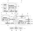
図10は本発明に係る画像表示装置を構成要素とするX線CT画像診断表示システムの第4の実施形態を示す構成図である。  FIG. 10 is a configuration diagram showing a fourth embodiment of an X-ray CT image diagnostic display system including the image display device according to the present invention as a component.

図10に示された、X線CT画像診断表示システム30Cでは、画像表示装置34Cに第1の表示制御部90および第2の表示制御部91を付加した構成および各構成要素の詳細機能が図1に示すX線CT画像診断表示システム30と相違する。他の構成および作用については図1に示すX線CT画像診断表示システム30と実質的に異ならないため同一の構成については同符号を付して説明を省略する。  In the X-ray CT imagediagnostic display system 30C shown in FIG. 10, the configuration in which the firstdisplay control unit 90 and the second display control unit 91 are added to theimage display device 34C and the detailed functions of each component are illustrated. 1 is different from the X-ray CT imagediagnostic display system 30 shown in FIG. Since other configurations and operations are not substantially different from those of the X-ray CT imagediagnostic display system 30 shown in FIG. 1, the same components are denoted by the same reference numerals and description thereof is omitted.

すなわちX線CT画像診断表示システム30Cの画像表示装置34Cには、図1に示す画像表示装置34の構成要素に加え、第1の表示制御部90および第2の表示制御部91が設けられる。  That is, theimage display device 34C of the X-ray CT imagediagnostic display system 30C is provided with a firstdisplay control unit 90 and a second display control unit 91 in addition to the components of theimage display device 34 shown in FIG.

また、MPR画像作成部58には、図1に示すMPR画像作成部58の機能と同等の機能に加え、入力部53から表示部54に表示されるMPR画像の拡大指示あるいは縮小指示等の拡大率変更指示を受けた場合に、入力部53から受けた拡大率変更指示に従ってMPR画像データを作成する機能と、第1の表示制御部90および第2の表示制御部91から受けたMPR画像データの作成指示に従って、所望の方向からのMPR画像データを所望の拡大率で作成する機能とが備えられる。そして、MPR画像作成部58において作成されたMPR画像データは、第1の表示制御部90および第2の表示制御部91に与えられる。  In addition, the MPRimage creation unit 58 has a function equivalent to the function of the MPRimage creation unit 58 shown in FIG. 1 and an enlargement instruction such as an enlargement instruction or reduction instruction of the MPR image displayed on thedisplay unit 54 from theinput part 53. A function of creating MPR image data in accordance with an enlargement rate change instruction received from theinput unit 53 when receiving a rate change instruction, and MPR image data received from the firstdisplay control unit 90 and the second display control unit 91 And a function of creating MPR image data from a desired direction at a desired magnification. The MPR image data created by the MPRimage creation unit 58 is given to the firstdisplay control unit 90 and the second display control unit 91.

第1の表示制御部90は、MPR画像作成部58から受けたMPR画像データを表示部54に与えることにより、MPR画像を表示部54に表示させる機能と、任意方向、例えば3方向のMPR画像を表示させる断面観察画面の表示指示を入力部53から受けた場合に、MPR画像のアキシャル断面方向の横幅が、MPR画像を表示部54に表示させるための表示枠の横幅よりも大きいか否かを判定する機能とを有する。さらに、第1の表示制御部90は、判定結果を第2の表示制御部91に与えるとともに、表示部54に表示されたコロナル画像およびサジタル画像の一方または双方に断面観察画面の表示枠の縦方向(上限幅方向の)の位置を示す線分等の図形や記号を重ねて表示させるための画像情報を作成して表示部54に与える機能を有する。  The firstdisplay control unit 90 provides MPR image data received from the MPRimage creation unit 58 to thedisplay unit 54, thereby displaying the MPR image on thedisplay unit 54, and an MPR image in any direction, for example, three directions. Whether the horizontal width in the axial cross-sectional direction of the MPR image is larger than the horizontal width of the display frame for displaying the MPR image on thedisplay unit 54 when the display instruction of the cross-section observation screen for displaying the image is received from theinput unit 53 And a function of determining Further, the firstdisplay control unit 90 gives the determination result to the second display control unit 91, and the vertical display frame of the cross-section observation screen is displayed on one or both of the coronal image and the sagittal image displayed on thedisplay unit 54. It has a function of creating image information for overlaying and displaying graphics and symbols such as line segments indicating the position in the direction (in the upper limit width direction) and giving it to thedisplay unit 54.

さらに、第1の表示制御部90には、断面観察画面が表示部54に表示されている状態で、入力部53の操作により断面観察画面上に表示されたMPR画像の領域中心の変更指示を受けた場合には、変更後の領域中心の位置を中心として任意方向のMPR画像データを作成するようにMPR画像作成部58に指示を与える機能が備えられる。そして、第1の表示制御部90は、マウス等の入力部53により、断面観察画面上に表示されたMPR画像の領域中心の変更指示を容易に変更できるようにコロナル画像またはサジタル画像にスクロール可能な図形を重ねて表示させるための画像情報を作成して表示部54に与えることができるように構成される。  Further, the firstdisplay control unit 90 is instructed to change the area center of the MPR image displayed on the cross-sectional observation screen by the operation of theinput unit 53 in a state where the cross-sectional observation screen is displayed on thedisplay unit 54. When received, a function is provided to give an instruction to the MPRimage creation unit 58 so as to create MPR image data in an arbitrary direction centering on the position of the changed region center. The firstdisplay control unit 90 can be scrolled to a coronal image or a sagittal image so that an instruction to change the area center of the MPR image displayed on the cross-section observation screen can be easily changed by theinput unit 53 such as a mouse. It is configured so that image information for displaying and displaying various figures can be created and given to thedisplay unit 54.

第2の表示制御部91は、MPR画像を表示させるための表示枠の横幅よりもMPR画像の横幅が大きいと判定された旨の判定結果を第1の表示制御部90から受けた場合には、例えば、そのままの拡大率でMPR画像が表示された表示枠の横幅と同じ横幅の指定方向のMPR画像データを、指定された表示位置を中心として作成するようにMPR画像作成部58に指示を与える機能と、指示に従ってMPR画像作成部58において作成された各MPR画像データを構成要素とする断面観察画面情報を表示部54に与えることにより断面観察画面を表示させる機能とを有する。  When the second display control unit 91 receives a determination result from the firstdisplay control unit 90 that it is determined that the width of the MPR image is larger than the width of the display frame for displaying the MPR image. For example, the MPRimage creation unit 58 is instructed to create MPR image data in the designated direction having the same width as the width of the display frame on which the MPR image is displayed with the enlargement ratio as it is, centering on the designated display position. And a function of displaying a cross-section observation screen by giving thedisplay section 54 cross-section observation screen information having each MPR image data created in the MPRimage creation section 58 in accordance with an instruction as a constituent element.

また、逆に、第2の表示制御部91には、MPR画像を表示させるための表示枠の横幅よりもMPR画像の横幅が小さいと判定された旨の判定結果を第1の表示制御部90から受けた場合に、任意方向の各MPR画像の横幅が断面観察画面におけるMPR画像の表示枠の幅となるように拡大率を調整して各MPR画像データを作成するようにMPR画像作成部58に指示を与える機能と、指示に従ってMPR画像作成部58において作成された各MPR画像データを構成要素とする断面観察画面情報を表示部54に与えることにより断面観察画面を表示させる機能とを有する。  Conversely, the second display control unit 91 displays a determination result indicating that the horizontal width of the MPR image is smaller than the horizontal width of the display frame for displaying the MPR image as the firstdisplay control unit 90. The MPRimage creation unit 58 adjusts the enlargement ratio so that the width of each MPR image in any direction becomes the width of the display frame of the MPR image on the cross-sectional observation screen. And a function of displaying a cross-sectional observation screen by giving thedisplay unit 54 cross-section observation screen information including each MPR image data created in the MPRimage creation unit 58 according to the instruction.

次に画像表示装置34Cの動作および作用について説明する。  Next, the operation and action of theimage display device 34C will be described.

画像表示装置34Cでは、図2と同等な流れにより、薄スライス画像データからアキシャル画像データが作成されて表示される。ただし、図2のステップS3において、MPR画像を表示部54に表示させた後、MPR画像の拡大率の変更や、補助的な画面として断面観察画面を表示させることができる。  In theimage display device 34C, axial image data is created from thin slice image data and displayed in the same flow as in FIG. However, in step S3 in FIG. 2, after the MPR image is displayed on thedisplay unit 54, the magnification of the MPR image can be changed, or the cross-sectional observation screen can be displayed as an auxiliary screen.

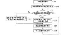
図11は、図10に示す画像表示装置34Cにおいて、断面観察画面を表示部54に表示させる際の流れを示すフローチャートであり、図中Sに数字を付した符号はフローチャートの各ステップを示す。  FIG. 11 is a flowchart showing a flow when the cross-section observation screen is displayed on thedisplay unit 54 in theimage display device 34C shown in FIG. 10, and the reference numerals with numerals in the figure indicate each step of the flowchart.

まず、ステップS3においてMPR画像が表示部54に表示される。  First, an MPR image is displayed on thedisplay unit 54 in step S3.

次に、ステップS30において、入力部53から断面観察画面の表示指示が第1の表示制御部90に入力される。  Next, in step S <b> 30, a display instruction for a cross-section observation screen is input from theinput unit 53 to the firstdisplay control unit 90.

次に、ステップS31において、第1の表示制御部90は、MPR画像のアキシャル断面方向の横幅が、MPR画像を表示部54に表示させるための表示枠の横幅よりも大きいか否かを判定する。  Next, in step S31, the firstdisplay control unit 90 determines whether or not the horizontal width of the MPR image in the axial sectional direction is larger than the horizontal width of the display frame for displaying the MPR image on thedisplay unit 54. .

図12は、図10に示す画像表示装置34Cの表示部54に表示されるMPR画像の横幅と表示枠の横幅との関係を説明する図である。  FIG. 12 is a diagram for explaining the relationship between the horizontal width of the MPR image displayed on thedisplay unit 54 of theimage display device 34C shown in FIG. 10 and the horizontal width of the display frame.

図12に示すように表示部54には、コロナル画像の表示枠100、サジタル画像の表示枠101およびアキシャル画像の表示枠102が表示され、コロナル画像の表示枠100、サジタル画像の表示枠101およびアキシャル画像の表示枠102の内側にそれぞれコロナル画像、サジタル画像およびアキシャル画像が表示される。一般にコロナル画像およびサジタル画像は縦長であるため、コロナル画像の表示枠100およびサジタル画像の表示枠101も縦長とされる。  As shown in FIG. 12, thedisplay unit 54 displays a coronalimage display frame 100, a sagittalimage display frame 101, and an axialimage display frame 102, and a coronalimage display frame 100, a sagittalimage display frame 101, and A coronal image, a sagittal image, and an axial image are displayed inside the axialimage display frame 102, respectively. Since coronal images and sagittal images are generally vertically long, the coronalimage display frame 100 and the sagittalimage display frame 101 are also vertically long.

そして、第1の表示制御部90は、例えばコロナル画像の横幅X1が、コロナル画像の表示枠100の横幅X2よりも大きいか否かを判定する。図12では、コロナル画像の横幅X1が、コロナル画像の表示枠100の横幅X2よりも小さい場合の例を示す。また、コロナル画像には、例えば断面観察画面にコロナル画像を表示させた場合の表示枠の位置を示す実線103と中心位置を示す三角記号104および点線105が表示される。  Then, for example, the firstdisplay control unit 90 determines whether or not the horizontal width X1 of the coronal image is larger than the horizontal width X2 of thedisplay frame 100 of the coronal image. FIG. 12 shows an example in which the horizontal width X1 of the coronal image is smaller than the horizontal width X2 of thedisplay frame 100 of the coronal image. Further, in the coronal image, for example, asolid line 103 indicating the position of the display frame when the coronal image is displayed on the cross-sectional observation screen, atriangular symbol 104 indicating the center position, and adotted line 105 are displayed.

そして、第1の表示制御部90は、MPR画像の横幅が、MPR画像の表示枠の横幅よりも大きいか否かの判定結果を第2の表示制御部91に与える。  Then, the firstdisplay control unit 90 gives the second display control unit 91 a determination result as to whether or not the horizontal width of the MPR image is larger than the horizontal width of the display frame of the MPR image.

次に、ステップS32において、MPR画像の横幅が、MPR画像の表示枠の横幅よりも大きい場合には、第2の表示制御部91は、例えば、同一の拡大率でMPR画像が表示された表示枠の縦横幅と同じ縦横幅の4方向のMPR画像データを、指定された表示位置を中心として作成するようにMPR画像作成部58に指示を与える。そして、MPR画像作成部58は、指示に従って断面観察画面の表示に用いるためのMPR画像データを作成する。  Next, when the horizontal width of the MPR image is larger than the horizontal width of the display frame of the MPR image in step S32, the second display control unit 91 displays the MPR image displayed at the same magnification, for example. The MPRimage creation unit 58 is instructed to create MPR image data in four directions having the same height and width as the frame, centering on the designated display position. Then, the MPRimage creation unit 58 creates MPR image data to be used for displaying the cross-section observation screen according to the instruction.

一方、ステップS33において、MPR画像の横幅が、MPR画像の表示枠の横幅よりも小さい場合には、第2の表示制御部91は、例えば、4方向の各MPR画像の横幅が断面観察画面におけるMPR画像の表示枠の幅となるように拡大率を調整して各MPR画像データを作成するようにMPR画像作成部58に指示を与える。そして、MPR画像作成部58は、指示に従って断面観察画面の表示に用いるためのMPR画像データを作成する。  On the other hand, when the horizontal width of the MPR image is smaller than the horizontal width of the display frame of the MPR image in step S33, the second display control unit 91 determines that the horizontal width of each MPR image in four directions is, for example, on the cross-sectional observation screen. An instruction is given to the MPRimage creation unit 58 so as to create each MPR image data by adjusting the enlargement ratio so as to be the width of the display frame of the MPR image. Then, the MPRimage creation unit 58 creates MPR image data to be used for displaying the cross-section observation screen according to the instruction.

次に、ステップS34において、MPR画像作成部58は、各MPR画像データを第2の表示制御部91に与え、第2の表示制御部91は各MPR画像データを構成要素とする断面観察画面情報を表示部54に与えることにより断面観察画面を表示させる。  Next, in step S34, the MPRimage creation unit 58 gives each MPR image data to the second display control unit 91, and the second display control unit 91 uses the MPR image data as a constituent element for cross-sectional observation screen information. Is given to thedisplay unit 54 to display a cross-section observation screen.

図13は、図10に示す画像表示装置34Cの表示部54に表示される断面観察画面の一例を示す図である。  FIG. 13 is a diagram showing an example of a cross-section observation screen displayed on thedisplay unit 54 of theimage display device 34C shown in FIG.

図13に示すように、断面観察画面には、コロナル画像D3、サジタル画像D4、アキシャル画像D5、オブリーク画像D6が表示される。また、サジタル画像D4上には、オブリーク画像D6の断面方向が点線の線分により表示されている。  As shown in FIG. 13, a coronal image D3, a sagittal image D4, an axial image D5, and an oblique image D6 are displayed on the cross-section observation screen. On the sagittal image D4, the cross-sectional direction of the oblique image D6 is displayed as a dotted line segment.

この状態で、入力部53の操作により、断面観察画面に表示されたコロナル画像D3、サジタル画像D4、アキシャル画像D5、オブリーク画像D6の中心位置を変更することもできる。  In this state, the center position of the coronal image D3, the sagittal image D4, the axial image D5, and the oblique image D6 displayed on the cross-section observation screen can be changed by operating theinput unit 53.

その場合には、ステップS35において、マウス等の入力部53から断面観察画面に表示されたMPR画像の中心位置の変更指示が第1の表示制御部90に入力される。このとき、第1の表示制御部90から表示部54に与えられて表示されたコロナル画像を参照しつつ、断面観察画像の中心位置を設定するための図形をスクロールすることにより、MPR画像の中心位置の変更指示を第1の表示制御部90に入力することができる。  In that case, an instruction to change the center position of the MPR image displayed on the cross-section observation screen is input to the firstdisplay control unit 90 from theinput unit 53 such as a mouse in step S35. At this time, the center of the MPR image is scrolled by scrolling the figure for setting the center position of the cross-sectional observation image while referring to the coronal image given to thedisplay unit 54 from the firstdisplay control unit 90 and displayed. A position change instruction can be input to the firstdisplay control unit 90.

図14は、図10に示す画像表示装置34Cの表示部54に表示されるコロナル画像を介して断面観察画面に表示されるMPR画像の中心位置を変更する場合の例を示す図である。  FIG. 14 is a diagram showing an example of changing the center position of the MPR image displayed on the cross-sectional observation screen via the coronal image displayed on thedisplay unit 54 of theimage display device 34C shown in FIG.

図14に示すように表示部54に表示されたコロナル画像には、断面観察画像の表示枠を示す実線103の線分と、中心位置を示す点線105の線分が表示される。また、中心位置を変更するための三角記号104および矢印記号106が重ねて表示される。尚、図14は、MPR画像の横幅が、MPR画像の表示枠の横幅よりも大きい場合の例を示す。また、このとき、断面観察画像の表示枠を示す実線103間の範囲X3が断面観察画面上におけるコロナル画像の表示範囲X3となる。  As shown in FIG. 14, in the coronal image displayed on thedisplay unit 54, asolid line 103 indicating the display frame of the cross-sectional observation image and adotted line 105 indicating the center position are displayed. Further, atriangle symbol 104 and anarrow symbol 106 for changing the center position are displayed in an overlapping manner. FIG. 14 shows an example in which the horizontal width of the MPR image is larger than the horizontal width of the display frame of the MPR image. At this time, the range X3 between thesolid lines 103 indicating the display frame of the cross-section observation image is the display range X3 of the coronal image on the cross-section observation screen.

そして、マウス等の入力部53の操作により、三角記号104や矢印記号106をスクロールすると、コロナル画像の表示範囲および中心位置の変更指示が第1の表示制御部90に入力せしめられる。このため、第1の表示制御部90からMPR画像作成部58に、変更後の領域中心の位置を中心として所望のMPR画像データを作成するように指示が与えられる。  When thetriangular symbol 104 or thearrow symbol 106 is scrolled by operating theinput unit 53 such as a mouse, the firstdisplay control unit 90 is instructed to change the display range and center position of the coronal image. For this reason, the firstdisplay control unit 90 gives an instruction to the MPRimage creation unit 58 to create desired MPR image data around the position of the changed region center.

そして、再びステップS32において、変更後のMPR画像データが再作成され、ステップS33において断面観察画面に再作成されたコロナル画像等のMPR画像が表示される。  Then, in step S32 again, the changed MPR image data is re-created, and the MPR image such as the re-created coronal image is displayed on the cross-section observation screen in step S33.

つまり、以上の画像表示装置34Cは、コロナル画像やサジタル画像等のMPR画像を所望の拡大率で表示部54に表示できるようにし、かつ表示部54に向かってMPR画像の横方向の幅が表示枠の横幅を超えた場合にアスペクト比が1:1のMPR画像を別途あるいは切換えて表示部54に表示できるように構成したものである。  That is, theimage display device 34C described above can display an MPR image such as a coronal image or a sagittal image on thedisplay unit 54 at a desired magnification, and the width of the MPR image in the horizontal direction is displayed toward thedisplay unit 54. When the width of the frame is exceeded, an MPR image having an aspect ratio of 1: 1 can be displayed on thedisplay unit 54 separately or by switching.

このため、画像表示装置34Cによれば、コロナル画像やサジタル画像の横幅が表示枠の横幅よりも大きく縦長である場合であっても、コロナル画像やサジタル画像を観察対象となる範囲内で拡大表示させることができる。これにより、縦長のコロナル画像やサジタル画像を参照しながら、断面観察画面に表示されるMPR画像の範囲を自由に変更しつつ、連続的に観察を行うことができる。  For this reason, according to theimage display device 34C, even when the horizontal width of the coronal image or the sagittal image is larger than the horizontal width of the display frame, the coronal image or the sagittal image is enlarged and displayed within the range to be observed. Can be made. Accordingly, it is possible to perform continuous observation while freely changing the range of the MPR image displayed on the cross-sectional observation screen while referring to the vertically long coronal image or sagittal image.

尚、以上の各実施形態におけるX線CT画像診断表示システム30、30A、30B、30Cや画像表示装置34、34A、34B、34Cを互いに組み合わせて構成してもよく、一部の構成要素や機能を省略して構成してもよい。  The X-ray CT imagediagnostic display systems 30, 30A, 30B, and 30C and theimage display devices 34, 34A, 34B, and 34C in the above embodiments may be combined with each other, and some components and functions May be omitted.

また、表示させるMPR画像をアキシャル画像としたが、アキシャル断面方向以外の他の方向(第1の方向)のMPR画像を表示させるために第1の方向と異なる第2の方向のMPR画像を参照用に用いてもよい。  In addition, although the MPR image to be displayed is an axial image, the MPR image in a second direction different from the first direction is referred to display an MPR image in a direction other than the axial cross-sectional direction (first direction). It may be used for

本発明に係る画像表示装置を構成要素とするX線CT画像診断表示システムの第1の実施形態を示す構成図。BRIEF DESCRIPTION OF THE DRAWINGS The block diagram which shows 1st Embodiment of the X-ray CT image diagnostic display system which uses the image display apparatus which concerns on this invention as a component.図1に示す画像表示装置において、観察範囲および表示枚数を指定してアキシャル画像を表示させる際の流れを示すフローチャート。The flowchart which shows the flow at the time of displaying an axial image by designating an observation range and the number of displayed sheets in the image display apparatus shown in FIG.図1の画像表示装置における表示部に表示される画面の一例を示す図。The figure which shows an example of the screen displayed on the display part in the image display apparatus of FIG.図1に示す画像表示装置のスラブ画像生成部によるスラブ画像データの作成方法の一例を説明する図。The figure explaining an example of the production method of the slab image data by the slab image production | generation part of the image display apparatus shown in FIG.本発明に係る画像表示装置を構成要素とするX線CT画像診断表示システムの第2の実施形態を示す構成図。The block diagram which shows 2nd Embodiment of the X-ray CT image diagnostic display system which uses the image display apparatus which concerns on this invention as a component.図5に示す画像表示装置において、観察部位を指定してアキシャル画像を表示させる際の流れを示すフローチャート。The flowchart which shows the flow at the time of specifying an observation site | part and displaying an axial image in the image display apparatus shown in FIG.図5に示す画像表示装置のスライス厚保存部に保存されるデータの一例を示す図。The figure which shows an example of the data preserve | saved at the slice thickness preservation | save part of the image display apparatus shown in FIG.本発明に係る画像表示装置を構成要素とするX線CT画像診断表示システムの第3の実施形態を示す構成図。The block diagram which shows 3rd Embodiment of the X-ray CT image diagnostic display system which uses the image display apparatus which concerns on this invention as a component.図8に示す画像表示装置において、表示条件を自動的に設定してアキシャル画像を表示させる際の流れを示すフローチャート。The flowchart which shows the flow at the time of displaying an axial image by setting a display condition automatically in the image display apparatus shown in FIG.本発明に係る画像表示装置を構成要素とするX線CT画像診断表示システムの第4の実施形態を示す構成図。The block diagram which shows 4th Embodiment of the X-ray CT image diagnostic display system which uses the image display apparatus which concerns on this invention as a component.図10に示す画像表示装置において、断面観察画面を表示部に表示させる際の流れを示すフローチャート。The flowchart which shows the flow at the time of displaying a cross-section observation screen on a display part in the image display apparatus shown in FIG.図10に示す画像表示装置の表示部に表示されるMPR画像の横幅と表示枠の横幅との関係を説明する図。The figure explaining the relationship between the horizontal width of the MPR image displayed on the display part of the image display apparatus shown in FIG. 10, and the horizontal width of a display frame.図10に示す画像表示装置の表示部に表示される断面観察画面の一例を示す図。The figure which shows an example of the cross-section observation screen displayed on the display part of the image display apparatus shown in FIG.図10に示す画像表示装置の表示部に表示されるコロナル画像を介して断面観察画面に表示されるMPR画像の中心位置を変更する場合の例を示す図。The figure which shows the example in the case of changing the center position of the MPR image displayed on a cross-section observation screen via the coronal image displayed on the display part of the image display apparatus shown in FIG.従来のX線CT画像診断表示システムの構成図。The block diagram of the conventional X-ray CT image diagnostic display system.

符号の説明Explanation of symbols

30、30A、30B、30C X線CT画像診断表示システム
31 X線CT装置
32 3次元ワークステーション(3D−WS)
33 画像サーバ
34、34A、34B、34C 画像表示装置
35 ネットワーク
36 検出器
37 生データ保存部
38 画像再構成部
39 再構成画像保存部
40 3D画像作成部
41 通信部
42 通信部
43 3D画像保存部
44 3D画像作成部
45 表示部
46 通信部
47 画像保存部
48 記録部
49 管理部
50 記録媒体
51 通信部
52 取得画像保存部
53 入力部
54 表示部
55 観察範囲指定部
56 画像枚数指定部
57 スラブ画像生成部
58 MPR画像作成部
60 バー
61 スクロールバー
70 画像再構成指示部
71 スライス厚保存部
80 表示条件保存部
81 表示条件検索部
82 レポートサーバ
83 レポート検索部
84 関連画像検索部
85 画像条件抽出部
90 第1の表示制御部
91 第2の表示制御部
100 コロナル画像の表示枠
101 サジタル画像の表示枠
102 アキシャル画像の表示枠
103 実線
104 三角記号
105 点線
106 矢印記号
30, 30A, 30B, 30C X-ray CT imagediagnostic display system 31X-ray CT apparatus 32 3D workstation (3D-WS)
33Image servers 34, 34A, 34B, 34CImage display device 35Network 36Detector 37 Rawdata storage unit 38Image reconstruction unit 39 Reconstructedimage storage unit 40 3Dimage creation unit 41Communication unit 42Communication unit 43 3Dimage storage unit 44 3Dimage creation unit 45Display unit 46Communication unit 47Image storage unit 48Recording unit 49Management unit 50Recording medium 51Communication unit 52 Acquiredimage storage unit 53Input unit 54Display unit 55 Observationrange specification unit 56 Imagenumber specification unit 57 SlabImage generation unit 58 MPRimage creation unit 60Bar 61Scroll bar 70 Imagereconstruction instruction unit 71 Slicethickness storage unit 80 Displaycondition storage unit 81 Displaycondition search unit 82Report server 83Report search unit 84 Relatedimage search unit 85 Imagecondition extraction Unit 90 first display control unit 91 seconddisplay control unit 100 coronal image display frame 1 1display frame 103 of thedisplay frame 102 the axial image of a sagittal image solid 104triangular symbols 105 dotted 106 arrow symbol

Claims (14)

Translated fromJapanese
入力部および表示部を備えた画像表示装置において、
参照画像を前記表示部に表示させる参照画像表示手段と、
前記入力部から取得した指示情報および前記参照画像に基て断面画像データ観察範囲を指定する観察範囲指定手段と、
前記断面画像データ厚さを指定する断面厚指定手段と、
所定値以下のスライス厚の複数のスライス画像データが前記保存部に保存されていると判断される場合に、前記観察範囲に含まれる前記所定値以下のスライス厚の複数のスライス画像データを用いて、前記指定された厚さの断面画像データが前記観察範囲内に生成されるように所要の厚さのスラブ画像データを生成し、前記生成されたスラブ画像データを前記表示に与えることにより前記断面画像データを表示させるスラブ画像生成手段と、
各種のスライス厚のスライス画像データを保存可能な保存部に、前記所定値以下のスライス厚のスライス画像データが保存されていないと判断される場合に、前記所定値以下のスライス厚のスライス画像データの再構成指示を画像再構成手段に送信する画像再構成指示手段と、
を有することを特徴とする画像表示装置。
In an image display device including an input unit and a display unit,
Reference image displaymeans for displaying a reference image on the displayunit ;
An observation range specifyingmeans for specifying theobservation range of thecross-sectional plane imagedata have basedDzu the instruction information and the reference image acquired from the input unit,
Across-sectional thickness specifyingmeans for specifying thethickness ofthe cross-sectional imagedata,
When it is determined that a plurality of slice image data having a slice thickness of a predetermined value or less is stored in the storage unit,the plurality of slice image data havinga slice thickness of the predetermined value or less included in theobservation range is used.the by cross-sectional image data ofthe designatedthickness to produce the required thickness of the slab image data to be generated withinthe observation range, providingthe generated slab image data on the displayunit Slab image generationmeans for displaying cross-sectional imagedata ;
When it is determined that slice image data with a slice thickness equal to or less than the predetermined value is not stored in a storage unit capable of storing slice image data with various slice thicknesses, slice image data with a slice thickness less than the predetermined value Image reconstruction instruction means for transmitting the reconstruction instruction to the image reconstruction means;
An image display device comprising:
前記スラブ画像生成手段は、前記指定された厚さのアキシャル画像データが前記観察範囲内に生成されるように前記スラブ画像データを生成し、前記生成されたスラブ画像データを前記表示部に与えることにより前記アキシャル画像を表示させるように構成されることを特徴とする請求項記載の画像表示装置。The slab image generatingmeans, the axial image data ofthe designatedthickness generates the slab image data to be generated within theobservation range, providingthe generated slab image data on the display unit The image display device according to claim1 , wherein the image display device is configured to display the axial image. 前記参照画像表示手段は、複数のスライス画像データを取得して断面変換処理を行うことにより断面画像データを生成し、前記生成された断面画像データを前記表示部に与えることにより、前記断面画像とは異なる方向の断面画像データを前記参照画像として前記表示部に表示させるように構成されることを特徴とする請求項記載の画像表示装置。The reference image displayunit acquires a plurality of slice image datato generate the cross sectional image data by performing the cross-section conversion processingby providing a cross-sectional image datathe generated on the display unit,the cross-sectional image the image display apparatus according to claim1, characterized in that it is configured to cross-sectional imagedata of the directiontowards that different so as to display on the display unit as the referenceimage. 前記参照画像表示手段は、前記参照画像としてスキャノ画像を前記表示部に表示させるように構成されることを特徴とする請求項記載の画像表示装置。The reference image displaymeans, the image display apparatus according to claim1, characterized in that it is configured to scanogram image as the reference image to be displayed on the display unit. 前記観察範囲指定手段は、前記観察範囲を指定するための画像データを前記表示部に与えて表示させる一方、前記入力部によるスクロールによって、前記観察範囲を指定できるように構成されることを特徴とする請求項記載の画像表示装置。The observation range designatingunit is configured so that image data for designating theobservation range is given to the display unit and displayed, and theobservation range can be designated by scrolling with the input unit. The image display device according to claim1 . 前記断面厚指定手段は、前記断面画像データの厚さを指定するための画像データを前記表示部に与えて表示させる一方、前記入力部によるスクロールによって、前記断面画像データの厚さを指定できるように構成されることを特徴とする請求項記載の画像表示装置。Thecross-sectional thickness designatingmeans givesimage data for designatingthe thickness of the cross-sectional image data to the display unit for display, whilethe thickness of the cross-sectional image data can be designated by scrolling by the input unit. The image display device according to claim1 , wherein the image display device is configured as follows.前記画像再構成指示手段は、前記所定値としての前記スラブ画像データの1/2の厚さ以下のスライス厚のスライス画像データが前記保存部に保存されていないと判断される場合に、前記再構成指示を前記画像再構成手段に送信することを特徴とする請求項記載の画像表示装置。Wherein the image reconfiguration instruction unit, when half of the thicknessbelow the slice thickness of the slice image data of the slab image dataas the predetermined valueis determined not to be saved beforeKiho presence section, the image display apparatus according to claim1, wherein thebenzalkonium to transmitthe reconfiguration instruction tosaid image reconstructionmeans.前記画像再構成指示手段は、前記再構成指示をX線CT装置の前記画像再構成手段に送信することを特徴とする請求項記載の画像表示装置。The image reconstruction instructing means, the image display apparatus according to claim1, wherein thebenzalkonium to transmitthe reconfiguration instruction tothe image reconstructionunit of the X-ray CT apparatus.前記画像再構成指示手段は、前記所定値としての前記スラブ画像データの1/2の厚さ以下のスライス厚のスライス画像データが前記保存部に保存されていないと判断される場合に、前記再構成指示をX線CT装置の前記画像再構成手段に送信することを特徴とする請求項記載の画像表示装置。Wherein the image reconfiguration instruction unit, when half of the thicknessbelow the slice thickness of the slice image data of the slab image dataas the predetermined valueis determined not to be saved beforeKiho presence section, the image display apparatus according to claim1, wherein thebenzalkonium to transmitthe reconfiguration instruction tothe image reconstructionunit of the X-ray CT apparatus.記画像再構成手段により再構成されたスライス画像データを受信する画像データ受信手段をさらに有することを特徴とする請求項記載の画像表示装置。The image display apparatus according to claim1, furthercomprising an image data receivingmeans for receiving the slice image data reconstructed by thepre-Symbol image reconstructionmeans.前記画像再構成指示手段は、前記所定値としての前記スラブ画像データの1/2の厚さ以下のスライス厚のスライス画像データが前記保存部に保存されていないと判断される場合に、前記再構成指示を前記画像再構成手段に送信
前記画像再構成手段により再構成されたスライス画像データを受信する画像データ受信手段をさらに有することを特徴とする請求項記載の画像表示装置。
Wherein the image reconfiguration instruction unit, when half of the thicknessbelow the slice thickness of the slice image data of the slab image dataas the predetermined valueis determined not to be saved beforeKiho presence section,transmittingthe reconfiguration instruction tosaid image reconstructionmeans,
The image display apparatus according to claim1, furthercomprising an image data receivingmeans for receiving the slice image data reconstructed by the image reconstructionmeans.
前記画像再構成指示手段は、前記再構成指示および前記再構成指示に従って再構成されるスライス画像データの送信先を前記画像再構成手段に送信することを特徴とする請求項記載の画像表示装置。The image reconstruction instructing means, an image of claim1, wherein thebenzalkonium be transmitted to send the reconstructed slice image data tothe image reconstructionunit according tothe reconfiguration instruction and the reconfiguration instruction Display device.前記画像再構成指示手段は、前記所定値としての前記スラブ画像データの1/2の厚さ以下のスライス厚のスライス画像データが前記保存部に保存されていない場合に、前記再構成指示および前記再構成指示に従って再構成されるスライス画像データの送信先を前記画像再構成手段に送信することを特徴とする請求項記載の画像表示装置。Wherein the image reconfiguration instruction unit, when half of the thicknessbelow the slice thickness of the slice image data of the slab image dataas the predetermined value is not saved beforeKiho presence section,the reconfiguration instruction and the image display apparatus according to claim1, wherein the destination of the reconstructed slice image data in accordance with the reconfiguration instruction and wherein theTurkey be transmitted tosaid image reconstructionmeans. 被検体の観察部位と前記スラブ画像データの厚さとを関連付けて保存するスラブ厚保存部をさらに有し
前記断面厚指定手段は、前記入力部から前記観察部位の指示を受けた場合に、前記スラブ厚保存部を参照し、前記観察部位に関連付けられた前記スラブ画像データの厚さを前記断面画像データの厚さとして指定するように構成されることを特徴とする請求項記載の画像表示装置。
Furthercomprising aslab thickness storage unit that stores in association with the thickness ofthe slab image data and the observed region of the subject,
Saidcross-sectional thickness designatingmeans, when receiving the instruction of the observed region from the input unit, by referring to theslab thickness storage unit,wherein the thickness of the slab image data associated with the observation region cross-sectional imagedata The image display device according to claim1 , wherein the image display device is configured to be designated asa thickness of the image.
JP2006083406A2005-04-062006-03-24 Image display deviceExpired - Fee RelatedJP5038643B2 (en)

Priority Applications (1)

Application NumberPriority DateFiling DateTitle
JP2006083406AJP5038643B2 (en)2005-04-062006-03-24 Image display device

Applications Claiming Priority (3)

Application NumberPriority DateFiling DateTitle
JP20051098422005-04-06
JP2006083406AJP5038643B2 (en)2005-04-062006-03-24 Image display device

Publications (2)

Publication NumberPublication Date
JP2006312026A JP2006312026A (en)2006-11-16
JP5038643B2true JP5038643B2 (en)2012-10-03

Family

ID=37533762

Family Applications (1)

Application NumberTitlePriority DateFiling Date
JP2006083406AExpired - Fee RelatedJP5038643B2 (en)2005-04-062006-03-24 Image display device

Country Status (1)

CountryLink
JP (1)JP5038643B2 (en)

Families Citing this family (27)

* Cited by examiner, † Cited by third party
Publication numberPriority datePublication dateAssigneeTitle
WO2007095330A2 (en)2006-02-152007-08-23Hologic IncBreast biopsy and needle localization using tomosynthesis systems
JP5148094B2 (en)*2006-09-272013-02-20株式会社東芝 Ultrasonic diagnostic apparatus, medical image processing apparatus, and program
JP5566567B2 (en)*2007-03-142014-08-06株式会社東芝 MEDICAL IMAGE DISPLAY DEVICE, MEDICAL IMAGE DISPLAY METHOD, AND MEDICAL IMAGE DIAGNOSIS DEVICE
JP2009022368A (en)*2007-07-172009-02-05Toshiba Corp Medical image observation support system
JP5317453B2 (en)*2007-09-212013-10-16株式会社東芝 Medical image processing device
JP5288815B2 (en)*2008-01-302013-09-11株式会社東芝 Medical image display device and report display device
KR101536926B1 (en)*2008-11-272015-07-15삼성전자주식회사 METHOD AND APPARATUS FOR GENERATING AND RENDERING 3D MODELS IN ELECT
ES2862525T3 (en)2009-10-082021-10-07Hologic Inc Needle Breast Biopsy System and Method of Use
EP2577608B1 (en)*2010-05-272014-07-16Koninklijke Philips N.V.Improved reconstruction for cone-beam computed tomography imaging with off-center flat panel detector
US20120133600A1 (en)2010-11-262012-05-31Hologic, Inc.User interface for medical image review workstation
JP6057922B2 (en)2011-03-082017-01-11ホロジック, インコーポレイテッドHologic, Inc. System and method for dual energy and / or contrast enhanced breast imaging for screening, diagnosis and biopsy
EP2782505B1 (en)2011-11-272020-04-22Hologic, Inc.System and method for generating a 2d image using mammography and/or tomosynthesis image data
JP6240097B2 (en)2012-02-132017-11-29ホロジック インコーポレイティッド How to navigate a tomosynthesis stack using composite image data
US10092358B2 (en)2013-03-152018-10-09Hologic, Inc.Tomosynthesis-guided biopsy apparatus and method
CN105451657A (en)2013-03-152016-03-30霍罗吉克公司System and method for navigating tomosynthesis stack including automatic focusing
EP3060132B1 (en)2013-10-242019-12-04Hologic, Inc.System and method for navigating x-ray guided breast biopsy
JP6506769B2 (en)*2014-02-282019-04-24ホロジック, インコーポレイテッドHologic, Inc. System and method for generating and displaying tomosynthesis image slabs
WO2016117418A1 (en)*2015-01-232016-07-28株式会社日立製作所X-ray ct apparatus and imaging method
EP3423968B1 (en)*2016-03-032021-08-18Koninklijke Philips N.V.Medical image navigation system
EP3600047A1 (en)2017-03-302020-02-05Hologic, Inc.System and method for hierarchical multi-level feature image synthesis and representation
CN110621233B (en)2017-03-302023-12-12豪洛捷公司Method for processing breast tissue image data
EP3600052A1 (en)2017-03-302020-02-05Hologic, Inc.System and method for targeted object enhancement to generate synthetic breast tissue images
WO2018236565A1 (en)2017-06-202018-12-27Hologic, Inc. METHOD AND SYSTEM FOR MEDICAL IMAGING WITH DYNAMIC SELF-LEARNING
WO2020068851A1 (en)2018-09-242020-04-02Hologic, Inc.Breast mapping and abnormality localization
JP7497422B2 (en)*2020-03-162024-06-10富士フイルム株式会社 Image processing device, image display system, operation method and program for image processing device
US12254586B2 (en)2021-10-252025-03-18Hologic, Inc.Auto-focus tool for multimodality image review
WO2023097279A1 (en)2021-11-292023-06-01Hologic, Inc.Systems and methods for correlating objects of interest

Family Cites Families (4)

* Cited by examiner, † Cited by third party
Publication numberPriority datePublication dateAssigneeTitle
JP3730325B2 (en)*1996-08-122006-01-05株式会社東芝 Image display device
JP4597334B2 (en)*2000-09-122010-12-15株式会社日立メディコ Diagnostic imaging equipment
JP4772218B2 (en)*2001-06-212011-09-14ジーイー・メディカル・システムズ・グローバル・テクノロジー・カンパニー・エルエルシー X-ray CT apparatus and program
JP2004188002A (en)*2002-12-122004-07-08Fuji Photo Film Co LtdImage display device

Also Published As

Publication numberPublication date
JP2006312026A (en)2006-11-16

Similar Documents

PublicationPublication DateTitle
JP5038643B2 (en) Image display device
CN1846622B (en)Image display device and image display method
US11372534B2 (en)Image handling and display in x-ray mammography and tomosynthesis
US10452252B2 (en)Image handling and display in X-ray mammography and tomosynthesis
US8397170B2 (en)Medical image display apparatus
US8929627B2 (en)Examination information display device and method
JP4671204B2 (en) Medical image display control apparatus and medical image display control program
JP5305635B2 (en) Medical image display device
JP2006314702A (en) Medical image display device and medical image display method
JP2007087285A (en) Interpretation report creation device and client terminal
JP5592655B2 (en) Image processing device
JP2006262975A (en)Medical image display
JP2005245914A (en) Image processing apparatus, image diagnostic system, and image processing method therefor
JP2018000605A (en)Information processing system, information processing method and program
JP2007006930A (en)Medical image processing method
JP2021002303A (en)Program, system, and method for assisting diagnosis

Legal Events

DateCodeTitleDescription
A621Written request for application examination

Free format text:JAPANESE INTERMEDIATE CODE: A621

Effective date:20090323

A977Report on retrieval

Free format text:JAPANESE INTERMEDIATE CODE: A971007

Effective date:20110511

RD01Notification of change of attorney

Free format text:JAPANESE INTERMEDIATE CODE: A7421

Effective date:20111201

A131Notification of reasons for refusal

Free format text:JAPANESE INTERMEDIATE CODE: A131

Effective date:20120313

A521Request for written amendment filed

Free format text:JAPANESE INTERMEDIATE CODE: A523

Effective date:20120511

TRDDDecision of grant or rejection written
A01Written decision to grant a patent or to grant a registration (utility model)

Free format text:JAPANESE INTERMEDIATE CODE: A01

Effective date:20120612

A01Written decision to grant a patent or to grant a registration (utility model)

Free format text:JAPANESE INTERMEDIATE CODE: A01

A61First payment of annual fees (during grant procedure)

Free format text:JAPANESE INTERMEDIATE CODE: A61

Effective date:20120706

FPAYRenewal fee payment (event date is renewal date of database)

Free format text:PAYMENT UNTIL: 20150713

Year of fee payment:3

R150Certificate of patent or registration of utility model

Ref document number:5038643

Country of ref document:JP

Free format text:JAPANESE INTERMEDIATE CODE: R150

Free format text:JAPANESE INTERMEDIATE CODE: R150

S111Request for change of ownership or part of ownership

Free format text:JAPANESE INTERMEDIATE CODE: R313117

R350Written notification of registration of transfer

Free format text:JAPANESE INTERMEDIATE CODE: R350

S533Written request for registration of change of name

Free format text:JAPANESE INTERMEDIATE CODE: R313533

R350Written notification of registration of transfer

Free format text:JAPANESE INTERMEDIATE CODE: R350

LAPSCancellation because of no payment of annual fees

[8]ページ先頭

©2009-2025 Movatter.jp