JP5038555B2 - Filtration membrane module cleaning apparatus and cleaning method - Google Patents
Filtration membrane module cleaning apparatus and cleaning methodDownload PDFInfo
- Publication number
- JP5038555B2 JP5038555B2JP2000572010AJP2000572010AJP5038555B2JP 5038555 B2JP5038555 B2JP 5038555B2JP 2000572010 AJP2000572010 AJP 2000572010AJP 2000572010 AJP2000572010 AJP 2000572010AJP 5038555 B2JP5038555 B2JP 5038555B2
- Authority
- JP
- Japan
- Prior art keywords
- liquid
- membrane
- bubbles
- membrane module
- hollow fiber
- Prior art date
- Legal status (The legal status is an assumption and is not a legal conclusion. Google has not performed a legal analysis and makes no representation as to the accuracy of the status listed.)
- Expired - Fee Related
Links
Images


Classifications
- B—PERFORMING OPERATIONS; TRANSPORTING
- B01—PHYSICAL OR CHEMICAL PROCESSES OR APPARATUS IN GENERAL
- B01D—SEPARATION
- B01D65/00—Accessories or auxiliary operations, in general, for separation processes or apparatus using semi-permeable membranes
- B01D65/02—Membrane cleaning or sterilisation ; Membrane regeneration
- B01D65/04—Membrane cleaning or sterilisation ; Membrane regeneration with movable bodies, e.g. foam balls
- C—CHEMISTRY; METALLURGY
- C02—TREATMENT OF WATER, WASTE WATER, SEWAGE, OR SLUDGE
- C02F—TREATMENT OF WATER, WASTE WATER, SEWAGE, OR SLUDGE
- C02F3/00—Biological treatment of water, waste water, or sewage
- C02F3/02—Aerobic processes
- C02F3/12—Activated sludge processes
- C02F3/1236—Particular type of activated sludge installations
- C02F3/1268—Membrane bioreactor systems
- C02F3/1273—Submerged membrane bioreactors
- B—PERFORMING OPERATIONS; TRANSPORTING
- B01—PHYSICAL OR CHEMICAL PROCESSES OR APPARATUS IN GENERAL
- B01D—SEPARATION
- B01D63/00—Apparatus in general for separation processes using semi-permeable membranes
- B01D63/02—Hollow fibre modules
- B01D63/033—Specific distribution of fibres within one potting or tube-sheet
- B—PERFORMING OPERATIONS; TRANSPORTING
- B01—PHYSICAL OR CHEMICAL PROCESSES OR APPARATUS IN GENERAL
- B01D—SEPARATION
- B01D65/00—Accessories or auxiliary operations, in general, for separation processes or apparatus using semi-permeable membranes
- B01D65/02—Membrane cleaning or sterilisation ; Membrane regeneration
- B—PERFORMING OPERATIONS; TRANSPORTING
- B01—PHYSICAL OR CHEMICAL PROCESSES OR APPARATUS IN GENERAL
- B01D—SEPARATION
- B01D65/00—Accessories or auxiliary operations, in general, for separation processes or apparatus using semi-permeable membranes
- B01D65/08—Prevention of membrane fouling or of concentration polarisation
- B—PERFORMING OPERATIONS; TRANSPORTING
- B01—PHYSICAL OR CHEMICAL PROCESSES OR APPARATUS IN GENERAL
- B01D—SEPARATION
- B01D2313/00—Details relating to membrane modules or apparatus
- B01D2313/14—Specific spacers
- B—PERFORMING OPERATIONS; TRANSPORTING
- B01—PHYSICAL OR CHEMICAL PROCESSES OR APPARATUS IN GENERAL
- B01D—SEPARATION
- B01D2321/00—Details relating to membrane cleaning, regeneration, sterilization or to the prevention of fouling
- B01D2321/04—Backflushing
- B—PERFORMING OPERATIONS; TRANSPORTING
- B01—PHYSICAL OR CHEMICAL PROCESSES OR APPARATUS IN GENERAL
- B01D—SEPARATION
- B01D2321/00—Details relating to membrane cleaning, regeneration, sterilization or to the prevention of fouling
- B01D2321/18—Use of gases
- B01D2321/185—Aeration
- Y—GENERAL TAGGING OF NEW TECHNOLOGICAL DEVELOPMENTS; GENERAL TAGGING OF CROSS-SECTIONAL TECHNOLOGIES SPANNING OVER SEVERAL SECTIONS OF THE IPC; TECHNICAL SUBJECTS COVERED BY FORMER USPC CROSS-REFERENCE ART COLLECTIONS [XRACs] AND DIGESTS
- Y02—TECHNOLOGIES OR APPLICATIONS FOR MITIGATION OR ADAPTATION AGAINST CLIMATE CHANGE
- Y02W—CLIMATE CHANGE MITIGATION TECHNOLOGIES RELATED TO WASTEWATER TREATMENT OR WASTE MANAGEMENT
- Y02W10/00—Technologies for wastewater treatment
- Y02W10/10—Biological treatment of water, waste water, or sewage
Landscapes
- Chemical & Material Sciences (AREA)
- Chemical Kinetics & Catalysis (AREA)
- Life Sciences & Earth Sciences (AREA)
- Biodiversity & Conservation Biology (AREA)
- Microbiology (AREA)
- Hydrology & Water Resources (AREA)
- Engineering & Computer Science (AREA)
- Environmental & Geological Engineering (AREA)
- Water Supply & Treatment (AREA)
- Organic Chemistry (AREA)
- Separation Using Semi-Permeable Membranes (AREA)
- Apparatus Associated With Microorganisms And Enzymes (AREA)
Description
Translated fromJapanese【0001】
技術分野
本発明は、ベンチュリー、ジェット等を使用して形成される、気体と液体の混合物を用いて、効率的に膜モジュールを洗浄する装置及びそれに関連する方法に関する。例えば、バイオリアクター内等の、高濃度の懸濁物質(または浮遊固形物)が存在する環境に利用される膜モジュール用に、モジュール内に蓄積した物質(又は固形物)を減らす、数種の改良モジュールの構成を述べる。
【0002】
本発明の背景
汚水処理用膜モジュールの重要性が、急速に拡大している。膜プロセスは第三位の効率的な汚水処理方法して使用され、良質な排出液をもたらし得ることが周知である。しかし、資金及び運転費用によって制限され得る。膜モジュールが大きなフィードタンクに沈められ、膜の濾液側に使用される吸引によって濾液が収集される水中膜プロセス(submerged membrane process)の出現にともない、生物的プロセス及び物理的プロセスを一つの段階に組み合わせた膜バイオリアクターは、よりコンパクト、効率的、経済的であると期待されている。その融通性ゆえに、膜バイオリアクターの大きさは、家庭用(腐敗槽システム)から地域社会及び大規模汚水処理までの範囲に渡り得る。
【0003】
膜濾過プロセスの成功は、効果的かつ効率的な膜洗浄方法の採用に大きく依存する。通常使用される物理的洗浄方法には、浸透液体もしくは気体を用いるバックウォッシュ(逆流、backwash)(バックパルス、バックフラッシュ:backpulse、 backflush)又は液体中で気泡を生ずる気体を用いる膜表面のスクラッビング洗浄又はスコアリング洗い流し洗浄がある。第二のタイプの方法の例は、イシダ他による米国特許第5,192,456号公報(Ishida et al., United States Patent No. 5,192,456)、コート他による米国特許第5,248,424号公報(Cote et al., United States Patent No. 5,248,424)、ヘンショウ他による米国特許第5,639,373号公報および第5,783,083号公報(Henshaw et al., United States Patents No. 5,639,373 and No. 5,783,083)及び我々の国際特許出願国際公開第98/28066号公報(PCT Application No. WO98/28066)に示されている。
【0004】
上述の例では、膜モジュールを浸める液体システム内に、気体の泡(気泡)を形成するために、通常加圧送風機を用いて、気体を注入する(吹き込む)。そのように形成された泡は、上方へ移動し、膜表面をこすって洗浄して膜表面上に形成されている汚染物質を除去する。生ずるせん断応力は、最初の気泡の速度、気泡の寸法及び気泡に加えられる力の合力に大きく依存する。この方法では、気体の持ち上がる(リフティング)メカニズムの有効性に、流体の移動は制限される。スクラッビング効果を向上するため、より多くの気体を供給しなければならない。しかし、この方法には、いくつかの短所がある:この方法は大量のエネルギーを消費し、有効な膜濾過面積を減少させるミスト(mist)又は泡の流れ(froth flow)が形成され得、膜が破壊され得る。更に、高濃度の懸濁物質が存在する環境においては、気体分配システムは、脱水固形物によって徐々に閉塞されるようになり得、又は気体の流れが偶然止まった場合に簡単に閉塞され得る。
【0005】
大部分の管状の膜モジュールについて、膜はモジュールの(長尺方向の)中央部にて可撓性であるが、両端の注封されているヘッド(potted head)に向かうにつれてピンと張り可撓性が減る傾向に有る。そのようなモジュールを高濃度の懸濁物質を含む環境にて使用すると、懸濁物質は膜のバンドル(束、bundle)の中に、特に二つの注封ヘッドの近傍に容易に捕らえられる(トラップされる)。蓄積した物質を除去する方法は、モジュールの構造の改良と膜の洗浄に気泡スクラッビング洗浄を用いる場合の流れの分配の改良を含む。
【0006】
膜モジュールを設計する場合、モジュール内の管状の膜の充填密度は、重要なファクターである。この場合に使用されるような膜モジュール内の繊維状膜の充填密度は、繊維状膜によって占められる注封領域の横断面を全注封面積で除したものとして定義され、通常パーセントで表す。経済的な観点から、充填密度は可能な限り高いほど膜モジュール製造コストを削減できるので好ましい。実際は、高くない密度で充填された膜モジュールにおいて、完全な充填部(solid packing)は減少する。しかし、充填密度が低すぎる場合、膜間での摩擦効果(rubbing effect)も小さくなり得、膜表面の非効率的な洗浄(こすり洗い/洗い流し:scrubbing/scouring)をもたらす。従って、蓄積した物質の除去を助長しつつ、膜の充填密度を最大限にする膜の構造を提供することが要求されている。
【0007】
発明の開示
本発明は、少なくとも本発明の態様においては、従来技術のいくつかの欠点を克服し、もしくは緩和し、又は少なくとも有用な代替物を提供しようとするものである。
【0008】
本発明の一つの要旨によれば、本発明は、気泡を同伴する液体媒体を用いて膜表面を洗浄(またはスクラブ洗浄(scrubbing))する方法であって、該気体の供給源(ソース、source)を通り過ぎて(またはその前を通り過ぎて)該液体媒体を流通させることによって、該液体媒体中に該気泡を同伴させる工程、並びに該膜表面に沿って該気泡と液体媒体を流通させて汚染物質をそれから除去する工程を含む方法を提供する。
【0009】
ベンチュリー装置(venturi device)を使用して、該液体の流れ(ストリーム、stream)中に気泡を同伴させるのが好ましい。ジェット、ノズル、エゼクター(ejector)、エダクター(eductor)、インジェクター等の、液体と気泡の混合物を生成するために、強制的に気体を液体の流れに混合する装置を用いて気泡を該液体の流れ中に同伴させる又は注入するのがより好ましい。オプションとして、送風機(blower)等を用いて、追加の気泡の供給源を該液体媒体中に供給してもよい。使用される気体に、空気、酸素、気体状塩素、オゾンが含まれ得る。空気は、洗浄(又はスクラブ洗浄)及び/もしくはエアレーション(aeration)のために、最も経済的である。膜表面での化学反応によって、洗浄(スクラブ洗浄)、消毒及び洗浄効率を向上するため、気体状塩素を使用してよい。気体状塩素に関して記載した効果と同様の効果の他に、オゾンの使用には、DBP前駆物質を酸化する及び非生分解性のNOMを生分解性で溶解有機炭素(dissolved organic carbon)に変換する等の追加の特徴が有る。
【0010】
本発明の第二の要旨によると、本発明は、複数の多孔質膜及び液体の流れ中に気泡を同伴させる手段を有してなる膜モジュールであって、該膜は互いに接近して配列され、また、それらの間の過剰の動きを防止するように配置され、該手段は、該膜の孔(ポア、pore)を気体が通過することとは異なる手段によってモジュール内から液体の流れに同伴する気泡を生成し、使用時に、該液体及びその中に同伴される気泡は該膜の表面(または表面の前)を通って移動して、それから汚染物質を除去するようになっており、該液体を気体の供給源(または供給源の前)を通り過ぎて流すことによって該液体の流れ中に気体を引き込んで該気泡を該液体に同伴させる膜モジュールを提供する。
【0011】
該液体と気体を混合し、その後膜(または膜の前)を通りすぎるように流して、汚染物質を除去するのが好ましい。
【0012】
一つの好ましい形態において、本発明は、膜モジュールを形成するためにアレイ(array)の形態で配列され、長尺方向に延びる複数の多孔質中空繊維膜の表面から汚染物質を除去する方法を提供し、該膜は互いに接近して配列され、また、それらの間の過剰の動きを防止するように配置され、この方法は、該膜の孔(ポア、pore)を通過する気泡とは異なる手段によって、該アレイ内から、液体の流れ中に同伴する均一に分配した気泡を生成する工程を有してなり、該気体を該液体中に引き込みおよび/または混合するために、該液体を気体の供給源を通り過ぎて流すことによって該気泡を該液体の流れ中に同伴させ、該分配は、該気泡が、該アレイの各々の膜の間を実質的に均一に、該液体の流れとともに通過して、該膜の表面を洗浄し(洗い流し、scour)、膜モジュール内から蓄積した固形物を除去するようなものである。該気泡を該液体の流れ中に注入して混合するのが好ましい。
【0013】
膜は、多孔質中空繊維を有してなり、繊維はヘッダーにてその両端にて固定され、下のヘッダーは気体/液体の流れを導入する一またはそれ以上の形成された穴(またはホール、hole)を有するのが好ましい。穴は、円形、楕円形又はスロットの形状で有り得る。繊維は、通常下端にて封がされており、濾液を除去できるように上端にて開放されているが、ある配列(またはアレンジメント)において、繊維は両端にて開放されていてよく、一端又は両端から濾液を除去できる。繊維を円筒形のアレイ又はバンドル(bundle)の形態に配置するのが好ましい。平たい又は板(プレート)状の膜等の他の形態の膜に、上述の洗浄方法を等しく適用できることが理解されよう。
【0014】
別の要旨によると、本発明は、複数の多孔質中空繊維膜、ヘッダー及びパーティション手段(仕切りまたは分割手段、partition means)を有してなる膜モジュールであって、該繊維膜は互いに接近して配列され、また、それらの間の過剰の動きを防止するように配置され、ヘッダー内の各端部が固定されており、1つのヘッダーは気体/液体の流れを導入する一またはそれ以上の形成された穴(hole)を有し、パーティション手段は該ヘッダー間で少なくとも部分的に延在し、該膜繊維をグループに分ける膜モジュールを提供する。各々の繊維グループの間の隙間(または空間)によって、パーティション手段を形成するのが好ましい。パーティション(仕切り、partition)は、互いに平行であってもよいし、あるいは繊維膜が円筒形のアレイである場合、パーティションは、アレイの中心部から半径方向に伸びてもよいし、または円筒形のアレイの中で同心円状に配置されてもよい。別の形態においては、ヘッダー間のバンドルの長手方向に延在する中間の長尺方向の通路を繊維のバンドルに設けてもよい。
【0015】
本発明の更に別の要旨によれば、本発明は、各々の注封ヘッド(potting head)にて各端が配置され、これらの間の長尺方向に伸びる複数の多孔質中空膜繊維を含む、膜バイオリアクターに用いられる膜モジュールを提供し、該膜繊維は互いに接近して配列され、また、それらの間の過剰の動きを防止するように配置され、該繊維は、少なくとも各々の注封ヘッドにて又は注封ヘッドの近傍にて、それらの間に隙間を形成するように幾つかのバンドルに仕切られ、1つの注封ヘッドは、該モジュール内に気泡を供給するように形成されているエアレーション開口部のアレイ(配列)を有し、使用時に、該気泡が該膜繊維の表面(または表面の前)を通って移動し、それらから汚染物質を除去するようになっている。
【0016】
繊維のバンドルは、モジュール・サポート(支持)・スクリーン(module support screen)によって保護され、繊維の動きは制限される。モジュール・サポート・スクリーンは、適切に間隔をあけた垂直方向と水平方向の両方の要素を有し、繊維を通る流体と気体の制限されない流れを供給し、繊維の動きの幅を制限して繊維の注封端におけるエネルギーの集中を減少する。
【0017】
該仕切られたバンドルの間に形成される隙間と一致するように、該エアレーション開口部を配置するのが好ましい。該開口部は、一つのスロット(slot)、複数のスロット又は穴の列であるのが好ましい。複数のスロット又は穴の列の間で注封ヘッド中に繊維のバンドルを配置するのが好ましい。
【0018】
液体の流れに気泡を同伴させるか、液体の流れと気泡を混合し、その後、該穴又はスロットを通して気泡を供給するのが好ましいが、ある構成においては、気体のみを使用してもよいことが理解されよう。使用液体が膜モジュールへのフィードであってもよい。繊維及び/もしくは繊維のバンドルは、注封ヘッドの間で互いに交差(クロスオーバー)してもよいが、そうでないのが好ましい。
【0019】
モジュール内の繊維は、約5〜約70%の間の(先に定義した)充填密度を有するのが好ましく、約8〜約55%の間の充填密度を有するのがより好ましい。
【0020】
該穴の直径は、約1〜40mmの範囲であるのが好ましく、約1.5〜約25mmの範囲であるのがより好ましい。スロット又は穴の列の場合、上述の穴の面積と等しくなるように、開口面積を選択する。
【0021】
繊維の内部の直径は、典型的には約0.1mmから約5mmの範囲であり、約0.25mm〜約2mmの範囲であるのが好ましい。繊維の壁の厚さは、使用される物質及び濾過効率に対して要求される強度に依存する。典型的な壁の厚さは、0.05〜2mmの間であり、より多くの場合0.1mm〜1mmの間である。
【0022】
もう一つの要旨によれば、本発明は、タンクと第一の要旨に基づく膜モジュールを含む膜バイオリアクターを提供し、タンクはそれへのフィードを導入する手段と該タンク内にて活性スラッジを生成する手段を有し、膜モジュールは該スラッジ中に沈められるように該タンク内に配置され、該膜モジュールには該繊維膜の少なくとも一端から濾液を引き出す手段が供給されている。
【0023】
更にもう一つの要旨によれば、本発明は、第二の要旨に記載した型の膜バイオリアクターの操作方法を提供し、この方法は、該タンクにフィードを供給すること、該繊維に真空を適用してそれらから濾液を引き出すこと、その一方で、使用時には、周期的又は連続的に該モジュール内に該エアレーション開口部を通して気泡を供給して、該気泡が該膜繊維の表面を通って移動してそれから汚染物質を除去することを含んでなる。該穴又は該スロットを通して供給する場合、気泡は液体の流れに同伴させ、又は液体の流れと混合するのが好ましい。
【0024】
もし必要であれば、微生物の活動を促進するために、タンク内にエアレーションの追加の供給源を設けてもよい。好ましくは、膜モジュールをタンク内に垂直に吊り下げ、該エアレーションの該追加の供給源をその吊り下げたモジュールの下方に設けてもよい。エアレーションの該追加の供給源は、空気浸透性の管の群からなるのが好ましい。フラックス(流速、flux)に応じて、逆流(backwash)有り又は無しで、膜モジュールを操作してよい。バイオリアクター内の高濃度の懸濁固形物の液(5000〜20000ppm)は、滞留時間が相当減少し、濾液の品質が向上することが示された。有機物質の分解と膜洗浄の両者のためにエアレーションを組み合わせて使用すると、高濃度のMLSSでありながらも、膜を横断する圧力をそれほど増加させることなく一定の濾液の流量を可能にできることが示された。仕切られた繊維バンドルを用いると、気体洗浄(scouring)プロセスにそれほど悪影響を及ぼすことなく、より高い充填密度を達成することができる。このことから、より高い濾過効率がもたらされる。
以下に、本発明の主な態様を示す。
1.気泡を同伴する液体媒体を用いて膜表面を洗浄する方法であって、気体の供給源を通り過ぎる該液体媒体の流れによって該液体媒体に該気泡を同伴させる工程、並びに該膜表面に沿って該気泡と液体媒体を流通させて、汚染物質をそれから除去する工程を含む方法。
2.ベンチュリー装置を用いて、該液体の流れ中に気泡を同伴させる上記1記載の方法。
3.液体の流れに気体を強制的に混合する装置を用いて、該液体の流れに気泡を同伴させ又は注入して、液体と気泡の混合物を生成する上記1記載の方法。
4.気体は空気、酸素、気体状塩素、オゾン又はそれらのいずれかの組み合わせを含む上記1〜3のいずれかに記載の方法。
5.複数の多孔質膜及び液体の流れに同伴される気泡を生成する手段を有してなる膜モジュールであって、該膜は、互いに接近して配列され、また、それらの間の過度の動きを防止するように配置され、また、該膜の孔を通過すること以外の手段によってモジュール内から同伴される気体を生成し、使用時に、該液体とそれに同伴される気泡は該膜の表面を通り過ぎて移動して、それから汚染物質を除去するようになっており、気体の供給源を通り過ぎて該液体を流して該液体の流れに気体を引き込むことによって該気泡を該液体に同伴させる膜モジュール。
6.該液体と気泡を混合し、その後膜を通り過ぎるように流して汚染物質を除去する上記5記載の膜モジュール。
7.膜モジュールを形成するようにアレイに配列され、長尺方向に延びる複数の多孔質中空繊維膜の表面から汚染物質を除去する方法であって、該膜は互いに近接して配列され、また、それらの間の過度の動きを防止するように配置され、該膜の孔を通過すること以外の手段によって、アレイの内から、液体の流れに同伴された均一に分配された気泡を形成する工程を含んでなり、該気体を該液体の中に引きこみ及び/もしくは混合するために、気体の供給源を通り過ぎて該液体を流すことによって該気泡を該液体の流れに同伴させ、該分配は、該アレイの各膜の間で実質的に均一に、該気泡が該液体の流れとともに通過して該膜の表面を洗浄し、膜モジュールの中から蓄積した固形物を除去するようになっている方法。
8.該気泡を該液体の流れ中に注入し混合する上記7記載の方法。
9.膜は多孔質中空繊維を有して成り、繊維は各端がヘッダーで固定され、少なくとも一つのヘッダーは、気体/液体の流れを導入するために形成された一またはそれ以上の穴を有する上記7又は8記載の方法。
10.複数の多孔質中空繊維膜、ヘッダー及びパーティション手段を有してなる膜モジュールであって、該繊維膜は互いに近接して配列され、また、それらの間の過度の動きを防止するように配置され、繊維膜は各端がヘッダー内で固定され、一つのヘッダーは気体/液体の流れを導入するように形成された一またはそれ以上の穴を有し、パーティション手段は該ヘッダーの間で少なくとも部分的に延びて、該膜繊維をグループに分ける膜モジュール。
11.パーティション手段が各繊維グループ間の隙間によって形成される上記10記載のモジュール。
12.繊維膜は円筒形のアレイに配列され、パーティション手段はアレイの中心部から半径方向に延びるか又は円筒形のアレイ内で同心円状に配置される上記11記載のモジュール。
13.複数の多孔質中空繊維膜、ヘッダーおよび繊維バンドルを有してなる膜モジュールであって、該繊維膜は互いに近接して配列されてバンドルを形成し、また、それらの間の過度の動きを防止するように配置され、繊維膜は各端がヘッダー内で固定され、一つのヘッダーは気体/液体を導入するように形成された一またはそれ以上の穴を有し、ヘッダー間でバンドルの長さに渡る中間部の長尺方向の通路を繊維のバンドルは有する膜モジュール。
14.各注封ヘッドに各端が取り付けられ、各注封ヘッドの間の長尺方向に延びる複数の多孔質中空膜繊維を含む膜バイオリアクターにて使用される膜モジュールであって、該膜繊維は互いに接近して配列され、また、それらの間の過剰の動きを防止するように配置され、該繊維は、少なくとも各注封ヘッドにて又は各注封ヘッドに隣接して幾つかのバンドルに仕切られてそれらの間で隙間を形成し、該注封ヘッドの一つは、該モジュール内に気泡を供給するために形成されたエアレーション開口部のアレイを有し、使用時に、該気泡は該膜繊維の表面を通り過ぎて移動し、それらから汚染物質を除去する膜モジュール。
15.該仕切られたバンドルの間に形成される隙間と一致するように、エアレーション開口部が配置されている上記14記載の膜モジュール。
16.該開口部は、一つのスロット、複数のスロット又は穴の列であり、繊維のバンドルはスロット又は穴の列の間で注封ヘッドに配置されている上記15記載の膜モジュール。
17.モジュール内の繊維は、約5〜約70%の間の充填密度を有する上記10、13又は14記載の膜モジュール。
18.モジュール内の繊維は、約8〜約55%の間の充填密度を有する上記10、13又は14記載の膜モジュール。
19.該穴は、約1〜40mmの範囲の直径又は相当径を有する上記16記載の膜モジュール。
20.該穴は、約1.5〜25mmの範囲の直径又は相当径を有する上記16記載の膜モジュール。
21.各々の該繊維の内径は、約0.1mm〜約5mmである上記10、13又は14記載の膜モジュール。
22.各々の該繊維の内径は、約0.25mm〜約2mmである上記10、13又は14記載の膜モジュール。
23.各々の該繊維の壁の厚さは、約0.05〜約2mmである上記10、13又は14記載の膜モジュール。
24.各々の該繊維の壁の厚さは、約0.1mm〜約1mmである上記10、13又は14記載の膜モジュール。
25.フィード導入手段を有するタンク、該タンク内にて活性スラッジを形成する手段および上記10、13又は14記載の膜モジュールを含む膜バイオリアクターであって、膜モジュールは該スラッジ中に沈められるように該タンク内に配置され、該繊維膜の少なくとも一端から濾液を引き出す手段が膜モジュールに設けられている膜バイオリアクター。
26.該タンクにフィードを供給すること、該繊維に真空を作用させ、それから濾液を引き出すこと、その一方で、該モジュール内に該エアレーション開口部を通して気泡を周期的に又は連続的に供給し、使用時には、該気泡が該膜繊維の表面を通り過ぎて移動し、そこから汚染物質を除去することを含んでなる上記14の型の膜バイオリアクターの操作方法。
27.該穴又はスロットを通して供給する場合、気泡を液体の流れに同伴させ又は混合する上記26記載の方法。
28.膜モジュールをタンク内に垂直に吊り下げて、吊り下げたモジュールの下にエアレーションの供給源を設ける上記25記載の膜モジュール。
29.エアレーションの供給源は、気体分配器又は空気透過性チューブの群を有して成る上記28記載の膜モジュール。
30.上述したいずれかの態様及びそれに関する図面を参照して実質的に記載した膜モジュール。
31.上述したいずれかの態様及びそれに関する図面を参照して実質的に記載した膜表面の(スクラブ)洗浄方法。
【0025】
添付した図面を参照して、実施例にすぎないが、これによって、本発明の好ましい態様を以下に記載する。
【0026】
本発明の好ましい態様
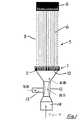
図面を参照しながら、本発明の態様を、我々の先のPCT国際公開第WO98/28066号公報に開示された型の膜モジュールに関連して説明する。この国際公開公報は、相互参照によって、本明細書に組み込まれるが、本発明は他の型の膜モジュールに等しく適用できることが理解されよう。膜モジュール5は、典型的に、繊維状、管状もしくは平らなシート状の形態の膜6を有してなり、膜の両端7及び8は注封(potted)され、膜は支持構造(この場合はスクリーン9)に入れられている。膜の一端又は両端は、透過液捕集用に用いてよい。膜モジュールの底部は、ポット11内に複数の貫通穴10を有し、膜表面を通る気体と液体フィードの混合物を分配させる。
【0027】
図1に示す態様を参照すると、ベンチュリー装置(またはデバイス、device)12等をモジュールの基部に接続している。ベンチュリー装置12は入口13を通して気体を取り入れ、フィード入口14を通る液体の流れと気体を混合し又は液体の流れに気体を同伴させて、気泡を形成し、モジュールの穴10の中に液体/気体混合物を拡散する。分配穴10を通った後、同伴した気泡は液体の流れと共に上方へ流れながら膜表面を洗浄(スクラブまたはこすり洗い)する。液体のフィード又は気体は、システムの要求に応じて、連続的又は断続的注入とすることができる。ベンチュリー装置を用いると、気泡を作ることができ、送風機(またはブロワー:blower)を用いることなくシステムを通気できる。ベンチュリー装置12は、ベンチュリー管、ジェット、ノズル、エゼクター、エダクター、インジェクター等であってよい。
【0028】
図2を参照すると、ジェット又はノズルタイプの装置15の拡大図を示している。この態様において、包囲している空気通路17を有するジェット16を通して液体が押し込まれ、気体を同伴した液体の流れ18を生ずる。そのような装置は各々の供給バルブを調節することによって気体と液体媒体を独立して制御することを可能とする。
【0029】
気体を同伴するために通常使用される液体は、給水、廃水又は濾過されるべき混合液である。ベンチュリー等を通して液体を操作するようなポンピング(pumping)は気体を液体中に吸い込む真空を形成し、また、送風機を使用する場合は気体放出圧力を減少させる。液体の流れの中に気体を供給することによって、分配穴10が閉塞する可能性を実質的に減少する。
【0030】
本発明は少なくともその好ましい態様において、以下のように要約できる多くの利点を提供できる:
1.ベンチュリー装置等を用いることによって、気泡を発生させ、送風機等の加圧した気体供給装置を用いる必要なく、膜の表面をスクラブ洗浄できる。原動力となる流体はベンチュリーを通過する時、真空を生じ、気体を液体の流れに引き込み、その中で気泡を生じさせる。たとえ送風機をまだ必要であるとしても、上述のプロセスを使用することで、送風機の排出圧力を低減し、従って、操作費用が低下する。
【0031】
2.液相と気相はベンチュリー内で十分に混合され、その後膜モジュールの中に拡散し膜をスクラブ洗浄する。ジェットタイプ装置を使用して、液体媒体中に気体を強制的に混入する場合、より速い速度の気泡流れを生ずるという追加の利点が提供される。汚水処理において、使用する気体が空気又は酸素である場合、そのような十分な混合によって、優れた酸素移動が提供される。液体で満たされたパイプ内に気体を直接注入する場合、気体はパイプ壁の上に淀んだ気体の層を形成し、従って、気体と液体はバイパスしてモジュールの別の部分を通過し、その結果低い洗浄効率をもたらすこととなる可能性がある。
【0032】
3.膜に沿う液体の流れによって気泡の流れは強められ、その結果発生する大きなスクラブ洗浄のせん断力を生ずる。気体/液体を供給するこの方法では、気体と液体の流量を独立して調整することができると、積極的な液体移動とアエレーションがもたらされる。
【0033】
4.空気分配装置の穴の中に2相の流体(気体/液体)の混合物を注入することで、脱水された固形物の形成を防ぐことができ、従って、そのような脱水された固形物によって徐々に穴が閉塞することを防止できる。
【0034】
5.更に、注入の配列(アレンジメント)は、モジュールの底部に効率的に洗浄薬剤(cleaning chemical)を注入するための効率的な洗浄機構を提供し、化学的洗浄を促進する洗い流し洗浄力を提供する。上述のモジュール構成で得られる高充填密度と組み合わせると、この配列によって、最少量の洗浄薬剤を用いて繊維を効率的に洗浄できる。
【0035】
6.上述のモジュールの構成は、完全な充填部を著しく増加することなく、モジュール内に繊維のより高い充填密度を可能とする。これは、膜モジュールを曝気槽内に組み込む、あるいは、また、別のタンク内に配置することができるという、追加の融通性を加える。後者の配列において、タンク内に少量の洗浄薬剤を保持するので洗浄薬剤の使用量の点で、また、化学的洗浄工程は自動化できるので、労務費の点で、この利点は著しい節約となる。使用される洗浄薬剤はバイオプロセスにフィードバックされ得、なお有効な酸化剤であり、従って、その洗浄薬剤はバイオプロセスに有害な効果を有し得るから、使用される洗浄薬剤の削減も重要である。従って、バイオプロセス内に存在する化学的な負荷の削減は、どの程度であっても著しい利点を提供する。
【0036】
7.気体と液体フィードの混合物を各々の膜モジュールに積極的に注入することは、膜の周囲でプロセス流体を均一に分配し、従って、濾過の間のフィード濃度の偏り(または分極)を最小にする。大規模のシステムにおいて、また、大量の懸濁物質を含むプロセスフィードについて、濃度の偏りはより大きい。従来技術のシステムでは、そのプロセス流体は通常タンクの一端から入ることが多く、モジュールを横切って移動するにつれて濃縮されるので、均一性に乏しい。その結果、幾つかのモジュールは、他のものよりもはるかに高濃度なものを処理し、そのため、非効率な運転となる。
【0037】
8.濾過効率は、濾過抵抗が減少するので改善される。フィード側の抵抗は、膜の表面への横断パスの減少、並びに気泡及び二相流によって発生する乱れのため減少する。
【0038】
9.そのような洗浄方法を、膜を用いる飲料水、廃水の処理関連プロセスに使用できる。濾過プロセスを吸引又は加圧によって運転できる。
【0039】
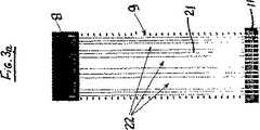
図3〜5には、仕切りを有する種々の配列の態様を示している。再び、これらの態様を円筒形の管状又は繊維膜のバンドル20について示しているが、本発明はそのような用途に制限されるものではないことはいうまでもない。
【0040】
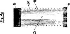
図3は、幾つかの平行な仕切り隙間22によって、幾つかの薄いスライス21に垂直方向に仕切られている管状の膜のバンドル20を示す。バンドルをこのように仕切ることによって、充填密度を著しく損うこと無く、蓄積した固形物をより容易に除去することができる。そのような仕切りを設けることを、ポッティング(注封)プロセスの間に行うことができ、完全な仕切り又は部分的な仕切りを形成できる。仕切られたモジュールを形成するもう一つの方法は、図4に示すようにいくつかの小さな管状の膜のバンドル23を注封(pot)して、各々のモジュールにすることである。
【0041】
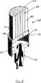
膜モジュールのもう一つの改良された構成を図5に示す。中央の膜のないゾーンは、通路24を形成し、より多くの空気と液体の注入を可能とする。気泡と液体は、管状の膜20に沿って移動し、繊維のアレイを通って上部の注封されたヘッド8にて出て行き、その間、膜の壁をスクラブ洗浄し、物質を除去する。気体のみ又は気体/液体の混合物をモジュールに注入できる。
【0042】
図6は、更に図5と類似するが、繊維膜20に洗浄用液体/気体混合物を入れることができるように、下のポット7の中に一つの中央穴30を有する更に別の態様を示す。この態様において、繊維は、穴30に隣接して延在し、上のポット8に向けて別々のバンドル23に集まる。大きな中央穴30によって、繊維の周囲により大きな液体の流れをもたらし、従って、洗浄効率が向上するすることが見出されている。
【0043】
図7及び8は、図6と同様な膜の構成を有し、図2の態様と同様のジェット混合システムを有する更に別の態様を示す。一つの中央穴30を使用することで、図8に示すように両端にて、繊維20から濾液を取り出すことが可能となる。
【0044】
図9及び10を参照すると、モジュール45は、上の注封ヘッド47及び下の注封ヘッド48に取り付けられ、これらの間で延在する、複数の中空繊維膜のバンドル46を有してなる。注封ヘッド47及び48は、適切なマニホールド(図示せず)に取り付けるため、各々注封スリーブ(potting sleeve)49及び50に配置される。繊維のバンドル46を、スクリーン(仕切り)51によって包囲して、繊維間の過剰な動きを防止する。
【0045】
図9に示すように、下の注封ヘッド48に、幾つかの平行に配置されているスロットタイプのエアレーション穴(通気口、aeration hole)52を設ける。繊維膜53をバンドル46に注封して、繊維のバンドルを横切って延在する隙間54を有する仕切られている配列(アレンジメント)を形成する。エアレーション穴52を、通常仕切りの隙間と一致させるように配置するが、通常、各空間と組み合わせた複数のエアレーション穴が存在する。
【0046】
下の注封スリーブ50は、下のポット48の下に、空洞55を形成する。気体又は液体と気体の混合物を、(上述した)ジェットアッセンブリ57を用いて、この空洞55の中に注入し、その後、膜のアレイの中に穴52を介して通す。
【0047】
使用時には、仕切りを用いることで、特に繊維のバンドルの注封端部の付近では、高エネルギーの流れを洗い流すための気体と液体の混合物とすることができ、それは、膜繊維の周囲で蓄積した固形物を除去することを助長する。
【0048】
微生物の活動に酸素を供給するため、また連続的に膜を洗浄する(scour)ために、膜に連続的に空気を供給するの好ましい。別法では、用途によっては、空気の代りに純酸素又は他の気体の混合物を使用してよい。我々の上述の先の出願で記載したように、上のポットを通る膜の内腔(lumen)に取り付けられる吸引ポンプを用いて、きれいな濾液を膜から引き出す。
【0049】
反応器に高濃度の懸濁物質(MLSS)が存在するので、低い経膜圧力または濾過圧(transmembrane pressure:TMP)条件で、膜モジュールを運転するのが好ましい。
【0050】
膜バイオリアクターは、フィード汚水からの栄養分を更に除去することを助長する無酸素性(または嫌気性)プロセスと組み合わせるのが好ましい。
【0051】
使用されるモジュールシステムは多数の現在のシステムより高いMLSSに対する耐性が高く、効率的な空気洗浄(スクラブ)及び(使用された場合)逆流が、バイオリアクターモジュールの効率的な操作及び性能を助長することが見出されている。
【0052】
本発明及びその態様を、バイオリアクターおよび同様のシステムへの適用に関連して記載したが、本発明は他のタイプの適用についても等しく利用できることが理解されよう。
【0053】
本発明は上述の特定の態様に限定されることはなく、本発明の概念又は範囲から逸脱することなく、本発明の他の態様及び具体例が可能であることが理解されよう。
【図面の簡単な説明】
【図1】 図1は、膜モジュールの1つの態様の模式的側面図を示し、本発明の洗浄方法を説明する。
【図2】 図2は、同伴する気泡を形成するために用いるジェット型配列の1つの形態の、拡大した模式的側面図を示す。
【図3a】 図3aは、本発明の1つの態様に基づく、仕切られた膜モジュールの模式的側面図を示す。
【図3b】 図3bは、図3aの膜のバンドルの断面図を示す。
【図4a】 図4aは、本発明の別の態様に基づく、仕切られた膜モジュールの模式的側面図を示す。
【図4b】 図4bは、図4aの膜のバンドルの断面図を示す。
【図5a】 図5aは、本発明のもう1つの態様に基づく、仕切られた膜モジュールの模式的側面図を示す。
【図5b】 図5bは、図5aの膜のバンドルの断面図を示す。
【図6a】 図6aは、本発明のもう1つの態様に基づく、仕切られた膜モジュールの模式的側面図を示す。
【図6b】 図6bは、図6aの膜のバンドルの断面図を示す。
【図7】 図7は、図2と同様の、本発明の別の態様の図を示す。
【図8】 図8は、図2と同様の、本発明の更に別の態様の図を示す。
【図9】 図9は、本発明の膜モジュールのもう1つの好ましい態様の下端を図解的に示した断面斜視図を示す。
【図10】 図10は、図9の膜モジュールの上端を図解的に示した断面斜視図を示す。[0001]
Technical field
The present invention relates to an apparatus and associated method for efficiently cleaning a membrane module using a gas and liquid mixture formed using a venturi, jet or the like. For example, for membrane modules used in environments where high concentrations of suspended solids (or suspended solids) are present, such as in bioreactors, several types of materials that reduce accumulated substances (or solids) in modules The configuration of the improved module is described.
[0002]
Background of the invention
The importance of membrane modules for sewage treatment is expanding rapidly. It is well known that the membrane process can be used as the third most efficient sewage treatment method and can provide good quality effluent. However, it can be limited by funding and operating costs. With the advent of the submerged membrane process where the membrane module is submerged in a large feed tank and the filtrate is collected by suction used on the filtrate side of the membrane, biological and physical processes are brought together in one stage. The combined membrane bioreactor is expected to be more compact, efficient and economical. Because of its flexibility, membrane bioreactor sizes can range from household (septic tank systems) to community and large-scale sewage treatment.
[0003]
The success of the membrane filtration process is highly dependent on the adoption of effective and efficient membrane cleaning methods. Commonly used physical cleaning methods include backwashing with an osmotic liquid or gas (backpulse, backflush) or scrubbing the membrane surface with a gas that produces bubbles in the liquid. Or there is scoring washout. Examples of the second type of method are US Pat. No. 5,192,456 to Ishida et al. (Ishida et al., United States Patent No. 5,192,456), US Pat. No. 5,248,424 to Coat et al. (Cote et al., United States Patent No. 5,248,424), US Pat. Nos. 5,639,373 and 5,783,083 by Hensha et al. (Henshaw et al., United States Patents No. 5,639,373 and No) 5,783,083) and our international patent application WO 98/28066 (PCT Application No. WO98 / 28066).
[0004]
In the above-described example, in order to form gas bubbles (bubbles) in the liquid system in which the membrane module is immersed, gas is normally injected (injected) using a pressurized air blower. The foam so formed moves upward and rubs and cleans the membrane surface to remove contaminants formed on the membrane surface. The resulting shear stress is highly dependent on the initial bubble velocity, the bubble size and the resultant force applied to the bubble. In this method, fluid movement is limited by the effectiveness of the gas lifting mechanism. In order to improve the scrubbing effect, more gas must be supplied. However, this method has several disadvantages: This method consumes a large amount of energy and can form a mist or froth flow that reduces the effective membrane filtration area, Can be destroyed. Furthermore, in an environment where high concentrations of suspended matter are present, the gas distribution system can become gradually occluded by dehydrated solids, or can simply be occluded if the gas flow stops accidentally.
[0005]
For most tubular membrane modules, the membrane is flexible at the center (longitudinal) of the module, but with a pin and tension toward the potted head at both ends Tend to decrease. When such a module is used in an environment containing a high concentration of suspended solids, the suspended solids can easily be trapped in membrane bundles, especially in the vicinity of the two potting heads (traps). ) Methods for removing accumulated material include improved module structure and improved flow distribution when bubble scrubbing cleaning is used to clean the membrane.
[0006]
When designing a membrane module, the packing density of the tubular membrane within the module is an important factor. The packing density of the fibrous membrane in the membrane module as used in this case is defined as the cross section of the potting area occupied by the fibrous membrane divided by the total potting area and is usually expressed in percent. From an economic point of view, it is preferable that the packing density is as high as possible because the membrane module manufacturing cost can be reduced. In fact, solid packing is reduced in membrane modules packed at a low density. However, if the packing density is too low, the rubbing effect between the membranes can also be reduced, resulting in inefficient cleaning of the membrane surface (scrubbing / scouring). Accordingly, there is a need to provide a membrane structure that maximizes the packing density of the membrane while facilitating removal of accumulated material.
[0007]
Disclosure of the invention
The present invention, at least in aspects of the present invention, seeks to overcome or alleviate some of the disadvantages of the prior art, or at least provide a useful alternative.
[0008]
In accordance with one aspect of the present invention, the present invention provides a method of cleaning (or scrubbing) a membrane surface using a liquid medium entrained with bubbles, the source of the gas. ) Passing the liquid medium past (or past) the liquid medium, entraining the bubbles in the liquid medium, and circulating the bubbles and the liquid medium along the membrane surface for contamination. A method is provided that includes the step of removing material therefrom.
[0009]
Preferably, a venturi device is used to entrain bubbles in the liquid stream. In order to produce a mixture of liquid and bubbles, such as jets, nozzles, ejectors, eductors, injectors, etc., a device that forcibly mixes the gas with the liquid flow is used to cause the bubbles to flow. More preferably it is entrained or injected. Optionally, a supply of additional bubbles may be supplied into the liquid medium using a blower or the like. The gas used can include air, oxygen, gaseous chlorine, ozone. Air is most economical for cleaning (or scrub cleaning) and / or aeration. Gaseous chlorine may be used to improve cleaning (scrub cleaning), disinfection and cleaning efficiency by chemical reaction at the membrane surface. In addition to the effects similar to those described for gaseous chlorine, the use of ozone can oxidize DBP precursors and convert non-biodegradable NOM to biodegradable dissolved organic carbon. There are additional features such as
[0010]
According to a second aspect of the present invention, the present invention is a membrane module comprising a plurality of porous membranes and means for entraining bubbles in a liquid flow, wherein the membranes are arranged close to each other. Also, arranged to prevent excessive movement between them, the means is entrained in the flow of liquid from within the module by means different from the passage of gas through the pores of the membrane. And in use, the liquid and bubbles entrained therein move through the surface of the membrane (or in front of it) to remove contaminants therefrom, A membrane module is provided that draws gas into the liquid flow by entraining the bubbles with the liquid by flowing the liquid past (or in front of) the gas source.
[0011]
Preferably, the liquid and gas are mixed and then flowed past the membrane (or in front of the membrane) to remove contaminants.
[0012]
In one preferred form, the present invention provides a method for removing contaminants from the surface of a plurality of longitudinally extending porous hollow fiber membranes arranged in an array to form a membrane module. The membranes are arranged in close proximity to each other and arranged to prevent excessive movement between them, this method being different from the bubbles passing through the pores of the membrane To produce uniformly distributed bubbles entrained in the flow of liquid from within the array, and to draw and / or mix the liquid into the liquid The bubbles are entrained in the liquid flow by flowing past the source, and the distribution is such that the bubbles pass with the liquid flow substantially uniformly between each membrane of the array. To clean the surface of the membrane (wash Sink, Scour), it is such as to remove solids that have accumulated from the membrane module. Preferably, the bubbles are injected into the liquid stream and mixed.
[0013]
The membrane comprises porous hollow fibers, the fibers being secured at both ends by a header, and the lower header being one or more formed holes (or holes,) that introduce a gas / liquid flow. hole). The holes can be circular, elliptical or slot-shaped. The fibers are usually sealed at the bottom and open at the top so that the filtrate can be removed, but in some arrangements (or arrangements) the fibers may be open at both ends, one or both ends. The filtrate can be removed. The fibers are preferably arranged in the form of a cylindrical array or bundle. It will be appreciated that the cleaning methods described above are equally applicable to other forms of membranes, such as flat or plate-like membranes.
[0014]
According to another aspect, the present invention is a membrane module comprising a plurality of porous hollow fiber membranes, a header and partition means (partition means), the fiber membranes being close to each other. One or more formations that are arranged and arranged to prevent excessive movement between them, each end within the header is fixed, and one header introduces a gas / liquid flow Partition means extending at least partially between the headers to provide membrane modules that divide the membrane fibers into groups. The partition means are preferably formed by gaps (or spaces) between each fiber group. The partitions may be parallel to each other, or if the fiber membrane is a cylindrical array, the partitions may extend radially from the center of the array, or may be cylindrical They may be arranged concentrically in the array. In another embodiment, the fiber bundle may have an intermediate longitudinal passage extending in the longitudinal direction of the bundle between the headers.
[0015]
In accordance with yet another aspect of the present invention, the present invention includes a plurality of porous hollow membrane fibers disposed at each end of each potting head and extending in the longitudinal direction therebetween. A membrane module for use in a membrane bioreactor, wherein the membrane fibers are arranged in close proximity to each other and arranged to prevent excessive movement between them, the fibers being at least each potted Divided into several bundles to form a gap between them at or near the potting head, one potting head is formed to supply air bubbles into the module With an array of aeration openings in use so that, in use, the air bubbles move through (or in front of) the membrane fibers and remove contaminants therefrom.
[0016]
The fiber bundle is protected by a module support screen and the movement of the fiber is restricted. The module support screen has both properly spaced vertical and horizontal elements to provide an unrestricted flow of fluid and gas through the fiber, limiting the width of the fiber movement and the fiber Reduce the energy concentration at the potted edge of the.
[0017]
The aeration opening is preferably arranged so as to coincide with the gap formed between the partitioned bundles. The opening is preferably a slot, a plurality of slots or a row of holes. Preferably, a fiber bundle is placed in the potting head between a plurality of slots or rows of holes.
[0018]
It is preferred to entrain bubbles in the liquid flow, or to mix the liquid flow and bubbles, and then supply the bubbles through the holes or slots, but in some configurations only gas may be used. It will be understood. Use liquid to membrane moduleIn the feedThere may be. The fibers and / or bundles of fibers may cross each other between the potting heads, but preferably are not.
[0019]
The fibers in the module preferably have a packing density of between about 5 and about 70% (as defined above), more preferably between about 8 and about 55%.
[0020]
The diameter of the hole is preferably in the range of about 1-40 mm, and more preferably in the range of about 1.5 to about 25 mm. In the case of a row of slots or holes, the opening area is selected to be equal to the area of the holes described above.
[0021]
The internal diameter of the fiber is typically in the range of about 0.1 mm to about 5 mm, preferably in the range of about 0.25 mm to about 2 mm. The thickness of the fiber wall depends on the material used and the strength required for the filtration efficiency. Typical wall thickness is between 0.05 and 2 mm, more often between 0.1 mm and 1 mm.
[0022]
According to another aspect, the present invention provides a membrane bioreactor comprising a tank and a membrane module according to the first aspect, the tank having means for introducing a feed thereto and activated sludge in the tank. The membrane module is disposed in the tank so as to be submerged in the sludge, and the membrane module is provided with means for drawing filtrate from at least one end of the fiber membrane.
[0023]
According to yet another aspect, the present invention provides a method of operating a membrane bioreactor of the type described in the second aspect, comprising supplying a feed to the tank and applying a vacuum to the fibers. Apply and draw filtrate from them, while in use, supply bubbles through the aeration opening into the module periodically or continuously and the bubbles move through the surface of the membrane fiber And then removing the contaminants. When fed through the holes or slots, the bubbles are preferably entrained in the liquid flow or mixed with the liquid flow.
[0024]
If necessary, an additional source of aeration may be provided in the tank to promote microbial activity. Preferably, the membrane module is suspended vertically in the tank, and the additional source of aeration is provided below the suspended module. The additional source of aeration preferably consists of a group of air permeable tubes. Depending on the flux (flux), the membrane module may be operated with or without backwash. A high concentration of suspended solids liquid (5000-20000 ppm) in the bioreactor was shown to significantly reduce the residence time and improve the quality of the filtrate. The combination of aeration for both organic degradation and membrane cleaning shows that even with high concentrations of MLSS, a constant filtrate flow rate can be achieved without significantly increasing the pressure across the membrane. It was done. With partitioned fiber bundles, higher packing densities can be achieved without significantly adversely affecting the gas scouring process. This results in higher filtration efficiency.
Below, the main aspect of this invention is shown.
1. A method of cleaning a membrane surface using a liquid medium entrained with bubbles, the method comprising entraining the bubbles in the liquid medium by a flow of the liquid medium passing through a gas source, and along the membrane surface Circulating a bubble and a liquid medium and removing contaminants therefrom.
2. The method according to 1 above, wherein bubbles are entrained in the liquid flow using a venturi device.
3. 2. The method of
4). 4. The method according to any one of 1 to 3, wherein the gas comprises air, oxygen, gaseous chlorine, ozone, or any combination thereof.
5). A membrane module comprising a plurality of porous membranes and means for generating bubbles entrained in a liquid flow, wherein the membranes are arranged in close proximity to each other and exhibit excessive movement therebetween. It is arranged to prevent and by means other than passing through the pores of the membrane to generate entrained gas from within the module, and in use, the liquid and the entrained bubbles pass through the surface of the membrane. A membrane module that is adapted to move and remove contaminants from the gas source by flowing the liquid past a gas source and drawing the gas into the liquid stream.
6). 6. The membrane module according to 5 above, wherein the liquid and bubbles are mixed and then flowed past the membrane to remove contaminants.
7). A method for removing contaminants from a surface of a plurality of porous hollow fiber membranes arranged in an array and extending in a longitudinal direction to form a membrane module, wherein the membranes are arranged in close proximity to each other, and Forming uniformly distributed bubbles entrained in the flow of liquid from within the array by means other than passing through the pores of the membrane, arranged to prevent excessive movement between Comprising entraining the bubbles in the liquid flow by flowing the liquid past a gas source to draw and / or mix the gas into the liquid, Substantially uniformly between each membrane of the array, the bubbles pass along with the liquid flow to clean the surface of the membrane and remove accumulated solids from within the membrane module. Method.
8). The method of
9. The membrane comprises porous hollow fibers, the fibers being fixed at each end with a header, at least one header having one or more holes formed to introduce a gas / liquid flow. The method according to 7 or 8.
10. A membrane module comprising a plurality of porous hollow fiber membranes, a header and partition means, the fiber membranes being arranged in close proximity to each other and arranged to prevent excessive movement between them The fiber membrane is secured at each end within the header, one header having one or more holes formed to introduce a gas / liquid flow, and the partition means is at least partly between the headers A membrane module that extends and divides the membrane fibers into groups.
11. 11. The module according to the above 10, wherein the partition means is formed by a gap between each fiber group.
12 12. The module of claim 11, wherein the fiber membranes are arranged in a cylindrical array, and the partition means extend radially from the center of the array or are arranged concentrically within the cylindrical array.
13. A membrane module comprising a plurality of porous hollow fiber membranes, headers and fiber bundles, wherein the fiber membranes are arranged in close proximity to each other to form a bundle and prevent excessive movement between them The fiber membrane is fixed at each end within the header, and one header has one or more holes formed to introduce gas / liquid, the length of the bundle between the headers Membrane module in which the fiber bundle has a long passage in the middle part extending over
14 A membrane module used in a membrane bioreactor including a plurality of porous hollow membrane fibers each having an end attached to each potting head and extending in the longitudinal direction between the potting heads, Arranged close to each other and arranged to prevent excessive movement between them, the fibers are partitioned into several bundles at least at each potting head or adjacent to each potting head. One of the potting heads has an array of aeration openings formed to supply air bubbles into the module, and in use, the air bubbles A membrane module that moves past the surface of the fiber and removes contaminants from them.
15. 15. The membrane module according to 14 above, wherein an aeration opening is arranged so as to coincide with a gap formed between the partitioned bundles.
16. 16. The membrane module as described in 15 above, wherein the opening is a slot, a plurality of slots or a row of holes, and the bundle of fibers is arranged in the potting head between the rows of slots or holes.
17. The membrane module of
18. The membrane module of
19. 17. The membrane module as described in 16 above, wherein the hole has a diameter in the range of about 1 to 40 mm or an equivalent diameter.
20. 17. The membrane module as described in 16 above, wherein the hole has a diameter in the range of about 1.5 to 25 mm or an equivalent diameter.
21. 15. The membrane module according to 10, 13, or 14, wherein the inner diameter of each of the fibers is about 0.1 mm to about 5 mm.
22. 15. The membrane module according to 10, 13, or 14, wherein the inner diameter of each of the fibers is about 0.25 mm to about 2 mm.
23. 15. The membrane module according to 10, 13, or 14, wherein the wall thickness of each of the fibers is about 0.05 to about 2 mm.
24. 15. The membrane module according to 10, 13, or 14, wherein the wall thickness of each of the fibers is about 0.1 mm to about 1 mm.
25. A membrane bioreactor comprising a tank having feed introduction means, means for forming activated sludge in the tank, and the membrane module according to 10, 13, or 14, wherein the membrane module is submerged in the sludge. A membrane bioreactor in which a membrane module is provided with means arranged in the tank to draw filtrate from at least one end of the fiber membrane.
26. Supplying feed to the tank, applying a vacuum to the fibers and then drawing the filtrate, while supplying bubbles periodically or continuously through the aeration opening into the module, A method of operating a membrane bioreactor of
27. 27. The method of claim 26, wherein bubbles are entrained or mixed with the liquid flow when fed through the holes or slots.
28. 26. The membrane module as described in 25 above, wherein the membrane module is suspended vertically in the tank, and an aeration source is provided under the suspended module.
29. 29. The membrane module of claim 28, wherein the aeration source comprises a group of gas distributors or air permeable tubes.
30. A membrane module substantially as described with reference to any of the aspects described above and the related drawings.
31. A method of scrubbing a film surface substantially as described with reference to any of the above aspects and the related drawings.
[0025]
Preferred embodiments of the present invention will now be described, by way of example only, with reference to the accompanying drawings.
[0026]
Preferred embodiments of the present invention
With reference to the drawings, embodiments of the present invention will be described in the context of a membrane module of the type disclosed in our previous PCT International Publication No. WO 98/28066. This International Publication is incorporated herein by cross-reference, but it will be understood that the present invention is equally applicable to other types of membrane modules. The
[0027]
Referring to the embodiment shown in FIG. 1, a venturi device (or device) 12 or the like is connected to the base of the module.
[0028]
Referring to FIG. 2, an enlarged view of a jet or nozzle type device 15 is shown. In this embodiment, liquid is forced through a
[0029]
Liquids commonly used for entraining gases are feed water, waste water or a mixture to be filtered. Pumping, such as manipulating liquid through a venturi or the like, creates a vacuum that draws gas into the liquid, and reduces the gas discharge pressure when using a blower. By supplying a gas into the liquid flow, the possibility of blockage of the dispensing holes 10 is substantially reduced.
[0030]
The present invention, at least in its preferred embodiments, can provide a number of advantages that can be summarized as follows:
1. By using a venturi device or the like, bubbles can be generated and the surface of the membrane can be scrubbed without the need to use a pressurized gas supply device such as a blower. When the motive fluid passes through the venturi, it creates a vacuum, drawing the gas into the liquid flow and creating bubbles therein. Even if a blower is still required, using the process described above reduces the blower discharge pressure, thus reducing operating costs.
[0031]
2. The liquid and gas phases are thoroughly mixed in the venturi and then diffused into the membrane module to scrub the membrane. The additional advantage of using a jet-type device to force gas into the liquid medium provides a faster velocity of bubble flow. In sewage treatment, if the gas used is air or oxygen, such thorough mixing provides excellent oxygen transfer. When injecting gas directly into a pipe filled with liquid, the gas forms a stagnant gas layer on the pipe wall, so that the gas and liquid bypass and pass through another part of the module. The result can be low cleaning efficiency.
[0032]
3. The flow of bubbles along the membrane intensifies the bubble flow, resulting in the resulting large scrub cleaning shear force. This method of supplying gas / liquid provides positive liquid movement and aeration if the gas and liquid flow rates can be adjusted independently.
[0033]
4). By injecting a two-phase fluid (gas / liquid) mixture into the holes of the air distributor, the formation of dehydrated solids can be prevented, and therefore gradually with such dehydrated solids. It is possible to prevent the hole from being blocked.
[0034]
5). Furthermore, the injection arrangement provides an efficient cleaning mechanism for efficiently injecting a cleaning chemical into the bottom of the module and provides a flushing power that promotes chemical cleaning. In combination with the high packing density obtained with the module configuration described above, this arrangement allows the fibers to be efficiently cleaned using a minimum amount of cleaning agent.
[0035]
6). The configuration of the module described above allows for a higher packing density of fibers in the module without significantly increasing the complete packing. This adds the additional flexibility that the membrane module can be incorporated into the aeration tank or alternatively placed in a separate tank. In the latter arrangement, a small amount of cleaning chemical is retained in the tank, so that this advantage is a significant saving in terms of the amount of cleaning chemical used and the chemical cleaning process can be automated. Since the cleaning agent used can be fed back into the bioprocess and is still an effective oxidant, therefore, the cleaning agent used can also have detrimental effects on the bioprocess, so reducing the cleaning agent used is also important . Thus, any reduction in the chemical load present within a bioprocess provides significant advantages to any degree.
[0036]
7). Aggressively injecting a mixture of gas and liquid feed into each membrane module distributes the process fluid evenly around the membrane, thus minimizing feed concentration bias (or polarization) during filtration . In large scale systems and for process feeds that contain large amounts of suspended matter, the concentration bias is greater. In prior art systems, the process fluid usually enters from one end of the tank and is concentrated as it moves across the module, resulting in poor uniformity. As a result, some modules handle much higher concentrations than others, thus resulting in inefficient operation.
[0037]
8). Filtration efficiency is improved because the filtration resistance is reduced. The resistance on the feed side is reduced due to the reduced crossing path to the surface of the membrane and the turbulence generated by bubbles and two-phase flow.
[0038]
9. Such a cleaning method can be used for treatment-related processes of drinking water and wastewater using a membrane. The filtration process can be operated by suction or pressurization.
[0039]
3 to 5 show various arrangement modes having partitions. Again, although these embodiments are shown for a cylindrical tubular or
[0040]
FIG. 3 shows a
[0041]
Another improved configuration of the membrane module is shown in FIG. A zone without a central membrane forms a
[0042]
FIG. 6 is further similar to FIG. 5 but shows a further embodiment having one
[0043]
7 and 8 show yet another embodiment having a membrane configuration similar to that of FIG. 6 and having a jet mixing system similar to that of FIG. By using one
[0044]
Referring to FIGS. 9 and 10, the
[0045]
As shown in FIG. 9, the
[0046]
The
[0047]
In use, a divider can be used to create a gas and liquid mixture to wash away the high energy flow, especially near the potted end of the fiber bundle, which has accumulated around the membrane fibers. Helps remove solids.
[0048]
In order to supply oxygen for microbial activity and to continuously scour the membrane, it is preferable to supply air continuously to the membrane. Alternatively, depending on the application, pure oxygen or a mixture of other gases may be used instead of air. The clean filtrate is drawn from the membrane using a suction pump attached to the membrane lumen through the upper pot as described in our earlier application.
[0049]
Because of the high concentration of suspended matter (MLSS) present in the reactor, it is preferred to operate the membrane module at low transmembrane pressure or transmembrane pressure (TMP) conditions.
[0050]
The membrane bioreactor is preferably combined with an anaerobic (or anaerobic) process that facilitates further removal of nutrients from the feed sewage.
[0051]
The modular system used is more resistant to MLSS than many current systems, and efficient air scrubbing (if used) and backflow (if used) facilitate efficient operation and performance of the bioreactor module. It has been found.
[0052]
Although the present invention and its embodiments have been described in connection with application to bioreactors and similar systems, it will be understood that the present invention is equally applicable to other types of applications.
[0053]
It will be understood that the invention is not limited to the specific embodiments described above, and that other embodiments and embodiments of the invention are possible without departing from the concept or scope of the invention.
[Brief description of the drawings]
FIG. 1 shows a schematic side view of one embodiment of a membrane module, illustrating the cleaning method of the present invention.
FIG. 2 shows an enlarged schematic side view of one form of jet-type array used to form entrained bubbles.
FIG. 3a shows a schematic side view of a partitioned membrane module according to one embodiment of the present invention.
FIG. 3b shows a cross-sectional view of the membrane bundle of FIG. 3a.
FIG. 4a shows a schematic side view of a partitioned membrane module according to another aspect of the present invention.
4b shows a cross-sectional view of the membrane bundle of FIG. 4a.
FIG. 5a shows a schematic side view of a partitioned membrane module according to another aspect of the present invention.
FIG. 5b shows a cross-sectional view of the membrane bundle of FIG. 5a.
FIG. 6a shows a schematic side view of a partitioned membrane module according to another aspect of the present invention.
6b shows a cross-sectional view of the membrane bundle of FIG. 6a.
FIG. 7 shows a diagram of another aspect of the invention, similar to FIG.
FIG. 8 shows a diagram of yet another aspect of the invention similar to FIG.
FIG. 9 is a cross-sectional perspective view schematically showing the lower end of another preferred embodiment of the membrane module of the present invention.
FIG. 10 is a cross-sectional perspective view schematically showing the upper end of the membrane module of FIG. 9;
Claims (23)
Translated fromJapanese膜モジュールは、複数の多孔質中空繊維膜、上方の注封ヘッド、下方の注封ヘッド及びベンチュリー装置を有し、
各中空繊維膜の第一端部は、上方の注封ヘッドに取り付けられ、
各中空繊維膜の第二端部は、下方の注封ヘッドに取り付けられ、
下方の注封ヘッドは、複数のエアレーション開口部を有し、及び気体の供給源と供給液体の供給源に接続されたベンチュリー装置と接続され、
ベンチュリー装置は、液体に気泡を強制的に混合し、液体に気泡を同伴させ又は注入して、液体と気泡の混合物を生成し下方注封ヘッドに入れるように構成される、濾過装置。A filtration device comprising a membrane module, a gas source and a supply liquid source,
The membrane module has a plurality of porous hollow fiber membranes, an upper pottinghead, a lower pottinghead and a venturi device ,
The first end of each hollow fiber membrane is attached to the upper potting head,
The second end of each hollow fiber membrane is attached to the lower potting head,
Lower potting headhas a plurality of aeration openings, andare connected to the connected venturi device to supply a source of feed liquid gas,
The venturi device is a filtration device configuredto forcibly mix bubbles into a liquid and entrain or inject bubbles into the liquid to produce a mixture of liquid and bubbles into a lower potting head.
パーティションは、多孔質中空繊維膜の間に延びて、多孔質中空繊維膜を複数のグループに分ける請求項1〜6のいずれかに記載の濾過装置。The membrane module further has a partition,
The partition according to any one of claims 1 to6 , wherein the partition extends between the porous hollow fiber membranes and divides the porous hollow fiber membranes into a plurality of groups.
膜は、複数の孔を有し、
膜は、相互に近接して配列され、膜相互間の過度の動きを防止するように配置され、
該方法は、実質的に均一な分布で同伴する複数の気泡と液体の混合物をそのアレイ内から供給する工程を有し、
中空繊維は、第一端部は第1注封ヘッドで固定され、第二端部は第2注封ヘッドで固定され、少なくとも一方の注封ヘッドは、気泡と液体の混合物を導入するために形成された一又はそれ以上の穴を有し、
液体は、供給液体を含み、
注封ヘッドに接続されるベンチュリー装置に液体と気体を流し、液体に気体を強制的に混合することで、気泡は、液体中に同伴して、気泡と液体の混合物を生成し、
該気泡の分布は、該配列内の各膜の間に気泡が実質的に均一に通過し、液体との組み合わせで、膜の外面の汚れを落とし膜モジュール内から蓄積した固体を除去する分布である方法。A method for removing contaminants from the surfaces of a plurality of porous hollow fiber membranes arranged in an array to form a membrane module and extending in the longitudinal direction,
The membrane has a plurality of pores;
The membranes are arranged close to each other and arranged to prevent excessive movement between the membranes,
The methodincludes a stepof supplyinga plurality ofmixtures of gas bubbles andliquid entrained in thesubstantive uniform distribution from within the array,
The hollow fiber has a first end fixed with a first potting head, a second end fixed with a second potting head, at least one potting head for introducing a mixture of bubbles and liquid Having one or more holes formed;
The liquid includes a supply liquid,
By flowing liquid and gas into the venturi device connected to the potting head and forcing the gas into the liquid, the bubbles are entrained in the liquid to produce a mixture of bubbles and liquid,
The distribution of the bubbles is a distribution in which the bubbles pass substantially uniformly between the membranes in the array, and in combination with theliquid , the outer surface of the membrane is removed to remove the accumulated solid from the membrane module. There is a way.
中空繊維膜は、相互に近接して配置され、それらの間の過度の動きを防止するように取り付けられ、
中空繊維膜は、第一端部で第1注封ヘッドに取り付けられ、第二端部で第2注封ヘッドに取り付けられ、
第1注封ヘッドは、気体と供給液体の流れを導入可能に形成された一又はそれ以上の開口部を有し、
パーティションは、第1及び第2注封ヘッドの間に少なくとも部分的に延びて、中空繊維膜を複数のグループに分け、
第1注封ヘッドは、気体の供給源と供給液体の供給源に接続されるベンチュリー装置と接続され、
ベンチュリー装置は、液体に気泡を強制的に混合し、液体に気泡を同伴させ又は注入して、液体と気泡の混合物を生成し第1注封ヘッドに入れるように構成される、膜モジュール。A membrane module comprising a first potting head, asecond potting head, a partition, a venturi device, and a plurality of porous hollow fiber membranes;
The hollow fiber membranes are placed close to each other and attached to prevent excessive movement between them,
The hollow fiber membrane is attached to the first potting head at the first end, and attached to the second potting head at the second end,
The first potting head has one or more openings formed to be able to introduce a flow of gas and supply liquid;
The partition extends at least partially betweenthe first and second potting heads todivide the hollow fiber membranes into a plurality of groups;
The first potting head is connected to a venturi device connected to a gas supply source and a supply liquid supply source,
The venturi device is configured to forcibly mix bubbles into a liquid and entrain or inject bubbles into the liquid to produce a mixture of liquid and bubbles into the first potting head .
Applications Claiming Priority (10)
| Application Number | Priority Date | Filing Date | Title |
|---|---|---|---|
| AU1112 | 1997-03-05 | ||
| AUPP6218AAUPP621898A0 (en) | 1998-09-25 | 1998-09-25 | Apparatus and method for cleaning membrane filtration modules |
| AUPP6218 | 1998-09-25 | ||
| AUPP6217AAUPP621798A0 (en) | 1998-09-25 | 1998-09-25 | Membrane bioreactor |
| AUPP6217 | 1998-09-25 | ||
| AU6217 | 1999-06-21 | ||
| AUPQ1112AAUPQ111299A0 (en) | 1999-06-21 | 1999-06-21 | Improved membrane bioreactor |
| AU6218 | 1999-06-21 | ||
| AUPQ1112 | 1999-06-21 | ||
| PCT/AU1999/000817WO2000018498A1 (en) | 1998-09-25 | 1999-09-24 | Apparatus and method for cleaning membrane filtration modules |
Publications (3)
| Publication Number | Publication Date |
|---|---|
| JP2002525197A JP2002525197A (en) | 2002-08-13 |
| JP2002525197A5 JP2002525197A5 (en) | 2006-11-02 |
| JP5038555B2true JP5038555B2 (en) | 2012-10-03 |
Family
ID=27158102
Family Applications (1)
| Application Number | Title | Priority Date | Filing Date |
|---|---|---|---|
| JP2000572010AExpired - Fee RelatedJP5038555B2 (en) | 1998-09-25 | 1999-09-24 | Filtration membrane module cleaning apparatus and cleaning method |
Country Status (11)
| Country | Link |
|---|---|
| US (1) | US6524481B2 (en) |
| JP (1) | JP5038555B2 (en) |
| KR (2) | KR100704328B1 (en) |
| CN (1) | CN1147349C (en) |
| AU (1) | AU752765B2 (en) |
| CA (1) | CA2342346C (en) |
| MX (2) | MX257860B (en) |
| MY (1) | MY121098A (en) |
| NZ (1) | NZ510394A (en) |
| TW (1) | TWI222895B (en) |
| WO (1) | WO2000018498A1 (en) |
Families Citing this family (144)
| Publication number | Priority date | Publication date | Assignee | Title |
|---|---|---|---|---|
| US8852438B2 (en) | 1995-08-11 | 2014-10-07 | Zenon Technology Partnership | Membrane filtration module with adjustable header spacing |
| US6863823B2 (en)* | 2001-03-23 | 2005-03-08 | Zenon Environmental Inc. | Inverted air box aerator and aeration method for immersed membrane |
| US7087173B2 (en)* | 1995-08-11 | 2006-08-08 | Zenon Environmental Inc. | Inverted cavity aerator for membrane module |
| DE69632422T2 (en)* | 1995-08-11 | 2005-05-19 | Zenon Environmental Inc., Oakville | Process for embedding hollow fiber membranes |
| US20040232076A1 (en)* | 1996-12-20 | 2004-11-25 | Fufang Zha | Scouring method |
| ES2353254T3 (en) | 1996-12-20 | 2011-02-28 | Siemens Water Technologies Corp. | WASHING PROCEDURE |
| US6641733B2 (en)* | 1998-09-25 | 2003-11-04 | U. S. Filter Wastewater Group, Inc. | Apparatus and method for cleaning membrane filtration modules |
| AUPP985099A0 (en)* | 1999-04-20 | 1999-05-13 | Usf Filtration And Separations Group Inc. | Membrane filtration manifold system |
| AUPQ680100A0 (en)* | 2000-04-10 | 2000-05-11 | Usf Filtration And Separations Group Inc. | Hollow fibre restraining system |
| SG93246A1 (en)* | 2000-07-12 | 2002-12-17 | C H Krishnamurthi Rao Dr | A membrane filter element |
| JP2002058968A (en)* | 2000-08-18 | 2002-02-26 | Suehiro Tadashi | Filter |
| DE10045227C1 (en)* | 2000-09-13 | 2002-02-07 | Vosenkaul Klaus | Membrane filter for water treatment uses capillary membrane fibre bundle projecting into untreated water and fitting into permeate collection space at opposite end |
| AT408955B (en)* | 2000-09-28 | 2002-04-25 | Va Tech Wabag Gmbh | MEMBRANE FILTER SYSTEM AND METHOD FOR FILTERING |
| AUPR064800A0 (en)* | 2000-10-09 | 2000-11-02 | Usf Filtration And Separations Group Inc. | Improved membrane filtration system |
| AUPR094600A0 (en)* | 2000-10-23 | 2000-11-16 | Usf Filtration And Separations Group Inc. | Fibre membrane arrangement |
| AUPR143400A0 (en)* | 2000-11-13 | 2000-12-07 | Usf Filtration And Separations Group Inc. | Modified membranes |
| DE10106722B4 (en)* | 2001-02-14 | 2008-11-06 | Fraunhofer-Gesellschaft zur Förderung der angewandten Forschung e.V. | Special hollow fiber membrane module for use in heavily fouled processes and its production |
| AUPR421501A0 (en) | 2001-04-04 | 2001-05-03 | U.S. Filter Wastewater Group, Inc. | Potting method |
| AUPR584301A0 (en)* | 2001-06-20 | 2001-07-12 | U.S. Filter Wastewater Group, Inc. | Membrane polymer compositions |
| AUPR692401A0 (en)* | 2001-08-09 | 2001-08-30 | U.S. Filter Wastewater Group, Inc. | Method of cleaning membrane modules |
| AUPR774201A0 (en)* | 2001-09-18 | 2001-10-11 | U.S. Filter Wastewater Group, Inc. | High solids module |
| EP1312408B1 (en)* | 2001-11-16 | 2006-07-19 | US Filter Wastewater Group, Inc. | Method of cleaning membranes |
| US7247238B2 (en) | 2002-02-12 | 2007-07-24 | Siemens Water Technologies Corp. | Poly(ethylene chlorotrifluoroethylene) membranes |
| AUPS300602A0 (en)* | 2002-06-18 | 2002-07-11 | U.S. Filter Wastewater Group, Inc. | Methods of minimising the effect of integrity loss in hollow fibre membrane modules |
| KR100445982B1 (en)* | 2002-06-20 | 2004-08-25 | 김정학 | System and apparatus for filtering water using hollow fiber membrane |
| US6841083B2 (en) | 2002-06-27 | 2005-01-11 | Ethicon, Inc. | Device and process for improved scouring efficiency |
| US8147699B2 (en)* | 2002-08-21 | 2012-04-03 | Hpd, Llc | Monolith filter apparatus and membrane apparatus, and method using same |
| AU2002950934A0 (en)* | 2002-08-21 | 2002-09-12 | U. S. Filter Wastewater Group, Inc. | Aeration method |
| KR101002466B1 (en) | 2002-10-10 | 2010-12-17 | 지멘스 워터 테크놀로지스 코포레이션 | Back wash method |
| AU2002953111A0 (en)* | 2002-12-05 | 2002-12-19 | U. S. Filter Wastewater Group, Inc. | Mixing chamber |
| DE602004013731D1 (en)* | 2003-03-05 | 2008-06-26 | Hydranautics | DIPLOCKABLE MEMBRANE MODULE WITH REPLACEABLE MEMBRANE ELEMENTS |
| CN100363093C (en)* | 2003-06-17 | 2008-01-23 | 旭化成化学株式会社 | Membrane cartridge, membrane separation device, and membrane separation method |
| AU2003903507A0 (en) | 2003-07-08 | 2003-07-24 | U. S. Filter Wastewater Group, Inc. | Membrane post-treatment |
| NZ545206A (en) | 2003-08-29 | 2009-03-31 | Siemens Water Tech Corp | Backwash |
| CN100396390C (en)* | 2003-10-10 | 2008-06-25 | 财团法人工业技术研究院 | Method and apparatus for treating surface of substrate using bubbles |
| CA2544626C (en) | 2003-11-14 | 2016-01-26 | U.S. Filter Wastewater Group, Inc. | Closed aeration and backwash device for use with membrane filtration module |
| US7392811B2 (en) | 2004-02-23 | 2008-07-01 | Ecolab Inc. | Delivery head for multiple phase treatment composition, vessel including a delivery head, and method for treating a vessel interior surface |
| US7247210B2 (en) | 2004-02-23 | 2007-07-24 | Ecolab Inc. | Methods for treating CIP equipment and equipment for treating CIP equipment |
| US7220358B2 (en) | 2004-02-23 | 2007-05-22 | Ecolab Inc. | Methods for treating membranes and separation facilities and membrane treatment composition |
| KR100453329B1 (en)* | 2004-03-08 | 2004-10-21 | 주식회사 나노엔텍 | Fine filtering apparatus controllable packing density using flexible fiber |
| US8758621B2 (en) | 2004-03-26 | 2014-06-24 | Evoqua Water Technologies Llc | Process and apparatus for purifying impure water using microfiltration or ultrafiltration in combination with reverse osmosis |
| JP2007535398A (en) | 2004-04-22 | 2007-12-06 | シーメンス ウォーター テクノロジース コーポレイション | Filtration device including membrane bioreactor and treatment tank for digesting organic substances, and waste liquid treatment method |
| FR2869552B1 (en)* | 2004-04-29 | 2007-04-06 | Otv Sa | FILTERING DEVICE FOR THE TREATMENT OF WATER, OF THE TYPE OF IMMERSIONED MEMBRANES, INCLUDING ANTI-FLOW MEANS OF THE MEDIUM TO BE FILTERED TO MEANS FOR INJECTING A DECOLMING GAS. |
| WO2005118115A1 (en)* | 2004-05-26 | 2005-12-15 | Trisep Corporation | Network for supporting spiral wound membrane cartridges for submerged operation |
| DE102004029141A1 (en)* | 2004-06-17 | 2005-12-29 | Koch Membrane Systems Gmbh | Membrane module for a dive operation |
| KR100893308B1 (en)* | 2004-06-17 | 2009-04-15 | 코흐 멤브라네 시스템즈 게엠베하 | Submerged membrane module |
| CN102512986A (en)* | 2004-07-02 | 2012-06-27 | 西门子工业公司 | Gas transfer membrane |
| EP1773477B1 (en) | 2004-07-05 | 2011-09-07 | Siemens Water Technologies Corp. | Hydrophilic membranes |
| CN101052457B (en)* | 2004-08-20 | 2012-07-04 | 西门子工业公司 | Square mbr manifold system |
| CN101043933B (en) | 2004-09-07 | 2012-09-05 | 西门子工业公司 | Reduction of backwash liquid waste |
| AU2005284677B2 (en)* | 2004-09-14 | 2010-12-23 | Evoqua Water Technologies Llc | Methods and apparatus for removing solids from a membrane module |
| NZ553771A (en) | 2004-09-15 | 2010-11-26 | Siemens Water Tech Corp | Continuously variable aeration of membrane filtration system and flow control device when used in such application |
| US7118674B2 (en)* | 2004-10-14 | 2006-10-10 | Itt Manufacturing Enterprises, Inc. | Energy-efficient biological treatment with membrane filtration |
| AU2006216078B2 (en)* | 2004-11-02 | 2011-10-06 | Evoqua Water Technologies Llc | Submerged cross flow filtration |
| US7591950B2 (en) | 2004-11-02 | 2009-09-22 | Siemens Water Technologies Corp. | Submerged cross-flow filtration |
| EP1819426A4 (en)* | 2004-11-02 | 2009-08-12 | Siemens Water Tech Corp | Submerged cross-flow filtration |
| US20060108275A1 (en)* | 2004-11-08 | 2006-05-25 | Cote Pierre L | Membrane filtration assemblies for sand filter retrofit |
| KR20070089981A (en)* | 2004-12-03 | 2007-09-04 | 지멘스 워터 테크놀로지스 코포레이션 | Post-treatment of membrane |
| TWI277440B (en) | 2004-12-14 | 2007-04-01 | Asahi Kasei Chemicals Corp | Hollow fiber membrane cartridge |
| NZ555882A (en)* | 2004-12-16 | 2010-08-27 | Idexx Lab Inc | Apparatus and method to elute microorganisms from a filter |
| AU2005318871B2 (en)* | 2004-12-24 | 2011-04-07 | Evoqua Water Technologies Llc | Simple gas scouring method and apparatus |
| WO2006066350A1 (en)* | 2004-12-24 | 2006-06-29 | Siemens Water Technologies Corp. | Simple gas scouring method and apparatus |
| WO2006066319A1 (en) | 2004-12-24 | 2006-06-29 | Siemens Water Technologies Corp. | Cleaning in membrane filtration systems |
| WO2006074519A1 (en)* | 2005-01-14 | 2006-07-20 | Siemens Water Technologies Corp. | Filtration system |
| US7279100B2 (en)* | 2005-01-31 | 2007-10-09 | Ashbrook Simon-Hartley Operations, Lp | Methods and apparatus for treating wastewater employing a high rate clarifier and a membrane |
| JP4951860B2 (en)* | 2005-01-31 | 2012-06-13 | 東洋紡績株式会社 | Method for producing permselective membrane module and permselective membrane module |
| JP2008539054A (en) | 2005-04-29 | 2008-11-13 | シーメンス・ウォーター・テクノロジーズ・コーポレイション | Chemical cleaning for membrane filters |
| NZ563980A (en)* | 2005-06-20 | 2011-07-29 | Siemens Water Tech Corp | Cross linking treatment of polymer membranes |
| CN101222972B (en) | 2005-07-14 | 2014-12-03 | 伊沃夸水处理技术有限责任公司 | Monopersulfate treatment of membranes |
| US8858796B2 (en) | 2005-08-22 | 2014-10-14 | Evoqua Water Technologies Llc | Assembly for water filtration using a tube manifold to minimise backwash |
| CN100420509C (en)* | 2005-09-16 | 2008-09-24 | 中国石油化工股份有限公司 | Membrane cleaning device, cleaning method and application thereof in membrane separation technology |
| WO2007044345A2 (en)* | 2005-10-05 | 2007-04-19 | Siemens Water Technologies Corp. | Method and apparatus for treating wastewater |
| US20070138090A1 (en)* | 2005-10-05 | 2007-06-21 | Jordan Edward J | Method and apparatus for treating wastewater |
| US20070084795A1 (en)* | 2005-10-05 | 2007-04-19 | Jordan Edward J | Method and system for treating wastewater |
| JP4993901B2 (en)* | 2005-11-29 | 2012-08-08 | 水ing株式会社 | Hollow fiber membrane module |
| US20070163942A1 (en)* | 2006-01-19 | 2007-07-19 | Toray Industries, Inc. | Hollow fiber membrane module |
| US7455765B2 (en) | 2006-01-25 | 2008-11-25 | Siemens Water Technologies Corp. | Wastewater treatment system and method |
| JP4954276B2 (en)* | 2006-05-02 | 2012-06-13 | ニルセン ビルジル | Apparatus and method for separating and filtering particles and organisms from bulk fluid flow |
| US20070280282A1 (en)* | 2006-06-05 | 2007-12-06 | Tzeng Shing-Wu P | Indoor digital multimedia networking |
| SG141244A1 (en)* | 2006-09-08 | 2008-04-28 | Ultra Flo Pte Ltd | Filter renewal system and a method thereof |
| DE102006044624B4 (en)* | 2006-09-19 | 2008-07-10 | Koch Membrane Systems Gmbh | Apparatus for fumigating a liquid |
| EP2076467A4 (en)* | 2006-10-17 | 2012-08-29 | Siemens Industry Inc | Membrane bioreactor for phosphorus removal |
| US8293098B2 (en) | 2006-10-24 | 2012-10-23 | Siemens Industry, Inc. | Infiltration/inflow control for membrane bioreactor |
| US20080099399A1 (en)* | 2006-10-27 | 2008-05-01 | Its Engineered Systems, Inc. | Filtration system |
| AU2008215180A1 (en)* | 2007-02-16 | 2008-08-21 | Siemens Industry, Inc. | Membrane filtration process and design |
| US8318028B2 (en) | 2007-04-02 | 2012-11-27 | Siemens Industry, Inc. | Infiltration/inflow control for membrane bioreactor |
| US9764288B2 (en) | 2007-04-04 | 2017-09-19 | Evoqua Water Technologies Llc | Membrane module protection |
| CN101820980B (en)* | 2007-05-14 | 2013-08-28 | 三菱丽阳株式会社 | Membrane filter unit |
| KR101122323B1 (en)* | 2007-05-22 | 2012-03-23 | 아사히 가세이 케미칼즈 가부시키가이샤 | Hollow fiber membrane module, process for manufacturing the same, hollow fiber membrane module assembly and method of purifying suspended water with use thereof |
| US8150261B2 (en)* | 2007-05-22 | 2012-04-03 | Owlink Technology, Inc. | Universal remote control device |
| CA2688455C (en) | 2007-05-29 | 2019-12-03 | Siemens Water Technologies Corp. | Pulsed random two phase gas/liquid flow for cleaning membrane surfaces |
| CA2686937A1 (en)* | 2007-05-29 | 2008-12-04 | Siemens Water Technologies Corp. | Membrane cleaning using an airlift pump |
| CN201098607Y (en)* | 2007-07-27 | 2008-08-13 | 苏州立升净水科技有限公司 | Hollow fibre film component with function of preventing hollow fibre film thread breaking |
| US8574431B2 (en)* | 2008-03-18 | 2013-11-05 | Municipal Filtration Company, Llc | Filter system with gas agitation |
| TWI480104B (en)* | 2008-04-24 | 2015-04-11 | Graco Minnesota Inc | Method of cleaning fast setting material spray equipment |
| WO2010009518A1 (en) | 2008-07-24 | 2010-01-28 | Siemens Water Technologies Corp. | Frame system for membrane filtration modules |
| JP2012500117A (en) | 2008-08-20 | 2012-01-05 | シーメンス ウォーター テクノロジース コーポレイション | Improving backwash energy efficiency of membrane filtration systems. |
| US20110272335A1 (en)* | 2009-01-14 | 2011-11-10 | Pierre Lucien Cote | Immersed membrane cassette and method of operation |
| JP2009113042A (en)* | 2009-02-05 | 2009-05-28 | Asahi Kasei Chemicals Corp | Header parts and their connection structures |
| JP2010188278A (en)* | 2009-02-18 | 2010-09-02 | Kobelco Eco-Solutions Co Ltd | Gas diffuser, membrane module, membrane separator, gas diffusion method and membrane separation method |
| US7875176B2 (en)* | 2009-03-06 | 2011-01-25 | Porous Media Corporation | Membrane module for fluid filtration |
| CN101830555B (en)* | 2009-03-09 | 2011-12-28 | 江西金达莱环保研发中心有限公司 | Jet aeration device and jet aeration method thereof |
| JP4968281B2 (en)* | 2009-03-27 | 2012-07-04 | ブラザー工業株式会社 | Cleaning unit and printing apparatus equipped with the same |
| AU2010101488B4 (en) | 2009-06-11 | 2013-05-02 | Evoqua Water Technologies Llc | Methods for cleaning a porous polymeric membrane and a kit for cleaning a porous polymeric membrane |
| WO2011136888A1 (en) | 2010-04-30 | 2011-11-03 | Siemens Industry, Inc | Fluid flow distribution device |
| FR2961413B1 (en)* | 2010-06-18 | 2015-01-16 | Polymem | WATER FILTRATION MODULE AND METHOD OF MANUFACTURE AND USE |
| KR101231295B1 (en) | 2010-08-23 | 2013-02-07 | 주식회사 효성 | Submerged hollow fiber membrane module |
| CN101954244B (en)* | 2010-08-30 | 2012-10-10 | 蓝星环境工程有限公司 | Gas-water jet device and gas-shield water jet membrane physical cleaning device |
| WO2012040412A1 (en) | 2010-09-24 | 2012-03-29 | Siemens Industry, Inc. | Fluid control manifold for membrane filtration system |
| WO2013019005A2 (en)* | 2011-08-04 | 2013-02-07 | (주)하이레벤 | Efficiency enhancing system for a photovoltaic power generating facility using a two phase flow |
| KR101283878B1 (en)* | 2011-08-04 | 2013-07-08 | (주)하이레벤 | Efficiency enhancement equipment for solar photovoltaic power facilities using two phase flow |
| WO2013028324A1 (en)* | 2011-08-23 | 2013-02-28 | Dow Global Technologies Llc | Filtration assembly including multiple modules sharing common hollow fiber support |
| KR102177864B1 (en) | 2011-09-30 | 2020-11-13 | 에보쿠아 워터 테크놀로지스 엘엘씨 | Isolation valve |
| WO2013048801A1 (en) | 2011-09-30 | 2013-04-04 | Siemens Industry, Inc. | Improved manifold arrangement |
| US11092977B1 (en) | 2017-10-30 | 2021-08-17 | Zane Coleman | Fluid transfer component comprising a film with fluid channels |
| CN102603057B (en)* | 2012-03-20 | 2013-10-30 | 邵长胜 | Medical sterile water treater |
| WO2014004645A1 (en) | 2012-06-28 | 2014-01-03 | Siemens Industry, Inc. | A potting method |
| DE112013004713T5 (en) | 2012-09-26 | 2015-07-23 | Evoqua Water Technologies Llc | Membrane safety device |
| AU2013231145B2 (en) | 2012-09-26 | 2017-08-17 | Evoqua Water Technologies Llc | Membrane potting methods |
| AU2013323934A1 (en) | 2012-09-27 | 2015-02-26 | Evoqua Water Technologies Llc | Gas scouring apparatus for immersed membranes |
| US9839880B2 (en)* | 2013-02-25 | 2017-12-12 | University Industry Foundation Yonsei University Wonju Campus | Hollow fiber membrane module and water treatment device using hollow fiber membrane module |
| EP2969918B1 (en)* | 2013-03-15 | 2018-08-22 | President and Fellows of Harvard College | Fabrication of nanopores in atomically-thin membranes by ultra-short electrical pulsing |
| KR101889109B1 (en)* | 2013-08-29 | 2018-09-20 | 롯데케미칼 주식회사 | Apparatus of spiral aerator and hollow fiber membrane module including the same |
| DE102013218188B3 (en)* | 2013-09-11 | 2014-12-04 | membion Gmbh | Membrane filter and method for filtering |
| EP3052221B1 (en) | 2013-10-02 | 2022-12-14 | Rohm & Haas Electronic Materials Singapore Pte. Ltd | Device for repairing a membrane filtration module |
| US20160151743A1 (en)* | 2014-05-08 | 2016-06-02 | Thetis Environmental Inc. | Potted flat sheet membrane filtration module |
| ES2911333T3 (en) | 2014-08-18 | 2022-05-18 | Xylem Water Solutions U S A Inc | Diffused aeration systems and methods for cleaning dirty diffusers in aeration systems |
| BR112017008397B1 (en) | 2014-10-22 | 2022-08-09 | Koch Separation Solutions, Inc | MEMBRANE FILTER MODULE CONFIGURED TO TREAT A LIQUID CONTAINED IN A TANK AT AMBIENT PRESSURE AND MEMBRANE FILTER |
| MX2017012623A (en)* | 2015-03-31 | 2017-12-20 | Aquatech Int Llc | Enhanced membrane bioreactor process for treatment of wastewater. |
| US10322375B2 (en) | 2015-07-14 | 2019-06-18 | Evoqua Water Technologies Llc | Aeration device for filtration system |
| USD779631S1 (en) | 2015-08-10 | 2017-02-21 | Koch Membrane Systems, Inc. | Gasification device |
| JP6633430B2 (en)* | 2016-03-14 | 2020-01-22 | 株式会社ダイセル | External pressure type hollow fiber membrane module |
| KR101718100B1 (en)* | 2016-03-23 | 2017-04-04 | 지앤씨엔지니어링 주식회사 | A hollow fiber membrane module comprising an integrated nano-bubble generator and a membrane filtration plant comprising the same |
| KR101716081B1 (en)* | 2016-04-11 | 2017-03-13 | 성균관대학교산학협력단 | Membrane filtration device for filtration process with high processing ratio and method using the same |
| CN107473384B (en)* | 2016-06-07 | 2020-07-24 | 中国石油化工股份有限公司 | Device and method for treating ammonia nitrogen wastewater by using microalgae |
| KR20180083603A (en) | 2017-01-13 | 2018-07-23 | 성균관대학교산학협력단 | Membrane Filtration system using Physical and Chemical Characteristics of Nano Bubble |
| WO2018164720A1 (en) | 2017-03-06 | 2018-09-13 | Tangent Company Llc | Home sewage treatment system |
| CN109384301A (en)* | 2017-08-14 | 2019-02-26 | 帕克环保技术(上海)有限公司 | Membrane bioreactor |
| CA3087464C (en) | 2018-01-02 | 2021-05-18 | The University Of British Columbia | Method and apparatus for passively bubbling gas through liquid |
| FR3077220B1 (en)* | 2018-01-31 | 2020-05-29 | Fondation D'entreprise Veolia Environnement | MODULE FOR WATER FILTRATION, FILTRATION METHOD, WASHING METHOD AND FILTRATION INSTALLATION THEREOF |
| DE102019129074B3 (en)* | 2019-10-28 | 2021-01-21 | membion Gmbh | Method for introducing a gas and gassing device |
| KR20210132921A (en)* | 2020-04-28 | 2021-11-05 | 주식회사 아모그린텍 | filter module for water-purifying device using gravity and water-purifying device including the same |
| KR102277083B1 (en)* | 2021-02-08 | 2021-07-13 | 김규태 | Filtering apparatus |
| CN115121121B (en)* | 2022-04-27 | 2023-10-31 | 浙江长兴求是膜技术有限公司 | Membrane module, aeration device and cleaning method thereof and sewage treatment system |
Family Cites Families (77)
| Publication number | Priority date | Publication date | Assignee | Title |
|---|---|---|---|---|
| NL269380A (en) | 1960-09-19 | |||
| US3591010A (en) | 1968-06-10 | 1971-07-06 | Pall Corp | Filter having a microporous layer attached thereto |
| US4192750A (en) | 1976-08-09 | 1980-03-11 | Massey-Ferguson Inc. | Stackable filter head unit |
| US4204961A (en) | 1978-03-15 | 1980-05-27 | Cusato John Jr | Filter apparatus with cleaning function |
| DE2915730C2 (en) | 1979-04-19 | 1987-04-23 | Kronsbein, Dirk-Gustav, 4000 Düsseldorf | Cartridge filter |
| US4384474A (en) | 1980-10-30 | 1983-05-24 | Amf Incorporated | Method and apparatus for testing and using membrane filters in an on site of use housing |
| JPS57102202A (en) | 1980-12-18 | 1982-06-25 | Toyobo Co Ltd | Fluid separator |
| EP0090383B1 (en) | 1982-03-29 | 1990-05-23 | Hr Textron Inc. | Filter element assembly replaceable mesh pack |
| US4812235A (en) | 1982-03-29 | 1989-03-14 | Hr Textron, Inc. | Filter element assembly replaceable mesh pack |
| US4540490A (en) | 1982-04-23 | 1985-09-10 | Jgc Corporation | Apparatus for filtration of a suspension |
| US4650586A (en) | 1983-09-26 | 1987-03-17 | Kinetico, Inc. | Fluid treatment system |
| AU563321B2 (en) | 1983-09-30 | 1987-07-02 | U.S. Filter Wastewater Group, Inc. | Cleaning of filters |
| JPH0659393B2 (en) | 1983-09-30 | 1994-08-10 | メムテツク リミテツド | Filter cleaning method |
| US4609465A (en) | 1984-05-21 | 1986-09-02 | Pall Corporation | Filter cartridge with a connector seal |
| JPS6125903U (en) | 1984-07-24 | 1986-02-15 | 株式会社 伊藤鉄工所 | filtration equipment |
| JPS61107905A (en)* | 1984-10-30 | 1986-05-26 | Toshiba Corp | filter |
| JPS61192309A (en)* | 1985-02-21 | 1986-08-26 | Asahi Chem Ind Co Ltd | Hollow fiber module |
| JPH0667459B2 (en) | 1985-03-05 | 1994-08-31 | メムテック・リミテッド | Method and device for concentrating fine solids in suspension |
| AU576424B2 (en) | 1985-03-05 | 1988-08-25 | U.S. Filter Wastewater Group, Inc. | Concentration of solids in a suspension |
| EP0216876B1 (en) | 1985-03-28 | 1990-05-16 | Memtec Limited | Cooling hollow fibre cross-flow separators |
| JPS61242607A (en)* | 1985-04-22 | 1986-10-28 | Asahi Chem Ind Co Ltd | Preparation of hollow yarn type module having slit |
| JPS61291007A (en)* | 1985-06-17 | 1986-12-20 | Toyobo Co Ltd | Hollow yarn type separation membrane element |
| US4876006A (en) | 1985-10-08 | 1989-10-24 | Ebara Corporation | Hollow fiber filter device |
| JPS62114609A (en)* | 1985-11-15 | 1987-05-26 | Ebara Corp | Hollow yarn membrane filter |
| US4670145A (en) | 1986-07-08 | 1987-06-02 | E. I. Du Pont De Nemours And Company | Multiple bundle fluid separation apparatus |
| ES2014516A6 (en) | 1986-07-11 | 1990-07-16 | Mentec Ltd | Cleaning of filters. |
| AU605187B2 (en) | 1986-09-04 | 1991-01-10 | Memtec Limited | Cleaning of hollow fibre filters |
| US4784771A (en) | 1987-08-03 | 1988-11-15 | Environmental Water Technology, Inc. | Method and apparatus for purifying fluids |
| JPH0671540B2 (en)* | 1988-12-20 | 1994-09-14 | 株式会社東芝 | Cleaning method of hollow fiber membrane filter |
| FR2655642B1 (en)* | 1989-12-11 | 1992-02-28 | Anjou Rech | WATER TREATMENT PLANT BY A TANGENTIAL FILTER LOOP. |
| DE3943249C2 (en) | 1989-12-29 | 1993-11-18 | Seitz Filter Werke | Closed filter element |
| JP3181909B2 (en) | 1990-04-20 | 2001-07-03 | メムテック・リミテッド | Modular microporous filter assembly |
| JP3111463B2 (en)* | 1990-07-27 | 2000-11-20 | 栗田工業株式会社 | Organic wastewater treatment equipment |
| US5639373A (en)* | 1995-08-11 | 1997-06-17 | Zenon Environmental Inc. | Vertical skein of hollow fiber membranes and method of maintaining clean fiber surfaces while filtering a substrate to withdraw a permeate |
| US5248424A (en) | 1990-08-17 | 1993-09-28 | Zenon Environmental Inc. | Frameless array of hollow fiber membranes and method of maintaining clean fiber surfaces while filtering a substrate to withdraw a permeate |
| JP2904564B2 (en)* | 1990-08-31 | 1999-06-14 | オルガノ株式会社 | Method of scrubbing filtration tower using hollow fiber membrane |
| JP2858913B2 (en) | 1990-09-26 | 1999-02-17 | オルガノ株式会社 | Filtration method using hollow fiber membrane |
| DK0510328T3 (en)* | 1991-03-07 | 1996-02-05 | Kubota Kk | Apparatus for treating activated sludge |
| DE69230766T2 (en) | 1991-08-07 | 2000-08-31 | Usf Filtration Ltd., South Windsor | CONCENTRATION OF SOLIDS IN A SLUDGE USING CARBON FIBER MEMBRANES |
| US5137631A (en) | 1991-10-22 | 1992-08-11 | E. I. Du Pont De Nemours And Company | Multiple bundle permeator |
| JPH05154356A (en)* | 1991-12-10 | 1993-06-22 | Sanki Eng Co Ltd | Membrane filter module |
| JPH05161831A (en)* | 1991-12-16 | 1993-06-29 | Mitsubishi Kasei Corp | Hollow yarn membrane module and separation method using the same |
| DE69305742T2 (en) | 1992-05-18 | 1997-04-10 | Minntech Corp | HOLLOW FIBER FILTER CARTRIDGE AND METHOD FOR THE PRODUCTION THEREOF |
| JPH0686970A (en)* | 1992-09-08 | 1994-03-29 | Toshiba Eng & Constr Co Ltd | Treatment of water |
| DE69329388T2 (en) | 1992-11-02 | 2001-01-04 | Usf Filtration Ltd., South Windsor | HOLLOW FIBER MODULE CONTROL SYSTEM |
| US5468397A (en) | 1993-03-16 | 1995-11-21 | Memtec America Corporation | Gas backwash of pleated filters |
| US5401405A (en)* | 1993-05-24 | 1995-03-28 | Davis Water & Waste Industries, Inc. | Combined air/water backwash in a travelling bridge filter |
| JPH06343837A (en)* | 1993-06-02 | 1994-12-20 | Ebara Infilco Co Ltd | Hollow fiber membrane module |
| JP3273665B2 (en)* | 1993-06-17 | 2002-04-08 | 株式会社東芝 | Hollow fiber membrane filtration device and cleaning method thereof |
| JPH07136471A (en)* | 1993-11-15 | 1995-05-30 | Toray Ind Inc | Hollow yarn membrane module |
| FR2713220B1 (en) | 1993-11-30 | 1996-03-08 | Omnium Traitement Valorisa | Installation of water purification with submerged filter membranes. |
| US5403479A (en) | 1993-12-20 | 1995-04-04 | Zenon Environmental Inc. | In situ cleaning system for fouled membranes |
| JPH07185268A (en)* | 1993-12-28 | 1995-07-25 | Toray Ind Inc | Hollow fiber filter membrane element and module |
| JP3575824B2 (en)* | 1994-03-31 | 2004-10-13 | 旭化成ケミカルズ株式会社 | Ozone resistant membrane module for water treatment |
| US5501798A (en) | 1994-04-06 | 1996-03-26 | Zenon Environmental, Inc. | Microfiltration enhanced reverse osmosis for water treatment |
| JP3486451B2 (en)* | 1994-04-12 | 2004-01-13 | 三菱レイヨン株式会社 | Hollow fiber membrane module |
| JPH07303895A (en)* | 1994-05-16 | 1995-11-21 | Kubota Corp | Water treatment equipment |
| AUPM800694A0 (en) | 1994-09-09 | 1994-10-06 | Memtec Limited | Cleaning of hollow fibre membranes |
| US5470469A (en) | 1994-09-16 | 1995-11-28 | E. I. Du Pont De Nemours And Company | Hollow fiber cartridge |
| ES2211945T3 (en) | 1995-03-15 | 2004-07-16 | Usf Filtration And Separations Group Inc. | FILTRATION MONITORING AND CONTROL SYSTEM. |
| TW283657B (en)* | 1995-03-31 | 1996-08-21 | Mitsui Eng & Shipbuilding Co | Membrane device and its processing device |
| US5766479A (en) | 1995-08-07 | 1998-06-16 | Zenon Environmental Inc. | Production of high purity water using reverse osmosis |
| US5670053A (en) | 1995-08-07 | 1997-09-23 | Zenon Environmental, Inc. | Purification of gases from water using reverse osmosis |
| DE69632422T2 (en)* | 1995-08-11 | 2005-05-19 | Zenon Environmental Inc., Oakville | Process for embedding hollow fiber membranes |
| US5944997A (en) | 1995-08-11 | 1999-08-31 | Zenon Environmental Inc. | System for maintaining a clean skein of hollow fibers while filtering suspended solids |
| JP3671473B2 (en)* | 1995-10-05 | 2005-07-13 | 栗田工業株式会社 | Immersion membrane separator |
| JPH09141063A (en)* | 1995-11-21 | 1997-06-03 | Mitsubishi Rayon Co Ltd | Hollow fiber membrane module |
| JPH09192458A (en)* | 1996-01-22 | 1997-07-29 | Nok Corp | Hollow yarn membrane module |
| JPH09220446A (en)* | 1996-02-15 | 1997-08-26 | Asahi Chem Ind Co Ltd | External pressure type hollow yarn membrane module |
| JPH1085562A (en)* | 1996-09-17 | 1998-04-07 | Asahi Chem Ind Co Ltd | Union restricting orifice and filtration device |
| JPH1085565A (en)* | 1996-09-19 | 1998-04-07 | Yamada Kogyo Kk | Membrane separator |
| AUPO412596A0 (en) | 1996-12-10 | 1997-01-09 | Memtec America Corporation | Improved microporous membrane filtration assembly |
| ES2353254T3 (en)* | 1996-12-20 | 2011-02-28 | Siemens Water Technologies Corp. | WASHING PROCEDURE |
| JP3859816B2 (en)* | 1997-06-16 | 2006-12-20 | 三菱レイヨン株式会社 | Hollow fiber membrane filtration device |
| JPH1133367A (en)* | 1997-07-24 | 1999-02-09 | Mitsubishi Rayon Co Ltd | Hollow fiber membrane module |
| US5951878A (en)* | 1998-03-20 | 1999-09-14 | Aqua-Aerobic Systems, Inc. | Method and apparatus for cleaning filter material in a filter apparatus utilizing a suction generating nozzle |
| US6156200A (en) | 1998-12-08 | 2000-12-05 | Usf Filtration & Separations Group, Inc. | Gas-scrubbed hollow fiber membrane module |
- 1999
- 1999-09-23TWTW088116551Apatent/TWI222895B/ennot_activeIP Right Cessation
- 1999-09-24CNCNB998112925Apatent/CN1147349C/ennot_activeExpired - Fee Related
- 1999-09-24KRKR1020017003800Apatent/KR100704328B1/ennot_activeExpired - Fee Related
- 1999-09-24CACA002342346Apatent/CA2342346C/ennot_activeExpired - Fee Related
- 1999-09-24NZNZ510394Apatent/NZ510394A/ennot_activeIP Right Cessation
- 1999-09-24KRKR1020077003509Apatent/KR100832673B1/ennot_activeExpired - Fee Related
- 1999-09-24JPJP2000572010Apatent/JP5038555B2/ennot_activeExpired - Fee Related
- 1999-09-24WOPCT/AU1999/000817patent/WO2000018498A1/ennot_activeApplication Discontinuation
- 1999-09-24AUAU61834/99Apatent/AU752765B2/ennot_activeCeased
- 1999-09-25MYMYPI99004161Apatent/MY121098A/enunknown
- 2001
- 2001-03-22MXMXPA05011655patent/MX257860B/enunknown
- 2001-03-22MXMXPA/A/2001/002986patent/MX236005B/ennot_activeIP Right Cessation
- 2001-03-23USUS09/815,966patent/US6524481B2/ennot_activeExpired - Lifetime
Also Published As
| Publication number | Publication date |
|---|---|
| KR20010079919A (en) | 2001-08-22 |
| MY121098A (en) | 2005-12-30 |
| US6524481B2 (en) | 2003-02-25 |
| CN1147349C (en) | 2004-04-28 |
| AU6183499A (en) | 2000-04-17 |
| KR100704328B1 (en) | 2007-04-09 |
| TWI222895B (en) | 2004-11-01 |
| MX236005B (en) | 2006-04-19 |
| CN1319032A (en) | 2001-10-24 |
| MX257860B (en) | 2008-06-12 |
| KR20070034110A (en) | 2007-03-27 |
| JP2002525197A (en) | 2002-08-13 |
| KR100832673B1 (en) | 2008-05-27 |
| NZ510394A (en) | 2003-05-30 |
| AU752765B2 (en) | 2002-09-26 |
| US20010047962A1 (en) | 2001-12-06 |
| WO2000018498A1 (en) | 2000-04-06 |
| CA2342346A1 (en) | 2000-04-06 |
| CA2342346C (en) | 2008-04-15 |
Similar Documents
| Publication | Publication Date | Title |
|---|---|---|
| JP5038555B2 (en) | Filtration membrane module cleaning apparatus and cleaning method | |
| US6641733B2 (en) | Apparatus and method for cleaning membrane filtration modules | |
| AU2003291835B2 (en) | Mixing chamber | |
| US20040232076A1 (en) | Scouring method | |
| US7282146B2 (en) | Removal system for membranes in a membrane filtration system | |
| MXPA01002986A (en) | Apparatus and method for cleaning membrane filtration modules | |
| AU2007313255B2 (en) | Membrane bioreactor for phosphorus removal | |
| EP1115474A1 (en) | Apparatus and method for cleaning membrane filtration modules | |
| AU2011239338A1 (en) | Membrane bioreactor for phosphorus removal |
Legal Events
| Date | Code | Title | Description |
|---|---|---|---|
| A521 | Request for written amendment filed | Free format text:JAPANESE INTERMEDIATE CODE: A523 Effective date:20060907 | |
| A621 | Written request for application examination | Free format text:JAPANESE INTERMEDIATE CODE: A621 Effective date:20060907 | |
| A711 | Notification of change in applicant | Free format text:JAPANESE INTERMEDIATE CODE: A712 Effective date:20090527 | |
| A131 | Notification of reasons for refusal | Free format text:JAPANESE INTERMEDIATE CODE: A131 Effective date:20090901 | |
| A601 | Written request for extension of time | Free format text:JAPANESE INTERMEDIATE CODE: A601 Effective date:20091119 | |
| A602 | Written permission of extension of time | Free format text:JAPANESE INTERMEDIATE CODE: A602 Effective date:20091127 | |
| A601 | Written request for extension of time | Free format text:JAPANESE INTERMEDIATE CODE: A601 Effective date:20091224 | |
| A602 | Written permission of extension of time | Free format text:JAPANESE INTERMEDIATE CODE: A602 Effective date:20100106 | |
| A601 | Written request for extension of time | Free format text:JAPANESE INTERMEDIATE CODE: A601 Effective date:20100129 | |
| A602 | Written permission of extension of time | Free format text:JAPANESE INTERMEDIATE CODE: A602 Effective date:20100205 | |
| A521 | Request for written amendment filed | Free format text:JAPANESE INTERMEDIATE CODE: A523 Effective date:20100301 | |
| A131 | Notification of reasons for refusal | Free format text:JAPANESE INTERMEDIATE CODE: A131 Effective date:20100803 | |
| A601 | Written request for extension of time | Free format text:JAPANESE INTERMEDIATE CODE: A601 Effective date:20101102 | |
| A602 | Written permission of extension of time | Free format text:JAPANESE INTERMEDIATE CODE: A602 Effective date:20101110 | |
| A601 | Written request for extension of time | Free format text:JAPANESE INTERMEDIATE CODE: A601 Effective date:20101201 | |
| A602 | Written permission of extension of time | Free format text:JAPANESE INTERMEDIATE CODE: A602 Effective date:20101208 | |
| A601 | Written request for extension of time | Free format text:JAPANESE INTERMEDIATE CODE: A601 Effective date:20101227 | |
| A602 | Written permission of extension of time | Free format text:JAPANESE INTERMEDIATE CODE: A602 Effective date:20110107 | |
| A521 | Request for written amendment filed | Free format text:JAPANESE INTERMEDIATE CODE: A523 Effective date:20110202 | |
| A131 | Notification of reasons for refusal | Free format text:JAPANESE INTERMEDIATE CODE: A131 Effective date:20110802 | |
| A601 | Written request for extension of time | Free format text:JAPANESE INTERMEDIATE CODE: A601 Effective date:20111027 | |
| A602 | Written permission of extension of time | Free format text:JAPANESE INTERMEDIATE CODE: A602 Effective date:20111104 | |
| A601 | Written request for extension of time | Free format text:JAPANESE INTERMEDIATE CODE: A601 Effective date:20111201 | |
| A602 | Written permission of extension of time | Free format text:JAPANESE INTERMEDIATE CODE: A602 Effective date:20111208 | |
| A601 | Written request for extension of time | Free format text:JAPANESE INTERMEDIATE CODE: A601 Effective date:20120104 | |
| A602 | Written permission of extension of time | Free format text:JAPANESE INTERMEDIATE CODE: A602 Effective date:20120112 | |
| A521 | Request for written amendment filed | Free format text:JAPANESE INTERMEDIATE CODE: A523 Effective date:20120130 | |
| A711 | Notification of change in applicant | Free format text:JAPANESE INTERMEDIATE CODE: A712 Effective date:20120518 | |
| TRDD | Decision of grant or rejection written | ||
| A01 | Written decision to grant a patent or to grant a registration (utility model) | Free format text:JAPANESE INTERMEDIATE CODE: A01 Effective date:20120626 | |
| A01 | Written decision to grant a patent or to grant a registration (utility model) | Free format text:JAPANESE INTERMEDIATE CODE: A01 | |
| A61 | First payment of annual fees (during grant procedure) | Free format text:JAPANESE INTERMEDIATE CODE: A61 Effective date:20120706 | |
| FPAY | Renewal fee payment (event date is renewal date of database) | Free format text:PAYMENT UNTIL: 20150713 Year of fee payment:3 | |
| R150 | Certificate of patent or registration of utility model | Free format text:JAPANESE INTERMEDIATE CODE: R150 | |
| LAPS | Cancellation because of no payment of annual fees |