JP5036794B2 - protector - Google Patents
protectorDownload PDFInfo
- Publication number
- JP5036794B2 JP5036794B2JP2009273596AJP2009273596AJP5036794B2JP 5036794 B2JP5036794 B2JP 5036794B2JP 2009273596 AJP2009273596 AJP 2009273596AJP 2009273596 AJP2009273596 AJP 2009273596AJP 5036794 B2JP5036794 B2JP 5036794B2
- Authority
- JP
- Japan
- Prior art keywords
- sewn
- human body
- protection member
- central
- abdomen
- Prior art date
- Legal status (The legal status is an assumption and is not a legal conclusion. Google has not performed a legal analysis and makes no representation as to the accuracy of the status listed.)
- Active
Links
Images


Landscapes
- Professional, Industrial, Or Sporting Protective Garments (AREA)
Description
Translated fromJapanese本発明は、プロテクターに関する。 The present invention relates to a protector.
従来、選手や審判員に他者や球が直接あたらないように保護する球技用のプロテクターは、人体の上半身前面を保護する大きな一枚板状のプロテクター本体を有している(例えば、特許文献1参照)。 2. Description of the Related Art Conventionally, a ball protector that protects a player or a referee from being directly hit by another person or a ball has a large single-plate protector body that protects the front of the upper body of the human body (for example, Patent Documents). 1).
しかし、従来のプロテクターは、大きな一枚板状に形成されているため、体の曲線に沿うように人体に密着させて装着させることが困難であった。このため、プレー中に位置ズレが発生してしまうという問題や、接触プレーの際に確実に胸部や腹部を保護できないという問題があった。また、背ベルト部材や、腰ベルト部材といったベルト部材で強く背面側へ引込むように密着させると、人体にベルト部材が食い込んで圧迫し、プレーの妨げや、使用者に不快感を与えてしまうという問題があった。 However, since the conventional protector is formed in a large single plate shape, it is difficult to attach the protector to the human body so as to follow the curve of the body. For this reason, there has been a problem that misalignment occurs during play and a problem that the chest and abdomen cannot be reliably protected during contact play. In addition, if the belt member such as the back belt member or the waist belt member is closely attached so as to be pulled backward, the belt member bites into the human body and is compressed, thereby impeding play and causing discomfort to the user. was there.
そこで、本発明は、人体の形状に沿うように密着させて装着することが可能なプロテクターの提供を目的とする。 Accordingly, an object of the present invention is to provide a protector that can be attached in close contact with the shape of a human body.
上記目的を達成するために、本発明のプロテクターは、人体の胸部及び前腹部を保護する中央保護部材と、該中央保護部材から左右側方へ突出状に縫着されて人体の横腹部を保護する左右一対の側方保護部材と、を有し、上記中央保護部材と上記側方保護部材とを相互に縫着した縦接続ラインにおいて、表て面側と裏面側を連通する第1通気窓部を、縦接続非縫製部位によって形成し、上記側方保護部材は、相互に縫着される上保護片と下保護片とを有し、上記縫着された水平状接続ラインにおいて、上記表て面側と上記裏面側を連通する第2通気窓部を、水平状接続非縫製部位によって形成するものである。In order to achieve the above-mentioned object, the protector of the present invention protects the human body's chest and front abdomen, and protects the human body's abdomen by being sewn in a protruding manner from the center protection member to the left and right sides. to the right and left pair of side protection member,have a, in theabove Symbol central protective member and the side protection member and the vertical connection line sewn to each other, first vent which communicates the side and the back side Te Table the window,formed by vertical connection non sewingposition, the upper SL side protective member mutually and a upper protective strip and the lower protective strip that is sewn in the sewing has been horizontally connecting line, The 2nd ventilation window part which connects the said surface side and the said back surface side is formedby a horizontal connection non-sewing site | part.
本発明のプロテクターによれば、側方保護部材が人体の上半身(横腹部)の外形状に沿って、装着でき、位置ズレを防止できる。また、ベルト部材を強く締め付ける必要がなく、無理な締め付けによる圧迫や不快感を軽減できる。また、中央保護部材と側方保護部材の縫着により、装着の際に蒸れを軽減する通気窓部を容易に形成することができる。 According to the protector of the present invention, the side protection member can be mounted along the outer shape of the upper body (lateral abdomen) of the human body, and displacement can be prevented. Further, it is not necessary to strongly tighten the belt member, and pressure and uncomfortable feeling due to excessive tightening can be reduced. Further, by sewing the central protective member and the side protective member, it is possible to easily form a ventilation window portion that reduces stuffiness at the time of mounting.
以下、図示の実施の形態に基づき本発明を詳説する。
本発明のプロテクターは、野球やソフトボール等の球技の捕手(選手)や審判員の上半身を保護するものである。
図1及び図2に於て、人体(身体)の鎖骨部と胸部及び前腹部を保護する中央保護部材2と、中央保護部材2から左右側方へ突設され人体の前腹部乃至横腹部を保護する左右一対の側方保護部材3,3と、から成るプロテクター本体1を備えている。Hereinafter, the present invention will be described in detail based on the illustrated embodiment.
The protector of the present invention protects the upper body of a catcher (player) or a referee of a ball game such as baseball or softball.
1 and 2, a central
つまり、人体の上半身を保護するプロテクター本体1を、人体の鎖骨部と胸部及び前腹部を保護する中央保護部材2と、中央保護部材2から左右側方へ突設され人体の前腹部乃至横腹部を保護する左右一対の側方保護部材3,3と、に3分割している。なお、本発明に於て、使用者の頭部側を「上」と呼ぶ。また、球や他者が接触してくる側を表て面側(外部側)1aと呼び、装着した際の使用者側(使用者と対面する側)を裏面側(人体側)1bと呼ぶ。 That is, the protector
中央保護部材2は、略逆台形状(底辺寸法が上辺寸法より小さい台形状)に形成され、左右一対の突片状肩部25,25を一体に有する。そして、中央保護部材2の左右側縁部に、略三角形状乃至台形状の側方保護部材3が、夫々縫着されている。また、中央保護部材2及び側方保護部材3は、衝撃を吸収緩和可能な複数の緩衝部材を内有し、その緩衝部材の周囲を縫製して表て面側(外部側)1aへ突出する複数の凸部60を形成している。なお、図1乃至図3に於ては、縫製(ミシン目)部は太い破線で示し、図4乃至図9に於ては、太い実線で示している。また、凸部60及び凸部60の周囲の縫製(ミシン目)部を図示省略している場合もある。 The central
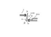
図1及び図4に於て、中央保護部材2の側縁部より側方保護部材3の一方の側縁部36を裏面側1bに配設して重ね合わせて相互に縫着した縦接続ライン23を形成している。
なお、側方保護部材3の一方とは、プロテクター本体1又は中央保護部材2を中心として見た場合に左右内方となる方向である。
図1及び図5に示すように、縦接続ライン23において、中央保護部材2と側方保護部材3との縫着を行なわない縦接続非縫製部位29を形成し、さらに、側方保護部材3の一方の側縁部36の内、縦接続非縫製部位29に対応する部分を、その側方保護部材3の左右内方へ凹設して、表て面側1aと、裏面側1bと、を連通する第1通気窓部21を形成している。In FIG. 1 and FIG. 4, the vertical connection line in which one
In addition, one
As shown in FIGS. 1 and 5, in the
側方保護部材3の一方の側縁部36の内、縦接続非縫製部位29に対応する部分を、その側方保護部材3の左右内方へ凹設することで、第1通気窓部21を前後左右方向に常時開口状態に保持している。つまり、確実に通気が行われるようにしている。なお、側方保護部材3の一方の側縁部36の内、縦接続非縫製部位29に対応する部分は、中央保護部材2の左右外方に凹設されているとも言える。第1通気窓部21は、中央保護部材2の側縁部に沿って2箇所、つまり、プロテクター本体1に合計で4箇所設けている。 Of the one
図1乃至図3於て、側方保護部材3は、相互に縫着される三角形状乃至台形状の上保護片3Aと、矩形状の下保護片3Bと、を有している。言い換えると、側方保護部材3は、上保護片3Aと下保護片3Bに上下方向に分割されている。プロテクター本体1は、中央保護部材2と、左右一対の上保護片3A,3Aと、左右一対の下保護片3B,3Bと、に5分割されているとも言える。 1 to 3, the
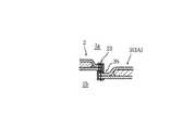
図1及び図7に於て、上保護片3Aの下縁部34より下保護片3Bの上縁部35を裏面側1bに配設して重ね合わせて相互に縫着した水平状(横)接続ライン33を形成している。
そして、図1と図6及び図7に示すように、水平状接続ライン33において、上保護片3Aと下保護片3Bとの縫着を行なわない水平状接続非縫製部位39を形成して、表て面側(外部側)1aと、裏面側(人体側)1bと、を連通する第2通気窓部31を設けている。1 and 7, a horizontal shape (horizontal) in which the
Then, as shown in FIGS. 1, 6, and 7, in the
上述のように、縦接続ライン23において、中央保護部材2の側縁部と、上保護片3Aの一方の側縁部36と、が対応する範囲に、縦接続非縫製部位29(第1通気窓部21)が1箇所形成されている。また、中央保護部材2の側縁部と、下保護片3Bの一方の側縁部36と、が対応する範囲に、縦接続非縫製部位29(第1通気窓部21)が1箇所形成されている(図1及び図2参照)。 As described above, in the
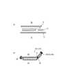
側方保護部材3(上保護片3A及び下保護片3B)は、縫製前の図8(a)の状態から、図8(b)に示すように、表て面側1aの表被覆部材71と、裏面側1bの裏被覆部材72と、表被覆部材71と裏被覆部材72の間に介在される第1緩衝部材(クッション部材)73及び第2緩衝部材74と、を有している。
そして、表被覆部材71より短い裏被覆部材72で、表被覆部材71を裏面側1bへ引っ張り込むように、側方保護部材3の左右方向中間部を縦方向に縫製した屈曲縫製ライン37によって、屈曲部30を形成している。中央保護部材2に縫着される側の側方保護部材3の側縁部を一方の側縁部36と呼ぶと、他方の側縁部38が、自然状態で、左右内方に折れ曲がるように縫製されている。なお、第1緩衝部材73及び第2緩衝部材74は発泡プラスチック樹脂とするのが望ましい。また、表被覆部材71及び裏被覆部材72は、天然又は人工(合成)の皮革や、ナイロン系やポリエステル系の生地とするのが望ましい。As shown in FIG. 8B, the side protection member 3 (the
Then, with the
また、図3及び図7に示すように、上保護片3Aの屈曲部30(30a)と上保護片3Aの他方の側縁部38(38a)の間に、下保護片3Bの屈曲部30(30b)を配設し、縫着(縫製)することで、上保護片3Aの他方の側縁部38(38a)より下保護片3Bの他方の側縁部38(38b)を裏面側1bへ接近するように設けている。つまり、上保護片3Aを下保護片3Bに対して表て面側1aへ撓ませて(膨らませて)縫着し、第2通気窓部31を上下方向に常時開口状態に保持し、確実に通気が行われるようにしている。第2通気窓部31は、1つの側方保護部材3に1箇所設けている。つまり、プロテクター本体1に合計で2箇所設けている。また、上保護片3Aより下保護片3Bをプロテクター本体1の左右外方(後方)へ突出させている。 3 and 7, the
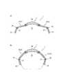
また、図9(a)に示すように、プロテクター本体1の胸部乃至腹部(前腹部及び横腹部)を保護する部分の横断面形状(図1に示す切断線H−Hの断面)を横倒C字乃至横倒コの字状(横倒三日月状)に形成している。また、側方保護部材3の上記横断面形状をへの字状に形成している。 Moreover, as shown to Fig.9 (a), the transverse cross-sectional shape (cross section of the cutting line HH shown in FIG. 1) of the part which protects the chest thru | or abdomen (front abdomen and abdominal abdomen) of the protector
図1に於て、中央保護部材2は、左右一対の突片状肩部25,25に、カップ状(椀型)の肩パット部材5(右肩パット部材5A,左肩パット部材5B)が左右外方に突出状に縫着されている。
中央保護部材2の側縁部より肩パット部材5の一方の側縁部56を表て面側1aに配設して重ね合わせて相互に縫着した肩接続ライン53を形成している。そして、肩接続ライン53において、中央保護部材2と肩パット部材5との縫着を行なわない肩接続非縫製部位59を形成し、表て面側1aと、裏面側1b(人体の肩部側)と、を連通する第3通気窓部51を設けている。第3通気窓部51は、合計で2箇所設けている。なお、肩パット部材5の一方とは、プロテクター本体1又は中央保護部材2を中心として見た場合に左右内方となる方向である。In FIG. 1, the central
One
また、プロテクター本体1には、人体に装着するためのY字状の肩掛け背ベルト部材6及び一文字状の腰ベルト部材7と、が取着されている。装着用のベルト部材(背ベルト部材6及び腰ベルト部材7)は、プロテクター本体1に、雌雄一対のバックル部材を介して着脱自在に取着されている。なお、ベルト部材の形状は自由である。また、背ベルト部材6及び腰ベルト部材7は、図2、図3、図9に於て図示省略している。 The
上述した本発明のプロテクターの使用方法(作用)について説明する。
使用者が、中央保護部材2を胸部及び前腹部に接触すると、図9(a)に示す状態から、側方保護部材3が、図9(b)に、二点鎖線で示した人体の外形状に沿うように揺動し(巻き込んで)、前腹部乃至横腹部の人体の曲部に沿って密着する。また、側方保護部材3は、上保護片3Aが人体の脇下部乃至上横腹部の形状に沿い、下保護片3Bが人体の腰部近傍の下横腹部に沿って、人体の側面の凹凸(曲線)に対応して確実に密着する。さらに、左右の側方保護部材3,3が、屈曲部30によって抱き込み状(挟持状)に人体の外形状に沿うように密着する。The use method (action) of the protector of the present invention described above will be described.
When the user contacts the
即ち、ベルト部材で側方保護部材3(プロテクター本体1)を横腹部から背中側へ引き込むように強く締め付ける必要がなくなり、ベルト部材が使用者を強く圧迫せず、不快感を軽減する。容易かつ迅速に密着状に装着される。また、使用者の運動による位置ズレを確実に防止し、他者や球からの接触を確実に保護する。 That is, it is not necessary to tighten the side protection member 3 (the protector main body 1) with the belt member so that the
第1通気窓部21は、図5に示す矢印61のように、装着時に発生する熱気を裏面側1b(人体の胸部や前腹部及び横腹部)から表て面側1aに送り出す。或いは、矢印62のように、外気を表て面側1aから裏面側1b(人体の胸部や前腹部及び横腹部)に取り込む。
人体の胸部及び前腹部と中央保護部材2の間に左右方向の空気(外気や熱気)の流れをつくり、かつ、人体の横腹部と側方保護部材3の間に前後方向の空気の流れをつくって、人体の胸部及び前腹部や横腹部に冷却効果をもたらす。As shown by an
A flow of air in the left-right direction (outside air or hot air) is created between the chest and front abdomen of the human body and the
第2通気窓部31は、図6に示す矢印63のように、装着時に発生する熱気を裏面側1bから表て面側1aに送り出す。或いは、矢印64のように、外気を表て面側1aから裏面側1bに取り込む。使用者と側方保護部材3の間に、上下方向の空気の流れをつくり、人体の横腹部や脇下に冷却効果をもたらす。 As shown by an
第3通気窓部51は、装着時に発生する熱気を裏面側1b(人体の肩部)から表て面側1aに送り出す。或いは、外気を表て面側1aから裏面側1bに取り込む。使用者と肩パット部材5の間に、左右方向の空気の流れをつくり、人体の肩部に冷却効果をもたらす。 The 3rd
即ち、第1通気窓部21と第2通気窓部31と第3通気窓部51から、装着時に発生する熱気を確実に排出させ、又は、表て面側1aから裏面側1bに外気を侵入させ、蒸れを軽減し、快適にプレーできる。 That is, the
本発明は設計変更可能であって、側方保護部材3は、上保護片3Aと下保護片3Bのような2分割に限らず、上下方向に3分割或いは4分割しても良い。つまり、2分割以上とするも良い。
また、縦接続ライン23において、縦接続非縫製部位29(第1通気窓部21)を、1箇所又、又は、2箇所以上形成するも良い。水平状接続ライン33において、水平状接続非縫製部位39(第2通気窓部31)を、1箇所以上形成するも良い。肩パット部材5は、左右一方のみ、或いは、設けなくとも良い。The design of the present invention can be changed, and the
Further, in the
以上のように、本発明のプロテクターは、人体の胸部及び前腹部を保護する中央保護部材2と、中央保護部材2から左右側方へ突出状に縫着されて人体の横腹部を保護する左右一対の側方保護部材3,3と、を有するので、人体の太さの異なる部位に、立体的に沿うように対応して確実に密着し、前腹部及び横腹部を保護できる。密着性を向上させて位置ズレを防止し、確実に保護できる。ベルト部材(背ベルト部材6や腰ベルト部材7)を強く締め付ける必要がなく、ベルト部材による圧迫や不快感を軽減できる。中央保護部材2と側方保護部材3の縫着により、通気用の窓部(第1・第2通気窓部21,31)を容易に形成することができる。また、中央保護部材2と側方保護部材3とを夫々保護すべき部位に対応した硬さ及び形状に容易に成形できる。例えば、中央保護部材2を強度(硬度)のある押圧成形で設け、側方保護部材3を柔軟性のある縫製によって設けることができる。 As described above, the protector of the present invention includes the central
また、中央保護部材2と上記側方保護部材3とを相互に縫着した縦接続ライン23において、表て面側1aと裏面側1bを連通する第1通気窓部21を、縦接続非縫製部位29によって形成したので、使用者と、中央保護部材2及び側方保護部材3と、の間の蒸れを軽減し、使用者に快適にプレーさせることができる。使用者と、中央保護部材2及び側方保護部材3と、の間から熱気を排出できる。或いは、外気を取り込むことができる。中央保護部材2と側方保護部材3との接続と、第1通気窓部21の形成と、を縫製によって、略同時に(同工程にて)行なうことができ、容易かつ迅速に製造できる。熱気や外気を、人体の前後左右方向に流すようにでき、迅速に効率良く蒸れを防止できる。 Further, in the
また、側方保護部材3は、相互に縫着される上保護片3Aと下保護片3Bとを有し、縫着された水平状接続ライン33において、表て面側1aと裏面側1bを連通する第2通気窓部31を、水平状接続非縫製部位39によって形成したので、使用者に快適にプレーさせることができる。使用者と、側方保護部材3と、の間から熱気を排出できる。或いは、外気を取り込むことができる。上保護片3Aと下保護片3Bとの接続と、第2通気窓部31の形成と、を縫製によって、略同時に(同工程にて)行なうことができ、容易かつ迅速に製造できる。熱気や外気を、人体の上下方向に流すようにでき、迅速に効率良く蒸れを防止できる。上保護片3Aと下保護片3Bとを夫々保護すべき部位に対応した形状に成形でき、密着性を向上させて位置ズレを防止し、確実に保護できる。 Further, the
また、側方保護部材3は、自然状態で、裏面方向へ折れ曲がる屈曲部30を有するので、より確実かつ容易に人体に沿わせて密着させることができる。ベルト部材を強く締め付ける必要がなく、横腹部を包むように裏面方向(左右内方)へ自然と密着状に保護でき、装着時間を短縮できると共に、確実に横腹部を保護できる。 Further, since the
1a 表て面側(外部側)
1b 裏面側(人体側)
2 中央保護部材
3 側方保護部材
3A 上保護片
3B 下保護片
21 第1通気窓部
23 縦接続ライン
29 縦接続非縫製部位
30 屈曲部
31 第2通気窓部
33 水平状接続ライン
39 水平状接続非縫製部位1a Front side (external side)
1b Back side (human body side)
2 Central
21 First ventilation window
23 Vertical connection line
29 Vertical connection non-sewing part
30 Bend
31 Second ventilation window
33 Horizontal connection line
39 Horizontal connection non-sewing part
Claims (1)
Translated fromJapanese上記中央保護部材(2)と上記側方保護部材(3)とを相互に縫着した縦接続ライン(23)において、表て面側(1a)と裏面側(1b)を連通する第1通気窓部(21)を、縦接続非縫製部位(29)によって形成し、
上記側方保護部材(3)は、相互に縫着される上保護片(3A)と下保護片(3B)とを有し、上記縫着された水平状接続ライン(33)において、上記表て面側(1a)と上記裏面側(1b)を連通する第2通気窓部(31)を、水平状接続非縫製部位(39)によって形成することを特徴とするプロテクター。A central protective member (2) that protects the chest and front abdomen of the human body, and a pair of left and right lateral protective members that are sewn in a protruding manner from the central protective member (2) to the left and right sides to protect the lateral abdomen of the human body. and (3) (3),I have a,
In the vertical connection line (23) in which the central protection member (2) and the side protection member (3) are sewn together, the first ventilation that communicates the surface side (1a) and the back surface side (1b). The window (21) is formed by the vertically connected non-sewn part (29),
The side protection member (3) has an upper protection piece (3A) and a lower protection piece (3B) that are sewn to each other. In the sewn horizontal connection line (33), The second vent window portion (31) that connects the front surface side (1a) and the rear surface side (1b) is formed bya horizontal connection non-sewn portion (39) .
Priority Applications (1)
| Application Number | Priority Date | Filing Date | Title |
|---|---|---|---|
| JP2009273596AJP5036794B2 (en) | 2009-12-01 | 2009-12-01 | protector |
Applications Claiming Priority (1)
| Application Number | Priority Date | Filing Date | Title |
|---|---|---|---|
| JP2009273596AJP5036794B2 (en) | 2009-12-01 | 2009-12-01 | protector |
Related Child Applications (1)
| Application Number | Title | Priority Date | Filing Date |
|---|---|---|---|
| JP2012128196ADivisionJP5280565B2 (en) | 2012-06-05 | 2012-06-05 | protector |
Publications (2)
| Publication Number | Publication Date |
|---|---|
| JP2011115267A JP2011115267A (en) | 2011-06-16 |
| JP5036794B2true JP5036794B2 (en) | 2012-09-26 |
Family
ID=44281335
Family Applications (1)
| Application Number | Title | Priority Date | Filing Date |
|---|---|---|---|
| JP2009273596AActiveJP5036794B2 (en) | 2009-12-01 | 2009-12-01 | protector |
Country Status (1)
| Country | Link |
|---|---|
| JP (1) | JP5036794B2 (en) |
Cited By (2)
| Publication number | Priority date | Publication date | Assignee | Title |
|---|---|---|---|---|
| US11202954B2 (en) | 2017-12-21 | 2021-12-21 | Rawlings Sporting Goods Company, Inc. | Hinged leg guard |
| JP7477544B2 (en) | 2022-02-03 | 2024-05-01 | 美津濃株式会社 | Catcher's chest protector |
Families Citing this family (2)
| Publication number | Priority date | Publication date | Assignee | Title |
|---|---|---|---|---|
| JP5852994B2 (en)* | 2013-07-02 | 2016-02-09 | 株式会社二子商事 | Leg guard |
| JP6830677B2 (en)* | 2019-04-09 | 2021-02-17 | 株式会社二子商事 | protector |
Family Cites Families (3)
| Publication number | Priority date | Publication date | Assignee | Title |
|---|---|---|---|---|
| JPS60147475U (en)* | 1984-03-13 | 1985-09-30 | 美津濃株式会社 | Protector for baseball/softball |
| JPH0123507Y2 (en)* | 1984-04-16 | 1989-07-19 | ||
| JP4633144B2 (en)* | 2008-07-02 | 2011-02-16 | ゼット株式会社 | Baseball or softball protector |
- 2009
- 2009-12-01JPJP2009273596Apatent/JP5036794B2/enactiveActive
Cited By (2)
| Publication number | Priority date | Publication date | Assignee | Title |
|---|---|---|---|---|
| US11202954B2 (en) | 2017-12-21 | 2021-12-21 | Rawlings Sporting Goods Company, Inc. | Hinged leg guard |
| JP7477544B2 (en) | 2022-02-03 | 2024-05-01 | 美津濃株式会社 | Catcher's chest protector |
Also Published As
| Publication number | Publication date |
|---|---|
| JP2011115267A (en) | 2011-06-16 |
Similar Documents
| Publication | Publication Date | Title |
|---|---|---|
| US20110252549A1 (en) | Compression undergarment | |
| US8266727B2 (en) | Padding device for sports | |
| JP5036794B2 (en) | protector | |
| US20140020157A1 (en) | Soft safe helmet | |
| JP5280565B2 (en) | protector | |
| JP5192008B2 (en) | protector | |
| ITVR20090030A1 (en) | WEARABLE PROTECTIVE DEVICE. | |
| US2364571A (en) | Boxer's helmet | |
| JP4964924B2 (en) | Leg protection | |
| CN218357266U (en) | Anti-strike protective tool for craniocerebral | |
| JP5775909B2 (en) | Arm guard | |
| JP4734357B2 (en) | protector | |
| JP5356352B2 (en) | Putter for protector | |
| JP4672051B2 (en) | Leg guard for ball game | |
| CN211536479U (en) | Man protects crotch structure for fighting match | |
| JP6449361B2 (en) | protector | |
| PL226220B1 (en) | Protective helmet | |
| JP4700458B2 (en) | Head protection | |
| JP5271297B2 (en) | Batter foot guard | |
| CN106820324A (en) | Human body protection pad | |
| JP2019205544A (en) | Sport protector | |
| JP3133520U (en) | Inner supporter | |
| JP4834117B2 (en) | Baseball calf pad | |
| CN201030205Y (en) | Hip bone protective equipment with air bag | |
| JP2025063399A (en) | Body Mitt |
Legal Events
| Date | Code | Title | Description |
|---|---|---|---|
| A977 | Report on retrieval | Free format text:JAPANESE INTERMEDIATE CODE: A971007 Effective date:20120328 | |
| A131 | Notification of reasons for refusal | Free format text:JAPANESE INTERMEDIATE CODE: A131 Effective date:20120417 | |
| A521 | Request for written amendment filed | Free format text:JAPANESE INTERMEDIATE CODE: A523 Effective date:20120518 | |
| TRDD | Decision of grant or rejection written | ||
| A01 | Written decision to grant a patent or to grant a registration (utility model) | Free format text:JAPANESE INTERMEDIATE CODE: A01 Effective date:20120612 | |
| A01 | Written decision to grant a patent or to grant a registration (utility model) | Free format text:JAPANESE INTERMEDIATE CODE: A01 | |
| A61 | First payment of annual fees (during grant procedure) | Free format text:JAPANESE INTERMEDIATE CODE: A61 Effective date:20120703 | |
| FPAY | Renewal fee payment (event date is renewal date of database) | Free format text:PAYMENT UNTIL: 20150713 Year of fee payment:3 | |
| R150 | Certificate of patent or registration of utility model | Ref document number:5036794 Country of ref document:JP Free format text:JAPANESE INTERMEDIATE CODE: R150 Free format text:JAPANESE INTERMEDIATE CODE: R150 | |
| R250 | Receipt of annual fees | Free format text:JAPANESE INTERMEDIATE CODE: R250 | |
| R250 | Receipt of annual fees | Free format text:JAPANESE INTERMEDIATE CODE: R250 | |
| R250 | Receipt of annual fees | Free format text:JAPANESE INTERMEDIATE CODE: R250 | |
| R250 | Receipt of annual fees | Free format text:JAPANESE INTERMEDIATE CODE: R250 | |
| R250 | Receipt of annual fees | Free format text:JAPANESE INTERMEDIATE CODE: R250 | |
| R250 | Receipt of annual fees | Free format text:JAPANESE INTERMEDIATE CODE: R250 | |
| R250 | Receipt of annual fees | Free format text:JAPANESE INTERMEDIATE CODE: R250 | |
| R250 | Receipt of annual fees | Free format text:JAPANESE INTERMEDIATE CODE: R250 | |
| R250 | Receipt of annual fees | Free format text:JAPANESE INTERMEDIATE CODE: R250 | |
| R250 | Receipt of annual fees | Free format text:JAPANESE INTERMEDIATE CODE: R250 | |
| R250 | Receipt of annual fees | Free format text:JAPANESE INTERMEDIATE CODE: R250 |