JP5033792B2 - Injection device with visual content end indication - Google Patents
Injection device with visual content end indicationDownload PDFInfo
- Publication number
- JP5033792B2 JP5033792B2JP2008514056AJP2008514056AJP5033792B2JP 5033792 B2JP5033792 B2JP 5033792B2JP 2008514056 AJP2008514056 AJP 2008514056AJP 2008514056 AJP2008514056 AJP 2008514056AJP 5033792 B2JP5033792 B2JP 5033792B2
- Authority
- JP
- Japan
- Prior art keywords
- dose
- track
- housing
- reservoir
- injection device
- Prior art date
- Legal status (The legal status is an assumption and is not a legal conclusion. Google has not performed a legal analysis and makes no representation as to the accuracy of the status listed.)
- Expired - Fee Related
Links
- 238000002347injectionMethods0.000titleclaimsdescription33
- 239000007924injectionSubstances0.000titleclaimsdescription33
- 230000000007visual effectEffects0.000titledescription4
- 238000001802infusionMethods0.000claimsdescription21
- 239000007788liquidSubstances0.000claimsdescription13
- 239000003814drugSubstances0.000claimsdescription8
- 230000007246mechanismEffects0.000description8
- 230000033001locomotionEffects0.000description7
- NOESYZHRGYRDHS-UHFFFAOYSA-NinsulinChemical compoundN1C(=O)C(NC(=O)C(CCC(N)=O)NC(=O)C(CCC(O)=O)NC(=O)C(C(C)C)NC(=O)C(NC(=O)CN)C(C)CC)CSSCC(C(NC(CO)C(=O)NC(CC(C)C)C(=O)NC(CC=2C=CC(O)=CC=2)C(=O)NC(CCC(N)=O)C(=O)NC(CC(C)C)C(=O)NC(CCC(O)=O)C(=O)NC(CC(N)=O)C(=O)NC(CC=2C=CC(O)=CC=2)C(=O)NC(CSSCC(NC(=O)C(C(C)C)NC(=O)C(CC(C)C)NC(=O)C(CC=2C=CC(O)=CC=2)NC(=O)C(CC(C)C)NC(=O)C(C)NC(=O)C(CCC(O)=O)NC(=O)C(C(C)C)NC(=O)C(CC(C)C)NC(=O)C(CC=2NC=NC=2)NC(=O)C(CO)NC(=O)CNC2=O)C(=O)NCC(=O)NC(CCC(O)=O)C(=O)NC(CCCNC(N)=N)C(=O)NCC(=O)NC(CC=3C=CC=CC=3)C(=O)NC(CC=3C=CC=CC=3)C(=O)NC(CC=3C=CC(O)=CC=3)C(=O)NC(C(C)O)C(=O)N3C(CCC3)C(=O)NC(CCCCN)C(=O)NC(C)C(O)=O)C(=O)NC(CC(N)=O)C(O)=O)=O)NC(=O)C(C(C)CC)NC(=O)C(CO)NC(=O)C(C(C)O)NC(=O)C1CSSCC2NC(=O)C(CC(C)C)NC(=O)C(NC(=O)C(CCC(N)=O)NC(=O)C(CC(N)=O)NC(=O)C(NC(=O)C(N)CC=1C=CC=CC=1)C(C)C)CC1=CN=CN1NOESYZHRGYRDHS-UHFFFAOYSA-N0.000description5
- 210000004513dentitionAnatomy0.000description4
- 229940079593drugDrugs0.000description4
- 230000036346tooth eruptionEffects0.000description4
- 230000008878couplingEffects0.000description3
- 238000010168coupling processMethods0.000description3
- 238000005859coupling reactionMethods0.000description3
- 239000000243solutionSubstances0.000description3
- 102000004877InsulinHuman genes0.000description2
- 108090001061InsulinProteins0.000description2
- 239000003086colorantSubstances0.000description2
- 206010012601diabetes mellitusDiseases0.000description2
- 230000014509gene expressionEffects0.000description2
- 229940088597hormoneDrugs0.000description2
- 239000005556hormoneSubstances0.000description2
- 229940125396insulinDrugs0.000description2
- 108090000623proteins and genesProteins0.000description2
- 108010075254C-PeptideProteins0.000description1
- 239000013543active substanceSubstances0.000description1
- 239000003795chemical substances by applicationSubstances0.000description1
- 235000015872dietary supplementNutrition0.000description1
- 230000026058directional locomotionEffects0.000description1
- 239000012530fluidSubstances0.000description1
- 239000000499gelSubstances0.000description1
- 238000010348incorporationMethods0.000description1
- 239000000463materialSubstances0.000description1
- 238000000034methodMethods0.000description1
- 238000012986modificationMethods0.000description1
- 230000004048modificationEffects0.000description1
- 230000000149penetrating effectEffects0.000description1
- 239000008194pharmaceutical compositionSubstances0.000description1
- 102000004196processed proteins & peptidesHuman genes0.000description1
- 108090000765processed proteins & peptidesProteins0.000description1
- 102000004169proteins and genesHuman genes0.000description1
- 238000004064recyclingMethods0.000description1
- 239000007787solidSubstances0.000description1
- 238000007920subcutaneous administrationMethods0.000description1
- 238000010254subcutaneous injectionMethods0.000description1
- 239000007929subcutaneous injectionSubstances0.000description1
- 239000000126substanceSubstances0.000description1
- 239000000725suspensionSubstances0.000description1
- 230000037317transdermal deliveryEffects0.000description1
Images


Classifications
- A—HUMAN NECESSITIES
- A61—MEDICAL OR VETERINARY SCIENCE; HYGIENE
- A61M—DEVICES FOR INTRODUCING MEDIA INTO, OR ONTO, THE BODY; DEVICES FOR TRANSDUCING BODY MEDIA OR FOR TAKING MEDIA FROM THE BODY; DEVICES FOR PRODUCING OR ENDING SLEEP OR STUPOR
- A61M5/00—Devices for bringing media into the body in a subcutaneous, intra-vascular or intramuscular way; Accessories therefor, e.g. filling or cleaning devices, arm-rests
- A61M5/178—Syringes
- A61M5/31—Details
- A61M5/315—Pistons; Piston-rods; Guiding, blocking or restricting the movement of the rod or piston; Appliances on the rod for facilitating dosing ; Dosing mechanisms
- A61M5/31533—Dosing mechanisms, i.e. setting a dose
- A61M5/31545—Setting modes for dosing
- A61M5/31548—Mechanically operated dose setting member
- A61M5/3155—Mechanically operated dose setting member by rotational movement of dose setting member, e.g. during setting or filling of a syringe
- A61M5/31553—Mechanically operated dose setting member by rotational movement of dose setting member, e.g. during setting or filling of a syringe without axial movement of dose setting member
- A—HUMAN NECESSITIES
- A61—MEDICAL OR VETERINARY SCIENCE; HYGIENE
- A61M—DEVICES FOR INTRODUCING MEDIA INTO, OR ONTO, THE BODY; DEVICES FOR TRANSDUCING BODY MEDIA OR FOR TAKING MEDIA FROM THE BODY; DEVICES FOR PRODUCING OR ENDING SLEEP OR STUPOR
- A61M5/00—Devices for bringing media into the body in a subcutaneous, intra-vascular or intramuscular way; Accessories therefor, e.g. filling or cleaning devices, arm-rests
- A61M5/178—Syringes
- A61M5/20—Automatic syringes, e.g. with automatically actuated piston rod, with automatic needle injection, filling automatically
- A—HUMAN NECESSITIES
- A61—MEDICAL OR VETERINARY SCIENCE; HYGIENE
- A61M—DEVICES FOR INTRODUCING MEDIA INTO, OR ONTO, THE BODY; DEVICES FOR TRANSDUCING BODY MEDIA OR FOR TAKING MEDIA FROM THE BODY; DEVICES FOR PRODUCING OR ENDING SLEEP OR STUPOR
- A61M5/00—Devices for bringing media into the body in a subcutaneous, intra-vascular or intramuscular way; Accessories therefor, e.g. filling or cleaning devices, arm-rests
- A61M5/178—Syringes
- A61M5/31—Details
- A61M5/315—Pistons; Piston-rods; Guiding, blocking or restricting the movement of the rod or piston; Appliances on the rod for facilitating dosing ; Dosing mechanisms
- A61M5/31533—Dosing mechanisms, i.e. setting a dose
- A61M5/31535—Means improving security or handling thereof, e.g. blocking means, means preventing insufficient dosing, means allowing correction of overset dose
- A61M5/31541—Means preventing setting of a dose beyond the amount remaining in the cartridge
- A—HUMAN NECESSITIES
- A61—MEDICAL OR VETERINARY SCIENCE; HYGIENE
- A61M—DEVICES FOR INTRODUCING MEDIA INTO, OR ONTO, THE BODY; DEVICES FOR TRANSDUCING BODY MEDIA OR FOR TAKING MEDIA FROM THE BODY; DEVICES FOR PRODUCING OR ENDING SLEEP OR STUPOR
- A61M5/00—Devices for bringing media into the body in a subcutaneous, intra-vascular or intramuscular way; Accessories therefor, e.g. filling or cleaning devices, arm-rests
- A61M5/178—Syringes
- A61M5/31—Details
- A61M5/315—Pistons; Piston-rods; Guiding, blocking or restricting the movement of the rod or piston; Appliances on the rod for facilitating dosing ; Dosing mechanisms
- A61M5/31565—Administration mechanisms, i.e. constructional features, modes of administering a dose
- A61M5/31566—Means improving security or handling thereof
- A61M5/31568—Means keeping track of the total dose administered, e.g. since the cartridge was inserted
- A—HUMAN NECESSITIES
- A61—MEDICAL OR VETERINARY SCIENCE; HYGIENE
- A61M—DEVICES FOR INTRODUCING MEDIA INTO, OR ONTO, THE BODY; DEVICES FOR TRANSDUCING BODY MEDIA OR FOR TAKING MEDIA FROM THE BODY; DEVICES FOR PRODUCING OR ENDING SLEEP OR STUPOR
- A61M5/00—Devices for bringing media into the body in a subcutaneous, intra-vascular or intramuscular way; Accessories therefor, e.g. filling or cleaning devices, arm-rests
- A61M5/178—Syringes
- A61M5/31—Details
- A61M5/315—Pistons; Piston-rods; Guiding, blocking or restricting the movement of the rod or piston; Appliances on the rod for facilitating dosing ; Dosing mechanisms
- A61M5/31565—Administration mechanisms, i.e. constructional features, modes of administering a dose
- A61M5/31576—Constructional features or modes of drive mechanisms for piston rods
- A61M5/31583—Constructional features or modes of drive mechanisms for piston rods based on rotational translation, i.e. movement of piston rod is caused by relative rotation between the user activated actuator and the piston rod
Landscapes
- Health & Medical Sciences (AREA)
- Vascular Medicine (AREA)
- Engineering & Computer Science (AREA)
- Anesthesiology (AREA)
- Biomedical Technology (AREA)
- Heart & Thoracic Surgery (AREA)
- Hematology (AREA)
- Life Sciences & Earth Sciences (AREA)
- Animal Behavior & Ethology (AREA)
- General Health & Medical Sciences (AREA)
- Public Health (AREA)
- Veterinary Medicine (AREA)
- Infusion, Injection, And Reservoir Apparatuses (AREA)
Description
Translated fromJapanese技術分野
本発明は、例えば注入ペンのような人間の体に薬剤を供給するための装置に関し、好ましくは、内容量の終了を示す機構を備えているこのような注入デバイスに関する。TECHNICAL FIELD The present invention relates to an apparatus for delivering a medicament to the human body, such as an infusion pen, and preferably to such an infusion device comprising a mechanism indicating the end of the internal volume.
背景技術
本発明の開示では、主に、インシュリンの注入による糖尿病の治療について言及する。しかしそれは、本発明の一使用例にすぎない。BACKGROUND OF THE INVENTION The present disclosure primarily refers to the treatment of diabetes by insulin infusion. However, it is only one example of use of the present invention.
注入ペンは、主に、注入を自ら頻繁に行う必要のある、例えば糖尿病に罹患している使用者のために製作されている。このような注入ペンに対しては多くの要望がある。投与量の設定が、簡単且つ明確でなくてはならず、また、設定された投与量も簡単に読めなくてはならない。誤って設定された投与量の取止め又は変更は最小限の手間でできなくてはならず、投与量を注入したら、投与量設定はゼロに戻らなくてはならない。予め充填された注入ペン、すなわちリザーバが空になると処分される注入ペンの場合には、注入ペンがさらに安価で、リサイクルに適した材料で作られているべきである。 Infusion pens are primarily made for users who need to inject themselves frequently, such as those suffering from diabetes. There are many requests for such injection pens. The dose setting must be simple and clear, and the set dose must be easily readable. Stopping or changing an incorrectly set dose should be made with minimal effort, and once the dose has been injected, the dose setting must return to zero. In the case of prefilled injection pens, i.e. injection pens that are disposed of when the reservoir is empty, the injection pen should be made of a material that is cheaper and suitable for recycling.
投与量設定装置は、ナットと協働するねじ切りされたピストンロッドによって動作するものが多く、その場合、ナットとピストンロッドとは、互いに相対回転することができる。投与量の設定は、ストッパから離れるようにナットをねじ回すことによって行われる。注入の際には、ナット部材がストッパに当接するまでピストンロッドを前進させるように押すことによって、ナットがストッパへと戻される。他の投与量設定装置では、構成要素、つまりナット又はピストンロッドの一方は回転不能に保持されており、もう一方は、設定された投与量に依存する設定された角度だけ回転させることができ、これによりピストンロッドは、ナット部材を通って所定距離だけ前進するようにねじ回される。 Many dose setting devices are operated by a threaded piston rod cooperating with a nut, in which case the nut and piston rod can rotate relative to each other. The dose is set by screwing the nut away from the stopper. During injection, the nut is returned to the stopper by pushing the piston rod forward until the nut member abuts against the stopper. In other dose setting devices, one of the components, i.e. the nut or the piston rod, is held non-rotatable and the other can be rotated by a set angle depending on the set dose, As a result, the piston rod is screwed so as to advance a predetermined distance through the nut member.
米国特許第5480387号明細書は、ピストンロッドがカートリッジ内でプランジャを前進させて、これにより、カートリッジの内容物が放出される注入デバイスを開示している。ピストンロッドが完全に引き出され、プランジャがカートリッジの遠位端部に到達してしまうと、カートリッジは空であって、それ以上の薬剤を放出することはできない。このことを使用者に視覚的に示すためには、ピストンロッドを色でマークし、カートリッジが空になるとこの色が窓から見えるようにすることができる。しかし、これは、カートリッジが空であることを示す表示にすぎず、これ自体は、使用者が投与量の設定を行おうとすることを防止するものではない。またこれは、使用者がカートリッジ内に残っている量より大きな投与量を設定するのを防止するものではないので、特に、使用者が設定した投与量が完全に放出されると信じて自己投薬を行ってしまった場合に、潜在的な危険な状況を招く可能性がある。 U.S. Pat. No. 5,480,387 discloses an injection device in which a piston rod advances a plunger within a cartridge, thereby releasing the contents of the cartridge. Once the piston rod is fully withdrawn and the plunger reaches the distal end of the cartridge, the cartridge is empty and no more drug can be released. To visually indicate this to the user, the piston rod can be marked with a color so that this color can be seen through the window when the cartridge is empty. However, this is only an indication that the cartridge is empty and does not prevent the user from trying to set a dose. This also does not prevent the user from setting a dose higher than the amount remaining in the cartridge, so he believes that the dose set by the user will be completely released and is self-administered. Doing so can lead to potentially dangerous situations.
使用者がカートリッジが空になっていることに気付かない場合、そのような注入デバイスを使用する際に、使用者がリザーバ内に残っている内容量より大きな投与量を設定することができないようにすることが重要である。 If the user is unaware that the cartridge is empty, when using such an infusion device, the user will not be able to set a dose larger than the volume remaining in the reservoir. It is important to.
従来技術による供給装置は、欧州特許第327910号明細書に開示されている。この装置は、ナット部材をねじ回して、ねじ山の付けられたピストンロッドに沿ってハウジング内のストッパから離れる方向にナット部材を上昇させることによって、投与量を設定する注射器を備えている。設定された投与量は、注入ボタンを形成するナット部材の端部を軸線方向に再びストッパと当接するように押し戻すことによって注入される。この移動の際、ピストンロッドはナットによって押し動かされるが、ナットは注入の際、ピストンロッドに対して相対運動しない。ピストンロッドのねじ山が、カートリッジの長さ及び内容量に対応する長さを有しているので、カートリッジは、ナットがねじ山の端部にまでねじ回された時にちょうど空となる。これによって、設定されるべき投与量の大きさは、常にカートリッジ内の残量に制限されるようになる。 A feeding device according to the prior art is disclosed in EP 327910. The device includes a syringe that sets the dosage by screwing the nut member and raising the nut member away from the stopper in the housing along the threaded piston rod. The set dose is injected by pushing back the end of the nut member forming the injection button so as to contact the stopper again in the axial direction. During this movement, the piston rod is pushed by the nut, but the nut does not move relative to the piston rod during injection. Since the thread of the piston rod has a length corresponding to the length and internal volume of the cartridge, the cartridge is just empty when the nut is screwed to the end of the thread. As a result, the size of the dose to be set is always limited to the remaining amount in the cartridge.
別の注入デバイスが、米国特許第6582404号明細書に開示されている。この解決手段によれば、空にすべきリザーバ内の液体量に相当する長さのねじ山を有する作動部材が、投与量設定部材によって囲まれている。作動部材及びこの作動部材のねじ山は、ハウジングに連結している。この作動部材と投与量設定部材との間は、ナット部材が仲立ちしている。ナット部材は、作動部材のねじ山に係合しており且つ投与量設定部材に軸線方向に連結している。投与量を設定するためには、投与量設定エレメントを、作動部材に対して相対的に、注入デバイスのハウジングの外へと回転させる。この回転の際には、投与量設定部材に連結しているナット部材はねじ回されて、設定された投与量に相当する距離だけ、ハウジングに連結しているねじ山を上昇する。設定された投与量を注入する時には、投与量設定部材及び作動部材を回転させてハウジング内へと戻し、この時、ナット部材は、作動部材上の相対位置に留まっている、つまり、ナット部材は作動部材のねじ山に対して相対回転不能に保持されている。よって、ねじ山でのナット部材の位置は常に、設定された投与量の合計に相当し、設定された投与量の合計がリザーバの初期含有量に等しくなった時、ナット部材はトラックの端部と係合し、注入デバイスをロックする。 Another infusion device is disclosed in US Pat. No. 6,582,404. According to this solution, the actuating member having a thread having a length corresponding to the amount of liquid in the reservoir to be emptied is surrounded by the dose setting member. The actuating member and the thread of the actuating member are connected to the housing. A nut member is provided between the actuating member and the dose setting member. The nut member engages the thread of the actuating member and is axially connected to the dose setting member. To set the dose, the dose setting element is rotated out of the housing of the infusion device relative to the actuation member. During this rotation, the nut member connected to the dose setting member is screwed up to raise the thread connected to the housing by a distance corresponding to the set dose. When injecting a set dose, the dose setting member and the actuating member are rotated back into the housing, at which time the nut member remains in a relative position on the actuating member, ie, the nut member is It is held so as not to rotate relative to the thread of the actuating member. Thus, the position of the nut member at the thread always corresponds to the set dose total, and when the set dose total equals the initial content of the reservoir, the nut member is at the end of the track. And lock the injection device.
同様の解決手段が、国際公開第2004/078239号パンフレットに開示されている。この注入ペンは、ねじ切られたピストンロッドを備えており、このピストンロッドは、回転させると、内ねじが切られたナット内でねじ回されて前進する。ピストンロッドのねじ山と嵌合するねじ山を有する作動スリーブは、軸線方向に前進する際、ピストンロッドを回転させる。作動スリーブは、投与量ダイヤルスリーブに連結しており、この投与量ダイヤルスリーブは、ハウジングに対して相対回転して、これにより、投与量を増加させる。投与量ダイヤルスリーブは、投与量を設定するためにはハウジングから外へと回転し、設定された投与量を放出するためには元に戻るように回転する。作動スリーブは、投与量を設定する際には投与量ダイヤルスリーブと共に回転するが、設定された投与量を放出する際には回転が防止されている。作動スリーブのこの非回転運動によって、ピストンロッドが回転せしめられ、内ねじ山においてねじ回されて前進する。投与量ダイヤルスリーブに連結された作動スリーブには、カートリッジ内の液体量に相当するねじ山が設けられている。このねじ山と係合するナットは、ハウジングに軸線方向に連結しており、この場合、ナットは、投与量を設定する際には、ねじ回されて作動部材のねじ山を上昇するが、設定された投与量を注入する際には、その相対位置で回転不能に保持される。よって、ナットの位置は常に、設定された投与量の合計に相当するので、設定された投与量の合計がカートリッジの初期内容量に等しくなった時、ナットがトラックの端部に係合し、注入デバイスをロックする。 A similar solution is disclosed in WO 2004/078239. The injection pen includes a threaded piston rod that, when rotated, is threaded and advanced within an internally threaded nut. An actuating sleeve having a thread that mates with a thread on the piston rod rotates the piston rod as it advances in the axial direction. The actuating sleeve is connected to the dose dial sleeve, which rotates relative to the housing, thereby increasing the dose. The dose dial sleeve rotates out of the housing to set the dose and back to release the set dose. The actuating sleeve rotates with the dose dial sleeve when setting the dose, but is prevented from rotating when releasing the set dose. This non-rotational movement of the actuating sleeve causes the piston rod to rotate and be advanced by being screwed on the inner thread. The working sleeve connected to the dose dial sleeve is provided with a thread corresponding to the amount of liquid in the cartridge. The nut that engages this thread is axially connected to the housing, in which case the nut is screwed up to raise the thread of the actuating member when setting the dosage, When the injected dose is injected, it is held non-rotatable in its relative position. Thus, the position of the nut always corresponds to the total dose set, so when the total set dose equals the initial capacity of the cartridge, the nut engages the end of the track, Lock the infusion device.
上記のような全ての、いわゆる内容量の終了を示す機構は、設定された投与量の合計がリザーバ内の初期の液体量に等しくなった時に、注入デバイスの投与量設定機構をロックするという目的を達成するものである。よってこのようなデバイスの使用者が、リザーバ内に残った液体量より大きな投与量を設定できないようになっている。 All the so-called end-of-volume mechanisms described above are intended to lock the dose setting mechanism of the infusion device when the total dose set is equal to the initial liquid volume in the reservoir. Is achieved. Therefore, the user of such a device cannot set a dose larger than the amount of liquid remaining in the reservoir.
発明の概要
上述の従来技術による装置を考慮し、本発明の課題は、内容量の終了を示す機構を有する薬剤供給装置であって、リザーバ内の残量よりも大きな投与量の設定を防止することに加え、使用者に、内容量が終了に達したことを表示する視覚的表示も提供する装置を提供することである。SUMMARY OF THE INVENTION In view of the above-described prior art device, the object of the present invention is a drug supply device having a mechanism for indicating the end of the internal volume, which prevents the setting of a dose larger than the remaining amount in the reservoir In addition, it is to provide a device that also provides the user with a visual indication that the content has reached the end.
請求項1
ハウジングと、このハウジングに対して相対回転して投与量を設定する投与量設定部材とを備えている注入デバイスにおいて、らせん状のねじ山等のトラックが、ハウジング又は投与量設定部材のどちらかに連結可能であり、ナット部材等のトラックフォロワが、前記2つの部材のもう一方と連結可能である。Claim 1
In an infusion device comprising a housing and a dose setting member that rotates relative to the housing to set a dose, a spiral thread or other track is located on either the housing or the dose setting member. A track follower such as a nut member can be connected to the other of the two members.
投与量を設定する際には、トラック及びトラックフォロワは互いに相対回転し、これによりトラックフォロワが、トラックに沿って、設定された投与量に相当する距離だけねじ回される。
この連結は直接的である必要はないが、投与量を設定する際にトラックフォロワがトラックに対して相対回転するのであれば、別のエレメント群を介して行ってもよい。In setting the dose, the track and the track follower rotate relative to each other so that the track follower is screwed along the track by a distance corresponding to the set dose.
This connection does not have to be direct, but may be performed via another group of elements if the track follower rotates relative to the track when setting the dose.
投与量を注入する際には、トラック及びトラックフォロワは、これらを同時に移動させるか又は全く動かさないようにすることによって、相対回転不能に保持される。
トラックフォロワがねじ山におけるその相対位置で保持されるので、トラックフォロワの位置は常に、設定された投与量の合計を表すようになる。
トラックフォロワは、リザーバ内の初期の液体量に相当するトラックの長さを有することによって、設定された投与量の合計がリザーバ内の初期の液体量に達した時に、トラックの端部壁に当接するようになっている。When injecting a dose, the track and track follower are held relatively unrotatable by moving them simultaneously or not moving at all.
Since the track follower is held at its relative position in the thread, the position of the track follower will always represent the set dose total.
The track follower has a track length that corresponds to the initial volume of liquid in the reservoir, so that when the total set dose reaches the initial volume of liquid in the reservoir, the track follower strikes the end wall of the track. It comes to touch.
注入デバイスは通常、投与量設定機構を有し、投与量を注入する前に使用者が投与量を回すことにより増加又は減少させることができるようになっているので、トラックフォロワの位置は、投与量を注入する際の位置となり、よって、この位置は、注入された投与量を示す。 Since the infusion device typically has a dose setting mechanism that allows the user to increase or decrease the dose by turning the dose before injecting the dose, the track follower position is This is the position at which to inject the volume, so this position indicates the dose that was injected.
トラックフォロワが見える透明領域を有するハウジングを設けることによって、使用者が、トラックにおけるトラックフォロワの位置を点検し、これにより、設定された投与量の合計を視覚的に認識することができるようになる。
この領域は、例えばハウジングに設けられた開口部又は透明領域であってよく、この領域を通して、使用者がトラックフォロワを見ることができるか又は少なくともトラックフォロワに設けられたカラー表示を見ることができる。By providing a housing with a transparent area where the track follower can be seen, the user can check the position of the track follower on the track and thereby visually recognize the total dose set. .
This area may be, for example, an opening or a transparent area provided in the housing, through which the user can see the track follower or at least see the color indication provided on the track follower. .
請求項2
トラックフォロワには、例えば、カラー又は同様の表示が設けられていてよく、この場合使用者は、前記ハウジングに設けられている領域を通して視覚的な表示を得ることができる。このカラー表示は、様々な色又は様々な強さで形成されていてよく、この場合、使用者に提供される視覚的な印象が、トラックフォロワのトラックでの位置及びハウジングにおける領域の位置に応じて変化するようになっている。
カラー表示の代わりに、他の表示手段、例えば数字、文字又は簡単な記号を使用することもできる。
The track follower may be provided with, for example, a color or similar indication, in which case the user can obtain a visual indication through an area provided in the housing. This color display may be formed in different colors or different intensities, in which case the visual impression provided to the user depends on the position of the track follower in the track and the position of the area in the housing. Change.
Instead of a color display, other display means such as numbers, letters or simple symbols can be used.
請求項3
米国特許6582404号明細書及び国際公開第2004/078239号パンフレットに開示の内容量の終了を示す機構では、投与量設定部材は、投与量を設定する際には、ハウジング内における固定されたストッパから離れるように回転せしめられ、投与量を注入する際には、固定されたストッパへと戻される。Claim 3
In the mechanism for indicating the end of the internal volume disclosed in US Pat. No. 6,582,404 and International Publication No. WO 2004/078239, the dose setting member can be moved from a fixed stopper in the housing when setting the dose. It is rotated away and returned to a fixed stopper when injecting a dose.
参照により本願に組み込まれ、有利には、米国特許第6004297号明細書の図15〜17に開示されている注入デバイス内に組み込むことができる米国特許第6582404号明細書では、投与量を注入する際、投与量設定部材は回転せしめられ初期の位置へと戻される。 In US Pat. No. 6,582,404, which is incorporated herein by reference and advantageously can be incorporated into the infusion device disclosed in FIGS. 15-17 of US Pat. No. 6,00429797, a dose is infused. At this time, the dose setting member is rotated and returned to the initial position.
参照により本願に組み込まれる国際公開第2004/078239号パンフレットでも、投与量を注入する際、投与量設定部材が回転せしめられ後退するが、トラックを押し動かし且つ投与量設定部材に連結されている作動部材は、軸線方向にその初期位置へ戻される。 Also in WO 2004/078239, which is incorporated herein by reference, when injecting a dose, the dose setting member is rotated and retracted, but the operation that pushes the track and is connected to the dose setting member The member is returned to its initial position in the axial direction.
請求項4及び5
トラックが投与量設定部材に、例えば国際公開第2004/078239号パンフレットに記載されているような作動部材を介して連結されている場合には、投与量設定部材がその初期位置へと戻された時、前記領域は、トラックの端部の位置に位置していることが望ましい。Claims 4 and 5
When the truck is connected to the dose setting member via an actuating member, for example as described in WO 2004/078239, the dose setting member has been returned to its initial position In some cases, the area is located at the end of the track.
請求項6
使用者がそれを通してトラックフォロワを点検することができる透明の領域は、例えばピストンロッドに平行な方向に、ねじ山の一部分に延びていることが可能であり、この場合には、トラックフォロワの長手方向の移動を、トラックの端部に到達するまで、より長い時間に亘って目で確認することができる。
前記透明の領域には、残っている内容量を使用者に知らせる目盛が設けられていてもよい。この目盛は、数字を使用した従来の目盛であってもよいし、他の記号又は異なる色を使用した目盛であってもよい。Claim 6
The transparent area through which the user can inspect the track follower can extend to a part of the thread, for example in a direction parallel to the piston rod, in this case the length of the track follower Directional movement can be visually observed for a longer time until it reaches the end of the track.
The transparent area may be provided with a scale for notifying the user of the remaining content. This scale may be a conventional scale using numbers, or a scale using other symbols or different colors.
請求項7
例えば、作動部材がピストンロッドガイドを介してハウジングに連結されている米国特許第6582404号明細書に記載のように、ねじ山がハウジングに連結されている場合、投与量設定部材に開口部のような追加的な透明の領域を設ける必要がある場合もあり、これにより、使用者がトラックフォロワを視覚的に点検することができるようになる。Claim 7
For example, if the thread is connected to the housing, such as in US Pat. No. 6,582,404, where the actuating member is connected to the housing via a piston rod guide, the dose setting member is like an opening. Additional transparent areas may need to be provided, which allows the user to visually inspect the track follower.
請求項8及び9
投与量設定部材の軸線方向の移動がなく、トラックが、好ましくはハウジングの内部に設けられている場合には、前記領域は、トラックの端部に設けられていることが望ましく、その場合、設定された投与量の合計がリザーバ内の初期の液体量に達し始める時に、トラックフォロワが見えるようになっている。
If there is no axial movement of the dose setting member and the track is preferably provided inside the housing, the region is preferably provided at the end of the track, in which case the setting is The track follower is visible when the total dose administered begins to reach the initial liquid volume in the reservoir.
定義
「注入ペン」は通常、機械的な、つまり使用者によって駆動される注入装置を意味し、筆記用のペンにやや類似の縦長の又は細長い形状を有する。このようなペンは、通常管状の断面を有しているが、この装置は、単に三角形、長方形又は正方形といった異なる断面を有していてもよい。Definitions An “injection pen” usually refers to an injection device that is mechanical, ie, driven by a user, and has an elongated or elongated shape somewhat similar to a writing pen. Such pens typically have a tubular cross section, but the device may simply have a different cross section such as a triangle, rectangle or square.
本明細書で使用される限りでは、「薬剤」という語は、液体、溶液、ゲル又は微細な懸濁液のような、中空の針等の供給手段内を制御下で通過することができる薬剤を含有する流動性の医薬品を包含することを意味する。代表的な薬剤には、ペプチド、たんぱく質(例えば、インスリン、インスリンアナログ及びC−ペプチド)、ホルモン、生物学的に誘導された又は活性物質、ホルモン及び遺伝子ベースの薬剤、栄養補助食品、並びに固体(懸濁された)又は液体状態の別の物質等の医薬製剤を含む。 As used herein, the term “medicament” refers to an agent that can pass under control through a supply means such as a hollow needle, such as a liquid, solution, gel or fine suspension. Is meant to encompass fluid pharmaceuticals containing. Exemplary drugs include peptides, proteins (eg, insulin, insulin analogs and C-peptides), hormones, biologically derived or active substances, hormone and gene-based drugs, dietary supplements, and solids ( A pharmaceutical formulation such as another substance in a suspended or liquid state.
さらに、「皮下」注入という語は、対象に経皮的に供給する任意の方法を包含することを意図している。 Furthermore, the term “subcutaneous” infusion is intended to encompass any method of transdermal delivery to a subject.
さらに、「注射針」は、液体を供給する又は取り出すことを目的として、対象の皮膚を貫通する貫通部材を定義する。 Furthermore, an “injection needle” defines a penetrating member that penetrates the subject's skin for the purpose of supplying or removing liquid.
本明細書に引用された出願公開、特許出願及び特許を含むすべての参考文献は、あたかも各参考文献が個別に且つ具体的に表示されたのと同程度に、参照によりその内容全体が本明細書に組み込まれている。
すべての見出し及び副見出しは本明細書に便宜上使用されているに過ぎず、決して本発明を制限するものでない。All references, including published applications, patent applications and patents cited herein, are hereby incorporated by reference in their entirety as if each reference had been individually and specifically displayed. Embedded in the book.
All headings and subheadings are used herein for convenience only and do not limit the invention in any way.
本明細書に記載した、全ての実施例又は例示的表現(例えば、「等の」)は、単に本発明を分かり易くするために使用しているのであって、特に断らない限り、本発明の範囲を制限するものではない。本明細書内のいかなる用語も、本発明の実施に欠かせない、請求項に記載されていない要素と解釈すべきではない。本明細書における特許文献の引用及び組み込みは、便宜上行っているに過ぎず、そのような特許文献の有効性、特許性及び/又は権利の施行可能性に対するいかなる見解をも反映するものではない。
本発明は、適用法の許す範囲において、特許請求の範囲に記載されている主題の修正物及び均等物を含む。All examples or exemplary representations (e.g., “etc.”) described herein are merely used to make the present invention easier to understand and unless otherwise indicated, It does not limit the range. No language in the specification should be construed as an unclaimed element as essential to the practice of the invention. The citation and incorporation of patent documents herein is done for convenience only and does not reflect any view of the validity, patentability, and / or enforceability of such patent documents.
This invention includes modifications and equivalents of the subject matter recited in the claims appended hereto as permitted by applicable law.
発明の詳細な説明
本発明を、好ましい態様と関連させ図面を参照しながら、以下においてより詳細に説明する。
図面は、概略的であり且つ明確化のために簡略されており、本発明を理解する上で重要な細部のみを示し、それ以外の細部は省略している。全図面を通して、同一又は対応する部材に対しては同じ参照番号を使用している。DETAILED DESCRIPTION OF THE INVENTION The present invention is described in more detail below with reference to the drawings in connection with preferred embodiments.
The drawings are schematic and simplified for clarity, showing only those details that are important to understanding the invention, and omitting other details. Throughout the drawings, the same reference numerals are used for identical or corresponding parts.
以下、「上」及び「下」、「右」及び「左」、「水平」及び「垂直」、「時計回り」及び「反時計回り」といった語又はこれらに類する相対関係を表す表現を使用する場合には、これらの語や表現は、添付図面においてのみ用いられるものであって、実際の使用状況において用いられるものではない。図示の図面は概略的に表されたものであり、それは、様々な構造の構成並びに相対寸法が、例示という目的のみを果たすことを意図しているからである。 Hereinafter, terms such as “upper” and “lower”, “right” and “left”, “horizontal” and “vertical”, “clockwise” and “counterclockwise”, or similar expressions are used. In some cases, these terms and expressions are used only in the accompanying drawings, and are not used in actual use situations. The drawings shown are diagrammatically represented because the various structural configurations and relative dimensions are intended to serve illustrative purposes only.
これらを考慮すると、添付図面における「遠位端部」という語は、注射針が設けられている注入デバイスの端部を指し、一方「近位端部」という語は、注射針から離れる方を向く反対側の端部を指している。 In view of these, the term “distal end” in the accompanying drawings refers to the end of the infusion device where the needle is provided, while the term “proximal end” refers to the side farther from the needle. It points to the opposite end facing away.
図1に、注入デバイス1、好ましくは皮下注入のための注入ペンの投与量設定及び注入機構の断面図を示す。注入デバイス1は、注入デバイス1の中心軸線を中心として回転するようになっている投与量設定部材20を備えている。注入デバイス1は更に、円筒状投与量表示部30、ねじ切りピストンロッド40、中心軸線に沿ってピストンロッド40を動かすようになっている作動部材50、中心軸線に沿って且つこれと同軸に延びるコイルばね60、並びにハウジング70を備えている。 FIG. 1 shows a cross-sectional view of an injection device 1, preferably an injection pen dose setting and injection mechanism for subcutaneous injection. The injection device 1 includes a
投与量設定部材20は、キー溝22に対するキー32の結合によって、円筒状投与量表示部30に係合している。投与量設定部材20の中心軸線を中心とした回転が円筒状投与量表示部30の中心軸線を中心とした回転を生じさせること及びその逆が、このキー32/キー溝22結合によって保証される。さらに、このキー32/キー溝22結合によって、投与量設定部材20及び円筒状投与量表示部30が、中心軸線にほぼ平行な方向で互いに相対摺動できるように可動であることが保証される。 The
同様に作動部材50は、作動部材50のねじ切り部分53によってピストンロッド40の外ねじ部分41に係合している。
円筒状投与量表示部30にはねじ切り部分31が設けられており、このねじ切り部分31は、作動部材50のねじ切り部分51に係合している。Similarly, the operating
The cylindrical
注入デバイス1にはさらに、ロック状態と非ロック状態との間で切替え可能なロック部材80が設けられている。このロック部材80がロック状態にある時(図1Bに図示)、ロック部材80は、例えば作動部材50と相互作用する部分81を有することによって、作動部材50の中心軸線を中心とした回転を防止する。一方、ロック部材80が非ロック状態にある時には、作動部材50は、中心軸線を中心に自由に回転することができる。投与量設定部材20は、歯列結合25/75を介してハウジング70に固定されている。歯列結合25/75によって、投与量設定部材20及びハウジング70を互いに相対回転可能に動かすことができる。しかし、コイルばね60が、投与量設定部材20に軸線方向の力を提供し、歯列25を歯列75の方に向かってハウジング70内部に押し付け、これにより、投与量設定部材20は任意の設定位置に留まる。 The injection device 1 is further provided with a locking
注入デバイス1は、好ましくは以下のように操作される。投与量を設定する時には、ロック部材80をそのロック状態に切り替える。大抵の場合ロック状態は、ロック部材80の初期位置である。続いて使用者は、投与量設定部材20の突起部分21を回すことによって、投与量設定部材20を中心軸線を中心として回転させる。投与量設定部材20と円筒状投与量表示部30との間のキー32/キー溝22結合によって、円筒状投与量表示部30も、中心軸線を中心として回転せしめられる。円筒状投与量表示部30のねじ切り部分31は作動部材50のねじ切り部分51に係合しているので、この回転により、円筒状投与量表示部30は、中心軸線に対して平行な方向に、投与量設定部材20の突起部分21に向かって押しやられる。よって、円筒状投与量表示部30は、投与量設定部材20と円筒状投与量表示部30との間のキー32/キー溝22結合に沿って摺動して移動する。この移動によって、コイルばね60が圧縮され、これにより、ばね60にエネルギーが保存される。よって、投与量設定部材20の外方への移動がないことを含め、注入デバイス1の外観を何ら変えることなく投与量が設定される。 The injection device 1 is preferably operated as follows. When setting the dosage, the
円筒状投与量表示部30には、一群の数字(図示せず)が付けられている。円筒状投与量表示部30が投与量設定部材20の突起部分21の方に向かって移動する際、これらの数字は、作動部材50に設けられている窓52を通して逐次的に見ることができ、これにより、設定された投与量が表示される。注入デバイス1の使用者が円筒状投与量表示部30上の数字を見られるように、ハウジング70には、作動部材50に設けられた窓52と位置整合しているベルト状の窓が設けられている。 A group of numbers (not shown) is attached to the cylindrical
所望の投与量を設定したら、投与量設定部材20の突起部分21の反対側に位置する注射針(図示せず)を使用者の皮膚に挿入する。次に、ロック部材80を非ロック状態に切り替え、これにより、作動部材50が中心軸線を中心として回転できるようにする。圧縮されたコイルばね60に保存されたエネルギーによって、円筒状投与量表示部30が、軸線方向にその初期位置に向かって、つまり投与量設定部材20の突起部分21から離れる方向に押しやられる。作動部材50のねじ切り部分51及び筒状投与量表示部30のねじ切り部分31によって、作動部材50は、中心軸線を中心として回転せしめられる。作動部材50及びそのねじ山53が回転すると、ハウジング70とピストンロッド40との間のキー結合14があるので、キーが設けられているピストンロッド40は、カートリッジ2内を前進する。ピストンロッド40の、突起部分21から離れる方向への軸線方向の移動により、設定された所望の投与量が注入デバイス1から吐出される。 When the desired dose is set, an injection needle (not shown) located on the opposite side of the protruding
あるいは作動部材50が、ピストンロッド40とのキー/キー溝結合をさらに備え、ハウジング70とピストンロッド40とのキー/キー溝結合14を、ねじ山で置き換えてもよい。この場合、ロック部材がその非ロック状態に切り替えられると、ピストンロッド40は中心軸線を中心として回転する。この回転運動によって、ピストンロッドは、中心軸線に平行な方向で投与量設定部材20の突起部分21から離れる方向にねじ回される。この運動によって、注入デバイス1から投与量が吐出される。 Alternatively, the actuating
投与量が吐出された後には、注入デバイス1の様々な部品は、投与量が吐出されたことによってピストンロッド40が投与量設定部材20の突起部分21から離れる方向に移動したこと並びに作動部材50の角度位置がハウジング70に対して相対的に変化したことを除き、それらの初期位置に再び戻っている。よってこの時、注入デバイス1は新たな投与量を設定するための準備ができている。 After the dose has been discharged, the various parts of the infusion device 1 have moved the
さらに、内容量の終了を示す機構を、図2〜4に関連させて説明する。
図2に、長手方向の隆起部分23を有する投与量設定部材20を開示する。この隆起部分23は、内部表面でキー溝22を形成している。このようなキー溝22を1つ以上設けることができる。Further, a mechanism for indicating the end of the internal capacity will be described with reference to FIGS.
FIG. 2 discloses a
図3に、内表面に設けられた内部トラック91及び外表面に設けられたねじ山92を有するナット部材90を開示する。ねじ山92が及ぶのは外表面の360度未満であってよく、これにより、外表面のねじ山のない部分93が残される。 FIG. 3 discloses a
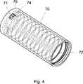
図4に、開口部71と内表面に設けられている内ねじ山72とを有するハウジング70の一部を開示する。
ナット部材90は、図1に開示したように、投与量設定部材20とハウジング70との間を仲立ちしており、内部トラック91は隆起部分23と、ねじ山92はハウジング70の内ねじ山72と係合している。FIG. 4 discloses a portion of a
As shown in FIG. 1, the
投与量設定部材20を回転させることによって投与量を設定する時には、ナット部材90は回転し、設定される投与量に相当する長さだけ内ねじ山72に沿って上昇する。
ばね60を開放することによって設定された投与量を注入する時には、投与量設定部材20が動かされないので、ナット部材90はその位置に留まる。よって、ナット部材90の内ねじ山72における位置は、常時、設定された投与量の合計を表すものとなる。When the dose is set by rotating the
When injecting a dose set by opening the
内ねじ山72は、ピストンロッド40がリザーバ2を空にするために動かなくてはならない長さに相当する長さを有し、リザーバが空になった時には、ねじ山92上のストッパ94が内ねじ山72上の端部壁74に係合するようになっており、これにより、投与量の設定動作を固定化し、使用者が回すことによりリザーバの残りの内容量よりも大きく投与量を増加させてしまうことを防止する。
この端部位置では、ナット部材90を透明領域71から見ることができ、これにより、リザーバが空になったことが使用者に知らされるようになっている。The
At this end position, the
以上、いくつかの好ましい態様を記載したが、本発明はこれらの態様に限定されることはなく、添付の特許請求の範囲で規定される対象の範囲内の他の手法で実施することができることを強調しておく。 While several preferred embodiments have been described above, the present invention is not limited to these embodiments and can be implemented in other ways within the scope of the subject matter defined in the appended claims. To emphasize.
Claims (7)
Translated fromJapanese− 前記リザーバ(2)を支持するハウジング(70)と、
− 投与量を設定するために、前記ハウジング(70)に対して相対回転する投与量設定部材(20)と、
− 前記ハウジング(70)の内側に設けられたトラック(72)であって、前記リザーバ内の液体の初期量に対応する長さを規定する端部壁(74)を有するトラック(72)と、
− 前記ハウジング(70)及び前記投与量設定部材(20)に連結しているトラックフォロワ(90)であって、前記トラック(72)に係合しているトラックフォロワ(90)を備えており、
前記トラック(72)および前記トラックフォロワ(90)が、投与量を設定する際には互いに相対回転し、設定された投与量を注入する際には相対回転不能に保持され、前記トラックフォロワ(90)が、投与量を設定する際に前記トラック(72)に沿って移動し、トラック(72)での、設定された量の合計を表す位置を有し、
前記設定された投与量の合計が前記リザーバ(2)内の液体の初期量に等しくなった時、前記トラックフォロワ(90)が前記トラック(72)の端部壁(74)に係合し、これにより使用者が、前記リザーバ(2)内に残っている内容量より大きな投与量を設定することを防止する注入デバイスにおいて、
前記ハウジング(70)に透明な領域(71)が設けられており、該領域で前記トラックフォロワ(90)を目で確認できることを特徴とする注入デバイス。An infusion device (1) for dispensing a set dose of a liquid medicament from a reservoir (2),
A housing (70) supporting the reservoir (2);
A dose setting member (20) that rotates relative to the housing (70) to set a dose;
A track (72)provided inside the housing (70) having an end wall (74) defining a length corresponding to an initial amount of liquid in the reservoir;
A track follower (90) connected to the housing (70)and the dose setting member (20), the track follower (90) engaging the track (72);
The track (72) and the track follower (90) rotate relative to each other when setting a dose, and are held relatively non-rotatable when injecting a set dose, and the track follower (90 ) Moves along the track (72) in setting the dose, and has a position representing the sum of the set amount in the track (72),
When the set dose total is equal to the initial amount of liquid in the reservoir (2), the track follower (90) engages the end wall (74) of the track (72); In an infusion device which prevents the user from setting a dose larger than the content remaining in the reservoir (2) thereby
The injection device, wherein the housing (70) is provided with a transparent region (71), and the track follower (90) can be visually confirmed in the region.
Applications Claiming Priority (3)
| Application Number | Priority Date | Filing Date | Title |
|---|---|---|---|
| EP05104671 | 2005-05-31 | ||
| EP05104671.2 | 2005-05-31 | ||
| PCT/EP2006/062407WO2006128794A2 (en) | 2005-05-31 | 2006-05-18 | Injection device with visual end-of-content indication |
Publications (2)
| Publication Number | Publication Date |
|---|---|
| JP2008541907A JP2008541907A (en) | 2008-11-27 |
| JP5033792B2true JP5033792B2 (en) | 2012-09-26 |
Family
ID=34940028
Family Applications (1)
| Application Number | Title | Priority Date | Filing Date |
|---|---|---|---|
| JP2008514056AExpired - Fee RelatedJP5033792B2 (en) | 2005-05-31 | 2006-05-18 | Injection device with visual content end indication |
Country Status (5)
| Country | Link |
|---|---|
| US (1) | US9114211B2 (en) |
| EP (1) | EP1907031A2 (en) |
| JP (1) | JP5033792B2 (en) |
| CN (1) | CN101184519B (en) |
| WO (1) | WO2006128794A2 (en) |
Cited By (15)
| Publication number | Priority date | Publication date | Assignee | Title |
|---|---|---|---|---|
| US8945063B2 (en) | 2009-03-20 | 2015-02-03 | Antares Pharma, Inc. | Hazardous agent injection system |
| US9393367B2 (en) | 2013-03-12 | 2016-07-19 | Antares Pharma, Inc. | Prefilled syringes and kits thereof |
| US9486583B2 (en) | 2012-03-06 | 2016-11-08 | Antares Pharma, Inc. | Prefilled syringe with breakaway force feature |
| US9561333B2 (en) | 2008-08-05 | 2017-02-07 | Antares Pharma, Inc. | Multiple dosage injector |
| US9629959B2 (en) | 2005-01-24 | 2017-04-25 | Antares Pharma, Inc. | Prefilled syringe jet injector |
| US9707354B2 (en) | 2013-03-11 | 2017-07-18 | Antares Pharma, Inc. | Multiple dosage injector with rack and pinion dosage system |
| US9737670B2 (en) | 2002-02-11 | 2017-08-22 | Antares Pharma, Inc. | Intradermal injector |
| US9744302B2 (en) | 2013-02-11 | 2017-08-29 | Antares Pharma, Inc. | Needle assisted jet injection device having reduced trigger force |
| US9808582B2 (en) | 2006-05-03 | 2017-11-07 | Antares Pharma, Inc. | Two-stage reconstituting injector |
| US9867949B2 (en) | 2008-03-10 | 2018-01-16 | Antares Pharma, Inc. | Injector safety device |
| US9950125B2 (en) | 2012-04-06 | 2018-04-24 | Antares Pharma, Inc. | Needle assisted jet injection administration of testosterone compositions |
| US10279131B2 (en) | 2011-07-15 | 2019-05-07 | Antares Pharma, Inc. | Injection device with cammed RAM assembly |
| US10357609B2 (en) | 2012-05-07 | 2019-07-23 | Antares Pharma, Inc. | Needle assisted jet injection device having reduced trigger force |
| US10543316B2 (en) | 2006-05-03 | 2020-01-28 | Antares Pharma, Inc. | Injector with adjustable dosing |
| US10568809B2 (en) | 2011-07-15 | 2020-02-25 | Ferring B.V. | Liquid-transfer adapter beveled spike |
Families Citing this family (63)
| Publication number | Priority date | Publication date | Assignee | Title |
|---|---|---|---|---|
| US6663602B2 (en) | 2000-06-16 | 2003-12-16 | Novo Nordisk A/S | Injection device |
| ATE444090T1 (en) | 2004-10-21 | 2009-10-15 | Novo Nordisk As | SELECTION MECHANISM FOR A ROTARY PIN |
| US20090043264A1 (en) | 2005-04-24 | 2009-02-12 | Novo Nordisk A/S | Injection Device |
| ATE458517T1 (en) | 2006-05-16 | 2010-03-15 | Novo Nordisk As | TRANSMISSION MECHANISM FOR AN INJECTION DEVICE |
| JP5253387B2 (en) | 2006-05-18 | 2013-07-31 | ノボ・ノルデイスク・エー/エス | Injection device with mode locking means |
| EP2037999B1 (en) | 2006-07-07 | 2016-12-28 | Proteus Digital Health, Inc. | Smart parenteral administration system |
| HUE060243T2 (en) | 2006-09-15 | 2023-02-28 | Ypsomed Ag | Injection device comprising an improved delivery element |
| BRPI0809265A2 (en)* | 2007-03-23 | 2014-10-07 | Novo Nordisk As | INJECTION DEVICE INCLUDING A TIGHTENING NUT |
| US9108006B2 (en) | 2007-08-17 | 2015-08-18 | Novo Nordisk A/S | Medical device with value sensor |
| US9125979B2 (en) | 2007-10-25 | 2015-09-08 | Proteus Digital Health, Inc. | Fluid transfer port information system |
| CA2707820A1 (en)* | 2007-12-31 | 2009-07-09 | Novo Nordisk A/S | Electronically monitored injection device |
| US8647309B2 (en) | 2008-05-02 | 2014-02-11 | Sanofi-Aventis Deutschland Gmbh | Medication delivery device |
| US8187233B2 (en) | 2008-05-02 | 2012-05-29 | Sanofi-Aventis Deutschland Gmbh | Medication delivery device |
| RU2496528C2 (en) | 2008-05-02 | 2013-10-27 | Санофи-Авентис Дойчланд Гмбх | Drug feeder |
| US12097357B2 (en) | 2008-09-15 | 2024-09-24 | West Pharma. Services IL, Ltd. | Stabilized pen injector |
| US9457148B2 (en) | 2009-04-01 | 2016-10-04 | Shl Group Ab | Medicament delivery device |
| EP2451508B1 (en)* | 2009-07-08 | 2013-11-06 | Novo Nordisk A/S | Frost protected injection device |
| GB0918145D0 (en) | 2009-10-16 | 2009-12-02 | Owen Mumford Ltd | Injector apparatus |
| EP2496290B1 (en) | 2009-11-03 | 2017-01-04 | Sanofi-Aventis Deutschland GmbH | Assembly for a drug delivery device and drug delivery device |
| WO2011060786A1 (en)* | 2009-11-20 | 2011-05-26 | Moeller Claus Schmidt | Spring actuated dose delivery device |
| JP5650755B2 (en) | 2009-12-16 | 2015-01-07 | ベクトン・ディキンソン・アンド・カンパニーBecton, Dickinson And Company | Self injection device |
| CN104353151B (en)* | 2009-12-16 | 2018-07-20 | 贝克顿·迪金森公司 | Injection device |
| BR112012019212A2 (en) | 2010-02-01 | 2017-06-13 | Proteus Digital Health Inc | data collection system |
| EP2531096A4 (en) | 2010-02-01 | 2013-09-11 | Proteus Digital Health Inc | Two-wrist data gathering system |
| US12350474B2 (en) | 2011-03-16 | 2025-07-08 | Becton, Dickinson And Company | Multiple use disposable injection pen |
| EP3878495B1 (en) | 2011-03-16 | 2024-06-12 | Becton, Dickinson and Company | Multiple use disposable injection pen |
| US11577029B2 (en) | 2012-03-15 | 2023-02-14 | Becton, Dickinson And Company | Multiple use disposable injection pen |
| JP6069351B2 (en) | 2011-12-29 | 2017-02-01 | ノボ・ノルデイスク・エー/エス | Torsion spring type automatic syringe with dial-up / dial-down administration mechanism |
| US8834449B2 (en) | 2012-01-23 | 2014-09-16 | Ikomed Technologies, Inc. | Mixing syringe |
| US9751056B2 (en) | 2012-01-23 | 2017-09-05 | Merit Medical Systems, Inc. | Mixing syringe |
| CA2866478C (en)* | 2012-02-13 | 2019-07-23 | Radius Engineering Inc. | Reusable cartridge for injection molding |
| JP6336401B2 (en)* | 2012-02-21 | 2018-06-06 | ノボ・ノルデイスク・エー/エス | Dose end indicator |
| CH706567A2 (en) | 2012-05-16 | 2013-11-29 | Tecpharma Licensing Ag | Improved device to set a dose a limiting mechanism for an apparatus for administering a product. |
| WO2014033865A1 (en)* | 2012-08-29 | 2014-03-06 | テルモ株式会社 | Medicine administration device |
| EP2928526B1 (en)* | 2012-12-10 | 2023-10-25 | Merck Sharp & Dohme LLC | Medication injector with near-empty alert |
| DK2983735T3 (en)* | 2013-04-10 | 2021-03-01 | Sanofi Sa | DRIVE MECHANISM FOR A MEDICINE ADMINISTRATIVE DEVICE |
| US10688248B2 (en)* | 2013-04-10 | 2020-06-23 | Sanofi | Injection device |
| DK2983740T3 (en)* | 2013-04-10 | 2019-12-09 | Sanofi Sa | DRIVE MECHANISM FOR A PHARMACEUTICAL ADMINISTRATION DEVICE |
| US10376651B2 (en) | 2013-04-10 | 2019-08-13 | Sanofi | Injection device |
| WO2014187813A1 (en) | 2013-05-21 | 2014-11-27 | Novo Nordisk A/S | Frontloaded drug delivery device with dynamic axial stop feature |
| EP2999504A1 (en)* | 2013-05-21 | 2016-03-30 | Novo Nordisk A/S | Drug delivery device with piston rod coupling |
| WO2015145294A1 (en) | 2014-03-25 | 2015-10-01 | Wockhardt Limited | Fluid delivery pen with final dose stop and improved dose setting features |
| WO2016110561A1 (en)* | 2015-01-08 | 2016-07-14 | Novo Nordisk A/S | Drug injection device with visual end-of-contents indicator system |
| US9415176B1 (en) | 2015-01-22 | 2016-08-16 | West Pharmaceutical Services, Inc. | Autoinjector having an end-of-dose visual indicator |
| DK3265151T3 (en)* | 2015-03-06 | 2022-02-14 | Sanofi Aventis Deutschland | SENSOR ARRANGEMENT FOR INJECTION DEVICE |
| CN107787237B (en) | 2015-07-01 | 2021-02-02 | 诺和诺德股份有限公司 | Drug delivery device |
| US10485927B2 (en) | 2015-07-01 | 2019-11-26 | Novo Nordisk A/S | Method for assembling a drug delivery device and drug delivery device formed by the method |
| CN107787234B (en) | 2015-07-01 | 2021-03-12 | 诺和诺德股份有限公司 | Piston washer for a drug delivery device and drug delivery device incorporating such a piston washer |
| EP3175875A1 (en) | 2015-12-02 | 2017-06-07 | Novo Nordisk A/S | Method for assembling a drug delivery device and drug delivery device formed by the method |
| EP3202443A1 (en) | 2016-02-02 | 2017-08-09 | Novo Nordisk A/S | Piston washer for a drug delivery device, method of preparing such piston washer and method of assembly of a drug delivery device |
| CN105833386A (en)* | 2016-05-17 | 2016-08-10 | 姚鹤鹏 | Non-gravity transfusion device capable of controlling dosage automatically |
| KR102231847B1 (en)* | 2016-05-27 | 2021-03-26 | 에스에이치엘 메디컬 아게 | Working mechanism |
| WO2018007623A1 (en) | 2016-07-08 | 2018-01-11 | Novo Nordisk A/S | Drug delivery device comprising an adjustment member |
| TWI601549B (en)* | 2016-07-25 | 2017-10-11 | 國防醫學院 | Injection memory pen needle and method of using the same |
| EP3548119B1 (en) | 2016-12-01 | 2020-11-18 | Novo Nordisk A/S | Drug delivery device with clutch feature |
| EP3348298A1 (en) | 2017-01-16 | 2018-07-18 | Novo Nordisk A/S | Drug delivery device with rotationally geared piston rod driver |
| CN110198749B (en)* | 2017-01-25 | 2021-11-09 | 诺和诺德股份有限公司 | Prefilled fill device with clean room |
| JP7033611B2 (en)* | 2017-05-11 | 2022-03-10 | ノボ・ノルデイスク・エー/エス | Piston rod brake mechanism |
| EP3694584A1 (en) | 2017-10-10 | 2020-08-19 | Novo Nordisk A/S | Prefilled drug delivery device with reduced air gap |
| KR200493124Y1 (en)* | 2018-06-18 | 2021-02-04 | 양성보 | Syringe Assist Device |
| EP3603703A1 (en) | 2018-07-30 | 2020-02-05 | Tecpharma Licensing AG | Alternative device for adjusting a dosage with a limiting mechanism for a device for administering a product |
| US11110227B2 (en) | 2018-11-09 | 2021-09-07 | Cheryl Muise | Method and apparatus for injecting fluids |
| EP3990059A1 (en)* | 2019-06-26 | 2022-05-04 | Sanofi | Injection device with a filling level indicator |
Family Cites Families (11)
| Publication number | Priority date | Publication date | Assignee | Title |
|---|---|---|---|---|
| DK166948B1 (en) | 1988-02-10 | 1993-08-09 | Dcp Af 1988 As | DOSING UNIT FOR DOSING A NUMBER OF MEASURED QUANTITIES OF A FLUID, SUCH AS INSULIN, FROM A GLASS STUBLE |
| DK0525525T3 (en)* | 1991-07-24 | 1995-10-02 | Medico Dev Investment Co | Injector |
| US5584815A (en)* | 1993-04-02 | 1996-12-17 | Eli Lilly And Company | Multi-cartridge medication injection device |
| JP3568959B2 (en)* | 1995-03-07 | 2004-09-22 | イーライ・リリー・アンド・カンパニー | Reusable dosing device |
| CZ297361B6 (en)* | 1998-01-30 | 2006-11-15 | Novo Nordisk A/S | Injection syringe |
| TW453884B (en) | 1999-09-16 | 2001-09-11 | Novo Nordisk As | Dose setting limiter |
| US6899699B2 (en)* | 2001-01-05 | 2005-05-31 | Novo Nordisk A/S | Automatic injection device with reset feature |
| JP2005532129A (en)* | 2002-07-10 | 2005-10-27 | ノボ・ノルデイスク・エー/エス | Syringe with dose setting limiter |
| GB0304823D0 (en) | 2003-03-03 | 2003-04-09 | Dca Internat Ltd | Improvements in and relating to a pen-type injector |
| GB0304822D0 (en) | 2003-03-03 | 2003-04-09 | Dca Internat Ltd | Improvements in and relating to a pen-type injector |
| EP1663354A1 (en)* | 2003-09-03 | 2006-06-07 | Novo Nordisk A/S | Threaded rod and nut assembly |
- 2006
- 2006-05-18CNCN2006800184954Apatent/CN101184519B/ennot_activeExpired - Fee Related
- 2006-05-18JPJP2008514056Apatent/JP5033792B2/ennot_activeExpired - Fee Related
- 2006-05-18WOPCT/EP2006/062407patent/WO2006128794A2/enactiveApplication Filing
- 2006-05-18EPEP06755242Apatent/EP1907031A2/ennot_activeWithdrawn
- 2006-05-18USUS11/916,102patent/US9114211B2/ennot_activeExpired - Fee Related
Cited By (44)
| Publication number | Priority date | Publication date | Assignee | Title |
|---|---|---|---|---|
| US9737670B2 (en) | 2002-02-11 | 2017-08-22 | Antares Pharma, Inc. | Intradermal injector |
| US11446441B2 (en) | 2005-01-24 | 2022-09-20 | Antares Pharma, Inc. | Prefilled syringe injector |
| US9629959B2 (en) | 2005-01-24 | 2017-04-25 | Antares Pharma, Inc. | Prefilled syringe jet injector |
| US10478560B2 (en) | 2005-01-24 | 2019-11-19 | Antares Pharma, Inc. | Prefilled syringe injector |
| US11547808B2 (en) | 2006-05-03 | 2023-01-10 | Antares Pharma, Inc. | Two-stage reconstituting injector |
| US10688250B2 (en) | 2006-05-03 | 2020-06-23 | Antares Pharma, Inc. | Two-stage reconstituting injector |
| US12121704B2 (en) | 2006-05-03 | 2024-10-22 | Antares Pharma, Inc. | Injector with adjustable dosing |
| US10543316B2 (en) | 2006-05-03 | 2020-01-28 | Antares Pharma, Inc. | Injector with adjustable dosing |
| US11471600B2 (en) | 2006-05-03 | 2022-10-18 | Antares Pharma, Inc. | Injector with adjustable dosing |
| US9808582B2 (en) | 2006-05-03 | 2017-11-07 | Antares Pharma, Inc. | Two-stage reconstituting injector |
| US11684723B2 (en) | 2008-03-10 | 2023-06-27 | Antares Pharma, Inc. | Injector safety device |
| US9867949B2 (en) | 2008-03-10 | 2018-01-16 | Antares Pharma, Inc. | Injector safety device |
| US10709844B2 (en) | 2008-03-10 | 2020-07-14 | Antares Pharma, Inc. | Injector safety device |
| US10300212B2 (en) | 2008-08-05 | 2019-05-28 | Antares Pharma, Inc. | Multiple dosage injector |
| US9561333B2 (en) | 2008-08-05 | 2017-02-07 | Antares Pharma, Inc. | Multiple dosage injector |
| US11058824B2 (en) | 2008-08-05 | 2021-07-13 | Antares Pharma, Inc. | Multiple dosage injector |
| US11497753B2 (en) | 2009-03-20 | 2022-11-15 | Antares Pharma, Inc. | Hazardous agent injection system |
| US9750881B2 (en) | 2009-03-20 | 2017-09-05 | Antares Pharma, Inc. | Hazardous agent injection system |
| US8945063B2 (en) | 2009-03-20 | 2015-02-03 | Antares Pharma, Inc. | Hazardous agent injection system |
| US10555954B2 (en) | 2009-03-20 | 2020-02-11 | Antares Pharma, Inc. | Hazardous agent injection system |
| US10279131B2 (en) | 2011-07-15 | 2019-05-07 | Antares Pharma, Inc. | Injection device with cammed RAM assembly |
| US10568809B2 (en) | 2011-07-15 | 2020-02-25 | Ferring B.V. | Liquid-transfer adapter beveled spike |
| US12179007B2 (en) | 2011-07-15 | 2024-12-31 | Antares Pharma, Inc. | Injection device with cammed ram assembly |
| US11602597B2 (en) | 2012-03-06 | 2023-03-14 | Antares Pharma, Inc. | Prefilled syringe with breakaway force feature |
| US10478559B2 (en) | 2012-03-06 | 2019-11-19 | Antares Pharma, Inc. | Prefilled syringe with breakaway force feature |
| US12409272B2 (en) | 2012-03-06 | 2025-09-09 | Antares Pharma, Inc. | Prefilled syringe with breakaway force feature |
| US9486583B2 (en) | 2012-03-06 | 2016-11-08 | Antares Pharma, Inc. | Prefilled syringe with breakaway force feature |
| US10821072B2 (en) | 2012-04-06 | 2020-11-03 | Antares Pharma, Inc. | Needle assisted jet injection administration of testosterone compositions |
| US11771646B2 (en) | 2012-04-06 | 2023-10-03 | Antares Pharma, Inc. | Needle assisted jet injection administration of testosterone compositions |
| US9950125B2 (en) | 2012-04-06 | 2018-04-24 | Antares Pharma, Inc. | Needle assisted jet injection administration of testosterone compositions |
| US12171986B2 (en) | 2012-05-07 | 2024-12-24 | Antares Pharma, Inc. | Injection device with cammed ram assembly |
| US10905827B2 (en) | 2012-05-07 | 2021-02-02 | Antares Pharma, Inc. | Injection device with cammed ram assembly |
| US11446440B2 (en) | 2012-05-07 | 2022-09-20 | Antares Pharma, Inc. | Needle assisted injection device having reduced trigger force |
| US10357609B2 (en) | 2012-05-07 | 2019-07-23 | Antares Pharma, Inc. | Needle assisted jet injection device having reduced trigger force |
| US12220560B2 (en) | 2012-05-07 | 2025-02-11 | Antares Pharma, Inc. | Needle assisted injection device having reduced trigger force |
| US9744302B2 (en) | 2013-02-11 | 2017-08-29 | Antares Pharma, Inc. | Needle assisted jet injection device having reduced trigger force |
| US10881798B2 (en) | 2013-02-11 | 2021-01-05 | Antares Pharma, Inc. | Needle assisted injection device having reduced trigger force |
| US12318581B2 (en) | 2013-02-11 | 2025-06-03 | Antares Pharma, Inc. | Needle assisted injection device having reduced trigger force |
| US11813435B2 (en) | 2013-02-11 | 2023-11-14 | Antares Pharma, Inc. | Needle assisted injection device having reduced trigger force |
| US11628260B2 (en) | 2013-03-11 | 2023-04-18 | Antares Pharma, Inc. | Multiple dosage injector with rack and pinion dosage system |
| US10610649B2 (en) | 2013-03-11 | 2020-04-07 | Antares Pharma, Inc. | Multiple dosage injector with rack and pinion dosage system |
| US9707354B2 (en) | 2013-03-11 | 2017-07-18 | Antares Pharma, Inc. | Multiple dosage injector with rack and pinion dosage system |
| US9393367B2 (en) | 2013-03-12 | 2016-07-19 | Antares Pharma, Inc. | Prefilled syringes and kits thereof |
| US10675400B2 (en) | 2013-03-12 | 2020-06-09 | Antares Pharma, Inc. | Prefilled syringes and kits thereof |
Also Published As
| Publication number | Publication date |
|---|---|
| US20090137964A1 (en) | 2009-05-28 |
| CN101184519B (en) | 2011-08-31 |
| JP2008541907A (en) | 2008-11-27 |
| WO2006128794A3 (en) | 2007-02-22 |
| US9114211B2 (en) | 2015-08-25 |
| WO2006128794A2 (en) | 2006-12-07 |
| CN101184519A (en) | 2008-05-21 |
| EP1907031A2 (en) | 2008-04-09 |
Similar Documents
| Publication | Publication Date | Title |
|---|---|---|
| JP5033792B2 (en) | Injection device with visual content end indication | |
| US8911411B2 (en) | Injection device | |
| CN100502963C (en) | injection device | |
| EP3237042B1 (en) | Spring-driven drug delivery device | |
| JP6416126B2 (en) | Non-axially actuated internal volume termination mechanism and injection device equipped with the same | |
| CN106714876A (en) | Torsion spring driven injection device | |
| JP2008521534A (en) | Injection device | |
| US9604007B2 (en) | Medical injection system comprising a medical injection device and a dose limiter module | |
| JP7007385B2 (en) | Prefilled injection device with wash chamber | |
| CN108136126B (en) | Drug delivery device with slim drive mechanism | |
| CN106999679A (en) | Drive mechanism for injection device | |
| HK1169814B (en) | Automatic applicator for liquid pharmaceutical preparations, particularly for insulin |
Legal Events
| Date | Code | Title | Description |
|---|---|---|---|
| A621 | Written request for application examination | Free format text:JAPANESE INTERMEDIATE CODE: A621 Effective date:20090507 | |
| A977 | Report on retrieval | Free format text:JAPANESE INTERMEDIATE CODE: A971007 Effective date:20110609 | |
| A131 | Notification of reasons for refusal | Free format text:JAPANESE INTERMEDIATE CODE: A131 Effective date:20110628 | |
| A601 | Written request for extension of time | Free format text:JAPANESE INTERMEDIATE CODE: A601 Effective date:20110916 | |
| A602 | Written permission of extension of time | Free format text:JAPANESE INTERMEDIATE CODE: A602 Effective date:20110927 | |
| A521 | Request for written amendment filed | Free format text:JAPANESE INTERMEDIATE CODE: A523 Effective date:20111122 | |
| TRDD | Decision of grant or rejection written | ||
| A01 | Written decision to grant a patent or to grant a registration (utility model) | Free format text:JAPANESE INTERMEDIATE CODE: A01 Effective date:20120605 | |
| A01 | Written decision to grant a patent or to grant a registration (utility model) | Free format text:JAPANESE INTERMEDIATE CODE: A01 | |
| A61 | First payment of annual fees (during grant procedure) | Free format text:JAPANESE INTERMEDIATE CODE: A61 Effective date:20120702 | |
| R150 | Certificate of patent or registration of utility model | Ref document number:5033792 Country of ref document:JP Free format text:JAPANESE INTERMEDIATE CODE: R150 Free format text:JAPANESE INTERMEDIATE CODE: R150 | |
| FPAY | Renewal fee payment (event date is renewal date of database) | Free format text:PAYMENT UNTIL: 20150706 Year of fee payment:3 | |
| R250 | Receipt of annual fees | Free format text:JAPANESE INTERMEDIATE CODE: R250 | |
| R250 | Receipt of annual fees | Free format text:JAPANESE INTERMEDIATE CODE: R250 | |
| R250 | Receipt of annual fees | Free format text:JAPANESE INTERMEDIATE CODE: R250 | |
| R250 | Receipt of annual fees | Free format text:JAPANESE INTERMEDIATE CODE: R250 | |
| LAPS | Cancellation because of no payment of annual fees |