JP5032548B2 - Medical fluid handling equipment - Google Patents
Medical fluid handling equipmentDownload PDFInfo
- Publication number
- JP5032548B2 JP5032548B2JP2009242199AJP2009242199AJP5032548B2JP 5032548 B2JP5032548 B2JP 5032548B2JP 2009242199 AJP2009242199 AJP 2009242199AJP 2009242199 AJP2009242199 AJP 2009242199AJP 5032548 B2JP5032548 B2JP 5032548B2
- Authority
- JP
- Japan
- Prior art keywords
- cassette
- pump
- passage
- pump chamber
- machine
- Prior art date
- Legal status (The legal status is an assumption and is not a legal conclusion. Google has not performed a legal analysis and makes no representation as to the accuracy of the status listed.)
- Expired - Fee Related
Links
- 239000012530fluidSubstances0.000titleclaimsdescription11
- 239000007788liquidSubstances0.000claimsdescription66
- 239000008280bloodSubstances0.000claimsdescription38
- 210000004369bloodAnatomy0.000claimsdescription38
- 238000009423ventilationMethods0.000claimsdescription18
- 238000005259measurementMethods0.000claimsdescription16
- 230000001154acute effectEffects0.000claimsdescription13
- 238000009826distributionMethods0.000claimsdescription11
- 238000003825pressingMethods0.000claimsdescription10
- 238000004140cleaningMethods0.000claimsdescription9
- 238000001631haemodialysisMethods0.000claimsdescription9
- 230000000322hemodialysisEffects0.000claimsdescription9
- 238000002560therapeutic procedureMethods0.000claimsdescription7
- 238000002615hemofiltrationMethods0.000claimsdescription6
- 238000005086pumpingMethods0.000claimsdescription5
- 239000000203mixtureSubstances0.000claimsdescription3
- 229920006124polyolefin elastomerPolymers0.000claimsdescription3
- -1polypropylenePolymers0.000claimsdescription3
- 239000004743PolypropyleneSubstances0.000claimsdescription2
- 238000003780insertionMethods0.000claimsdescription2
- 230000037431insertionEffects0.000claimsdescription2
- 229920001155polypropylenePolymers0.000claimsdescription2
- 238000004891communicationMethods0.000claims1
- 238000002788crimpingMethods0.000claims1
- 230000001939inductive effectEffects0.000claims1
- 238000007789sealingMethods0.000claims1
- 230000001225therapeutic effectEffects0.000claims1
- 238000000502dialysisMethods0.000description7
- 239000000706filtrateSubstances0.000description7
- 238000001802infusionMethods0.000description6
- 239000012528membraneSubstances0.000description6
- 230000017531blood circulationEffects0.000description3
- 229920001971elastomerPolymers0.000description3
- 239000000806elastomerSubstances0.000description3
- 238000000926separation methodMethods0.000description3
- 238000011282treatmentMethods0.000description3
- 238000005406washingMethods0.000description3
- 206010016717FistulaDiseases0.000description2
- HTTJABKRGRZYRN-UHFFFAOYSA-NHeparinChemical compoundOC1C(NC(=O)C)C(O)OC(COS(O)(=O)=O)C1OC1C(OS(O)(=O)=O)C(O)C(OC2C(C(OS(O)(=O)=O)C(OC3C(C(O)C(O)C(O3)C(O)=O)OS(O)(=O)=O)C(CO)O2)NS(O)(=O)=O)C(C(O)=O)O1HTTJABKRGRZYRN-UHFFFAOYSA-N0.000description2
- 230000008901benefitEffects0.000description2
- 238000013461designMethods0.000description2
- 238000001514detection methodMethods0.000description2
- 238000010790dilutionMethods0.000description2
- 239000012895dilutionSubstances0.000description2
- 230000000694effectsEffects0.000description2
- 238000001914filtrationMethods0.000description2
- 230000003890fistulaEffects0.000description2
- 229960002897heparinDrugs0.000description2
- 229920000669heparinPolymers0.000description2
- 238000000034methodMethods0.000description2
- 238000012544monitoring processMethods0.000description2
- 238000005192partitionMethods0.000description2
- 239000000243solutionSubstances0.000description2
- 238000003466weldingMethods0.000description2
- 238000004458analytical methodMethods0.000description1
- 230000000740bleeding effectEffects0.000description1
- 230000000903blocking effectEffects0.000description1
- 230000036772blood pressureEffects0.000description1
- 230000036760body temperatureEffects0.000description1
- 238000009529body temperature measurementMethods0.000description1
- 230000004087circulationEffects0.000description1
- 239000000470constituentSubstances0.000description1
- 238000010276constructionMethods0.000description1
- 230000008878couplingEffects0.000description1
- 238000010168coupling processMethods0.000description1
- 238000005859coupling reactionMethods0.000description1
- 238000011161developmentMethods0.000description1
- 230000018109developmental processEffects0.000description1
- 230000005611electricityEffects0.000description1
- 238000005516engineering processMethods0.000description1
- 238000005534hematocritMethods0.000description1
- 230000002209hydrophobic effectEffects0.000description1
- 238000002347injectionMethods0.000description1
- 239000007924injectionSubstances0.000description1
- 238000001746injection mouldingMethods0.000description1
- 238000005304joiningMethods0.000description1
- 238000004519manufacturing processMethods0.000description1
- 238000012986modificationMethods0.000description1
- 230000004048modificationEffects0.000description1
- 230000003287optical effectEffects0.000description1
- 229920001343polytetrafluoroethylenePolymers0.000description1
- 239000004810polytetrafluoroethyleneSubstances0.000description1
- 230000008569processEffects0.000description1
- 238000012545processingMethods0.000description1
- 238000009420retrofittingMethods0.000description1
- 125000006850spacer groupChemical group0.000description1
- 238000003860storageMethods0.000description1
- 238000000108ultra-filtrationMethods0.000description1
- 210000003462veinAnatomy0.000description1
- XLYOFNOQVPJJNP-UHFFFAOYSA-NwaterSubstancesOXLYOFNOQVPJJNP-UHFFFAOYSA-N0.000description1
Images


Classifications
- A—HUMAN NECESSITIES
- A61—MEDICAL OR VETERINARY SCIENCE; HYGIENE
- A61M—DEVICES FOR INTRODUCING MEDIA INTO, OR ONTO, THE BODY; DEVICES FOR TRANSDUCING BODY MEDIA OR FOR TAKING MEDIA FROM THE BODY; DEVICES FOR PRODUCING OR ENDING SLEEP OR STUPOR
- A61M1/00—Suction or pumping devices for medical purposes; Devices for carrying-off, for treatment of, or for carrying-over, body-liquids; Drainage systems
- A61M1/14—Dialysis systems; Artificial kidneys; Blood oxygenators ; Reciprocating systems for treatment of body fluids, e.g. single needle systems for hemofiltration or pheresis
- A61M1/16—Dialysis systems; Artificial kidneys; Blood oxygenators ; Reciprocating systems for treatment of body fluids, e.g. single needle systems for hemofiltration or pheresis with membranes
- A—HUMAN NECESSITIES
- A61—MEDICAL OR VETERINARY SCIENCE; HYGIENE
- A61M—DEVICES FOR INTRODUCING MEDIA INTO, OR ONTO, THE BODY; DEVICES FOR TRANSDUCING BODY MEDIA OR FOR TAKING MEDIA FROM THE BODY; DEVICES FOR PRODUCING OR ENDING SLEEP OR STUPOR
- A61M1/00—Suction or pumping devices for medical purposes; Devices for carrying-off, for treatment of, or for carrying-over, body-liquids; Drainage systems
- A61M1/14—Dialysis systems; Artificial kidneys; Blood oxygenators ; Reciprocating systems for treatment of body fluids, e.g. single needle systems for hemofiltration or pheresis
- A61M1/15—Dialysis systems; Artificial kidneys; Blood oxygenators ; Reciprocating systems for treatment of body fluids, e.g. single needle systems for hemofiltration or pheresis with a cassette forming partially or totally the flow circuit for the treating fluid, e.g. the dialysate fluid circuit or the treating gas circuit
- A61M1/152—Details related to the interface between cassette and machine
- A61M1/1524—Details related to the interface between cassette and machine the interface providing means for actuating on functional elements of the cassette, e.g. plungers
- A—HUMAN NECESSITIES
- A61—MEDICAL OR VETERINARY SCIENCE; HYGIENE
- A61M—DEVICES FOR INTRODUCING MEDIA INTO, OR ONTO, THE BODY; DEVICES FOR TRANSDUCING BODY MEDIA OR FOR TAKING MEDIA FROM THE BODY; DEVICES FOR PRODUCING OR ENDING SLEEP OR STUPOR
- A61M1/00—Suction or pumping devices for medical purposes; Devices for carrying-off, for treatment of, or for carrying-over, body-liquids; Drainage systems
- A61M1/14—Dialysis systems; Artificial kidneys; Blood oxygenators ; Reciprocating systems for treatment of body fluids, e.g. single needle systems for hemofiltration or pheresis
- A61M1/15—Dialysis systems; Artificial kidneys; Blood oxygenators ; Reciprocating systems for treatment of body fluids, e.g. single needle systems for hemofiltration or pheresis with a cassette forming partially or totally the flow circuit for the treating fluid, e.g. the dialysate fluid circuit or the treating gas circuit
- A61M1/156—Constructional details of the cassette, e.g. specific details on material or shape
- A61M1/1563—Details of incorporated filters
- A61M1/15632—Details of incorporated filters the filter being a dialyser
- A—HUMAN NECESSITIES
- A61—MEDICAL OR VETERINARY SCIENCE; HYGIENE
- A61M—DEVICES FOR INTRODUCING MEDIA INTO, OR ONTO, THE BODY; DEVICES FOR TRANSDUCING BODY MEDIA OR FOR TAKING MEDIA FROM THE BODY; DEVICES FOR PRODUCING OR ENDING SLEEP OR STUPOR
- A61M1/00—Suction or pumping devices for medical purposes; Devices for carrying-off, for treatment of, or for carrying-over, body-liquids; Drainage systems
- A61M1/14—Dialysis systems; Artificial kidneys; Blood oxygenators ; Reciprocating systems for treatment of body fluids, e.g. single needle systems for hemofiltration or pheresis
- A61M1/16—Dialysis systems; Artificial kidneys; Blood oxygenators ; Reciprocating systems for treatment of body fluids, e.g. single needle systems for hemofiltration or pheresis with membranes
- A61M1/1601—Control or regulation
- A—HUMAN NECESSITIES
- A61—MEDICAL OR VETERINARY SCIENCE; HYGIENE
- A61M—DEVICES FOR INTRODUCING MEDIA INTO, OR ONTO, THE BODY; DEVICES FOR TRANSDUCING BODY MEDIA OR FOR TAKING MEDIA FROM THE BODY; DEVICES FOR PRODUCING OR ENDING SLEEP OR STUPOR
- A61M1/00—Suction or pumping devices for medical purposes; Devices for carrying-off, for treatment of, or for carrying-over, body-liquids; Drainage systems
- A61M1/14—Dialysis systems; Artificial kidneys; Blood oxygenators ; Reciprocating systems for treatment of body fluids, e.g. single needle systems for hemofiltration or pheresis
- A61M1/16—Dialysis systems; Artificial kidneys; Blood oxygenators ; Reciprocating systems for treatment of body fluids, e.g. single needle systems for hemofiltration or pheresis with membranes
- A61M1/1621—Constructional aspects thereof
- A—HUMAN NECESSITIES
- A61—MEDICAL OR VETERINARY SCIENCE; HYGIENE
- A61M—DEVICES FOR INTRODUCING MEDIA INTO, OR ONTO, THE BODY; DEVICES FOR TRANSDUCING BODY MEDIA OR FOR TAKING MEDIA FROM THE BODY; DEVICES FOR PRODUCING OR ENDING SLEEP OR STUPOR
- A61M1/00—Suction or pumping devices for medical purposes; Devices for carrying-off, for treatment of, or for carrying-over, body-liquids; Drainage systems
- A61M1/34—Filtering material out of the blood by passing it through a membrane, i.e. hemofiltration or diafiltration
- A61M1/3401—Cassettes therefor
- A—HUMAN NECESSITIES
- A61—MEDICAL OR VETERINARY SCIENCE; HYGIENE
- A61M—DEVICES FOR INTRODUCING MEDIA INTO, OR ONTO, THE BODY; DEVICES FOR TRANSDUCING BODY MEDIA OR FOR TAKING MEDIA FROM THE BODY; DEVICES FOR PRODUCING OR ENDING SLEEP OR STUPOR
- A61M1/00—Suction or pumping devices for medical purposes; Devices for carrying-off, for treatment of, or for carrying-over, body-liquids; Drainage systems
- A61M1/34—Filtering material out of the blood by passing it through a membrane, i.e. hemofiltration or diafiltration
- A61M1/3496—Plasmapheresis; Leucopheresis; Lymphopheresis
- A—HUMAN NECESSITIES
- A61—MEDICAL OR VETERINARY SCIENCE; HYGIENE
- A61M—DEVICES FOR INTRODUCING MEDIA INTO, OR ONTO, THE BODY; DEVICES FOR TRANSDUCING BODY MEDIA OR FOR TAKING MEDIA FROM THE BODY; DEVICES FOR PRODUCING OR ENDING SLEEP OR STUPOR
- A61M1/00—Suction or pumping devices for medical purposes; Devices for carrying-off, for treatment of, or for carrying-over, body-liquids; Drainage systems
- A61M1/36—Other treatment of blood in a by-pass of the natural circulatory system, e.g. temperature adaptation, irradiation ; Extra-corporeal blood circuits
- A61M1/3621—Extra-corporeal blood circuits
- A61M1/3622—Extra-corporeal blood circuits with a cassette forming partially or totally the blood circuit
- A61M1/36222—Details related to the interface between cassette and machine
- A61M1/362223—Details related to the interface between cassette and machine the interface being evacuated interfaces to enhance contact
- A—HUMAN NECESSITIES
- A61—MEDICAL OR VETERINARY SCIENCE; HYGIENE
- A61M—DEVICES FOR INTRODUCING MEDIA INTO, OR ONTO, THE BODY; DEVICES FOR TRANSDUCING BODY MEDIA OR FOR TAKING MEDIA FROM THE BODY; DEVICES FOR PRODUCING OR ENDING SLEEP OR STUPOR
- A61M1/00—Suction or pumping devices for medical purposes; Devices for carrying-off, for treatment of, or for carrying-over, body-liquids; Drainage systems
- A61M1/36—Other treatment of blood in a by-pass of the natural circulatory system, e.g. temperature adaptation, irradiation ; Extra-corporeal blood circuits
- A61M1/3621—Extra-corporeal blood circuits
- A61M1/3622—Extra-corporeal blood circuits with a cassette forming partially or totally the blood circuit
- A61M1/36225—Extra-corporeal blood circuits with a cassette forming partially or totally the blood circuit with blood pumping means or components thereof
- A—HUMAN NECESSITIES
- A61—MEDICAL OR VETERINARY SCIENCE; HYGIENE
- A61M—DEVICES FOR INTRODUCING MEDIA INTO, OR ONTO, THE BODY; DEVICES FOR TRANSDUCING BODY MEDIA OR FOR TAKING MEDIA FROM THE BODY; DEVICES FOR PRODUCING OR ENDING SLEEP OR STUPOR
- A61M1/00—Suction or pumping devices for medical purposes; Devices for carrying-off, for treatment of, or for carrying-over, body-liquids; Drainage systems
- A61M1/36—Other treatment of blood in a by-pass of the natural circulatory system, e.g. temperature adaptation, irradiation ; Extra-corporeal blood circuits
- A61M1/3621—Extra-corporeal blood circuits
- A61M1/3622—Extra-corporeal blood circuits with a cassette forming partially or totally the blood circuit
- A61M1/36226—Constructional details of cassettes, e.g. specific details on material or shape
- A61M1/362261—Constructional details of cassettes, e.g. specific details on material or shape at least one cassette surface or portion thereof being flexible, e.g. the cassette having a rigid base portion with preformed channels and being covered with a foil
- A—HUMAN NECESSITIES
- A61—MEDICAL OR VETERINARY SCIENCE; HYGIENE
- A61M—DEVICES FOR INTRODUCING MEDIA INTO, OR ONTO, THE BODY; DEVICES FOR TRANSDUCING BODY MEDIA OR FOR TAKING MEDIA FROM THE BODY; DEVICES FOR PRODUCING OR ENDING SLEEP OR STUPOR
- A61M1/00—Suction or pumping devices for medical purposes; Devices for carrying-off, for treatment of, or for carrying-over, body-liquids; Drainage systems
- A61M1/36—Other treatment of blood in a by-pass of the natural circulatory system, e.g. temperature adaptation, irradiation ; Extra-corporeal blood circuits
- A61M1/3621—Extra-corporeal blood circuits
- A61M1/3622—Extra-corporeal blood circuits with a cassette forming partially or totally the blood circuit
- A61M1/36226—Constructional details of cassettes, e.g. specific details on material or shape
- A61M1/362263—Details of incorporated filters
- A61M1/362264—Details of incorporated filters the filter being a blood filter
- A—HUMAN NECESSITIES
- A61—MEDICAL OR VETERINARY SCIENCE; HYGIENE
- A61M—DEVICES FOR INTRODUCING MEDIA INTO, OR ONTO, THE BODY; DEVICES FOR TRANSDUCING BODY MEDIA OR FOR TAKING MEDIA FROM THE BODY; DEVICES FOR PRODUCING OR ENDING SLEEP OR STUPOR
- A61M1/00—Suction or pumping devices for medical purposes; Devices for carrying-off, for treatment of, or for carrying-over, body-liquids; Drainage systems
- A61M1/36—Other treatment of blood in a by-pass of the natural circulatory system, e.g. temperature adaptation, irradiation ; Extra-corporeal blood circuits
- A61M1/3621—Extra-corporeal blood circuits
- A61M1/3622—Extra-corporeal blood circuits with a cassette forming partially or totally the blood circuit
- A61M1/36226—Constructional details of cassettes, e.g. specific details on material or shape
- A61M1/362265—Details of valves
- A—HUMAN NECESSITIES
- A61—MEDICAL OR VETERINARY SCIENCE; HYGIENE
- A61M—DEVICES FOR INTRODUCING MEDIA INTO, OR ONTO, THE BODY; DEVICES FOR TRANSDUCING BODY MEDIA OR FOR TAKING MEDIA FROM THE BODY; DEVICES FOR PRODUCING OR ENDING SLEEP OR STUPOR
- A61M1/00—Suction or pumping devices for medical purposes; Devices for carrying-off, for treatment of, or for carrying-over, body-liquids; Drainage systems
- A61M1/36—Other treatment of blood in a by-pass of the natural circulatory system, e.g. temperature adaptation, irradiation ; Extra-corporeal blood circuits
- A61M1/3621—Extra-corporeal blood circuits
- A61M1/367—Circuit parts not covered by the preceding subgroups of group A61M1/3621
- A—HUMAN NECESSITIES
- A61—MEDICAL OR VETERINARY SCIENCE; HYGIENE
- A61M—DEVICES FOR INTRODUCING MEDIA INTO, OR ONTO, THE BODY; DEVICES FOR TRANSDUCING BODY MEDIA OR FOR TAKING MEDIA FROM THE BODY; DEVICES FOR PRODUCING OR ENDING SLEEP OR STUPOR
- A61M60/00—Blood pumps; Devices for mechanical circulatory actuation; Balloon pumps for circulatory assistance
- A61M60/10—Location thereof with respect to the patient's body
- A61M60/104—Extracorporeal pumps, i.e. the blood being pumped outside the patient's body
- A61M60/109—Extracorporeal pumps, i.e. the blood being pumped outside the patient's body incorporated within extracorporeal blood circuits or systems
- A61M60/113—Extracorporeal pumps, i.e. the blood being pumped outside the patient's body incorporated within extracorporeal blood circuits or systems in other functional devices, e.g. dialysers or heart-lung machines
- A—HUMAN NECESSITIES
- A61—MEDICAL OR VETERINARY SCIENCE; HYGIENE
- A61M—DEVICES FOR INTRODUCING MEDIA INTO, OR ONTO, THE BODY; DEVICES FOR TRANSDUCING BODY MEDIA OR FOR TAKING MEDIA FROM THE BODY; DEVICES FOR PRODUCING OR ENDING SLEEP OR STUPOR
- A61M60/00—Blood pumps; Devices for mechanical circulatory actuation; Balloon pumps for circulatory assistance
- A61M60/20—Type thereof
- A61M60/247—Positive displacement blood pumps
- A61M60/253—Positive displacement blood pumps including a displacement member directly acting on the blood
- A61M60/268—Positive displacement blood pumps including a displacement member directly acting on the blood the displacement member being flexible, e.g. membranes, diaphragms or bladders
- A—HUMAN NECESSITIES
- A61—MEDICAL OR VETERINARY SCIENCE; HYGIENE
- A61M—DEVICES FOR INTRODUCING MEDIA INTO, OR ONTO, THE BODY; DEVICES FOR TRANSDUCING BODY MEDIA OR FOR TAKING MEDIA FROM THE BODY; DEVICES FOR PRODUCING OR ENDING SLEEP OR STUPOR
- A61M60/00—Blood pumps; Devices for mechanical circulatory actuation; Balloon pumps for circulatory assistance
- A61M60/30—Medical purposes thereof other than the enhancement of the cardiac output
- A61M60/36—Medical purposes thereof other than the enhancement of the cardiac output for specific blood treatment; for specific therapy
- A61M60/37—Haemodialysis, haemofiltration or diafiltration
- A—HUMAN NECESSITIES
- A61—MEDICAL OR VETERINARY SCIENCE; HYGIENE
- A61M—DEVICES FOR INTRODUCING MEDIA INTO, OR ONTO, THE BODY; DEVICES FOR TRANSDUCING BODY MEDIA OR FOR TAKING MEDIA FROM THE BODY; DEVICES FOR PRODUCING OR ENDING SLEEP OR STUPOR
- A61M60/00—Blood pumps; Devices for mechanical circulatory actuation; Balloon pumps for circulatory assistance
- A61M60/40—Details relating to driving
- A61M60/424—Details relating to driving for positive displacement blood pumps
- A61M60/427—Details relating to driving for positive displacement blood pumps the force acting on the blood contacting member being hydraulic or pneumatic
- A61M60/43—Details relating to driving for positive displacement blood pumps the force acting on the blood contacting member being hydraulic or pneumatic using vacuum at the blood pump, e.g. to accelerate filling
- A—HUMAN NECESSITIES
- A61—MEDICAL OR VETERINARY SCIENCE; HYGIENE
- A61M—DEVICES FOR INTRODUCING MEDIA INTO, OR ONTO, THE BODY; DEVICES FOR TRANSDUCING BODY MEDIA OR FOR TAKING MEDIA FROM THE BODY; DEVICES FOR PRODUCING OR ENDING SLEEP OR STUPOR
- A61M60/00—Blood pumps; Devices for mechanical circulatory actuation; Balloon pumps for circulatory assistance
- A61M60/80—Constructional details other than related to driving
- A61M60/845—Constructional details other than related to driving of extracorporeal blood pumps
- A61M60/847—Constructional details other than related to driving of extracorporeal blood pumps arranged in a cassette
- A—HUMAN NECESSITIES
- A61—MEDICAL OR VETERINARY SCIENCE; HYGIENE
- A61M—DEVICES FOR INTRODUCING MEDIA INTO, OR ONTO, THE BODY; DEVICES FOR TRANSDUCING BODY MEDIA OR FOR TAKING MEDIA FROM THE BODY; DEVICES FOR PRODUCING OR ENDING SLEEP OR STUPOR
- A61M1/00—Suction or pumping devices for medical purposes; Devices for carrying-off, for treatment of, or for carrying-over, body-liquids; Drainage systems
- A61M1/36—Other treatment of blood in a by-pass of the natural circulatory system, e.g. temperature adaptation, irradiation ; Extra-corporeal blood circuits
- A61M1/3621—Extra-corporeal blood circuits
- A61M1/3622—Extra-corporeal blood circuits with a cassette forming partially or totally the blood circuit
- A61M1/36224—Extra-corporeal blood circuits with a cassette forming partially or totally the blood circuit with sensing means or components thereof
- A—HUMAN NECESSITIES
- A61—MEDICAL OR VETERINARY SCIENCE; HYGIENE
- A61M—DEVICES FOR INTRODUCING MEDIA INTO, OR ONTO, THE BODY; DEVICES FOR TRANSDUCING BODY MEDIA OR FOR TAKING MEDIA FROM THE BODY; DEVICES FOR PRODUCING OR ENDING SLEEP OR STUPOR
- A61M2202/00—Special media to be introduced, removed or treated
- A61M2202/04—Liquids
- A61M2202/0413—Blood
- A—HUMAN NECESSITIES
- A61—MEDICAL OR VETERINARY SCIENCE; HYGIENE
- A61M—DEVICES FOR INTRODUCING MEDIA INTO, OR ONTO, THE BODY; DEVICES FOR TRANSDUCING BODY MEDIA OR FOR TAKING MEDIA FROM THE BODY; DEVICES FOR PRODUCING OR ENDING SLEEP OR STUPOR
- A61M2205/00—General characteristics of the apparatus
- A61M2205/12—General characteristics of the apparatus with interchangeable cassettes forming partially or totally the fluid circuit
- A61M2205/121—General characteristics of the apparatus with interchangeable cassettes forming partially or totally the fluid circuit interface between cassette and base
- A61M2205/122—General characteristics of the apparatus with interchangeable cassettes forming partially or totally the fluid circuit interface between cassette and base using evacuated interfaces to enhance contact
- A—HUMAN NECESSITIES
- A61—MEDICAL OR VETERINARY SCIENCE; HYGIENE
- A61M—DEVICES FOR INTRODUCING MEDIA INTO, OR ONTO, THE BODY; DEVICES FOR TRANSDUCING BODY MEDIA OR FOR TAKING MEDIA FROM THE BODY; DEVICES FOR PRODUCING OR ENDING SLEEP OR STUPOR
- A61M2205/00—General characteristics of the apparatus
- A61M2205/12—General characteristics of the apparatus with interchangeable cassettes forming partially or totally the fluid circuit
- A61M2205/125—General characteristics of the apparatus with interchangeable cassettes forming partially or totally the fluid circuit with incorporated filters
- A61M2205/126—General characteristics of the apparatus with interchangeable cassettes forming partially or totally the fluid circuit with incorporated filters with incorporated membrane filters
- A—HUMAN NECESSITIES
- A61—MEDICAL OR VETERINARY SCIENCE; HYGIENE
- A61M—DEVICES FOR INTRODUCING MEDIA INTO, OR ONTO, THE BODY; DEVICES FOR TRANSDUCING BODY MEDIA OR FOR TAKING MEDIA FROM THE BODY; DEVICES FOR PRODUCING OR ENDING SLEEP OR STUPOR
- A61M2205/00—General characteristics of the apparatus
- A61M2205/12—General characteristics of the apparatus with interchangeable cassettes forming partially or totally the fluid circuit
- A61M2205/128—General characteristics of the apparatus with interchangeable cassettes forming partially or totally the fluid circuit with incorporated valves
- A—HUMAN NECESSITIES
- A61—MEDICAL OR VETERINARY SCIENCE; HYGIENE
- A61M—DEVICES FOR INTRODUCING MEDIA INTO, OR ONTO, THE BODY; DEVICES FOR TRANSDUCING BODY MEDIA OR FOR TAKING MEDIA FROM THE BODY; DEVICES FOR PRODUCING OR ENDING SLEEP OR STUPOR
- A61M2205/00—General characteristics of the apparatus
- A61M2205/33—Controlling, regulating or measuring
- A61M2205/3331—Pressure; Flow
Landscapes
- Health & Medical Sciences (AREA)
- Heart & Thoracic Surgery (AREA)
- Engineering & Computer Science (AREA)
- Vascular Medicine (AREA)
- Life Sciences & Earth Sciences (AREA)
- Veterinary Medicine (AREA)
- Biomedical Technology (AREA)
- Hematology (AREA)
- Anesthesiology (AREA)
- Animal Behavior & Ethology (AREA)
- General Health & Medical Sciences (AREA)
- Public Health (AREA)
- Cardiology (AREA)
- Urology & Nephrology (AREA)
- Mechanical Engineering (AREA)
- Emergency Medicine (AREA)
- Pulmonology (AREA)
- External Artificial Organs (AREA)
- Medical Preparation Storing Or Oral Administration Devices (AREA)
Description
Translated fromJapanese本発明は、液体取扱機械と、その中に挿入可能な、室と通路が穿設された堅固なカセット本体およびこれらを覆うシートで実質的に構成されたカセットとを備える、医療用の液体を取り扱う装置に関するものである。 The present invention provides a liquid for medical treatment comprising a liquid handling machine, a rigid cassette body having a chamber and a passage formed therein, and a cassette substantially composed of a sheet covering the chamber and a passage. It relates to the equipment to be handled.
このようなカセットは、特に透析液、血液などを送出するために医療技術で利用されている。この種のカセットは例えばドイツ特許出願公開第19837667号明細書、国際公開第84/02473号パンフレット、国際公開第98/22165号パンフレット、または国際公開第00/33898号パンフレットに記載されている。 Such cassettes are used in medical technology, especially for delivering dialysate, blood and the like. Such cassettes are described, for example, in DE 198 37 667,
例えばドイツ特許出願公開第19837667号明細書より、室と通路が穿設されたカセット本体で構成されており、通路と室を覆うための柔軟なシートでカセット本体が閉ざされたカセットがすでに公知である。同明細書には、カセットが例えば透析機械などの特別な収容室に挿入されることがすでに記載されている。この室は例えば旋回可能な扉によって開くことができる。カセットをこの室へ挿入可能であり、機械にある相応の対応部材が柔軟なシートと向かい合い、それによって機械側のアクチュエータやセンサを用いてカセットを作動させることができる。 For example, from DE 198 37 667 A1, a cassette having a cassette body in which a chamber and a passage are perforated and a cassette body closed with a flexible sheet covering the passage and the chamber is already known. is there. It has already been described that the cassette is inserted into a special storage chamber, for example a dialysis machine. This chamber can be opened, for example, by a pivotable door. A cassette can be inserted into this chamber, and a corresponding counterpart in the machine faces the flexible sheet, so that the cassette can be activated using actuators and sensors on the machine side.
カセットを備えるこのような種類の装置はすでに原理的には記載されているが、従来の体外血液回路または血液ホース系統はディファレンシャル構造のほうが普通である。すなわち、さまざまなコンポーネントへの機能分担が行われる。これらのコンポーネント、例えば気泡捕集器、流動室、注入部位などはホースによって互いに接続されており、そのつどの透析機械と個別に接続されるのが普通である。この種の血液ホース系統の構造は、製造や取扱の点で非常に手間がかかり、当然ながら、このような手間は例えばオンライン血液透析濾過といった複雑なシステムの場合にはきわめて長い時間の浪費になりかねない。 Although this type of device with a cassette has already been described in principle, a conventional extracorporeal blood circuit or blood hose system is more common in a differential structure. That is, the function sharing to various components is performed. These components, such as bubble collectors, flow chambers, injection sites, etc., are connected to each other by hoses and are usually connected individually to the respective dialysis machine. The construction of this type of blood hose system is very laborious in terms of manufacturing and handling and, of course, such labor is wasted in a complex system such as online hemodiafiltration. It might be.
その代わりに、このようなディファレンシャル構造で構成された従来式の体外血液回路は、そのつどの取扱のための要求事項に応じて非常にフレキシブルに構成可能であるという利点がある。すなわち、これまで公知となっているカセットを挿入するための装置は、限られた特定の利用ケースでしか利用可能でないという問題がある。 Instead, the conventional extracorporeal blood circuit constructed with such a differential structure has the advantage that it can be configured very flexibly according to the requirements for each handling. That is, there is a problem in that a known apparatus for inserting a cassette can be used only in a limited specific use case.
そこで本発明の課題は、液体取扱機械と、これに挿入可能なカセットとを備える当分野に属する装置をさらに改良して、迅速かつ簡単な交換可能性を維持しながら、さまざまな利用ケースに対する高いフレキシブルさを可能にすることである。 Therefore, the object of the present invention is to further improve an apparatus belonging to the field including a liquid handling machine and a cassette that can be inserted into the liquid handling machine, while maintaining a quick and simple exchangeability, and high for various use cases. It is to enable flexibility.
この課題は本発明によれば請求項1の構成要件の組み合わせに基づく装置によって解決される。この場合、医療用の液体を取り扱う当分野に属する装置において、カセットが挿入された前記装置を作動させるためのアクチュエータとセンサが、カセットをさまざまな統合形態で挿入可能であるように配置される。 This object is achieved according to the invention by an apparatus based on the combination of the constituent features of claim 1. In this case, in an apparatus belonging to the field that handles medical liquids, an actuator and a sensor for operating the apparatus in which the cassette is inserted are arranged so that the cassette can be inserted in various integrated forms.
このようなセンサやアクチュエータは一義的に定義されて配置されているので、複雑さの異なるカセットを、所望の利用ケースに応じて液体取扱機械に挿入することができる。つまりこの場合、異なる利用ケースのために異なる装置を準備する必要がない。 Since such sensors and actuators are uniquely defined and arranged, cassettes of different complexity can be inserted into the liquid handling machine depending on the desired use case. In other words, in this case, it is not necessary to prepare different devices for different use cases.
例えばこの場合、単純な標準血液透析用のカセットを挿入可能であってよい。相応のポンプ室、測定センサ、およびその他のアクチュエータ、例えばバルブ等は、この場合、液体取扱機械で事前設定された場所に設けられている。カセットを標準血液透析に利用する場合には操作しなくてもよい、さらに追加のポンプ、アクチュエータ、バルブなども液体取扱機械に設けられている。これらは、例えばオンライン血液濾過やオンライン血液透析濾過のためにカセットを挿入したときに初めて利用され、すなわち相応のカセットにはこれらのアクチュエータ、ポンプ、バルブなどに付属する別の通路、ポンプ室等が相応の部位に設けられている。さらに急性透析治療のためにカセットを利用することができ、この場合もやはり液体取扱機械の側に設けられたポンプ、アクチュエータ、バルブが相応のポンプ室、通路等に割り当てられる。挿入されたカセットに応じて、ポンプ、アクチュエータ、センサ等を制御するために、付属の制御電子装置を選択可能である。 For example, in this case, it may be possible to insert a simple standard hemodialysis cassette. Corresponding pump chambers, measuring sensors and other actuators, such as valves, are in this case provided at pre-set locations on the liquid handling machine. When the cassette is used for standard hemodialysis, additional pumps, actuators, valves, etc. that do not need to be operated are also provided in the liquid handling machine. These are used for the first time when a cassette is inserted, for example for on-line hemofiltration or on-line hemodiafiltration, i.e. the corresponding cassette has separate passages associated with these actuators, pumps, valves, etc., a pump chamber, etc. It is provided in the corresponding part. Furthermore, cassettes can be used for acute dialysis treatment, in which case also pumps, actuators, valves provided on the side of the liquid handling machine are assigned to corresponding pump chambers, passages, etc. Depending on the cassette inserted, the attached control electronics can be selected to control pumps, actuators, sensors, and the like.
次に、付属書類として添付した図面を参照しながら、本発明の具体的事項や利点を一例として説明する。 Next, specific items and advantages of the present invention will be described by way of example with reference to the accompanying drawings.
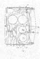
図1には、本実施形態では標準血液透析用に利用可能である、本発明の一実施形態に基づくカセット10が示されている。図1では、カセット10の表面がハッチングされた領域B(2つの部分面)と、ハッチングされていない領域Aとに区分されている。カセット10の表面と、付属の機械ブロック(図7参照)の表面は、互いに重なり合うこれらの面領域AおよびBにいずれも区分されており、面領域A(図1で影が付いていない部分)には、基本バリエーションとして、本図に示す標準血液透析用のカセットも含めたあらゆるカセットに共通した、接続されるべきアクチュエータまたはセンサのコンポーネントが格納されており、平面Bは、例えば図2に示すカセットの場合のように必要な場合にだけ利用される、オプションとして使用されるべきアクチュエータまたはセンサが機械ブロック(図7参照)に設けられる領域を提供している。 FIG. 1 shows a
このカセットは、本図に示す実施例ではポリプロピレンでできたカセット本体12で構成されている。カセット本体の上に、例えばポリオレフィンエラストマ混合物でできた、ここには詳しくは図示しないカバーシートが装着されている。このカバーシート14によって、後で詳しく説明する通路や凹部が覆われる。ダイアライザへ通じる動脈配管18にある動脈注入隔壁16と、ダイアライザへ通じる静脈配管22にある静脈注入隔壁20とが設けられている。ダイアライザ自体と相応のホース接続部は、本図に示す実施例では詳しくは図示されていない。符号24は患者からの血液入口であり、符号26は患者への血液出口である。この場合にも、同じくポリオレフィンエラストマ混合物でできているそれぞれのホースは、図面を簡略にする理由から図示されていない。カセット本体12には通路28が切り欠かれている。これらの通路は一連のバルブ30による作用を受ける。 This cassette is composed of a cassette body 12 made of polypropylene in the embodiment shown in the figure. A cover sheet, not shown in detail, is mounted on the cassette body, for example made of a polyolefin elastomer mixture. The cover sheet 14 covers a passage and a recess that will be described in detail later. An
これらのバルブの構造は、例えば出願人のドイツ特許出願第10046651号明細書から明らかであり、この点に関しては同明細書を援用する。基本的にこれらのバルブ30は圧力通路とシールキャップとを備える弁体を有しており、このシールキャップは、圧力通路の弁体側の端部を周囲に対して閉止するように弁体と協働し、圧力通路とシールキャップの間には圧力空間を生成可能なので、シールキャップは流体通路へ侵入するための変形可能なシール領域を有することになり、それによって場合により流体通路を閉止する。 The structure of these valves is apparent, for example, from the Applicant's German Patent Application No. 10046651, which is hereby incorporated by reference. Basically, these
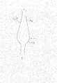
カセット本体12には、さらに動脈測定室32と静脈測定室34が収容されている。これらの測定室の原理的構造は、例えば液体すなわち血液の流動方向が矢印で示されている図11を見れば明らかである。測定室32および34は、センサ36を収容できるようにするために通路拡張部を有している。測定室32、34の輪郭は、図11に示すように、ディフューザノズルの幾何学形状に対応している。液体の流入領域の領域に、ノズル40となって終わるディフューザ38が配置されている。このときディフューザ38の断面積拡張部は、ノズル40の断面積狭隘部に比べて比較的通過しやすい。動脈または静脈の測定室32、34の領域には、多機能センサの形態で構成されたセンサ36が配置されている。このような多機能センサの構造は、出願人のドイツ特許出願公開第19837667号明細書に詳細に説明されており、その説明の全内容を援用する。 The cassette body 12 further accommodates an
カセットには、相応の通路によって動脈血を通す通路とそれぞれファントムバルブ46を介して接続された、動脈ポート42とヘパリンポート44とが設けられている。ファントムバルブ46は、本発明のカセット10では、従来式の開いたT型分岐の代わりに用いられている。このようなファントムバルブでは、主血液流から見たときの通路壁に切れ目がない。このようなファントムバルブの詳細な構造は本件出願人のドイツ特許出願第10053441号明細書から明らかであり、ここでも同明細書を援用する。符号48は、同じくファントムバルブ46を介して、血液を通す通路28へと合流する静脈ポートであり、すなわち本例では血液を通す通路の静脈部分に合流する静脈ポートである。 The cassette is provided with an arterial port 42 and a heparin port 44 which are connected to each other through a
符号50は、血液を送り出す役目をする2つのポンプ室である。ポンプ室50の構造は図12に詳細に図示されている。機械側に設けられたダイヤフラムポンプを介して作動するポンプ室50は、図1からすでに明らかなように、室全体を均等に貫流させるために実質的に接線上にある供給部と排出部を備えている。ポンプ室50の形態は、相応に成形されたカセット本体12によって規定され、近似的に部分球形となっている。前記接線は、部分球形の円形断面の接線であり、図1でポンプ室50を示す円形の接線である。前記供給部は、血液が通路28からポンプ室に入る入口であり、また、前記排出部は、血液がポンプ室50から通路28に出る出口である。このカセット本体の上面には、ポンプ室50の回りを取り囲むように、圧搾隆起部としての役目をする高くなった縁部52が突出されている。これに加えて、図12から明らかなように、圧送段階のときに、すなわちカバーシート14の一部がポンプ室50中に突出されてポンプ室の内面と前記カバーシートとの間に洗浄通路54を形成する。この洗浄通路は、前記縁部52が前記カバーシートのポンプ室の周りの部分と当接して封止される。この洗浄縁部、即ち洗浄通路54は、図12には図示しない機械側のダイヤフラムポンプのポンプ球冠部が、カセット側のポンプ室の半径よりも小さい半径を有していることによって構成されるのが好ましい。この半径差Δrが図12に図示されている。それによって洗浄通路54が形成される。この洗浄通路54は、圧送の極位置のときに送り出される血液のための環状スペースである。この環状スペースは、一方では、圧送段階の最後にシート表面と射出成形表面の間に挟み込まれることによる血液の損傷を防ぐと共に、他方では、環状スペースが設けられていなければ始動段階の開始時に生じることになる速い流動速度とせん断応力による血液の損傷も防止する。
カセットの上側領域が取付状態にあるとき、図10の断面図に再度図示されている換気室56が形成される。この換気室には換気膜58が配置されており、この換気膜によって、相応に集められた空気を分離することができる。この換気膜は、特に疎水性または疎油性の性質を有する半透性膜として構成されているからである。換気膜としては、膨張させた、または焼結されたポリテトラフルオロエチレンを用いるのが好ましい。換気膜58の上側には換気接続管60が配置されており、この換気接続管と、ここには詳しくは図示しない液体取扱機械との連動については後で説明する。換気室56では血液流の減速によって気泡が捕集される。図10に示すように、カセットの最低限の所要面積で効率的な空気分離をするために回転流が生成される。このとき最終的な回転流の生成は、液体取扱機械100でカセット10が動作状態になったとき初めて行われる(図10参照)。図10では真空吸引通路102だけしか図示されていない相応の真空接続システムにより、カセット10のカバーシート14が液体取扱機械の中に引き込まれる。それによって換気室56のほぼ円形の断面が形成される。換気室56に合流する通路もカバーシート14と共に機械側へ若干入り込み、その結果、室内でほぼ接線上での流入が実現されることによって、血液の回転流がサポートされる。換気接続管60のところでは、機械側で能動的な吸引を行うことができる。全体的にみてこの換気室56には設計上わずかな充填容積しか生じない。 When the upper region of the cassette is in the mounted state, a
図13を参照すると、通路28の原理的な構造について説明することができる。原則として通路28の通路構成にあたっては、平滑なシート表面と平滑な通路面が製作されるように留意する。段差、デッドスペース、乱流、衝突面などは避ける。わずかな方向および速度の変化が生じるように配慮する。流れの筋が分かれるのをほぼ防止する。全ての通路28および室50は、通路に随伴するように、カバーシート14のほうを向いた縁部隆起52(図12も参照)を有している。カセット10を液体取扱機械に挿入するとシート14が縁部隆起52に押し付けられ、その結果、全ての通路28が周囲に対して密閉される。カセットの裏側、すなわち通路壁の外側には通路に随伴するウェブ62が形成されており、このウェブを介して裏側の押圧力が縁部隆起52へと伝えられ、そのようにして均等で線状の力分布を実現する。 Referring to FIG. 13, the principle structure of the
図13を参照すると、カセット本体12が外側縁部64のところでカバーシート14と溶着されている様子も説明することができる。 Referring to FIG. 13, it can be described how the cassette body 12 is welded to the cover sheet 14 at the
カセット10は、位置決め補助具として、挿入時に機械側のセンタリングピンを収容する切り欠かれたセンタリング溝66を有している。さらに、挿入時に対応する機械面に当るストッパラグ68が一体成形されている。それによりカセット10が高さと角度に関して案内される。カセット10を液体取扱機械100に圧着すると、ここには詳しくは図示しないスナップ部材で液体取扱機械との係止が行われるので、カセット10はアライメントされた状態で固定される。取扱を容易にするために、カセットはセンタリング溝66と向かい合う側に一体成形された取っ手70を有している。 The
動脈注入隔壁16または静脈注入隔壁20は、ここに示した実施例では従来式の注入部位とは異なり、その本体がカセット本体12自体によって形成されるように構成されており、それにより、ここでは弾性的な隔壁だけがスナップリング(ここには図示せず)によって固定されている。隔壁は、本図に示す実施例ではエラストマでできている。 The
図4は、図1のカセットから改変した実施形態を示している。図4に示すこのカセット10も標準血液透析に用いられるものであり、図1のカセット10と大筋で同じ構造を示している。特に、すでに説明したカセット10の構成要素については詳細な説明を割愛する。ただし、図1の実施形態における取っ手70に代えてダイアライザ72がカセット10の横に統合されており、ここではダイアライザに通じる配管18および22がダイアライザに直接合流している。従来式に構成されていてよいダイアライザでは、透析液接続部に符号74および76が付されている。 FIG. 4 shows an embodiment modified from the cassette of FIG. This
図2には、オンライン血液透析濾過カセットとして施工されたカセット10が示されている。さまざまな部材の配置から明らかなように、カセット本体12は、すでに図1の標準血液透析用の実施例を参照して説明したカセット本体を前提としている。この実施例から既知となっている部材は全て、オンライン血液透析濾過用の図2の実施形態にも同様に見出すことができる。その意味で再度追加して説明は行わない。ただし、血液透析濾過カセットとしての動作のために必要な部材については説明する。そのような部材には置換液コネクタ80が含まれており、この置換液コネクタを介して置換液が通路28に供給される。通路には置換液通路バルブ82が設けられており、このバルブを介して通路28を相応の部位で閉止可能である。これらの通路を通じて、置換液ポンプ室を形成する2つの平行なポンプ室84へと置換液が案内される。置換液ポンプ室84は、先ほどすでに具体的に説明した血液用のポンプ室に実質的に相当している。置換液は通路28を起点として、カセット本体12の対向する側に位置する置換液トンネル86によって案内される。この置換液トンネルは裏側で適当に閉じられており、例えば溶着されたシートで閉じられている。置換液は、前希釈ポート88を介して、または後希釈ポート90を介して、血液を通す通路28に導入することができる。これらのポートは、ここでもやはりファントムバルブとして構成されており、ここでもドイツ特許出願第10053441号明細書に記載された設計上の構成を援用する。 FIG. 2 shows a
実質的に置換液ポンプ室84で形成される置換液領域は置換液溶接縁部92で取り囲まれており、カバーシート14がこの置換液溶接縁部と封止をするように溶着されているので、この置換液を処理するカセット10の領域は血液を通す領域から切り離されている。 The replacement liquid region substantially formed by the replacement
図5には、図2の実施形態の変形例が示されている。図4の実施形態と同じく、ここでもやはりダイアライザ72がカセット10に直接統合されている。 FIG. 5 shows a modification of the embodiment of FIG. As with the embodiment of FIG. 4, the
図3には、カセットのさらに別の一体型の実施形態として、急性治療用のカセット10が図示されている。このカセットは、血液取扱部分の領域では図1の実施形態と同一の構造となっている。置換部分に関しては図2の実施形態に部分的に相当しているが、ここでは置換液コネクタ80と通路28を介して引き込まれた置換液が供給される1つの置換液ポンプ室84しか設けられていない。置換ポンプ室84の前後に、ここでも図2の実施形態と同様に置換液通路バルブ82が設けられている。急性治療用の本実施形態で符号94が付されている別のポンプ室は、通路28を介して濾液出口96と連通すると共に、ここには詳しくは図示しないダイアライザと連通する濾液接続部98に合流している。 FIG. 3 shows a
図6にも、やはり図3のカセット10の改変された実施形態が示されている。ここでも取っ手の代わりに同じくダイアライザ72が統合されているが、ここでは、濾液ポンプ94へと通じる、ダイアライザ72と濾液を通す通路28との間の接続部99が設けられている。 FIG. 6 also shows a modified embodiment of the
図7には、カセット10が挿入されていない液体取扱装置100の実施形態が示されている。この液体取扱装置100は前述したいずれのカセットでも挿入可能なように構成されており、相応のプログラム交換によって、例えば図1の実施形態に示すカセットを挿入した場合には、基本体外血液回路すなわち標準透析が外部ダイアライザを用いて実施される。図2に示す実施例のカセット10を挿入すると、例えばオンライン血液透析濾過またはオンライン血液濾過のバリエーションが、そのために必要な、場合により基本装置の流体回路への自動式の接続部(図示せず)を備えるコンポーネントの利用によって具体化される。カセットの側で図4と図5に示す実施形態で示したように、ダイアライザとのダイアライザ接続部が一体化されて高度に統合された変形例も可能である。急性透析治療は、図3に示す実施例のカセット10を挿入した場合に可能である。 FIG. 7 shows an embodiment of the
この液体取扱機械100は、最重要なコンポーネントを包囲、包含、または収容するフレーム104で実質的に構成されている。フレーム104には一方に扉106が取り付けられており、また他方では機械ブロック108がフレームで案内されている。フレーム104により、扉106と装置内部すなわち扉のヒンジ、扉のロック部、押圧アクチュエータ、裏壁との間で発生する全ての力が受け止められる。さらにフレームは扉のロック部110を含んでいる。扉106と機械ブロック108の間に、図8と図9に示すようにカセット10が収容され、押圧によって密閉される。機械のカセット領域には、カセットが液体取扱機械で正しく位置決めされているかどうかを判定するセンサ部材が含まれている。このセンサ装置または他のセンサ装置は、カセットの型式を認識するのに適しているように設計されていてよい(例えばカセットのバーコードにより)。 The
機械ブロック108には、体外血液回路を制御および管理するための主要な部材、例えばポンプ、バルブ、センサなどが含まれている。この機械ブロック108は、カセット10に対するもっとも重要なインターフェースを成立させるものである。このときカセット表面が装置に連結され、それにより、カセット10の密閉およびこれに伴う流動経路の設定が行われる。機械ブロックはフレームの中で可動に案内されており、すでに先ほど説明したように扉が閉じられるまでカセット10を固定する。 The machine block 108 includes the main components for controlling and managing the extracorporeal blood circuit, such as pumps, valves, sensors, and the like. This machine block 108 establishes the most important interface to the
液体取扱機械には、図7、図8、図9には具体的には図示していない油圧ピストンポンプが含まれている。これは一方では血液ポンプまたはオプションの置換液補充ポンプまたは限外濾過ポンプである。これらのポンプはポンプ室C、Dすなわち血液ポンプ室と油圧接続されており、または、ポンプ室E、Fすなわちオプションの濾液ポンプ室および/またはオプションの置換液ポンプ室と油圧接続されている。さらに液体取扱機械100には、必要な空気圧(過圧または真空)を生成するために、ここには詳しくは図示しないコンプレッサが含まれている。さらに液体取扱機械100は、詳しくは図示しないやり方で、圧力変動を補償するための空気圧装置緩衝容器、メイン電子装置ボックス、ヘパリン注入ポンプ、および血圧モニタモジュールを有している。 The liquid handling machine includes a hydraulic piston pump not specifically shown in FIGS. This is on the one hand a blood pump or an optional replacement fluid replenishment pump or an ultrafiltration pump. These pumps are hydraulically connected to pump chambers C, D or blood pump chambers, or hydraulically connected to pump chambers E, F, optional filtrate pump chamber and / or optional replacement fluid pump chamber. Furthermore, the
ここには同じく詳しくは図示していない押圧アクチュエータが、フレーム104の裏壁にあることを強調しておく。ここには空気で膨らませることができるエアクッションが組み込まれており、このエアクッションが、フレーム104に可動に支持された機械ブロック108全体を閉じた扉106に向かって動かし、押圧することができる。 It is emphasized here that there is also a pressing actuator, not shown in detail, on the back wall of the frame 104. Here, an air cushion that can be inflated with air is incorporated, and this air cushion can move and press the entire mechanical block 108 movably supported by the frame 104 toward the closed door 106. .
さらに、空気を通す個別のホースに代えて空気分配プレートが機械ブロック108に設けられており、この空気分配プレートは空気圧装置へのメイン接続部を含むと共に、そこに組み込まれた通路を介して、固有のホース配管を使わずに圧縮空気や真空をバルブやアクチュエータへと送ると同時に、機械ブロックを液体取扱機械100の内部に対して閉ざしている。 In addition, an air distribution plate is provided in the machine block 108 instead of a separate hose for passing air, which includes a main connection to the pneumatic device and via a passage incorporated therein. The machine block is closed with respect to the inside of the
オンライン血液透析濾過を実施するために、液体取扱機械100にオプションのモジュールが設けられていてよい。例えばこの場合、カセット10を透析液回路へ自動的に接続するためのオンライン補充ポートや、洗浄液をフィードバックするためのオンライン洗浄ポートが含まれていてよい。 An optional module may be provided in the
カセット10を挿入するためには扉106を開かなくてはならない。カセット10を挿入し、センタリング溝を位置決めした後、カセットにあるスナップフックを用いて機械ブロックの表面で固定する。 In order to insert the
カセットのほうを向いている機械ブロックの側は、ここには詳しくは図示しない柔らかいエラストママットで被覆されており、押圧が完了した後にこのエラストママットがカセット10を密閉する。このエラストママットの詳しい説明は、出願人のドイツ特許出願第10157924号明細書ですでに行われているので、ここでは同明細書の全内容を援用する。 The side of the machine block facing the cassette is covered here with a soft elastomer mat, not shown in detail, which seals the
扉を閉めてロックした後、前述したエアクッションを空気で膨らませることによって押圧が行われる。開いてカセットを取り出すときは、扉を開ける前にエアクッションの空気を抜くことによって押圧を再び解消する。 After closing and locking the door, pressing is performed by inflating the air cushion described above with air. When opening and taking out the cassette, the pressure is released again by bleeding the air cushion before opening the door.
十分な押圧を実現し、不均等な力の導入によって機械ブロックが傾くのを防ぐために、エアクッションはほぼ機械ブロックまたはカセット10の大きさを有している。 The air cushion is approximately the size of the machine block or
ただし、エアクッションと機械ブロックの間には別のコンポーネント、例えば制御バルブまたは制御バルブを備える空気分配プレートがあるので、スペーサボルトによって力の伝達が行われる。 However, since there is another component between the air cushion and the machine block, such as a control valve or an air distribution plate with a control valve, the force is transmitted by spacer bolts.
扉106、フレーム104、および裏壁の間の摩擦接合は、扉のヒンジと、ロック部110と、ここには詳しくは図示しないフレームと裏壁の間の連結ボルトとによって行われる。 Friction joining between the door 106, the frame 104, and the back wall is performed by a door hinge, a lock 110, and a connecting bolt between the frame and the back wall, which is not shown in detail here.
すでに触れたように、申し分のない動作のためにはカセット10が常に押圧されていなくてはならない。そのためには、取扱中に扉がロックされていることが必要である。このロックは、右上と右下の扉領域にある2つのロックボルト(ここには詳しくは図示せず)によって行われ、これらのロックボルトは、自動的に行われる操作時に、扉106の内部の2つの対応する穴の中へ入る。この出し入れは空気圧で行われる。扉の中に入っているボルトと、扉への圧力付勢によって生じる横方向力とによって、空気圧装置が故障したときに扉が誤って開いてしまう恐れはない。ロックが行われているかどうかを点検するために、ボルトの動きを検知するホール間隔センサが組み込まれていてよい。これに加えてこの信号が、別個のセンサによって記録可能な扉の位置に関する情報とさらに組み合されていてもよい。これに加えて、ここには詳しくは図示しないロックボルトがさらに係止部を有していてもよい。この係止部は、ロックボルトの対応する湾曲部に係止されて扉を相応の位置で保持することができる、ばねで付勢される扉側の係止球で構成される。係止を簡単にするために導入用の面取りが設けられている。係止位置から扉を開くには、そこに存在している係止球を機械装置によって引き戻す。 As already mentioned, the
液体取扱機械100の側では、血液回路は、高精度の送液ポンプまたは容積式の調量ユニットとして利用することができる、2つの独立したポンプ室CおよびDを備えて油圧制御される少なくとも1つのダイヤフラムポンプと、一連のバルブM、Oと、流動経路を制御するための室Nと、監視および制御に必要な高度に集積化されたセンサ装置G、Hと、能動的な空気除去部すなわちカセット換気部Aが接続された空気分離室Iと、血液回路(空気のない回路)と、カセットを固定するための扉106とで実質的に構成されている。 On the
液体取扱機械100は、過圧のための空気圧システムと負圧のための空気圧システムをそれぞれ含んでいる。負圧は、例えばカセット10のシート14と装置側との間に負圧を印加して、シートが可塑変形したときに通路が狭まるのを防ぎ、補充部位のところでシートを持ち上げることによってアクセスが開かれた状態に保ち、ポンプ装置での空気コンプライアンスを防止し、特別なセンサ位置でセンサとシートの間に空気のない結合を保証するのに役立つ。空気の吸出しを惹起するのは、装置側で開口部およびこれに接続された吸出しユニットすなわち真空ポンプであり、真空分布は全面積にわたってできるだけ均等かつ確実に保証されているのが望ましい。休止状態のときは、良好な洗浄を可能にするために、開口部が少なくともほぼ閉じられるのがよい。しかし作動時には支障のない空気吸出しが可能であるべきである。この問題は、ドイツ特許出願第10157924号明細書に記載された、すでに先ほど述べたエラストママットによって解決される。 The
カセット10では、縁部領域および安全性のための少数の溶着部を除き、いかなる通路密閉部も含まれていない。従って、全ての流動経路および通路の密閉は押圧によって行われる。そのためにカセットは、すでに先ほど説明した、機械ブロック108と扉106の間で使い捨て部品が押圧されたときに弾性マットに押し込まれることによって密閉可能なシール隆起部52を、通路縁部のところに有している。
ここには詳しくは図示しない空気分配プレートは機械ブロック108の裏面にあり、例えば空気圧システムの2つのダイヤフラムポンプと接続されており、すなわち過圧ポンプおよび負圧ポンプと接続されている。空気分配プレートは機械ブロック裏面に対してシールマットで密閉されており、一体化された通路構造部を介して圧縮空気や真空の引き込みを可能にするので、各々のバルブに独自のホース配管を必要としない。空気分配プレートの上には複数の回路があり、すなわち真空回路と、常に圧縮空気を必要とするコンポーネントへの供給をするためにコンプレッサと直結された圧縮空気回路と、特定の状態でしか圧縮空気を供給しなくてよい敏感なコンポーネントを保護するための、切換弁によってコンプレッサから分離可能な圧縮空気回路と、空気排出回路とがある。 The air distribution plate, not shown in detail here, is on the back of the machine block 108 and is connected to, for example, two diaphragm pumps of a pneumatic system, i.e. connected to an overpressure pump and a negative pressure pump. The air distribution plate is sealed against the back of the machine block with a seal mat, allowing compressed air and vacuum to be drawn in through an integrated passage structure, so each valve requires its own hose piping And not. There are several circuits above the air distribution plate: a vacuum circuit, a compressed air circuit directly connected to the compressor to supply components that always require compressed air, and compressed air only in certain conditions. There is a compressed air circuit that can be separated from the compressor by a switching valve and an air exhaust circuit to protect sensitive components that may not need to be supplied.
空気分配プレートに多数の制御弁を統合することによって、電力供給部も小型の制御配線板を通じてまとめることが可能であってよい。いくつかのバルブは特定のオプションでしか必要ないので、モジュール形式での後付け可能性が保証されていなくてはならない。 By integrating a number of control valves into the air distribution plate, it may be possible to bundle the power supply through a small control wiring board. Since some valves are only required with certain options, the possibility of retrofitting in a modular format must be guaranteed.
センサ装置とポンプ接続部は、貫通部や切欠きを通してプレートに挿通される。 The sensor device and the pump connection part are inserted into the plate through the through part or the notch.
体外血液回路の監視と制御をするために、この液体取扱機械100には集積化されてセンサモジュールにまとめられたセンサが必要である。それぞれ2つのモジュールがペアとして協働する。このとき一方のモジュールは扉106に格納されており、対応するモジュールは機械ブロック108に格納されている。動脈分岐が動脈測定室Gによって測定され、静脈分岐が静脈測定室Hによって測定される。集積化された測定センサ装置については、同じ出願人のドイツ特許出願公開第19837667号明細書およびドイツ特許出願第10143137号明細書に記載されている。これらのセンサは協働して特に次のような特性を有しており、または次のような可能性を提供する。 In order to monitor and control the extracorporeal blood circuit, the
− 血液容積の測定と管理
− ヘマトクリットの測定
− 熱エネルギーバランスの測定と管理
− 体温の測定と管理
− (循環が行われる)フィステルの状態の測定
− 空気の検知
− フィステル圧の測定
マルチセンサモジュールは、容積管理、ヘマトクリットの測定、および空気検知のための超音波センサと、自動的なアクセス分析、体温管理、および熱エネルギーバランスのための温度センサと、圧力監視のための圧力センサと、自動的な血液認識のための光学センサとを装備しているのが普通である。-Measurement and management of blood volume-Measurement of hematocrit-Measurement and management of thermal energy balance-Measurement and management of body temperature-Measurement of fistula state (where circulation is performed)-Detection of air-Measurement of fistula pressure Ultrasonic sensors for volume control, hematocrit measurement, and air detection, temperature sensors for automatic access analysis, body temperature management, and thermal energy balance, pressure sensors for pressure monitoring, automatic Usually equipped with an optical sensor for blood recognition.
バルブMおよびポンプバルブOに関して、その構造については同じくドイツ特許出願公開第10046651号を援用する。 Regarding the structure of the valve M and the pump valve O, German Patent Application No. 10046651 is also used for the structure.
図7に図示されている上に挙げたバルブのほか、追加として、この図7には詳しくは図示されていないいわゆるファントムバルブも設けられている。ファントムバルブの構造と機能形態に関しては、ドイツ特許出願公開第10053441号明細書を援用する。 In addition to the valves listed above in FIG. 7, there are additionally so-called phantom valves not shown in detail in FIG. As for the structure and functional form of the phantom valve, German Patent Application No. 10053441 is incorporated.
符号Nは、体外血液回路のアラーム中に安全な状態を確立するために役立つ安全クランプを表しており、この安全クランプは患者配管すなわち患者から出ていく血液流と患者に入っていく血液流を全て遮断する。好ましくないコンプライアンス効果を回避するために、および、このシステムは流動を逆転させるように設計されているので、この安全機能は動脈側でも静脈側でも保証されていなければならず、そのため、機械的に連結されていてよい2つの遮断クランプNが利用される。 The symbol N represents a safety clamp that helps to establish a safe condition during an alarm in the extracorporeal blood circuit, and this safety clamp is used to connect the blood flow to and from the patient tubing or patient. Block everything. In order to avoid undesirable compliance effects and because the system is designed to reverse the flow, this safety function must be ensured on both the arterial and venous sides, so mechanically Two shutoff clamps N, which can be connected, are used.
遮断クランプは、あらゆる妨害的な影響を最低限に抑えて高い安全性要求に応えるために、できるだけ患者の近くで作用するのが望ましい。そこで、患者ホースに直接作用するホースクランプが利用される。 The blocking clamp should work as close to the patient as possible to minimize any disturbing effects and meet high safety requirements. Therefore, a hose clamp that directly acts on the patient hose is used.
ここで意図され、考えられる一実施形態は、空気圧で開いて再び閉じるクランプタペットを用いて、扉の内側にあるクランプ条片に対してホースをクランプすることにある。このような種類のシステムは受動的にばねで閉じるようになっており、すなわち圧力も電気も使わないので、故障の場合にも安全性の観点から好ましい。 One embodiment contemplated and contemplated herein is to clamp the hose against the clamp strip inside the door using a clamp tappet that is pneumatically opened and closed again. This type of system is passively closed by springs, ie, it uses neither pressure nor electricity, which is preferred from a safety point of view even in case of failure.
図8には、図7に準ずる液体取扱機械100が図2のカセット10を挿入された状態で示されている。それに対して図9には、図5の実施形態に準ずるカセット10を備える液体取扱機械100が示されており、この場合、カセットではダイアライザが液体取扱機械100との間に自動式の透析液接続部KおよびLを有している。 FIG. 8 shows a
以上に開示した新規の装置は、将来的な利用可能性やオプションも視野に入れたうえで、高いフレキシブルさと利用可能性を実現しながら、厳密なモジュール形式での利用法を追求するものである。統合された血液モジュールはあらゆる分野の血液取扱方法の実施を可能にし、すなわちオンライン血液透析濾過、オンライン血液濾過、および急性治療を可能にする。 The new device disclosed above pursues the usage in the strict modular form while realizing high flexibility and availability, considering future availability and options. . The integrated blood module allows the implementation of blood handling methods in all fields, ie online hemodiafiltration, online hemofiltration and acute therapy.
急性治療に関して指摘しておくと、急性治療すなわち急性透析または急性濾過のために用いられる機械は、相応に容易に搬送して複雑な供給構造(例えば水の接続部)なしで機能させるために、単純に構成されていなくてはならない。従ってこのシステムでは、事実上例外なく、あらかじめ完成した解決法で血液が処理される。図3または図6に示す実施形態を適用すれば、置換液が袋から供給され、図示したポンプで濾液がフィルタから空の袋へ取り除かれる急性血液濾過を実施することができる。この場合、袋の接続を除いてそれ以外の措置は何も必要ない。とはいえ、相応の手間をかけて追加的に透析も可能にすることも当然ながら可能であろう。さらに別案として、カセット内部の接続が相応に変更されていれば、置換液ポンプを透析液供給ポンプとして利用することもできるであろう。そうすれば、袋に充填された透析液を平衡をとりながらダイヤフラムポンプでフィルタに供給し、その間に濾液ポンプで液体を制御下で運び出すことができる。このような機械の場合でも、液体制御のためにそれ以外のコンポーネントは何も必要ない。 With regard to acute therapy, the machine used for acute therapy, i.e. acute dialysis or acute filtration, should be reasonably easily transported and function without complex supply structures (e.g. water connections). It must be simple. The system thus processes blood with a pre-completed solution with virtually no exception. If the embodiment shown in FIG. 3 or FIG. 6 is applied, acute blood filtration can be performed in which the replacement liquid is supplied from the bag and the filtrate is removed from the filter to the empty bag by the illustrated pump. In this case, no other measures are required except for the bag connection. Nevertheless, it will of course be possible to allow additional dialysis with considerable effort. As a further alternative, the replacement fluid pump could also be used as a dialysate supply pump if the connections inside the cassette are changed accordingly. If it does so, the dialysate with which the bag was filled will be supplied to a filter with a diaphragm pump, balancing, and in the meantime, a liquid can be carried out by control with a filtrate pump. Even with such machines, no other components are required for liquid control.
このような各々の種類の取扱を、ダブルニードルモードでもシングルニードルモードでも行うことができる。ダブルニードルモードまたはシングルニードルモードの説明に関しては、ドイツ特許第10042324号明細書を援用する。 Each kind of handling can be performed in either the double needle mode or the single needle mode. For the description of the double-needle mode or the single-needle mode, the
以上に説明した本発明には一連の新開発が含まれており、ポンプ室ならびにこれに付属する機械側のポンプ球冠部ばかりでなく、空気分離室の新規の構成も含まれている。このような血液取扱のための構成要素またはカセットまたは機械について、本発明の枠内においてはそれぞれ単独で、すなわちカセットや機械の他の要素と組み合わせることなく、権利保護を申請するものである。 The present invention described above includes a series of new developments and includes not only the pump chamber and the pump ball crown on the machine side attached thereto, but also a new configuration of the air separation chamber. For such blood handling components or cassettes or machines, within the framework of the present invention, the application for rights protection is made independently, i.e. without being combined with other components of the cassette or machine.
Claims (29)
Translated fromJapanese前記カセットの前記複数の室のうちの少なくとも1つの室は、前記上面に形成された上側縁部により囲まれたポンプ室であり、前記少なくとも1つのポンプ室は、前記上面から凹んだ部分球形の形態を有しており、圧送段階のときに、前記カバーシートの一部が前記少なくとも1つのポンプ室の中に突出されてポンプ室の内面と前記カバーシートとの間に洗浄通路を形成し、この洗浄通路は、前記上側縁部に突設された隆起部が前記カバーシートのポンプ室の周りの部分と当接して封止され、
前記少なくとも1つのポンプ室は、前記部分球形の断面の円形の接線方向に流体が前記通路からポンプ室に流入する入口と、前記接線方向に流体前記ポンプ室からが通路に流出する出口とを備えている、装置。A liquid handling machine, this insertion possible in liquid handling machinery, covering a plurality of chambers anda plurality ofcassette body passageandis formedin the uppersurface and these chambers and passagesin communication with the plurality of chambersIn a device for handling medical liquid, comprising a cassette havinga cover sheetprovided on the upper surface of the cassette body ,
At least one of theplurality of chambers of the cassetteis a pump chambersurrounded by an upper edge formed on the upper surface , and the at least one pump chamber hasa partially spherical shaperecessed from the upper surface . Thecover sheet is protruded into the at least one pump chamberto form a cleaning passage betweenthe inner surface of the pump chamber and the cover sheetduring the pumping stage, In this cleaning passage, a protruding portion protruding from the upper edge is in contact with a portion around the pump chamber of the cover sheet and sealed,
The at least one pump chamber includes an inlet through which fluid flows from the passage into the pump chamber in a circular tangential direction of the partial spherical cross section, and an outlet through which fluid flows from the pump chamber into the passage in the tangential direction. The device .
Applications Claiming Priority (2)
| Application Number | Priority Date | Filing Date | Title |
|---|---|---|---|
| DE10224750.1 | 2002-06-04 | ||
| DE10224750ADE10224750A1 (en) | 2002-06-04 | 2002-06-04 | Device for the treatment of a medical fluid |
Related Parent Applications (1)
| Application Number | Title | Priority Date | Filing Date |
|---|---|---|---|
| JP2004508863ADivisionJP4537198B2 (en) | 2002-06-04 | 2003-05-22 | Medical fluid handling equipment |
Publications (2)
| Publication Number | Publication Date |
|---|---|
| JP2010012329A JP2010012329A (en) | 2010-01-21 |
| JP5032548B2true JP5032548B2 (en) | 2012-09-26 |
Family
ID=29594250
Family Applications (3)
| Application Number | Title | Priority Date | Filing Date |
|---|---|---|---|
| JP2004508863AExpired - LifetimeJP4537198B2 (en) | 2002-06-04 | 2003-05-22 | Medical fluid handling equipment |
| JP2009242199AExpired - Fee RelatedJP5032548B2 (en) | 2002-06-04 | 2009-10-21 | Medical fluid handling equipment |
| JP2009242200AExpired - LifetimeJP5173981B2 (en) | 2002-06-04 | 2009-10-21 | Medical fluid handling equipment |
Family Applications Before (1)
| Application Number | Title | Priority Date | Filing Date |
|---|---|---|---|
| JP2004508863AExpired - LifetimeJP4537198B2 (en) | 2002-06-04 | 2003-05-22 | Medical fluid handling equipment |
Family Applications After (1)
| Application Number | Title | Priority Date | Filing Date |
|---|---|---|---|
| JP2009242200AExpired - LifetimeJP5173981B2 (en) | 2002-06-04 | 2009-10-21 | Medical fluid handling equipment |
Country Status (8)
| Country | Link |
|---|---|
| US (11) | US7648627B2 (en) |
| EP (3) | EP2295090B1 (en) |
| JP (3) | JP4537198B2 (en) |
| CN (3) | CN101676002B (en) |
| AU (1) | AU2003240694A1 (en) |
| DE (1) | DE10224750A1 (en) |
| ES (2) | ES2529095T3 (en) |
| WO (1) | WO2003101510A1 (en) |
Families Citing this family (254)
| Publication number | Priority date | Publication date | Assignee | Title |
|---|---|---|---|---|
| US6852090B2 (en) | 1997-02-14 | 2005-02-08 | Nxstage Medical, Inc. | Fluid processing systems and methods using extracorporeal fluid flow panels oriented within a cartridge |
| US6877713B1 (en) | 1999-07-20 | 2005-04-12 | Deka Products Limited Partnership | Tube occluder and method for occluding collapsible tubes |
| US7780619B2 (en) | 1999-11-29 | 2010-08-24 | Nxstage Medical, Inc. | Blood treatment apparatus |
| US6497676B1 (en) | 2000-02-10 | 2002-12-24 | Baxter International | Method and apparatus for monitoring and controlling peritoneal dialysis therapy |
| US20050010158A1 (en)* | 2001-05-24 | 2005-01-13 | Brugger James M. | Drop-in blood treatment cartridge with filter |
| US7241272B2 (en) | 2001-11-13 | 2007-07-10 | Baxter International Inc. | Method and composition for removing uremic toxins in dialysis processes |
| WO2003086509A1 (en) | 2002-04-11 | 2003-10-23 | Deka Products Limited Partnership | System and method for delivering a target volume of fluid |
| US7175606B2 (en) | 2002-05-24 | 2007-02-13 | Baxter International Inc. | Disposable medical fluid unit having rigid frame |
| US7153286B2 (en) | 2002-05-24 | 2006-12-26 | Baxter International Inc. | Automated dialysis system |
| DE10224750A1 (en) | 2002-06-04 | 2003-12-24 | Fresenius Medical Care De Gmbh | Device for the treatment of a medical fluid |
| US7238164B2 (en)† | 2002-07-19 | 2007-07-03 | Baxter International Inc. | Systems, methods and apparatuses for pumping cassette-based therapies |
| DE60336724D1 (en) | 2002-07-19 | 2011-05-26 | Baxter Healthcare Sa | SYSTEM FOR PERITONEAL DIALYSIS |
| EP1539271B1 (en) | 2002-09-11 | 2014-04-16 | Fresenius Medical Care Deutschland GmbH | Blood treatment device for returning blood |
| US8235931B2 (en) | 2003-01-15 | 2012-08-07 | Nxstage Medical, Inc. | Waste balancing for extracorporeal blood treatment systems |
| US7686778B2 (en)* | 2003-01-15 | 2010-03-30 | Nxstage Medical, Inc. | Waste balancing for extracorporeal blood treatment systems |
| EP1680155B2 (en) | 2003-10-28 | 2015-11-04 | Baxter International Inc. | Dialysis machine with improved integrity test |
| US7632078B2 (en) | 2003-10-30 | 2009-12-15 | Deka Products Limited Partnership | Pump cassette bank |
| US8803044B2 (en) | 2003-11-05 | 2014-08-12 | Baxter International Inc. | Dialysis fluid heating systems |
| US8029454B2 (en) | 2003-11-05 | 2011-10-04 | Baxter International Inc. | High convection home hemodialysis/hemofiltration and sorbent system |
| US8038639B2 (en)* | 2004-11-04 | 2011-10-18 | Baxter International Inc. | Medical fluid system with flexible sheeting disposable unit |
| US7744553B2 (en) | 2003-12-16 | 2010-06-29 | Baxter International Inc. | Medical fluid therapy flow control systems and methods |
| US7476209B2 (en)* | 2004-12-21 | 2009-01-13 | Therakos, Inc. | Method and apparatus for collecting a blood component and performing a photopheresis treatment |
| US7935074B2 (en) | 2005-02-28 | 2011-05-03 | Fresenius Medical Care Holdings, Inc. | Cassette system for peritoneal dialysis machine |
| US20060195064A1 (en)* | 2005-02-28 | 2006-08-31 | Fresenius Medical Care Holdings, Inc. | Portable apparatus for peritoneal dialysis therapy |
| EP1883433B1 (en)* | 2005-05-06 | 2014-03-26 | Quanta Fluid Solutions Ltd | Dialysis machine |
| US20100089807A1 (en) | 2006-05-08 | 2010-04-15 | Keith James Heyes | Dialysis machine |
| ES2398526T3 (en)* | 2005-06-03 | 2013-03-19 | Fresenius Medical Care Deutschland Gmbh | System for monitoring the pressure in a bloodstream and device for use with such a system |
| US8197231B2 (en) | 2005-07-13 | 2012-06-12 | Purity Solutions Llc | Diaphragm pump and related methods |
| US7871391B2 (en)* | 2005-10-21 | 2011-01-18 | Fresenius Medical Care Holdings, Inc. | Extracorporeal fluid circuit |
| US20070248477A1 (en) | 2006-03-29 | 2007-10-25 | Alcon, Inc. | Cassette having elastomeric clamping ribs |
| US8366316B2 (en) | 2006-04-14 | 2013-02-05 | Deka Products Limited Partnership | Sensor apparatus systems, devices and methods |
| US10537671B2 (en) | 2006-04-14 | 2020-01-21 | Deka Products Limited Partnership | Automated control mechanisms in a hemodialysis apparatus |
| US7794141B2 (en) | 2006-04-14 | 2010-09-14 | Deka Products Limited Partnership | Thermal and coductivity sensing systems, devices and methods |
| US20140199193A1 (en) | 2007-02-27 | 2014-07-17 | Deka Products Limited Partnership | Blood treatment systems and methods |
| US8273049B2 (en)* | 2007-02-27 | 2012-09-25 | Deka Products Limited Partnership | Pumping cassette |
| US9717834B2 (en) | 2011-05-24 | 2017-08-01 | Deka Products Limited Partnership | Blood treatment systems and methods |
| US8926550B2 (en)* | 2006-08-31 | 2015-01-06 | Fresenius Medical Care Holdings, Inc. | Data communication system for peritoneal dialysis machine |
| US8870811B2 (en) | 2006-08-31 | 2014-10-28 | Fresenius Medical Care Holdings, Inc. | Peritoneal dialysis systems and related methods |
| IL186314A (en) | 2006-09-26 | 2011-09-27 | Alcon Inc | Valve that is normally closed in the free state |
| PL2091592T3 (en)* | 2006-10-30 | 2014-09-30 | Gambro Lundia Ab | An extracorporeal blood chamber |
| ES2401073T3 (en)* | 2006-10-30 | 2013-04-16 | Gambro Lundia Ab | Air separator for extracorporeal fluid treatment sets |
| WO2008053259A1 (en) | 2006-10-30 | 2008-05-08 | Gambro Lundia Ab | Hemo(dia)filtration apparatus |
| US9028691B2 (en) | 2007-02-27 | 2015-05-12 | Deka Products Limited Partnership | Blood circuit assembly for a hemodialysis system |
| US20090107335A1 (en) | 2007-02-27 | 2009-04-30 | Deka Products Limited Partnership | Air trap for a medical infusion device |
| KR102444304B1 (en) | 2007-02-27 | 2022-09-19 | 데카 프로덕츠 리미티드 파트너쉽 | hemodialysis system |
| US8491184B2 (en) | 2007-02-27 | 2013-07-23 | Deka Products Limited Partnership | Sensor apparatus systems, devices and methods |
| US8357298B2 (en) | 2007-02-27 | 2013-01-22 | Deka Products Limited Partnership | Hemodialysis systems and methods |
| US10463774B2 (en) | 2007-02-27 | 2019-11-05 | Deka Products Limited Partnership | Control systems and methods for blood or fluid handling medical devices |
| US8042563B2 (en) | 2007-02-27 | 2011-10-25 | Deka Products Limited Partnership | Cassette system integrated apparatus |
| US8409441B2 (en) | 2007-02-27 | 2013-04-02 | Deka Products Limited Partnership | Blood treatment systems and methods |
| US8562834B2 (en)* | 2007-02-27 | 2013-10-22 | Deka Products Limited Partnership | Modular assembly for a portable hemodialysis system |
| US8393690B2 (en)* | 2007-02-27 | 2013-03-12 | Deka Products Limited Partnership | Enclosure for a portable hemodialysis system |
| US8425471B2 (en) | 2007-02-27 | 2013-04-23 | Deka Products Limited Partnership | Reagent supply for a hemodialysis system |
| GB0708758D0 (en)* | 2007-05-04 | 2007-06-13 | Powderject Res Ltd | Particle cassettes and process thereof |
| WO2008150776A2 (en) | 2007-05-29 | 2008-12-11 | Fresenius Medical Care Holdings, Inc. | Solutions, dialysates, and related methods |
| US8057423B2 (en) | 2007-07-05 | 2011-11-15 | Baxter International Inc. | Dialysis system having disposable cassette |
| DE102007031722B4 (en)* | 2007-07-06 | 2011-06-16 | Carl Zeiss Surgical Gmbh | Device for reducing pressure fluctuations in an aspiration branch and surgical system |
| DE102007042964A1 (en)* | 2007-09-10 | 2009-03-19 | Fresenius Medical Care Deutschland Gmbh | Apparatus and method for treating a medical fluid and medical cassette |
| US9358331B2 (en) | 2007-09-13 | 2016-06-07 | Fresenius Medical Care Holdings, Inc. | Portable dialysis machine with improved reservoir heating system |
| US8597505B2 (en) | 2007-09-13 | 2013-12-03 | Fresenius Medical Care Holdings, Inc. | Portable dialysis machine |
| US9308307B2 (en) | 2007-09-13 | 2016-04-12 | Fresenius Medical Care Holdings, Inc. | Manifold diaphragms |
| US8240636B2 (en) | 2009-01-12 | 2012-08-14 | Fresenius Medical Care Holdings, Inc. | Valve system |
| US8105487B2 (en) | 2007-09-25 | 2012-01-31 | Fresenius Medical Care Holdings, Inc. | Manifolds for use in conducting dialysis |
| USD579553S1 (en) | 2007-09-19 | 2008-10-28 | Fresenius Medical Care Holdings, Inc. | Dialysis machine kit capture cassette |
| CN102784422B (en)* | 2007-09-19 | 2015-05-06 | 弗雷塞尼斯医疗保健控股公司 | Dialysis systems and related components |
| CA2698408C (en) | 2007-09-19 | 2015-11-03 | Fresenius Medical Care Holdings, Inc. | Safety vent structure for extracorporeal circuit |
| USD607564S1 (en) | 2007-09-19 | 2010-01-05 | Fresenius Medical Care Holdings, Inc. | Dialysis machine |
| US7892197B2 (en) | 2007-09-19 | 2011-02-22 | Fresenius Medical Care Holdings, Inc. | Automatic prime of an extracorporeal blood circuit |
| USD608004S1 (en) | 2007-09-19 | 2010-01-12 | Fresenius Medical Care Holdings, Inc. | Dialysis machine status light housing |
| US8038886B2 (en)* | 2007-09-19 | 2011-10-18 | Fresenius Medical Care North America | Medical hemodialysis container including a self sealing vent |
| AU2013204659B2 (en)* | 2007-10-12 | 2015-10-29 | Deka Products Limited Partnership | Apparatus and Methods for Hemodialysis |
| US8771508B2 (en) | 2008-08-27 | 2014-07-08 | Deka Products Limited Partnership | Dialyzer cartridge mounting arrangement for a hemodialysis system |
| WO2009049235A2 (en) | 2007-10-12 | 2009-04-16 | Deka Products Limited Partnership | Systems, devices and methods for cardiopulmonary treatment and procedures |
| EP3037117B1 (en)* | 2007-10-12 | 2017-12-20 | DEKA Products Limited Partnership | Blood line connector |
| US8114276B2 (en) | 2007-10-24 | 2012-02-14 | Baxter International Inc. | Personal hemodialysis system |
| US7905853B2 (en) | 2007-10-30 | 2011-03-15 | Baxter International Inc. | Dialysis system having integrated pneumatic manifold |
| CA3057807C (en) | 2007-11-29 | 2021-04-20 | Thomas P. Robinson | System and method for conducting hemodialysis and hemofiltration |
| US11833281B2 (en) | 2008-01-23 | 2023-12-05 | Deka Products Limited Partnership | Pump cassette and methods for use in medical treatment system using a plurality of fluid lines |
| US9078971B2 (en) | 2008-01-23 | 2015-07-14 | Deka Products Limited Partnership | Medical treatment system and methods using a plurality of fluid lines |
| US8708950B2 (en) | 2010-07-07 | 2014-04-29 | Deka Products Limited Partnership | Medical treatment system and methods using a plurality of fluid lines |
| US10195330B2 (en) | 2008-01-23 | 2019-02-05 | Deka Products Limited Partnership | Medical treatment system and methods using a plurality of fluid lines |
| US10201647B2 (en) | 2008-01-23 | 2019-02-12 | Deka Products Limited Partnership | Medical treatment system and methods using a plurality of fluid lines |
| JP5595930B2 (en) | 2008-01-23 | 2014-09-24 | デカ・プロダクツ・リミテッド・パートナーシップ | Disposable components for fluid line automatic connection systems |
| US11975128B2 (en) | 2008-01-23 | 2024-05-07 | Deka Products Limited Partnership | Medical treatment system and methods using a plurality of fluid lines |
| WO2009096851A1 (en)* | 2008-01-28 | 2009-08-06 | Milux Holding Sa | A drainage device comprising a filter cleaning device |
| US10089443B2 (en) | 2012-05-15 | 2018-10-02 | Baxter International Inc. | Home medical device systems and methods for therapy prescription and tracking, servicing and inventory |
| US12171922B2 (en) | 2008-08-27 | 2024-12-24 | Deka Products Limited Partnership | Blood treatment systems and methods |
| USD639930S1 (en) | 2008-08-27 | 2011-06-14 | Deka Products Limited Partnership | Enclosure for a portable hemodialysis system |
| EP3586946B1 (en) | 2008-10-07 | 2023-03-29 | Fresenius Medical Care Holdings, Inc. | Priming system and method for dialysis systems |
| EP2349379B1 (en)* | 2008-10-14 | 2014-01-22 | Gambro Lundia AB | Blood treatment apparatus and method |
| EA024555B1 (en) | 2008-10-30 | 2016-09-30 | Фрезениус Медикал Кеа Холдингс, Инк. | Modular, portable dialysis system |
| KR101275037B1 (en) | 2008-12-12 | 2013-06-17 | 프레제니우스 메디칼 케어 도이칠란드 게엠베하 | Apparatus for the treatment of a medical liquid and method for checking its leak tightness |
| FR2941385B1 (en) | 2009-01-23 | 2011-04-01 | Millipore Corp | METHOD FOR PROVIDING A CIRCUIT FOR BIOLOGICAL LIQUID AND CIRCUIT OBTAINED |
| US8663463B2 (en)* | 2009-02-18 | 2014-03-04 | Fresenius Medical Care Holdings, Inc. | Extracorporeal fluid circuit and related components |
| DE102009012633A1 (en) | 2009-03-10 | 2010-09-23 | Fresenius Medical Care Deutschland Gmbh | Device for connecting an external functional device to an assembly, having an arrangement comprising such a device, and method for connecting |
| DE102009012632A1 (en)* | 2009-03-10 | 2010-09-23 | Fresenius Medical Care Deutschland Gmbh | A sealing device for sealing a volume of a medical treatment arrangement against another volume and arrangement and method |
| US8192401B2 (en) | 2009-03-20 | 2012-06-05 | Fresenius Medical Care Holdings, Inc. | Medical fluid pump systems and related components and methods |
| WO2010114932A1 (en) | 2009-03-31 | 2010-10-07 | Xcorporeal, Inc. | Modular reservoir assembly for a hemodialysis and hemofiltration system |
| DE102009024465B4 (en)* | 2009-06-10 | 2015-03-05 | Fresenius Medical Care Deutschland Gmbh | Blood cassette with air separator, blood circulation and treatment device |
| AU2010238834B2 (en) | 2009-04-23 | 2015-06-18 | Fresenius Medical Care Deutschland Gmbh | Device, external functional device and treatment device for treating medical fluids |
| JP2012524557A (en)* | 2009-04-23 | 2012-10-18 | フレゼニウス メディカル ケア ドイッチェランド ゲゼルシャフト ミット ベシュレンクテル ハフツング | Receiving means for receiving medical fluid, external functional means and medical device |
| DE102009024575A1 (en)* | 2009-04-23 | 2010-12-23 | Fresenius Medical Care Deutschland Gmbh | Connection mechanism for use in e.g. peritoneal dialysis device for extracorporeal blood treatment in medical and laboratory technology, has pre-centering device provided for alignment of tubular pieces, which are connected with each other |
| DE102009024467B4 (en)* | 2009-06-10 | 2015-12-31 | Fresenius Medical Care Deutschland Gmbh | Device and external functional device and treatment device for the treatment of medical fluids |
| CA3000701A1 (en)* | 2009-04-23 | 2010-10-28 | Fresenius Medical Care Deutschland Gmbh | Blood cassette having an arterial pressure measurement chamber and an arterial chamber, blood treatment apparatus for receiving such external functional means, and method |
| ES2582030T3 (en)* | 2009-04-23 | 2016-09-08 | Fresenius Medical Care Deutschland Gmbh | Air separator, external functional device, circulatory system and treatment device |
| CN103990201B (en)* | 2009-07-01 | 2017-06-06 | 弗雷塞尼斯医疗保健控股公司 | Delivery device and related system and method |
| WO2011008858A1 (en) | 2009-07-15 | 2011-01-20 | Fresenius Medical Care Holdings, Inc. | Medical fluid cassettes and related systems and methods |
| US8720913B2 (en)* | 2009-08-11 | 2014-05-13 | Fresenius Medical Care Holdings, Inc. | Portable peritoneal dialysis carts and related systems |
| DE102009045095C5 (en)* | 2009-09-29 | 2019-04-18 | Fresenius Medical Care Deutschland Gmbh | Housing with flap |
| US9020827B2 (en) | 2009-10-16 | 2015-04-28 | Baxter International Inc. | Peritoneal dialysis optimized using a patient hand-held scanning device |
| US9168332B2 (en) | 2009-10-23 | 2015-10-27 | Asahi Kasei Medical Co., Ltd. | Hemodialysis apparatus, method of operating hemodialysis apparatus, and water content removal system |
| CN104841030B (en) | 2009-10-30 | 2017-10-31 | 德卡产品有限公司 | For the apparatus and method for the disconnection for detecting intravascular access device |
| US9220832B2 (en) | 2010-01-07 | 2015-12-29 | Fresenius Medical Care Holdings, Inc. | Dialysis systems and methods |
| US8500994B2 (en)* | 2010-01-07 | 2013-08-06 | Fresenius Medical Care Holdings, Inc. | Dialysis systems and methods |
| FR2955119B1 (en) | 2010-01-13 | 2012-12-28 | Millipore Corp | CIRCUIT FOR BIOLOGICAL LIQUID |
| US8322091B2 (en)* | 2010-02-09 | 2012-12-04 | Atwood Mobile Products, Llc | Window frame assembly with integral seals |
| DE102010007464B4 (en)* | 2010-02-10 | 2016-09-29 | Fresenius Medical Care Deutschland Gmbh | Medical functional device, treatment device and method |
| US8425780B2 (en)* | 2010-03-11 | 2013-04-23 | Fresenius Medical Care Holdings, Inc. | Dialysis system venting devices and related systems and methods |
| DE102010003642A1 (en) | 2010-03-15 | 2011-09-15 | Fresenius Medical Care Deutschland Gmbh | Cassette with a sensor for determining the difference between a first and a second liquid flow |
| DE102010012050B4 (en) | 2010-03-19 | 2016-09-29 | Fresenius Medical Care Deutschland Gmbh | hemodialysis |
| IT1399646B1 (en)* | 2010-04-21 | 2013-04-26 | Rand Srl | FILTRATION AND PUMPING SYSTEM FOR MEDICAL USE |
| IT1400365B1 (en)† | 2010-06-07 | 2013-05-31 | Hemodec S R L | EQUIPMENT FOR BLOOD TREATMENT |
| FR2960795B1 (en) | 2010-06-08 | 2012-07-27 | Millipore Corp | DEVICE FOR A PLANT FOR TREATING BIOLOGICAL LIQUID |
| FR2960796B1 (en) | 2010-06-08 | 2014-01-24 | Millipore Corp | DEVICE FOR A PLANT FOR TREATING BIOLOGICAL LIQUID |
| FR2960794B1 (en)* | 2010-06-08 | 2012-07-27 | Millipore Corp | DEVICE FOR A PLANT FOR TREATING BIOLOGICAL LIQUID |
| FR2961711B1 (en) | 2010-06-23 | 2012-08-17 | Millipore Corp | POCKET FOR CIRCUIT OF A BIOLOGICAL LIQUID TREATMENT FACILITY |
| FR2961713B1 (en)* | 2010-06-23 | 2012-08-10 | Millipore Corp | POCKET FOR CIRCUIT OF A BIOLOGICAL LIQUID TREATMENT FACILITY |
| DE102010025516A1 (en) | 2010-06-29 | 2011-12-29 | Fresenius Medical Care Deutschland Gmbh | Medical functional device, process fluid and medical treatment device |
| DE102010032182B4 (en)* | 2010-07-23 | 2016-09-29 | Fresenius Medical Care Deutschland Gmbh | Purge line, medical device function, medical treatment device and method |
| FR2963573B1 (en) | 2010-08-03 | 2012-08-31 | Millipore Corp | PUMPING TROLLEY FOR A BIOLOGICAL LIQUID TREATMENT FACILITY |
| DE102010053973A1 (en) | 2010-12-09 | 2012-06-14 | Fresenius Medical Care Deutschland Gmbh | Medical device with a heater |
| US8506684B2 (en) | 2010-12-15 | 2013-08-13 | Fresenius Medical Care Holdings, Inc. | Gas release devices for extracorporeal fluid circuits and related methods |
| WO2012087798A2 (en) | 2010-12-20 | 2012-06-28 | Fresenius Medical Care Holdings, Inc. | Medical fluid cassettes and related systems and methods |
| DE102011008223B4 (en) | 2011-01-10 | 2019-07-04 | Fresenius Medical Care Deutschland Gmbh | Dialysis treatment unit |
| CA2825524C (en) | 2011-01-31 | 2021-03-23 | Fresenius Medical Care Holdings, Inc. | Preventing over-delivery of drug |
| US9987406B2 (en) | 2011-02-08 | 2018-06-05 | Fresenius Medical Care Holdings, Inc. | Magnetic sensors and related systems and methods |
| US9624915B2 (en) | 2011-03-09 | 2017-04-18 | Fresenius Medical Care Holdings, Inc. | Medical fluid delivery sets and related systems and methods |
| WO2012129501A2 (en) | 2011-03-23 | 2012-09-27 | Nxstage Medical, Inc. | Peritoneal dialysis systems, devices, and methods |
| US9861733B2 (en) | 2012-03-23 | 2018-01-09 | Nxstage Medical Inc. | Peritoneal dialysis systems, devices, and methods |
| FR2973396B1 (en) | 2011-03-28 | 2013-05-10 | Millipore Corp | FACILITY FOR TREATING BIOLOGICAL LIQUID |
| USD681210S1 (en) | 2011-04-07 | 2013-04-30 | Fresenius Medical Care Holdings, Inc. | Dialysis fluid line carrier |
| MX341315B (en) | 2011-04-21 | 2016-08-12 | Fresenius Medical Care Holdings Inc | Medical fluid pumping systems and related devices and methods. |
| US9999717B2 (en) | 2011-05-24 | 2018-06-19 | Deka Products Limited Partnership | Systems and methods for detecting vascular access disconnection |
| EP3205362B1 (en) | 2011-05-24 | 2022-07-06 | DEKA Products Limited Partnership | Hemodialysis system |
| US9375524B2 (en) | 2011-06-03 | 2016-06-28 | Fresenius Medical Care Holdings, Inc. | Method and arrangement for venting gases from a container having a powdered concentrate for use in hemodialysis |
| DE102011108784A1 (en)* | 2011-07-29 | 2013-01-31 | Fresenius Medical Care Deutschland Gmbh | Method and devices for checking at least one function of a medical functional device |
| US9770554B2 (en) | 2011-09-13 | 2017-09-26 | Quest Medical, Inc. | Cardioplegia apparatus and method |
| US9186449B2 (en) | 2011-11-01 | 2015-11-17 | Fresenius Medical Care Holdings, Inc. | Dialysis machine support assemblies and related systems and methods |
| JP6027129B2 (en) | 2011-11-04 | 2016-11-16 | デカ・プロダクツ・リミテッド・パートナーシップ | Medical systems that use multiple fluid lines |
| US12303631B2 (en) | 2011-11-04 | 2025-05-20 | Deka Products Limited Partnership | Medical treatment system and methods using a plurality of fluid lines |
| WO2013142009A1 (en)* | 2012-03-17 | 2013-09-26 | Abbott Medical Optics, Inc. | Surgical cassette |
| US9144646B2 (en) | 2012-04-25 | 2015-09-29 | Fresenius Medical Care Holdings, Inc. | Vial spiking devices and related assemblies and methods |
| EP2666491B2 (en) | 2012-05-22 | 2020-08-12 | D.Med Consulting GmbH | Haemodialysis device |
| US9610392B2 (en) | 2012-06-08 | 2017-04-04 | Fresenius Medical Care Holdings, Inc. | Medical fluid cassettes and related systems and methods |
| US9500188B2 (en) | 2012-06-11 | 2016-11-22 | Fresenius Medical Care Holdings, Inc. | Medical fluid cassettes and related systems and methods |
| FR2993572B1 (en) | 2012-07-23 | 2016-04-15 | Emd Millipore Corp | CIRCUIT FOR BIOLOGICAL LIQUID COMPRISING A PINCH VALVE |
| JP6138940B2 (en)* | 2012-08-28 | 2017-05-31 | フェンウォール、インコーポレイテッド | Spring-loaded sheet for fluid treatment cassette |
| USD752105S1 (en)* | 2012-11-30 | 2016-03-22 | Lg Electronics Inc. | Multimedia terminal having transitional graphical user interface |
| USD752104S1 (en)* | 2012-11-30 | 2016-03-22 | Lg Electronics Inc. | Multimedia terminal having transitional graphic user interface |
| US9623165B2 (en) | 2012-12-13 | 2017-04-18 | Gambro Lundia Ab | Cassette for pumping a treatment solution through a dialyzer |
| EP2745859B1 (en)* | 2012-12-19 | 2015-07-15 | Gambro Lundia AB | Disposable cassette with luer locks and method for packaging |
| US9201036B2 (en) | 2012-12-21 | 2015-12-01 | Fresenius Medical Care Holdings, Inc. | Method and system of monitoring electrolyte levels and composition using capacitance or induction |
| ES2676718T3 (en) | 2012-12-21 | 2018-07-24 | Alcon Research, Ltd. | Cassette clamping system |
| US9157786B2 (en) | 2012-12-24 | 2015-10-13 | Fresenius Medical Care Holdings, Inc. | Load suspension and weighing system for a dialysis machine reservoir |
| US9561323B2 (en) | 2013-03-14 | 2017-02-07 | Fresenius Medical Care Holdings, Inc. | Medical fluid cassette leak detection methods and devices |
| US9433718B2 (en) | 2013-03-15 | 2016-09-06 | Fresenius Medical Care Holdings, Inc. | Medical fluid system including radio frequency (RF) device within a magnetic assembly, and fluid cartridge body with one of multiple passageways disposed within the RF device, and specially configured cartridge gap accepting a portion of said RF device |
| US9713664B2 (en) | 2013-03-15 | 2017-07-25 | Fresenius Medical Care Holdings, Inc. | Nuclear magnetic resonance module for a dialysis machine |
| US9597439B2 (en) | 2013-03-15 | 2017-03-21 | Fresenius Medical Care Holdings, Inc. | Medical fluid sensing and concentration determination using radio frequency energy and a magnetic field |
| US9772386B2 (en) | 2013-03-15 | 2017-09-26 | Fresenius Medical Care Holdings, Inc. | Dialysis system with sample concentration determination device using magnet and radio frequency coil assemblies |
| US9566377B2 (en) | 2013-03-15 | 2017-02-14 | Fresenius Medical Care Holdings, Inc. | Medical fluid sensing and concentration determination in a fluid cartridge with multiple passageways, using a radio frequency device situated within a magnetic field |
| US12421952B2 (en) | 2013-03-15 | 2025-09-23 | Deka Products Limited Partnership | Reciprocating diaphragm pumps for blood treatment systems and methods |
| GB201305755D0 (en) | 2013-03-28 | 2013-05-15 | Quanta Fluid Solutions Ltd | Re-Use of a Hemodialysis Cartridge |
| GB201305758D0 (en)* | 2013-03-28 | 2013-05-15 | Quanta Fluid Solutions Ltd | Blood Pump |
| US9433721B2 (en) | 2013-06-25 | 2016-09-06 | Fresenius Medical Care Holdings, Inc. | Vial spiking assemblies and related methods |
| DE102013013414B3 (en)* | 2013-08-09 | 2015-01-29 | Fresenius Medical Care Deutschland Gmbh | cassette module |
| GB201314512D0 (en) | 2013-08-14 | 2013-09-25 | Quanta Fluid Solutions Ltd | Dual Haemodialysis and Haemodiafiltration blood treatment device |
| US10117985B2 (en) | 2013-08-21 | 2018-11-06 | Fresenius Medical Care Holdings, Inc. | Determining a volume of medical fluid pumped into or out of a medical fluid cassette |
| DE102013014097A1 (en)* | 2013-08-23 | 2015-02-26 | Fresenius Medical Care Deutschland Gmbh | Disposable articles for dialysis treatment, dialysis machine and a water treatment system for dialysate |
| CN104548234B (en)* | 2013-10-11 | 2017-05-24 | 旭化成医疗株式会社 | Liquid loop |
| US9354640B2 (en) | 2013-11-11 | 2016-05-31 | Fresenius Medical Care Holdings, Inc. | Smart actuator for valve |
| USD751606S1 (en)* | 2013-12-30 | 2016-03-15 | Beijing Qihoo Technology Co., Ltd. | Display screen with animated graphical user interface |
| DE102014002578A1 (en)* | 2014-02-26 | 2015-08-27 | Fresenius Medical Care Deutschland Gmbh | Medical fluid cartridge and medical tubing set with medical fluid cartridge |
| DE102014102598A1 (en) | 2014-02-27 | 2015-08-27 | Fresenius Medical Care Deutschland Gmbh | Blood treatment cassette with sterilization opening and associated closure and blood treatment device |
| DE102014103507A1 (en) | 2014-03-14 | 2015-09-17 | Fresenius Medical Care Deutschland Gmbh | Medical functional device with a valve seat for a remanentes check valve |
| DE102014103490A1 (en)* | 2014-03-14 | 2015-09-17 | Fresenius Medical Care Deutschland Gmbh | Blood treatment cassette with foil valve and elastic spacer as well as blood treatment device |
| DE102014103508B4 (en)* | 2014-03-14 | 2019-04-18 | Fresenius Medical Care Deutschland Gmbh | Tensioned valve for medical functional device, and medical functional device |
| DE102014103506A1 (en) | 2014-03-14 | 2015-09-17 | Fresenius Medical Care Deutschland Gmbh | Blood treatment cassette with dished foil valve and blood treatment device |
| DE102014103491A1 (en) | 2014-03-14 | 2015-09-17 | Fresenius Medical Care Deutschland Gmbh | Blood treatment cassette with foil valve and inelastic spacer as well as blood treatment device |
| DE102014103492A1 (en) | 2014-03-14 | 2015-09-17 | Fresenius Medical Care Deutschland Gmbh | Fluid cartridge with tilt-tolerant centering latch and blood treatment device |
| AU2015231764B2 (en) | 2014-03-17 | 2017-02-09 | Fresenius Medical Care Holdings, Inc. | Cartridges useful in cleaning dialysis solutions |
| US10286135B2 (en) | 2014-03-28 | 2019-05-14 | Fresenius Medical Care Holdings, Inc. | Measuring conductivity of a medical fluid |
| US10391227B2 (en)* | 2014-05-15 | 2019-08-27 | Novalung Gmbh | Medico-technical measuring device and measuring method |
| US10463306B2 (en) | 2014-05-15 | 2019-11-05 | Novalung Gmbh | Medical measuring system and method for production of the measuring system |
| US12026271B2 (en) | 2014-05-27 | 2024-07-02 | Deka Products Limited Partnership | Control systems and methods for blood or fluid handling medical devices |
| GB201409796D0 (en) | 2014-06-02 | 2014-07-16 | Quanta Fluid Solutions Ltd | Method of heat sanitization of a haemodialysis water circuit using a calculated dose |
| DE102014008367A1 (en)* | 2014-06-04 | 2015-12-17 | Fresenius Medical Care Deutschland Gmbh | dialysis machine |
| EP3698826A1 (en) | 2014-06-05 | 2020-08-26 | DEKA Products Limited Partnership | System for calculating a change in fluid volume in a pumping chamber |
| JP6535958B2 (en)* | 2014-07-07 | 2019-07-03 | 国立大学法人 東京大学 | Valve, fluid device, fluid control method, and valve manufacturing method |
| EP3193956B1 (en)* | 2014-08-29 | 2018-11-07 | Fresenius Kabi Deutschland GmbH | A blood processing apparatus comprising a holder device for a measurement device |
| US10589008B2 (en) | 2014-08-29 | 2020-03-17 | Fresenius Kabi Deutschland Gmbh | Tubing set for use in a blood processing apparatus |
| JP6560743B2 (en)* | 2014-08-29 | 2019-08-14 | フレゼニウス カービ ドイチュラント ゲーエムベーハー | Blood processing apparatus equipped with a measuring device |
| EP3197524B1 (en)* | 2014-09-22 | 2021-10-27 | Becton, Dickinson and Company | Plate with integral fluid path channels |
| WO2016096241A1 (en)* | 2014-12-18 | 2016-06-23 | Gambro Lundia Ab | Method of displaying a predicted state, medical apparatus and computer program |
| USD773036S1 (en)* | 2015-03-02 | 2016-11-29 | Region Nordjylland, Aalborg Universitetshospital | Oxygen mask |
| DE102015103937A1 (en)* | 2015-03-17 | 2016-09-22 | B. Braun Avitum Ag | Blood treatment device with separate door compartment |
| US10300219B2 (en) | 2015-05-26 | 2019-05-28 | Carefusion 2200, Inc. | Air in-line sensing system for IV infusion lines |
| US9974942B2 (en) | 2015-06-19 | 2018-05-22 | Fresenius Medical Care Holdings, Inc. | Non-vented vial drug delivery |
| AU2016322758B2 (en) | 2015-09-16 | 2020-08-27 | Fresenius Medical Care Holdings, Inc. | Cartridges useful in cleaning dialysis solutions |
| EP3159026A1 (en) | 2015-10-23 | 2017-04-26 | novalung GmbH | Intermediate element for a medical extracorporeal fluid conduit, medical extracorporeal fluid system and method for measuring a gas contained in a fluid guided in a medical extracorporeal fluid system of the human or animal body |
| GB2543801A (en) | 2015-10-28 | 2017-05-03 | Quanta Fluid Solutions Ltd | Dialysis machine and ultrafiltration |
| US9945838B2 (en) | 2015-12-17 | 2018-04-17 | Fresenius Medical Care Holdings, Inc. | Extracorporeal circuit blood chamber having an integrated deaeration device |
| US9962477B2 (en) | 2015-12-30 | 2018-05-08 | Fresenius Medical Care Holdings, Inc. | Cartridge systems useful in cleaning dialysis solutions |
| GB201523104D0 (en) | 2015-12-30 | 2016-02-10 | Quanta Fluid Solutions Ltd | Dialysis machine |
| GB2547214A (en) | 2016-02-10 | 2017-08-16 | Quanta Fluid Solutions Ltd | Membrane pump usage condition detection |
| EP3417894B1 (en)* | 2016-02-18 | 2022-03-23 | Nikkiso Co., Ltd. | Extracorporeal circulation cassette |
| DE102016109340B4 (en) | 2016-05-20 | 2024-01-04 | Fresenius Medical Care Deutschland Gmbh | Medical condensate trap for medical use, method of dehumidification, blood treatment device, blood treatment device |
| DE102017210134A1 (en)* | 2016-12-15 | 2018-06-21 | Fresenius Medical Care Deutschland Gmbh | Extracorporeal blood treatment system, treatment device, kit and method for operating an extracorporeal blood treatment system |
| GB201622119D0 (en) | 2016-12-23 | 2017-02-08 | Quanta Dialysis Tech Ltd | Improved valve leak detection system |
| DE102017101730A1 (en)* | 2017-01-30 | 2018-08-02 | Fresenius Medical Care Deutschland Gmbh | New shock protection device for medical fluid-carrying cassette and cassette |
| GB201701740D0 (en) | 2017-02-02 | 2017-03-22 | Quanta Dialysis Tech Ltd | Phased convective operation |
| GB201703048D0 (en) | 2017-02-24 | 2017-04-12 | Quanta Dialysis Tech Ltd | Testing rotor engagement of a rotary peristaltic pump |
| DE102017106404A1 (en)* | 2017-03-24 | 2018-09-27 | Fresenius Medical Care Deutschland Gmbh | Device having a device for determining a, in particular geometric, property of the device |
| US11135345B2 (en) | 2017-05-10 | 2021-10-05 | Fresenius Medical Care Holdings, Inc. | On demand dialysate mixing using concentrates |
| US11179516B2 (en) | 2017-06-22 | 2021-11-23 | Baxter International Inc. | Systems and methods for incorporating patient pressure into medical fluid delivery |
| EP3641850B1 (en) | 2017-06-24 | 2024-10-09 | NxStage Medical Inc. | Peritoneal dialysis fluid preparation systems |
| GB201710546D0 (en) | 2017-06-30 | 2017-08-16 | Quanta Dialysis Tech Ltd | Dialysis systems, devices and methods |
| USD907211S1 (en) | 2017-09-28 | 2021-01-05 | Quanta Dialysis Technologies Ltd. | Dialysis machine |
| JP2021516089A (en) | 2018-02-28 | 2021-07-01 | ネクステージ メディカル インコーポレイテッド | Fluid preparation and treatment equipment, methods, and systems |
| MX2020010294A (en) | 2018-03-30 | 2020-10-28 | Deka Products Lp | Liquid pumping cassettes and associated pressure distribution manifold and related methods. |
| US10918828B2 (en)* | 2018-05-14 | 2021-02-16 | Fresenius Medical Care Holdings, Inc. | Kink and compression tolerant medical tubing |
| US20200040323A1 (en) | 2018-07-31 | 2020-02-06 | Fresenius Medical Care Holdings, Inc. | Urease Purification And Purified Urease Products Thereof And Sorbent Cartridges, Systems And Methods Using The Same |
| USD917045S1 (en) | 2018-08-16 | 2021-04-20 | Deka Products Limited Partnership | Slide clamp |
| US11504458B2 (en) | 2018-10-17 | 2022-11-22 | Fresenius Medical Care Holdings, Inc. | Ultrasonic authentication for dialysis |
| US10842929B2 (en) | 2018-12-13 | 2020-11-24 | Fenwal, Inc. | Cassette plate of cassette holder of medical device and tool-free methods of installing and removing the same |
| GB2584335A (en) | 2019-05-31 | 2020-12-02 | Quanta Dialysis Technologies Ltd | Source container connector |
| CN110338970B (en)* | 2019-07-23 | 2024-02-02 | 以诺康医疗科技(苏州)有限公司 | Ultrasonic emulsification handle with sensor and surge control system and method |
| US11478755B2 (en) | 2019-08-15 | 2022-10-25 | Fenwal, Inc. | Small volume processing systems and methods |
| USD1004412S1 (en) | 2019-08-16 | 2023-11-14 | Deka Products Limited Partnership | Slide clamp assembly |
| ES2884853T3 (en) | 2019-08-19 | 2021-12-13 | Gambro Lundia Ab | Method of priming an extracorporeal blood circuit of an apparatus for the treatment of extracorporeal blood and an apparatus for the treatment of extracorporeal blood |
| US20220409786A1 (en)* | 2019-10-25 | 2022-12-29 | IBD ITALIAN BIOMEDICAL DEVICES S.r.l. | Manifold for dialysis machines and equipment and dialysis machine or equipment comprising said manifold |
| WO2021096706A1 (en) | 2019-11-12 | 2021-05-20 | Fresenius Medical Care Deutschland Gmbh | Blood treatment systems |
| EP4058088A1 (en) | 2019-11-12 | 2022-09-21 | Fresenius Medical Care Deutschland GmbH | Blood treatment systems |
| EP4058079A1 (en) | 2019-11-12 | 2022-09-21 | Fresenius Medical Care Deutschland GmbH | Blood treatment systems |
| EP4058087A1 (en) | 2019-11-12 | 2022-09-21 | Fresenius Medical Care Deutschland GmbH | Blood treatment systems |
| CN114728116A (en) | 2019-11-12 | 2022-07-08 | 费森尤斯医疗护理德国有限责任公司 | Blood treatment system |
| EP4058095A1 (en) | 2019-11-12 | 2022-09-21 | Fresenius Medical Care Deutschland GmbH | Blood treatment systems |
| US11759560B2 (en)* | 2020-09-15 | 2023-09-19 | Fresenius Medical Care Holdings, Inc. | Safety mechanism for a dialysis system |
| DE102020211553A1 (en) | 2020-09-15 | 2022-03-17 | B.Braun Avitum Ag | Medical Fluid Pump System |
| USD1008463S1 (en)* | 2020-10-06 | 2023-12-19 | Byonyks Medical Devices, Inc. | Multiple pressure sensing system for peritoneal dialysis |
| EP4247451A1 (en)* | 2020-11-18 | 2023-09-27 | Perceptive Medical Inc. | Systems and components for regulating fluid infusion to a patient |
| EP4186556A1 (en)* | 2021-11-25 | 2023-05-31 | Medtron AG | High pressure medical injector |
| US12403230B2 (en) | 2021-12-28 | 2025-09-02 | Fresenius Medical Care Holdings, Inc. | Peritoneal dialysis system with constant volume disposable pump |
| CN114452211B (en)* | 2022-01-28 | 2023-10-03 | 深圳泰和智能医疗科技有限公司 | Dispensing filter and dispensing method thereof |
| EP4486408A1 (en)* | 2022-02-28 | 2025-01-08 | Fresenius Medical Care Deutschland GmbH | Hydraulic block for dialysis, hydraulic system for dialysis and method for manufacturing hydraulic block |
Family Cites Families (496)
| Publication number | Priority date | Publication date | Assignee | Title |
|---|---|---|---|---|
| US84647A (en)* | 1868-12-01 | Improved last-block elevator and instep-stretcher | ||
| US42181A (en)* | 1864-04-05 | Improvement in bee-hives | ||
| US577537A (en)* | 1897-02-23 | Farm-gate | ||
| US329773A (en) | 1885-11-03 | perry | ||
| US62109A (en)* | 1867-02-19 | Jambs armstrong | ||
| US100882A (en)* | 1870-03-15 | Improvement in combined carriage, cradle, swing, and baby-walker | ||
| US6241704B1 (en)* | 1901-11-22 | 2001-06-05 | Sims Deltec, Inc. | Drug pump systems and methods |
| US5935099A (en) | 1992-09-09 | 1999-08-10 | Sims Deltec, Inc. | Drug pump systems and methods |
| US2383193A (en) | 1943-11-01 | 1945-08-21 | Oliver United Felters Inc | Diaphragm pump |
| US2453590A (en) | 1946-11-04 | 1948-11-09 | Noel J Poux | Hypodermic syringe |
| US2529028A (en) | 1947-07-31 | 1950-11-07 | Landon Standard Pools | Chemical feeder |
| US2658526A (en) | 1948-04-23 | 1953-11-10 | Chefford Master Mfg Co Inc | Diaphragm for pumps |
| US2711134A (en) | 1950-07-26 | 1955-06-21 | Infilco Inc | Chemical feeder |
| US2755745A (en) | 1951-05-28 | 1956-07-24 | Harold L Lewis | Self watering container |
| US2871795A (en) | 1956-02-29 | 1959-02-03 | American Viscose Corp | Double acting diaphragm pump |
| US2886281A (en)* | 1957-03-05 | 1959-05-12 | Otis Eng Co | Control valve |
| US3083943A (en)* | 1959-07-06 | 1963-04-02 | Anbrey P Stewart Jr | Diaphragm-type valve |
| GB1096644A (en) | 1964-05-06 | 1967-12-29 | Applic Gomma Anti Vibranti S A | Resilient suspension system, more particularly for motor vehicles |
| US3556465A (en)* | 1969-06-09 | 1971-01-19 | Rkl Controls | Diaphragm valve assembly and method of making same |
| GB1311901A (en) | 1970-04-15 | 1973-03-28 | Bertil Nystroem Ernst Holger | Membrane pump |
| DE2019345C3 (en) | 1970-04-22 | 1982-12-09 | Voith Getriebe Kg, 7920 Heidenheim | Arrangement for influencing the excitation current of a direct current electromagnet used as a drive for solenoid valves |
| DE2023858A1 (en) | 1970-05-15 | 1971-12-02 | Daimler Benz Ag | |
| US3689025A (en) | 1970-07-30 | 1972-09-05 | Elmer P Kiser | Air loaded valve |
| US4370983A (en)* | 1971-01-20 | 1983-02-01 | Lichtenstein Eric Stefan | Computer-control medical care system |
| US6189857B1 (en)* | 1971-04-13 | 2001-02-20 | The United States Of America As Represented By The United States Department Of Energy | Fluid-actuated rapid closure valve |
| US3781141A (en) | 1971-07-12 | 1973-12-25 | Dorr Oliver Inc | Air pressure actuated single-acting diaphragm pump |
| US3927955A (en) | 1971-08-23 | 1975-12-23 | East West Medical Products Inc | Medical cassette pump |
| DE2355966A1 (en) | 1973-11-09 | 1975-05-22 | Medac Klinische Spezialpraep | PUMP ARRANGEMENT, ESPECIALLY FOR BLOOD PUMPS |
| US3880053A (en) | 1974-05-31 | 1975-04-29 | Tl Systems Corp | Pump |
| US4158530A (en) | 1974-07-01 | 1979-06-19 | Bernstein Robert E | Pumping apparatus comprising two collapsible chambers |
| US3996027A (en) | 1974-10-31 | 1976-12-07 | Baxter Laboratories, Inc. | Swirling flow bubble trap |
| US3985135A (en) | 1975-03-31 | 1976-10-12 | Baxter Laboratories, Inc. | Dual chamber reservoir |
| US4026669A (en)* | 1975-07-14 | 1977-05-31 | Baxter Laboratories, Inc. | Variable capacity reservoir assembly |
| ZA756215B (en) | 1975-09-30 | 1977-01-26 | Wynns Car Care Prod | Flushing of liquid circulation systems |
| US4047844A (en) | 1975-12-08 | 1977-09-13 | Searle Cardio-Pulmonary Systems Inc. | Blood pumping system |
| GB1483702A (en) | 1976-01-14 | 1977-08-24 | Instr Constr & Maintenance Ltd | Fluid valve |
| US4091812A (en) | 1976-01-19 | 1978-05-30 | Alcon Laboratories, Inc. | Operator means for syringe cartridges |
| DE2628238A1 (en) | 1976-06-24 | 1978-01-05 | Gerhard Dr Ing Kunz | Valve for maintaining constant back pressure - has pressure actuated diaphragm separating supply pressure chamber and feed chamber |
| US4050859A (en) | 1976-07-01 | 1977-09-27 | Graco Inc. | Diaphragm pump having a reed valve barrier to hydraulic shock in the pressurizing fluid |
| US4121584A (en) | 1976-10-15 | 1978-10-24 | R. Scott Turner | Method and apparatus for controlling the dispensing of fluid |
| US4152098A (en) | 1977-01-03 | 1979-05-01 | Clark Ivan P | Micropump |
| CA1104032A (en)* | 1977-05-09 | 1981-06-30 | Marc Bellotti | Integral hydraulic circuit for hemodialysis apparatus |
| US4436620A (en)* | 1977-05-09 | 1984-03-13 | Baxter Travenol Laboratories, Inc. | Integral hydraulic circuit for hemodialysis apparatus |
| US4333452A (en) | 1977-06-24 | 1982-06-08 | Au Anthony S | Pressure control systems |
| US4178940A (en) | 1977-06-24 | 1979-12-18 | Au Anthony S | Pressure control systems |
| US4273121A (en) | 1978-02-17 | 1981-06-16 | Andros Incorporated | Medical infusion system |
| US4322201A (en) | 1979-03-09 | 1982-03-30 | Avi, Inc. | IV Pump with back pressure control |
| US4410322A (en) | 1979-03-09 | 1983-10-18 | Avi, Inc. | Nonpulsating TV pump and disposable pump chamber |
| US4382753A (en)* | 1979-03-09 | 1983-05-10 | Avi, Inc. | Nonpulsating IV pump and disposable pump chamber |
| US4263808A (en)* | 1979-03-26 | 1981-04-28 | Baxter Travenol Laboratories, Inc. | Noninvasive pressure monitor |
| US4303376A (en) | 1979-07-09 | 1981-12-01 | Baxter Travenol Laboratories, Inc. | Flow metering cassette and controller |
| US4304260A (en) | 1979-11-01 | 1981-12-08 | Turner Charles R | Flexible diaphragm valve device |
| US4368118A (en) | 1980-01-07 | 1983-01-11 | Siposs George G | Blood-air separator and filter |
| US4312344A (en) | 1980-04-03 | 1982-01-26 | Kenova Ab | Syringe |
| US4453932A (en) | 1980-08-01 | 1984-06-12 | Oximetrix, Inc. | Intravenous metering device |
| US4345919A (en) | 1981-01-19 | 1982-08-24 | Texas Medical Products, Inc. | Degasser for biological fluids |
| US4412916A (en)* | 1981-06-24 | 1983-11-01 | Cordis Dow Corp. | Airless artificial kidney assembly |
| US4411603A (en) | 1981-06-24 | 1983-10-25 | Cordis Dow Corp. | Diaphragm type blood pump for medical use |
| US4412553A (en) | 1981-06-25 | 1983-11-01 | Baxter Travenol Laboratories, Inc. | Device to control the transmembrane pressure in a plasmapheresis system |
| JPS58178879A (en) | 1982-04-14 | 1983-10-19 | Muroran Kogyo Daigaku | Wave power generating method and device |
| US4703913A (en) | 1982-09-22 | 1987-11-03 | California Institute Of Technology | Diaphragm valve |
| US4597412A (en) | 1982-09-29 | 1986-07-01 | Stark Anton W | Valve for sequential chemical operations |
| US4662598A (en) | 1982-12-02 | 1987-05-05 | Bermad Kibbutz Evron | Sleeve valve with integral control chamber |
| US4569378A (en) | 1982-12-13 | 1986-02-11 | National Instrument Company Inc. | Filling machine with tandem-operated diaphragm filling units |
| US4479762A (en)* | 1982-12-28 | 1984-10-30 | Baxter Travenol Laboratories, Inc. | Prepackaged fluid processing module having pump and valve elements operable in response to applied pressures |
| DE3378612D1 (en)* | 1982-12-28 | 1989-01-12 | Baxter Int | Prepackaged fluid processing module having pump and valve elements operable in response to applied pressures |
| US4479761A (en) | 1982-12-28 | 1984-10-30 | Baxter Travenol Laboratories, Inc. | Actuator apparatus for a prepackaged fluid processing module having pump and valve elements operable in response to externally applied pressures |
| US4479760A (en) | 1982-12-28 | 1984-10-30 | Baxter Travenol Laboratories, Inc. | Actuator apparatus for a prepackaged fluid processing module having pump and valve elements operable in response to applied pressures |
| JPS59228849A (en) | 1983-06-10 | 1984-12-22 | テルモ株式会社 | Apparatus for removing air bubbles in liquid |
| JPS602650A (en) | 1983-06-21 | 1985-01-08 | Plus Eng Co Ltd | Ejector pin having good wear resistance and toughness |
| SE451801B (en)* | 1983-11-29 | 1987-11-02 | Gambro Lundia Ab | DEVICE FOR BREATHING A FLUID THROUGH A PIPE |
| US4583920A (en) | 1983-12-28 | 1986-04-22 | M&T Chemicals Inc. | Positive displacement diaphragm pumps employing displacer valves |
| US5100380A (en)* | 1984-02-08 | 1992-03-31 | Abbott Laboratories | Remotely programmable infusion system |
| US4572724A (en) | 1984-04-12 | 1986-02-25 | Pall Corporation | Blood filter |
| US4558715A (en) | 1984-05-16 | 1985-12-17 | Kowatachi International, Ltd. | Apparatus for injecting measured quantities of liquid into a fluid stream |
| US4628499A (en) | 1984-06-01 | 1986-12-09 | Scientific-Atlanta, Inc. | Linear servoactuator with integrated transformer position sensor |
| CS248305B1 (en)* | 1984-06-18 | 1987-02-12 | Miroslav Skala | Blood cleaning instrument |
| FR2566508B1 (en) | 1984-06-26 | 1987-01-02 | Electricite De France | DEVICE FOR SEALING AN OPENING AND DRAWER VALVE COMPRISING SUCH A DEVICE |
| DE3428828A1 (en) | 1984-08-04 | 1986-02-13 | Karl-Theo 6652 Bexbach Braun | DEVICE FOR CONVEYING MECHANICAL STRESS HIGH-SENSITIVE LIQUIDS |
| JPS6154314A (en) | 1984-08-23 | 1986-03-18 | Kyushu Parukon:Kk | Ventilation in vehicle compartment using output of solar battery |
| US4902282A (en)* | 1984-10-09 | 1990-02-20 | Baxter Travenol Labs. Inc. | Tuned cycler set |
| US4623328A (en) | 1984-10-29 | 1986-11-18 | Mcneilab, Inc. | Pump monitor for photoactivation patient treatment system |
| US4643713A (en)* | 1984-11-05 | 1987-02-17 | Baxter Travenol Laboratories, Inc. | Venous reservoir |
| US4840542A (en) | 1985-03-27 | 1989-06-20 | Quest Medical, Inc. | Infusion pump with direct pressure sensing |
| US4657490A (en)* | 1985-03-27 | 1987-04-14 | Quest Medical, Inc. | Infusion pump with disposable cassette |
| US4610605A (en) | 1985-06-25 | 1986-09-09 | Product Research And Development | Triple discharge pump |
| US4676467A (en) | 1985-10-31 | 1987-06-30 | Cobe Laboratories, Inc. | Apparatus for supporting a fluid flow cassette |
| US4710166A (en) | 1985-11-08 | 1987-12-01 | Quest Medical, Inc. | Automated drug additive infusion system |
| US4639245A (en) | 1985-12-20 | 1987-01-27 | Oximetrix, Inc. | Fluid infusion pump driver |
| US6406276B1 (en) | 1986-03-04 | 2002-06-18 | Deka Products Limited Partnership | Constant-pressure fluid supply system with multiple fluid capability |
| US4778451A (en) | 1986-03-04 | 1988-10-18 | Kamen Dean L | Flow control system using boyle's law |
| US5211201A (en) | 1986-03-04 | 1993-05-18 | Deka Products Limited Partnership | Intravenous fluid delivery system with air elimination |
| US5116021A (en) | 1986-03-04 | 1992-05-26 | Deka Products Limited Partnership | Quick-disconnect valve |
| US5178182A (en)* | 1986-03-04 | 1993-01-12 | Deka Products Limited Partnership | Valve system with removable fluid interface |
| US4826482A (en) | 1986-03-04 | 1989-05-02 | Kamen Dean L | Enhanced pressure measurement flow control system |
| US4976162A (en) | 1987-09-03 | 1990-12-11 | Kamen Dean L | Enhanced pressure measurement flow control system |
| US5088515A (en)* | 1989-05-01 | 1992-02-18 | Kamen Dean L | Valve system with removable fluid interface |
| US5193990A (en)* | 1986-03-04 | 1993-03-16 | Deka Products Limited Partnership | Fluid management system with auxiliary dispensing chamber |
| US5353837A (en) | 1986-03-04 | 1994-10-11 | Deka Products Limited Partnership | Quick-disconnect valve |
| US4735558A (en) | 1986-04-08 | 1988-04-05 | Staar Surgical Company | Peristaltic pump latching mechanism |
| US4690621A (en) | 1986-04-15 | 1987-09-01 | Advanced Control Engineering | Filter pump head assembly |
| US4698207A (en)* | 1986-07-14 | 1987-10-06 | Baxter Travenol Laboratories, Inc. | Integrated membrane oxygenator, heat exchanger and reservoir |
| US4784577A (en) | 1986-09-02 | 1988-11-15 | Critikon, Inc. | Pump pressure sensor |
| JPS6395063A (en)* | 1986-10-09 | 1988-04-26 | 旭メデイカル株式会社 | Assembling type body fluid treatment set |
| US4786240A (en) | 1987-02-06 | 1988-11-22 | Applied Biotechnologies, Inc. | Pumping apparatus with an electromagnet affixed to the septum |
| US4842584A (en) | 1987-05-01 | 1989-06-27 | Abbott Laboratories | Disposable fluid infusion pumping chamber cassette and drive mechanism thereof |
| US4927411A (en)* | 1987-05-01 | 1990-05-22 | Abbott Laboratories | Drive mechanism for disposable fluid infusion pumping cassette |
| IL83259A (en)* | 1987-07-20 | 1992-05-25 | D F Lab Ltd | Disposable cell and diaphragm pump for use of same |
| JP2826548B2 (en)* | 1987-08-03 | 1998-11-18 | ポール コーポレイション | Self-priming IV filter |
| IL84286A (en) | 1987-10-26 | 1992-07-15 | D F Lab Ltd | Diaphragm and diaphragm-actuated fluid-transfer control device |
| CH675216A5 (en) | 1987-11-30 | 1990-09-14 | Alphasem Ag | |
| US4850980A (en) | 1987-12-04 | 1989-07-25 | Fisher Scientific Company | I.V. pump cassette |
| US4858883A (en) | 1987-12-11 | 1989-08-22 | Integrated Fluidics, Inc. | Valve with flexible sheet member |
| JPH0828722B2 (en) | 1988-06-25 | 1996-03-21 | 富士通電装株式会社 | Data transmission control method |
| JPH062650B2 (en) | 1988-07-05 | 1994-01-12 | クリーンケミカル株式会社 | Disinfectant cleaner for dental impression materials |
| GB8825816D0 (en) | 1988-11-04 | 1988-12-07 | Danby Medical Eng Ltd | Pumping device |
| US5006050A (en) | 1988-12-09 | 1991-04-09 | James E. Cooke | High accuracy disposable cassette infusion pump |
| US5036886A (en) | 1988-12-12 | 1991-08-06 | Olson Controls, Inc. | Digital servo valve system |
| US4950134A (en) | 1988-12-27 | 1990-08-21 | Cybor Corporation | Precision liquid dispenser |
| US5011380A (en) | 1989-01-23 | 1991-04-30 | University Of South Florida | Magnetically actuated positive displacement pump |
| DE4006785A1 (en) | 1989-03-03 | 1990-09-06 | Passavant Werke | Blocking control for pipeline - incorporates expanding membrane stretched under inspection hatch and inflated to seal pipe |
| US5167837A (en) | 1989-03-28 | 1992-12-01 | Fas-Technologies, Inc. | Filtering and dispensing system with independently activated pumps in series |
| US5279556A (en)* | 1989-04-28 | 1994-01-18 | Sharp Kabushiki Kaisha | Peristaltic pump with rotary encoder |
| US6828125B1 (en) | 1989-05-10 | 2004-12-07 | Baxter Biotech Technology, S.A.R.L. | DNA encoding fused di-alpha globins and use thereof |
| US5599907A (en)* | 1989-05-10 | 1997-02-04 | Somatogen, Inc. | Production and use of multimeric hemoglobins |
| IT1231308B (en) | 1989-07-27 | 1991-11-28 | Tetra Dev Co | PISTON UNIT WITH ROLLING MEMBRANE |
| US4995864A (en) | 1989-08-15 | 1991-02-26 | Imed Corporation | Dual chamber pumping apparatus |
| US5100699A (en)* | 1989-08-24 | 1992-03-31 | Minnesota Mining And Manufacturing Company | Method and apparatus for precision pumping, ratioing, and dispensing of work fluid(s) |
| JPH0396850A (en) | 1989-09-08 | 1991-04-22 | Fuji Electric Co Ltd | Electrolytic cell for polarization measurement |
| US4997464A (en)* | 1990-03-23 | 1991-03-05 | Kopf Henry B | Deaeration apparatus |
| US5171029A (en) | 1990-04-26 | 1992-12-15 | Minnesota Mining And Manufacturing Company | Seal construction for pump apparatus |
| US5061236A (en) | 1990-07-16 | 1991-10-29 | Baxter International Inc. | Venous reservoir with improved inlet configuration and integral screen for bubble removal |
| US5362406A (en) | 1990-07-27 | 1994-11-08 | Pall Corporation | Leucocyte depleting filter device and method of use |
| US5713888A (en)* | 1990-10-31 | 1998-02-03 | Baxter International, Inc. | Tissue implant systems |
| JP3141395B2 (en) | 1990-11-27 | 2001-03-05 | 富士ゼロックス株式会社 | Recording device |
| US5098262A (en)* | 1990-12-28 | 1992-03-24 | Abbott Laboratories | Solution pumping system with compressible pump cassette |
| US5116316A (en) | 1991-02-25 | 1992-05-26 | Baxter International Inc. | Automatic in-line reconstitution system |
| US6099492A (en) | 1991-03-12 | 2000-08-08 | Le Boeuf; Guy | Electronic apparatus for blood transfusion |
| US5486286A (en)* | 1991-04-19 | 1996-01-23 | Althin Medical, Inc. | Apparatus for performing a self-test of kidney dialysis membrane |
| US5247434A (en) | 1991-04-19 | 1993-09-21 | Althin Medical, Inc. | Method and apparatus for kidney dialysis |
| US5146713A (en) | 1991-05-02 | 1992-09-15 | American Sterilizer Company | Hydraulic door operating system for autoclaves and sterilizers |
| JP3410481B2 (en)* | 1991-07-30 | 2003-05-26 | シャープ株式会社 | Semiconductor laser device |
| US5249932A (en) | 1991-10-07 | 1993-10-05 | Erik Van Bork | Apparatus for controlling diaphragm extension in a diaphragm metering pump |
| US5772637A (en) | 1995-06-07 | 1998-06-30 | Deka Products Limited Partnership | Intravenous-line flow-control system |
| US5755683A (en) | 1995-06-07 | 1998-05-26 | Deka Products Limited Partnership | Stopcock valve |
| US5713865A (en)* | 1991-11-15 | 1998-02-03 | Deka Products Limited Partnership | Intravenous-line air-elimination system |
| US5641892A (en) | 1995-06-07 | 1997-06-24 | Deka Products Limited Partnership | Intravenous-line air-detection system |
| US5267956A (en) | 1992-02-05 | 1993-12-07 | Alcon Surgical, Inc. | Surgical cassette |
| DE9201455U1 (en) | 1992-02-06 | 1992-04-02 | Fa. Andreas Stihl, 7050 Waiblingen | Diaphragm fuel pump for a diaphragm carburettor |
| US5238003A (en) | 1992-02-07 | 1993-08-24 | Baidwan Balinderjeet S | Plunger tip for blood gas syringe |
| US5281112A (en) | 1992-02-25 | 1994-01-25 | The Regents Of The University Of Michigan | Self regulating blood pump with controlled suction |
| US5431634A (en) | 1992-03-06 | 1995-07-11 | Baxter International Inc. | Ambulatory pump |
| US5328461A (en) | 1992-04-30 | 1994-07-12 | Utterberg David S | Blow molded venous drip chamber for hemodialysis |
| US5578070A (en) | 1992-04-30 | 1996-11-26 | Medisystems Technology Corporation | Blow molded venous drip chamber for hemodialysis |
| CA2094102A1 (en) | 1992-04-30 | 1993-10-31 | David S. Utterberg | Blood air trap chamber |
| US5554013A (en) | 1992-05-01 | 1996-09-10 | Mcgaw, Inc. | Disposable cassette with negative head height fluid supply |
| US5302093A (en)* | 1992-05-01 | 1994-04-12 | Mcgaw, Inc. | Disposable cassette with negative head height fluid supply and method |
| JPH062650A (en) | 1992-06-16 | 1994-01-11 | F D K Eng:Kk | Measuring pumping device |
| US5344292A (en) | 1992-08-20 | 1994-09-06 | Ryder International Corporation | Fluid pumping system and apparatus |
| US5252044A (en) | 1992-10-20 | 1993-10-12 | Medflow, Inc. | Parenteral fluid pump with disposable cassette |
| JPH06154314A (en) | 1992-11-17 | 1994-06-03 | Nikkiso Co Ltd | Automatic peritoneal dialysis machine |
| DE4336336A1 (en)* | 1992-11-23 | 1994-05-26 | Lang Volker | Cassette infusion system |
| CA2145294A1 (en) | 1992-12-18 | 1994-07-07 | John E. Ogden | Solution pumping system for maximizing output while minimizing pumping pressures |
| DE4243759C1 (en) | 1992-12-23 | 1994-01-20 | Norddeutsche Affinerie | Wet scrubbing of gas - by pre-scrubbing and then accelerating gas prior to cyclone sepn. of clean gas |
| AU5956994A (en)* | 1992-12-30 | 1994-08-15 | Abbott Laboratories | Diaphragm for solution pumping system |
| CH685461B5 (en) | 1993-01-05 | 1996-01-31 | Jean Claude Berney | liquid substances therapeutic infusion sets and portable device comprising such a device. |
| US5840151A (en) | 1993-02-04 | 1998-11-24 | Baxter International Inc. | Apparatus and dies for forming peelable tube assemblies |
| US5441636A (en) | 1993-02-12 | 1995-08-15 | Cobe Laboratories, Inc. | Integrated blood treatment fluid module |
| US5540808A (en)* | 1993-02-24 | 1996-07-30 | Deka Products Limited Partnership | Energy director for ultrasonic welding and joint produced thereby |
| EP0847769B1 (en) | 1993-03-03 | 2001-08-29 | Deka Products Limited Partnership | Peritoneal dialysis cassette |
| US5438510A (en) | 1993-03-03 | 1995-08-01 | Deka Products Limited Partnership | User interface and monitoring functions for automated peritoneal dialysis systems |
| US5324422A (en) | 1993-03-03 | 1994-06-28 | Baxter International Inc. | User interface for automated peritoneal dialysis systems |
| USD351470S (en) | 1993-03-03 | 1994-10-11 | Baxter International Inc. | Peritoneal dialysis cycler |
| US5350357A (en) | 1993-03-03 | 1994-09-27 | Deka Products Limited Partnership | Peritoneal dialysis systems employing a liquid distribution and pumping cassette that emulates gravity flow |
| US5474683A (en)* | 1993-03-03 | 1995-12-12 | Deka Products Limited Partnership | Peritoneal dialysis systems and methods employing pneumatic pressure and temperature-corrected liquid volume measurements |
| US5431626A (en) | 1993-03-03 | 1995-07-11 | Deka Products Limited Partnership | Liquid pumping mechanisms for peritoneal dialysis systems employing fluid pressure |
| DK39293D0 (en) | 1993-04-01 | 1993-04-01 | Novo Nordisk As | DISPENSES PROTECTED FOR RECYCLING |
| US5480292A (en) | 1993-05-19 | 1996-01-02 | Asti Sae | Dual chamber pump |
| US5385540A (en) | 1993-05-26 | 1995-01-31 | Quest Medical, Inc. | Cardioplegia delivery system |
| US5645531A (en) | 1993-05-26 | 1997-07-08 | Quest Medical, Inc. | Constant pressure blood mixture delivery system and method |
| US5540568A (en) | 1993-07-26 | 1996-07-30 | National Instrument Co., Inc. | Disposable rolling diaphragm filling unit |
| ES2106420T3 (en) | 1993-09-01 | 1997-11-01 | Fresenius Ag | AIR SEPARATOR. |
| DE4332720C2 (en) | 1993-09-25 | 1997-02-13 | Karlsruhe Forschzent | Micro diaphragm pump |
| US5395351A (en)* | 1993-09-29 | 1995-03-07 | Baxter International Inc. | Self-valving connector and interface system and a method of using same |
| JP2718833B2 (en) | 1993-10-14 | 1998-02-25 | イー・アイ・デュポン・ドゥ・ヌムール・アンド・カンパニー | Automatic sample container handling centrifuge and rotor used for it |
| US5431627A (en)* | 1993-11-12 | 1995-07-11 | Abbott Laboratories | Cassette identification system for use with a multi-program drug infusion pump |
| US5591251A (en) | 1993-11-29 | 1997-01-07 | Cobe Laboratories, Inc. | Side flow bubble trap apparatus and method |
| US5427509A (en) | 1993-12-22 | 1995-06-27 | Baxter International Inc. | Peristaltic pump tube cassette with angle pump tube connectors |
| US5484239A (en)* | 1993-12-22 | 1996-01-16 | Baxter International Inc. | Peristaltic pump and valve assembly for fluid processing systems |
| DE69426561T2 (en) | 1993-12-22 | 2001-08-23 | Baxter International Inc., Deerfield | CENTRIFUGE WITH INCLINED ROTARY AXIS AND INCLINED CONTROL PANEL |
| US5551942A (en) | 1993-12-22 | 1996-09-03 | Baxter International Inc. | Centrifuge with pivot-out, easy-load processing chamber |
| US5746708A (en)* | 1993-12-22 | 1998-05-05 | Baxter International Inc. | Peristaltic pump tube holder with pump tube shield and cover |
| US5462417A (en) | 1993-12-22 | 1995-10-31 | Baxter International Inc. | Peristaltic pump with linear pump roller positioning mechanism |
| US5514069A (en) | 1993-12-22 | 1996-05-07 | Baxter International Inc. | Stress-bearing umbilicus for a compact centrifuge |
| US5480294A (en)* | 1993-12-22 | 1996-01-02 | Baxter International Inc. | Peristaltic pump module having jaws for gripping a peristaltic pump tube cassett |
| WO1995017218A1 (en) | 1993-12-22 | 1995-06-29 | Baxter International Inc. | Self-priming drip chamber with enhanced visibility |
| US5482440A (en)* | 1993-12-22 | 1996-01-09 | Baxter Int | Blood processing systems using a peristaltic pump module with valve and sensing station for operating a peristaltic pump tube cassette |
| US5462416A (en) | 1993-12-22 | 1995-10-31 | Baxter International Inc. | Peristaltic pump tube cassette for blood processing systems |
| US5445506A (en) | 1993-12-22 | 1995-08-29 | Baxter International Inc. | Self loading peristaltic pump tube cassette |
| US5447286A (en) | 1994-01-21 | 1995-09-05 | Deka Products Limited Partnership | High flow valve |
| FR2715393B1 (en)* | 1994-01-25 | 1996-04-12 | Saumur Ateliers Aeronautiques | Method and device for transferring liquids and their use in a peritoneal dialysis system. |
| CA2142413A1 (en) | 1994-02-15 | 1995-08-16 | Wesley H. Verkarrt | Vortex gas elimination device |
| US5482438A (en)* | 1994-03-09 | 1996-01-09 | Anderson; Robert L. | Magnetic detent and position detector for fluid pump motor |
| US5630710A (en) | 1994-03-09 | 1997-05-20 | Baxter International Inc. | Ambulatory infusion pump |
| US5478211A (en) | 1994-03-09 | 1995-12-26 | Baxter International Inc. | Ambulatory infusion pump |
| US5658133A (en) | 1994-03-09 | 1997-08-19 | Baxter International Inc. | Pump chamber back pressure dissipation apparatus and method |
| US5482446A (en)* | 1994-03-09 | 1996-01-09 | Baxter International Inc. | Ambulatory infusion pump |
| EP0702574B1 (en) | 1994-04-06 | 2001-09-26 | Baxter International Inc. | Apparatus for a tidal oscillating pulse peritoneal dialysis |
| FR2719873A1 (en)* | 1994-05-11 | 1995-11-17 | Debiotech Sa | Peristaltic pump device. |
| ATE245040T1 (en) | 1994-05-13 | 2003-08-15 | Abbott Lab | DISPOSABLE INFUSION CASSETTE WITH A PUSH-BUTTON OPERATED APSOCKET VALVE |
| GB9409989D0 (en) | 1994-05-18 | 1994-07-06 | Huntleigh Technology Plc | Magnetic actuator |
| US5421208A (en) | 1994-05-19 | 1995-06-06 | Baxter International Inc. | Instantaneous volume measurement system and method for non-invasively measuring liquid parameters |
| DE4419593A1 (en)* | 1994-06-03 | 1995-12-07 | Fresenius Ag | Device for measuring the pressure of a medium |
| US5624409A (en) | 1994-06-10 | 1997-04-29 | Fluidsense Corporation | Variable-pulse dynamic fluid flow controller |
| EP0714312B1 (en) | 1994-06-17 | 2001-08-29 | Baxter International Inc. | Apparatus for purified pulse peritoneal dialysis |
| US5538405A (en) | 1994-07-01 | 1996-07-23 | Baxter International Inc. | Peristaltic pulse pumping systems and methods |
| JP3706399B2 (en) | 1994-07-20 | 2005-10-12 | クリナップ株式会社 | Bubble tub equipment |
| US5993174A (en) | 1994-08-23 | 1999-11-30 | Nikkiso Co., Ltd. | Pulsation free pump |
| IL115327A (en) | 1994-10-07 | 2000-08-13 | Bayer Ag | Diaphragm pump |
| US5934885A (en) | 1994-10-07 | 1999-08-10 | Bayer Corporation | Reagent pump assembly |
| US5593290A (en) | 1994-12-22 | 1997-01-14 | Eastman Kodak Company | Micro dispensing positive displacement pump |
| JP2726014B2 (en) | 1995-01-06 | 1998-03-11 | 株式会社ワイ・テイ・エス | Diaphragm assembly and method of manufacturing the same |
| US5591344A (en)* | 1995-02-13 | 1997-01-07 | Aksys, Ltd. | Hot water disinfection of dialysis machines, including the extracorporeal circuit thereof |
| US5725928A (en) | 1995-02-17 | 1998-03-10 | Velcro Industries B.V. | Touch fastener with magnetic attractant |
| EP0728509B1 (en) | 1995-02-24 | 1999-12-29 | Fresenius Medical Care Deutschland GmbH | Apparatus for eliminating gas bubbles from medical liquid |
| US5775371A (en) | 1995-03-08 | 1998-07-07 | Abbott Laboratories | Valve control |
| US5640995A (en) | 1995-03-14 | 1997-06-24 | Baxter International Inc. | Electrofluidic standard module and custom circuit board assembly |
| US5799207A (en) | 1995-03-28 | 1998-08-25 | Industrial Technology Research Institute | Non-blocking peripheral access architecture having a register configure to indicate a path selection for data transfer between a master, memory, and an I/O device |
| US7267666B1 (en)* | 1995-04-20 | 2007-09-11 | Acist Medical Systems, Inc. | Angiographic injector system with multiple processor redundancy |
| US5772635A (en) | 1995-05-15 | 1998-06-30 | Alaris Medical Systems, Inc. | Automated infusion system with dose rate calculator |
| US5873853A (en)* | 1995-05-23 | 1999-02-23 | Baxter International Inc. | Portable pump apparatus for continuous ambulatory peritoneal dialysis and a method for providing same |
| US5769815A (en) | 1995-05-25 | 1998-06-23 | Medisystems Technology Corporation | Blood chamber with integral projections |
| US6364857B1 (en)* | 1995-06-07 | 2002-04-02 | Deka Products Limited Partnership | Cassette for intravenous-line flow-control system |
| US6709417B1 (en)* | 1995-06-07 | 2004-03-23 | Deka Products Limited Partnership | Valve for intravenous-line flow-control system |
| US6210361B1 (en)* | 1997-08-22 | 2001-04-03 | Deka Products Limited Partnership | System for delivering intravenous drugs |
| US5795317A (en) | 1995-06-07 | 1998-08-18 | Cobe Laboratories, Inc. | Extracorporeal blood processing methods and apparatus |
| US6165154A (en) | 1995-06-07 | 2000-12-26 | Deka Products Limited Partnership | Cassette for intravenous-line flow-control system |
| US5738644A (en)* | 1995-06-07 | 1998-04-14 | Cobe Laboratories, Inc. | Extracorporeal blood processing methods and apparatus |
| US5676644A (en) | 1995-06-07 | 1997-10-14 | Cobe Laboratories, Inc. | Extracorporeal blood processing methods and apparatus |
| US6790195B2 (en) | 1995-06-07 | 2004-09-14 | Gambro Inc | Extracorporeal blood processing methods and apparatus |
| BR9609395A (en) | 1995-06-07 | 1999-06-15 | Cobe Lab | Extracorporeal blood processing processes and apparatus |
| US5925011A (en) | 1995-08-30 | 1999-07-20 | Baxter International Inc. | System and method for providing sterile fluids for admixed solutions in automated peritoneal dialysis |
| US5938634A (en) | 1995-09-08 | 1999-08-17 | Baxter International Inc. | Peritoneal dialysis system with variable pressure drive |
| ATE174406T1 (en) | 1995-09-15 | 1998-12-15 | Hahn Schickard Ges | CHECK VALVE LOSE FLUID PUMP |
| US6071095A (en) | 1995-10-20 | 2000-06-06 | Harvest Technologies Corporation | Container with integral pump platen |
| NL1001528C2 (en) | 1995-10-30 | 1997-05-02 | Cerato B V | Dialysis device. |
| JPH09201412A (en)* | 1996-01-26 | 1997-08-05 | Senko Ika Kogyo Kk | Apparatus for removing bubble and extracorporeal blood circulation system |
| US5764034A (en) | 1996-04-10 | 1998-06-09 | Baxter International Inc. | Battery gauge for a battery operated infusion pump |
| GB9607471D0 (en) | 1996-04-10 | 1996-06-12 | Baxter Int | Volumetric infusion pump |
| US5843035A (en) | 1996-04-10 | 1998-12-01 | Baxter International Inc. | Air detector for intravenous infusion system |
| US5782805A (en) | 1996-04-10 | 1998-07-21 | Meinzer; Randolph | Medical infusion pump |
| USD390654S (en)* | 1996-04-26 | 1998-02-10 | Baxter International Inc. | Volumetric infusion pump |
| DE19617036C2 (en) | 1996-04-27 | 2003-12-04 | Fresenius Ag | Device for separating gas bubbles from blood |
| US5823747A (en)* | 1996-05-29 | 1998-10-20 | Waters Investments Limited | Bubble detection and recovery in a liquid pumping system |
| US6699966B1 (en)* | 1996-07-08 | 2004-03-02 | University Of Massachusetts | Proteins within the type E botulinum neurotoxin complex |
| US5634391A (en) | 1996-07-09 | 1997-06-03 | Westinghouse Air Brake Co. | Inert plastic coated flexible type diaphragm for application in a sanitary type pump |
| US6079959A (en) | 1996-07-15 | 2000-06-27 | Saint-Gobain Performance Plastics Corporation | Reciprocating pump |
| DE19634922C2 (en) | 1996-08-29 | 2000-03-23 | Knf Neuberger Gmbh | Diaphragm pump |
| US6136565A (en) | 1996-10-18 | 2000-10-24 | Baxter Biotech Technology Sarl | Methods of reducing the levels of protoporphyrin IX in recombinant hemoglobin preparations |
| US5857589A (en) | 1996-11-20 | 1999-01-12 | Fluid Research Corporation | Method and apparatus for accurately dispensing liquids and solids |
| US5769387A (en) | 1996-11-20 | 1998-06-23 | Perez C.; Sergio | Flow valves operated by flow transfer means which regulate small flows of control |
| AU7298698A (en) | 1996-11-22 | 1998-06-10 | Therakos, Inc. | Integrated cassette for valving, pumping and controlling movement of fluids |
| JP3970938B2 (en) | 1996-11-22 | 2007-09-05 | セラコス・インコーポレイテッド | Fluid pump device with constant flow rate |
| US6117342A (en) | 1996-11-26 | 2000-09-12 | Medisystems Technology Corporation | Bubble trap with directed horizontal flow and method of using |
| GB9701413D0 (en) | 1997-01-24 | 1997-03-12 | Smithkline Beecham Biolog | Novel device |
| US6036680A (en)* | 1997-01-27 | 2000-03-14 | Baxter International Inc. | Self-priming solution lines and a method and system for using same |
| US6053191A (en)* | 1997-02-13 | 2000-04-25 | Hussey; James J. | Mud-saver valve |
| US5771914A (en) | 1997-02-13 | 1998-06-30 | Baxter International Inc. | Flexible fluid junction |
| US6852090B2 (en)* | 1997-02-14 | 2005-02-08 | Nxstage Medical, Inc. | Fluid processing systems and methods using extracorporeal fluid flow panels oriented within a cartridge |
| US6579253B1 (en) | 1997-02-14 | 2003-06-17 | Nxstage Medical, Inc. | Fluid processing systems and methods using extracorporeal fluid flow panels oriented within a cartridge |
| US6979309B2 (en) | 1997-02-14 | 2005-12-27 | Nxstage Medical Inc. | Systems and methods for performing blood processing and/or fluid exchange procedures |
| US5983947A (en) | 1997-03-03 | 1999-11-16 | Medisystems Technology Corporation | Docking ports for medical fluid sets |
| US6051134A (en) | 1997-03-28 | 2000-04-18 | Medisystems Technology Corporation | Bubble trap having common inlet/outlet tube |
| US6267242B1 (en) | 1997-04-17 | 2001-07-31 | Johnson & Johnson Medical Kabushiki Kaisha | Chemical indicator sheets and packaging bags for sterilization made with the use of the same |
| CA2299049C (en) | 1997-05-02 | 2008-07-15 | Baxter Biotech Technology S.A.R.L. | Hemoglobin mutants with increased soluble expression and/or reduced nitric oxide scavenging |
| US6208497B1 (en) | 1997-06-26 | 2001-03-27 | Venture Scientifics, Llc | System and method for servo control of nonlinear electromagnetic actuators |
| US6942469B2 (en) | 1997-06-26 | 2005-09-13 | Crystal Investments, Inc. | Solenoid cassette pump with servo controlled volume detection |
| US6228047B1 (en) | 1997-07-28 | 2001-05-08 | 1274515 Ontario Inc. | Method and apparatus for performing peritoneal dialysis |
| US6010623A (en) | 1997-08-01 | 2000-01-04 | Medisystems Technology Corporation | Bubble trap with flat side |
| US5893838A (en) | 1997-08-15 | 1999-04-13 | Therox, Inc. | System and method for high pressure delivery of gas-supersaturated fluids |
| US6569115B1 (en) | 1997-08-28 | 2003-05-27 | Mdc Investment Holdings, Inc. | Pre-filled retractable needle injection device |
| US6200287B1 (en)* | 1997-09-05 | 2001-03-13 | Gambro, Inc. | Extracorporeal blood processing methods and apparatus |
| US6280406B1 (en) | 1997-09-12 | 2001-08-28 | Gambro, Inc | Extracorporeal blood processing system |
| DE19742632A1 (en) | 1997-09-26 | 1999-04-08 | Fresenius Medical Care De Gmbh | Pumping and dosing device |
| US5961700A (en) | 1997-10-31 | 1999-10-05 | Sims Level 1 | Filter system for removal of gas and particulates from cellular fluids |
| ATE260512T1 (en) | 1997-11-12 | 2004-03-15 | Deka Products Lp | PIEZOELECTRIC DRIVE OPERATING IN ELECTROLYTIC FLUID |
| US6013060A (en)* | 1997-11-19 | 2000-01-11 | Woodard; Robert W. | Intravenous liquid flow regulator |
| GB9724988D0 (en) | 1997-11-27 | 1998-01-28 | Cole David J | Valve |
| DE19802615A1 (en)* | 1998-01-24 | 1999-08-12 | Manfred Adolfs | Connecting element for connecting a transducer to a sealed fluid system |
| JP3997318B2 (en) | 1998-02-16 | 2007-10-24 | 株式会社サタコ | Pump control method and control apparatus |
| US6485450B1 (en)* | 1998-03-16 | 2002-11-26 | Life Science Holdings, Inc. | Brain resuscitation apparatus and method |
| DE19814101A1 (en) | 1998-03-30 | 1999-10-14 | Fresenius Medical Care De Gmbh | Process for the airtight connection of two membranes |
| DE19814695C2 (en) | 1998-04-01 | 2001-09-13 | Fresenius Medical Care De Gmbh | Cassette for conveying liquids, in particular dialysis liquids, dialysis machine and method for conveying, balancing, dosing and heating a medical fluid |
| AU2950399A (en) | 1998-04-02 | 1999-10-25 | Debiotech S.A. | Device for peritoneal dialysis and method for using said device |
| CA2236049C (en) | 1998-04-27 | 2006-07-25 | Computer Controlled Syringe Inc. | Syringe with detachable syringe barrel |
| US6071269A (en) | 1998-05-13 | 2000-06-06 | Medisystems Technology Corporation | Blood set and chamber |
| JP3364155B2 (en) | 1998-06-05 | 2003-01-08 | 東京エレクトロン株式会社 | Coating film forming apparatus and method |
| US6019824A (en) | 1998-06-09 | 2000-02-01 | Medisystems Technology Corporation | Bubble trap chamber |
| US6041801A (en) | 1998-07-01 | 2000-03-28 | Deka Products Limited Partnership | System and method for measuring when fluid has stopped flowing within a line |
| US6343614B1 (en) | 1998-07-01 | 2002-02-05 | Deka Products Limited Partnership | System for measuring change in fluid flow rate within a line |
| US6152705A (en) | 1998-07-15 | 2000-11-28 | Wilden Pump & Engineering Co. | Air drive pumps and components therefor |
| US6759014B2 (en) | 2001-01-26 | 2004-07-06 | Symyx Technologies, Inc. | Apparatus and methods for parallel processing of multiple reaction mixtures |
| DE19837667A1 (en) | 1998-08-19 | 2000-03-02 | Fresenius Medical Care De Gmbh | Multifunction sensor |
| US6620189B1 (en)* | 2000-02-28 | 2003-09-16 | Radiant Medical, Inc. | Method and system for control of a patient's body temperature by way of a transluminally insertable heat exchange catheter |
| US6337049B1 (en)* | 1998-08-28 | 2002-01-08 | Yehuda Tamari | Soft shell venous reservoir |
| JP2000070358A (en) | 1998-09-01 | 2000-03-07 | Nissho Corp | Medical pump |
| US6695593B1 (en) | 1998-10-05 | 2004-02-24 | Trebor International, Inc. | Fiber optics systems for high purity pump diagnostics |
| US6106246A (en) | 1998-10-05 | 2000-08-22 | Trebor International, Inc. | Free-diaphragm pump |
| US6957952B1 (en) | 1998-10-05 | 2005-10-25 | Trebor International, Inc. | Fiber optic system for detecting pump cycles |
| CA2346814A1 (en)* | 1998-10-16 | 2000-04-27 | Mission Medical, Inc. | Blood processing system |
| US6223130B1 (en) | 1998-11-16 | 2001-04-24 | Deka Products Limited Partnership | Apparatus and method for detection of a leak in a membrane of a fluid flow control system |
| US6383158B1 (en) | 1998-12-01 | 2002-05-07 | Dsu Medical Corporation | Dialysis pressure monitoring with clot suppression |
| US6312412B1 (en) | 1998-12-02 | 2001-11-06 | V. C. Saied, M.D. | Apparatus and method for painless intramuscular or subcutaneous injections |
| DE19856744C2 (en) | 1998-12-09 | 2003-06-26 | Plasmaselect Ag | Pump hose system for peristaltic delivery of liquid or gaseous media |
| JP3924386B2 (en) | 1998-12-28 | 2007-06-06 | 日本エム・ケー・エス株式会社 | Flow control system |
| US6227807B1 (en) | 1999-02-02 | 2001-05-08 | Eric Chase | Constant flow fluid pump |
| US6645177B1 (en) | 1999-02-09 | 2003-11-11 | Alaris Medical Systems, Inc. | Directly engaged syringe driver system |
| US6132187A (en) | 1999-02-18 | 2000-10-17 | Ericson; Paul Leonard | Flex-actuated bistable dome pump |
| DE19919572C2 (en) | 1999-04-29 | 2002-04-18 | Fresenius Medical Care De Gmbh | Method and device for determining gas in medical liquids |
| JP2000346214A (en) | 1999-06-07 | 2000-12-15 | Watanabegumi:Kk | Balloon valve |
| US6168394B1 (en) | 1999-06-18 | 2001-01-02 | Wilden Pump & Engineering Co. | Air driven double diaphragm pump |
| US6164621A (en) | 1999-07-09 | 2000-12-26 | Deka Products Limited Partnership | Simplified piezoelectric valve |
| US6604908B1 (en) | 1999-07-20 | 2003-08-12 | Deka Products Limited Partnership | Methods and systems for pulsed delivery of fluids from a pump |
| US6905479B1 (en) | 1999-07-20 | 2005-06-14 | Deka Products Limited Partnership | Pumping cartridge having an integrated filter and method for filtering a fluid with the cartridge |
| US6416293B1 (en) | 1999-07-20 | 2002-07-09 | Deka Products Limited Partnership | Pumping cartridge including a bypass valve and method for directing flow in a pumping cartridge |
| US6382923B1 (en) | 1999-07-20 | 2002-05-07 | Deka Products Ltd. Partnership | Pump chamber having at least one spacer for inhibiting the pumping of a gas |
| US6206644B1 (en) | 1999-08-06 | 2001-03-27 | Microbar Systems, Inc. | Compact dual pump |
| JP2001067868A (en) | 1999-08-31 | 2001-03-16 | Mitsubishi Electric Corp | Semiconductor storage device |
| US6296450B1 (en) | 1999-09-03 | 2001-10-02 | Baxter International Inc. | Systems and methods for control of pumps employing gravimetric sensing |
| US6325775B1 (en) | 1999-09-03 | 2001-12-04 | Baxter International Inc. | Self-contained, transportable blood processsing device |
| US6270673B1 (en) | 1999-09-03 | 2001-08-07 | Baxter International Inc. | Door latching assembly for holding a fluid pressure actuated cassette during use |
| US6294094B1 (en) | 1999-09-03 | 2001-09-25 | Baxter International Inc. | Systems and methods for sensing red blood cell hematocrit |
| US6348156B1 (en)* | 1999-09-03 | 2002-02-19 | Baxter International Inc. | Blood processing systems and methods with sensors to detect contamination due to presence of cellular components or dilution due to presence of plasma |
| US6284142B1 (en) | 1999-09-03 | 2001-09-04 | Baxter International Inc. | Sensing systems and methods for differentiating between different cellular blood species during extracorporeal blood separation or processing |
| US6709412B2 (en) | 1999-09-03 | 2004-03-23 | Baxter International Inc. | Blood processing systems and methods that employ an in-line leukofilter mounted in a restraining fixture |
| US6481980B1 (en)* | 1999-09-03 | 2002-11-19 | Baxter International Inc. | Fluid flow cassette with pressure actuated pump and valve stations |
| US7041076B1 (en) | 1999-09-03 | 2006-05-09 | Baxter International Inc. | Blood separation systems and methods using a multiple function pump station to perform different on-line processing tasks |
| US6261065B1 (en) | 1999-09-03 | 2001-07-17 | Baxter International Inc. | System and methods for control of pumps employing electrical field sensing |
| US6315707B1 (en) | 1999-09-03 | 2001-11-13 | Baxter International Inc. | Systems and methods for seperating blood in a rotating field |
| US6524231B1 (en)* | 1999-09-03 | 2003-02-25 | Baxter International Inc. | Blood separation chamber with constricted interior channel and recessed passage |
| US6723062B1 (en)* | 1999-09-03 | 2004-04-20 | Baxter International Inc. | Fluid pressure actuated blood pumping systems and methods with continuous inflow and pulsatile outflow conditions |
| US6322488B1 (en) | 1999-09-03 | 2001-11-27 | Baxter International Inc. | Blood separation chamber with preformed blood flow passages and centralized connection to external tubing |
| US6949079B1 (en) | 1999-09-03 | 2005-09-27 | Baxter International Inc. | Programmable, fluid pressure actuated blood processing systems and methods |
| US6759007B1 (en) | 1999-09-03 | 2004-07-06 | Baxter International Inc. | Blood processing systems and methods employing fluid pressure actuated pumps and valves |
| US6297322B1 (en) | 1999-09-09 | 2001-10-02 | Baxter International Inc. | Cycloolefin blends and method for solvent bonding polyolefins |
| US6250502B1 (en) | 1999-09-20 | 2001-06-26 | Daniel A. Cote | Precision dispensing pump and method of dispensing |
| US7255680B1 (en) | 1999-10-27 | 2007-08-14 | Cardinal Health 303, Inc. | Positive pressure infusion system having downstream resistance measurement capability |
| US6285155B1 (en) | 1999-10-29 | 2001-09-04 | Abbott Laboratories | Pseudo half-step motor drive method and apparatus |
| US6517508B1 (en) | 1999-11-03 | 2003-02-11 | Dsu Medical Corporation | Set for blood processing |
| EP2292657A1 (en) | 1999-11-12 | 2011-03-09 | Baxter Biotech Technology S.A.R.L. | Reduced side-effect hemoglobin compositions |
| US6746637B1 (en) | 1999-11-15 | 2004-06-08 | Westinghouse Air Brake Technologies Corporation | Process for making chemical resistant pump diaphragm |
| WO2001042758A2 (en)* | 1999-11-29 | 2001-06-14 | Nxstage Medical, Inc. | Systems and methods for detecting air in an arterial blood line of a blood processing circuit |
| US6790198B1 (en) | 1999-12-01 | 2004-09-14 | B-Braun Medical, Inc. | Patient medication IV delivery pump with wireless communication to a hospital information management system |
| US6519569B1 (en)* | 1999-12-01 | 2003-02-11 | B. Braun Medical, Inc. | Security infusion pump with bar code reader |
| US7645258B2 (en)* | 1999-12-01 | 2010-01-12 | B. Braun Medical, Inc. | Patient medication IV delivery pump with wireless communication to a hospital information management system |
| US6208107B1 (en) | 1999-12-03 | 2001-03-27 | Abbott Laboratories | Use of digital current ramping to reduce audible noise in stepper motor |
| WO2001057989A1 (en) | 2000-02-01 | 2001-08-09 | Tri-Tech, Inc. | Injection molded threaded rotor and manufacture method |
| US6497676B1 (en) | 2000-02-10 | 2002-12-24 | Baxter International | Method and apparatus for monitoring and controlling peritoneal dialysis therapy |
| AU2001238434B2 (en)* | 2000-02-28 | 2006-01-19 | Radiant Medical, Inc. | Disposable cassette for intravascular heat exchange catheter |
| EP1946783B1 (en) | 2000-03-09 | 2011-09-07 | CaridianBCT, Inc. | Extracorporeal blood processing apparatus |
| US6485465B2 (en) | 2000-03-29 | 2002-11-26 | Medtronic Minimed, Inc. | Methods, apparatuses, and uses for infusion pump fluid pressure and force detection |
| US6752599B2 (en) | 2000-06-09 | 2004-06-22 | Alink M, Inc. | Apparatus for photoresist delivery |
| US6503062B1 (en) | 2000-07-10 | 2003-01-07 | Deka Products Limited Partnership | Method for regulating fluid pump pressure |
| US20020048581A1 (en) | 2000-07-18 | 2002-04-25 | King George L. | Modulation of nitric oxide synthase by PKC |
| DE10042324C1 (en) | 2000-08-29 | 2002-02-07 | Fresenius Medical Care De Gmbh | Blood dialysis device has feed line provided with 2 parallel branches for single needle and dual needle operating modes |
| AU2001284681A1 (en) | 2000-09-11 | 2002-03-26 | The Government Of The United States Of America, As Represented By The Secretary Of The Navy | Fluidics system |
| DE10046651A1 (en)* | 2000-09-20 | 2002-04-04 | Fresenius Medical Care De Gmbh | Valve |
| US6398513B1 (en) | 2000-09-20 | 2002-06-04 | Fluid Management, Inc. | Fluid dispensers |
| EP1258260A3 (en)* | 2000-10-04 | 2003-11-26 | Terumo Kabushiki Kaisha | Peritoneal dialysis apparatus |
| JP4643815B2 (en)* | 2000-10-04 | 2011-03-02 | テルモ株式会社 | Peritoneal dialysis machine |
| DE10049900C1 (en) | 2000-10-10 | 2001-10-25 | Fresenius Medical Care De Gmbh | Intraperitoneal volume determination method for peritoneal dialysis uses measured concentration of body substance in peritoneal solution circulated through peritoneal space during dialysis |
| CN100363066C (en) | 2000-10-12 | 2008-01-23 | 肾脏治疗公司 | Device and method for body fluid flow control in extracorporeal treatment of body fluids |
| DE10053441B4 (en) | 2000-10-27 | 2004-04-15 | Fresenius Medical Care Deutschland Gmbh | Disposable cassette with sealing membrane and valve actuator therefor |
| US6489896B1 (en) | 2000-11-03 | 2002-12-03 | Baxter International Inc. | Air in-line sensor for ambulatory drug infusion pump |
| US6572604B1 (en) | 2000-11-07 | 2003-06-03 | Baxter International Inc. | Occlusion detection method and system for ambulatory drug infusion pump |
| US6603229B1 (en) | 2000-11-15 | 2003-08-05 | Tri-Tech, Inc. | Linear actuator with threaded captivation sleeve, captive lead screw, and spring pre-load adjustment |
| US6471855B1 (en)* | 2000-11-22 | 2002-10-29 | Baxter International Inc. | Cassette with integral separation device |
| US6367669B1 (en) | 2000-12-14 | 2002-04-09 | Asm Assembly Automation Ltd. | Fluid dispensing apparatus |
| AU2002239709B2 (en) | 2000-12-21 | 2007-02-15 | Insulet Corporation | Medical apparatus remote control and method |
| SE523860C2 (en)* | 2001-01-08 | 2004-05-25 | Gambro Lundia Ab | Coupling device and medical wiring set with such coupling device |
| US20020098097A1 (en) | 2001-01-22 | 2002-07-25 | Angad Singh | Magnetically-actuated micropump |
| US6758975B2 (en) | 2001-02-16 | 2004-07-06 | Piedmont Renal Clinic, Pa | Automated peritoneal dialysis system and process with in-line sterilization of dialysate |
| US6529573B2 (en) | 2001-03-09 | 2003-03-04 | The Regents Of The University Of California | Proton recoil scintillator neutron rem meter |
| US6773412B2 (en) | 2001-04-13 | 2004-08-10 | Chf Solutions, Inc. | User interface for blood treatment device |
| US6494694B2 (en) | 2001-04-25 | 2002-12-17 | Abbott Laboratories | Disposable infusion cassette with low air bubble retention and improved valves |
| US7306578B2 (en) | 2002-01-04 | 2007-12-11 | Deka Products Limited Partnership | Loading mechanism for infusion pump |
| ITTO20010583A1 (en) | 2001-06-15 | 2002-12-15 | Gambro Dasco Spa | BLOOD CIRCULATION CIRCUIT FOR A DIALYSIS MACHINE AND RELATED DIALYSIS MACHINE. |
| CN1553963A (en)* | 2001-07-10 | 2004-12-08 | ǿ����ǿ���о�����˾ | Methods for genetically modifying hematopoietic progenitor cells and uses of these modified cells |
| US6775577B2 (en)* | 2001-07-18 | 2004-08-10 | Fresenius Usa, Inc. | Method and system for controlling a medical device |
| US6834647B2 (en)* | 2001-08-07 | 2004-12-28 | Datex-Ohmeda, Inc. | Remote control and tactile feedback system for medical apparatus |
| DE10143137C1 (en)* | 2001-09-03 | 2003-04-17 | Fresenius Medical Care De Gmbh | Measuring device and method for determining parameters of medical liquids and method for calibrating such a device |
| DE10157924C1 (en) | 2001-11-26 | 2003-06-26 | Fresenius Medical Care De Gmbh | Medical fluid treatment device |
| US7107837B2 (en) | 2002-01-22 | 2006-09-19 | Baxter International Inc. | Capacitance fluid volume measurement |
| US20060173395A1 (en) | 2002-02-12 | 2006-08-03 | Brugger James M | Set for blood processing |
| WO2003086509A1 (en) | 2002-04-11 | 2003-10-23 | Deka Products Limited Partnership | System and method for delivering a target volume of fluid |
| US20040136843A1 (en) | 2002-04-12 | 2004-07-15 | Bayer Aktiengesellschaft | Diaphragm pump |
| US20040109769A1 (en) | 2002-04-12 | 2004-06-10 | Bayer Aktiengesellschaft | Diaphragm pump |
| DE10216146A1 (en) | 2002-04-12 | 2003-10-30 | Bayer Ag | diaphragm pump |
| US7021148B2 (en)* | 2002-04-30 | 2006-04-04 | Baxter International Inc. | Apparatus and method for sealing pressure sensor membranes |
| ITMI20021028A1 (en) | 2002-05-14 | 2003-11-14 | Dideco Spa | PUMPING UNIT OF FLUID IN PARTICULAR BLOOD |
| US7033539B2 (en)* | 2002-05-24 | 2006-04-25 | Baxter International Inc. | Graphical user interface for automated dialysis system |
| US20030217961A1 (en) | 2002-05-24 | 2003-11-27 | Peter Hopping | Electrically insulated automated dialysis system |
| US7087036B2 (en)* | 2002-05-24 | 2006-08-08 | Baxter International Inc. | Fail safe system for operating medical fluid valves |
| US6764761B2 (en) | 2002-05-24 | 2004-07-20 | Baxter International Inc. | Membrane material for automated dialysis system |
| US7175606B2 (en)* | 2002-05-24 | 2007-02-13 | Baxter International Inc. | Disposable medical fluid unit having rigid frame |
| US6929751B2 (en) | 2002-05-24 | 2005-08-16 | Baxter International Inc. | Vented medical fluid tip protector methods |
| US20030220607A1 (en)* | 2002-05-24 | 2003-11-27 | Don Busby | Peritoneal dialysis apparatus |
| US20030217957A1 (en) | 2002-05-24 | 2003-11-27 | Bowman Joseph H. | Heat seal interface for a disposable medical fluid unit |
| US7153286B2 (en) | 2002-05-24 | 2006-12-26 | Baxter International Inc. | Automated dialysis system |
| US7115228B2 (en) | 2002-05-24 | 2006-10-03 | Baxter International Inc. | One-piece tip protector and organizer |
| DE10224750A1 (en)* | 2002-06-04 | 2003-12-24 | Fresenius Medical Care De Gmbh | Device for the treatment of a medical fluid |
| US7553295B2 (en) | 2002-06-17 | 2009-06-30 | Iradimed Corporation | Liquid infusion apparatus |
| US7267661B2 (en) | 2002-06-17 | 2007-09-11 | Iradimed Corporation | Non-magnetic medical infusion device |
| US7404809B2 (en) | 2004-10-12 | 2008-07-29 | Iradimed Corporation | Non-magnetic medical infusion device |
| ATE426420T1 (en)* | 2002-06-24 | 2009-04-15 | Gambro Lundia Ab | GAS SEPARATION DEVICE |
| EP1382359B1 (en)* | 2002-07-19 | 2007-02-07 | Terumo Kabushiki Kaisha | Peritoneal dialysis apparatus and storage medium storing a program for controlling said apparatus |
| US7238164B2 (en) | 2002-07-19 | 2007-07-03 | Baxter International Inc. | Systems, methods and apparatuses for pumping cassette-based therapies |
| MXPA05000817A (en) | 2002-07-19 | 2005-04-28 | Baxter Int | Systems and methods for performing peritoneal dialysis. |
| WO2004009156A2 (en)* | 2002-07-19 | 2004-01-29 | Baxter International Inc. | Systems and methods for peritoneal dialysis |
| DE60310233T2 (en) | 2002-07-24 | 2007-09-13 | Deka Products Ltd. Partnership | OPTICAL SHIFT SENSOR FOR INFUSION DEVICES |
| US6746514B2 (en) | 2002-08-08 | 2004-06-08 | Baxter International Inc. | Gas venting device and a system and method for venting a gas from a liquid delivery system |
| EP1539271B1 (en) | 2002-09-11 | 2014-04-16 | Fresenius Medical Care Deutschland GmbH | Blood treatment device for returning blood |
| EP1403519A1 (en) | 2002-09-27 | 2004-03-31 | Novo Nordisk A/S | Membrane pump with stretchable pump membrane |
| US8182440B2 (en)* | 2002-09-27 | 2012-05-22 | Baxter International Inc. | Dialysis machine having combination display and handle |
| US7297272B2 (en) | 2002-10-24 | 2007-11-20 | Fenwal, Inc. | Separation apparatus and method |
| US6846161B2 (en)* | 2002-10-24 | 2005-01-25 | Baxter International Inc. | Blood component processing systems and methods using fluid-actuated pumping elements that are integrity tested prior to use |
| US6790014B2 (en) | 2002-11-06 | 2004-09-14 | John C. Bowen | Fluid cooled diaphragms for diaphragm compressors |
| US7618948B2 (en) | 2002-11-26 | 2009-11-17 | Medtronic, Inc. | Devices, systems and methods for improving and/or cognitive function through brain delivery of siRNA |
| US7223338B2 (en) | 2003-02-07 | 2007-05-29 | Gambro Lundia Ab | Support element for an integrated module for blood treatment, an integrated module for blood treatment, and a manufacturing process for an integrated module for blood treatment |
| EP2489378A1 (en) | 2003-02-21 | 2012-08-22 | Smith and Nephew, Inc. | Spinal fluid introduction |
| US7559911B2 (en) | 2003-09-05 | 2009-07-14 | Gambro Lundia Ab | Blood chamber for extracorporeal blood circuits and a process for manufacturing the blood chamber |
| US7160087B2 (en)* | 2003-09-19 | 2007-01-09 | Hospira, Inc. | Pump tube set handling system |
| US7258534B2 (en) | 2003-09-22 | 2007-08-21 | Hospira, Inc. | Fluid delivery device identification and loading system |
| US7490021B2 (en) | 2003-10-07 | 2009-02-10 | Hospira, Inc. | Method for adjusting pump screen brightness |
| EP1680155B2 (en) | 2003-10-28 | 2015-11-04 | Baxter International Inc. | Dialysis machine with improved integrity test |
| US7896572B2 (en) | 2003-10-30 | 2011-03-01 | Hospira, Inc. | Medical device system |
| US7632078B2 (en) | 2003-10-30 | 2009-12-15 | Deka Products Limited Partnership | Pump cassette bank |
| US8038639B2 (en) | 2004-11-04 | 2011-10-18 | Baxter International Inc. | Medical fluid system with flexible sheeting disposable unit |
| EP1680156B1 (en) | 2003-11-07 | 2013-05-08 | Gambro Lundia AB | Fluid distribution module and extracorporeal blood circuit including such a module |
| US7232435B2 (en) | 2004-02-06 | 2007-06-19 | Medtronic, Inc. | Delivery of a sympatholytic cardiovascular agent to the central nervous system to counter heart failure and pathologies associated with heart failure |
| US7422905B2 (en) | 2004-02-27 | 2008-09-09 | Medtronic, Inc. | Blood coagulation test cartridge, system, and method |
| US7399637B2 (en) | 2004-04-19 | 2008-07-15 | Medtronic, Inc. | Blood coagulation test cartridge, system, and method |
| CA2567137A1 (en) | 2004-05-17 | 2005-12-08 | Medtronic, Inc. | Point of care heparin determination system |
| US7507221B2 (en) | 2004-10-13 | 2009-03-24 | Mallinckrodt Inc. | Powerhead of a power injection system |
| MX2007007163A (en) | 2004-12-21 | 2007-08-14 | Becton Dickinson Co | Syringe assembly having disabling mechanism. |
| US7935074B2 (en) | 2005-02-28 | 2011-05-03 | Fresenius Medical Care Holdings, Inc. | Cassette system for peritoneal dialysis machine |
| US20060195064A1 (en) | 2005-02-28 | 2006-08-31 | Fresenius Medical Care Holdings, Inc. | Portable apparatus for peritoneal dialysis therapy |
| DE102005011740B4 (en) | 2005-03-11 | 2008-02-14 | Maquet Cardiopulmonary Ag | Venous bubble trap |
| US7261559B2 (en) | 2005-04-01 | 2007-08-28 | Ultradent Products, Inc. | Syringe delivery system for dispensing a dental composite or other highly viscous material |
| CA2612768A1 (en) | 2005-06-30 | 2007-01-11 | Mallinckrodt Inc. | Dual chamber syringe |
| US8197231B2 (en)* | 2005-07-13 | 2012-06-12 | Purity Solutions Llc | Diaphragm pump and related methods |
| US7717682B2 (en) | 2005-07-13 | 2010-05-18 | Purity Solutions Llc | Double diaphragm pump and related methods |
| DE102005039772A1 (en) | 2005-08-22 | 2007-03-08 | Prominent Dosiertechnik Gmbh | solenoid |
| SE529284C2 (en) | 2005-11-14 | 2007-06-19 | Johan Stenberg | diaphragm Pump |
| US8273049B2 (en) | 2007-02-27 | 2012-09-25 | Deka Products Limited Partnership | Pumping cassette |
| US7794141B2 (en) | 2006-04-14 | 2010-09-14 | Deka Products Limited Partnership | Thermal and coductivity sensing systems, devices and methods |
| US7811252B2 (en) | 2006-05-17 | 2010-10-12 | Alcon Research, Ltd. | Dosage control device |
| JP4191755B2 (en) | 2006-08-21 | 2008-12-03 | 日本電産コパル株式会社 | Focal plane shutter for camera |
| US8870811B2 (en) | 2006-08-31 | 2014-10-28 | Fresenius Medical Care Holdings, Inc. | Peritoneal dialysis systems and related methods |
| CA2671077C (en) | 2006-12-01 | 2013-01-22 | Gambro Lundia Ab | A blood transfer chamber |
| US8562834B2 (en) | 2007-02-27 | 2013-10-22 | Deka Products Limited Partnership | Modular assembly for a portable hemodialysis system |
| US8357298B2 (en) | 2007-02-27 | 2013-01-22 | Deka Products Limited Partnership | Hemodialysis systems and methods |
| US8042563B2 (en) | 2007-02-27 | 2011-10-25 | Deka Products Limited Partnership | Cassette system integrated apparatus |
| US8409441B2 (en) | 2007-02-27 | 2013-04-02 | Deka Products Limited Partnership | Blood treatment systems and methods |
| US7892331B2 (en) | 2007-10-01 | 2011-02-22 | Baxter International Inc. | Dialysis systems having air separation chambers with internal structures to enhance air removal |
| US7892332B2 (en) | 2007-10-01 | 2011-02-22 | Baxter International Inc. | Dialysis systems having air traps with internal structures to enhance air removal |
| US7871462B2 (en) | 2007-10-01 | 2011-01-18 | Baxter International Inc. | Dialysis systems having air separation chambers with internal structures to enhance air removal |
| WO2009049235A2 (en) | 2007-10-12 | 2009-04-16 | Deka Products Limited Partnership | Systems, devices and methods for cardiopulmonary treatment and procedures |
| US8038640B2 (en) | 2007-11-26 | 2011-10-18 | Purity Solutions Llc | Diaphragm pump and related systems and methods |
| DE102007059239A1 (en) | 2007-12-07 | 2009-06-10 | Thomas Magnete Gmbh | Diaphragm, and reciprocating diaphragm pump |
| US9078971B2 (en) | 2008-01-23 | 2015-07-14 | Deka Products Limited Partnership | Medical treatment system and methods using a plurality of fluid lines |
| US8708950B2 (en) | 2010-07-07 | 2014-04-29 | Deka Products Limited Partnership | Medical treatment system and methods using a plurality of fluid lines |
| JP5595930B2 (en) | 2008-01-23 | 2014-09-24 | デカ・プロダクツ・リミテッド・パートナーシップ | Disposable components for fluid line automatic connection systems |
| US20090212248A1 (en) | 2008-02-27 | 2009-08-27 | Eugeniusz Kozak | Solenoid-actuated diaphragm valve |
| EP2113266A1 (en) | 2008-04-30 | 2009-11-04 | Gambro Lundia AB | Degassing device |
| US10100827B2 (en) | 2008-07-28 | 2018-10-16 | Eaton Intelligent Power Limited | Electronic control for a rotary fluid device |
| MX2011008313A (en) | 2009-02-12 | 2011-08-17 | S The Board Of Trustees Of The University Of Illinoi | Magnetically driven micropump. |
| US8192401B2 (en) | 2009-03-20 | 2012-06-05 | Fresenius Medical Care Holdings, Inc. | Medical fluid pump systems and related components and methods |
| EP2236077A1 (en) | 2009-03-31 | 2010-10-06 | Sensile Pat AG | Medical device for measuring an analyte concentration |
| JP2012526234A (en) | 2009-05-08 | 2012-10-25 | クサヴィテク エービー | Membrane pump |
| US8372041B2 (en) | 2009-05-08 | 2013-02-12 | The Alfred E. Mann Foundation For Scientific Research | In-line fluid transfer devices and ambulatory infusion devices including the same |
| WO2011008858A1 (en) | 2009-07-15 | 2011-01-20 | Fresenius Medical Care Holdings, Inc. | Medical fluid cassettes and related systems and methods |
| US9695806B2 (en) | 2009-07-22 | 2017-07-04 | Vbox, Incorporated | Method of controlling gaseous fluid pump |
| WO2011045167A1 (en) | 2009-10-15 | 2011-04-21 | Gambro Lundia Ab | Membrane pump system |
| US8574201B2 (en) | 2009-12-22 | 2013-11-05 | Medtronic Minimed, Inc. | Syringe piston with check valve seal |
| CH702436A1 (en) | 2009-12-23 | 2011-06-30 | Jean-Denis Rochat | DOSING PUMP FOR MEDICAL USE. |
| US20110293450A1 (en) | 2010-06-01 | 2011-12-01 | Micropump, Inc. | Pump magnet housing with integrated sensor element |
| WO2012078606A1 (en) | 2010-12-07 | 2012-06-14 | General Compression, Inc. | Compressor and/or expander device with rolling piston seal |
| US8382711B2 (en) | 2010-12-29 | 2013-02-26 | Baxter International Inc. | Intravenous pumping air management systems and methods |
| US9624915B2 (en) | 2011-03-09 | 2017-04-18 | Fresenius Medical Care Holdings, Inc. | Medical fluid delivery sets and related systems and methods |
| MX341315B (en) | 2011-04-21 | 2016-08-12 | Fresenius Medical Care Holdings Inc | Medical fluid pumping systems and related devices and methods. |
| DE102012200501A1 (en) | 2012-01-13 | 2013-07-18 | Robert Bosch Gmbh | Microdosing pump and method for manufacturing a microdosing pump |
| US9610392B2 (en) | 2012-06-08 | 2017-04-04 | Fresenius Medical Care Holdings, Inc. | Medical fluid cassettes and related systems and methods |
| US9500188B2 (en) | 2012-06-11 | 2016-11-22 | Fresenius Medical Care Holdings, Inc. | Medical fluid cassettes and related systems and methods |
| JP6002650B2 (en) | 2013-10-25 | 2016-10-05 | 京セラドキュメントソリューションズ株式会社 | Display input device and image forming apparatus having the same |
| JP6154314B2 (en) | 2013-12-25 | 2017-06-28 | ファナック株式会社 | Control device for injection molding machine |
- 2002
- 2002-06-04DEDE10224750Apatent/DE10224750A1/ennot_activeWithdrawn
- 2003
- 2003-05-22CNCN2009101687918Apatent/CN101676002B/ennot_activeExpired - Lifetime
- 2003-05-22EPEP10011805.8Apatent/EP2295090B1/ennot_activeExpired - Lifetime
- 2003-05-22AUAU2003240694Apatent/AU2003240694A1/ennot_activeAbandoned
- 2003-05-22CNCNB03813103XApatent/CN100553696C/ennot_activeExpired - Lifetime
- 2003-05-22WOPCT/EP2003/005377patent/WO2003101510A1/enactiveApplication Filing
- 2003-05-22EPEP10011806.6Apatent/EP2308525B1/ennot_activeExpired - Lifetime
- 2003-05-22JPJP2004508863Apatent/JP4537198B2/ennot_activeExpired - Lifetime
- 2003-05-22EPEP03730095.1Apatent/EP1509260B1/ennot_activeExpired - Lifetime
- 2003-05-22ESES10011805.8Tpatent/ES2529095T3/ennot_activeExpired - Lifetime
- 2003-05-22ESES03730095.1Tpatent/ES2464266T3/ennot_activeExpired - Lifetime
- 2003-05-22CNCN2009101687922Apatent/CN101676003B/ennot_activeExpired - Lifetime
- 2003-05-22USUS10/516,528patent/US7648627B2/ennot_activeExpired - Lifetime
- 2009
- 2009-10-21JPJP2009242199Apatent/JP5032548B2/ennot_activeExpired - Fee Related
- 2009-10-21JPJP2009242200Apatent/JP5173981B2/ennot_activeExpired - Lifetime
- 2009-11-30USUS12/627,043patent/US8142653B2/ennot_activeExpired - Fee Related
- 2011
- 2011-09-20USUS13/237,149patent/US8377293B2/ennot_activeExpired - Fee Related
- 2012
- 2012-02-21USUS13/401,543patent/US8435408B2/ennot_activeExpired - Fee Related
- 2012-02-21USUS13/401,419patent/US8721883B2/ennot_activeExpired - Lifetime
- 2012-02-21USUS13/401,472patent/US20120181225A1/ennot_activeAbandoned
- 2012-02-21USUS13/401,429patent/US8366921B2/ennot_activeExpired - Fee Related
- 2012-12-27USUS13/728,162patent/US8926835B2/ennot_activeExpired - Fee Related
- 2013
- 2013-01-04USUS13/734,209patent/US9101709B2/ennot_activeExpired - Fee Related
- 2014
- 2014-12-16USUS14/571,645patent/US9827359B2/ennot_activeExpired - Lifetime
- 2017
- 2017-11-07USUS15/805,374patent/US10471194B2/ennot_activeExpired - Lifetime
Also Published As
Similar Documents
| Publication | Publication Date | Title |
|---|---|---|
| JP5032548B2 (en) | Medical fluid handling equipment | |
| US9415152B2 (en) | Disposable apparatus and kit for conducting dialysis | |
| EP0643591B1 (en) | Peritoneal dialysis systems employing a liquid distribution and pump cassette with self-contained air isolation and removal | |
| US5324422A (en) | User interface for automated peritoneal dialysis systems | |
| EP0660725B1 (en) | Liquid pumping mechanisms for peritoneal dialysis systems employing fluid pressure | |
| EP0829266B1 (en) | Automated peritoneal dialysis system | |
| EP0815882B1 (en) | Peritoneal dialysis apparatus | |
| EP4497454A1 (en) | Pump and pressure measurement arrangement | |
| EP4497453A1 (en) | Tubing connector |
Legal Events
| Date | Code | Title | Description |
|---|---|---|---|
| A621 | Written request for application examination | Free format text:JAPANESE INTERMEDIATE CODE: A621 Effective date:20091021 | |
| A131 | Notification of reasons for refusal | Free format text:JAPANESE INTERMEDIATE CODE: A131 Effective date:20110927 | |
| A601 | Written request for extension of time | Free format text:JAPANESE INTERMEDIATE CODE: A601 Effective date:20111226 | |
| A602 | Written permission of extension of time | Free format text:JAPANESE INTERMEDIATE CODE: A602 Effective date:20120104 | |
| A521 | Request for written amendment filed | Free format text:JAPANESE INTERMEDIATE CODE: A523 Effective date:20120127 | |
| TRDD | Decision of grant or rejection written | ||
| A01 | Written decision to grant a patent or to grant a registration (utility model) | Free format text:JAPANESE INTERMEDIATE CODE: A01 Effective date:20120529 | |
| A01 | Written decision to grant a patent or to grant a registration (utility model) | Free format text:JAPANESE INTERMEDIATE CODE: A01 | |
| A61 | First payment of annual fees (during grant procedure) | Free format text:JAPANESE INTERMEDIATE CODE: A61 Effective date:20120628 | |
| R150 | Certificate of patent or registration of utility model | Free format text:JAPANESE INTERMEDIATE CODE: R150 | |
| FPAY | Renewal fee payment (event date is renewal date of database) | Free format text:PAYMENT UNTIL: 20150706 Year of fee payment:3 | |
| R250 | Receipt of annual fees | Free format text:JAPANESE INTERMEDIATE CODE: R250 | |
| R250 | Receipt of annual fees | Free format text:JAPANESE INTERMEDIATE CODE: R250 | |
| R250 | Receipt of annual fees | Free format text:JAPANESE INTERMEDIATE CODE: R250 | |
| LAPS | Cancellation because of no payment of annual fees |