JP5032471B2 - Device for assisting movements that produce variable capacitance - Google Patents
Device for assisting movements that produce variable capacitanceDownload PDFInfo
- Publication number
- JP5032471B2 JP5032471B2JP2008519942AJP2008519942AJP5032471B2JP 5032471 B2JP5032471 B2JP 5032471B2JP 2008519942 AJP2008519942 AJP 2008519942AJP 2008519942 AJP2008519942 AJP 2008519942AJP 5032471 B2JP5032471 B2JP 5032471B2
- Authority
- JP
- Japan
- Prior art keywords
- drive
- rolling
- conduction
- elements
- conduction band
- Prior art date
- Legal status (The legal status is an assumption and is not a legal conclusion. Google has not performed a legal analysis and makes no representation as to the accuracy of the status listed.)
- Expired - Fee Related
Links
Images


Classifications
- H—ELECTRICITY
- H02—GENERATION; CONVERSION OR DISTRIBUTION OF ELECTRIC POWER
- H02N—ELECTRIC MACHINES NOT OTHERWISE PROVIDED FOR
- H02N1/00—Electrostatic generators or motors using a solid moving electrostatic charge carrier
- H02N1/002—Electrostatic motors
- H02N1/004—Electrostatic motors in which a body is moved along a path due to interaction with an electric field travelling along the path
- H—ELECTRICITY
- H02—GENERATION; CONVERSION OR DISTRIBUTION OF ELECTRIC POWER
- H02N—ELECTRIC MACHINES NOT OTHERWISE PROVIDED FOR
- H02N1/00—Electrostatic generators or motors using a solid moving electrostatic charge carrier
Landscapes
- Bearings For Parts Moving Linearly (AREA)
- Transmission And Conversion Of Sensor Element Output (AREA)
Description
Translated fromJapanese本発明は、変化が可動手段間において可動手段によって駆動される塊 (une masse)の動きから生じる非定値のキャパシタンスを有するシステムに関する。特に、本発明は、静電変換の実行中に、静電変換を介して電気エネルギーが回収される動作を補助する装置に関する。前記キャパシタンスの変化の他の利用法もまた提供され得る。 The present invention relates to a system having a non-constant capacitance, the change resulting from the movement of an une masse driven by the movable means between the movable means. In particular, the present invention relates to an apparatus for assisting an operation in which electrical energy is recovered through electrostatic conversion during execution of electrostatic conversion. Other uses of the capacitance change may also be provided.
多くの機械システムは、作動中、一つの素子を他の素子に対して作動させる。例えば、一つのボールベアリングは、二つの相対的な可動部からなり、その動作は摩擦を制限する素子の変位を引き起こす。前記システムは、摩擦を制限する機能と結果的に生じるエネルギーの損失を最適化し、そして前記機械動作のその伝達効果のみが考慮される。Many mechanical systems are in operation, it actuatesagainst the one element to another element. For example, a single ball bearing consists of two relative moving parts, whose movement causes displacement of the element that limits friction. The system optimizes the ability to limit friction and the resulting energy loss, and only its transfer effect of the machine operation is taken into account.
しかしながら、二つの装置間の相対的な動作は、エネルギーを発生するものとしても知られている。例えば、WO 02/103881では、磁気原理を介して可動システムのエネルギーの回収を提案している。磁性塊(une masse magnetique)が固定されたガイドに関して振動で活動するというものであり、そして、それは、連続的な磁場変動、コイルを用いて電気エネルギーに変換される変化をもたらす。さらに、US 2 266 057、またはUS 3 414 742は、ローターの機械回転エネルギーを電気エネルギーに変換する静電変換について記載している。 However, the relative movement between the two devices is also known as generating energy. For example, WO 02/103881 proposes the recovery of the energy of a movable system via the magnetic principle. The une masse magnetique is active in vibration with respect to a fixed guide, and it causes continuous magnetic field variations, changes that are converted to electrical energy using a coil. Furthermore, US 2 266 057, or US 3 414 742, describes electrostatic conversion that converts the mechanical rotational energy of the rotor into electrical energy.
すべての場合において、絶縁活動体(un objet anime isole)の変位から生じる機械エネルギーを電気エネルギーに変換することに関する。 In all cases, it relates to the conversion of mechanical energy resulting from the displacement of the unobjet anime isole into electrical energy.
本発明は、数個の素子間での相対的な動作とともに作動する機械システムから生じるエネルギーを回収することを提案する。さらに概して言えば、本発明は、容量変化の生成とその利用法に関する。本発明は、ボールベアリングおよび歯車タイプの動作を補助するためのシステムを特定の用途として考えるが、同様の原理のいかなるシステムにも好適である。 The present invention proposes to recover the energy resulting from a mechanical system operating with relative movement between several elements. More generally, the present invention relates to the generation of capacitance changes and their use. The present invention considers a system for assisting ball bearing and gear type operation as a particular application, but is suitable for any system of similar principles.
その側面のひとつによれば、本発明は、互いに対して可動し、互いの間で空間を決める二つの駆動部を含む装置に関する。前記装置は、駆動部間の相対的な回転が環状の空間を決める、「ボールベアリング」タイプ、または、二つの相互に平行な駆動部の間で並進(translation)する、「スライドレール」タイプからなってもよい。According to one of its aspects, the present invention is to movableagainst one another, to an apparatus comprising two drive portion that determines the space between each other. The device can be of the “ball bearing” type, where the relative rotation between the drives defines an annular space, or the “slide rail” type, which translates between two mutually parallel drives. It may be.
それらの動作によって、前記駆動素子は一つ以上の可動素子を前記空間で前記駆動部に関して相対的に動くようにロールさせる。具体的には、前記可動素子は球体または円柱である。前記変位は、関係する前記素子の表面にある歯にガイドされるか、制御されるか、または、前記空間に圧縮状態で位置する前記ローリング素子の変形と同時に起こる可能性がある。前記ローリング素子は、したがって、前記駆動素子と機械的に接触している。つまり、それらは、それらの間に、設けられ、かつそれらが駆動するスライディング素子をともなってもよい。 By these operations, the driving element rolls one or more movable elements to move relative to the driving unit in the space. Specifically, the movable element is a sphere or a cylinder. The displacement may be guided by a tooth on the surface of the element concerned, controlled, or may coincide with the deformation of the rolling element located in compression in the space. The rolling element is therefore in mechanical contact with the drive element. That is, they may be accompanied by a sliding element provided between them and driven by them.
さらに、前記装置は、少なくとも一つの伝導部と一つの伝導帯を含み、それらは、それらの間で前記素子の相対的な変位に応じて変化可能な間隔により互いから離間される。もし伝導帯と伝導部のそれぞれ一つが異なる等電位面(un equipotentiel different)に位置するならば、キャパシタンス変化は前記装置の作動中に起きる。前記装置は、前記キャパシタンス変化を計測するための手段、および/または、前記キャパシタンス変化を、例えば、静電学上の原理により、電気エネルギーに変換するための手段からなってもよい。 Furthermore, the device comprises at least one conduction part and one conduction band, which are spaced apart from each other by a spacing that can be varied according to the relative displacement of the element. If each one of the conduction band and the conduction part is located on a different equipotential surface, the capacitance change occurs during operation of the device. The apparatus may consist of means for measuring the capacitance change and / or means for converting the capacitance change into electrical energy, eg, according to electrostatic principles.
前記伝導部と前記伝導帯が同一の素子上に位置していてもよく、また、二つの異なる素子上に位置していてもよい。前記伝導帯を除いて、数個の素子は、前記装置の主要部からなる伝導部を形成するために接触しているのが都合よい。 伝導部と伝導帯間の離間は、絶縁部を介して作られてよく、さらに、前記同一素子上の絶縁部により離間される数個の伝導帯、および/または、前記変位中に変化することも可能な前記間隔を有することが可能である。 The conduction part and the conduction band may be located on the same element, or may be located on two different elements. Except for the conduction band, several elements are conveniently in contact to form a conduction part which comprises the main part of the device. The separation between the conduction part and the conduction band may be made via an insulation part, and furthermore, several conduction bands separated by the insulation part on the same element and / or change during the displacement. It is also possible to have such a spacing.
本発明の様々な実施例が提供される。具体的には、前記ローリング素子は、それらの配置(orientation)に応じて、他の駆動素子の伝導部とともに駆動部の伝導帯から離れるか、または、包囲するか、あるいは、異なる間隔または電位に位置してもよい前記ローリング素子の伝導部を絶縁する絶縁部からなってもよい。別の実施例によれば、前記ローリング素子は、伝導性があり、少なくとも同一である前記駆動素子のひとつであり、前記変位中に、前記ローリング素子は、変位の方向に沿って位置する前記伝導帯から離れるか、あるいは、前記伝導帯を包囲する。 Various embodiments of the invention are provided. Specifically, depending on their orientation, the rolling elements move away from or enclose the conduction band of the driving part together with the conduction parts of other driving elements, or at different intervals or potentials. It may comprise an insulating part that insulates the conductive part of the rolling element that may be located. According to another embodiment, the rolling element is one of the driving elements that are conductive and at least identical, and during the displacement, the rolling element is located along the direction of displacement. Separate from the band or surround the conduction band.
本発明はまた、前記装置の前記素子の相対的な変位を介して、電気エネルギーに変換することが可能な一つ以上の可変キャパシタンスを生みだす方法に関する。 The invention also relates to a method for producing one or more variable capacitances that can be converted into electrical energy via relative displacement of the elements of the device.
他の側面によれば、本発明は、可変キャパシタンスを生みだすための前記動きを補助するための装置の利用法、具体的には、ボールベアリング、ベアリング、またはスライドレールに関する。電気エネルギーへの変換のような様々な用途が提供される。 According to another aspect, the present invention relates to the use of a device for assisting said movement to produce a variable capacitance, in particular a ball bearing, a bearing or a slide rail. Various applications are provided such as conversion to electrical energy.
本発明によれば、このようにして、互いに対して相対的に可動する少なくとも二つの面の間で、ローリングまたはスライディングを介して動作する一つ以上のローリング素子により生みだされるキャパシタンス変化から、電気回路、センサー、または他のものを供給するために使用される電気エネルギーを、静電法を介して、生みだすことが可能である。前記キャパシタンスの変化は、例えば、電子機器のための可変キャパシタンスの生成、前記ローリング素子の位置のセンサーとしての直接的な計測、角度位置、または機械的なベアリングのアーマチャーの回転のスピードの計測など、様々なタイプの用途に用いられることができる。According to the present invention, in this way, between at least two surfaces relatively movableagainst one another, from the capacitance change produced by one or more rolling elements operating through a rolling or sliding, Electrical energy used to supply electrical circuits, sensors, or others can be generated via electrostatic methods. The change in capacitance may include, for example, generation of variable capacitance for electronic equipment, direct measurement as a sensor of the position of the rolling element, angular position, or measurement of the rotational speed of a mechanical bearing armature, etc. It can be used for various types of applications.
このように、ローラーベアリングの電気エネルギーを生成するために使用されることが可能であるキャパシタンス変化を生みだす前記ローリング素子を活用して動作中の部分を誘導および供給すること、および存在する機械的なベアリングに前記原理を適用することが可能である。さらに、本発明による前記装置は、逆方向の動作をすること、すなわち、電気エネルギー源から機械的な動作を生みだすこと、および機械的なアクチュエーターを製造すること、が可能である。 In this way, the rolling element that produces the capacitance change that can be used to generate the electrical energy of the roller bearings is utilized to induce and supply the operating part and the existing mechanical It is possible to apply the principle to a bearing. Furthermore, the device according to the invention is capable of working in the reverse direction, i.e. producing mechanical motion from an electrical energy source and producing mechanical actuators.
前記ローリング部は、本発明によれば、二つの目的の対象(l’objet d’un double emploi)、機械的なガイド、および容量変化のジェネレータ(generateur)である。さらに、それらは変形可能であってもよい。According to the present invention, the rolling part is atwo- purpose object (l'objet d'un double emploi), a mechanical guide, and a capacity change generator. Furthermore, they may be deformable.
本発明による前記システムはまた、機械的な加速(accelerations mecaniques)、流体運動、または他のものから発生する、自由なローリング動作からそのエネルギーを回収することを可能にする。例えば、本発明によるボールベアリングの回転中の軸は、加速の影響下にあるとき、前記ボールの動作、同様にその慣性のため外側のリングの動作を生み出す。その結果、電気エネルギーに変換可能であるキャパシタンス変化が起きる。このようにして、外部のものとの接続なしに、軸上にエネルギーを有することが可能であり、消費者装置まで電気エネルギーをもたらすための特定の電源および電気伝導体を供給することを必要としない。The system according to the invention also makes it possible to recover its energy from free rolling movements arising from mechanical accelerations, fluid motion, or others. For example, the rotating shaft of a ball bearing according to the present invention, when under the influence of acceleration, produces movement of the ball as well as movement of the outer ring due to its inertia. The result is a capacitance change that can be converted to electrical energy. In this way, it is possible to have energy on the shaft without connection to the outside, and itis necessary to supply specific power sources and electrical conductors to bring electrical energy to the consumer deviceNot .
本発明の特徴と利点は、以下の記載を読み、添付の図面を参照することによって、より理解される。ただし、これらの記載と添付の図面は例示であり、限定するものではない。 The features and advantages of the present invention may be better understood by reading the following description and by referring to the accompanying drawings. However, these descriptions and the accompanying drawings are illustrative and not limiting.
互いに対して動作している二つの部分を含む機械システムには、前記変位が補助されることが可能な装置が、具体的には摩擦を制限するために、存在する。このように、図1Aに描写されるような、ベアリングまたはボールベアリングタイプの装置1は、通常、二つの素子2を含み、それらは、接触なしに互いに対して回転し、前記システムの前記動作部の各々に接続され、それらの間に、動作中にその空間の中の一つ以上の円柱または球体の被駆動素子3がロールする内部の空間を画定する。The mechanical system includes two parts runningagainst each other, the displacement which can be auxiliary device, in particular in order to limit the friction, it is present. Thus, as depicted in Figure 1A, apparatus 1 of the bearing or ball bearing type typically includes two elements 2, they are rotatedagainst one another without contact, the operating portion of the system Are connected to each other and define an interior space between which one or more cylindrical or spherical driven elements 3 roll during operation.
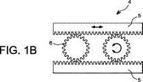
前記駆動素子と同様に前記ローリング素子に、このタイプ、接触する前記素子間にスライドすることが防止されることが可能な係合と決められた間隔を保持するためにさらなる手段を用いずに前記ローリング素子間に維持される前記間隔の歯を備えることは有利でありうる。図1Bにおいて、そのような装置4は、前記システムの前記部分と接続され、歯を備え、互いに対して並進運動する、二つの第1素子5を含む。そして、それらの間に、第1駆動素子5と係合可能な歯を備えた第2素子6が回転することができる空間を画定する。The rolling element as well as the drive element is of this type, without any further means to maintain a defined spacing with engagement that can be prevented from sliding between the contacting elements.It may be advantageous to have said spacing teeth maintained between the rolling elements. 1B, the such device 4 is connected to the portion of the system, with teeth, it translatesagainst each other, comprising a
この二つの説明される例は、数個の別形を有してもよい。図1Aにおける回転する前記ベアリングは、二つの平面間に位置する前記円柱を駆動し、一方が他方に対して平行に並進運動する二つの平面を有するスライディング補助として、丸太の上での移動の方法で、作られてもよい。図1Cに説明されるほかの実施例は、相対的な可動素子、ここでは、第3素子9に関して可動する二つの棒8を含む球体の被駆動素子7のためのガイディングケージ(une cage de guidage)の存在に関する。さらに、すべての前記可動素子2、5、8、9または、それらのうちの数個は、そのような前記機械システムの部分、前記単独の被駆動素子3、6、7によって提供される前記補助を形成してもよい。 The two described examples may have several variants. The rotating bearing in FIG. 1A drives the cylinder located between two planes, a method of movement on a log as a sliding aid with two planes, one of which translates parallel to the other. And it may be made. Another embodiment illustrated in FIG. 1C is a guiding cage for a relative driven element, here a spherical driven element 7 comprising two rods 8 which move relative to a third element 9. guidage). Furthermore, all the
本発明は、図2から図7に描写される例10のすべての装置に適用されてもよい。それらは、独立していてもよく、または、より複雑なシステムの動作を補助してもよい。より複雑なシステムは、少なくとも二つの駆動素子12、14を含み、それらが互いに関して可動し、それらの間に空間16を決め、そこでは、少なくとも一つの被駆動素子18が前記駆動素子12、14の前記相対的な動作中のローリングを介して動くものである。前記被駆動素子18は、実際には、その機械的な接触を介してそれぞれの前記駆動面と接するのみである。前記の様々な素子12、14、18の配置とそれらの形状は前記装置の利用法によって決まる。 The present invention may be applied to all the devices of Example 10 depicted in FIGS. They may be independent or may assist in the operation of more complex systems. A more complex system includes at least two
本発明によれば、前記素子12、14、18のうちの一つは、電気的に絶縁している伝導帯、具体的には、絶縁部の存在を介し、一つ以上の他の素子のレベルでか、または、同一の素子内に位置することが可能な前記装置10の伝導部を、含む。電位差は、このように、前記関係する素子の前記伝導帯とそのような前記装置10の前記伝導部の間に作り出される。本発明によれば、前記伝導帯はある一定の間隔によって前記伝導部から離間されており、そして、前記装置は、前記駆動素子の相対的な変位中に、ひいては前記被駆動素子の回転中に、その間隔が変化するように配置される。According to the present invention, one of the
その間隔の変化は、前記伝導帯/伝導部のアセンブリの前記キャパシタンスの変化と一体となっており、それらの間の前記素子12、14、18の前記相対的な動作中、時間および/または空間における前記キャパシタンスの変化は生み出される。それは、計測され、および/または、適切な手段を介して電気エネルギーに変換されることが可能であり、その例として、ここでは詳細な説明を省くが、Meninger S et coll.:≪Vibration-to-electric Energy Conversion≫, IEEE Transactions on Very Large Scale Integration (VLSI) System; 2001,9(1):64-76 が知られている。 The change in spacing is integral with the change in capacitance of the conduction band / conducting assembly, during the relative operation of the
間隔変化により、前記伝導部と前記伝導帯は、その寸法が物理的に変化する絶縁空間、または、前記変位に応じて結果的に生じる誘電率が異なる値を取るように、様々の相対的な配置を取ることが可能である、不連続の誘電体媒質(un milieu dielectrique discontinu)を含む固定された空間、によって離間される。具体的には、前記誘電体媒質は、絶縁域と伝導域を含む。前記伝導帯と伝導部間に位置する前記絶縁域における電子の経路が、前記伝導域の位置(図2A参照)に応じて異なるように、前記絶縁域は、前記伝導帯(各部)を延長することが可能であるか、または、それから離間されるものである。実際には、伝導“帯”と伝導“部”は、必ずしも物理的な要素と一致している必要はないが、前記装置の動作とその構成要素の配置に応じて、本発明による前記装置の異なる部分と一致していてもよい。 Due to the change in the spacing, the conductive part and the conductive band may have various relative values such that the dimensions of the conductive part and the conductive band are physically changed, or the resultant dielectric constant varies depending on the displacement. Spaced by a fixed space containing an unmilieu dielectrique discontinu, which can be arranged. Specifically, the dielectric medium includes an insulating region and a conductive region. The insulating region extends the conduction band (each part) so that the electron path in the insulating region located between the conduction band and the conduction portion differs depending on the position of the conduction region (see FIG. 2A). Is possible or is spaced from it. In practice, the conduction “band” and the conduction “portion” do not necessarily coincide with physical elements, but depending on the operation of the device and the arrangement of its components, the device according to the invention It may coincide with a different part.
前記伝導帯は、このように、変位の方向に絶縁部と交互に、駆動素子または被駆動素子に組み込まれてもよい。前記伝導部は、ほかの素子、そしてさらに、前記必要な伝導帯と絶縁部を除く前記装置のアセンブリ、からも全体に構成されてもよい。前記間隔変化は、前記被駆動素子内に、または、その動作のため、発生する可能性がある。前記間隔の変化は、伝導帯と伝導部を離間する絶縁部の適切な位置決めによって提供されてもよい。 Thus, the conduction band may be incorporated in the driving element or the driven element alternately with the insulating portion in the direction of displacement. The conductive portion may be entirely composed of other elements and, further, the assembly of the device excluding the necessary conductive band and insulating portion. The spacing change may occur in the driven element or due to its operation. The change in the distance may be provided by appropriate positioning of the insulating part separating the conduction band and the conductive part.
簡単な例として、図2Aを考慮すれば、伝導性の前記駆動素子14は、伝導性があり絶縁層で覆われた前記駆動素子12に対して平行にスライドしている。その相対的なスライディング動作は前記ローリング素子18を駆動する。そのローリング素子は、前記駆動素子12、14の互いに対してどんな変位も可能にする球体か、あるいは、軸上で垂直な並進を可能とする円柱であってもよい。前記ローリング素子は、伝導部18cと絶縁部18iを含む。回転のため、前記伝導帯12の前記電位と前記伝導部14の電位間の前記間隔は、前記伝導部14を延長する前記伝導部18cの場所に応じて異なる。(それは、固定された間隔によって離間される前記駆動素子12、14間の結果として生じる誘電率が変化することを意味する。)したがって、前記駆動素子12、14間のキャパシタンスは変化し、適切な手段で確認および計測することができる。静電法を介して、このようにして、前記表面12、14の前記変位と関係がある機械エネルギーの一部を電気エネルギーに変換することが可能である。As a simple example, considering FIG. 2A, the
前記絶縁部18iと伝導部18cの構造によれば、もし前記駆動素子12、14間の電気接触が可能でないならば、例えば、もし前記絶縁部18iが前記ローリング素子18の円周の半分以上を含むならば、前記駆動素子12の一つである絶縁層20を覆わないことが可能である。 According to the structure of the insulating
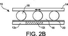
図2Bでは、前記実施例の別形は、実際に駆動素子14の一つからなる前記伝導部を延長する、伝導性のある被駆動素子18を全体に含んでもよい。絶縁層20で覆われている他の駆動素子12は、さらに、この場合、前記ローリング素子18の変位の方向に前記伝導帯12cを離間する絶縁部12iを含む。前記駆動素子12、14の相対的な変位中に、前記ローリング素子18は、前記伝導帯12cまたは前記絶縁体12i上を通過し、前記伝導部14、18と伝導帯12c間の間隔は、前記絶縁層20の最小の厚みと前記絶縁部12iの幅の半分以上の間で変化し、このようにしてキャパシタンス変化を生みだす。 In FIG. 2B, another embodiment of the embodiment may include a conductive driven
図2Cでは、さらに、前記実施例の別形は、二つの可変キャパシタンスが同時に作られることを可能にする。絶縁部12iは、ここでは、異なる等電位面V1とV2を接続する伝導帯12c1と12c2を離間するのにちょうど十分な厚さに減少される。前記キャパシタンス変化は、前記被駆動素子18が、第2駆動素子12の等電位面V1またはV2のどちらかで、第1駆動素子14の定電位Vに接近するという事実に固有のものであり、このようにして、電位Vおよび電位V1とV2間のキャパシタンス変化を生みだし、あるいは、キャパシタンス変化は、前記伝導部12cの様々な電位V1とV2間に発生することができる。In FIG. 2C, the variant of the embodiment further allows two variable capacitances to be created simultaneously. Insulating
前記絶縁部12iは、前記被駆動素子18のローリングの方向に対して垂直な一定間隔の線を、または、もし球体形状の前記ローリング素子による双方向の変位が可能であるならば、格子縞模様を、形成するという利点がある。 同一の駆動素子12に対して二つ以上の等電位面を有する、他の形状も可能である。 The insulating
ほかの別形は、図3Aと3Bに説明されており、前記駆動素子12の一つは“物理的に”離間される伝導帯121、122を含む。ここでは再び、前記球体のローリング素子18は、球体の配置に応じて、異なる電位に位置する前記伝導帯121、122を離間する間隔をおおよそ覆う絶縁部18iを含む。前記駆動素子14が二つの駆動棒に対して平行に動く時、前記ボール18はロールし、その伝導部18cは、前記棒121、122のいずれか一方または他方、そして、そのため、電位V1及びV2のどれかと、機械的接触により電気的に接続される。二つの電位V1及びV2を離間する間隔は、前記キャパシタンスと同様に変化する。前記被駆動素子18の絶縁部18iの形状とサイズは、もちろん、所望される結果に応じて、例えば、前記様々なローリング素子18の伝導素子18c間の前記キャパシタンス変化にとってより好ましい効果を得るために、適合させることができる。 Another variant is illustrated in FIGS. 3A and 3B, where one of the
注目すべきは、前記実施例において、例えば、内蔵センサーのような電気エネルギーを使用するための手段を用いて、前記キャパシタンス変化を前記ローリング素子18において直接使用することが可能であることである。 It should be noted that in the embodiment, the capacitance change can be used directly in the rolling
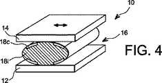
被駆動素子18の内部のそのような利用法はまた、変形可能な素子18について同じと考えてもよい。図4に説明されるひとつの実施例によれば、前記ローリング素子18は、例えば、所々に金属被覆された重合体のボール18iのような、伝導部18cを包含する変形可能な円柱または球体を含む。前記駆動部14が前記駆動部12と平行に動く時、空間16に圧縮状態で位置する前記被駆動素子18は、一方向または双方向に、変形し、ロールする。その変形は、前記の様々な伝導部18c間の間隔変化、ひいては、キャパシタンス変化をもたらし、例えば、センサーに電力を供給するのに(pour alimenter un capteur)使用されるために、前記被駆動素子18それ自体の内部に電気を生みだすことができる。前記実施例ではまた、周辺の伝導性の接触を用いて、キャパシタンス変化、または外部に向かって電気エネルギーをもたらすことが可能である。 Such usage within the driven
一般に、前記キャパシタンス変化は、ローリング素子18の内部、および/または、ローリング素子の間、または、前記被駆動素子18と駆動素子12、14の間、または、前記駆動素子12、14の内部、または空間16において、起こる可能性がある。さらに、被駆動素子の形状のすべては、固体円柱または変形可能な円柱、鋸歯状の歯車または鋸歯状の円柱、固体球または変形可能な球体を考えられることが可能である。前記駆動素子12、14は、通常個体であり、絶縁可能な部分を含む伝導性の金属において作られる。動作の構造、および前記駆動素子の性質によれば、前記ローリング素子18は、表面上に部分的に金属被覆された絶縁物質、または伝導性の挿入物(inserts)を含む物質、に製造されてもよく、または、絶縁性、および伝導性の部分をさらに含んでいてもよい。 In general, the capacitance change may occur within the rolling
図5では、具体的に、さらなる形状の、第2スライディング被駆動素子28とローリング被駆動素子18を関連づけることが可能である。前記駆動素子12、14に関して前記スライデイング素子28の相対的な位置は、回転との組み合わせなしに、前記変位の方向に変わるのみである。逆に、軸または点の周りを回転中に、前記ローリング素子18は、前記スライディング素子28に異なる面を引き合わせる。具体的には、前記駆動素子12、14と前記ローリング素子18のその連続的な部分は同一の電位Vにあるので、そのスライディング素子28は、異なる等電位面V1、V2、V3の三つのゾーン281、282、283(281については前記駆動素子12、14の影響を、282、283については主に二つの連続的なローリング素子18の影響を、それぞれ受けている)を有していてもよい。前記ローリング素子18の前記伝導部18cと前記スライディング素子28の対応するゾーン282、283間の間隔によれば、すなわち、前記ローリング素子18の絶縁部18iの相対的な位置によれば、キャパシタンスは異なり、キャパシタンス変化は、VとV2またはV3の間で生みだされる。同様に、前記の様々な等電位面V1、V2、V3は、すべて、二つずつであることがわかり、キャパシタンス変化は電気エネルギーをスライディング素子28内に配置されるようにする。 In FIG. 5, specifically, the second sliding driven
もちろん、電位一つずつの間のキャパシタンス変化を増幅するため、VとV1の間のキャパシタンス変化が生み出されるように、あるいはV2(またはV3)とVの間で生みだされるキャパシタンス変化と一致して、前記スライディング素子28と前記素子12、14のその駆動表面の間に構造を有することが可能である。 Of course, in order to amplify the capacitance change between the potentials one by one, a capacitance change between V and V1 is produced, or coincides with a capacitance change produced between V2 (or V3) and V. Thus, it is possible to have a structure between the sliding
ここまで、前記駆動素子が一方から他方に対して平行にスライドする“スライドレール”構造について記載してきたが、本発明は、前記駆動素子12、14が互いに対して回転する前記“ボールベアリング”構造にも全く同様に当てはまる。そして、さらに上記実施例は、説明される前記駆動素子を“内側に曲げること”によって、そして環状の空間16を形成するために前記駆動素子を包囲することによって、すぐに適合する。 So far, the "slide rail" structure in which the drive element slides in parallel from one to the other has been described, but the present invention describes the "ball bearing" structure in which the
実施例は図6に詳述される。環状の空間16は、伝導性の駆動素子12に関して前記軸14の相対的な回転を介して伝導性の被駆動素子18の誘導されるローリングを可能にする。中央部14は、リング12に関して、軸14のある一定の角度の位置において、大きなキャパシタンスを、ほかでは、小さなキャパシタンスを形成するような方法で分布される伝導性のセクター(secteurs)の離間を可能にする絶縁性の部分14iを含む。もしこれらの伝導性のセクターが二つの等電位面V1とV2に一緒に組み立てられるなら、前記二つの等電位面の間のキャパシタンスの時間的変化は、前記素子12、14、18のそれぞれの相対的な回転中に得られる。 An example is detailed in FIG. The
また、同一の電位にすべての前記セクターを一緒に組み立てる駆動素子12と前記軸14の間のキャパシタンス変化を得ること、例えば、V1とV2を短絡化することによって、および前記回転素子14とその外側の素子12間のキャパシタンス変化を想定すること(visualisant)によって、も可能である。 Also, obtaining a capacitance change between the
またこの実施例において、さらなる変位は、回転軸に対して垂直な方向に、前記駆動装置12、14の並進と組み合わされることができる。 Also in this embodiment, further displacement can be combined with the translation of the
この実施例において、図2Cの実施例の場合のように、前記軸の外面上に格子縞模様または線を位置付けることが可能である。さらに、もし前記外側部分12に電気エネルギーを有することが望まれるならば、その役割は、例えば、格子縞模様の前記リング12の内面のコーティングで打ち消される可能性がある。 In this embodiment, it is possible to position a checkered pattern or line on the outer surface of the shaft, as in the embodiment of FIG. 2C. In addition, if it is desired to have electrical energy in the
具体的には、回転構造のため、側面のガイドは、前記ローリング素子18が、その回転中に前記空間16から出てくることを防止するように、前記駆動素子12、14のどちらか一方、または両方の上に、しばしば存在する。そのため、このタイプのガイドをさらにうまく利用することが可能である。 Specifically, because of the rotational structure, the side guides are either one of the
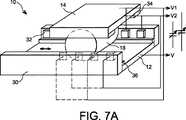
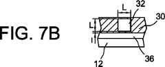
このようにして、例えば、図7に説明される装置において、前記ローリング素子18と前記駆動面12、14は、伝導性で、および同一の電位Vにある。平面に描かれているが、前記構造は“ボールベアリング”に使用されることができる。そのため、前記面12、14は環状で、例えば、5.5cmの内径および7.5cmの外径を有する環状形状であって、具体的には、長さが24cmで幅が2.5cmの外側のローリング面14であってもよい。説明される前記骨組み内部には、前記被駆動素子は、直径d=1cmおよび長さE=2cmの伝導性の円柱18がある。前記駆動面のひとつは、少なくともガイド手段に付随している。いかなる摩擦も防止するために、前記ガイド手段の間の自由な空間は、前記円柱18の長さEよりも長いことが好ましい。 Thus, for example, in the apparatus illustrated in FIG. 7, the rolling
前記駆動素子12のひとつに付随する前記ガイド手段30は絶縁体で、伝導帯32を除いて、一方から他方まで絶縁性であり、前記ローリング素子18の変位の方向に沿って位置付けられる。前記伝導帯は、壁30に組み入れられるか、又は、突出させてもよい。しかしながら、最小のギャップhは、前記伝導帯32とローラー18間の動作中に、供給されねばならず、少なくともそれらにとって、キャパシタンス変化の計測および/または使用に役立つ。図例において、前記ギャップhが約0.1mmであるのは有利である。 The guide means 30 associated with one of the
前記ローリング素子18の動作をより正確に誘導するために、ガイド手段34は、ほかの駆動素子14のどちらか側上に、例えば、突起に位置づけられてもよい。さらに、前記ギャップhの間隔を提供するため、伝導帯32を有する前記ガイド素子30を含む前記駆動素子12上にスペーサー(une butee)36を位置付けることも可能である。 In order to guide the operation of the rolling
その機械的な接触のため、前記被駆動素子18と駆動素子12、14、36(随意に前記ガイド手段34も同様に)は同一の等電位面Vにある。前記外側のリング14が前記円柱12の回りを動く時、前記素子18は回転およびロールされる。それらは、交互に前記伝導帯32の前を通過する。前記伝導帯32の数は、前記ローリング素子18の数の倍数であって、前記環状の空間16の周囲に沿う各側に一様に分布される、例えば、6個のローリング素子と12組の伝導帯32である、のは有利であり、前記ローリング素子18は、例えば挿入物により提供されてもよい。前記伝導帯32は、前記装置10の等電位面Vと異なる、一つ以上の等電位面V1、V2と連結していてもよい。すなわち、駆動素子12、14と被駆動素子18である。前記ローラー18の変位はまた前記等電位面Vと前記伝導素子32間のキャパシタンス変化を生みだす。電気エネルギーの回収に使用できる変化であり、前記の様々な伝導素子32と等電位面Vの前記の様々な素子間の電圧を連続的に適用することにより、アクチュエーターとして前記構造10を相互に利用しやすい。 Due to the mechanical contact, the driven
前記実施例において、前記不連続の素子32を連続する伝導層に、および、全体的に伝導性であるローリング体18を伝導性のセクターと絶縁性のセクターを含むローリング体に、代えても提供され得る。 In the embodiment, the
説明される好ましい実施例によれば、前記伝導帯32は、一列に並べられるとき前記ローリング素子18の端面によって90%まで覆われてもよく、および、ローリング段階中にこれらの同一の素子から全体的に分かれ出てもよい。 例えば、それは、ローリング方向に1cmの間隔をあけるL側上の1cmの正方形に関し、厚みe=0.1mmを有し、絶縁壁30に配置され、底面から一定の間隔を空けられていて、ここでは、lが1mmとして前記スペーサー(la butee)36の突起により示される。他の実施例すべてに関しては、通常の技術が本発明による前記装置10を製造するために使用されてよく、具体的には、機械的な機械加工(フライス盤、旋盤、スパーク加工、など)、またはモールディング(le moulage)が前記の様々な素子を作られることを可能にする。原料の選択は、作られるものの利用法次第である。 According to the preferred embodiment described, the
二つの一定の間隔を空けられた構成要素間のキャパシタンスCは、間隔Dにより間隔をあけられるε0空気の誘電率と前記構成要素上のS面により、C=ε0・S/D により与えられる。The capacitance C between two regularly spaced components is given by C = ε0 · S / D, due to the dielectric constant of ε0 air spaced by the spacing D and the S-plane on the component. It is done.
前述の構造において、覆われるためのD=h=0.1mmの間隔を有する前記面32の前を定期的に通過する6個のローリング円柱18を有する、前記伝導素子32の電位と前記ローリング素子/駆動素子のアセンブリの間に最大のキャパシタンスがある:
最小のキャパシタンス、それ自体は、主に前記伝導素子32上の前記面と駆動素子12、36からなる:
このキャパシタンスCminは、前記伝導素子32に対して丸みのある形状を取ること、またはその中央のみが伝導性の駆動面12を用いること、により自然に最小限に抑えられることができる。エネルギー回収のためのこの改良は実施されるが、製作の簡潔さと頑健性(la robustesse)に被害が及ぶ。さらに、上記でなされた選択は、存在するローリングベアリング(または動作を補助するほかのいかなるシステム)が本発明による装置になるように適合されることを可能にする。This capacitance Cmin can be naturally minimized by taking a rounded shape with respect to the
U=V−V1=15Vと等しい電圧をチャージすることで “一定の充電で (a charge constante) ”として知られる動作に対して、サイクル毎に回収されることが可能なそのエネルギーは、したがって:
である。For an operation known as “a charge constante” by charging a voltage equal to U = V−V1 = 15V, the energy that can be recovered per cycle is therefore:
It is.
前記軸12の1回転に対して、前記の使用と並行する、VとV1の間、およびVとV2の間の容量変化中に、2×3サイクルの容量変化がある。したがって、6×7.35=44.1μWが回転/秒ごとに、すなわち、毎分1500回転に対して、1.1mWが得られる。もし15Vの充電電圧を取る代わりに、100Vが取られるなら、毎分1500回転の同一スピードに対して49mWが得られる。これらのふたつの電力は、一つ以上のセンサー、同様にデータの無線送信を供給するために十分なエネルギーを回収するのに十分である。 For one revolution of the
実際に、それは前記充電電圧を電気エネルギーの要求に適応させるのに十分である。しかしながら、より多くの電気エネルギーが作り出されれば、より多くの機械エネルギーが前記軸12に吸収され、ひいては、前記装置10の自然の動作を阻害するリスクがより高くなるということを念頭に置くことが必要である。 In fact, it is sufficient to adapt the charging voltage to the electrical energy requirements. However, keep in mind that if more electrical energy is created, more mechanical energy is absorbed by the
その規模(le dimensionnement)は、その利用法に応じて様々な値を取ってもよい。具体的には、その寸法は、大型トラックタイプの車両の車軸に対しては大いに増大されうるし、また時計製造における用途に対しては大いに制限されうる。さらに、説明される前記の様々な実施例の別形は組み合わされてもよい。 The dimension (le dimensionnement) may take various values depending on the usage. Specifically, the dimensions can be greatly increased for heavy truck type vehicle axles and can be greatly limited for applications in watchmaking. Furthermore, variations on the various embodiments described above may be combined.
本発明によれば、このようにして、互いに関して相対的に可動する少なくとも二つの面の間で、ローリングまたはスライディングを介して動作する一つ以上のローリング素子により生みだされるキャパシタンス変化から、電気回路、センサー、または他のものを供給するために使用される電気エネルギーを、静電法を介して、生みだすことが可能である。前記キャパシタンスの変化は、例えば、電子機器のための可変キャパシタンスの生成、前記ローリング素子の位置のセンサーとしての直接的な計測、角度位置、または機械的なベアリングのアーマチャーの回転のスピードの計測など、様々なタイプの用途に用いられることができる。 In accordance with the present invention, in this way, from capacitance changes produced by one or more rolling elements operating via rolling or sliding between at least two surfaces that are movable relative to each other, The electrical energy used to supply a circuit, sensor, or others can be generated via electrostatic methods. The change in capacitance may include, for example, generation of variable capacitance for electronic equipment, direct measurement as a sensor of the position of the rolling element, angular position, or measurement of the rotational speed of a mechanical bearing armature, etc. It can be used for various types of applications.
このように、ローラーベアリングの電気エネルギーを生成するために使用されることが可能であるキャパシタンス変化を生みだす前記ローリング素子を活用して動作中の部分を誘導および供給すること、および存在する機械的なベアリングに前記原理を適用することが可能である。さらに、本発明による前記装置は、逆方向の動作をすること、すなわち、電気エネルギー源から機械的な動作を生みだすこと、および機械的なアクチュエーターを製造すること、が可能である。 In this way, the rolling element that produces the capacitance change that can be used to generate the electrical energy of the roller bearings is utilized to induce and supply the operating part and the existing mechanical It is possible to apply the principle to a bearing. Furthermore, the device according to the invention is capable of working in the reverse direction, i.e. producing mechanical motion from an electrical energy source and producing mechanical actuators.
前記ローリング部は、本発明によれば、二つの目的の対象(l’objet d’un double emploi)、機械的なガイド、および容量変化のジェネレータ(generateur)である。さらに、それらは変形可能であってもよい。According to the present invention, the rolling part is atwo- purpose object (l'objet d'un double emploi), a mechanical guide, and a capacity change generator. Furthermore, they may be deformable.
本発明による前記システムはまた、機械的な加速(accelerations mecaniques)、流体運動、または他のものから発生する、自由なローリング動作からそのエネルギーを回収することを可能にする。例えば、本発明によるボールベアリングの回転中の軸は、加速の影響下にあるとき、前記ボールの動作、同様にその慣性のため外側のリングの動作を生み出す。その結果、電気エネルギーに変換可能であるキャパシタンス変化が起きる。このようにして、外部のものとの接続なしに、軸上にエネルギーを有することが可能であり、消費者装置まで電気エネルギーをもたらすための特定の電源および電気伝導体を供給することを必要としない。The system according to the invention also makes it possible to recover its energy from free rolling movements arising from mechanical accelerations, fluid motion, or others. For example, the rotating shaft of a ball bearing according to the present invention, when under the influence of acceleration, produces movement of the ball as well as movement of the outer ring due to its inertia. The result is a capacitance change that can be converted to electrical energy. In this way, it is possible to have energy on the shaft without connection to the outside, and itis necessary to supply specific power sources and electrical conductors to bring electrical energy to the consumer deviceNot .
10 装置
12 駆動素子
14 駆動素子
16 空間
18 ローリング素子
18c 伝導部
18i 絶縁部
121 伝導帯(部)
122 伝導帯(部)
20 絶縁層
28 スライディング素子
282 伝導帯(ゾーン)
30 絶縁部DESCRIPTION OF
122 conduction band
20 Insulating
30 Insulation part
Claims (19)
Translated fromJapanese前記空間(16)において、前記駆動素子(12、14)の動作により駆動されて移動可能な機械的な接触をしている、少なくとも一つのローリング素子(18)と、
キャパシタンスの変化を電気エネルギーに変換する手段、とを
備える装置であって、
その装置(10)は、少なくとも1つの伝導部と少なくとも1つの伝導帯とを備え、前記伝導帯は、それらの間で、前記素子(12、14、18)の相対的な変位中に、前記伝導帯と前記伝導部の間のキャパシタンスが変化するように、間隔を変えることにより、伝導部から絶縁され、離間することを特徴とする、可変キャパシタンスを有する装置(10)。At least two drive elements (12, 14) movable relative to each other and defining a space (16) between each other;
In the space (16), at least one rolling element (18)that is driven by the operation of the drive element (12, 14) and has movable mechanical contact ;
It means for converting a changein capacitance into electrical energy,the capital
A device comprising:
The device (10)comprises at least one conduction part and at least one conduction band, said conduction bandbetween them during said relative displacement of said element (12, 14, 18) A device (10) havinga variable capacitance, characterized in that it is insulated and spaced from the conducting part by changing thespacing so that the capacitance between the conducting band and the conducting part changes.
Applications Claiming Priority (3)
| Application Number | Priority Date | Filing Date | Title |
|---|---|---|---|
| FR0552113AFR2888419B1 (en) | 2005-07-08 | 2005-07-08 | VARIABLE CAPACITY GENERATING DEVICE FOR GENERATING ELECTRIC ENERGY AND BALL BEARING MOTION ASSISTING DEVICE INCLUDING THE SAME |
| FR0552113 | 2005-07-08 | ||
| PCT/EP2006/063983WO2007006731A1 (en) | 2005-07-08 | 2006-07-06 | Device for assisting the variable capacity generating movement |
Publications (2)
| Publication Number | Publication Date |
|---|---|
| JP2009500995A JP2009500995A (en) | 2009-01-08 |
| JP5032471B2true JP5032471B2 (en) | 2012-09-26 |
Family
ID=36190644
Family Applications (1)
| Application Number | Title | Priority Date | Filing Date |
|---|---|---|---|
| JP2008519942AExpired - Fee RelatedJP5032471B2 (en) | 2005-07-08 | 2006-07-06 | Device for assisting movements that produce variable capacitance |
Country Status (5)
| Country | Link |
|---|---|
| US (1) | US8174163B2 (en) |
| EP (1) | EP1902514A1 (en) |
| JP (1) | JP5032471B2 (en) |
| FR (1) | FR2888419B1 (en) |
| WO (1) | WO2007006731A1 (en) |
Families Citing this family (8)
| Publication number | Priority date | Publication date | Assignee | Title |
|---|---|---|---|---|
| FR2888419B1 (en)* | 2005-07-08 | 2010-12-03 | Commissariat Energie Atomique | VARIABLE CAPACITY GENERATING DEVICE FOR GENERATING ELECTRIC ENERGY AND BALL BEARING MOTION ASSISTING DEVICE INCLUDING THE SAME |
| FR2889371A1 (en) | 2005-07-29 | 2007-02-02 | Commissariat Energie Atomique | DEVICE FOR CONVERTING MECHANICAL ENERGY IN ELECTRIC ENERGY BY CYCLE OF ELECTRICAL LOADS AND DISCHARGES ON THE CONNECTORS OF A CAPACITOR |
| US7719164B2 (en)* | 2008-08-06 | 2010-05-18 | Honeywell International Inc. | Patterned dielectric elastomer actuator and method of fabricating the same |
| FR2936351B1 (en)* | 2008-09-25 | 2010-10-15 | Commissariat Energie Atomique | VARIABLE CAPACITY SYSTEM WITH FLEXIBLE DIELECTRIC. |
| US10333430B2 (en)* | 2014-11-25 | 2019-06-25 | Georgia Tech Research Corporation | Robust triboelectric nanogenerator based on rolling electrification |
| WO2019161256A2 (en) | 2018-02-15 | 2019-08-22 | The Charles Stark Draper Laboratory, Inc. | Electrostatic motor |
| WO2021138690A1 (en)* | 2020-01-03 | 2021-07-08 | C-Motive Technologies, Inc. | Electrostatic motor |
| JP7528850B2 (en)* | 2021-04-12 | 2024-08-06 | トヨタ自動車株式会社 | Actuator |
Family Cites Families (19)
| Publication number | Priority date | Publication date | Assignee | Title |
|---|---|---|---|---|
| US2266057A (en)* | 1933-02-13 | 1941-12-16 | Massolle Joseph | Electrostatic converter |
| US3107326A (en)* | 1960-05-25 | 1963-10-15 | High Voltage Engineering Corp | Variable capacitance electrostatic generator |
| US3412318A (en)* | 1964-11-18 | 1968-11-19 | United Shoe Machinery Corp | Variable capacitor electric power generator |
| US3414742A (en)* | 1966-10-12 | 1968-12-03 | Marvin J. Fisher | Electrostatic energy converter |
| US4225801A (en)* | 1979-05-15 | 1980-09-30 | Parker Jr Charles M | Electrostatic motor |
| US4789802A (en)* | 1987-01-24 | 1988-12-06 | Japan Physitec Co., Ltd. | High voltage, multi-stage electrostatic generator |
| US4871266A (en)* | 1987-06-24 | 1989-10-03 | Ngk Insulators, Ltd. | Slide assemblies |
| JPS6412877A (en)* | 1987-07-02 | 1989-01-17 | Seiko Instr & Electronics | Electrostatic actuator |
| JPH01107667A (en)* | 1987-10-19 | 1989-04-25 | Sanyo Electric Co Ltd | Electrostatic motor |
| US4922164A (en)* | 1988-10-03 | 1990-05-01 | Sarcos Group | Eccentric motion motor |
| US5237234A (en)* | 1988-10-13 | 1993-08-17 | At&T Bell Laboratories | Harmonic electrostatic motor |
| ES2020013A6 (en)* | 1988-10-20 | 1991-07-16 | Univ Madrid Nac Educacion | Rotating triboelectric generator |
| US5093594A (en)* | 1990-06-22 | 1992-03-03 | Massachusetts Institute Of Technology | Microfabricated harmonic side-drive motors |
| JPH05300759A (en)* | 1992-04-17 | 1993-11-12 | Yaskawa Electric Corp | Electrostatic actuator |
| JP2000152669A (en)* | 1998-11-05 | 2000-05-30 | Panetto:Kk | Micro actuator |
| US6218803B1 (en)* | 1999-06-04 | 2001-04-17 | Genetic Microsystems, Inc. | Position sensing with variable capacitance transducers |
| JP2002083736A (en)* | 2000-09-11 | 2002-03-22 | Murata Mfg Co Ltd | Variable capacitor |
| GB0114711D0 (en) | 2001-06-15 | 2001-08-08 | South Bank Univ Entpr Ltd | Portable electricity generator |
| FR2888419B1 (en)* | 2005-07-08 | 2010-12-03 | Commissariat Energie Atomique | VARIABLE CAPACITY GENERATING DEVICE FOR GENERATING ELECTRIC ENERGY AND BALL BEARING MOTION ASSISTING DEVICE INCLUDING THE SAME |
- 2005
- 2005-07-08FRFR0552113Apatent/FR2888419B1/ennot_activeExpired - Fee Related
- 2006
- 2006-07-06JPJP2008519942Apatent/JP5032471B2/ennot_activeExpired - Fee Related
- 2006-07-06USUS11/994,125patent/US8174163B2/ennot_activeExpired - Fee Related
- 2006-07-06WOPCT/EP2006/063983patent/WO2007006731A1/ennot_activeApplication Discontinuation
- 2006-07-06EPEP06792484Apatent/EP1902514A1/ennot_activeWithdrawn
Also Published As
| Publication number | Publication date |
|---|---|
| FR2888419B1 (en) | 2010-12-03 |
| US20080211342A1 (en) | 2008-09-04 |
| EP1902514A1 (en) | 2008-03-26 |
| WO2007006731A1 (en) | 2007-01-18 |
| US8174163B2 (en) | 2012-05-08 |
| FR2888419A1 (en) | 2007-01-12 |
| JP2009500995A (en) | 2009-01-08 |
Similar Documents
| Publication | Publication Date | Title |
|---|---|---|
| JP5032471B2 (en) | Device for assisting movements that produce variable capacitance | |
| US9362849B2 (en) | Electrostatic induction power generator | |
| CN102637515B (en) | Rotary transformer and the rolling bearing system with rotary transformer | |
| EP3394976B1 (en) | Power generation or conversion system | |
| JPH1198868A (en) | Electrostatic power generation device | |
| JP6779116B2 (en) | Flexible meshing gear device | |
| US20140252914A1 (en) | Electrostatic generator/motor designs capable of operation with the electrodes immersed in a liquid or pressurized gas | |
| CN113241966A (en) | Rotary friction nano power generation device and method based on point discharge | |
| US5501604A (en) | Flexible band-gears for conducting power/signal across rotary joint | |
| KR101811958B1 (en) | Gyroball type generator | |
| CN110323648A (en) | A kind of roller collector machine | |
| WO2021177354A1 (en) | Bearing assembly with load detection functionality and bearing assembly with power generation functionality | |
| JP7074500B2 (en) | bearing | |
| CN115088159A (en) | Bearing device, spacer and manufacturing method | |
| JPWO2011089699A1 (en) | Power generation device and power generation method | |
| CN112834213B (en) | Gearbox state monitoring system | |
| CN105043618B (en) | A kind of electric capacity torque sensor | |
| KR100353457B1 (en) | Piezoelectric step motor | |
| CN104919199A (en) | Bearing power generating configuration | |
| JP7497547B2 (en) | Bearing device with power generation function | |
| KR102790405B1 (en) | Self-powered shaft encoder based on triboelectric nanogenerator | |
| RU2662220C2 (en) | Current-transmission element | |
| JP2004273406A (en) | Method of current collection without slippage | |
| JP2021139431A (en) | Bearing device with load detection function | |
| CN112780669B (en) | A roller bearing with monitoring device |
Legal Events
| Date | Code | Title | Description |
|---|---|---|---|
| A621 | Written request for application examination | Free format text:JAPANESE INTERMEDIATE CODE: A621 Effective date:20090630 | |
| A131 | Notification of reasons for refusal | Free format text:JAPANESE INTERMEDIATE CODE: A131 Effective date:20111220 | |
| A601 | Written request for extension of time | Free format text:JAPANESE INTERMEDIATE CODE: A601 Effective date:20120319 | |
| A602 | Written permission of extension of time | Free format text:JAPANESE INTERMEDIATE CODE: A602 Effective date:20120327 | |
| A601 | Written request for extension of time | Free format text:JAPANESE INTERMEDIATE CODE: A601 Effective date:20120419 | |
| A602 | Written permission of extension of time | Free format text:JAPANESE INTERMEDIATE CODE: A602 Effective date:20120426 | |
| A521 | Request for written amendment filed | Free format text:JAPANESE INTERMEDIATE CODE: A523 Effective date:20120507 | |
| TRDD | Decision of grant or rejection written | ||
| A01 | Written decision to grant a patent or to grant a registration (utility model) | Free format text:JAPANESE INTERMEDIATE CODE: A01 Effective date:20120529 | |
| A01 | Written decision to grant a patent or to grant a registration (utility model) | Free format text:JAPANESE INTERMEDIATE CODE: A01 | |
| A61 | First payment of annual fees (during grant procedure) | Free format text:JAPANESE INTERMEDIATE CODE: A61 Effective date:20120628 | |
| R150 | Certificate of patent or registration of utility model | Free format text:JAPANESE INTERMEDIATE CODE: R150 | |
| FPAY | Renewal fee payment (event date is renewal date of database) | Free format text:PAYMENT UNTIL: 20150706 Year of fee payment:3 | |
| R250 | Receipt of annual fees | Free format text:JAPANESE INTERMEDIATE CODE: R250 | |
| LAPS | Cancellation because of no payment of annual fees |