JP5025899B2 - Trocar insertion device - Google Patents
Trocar insertion deviceDownload PDFInfo
- Publication number
- JP5025899B2 JP5025899B2JP2004274252AJP2004274252AJP5025899B2JP 5025899 B2JP5025899 B2JP 5025899B2JP 2004274252 AJP2004274252 AJP 2004274252AJP 2004274252 AJP2004274252 AJP 2004274252AJP 5025899 B2JP5025899 B2JP 5025899B2
- Authority
- JP
- Japan
- Prior art keywords
- arm
- handle
- engagement feature
- expansion
- expansion member
- Prior art date
- Legal status (The legal status is an assumption and is not a legal conclusion. Google has not performed a legal analysis and makes no representation as to the accuracy of the status listed.)
- Expired - Fee Related
Links
- 238000003780insertionMethods0.000titleclaimsdescription43
- 230000037431insertionEffects0.000titleclaimsdescription43
- 231100000435percutaneous penetrationToxicity0.000claimsdescription5
- 238000013459approachMethods0.000claimsdescription3
- 230000007246mechanismEffects0.000description10
- 210000000683abdominal cavityAnatomy0.000description9
- 238000000034methodMethods0.000description9
- 210000001519tissueAnatomy0.000description7
- 210000001015abdomenAnatomy0.000description6
- 230000006835compressionEffects0.000description6
- 238000007906compressionMethods0.000description6
- 230000008878couplingEffects0.000description6
- 238000010168coupling processMethods0.000description6
- 238000005859coupling reactionMethods0.000description6
- 208000005646PneumoperitoneumDiseases0.000description5
- 238000004806packaging method and processMethods0.000description3
- 238000001356surgical procedureMethods0.000description3
- CURLTUGMZLYLDI-UHFFFAOYSA-NCarbon dioxideChemical compoundO=C=OCURLTUGMZLYLDI-UHFFFAOYSA-N0.000description2
- 210000003815abdominal wallAnatomy0.000description2
- 230000008901benefitEffects0.000description2
- 210000003195fasciaAnatomy0.000description2
- 210000000245forearmAnatomy0.000description2
- 230000006870functionEffects0.000description2
- 238000012978minimally invasive surgical procedureMethods0.000description2
- 210000004303peritoneumAnatomy0.000description2
- 238000007789sealingMethods0.000description2
- LOVXREQUMZKFCM-UHFFFAOYSA-N4-[2-[1-(1,3-benzodioxol-5-yl)propan-2-ylamino]-1-hydroxyethyl]benzene-1,2-diol;hydron;chlorideChemical compoundCl.C=1C=C2OCOC2=CC=1CC(C)NCC(O)C1=CC=C(O)C(O)=C1LOVXREQUMZKFCM-UHFFFAOYSA-N0.000description1
- 230000003187abdominal effectEffects0.000description1
- 210000000746body regionAnatomy0.000description1
- 229910002092carbon dioxideInorganic materials0.000description1
- 239000001569carbon dioxideSubstances0.000description1
- 238000005516engineering processMethods0.000description1
- 210000003811fingerAnatomy0.000description1
- 239000006260foamSubstances0.000description1
- 230000002401inhibitory effectEffects0.000description1
- 238000012423maintenanceMethods0.000description1
- 230000014759maintenance of locationEffects0.000description1
- 239000000463materialSubstances0.000description1
- 239000012528membraneSubstances0.000description1
- 238000012986modificationMethods0.000description1
- 230000004048modificationEffects0.000description1
- 230000008569processEffects0.000description1
- 230000035807sensationEffects0.000description1
- 210000003813thumbAnatomy0.000description1
- 238000013022ventingMethods0.000description1
Images


Classifications
- A—HUMAN NECESSITIES
- A61—MEDICAL OR VETERINARY SCIENCE; HYGIENE
- A61B—DIAGNOSIS; SURGERY; IDENTIFICATION
- A61B17/00—Surgical instruments, devices or methods
- A61B17/34—Trocars; Puncturing needles
- A61B17/3476—Powered trocars, e.g. electrosurgical cutting, lasers, powered knives
- A—HUMAN NECESSITIES
- A61—MEDICAL OR VETERINARY SCIENCE; HYGIENE
- A61B—DIAGNOSIS; SURGERY; IDENTIFICATION
- A61B17/00—Surgical instruments, devices or methods
- A61B17/34—Trocars; Puncturing needles
- A61B17/3403—Needle locating or guiding means
- A—HUMAN NECESSITIES
- A61—MEDICAL OR VETERINARY SCIENCE; HYGIENE
- A61B—DIAGNOSIS; SURGERY; IDENTIFICATION
- A61B17/00—Surgical instruments, devices or methods
- A61B17/34—Trocars; Puncturing needles
- A61B17/3417—Details of tips or shafts, e.g. grooves, expandable, bendable; Multiple coaxial sliding cannulas, e.g. for dilating
- A61B17/3421—Cannulas
- A61B17/3431—Cannulas being collapsible, e.g. made of thin flexible material
- A—HUMAN NECESSITIES
- A61—MEDICAL OR VETERINARY SCIENCE; HYGIENE
- A61B—DIAGNOSIS; SURGERY; IDENTIFICATION
- A61B17/00—Surgical instruments, devices or methods
- A61B17/34—Trocars; Puncturing needles
- A61B17/3474—Insufflating needles, e.g. Veress needles
- A—HUMAN NECESSITIES
- A61—MEDICAL OR VETERINARY SCIENCE; HYGIENE
- A61B—DIAGNOSIS; SURGERY; IDENTIFICATION
- A61B17/00—Surgical instruments, devices or methods
- A61B2017/00367—Details of actuation of instruments, e.g. relations between pushing buttons, or the like, and activation of the tool, working tip, or the like
- A61B2017/00407—Ratchet means
- A—HUMAN NECESSITIES
- A61—MEDICAL OR VETERINARY SCIENCE; HYGIENE
- A61B—DIAGNOSIS; SURGERY; IDENTIFICATION
- A61B17/00—Surgical instruments, devices or methods
- A61B2017/0046—Surgical instruments, devices or methods with a releasable handle; with handle and operating part separable
- A—HUMAN NECESSITIES
- A61—MEDICAL OR VETERINARY SCIENCE; HYGIENE
- A61B—DIAGNOSIS; SURGERY; IDENTIFICATION
- A61B17/00—Surgical instruments, devices or methods
- A61B17/34—Trocars; Puncturing needles
- A61B17/3403—Needle locating or guiding means
- A61B2017/3405—Needle locating or guiding means using mechanical guide means
Landscapes
- Health & Medical Sciences (AREA)
- Surgery (AREA)
- Life Sciences & Earth Sciences (AREA)
- Medical Informatics (AREA)
- Nuclear Medicine, Radiotherapy & Molecular Imaging (AREA)
- Engineering & Computer Science (AREA)
- Biomedical Technology (AREA)
- Heart & Thoracic Surgery (AREA)
- Pathology (AREA)
- Molecular Biology (AREA)
- Animal Behavior & Ethology (AREA)
- General Health & Medical Sciences (AREA)
- Public Health (AREA)
- Veterinary Medicine (AREA)
- Surgical Instruments (AREA)
- Endoscopes (AREA)
Description
Translated fromJapanese (関連出願の引用)
本出願は、2003年9月19日に出願した米国仮特許出願番号60/504,506の利益およびこの米国仮特許出願に対する優先権を主張する。この米国仮特許出願の開示全体が、本明細書中に参考として援用される。(Citation of related application)
This application claims the benefit of US Provisional Patent Application No. 60 / 504,506, filed September 19, 2003, and priority to this US Provisional Patent Application. The entire disclosure of this US provisional patent application is incorporated herein by reference.
(1.技術分野)
本開示は、手術器具を患者の体腔中に挿入するのを容易にするための外科装置に関し、より詳細には、半径方向に膨張可能な拡張アセンブリを通して患者の体腔中に膨張アセンブリ(すなわち、トロカール)を挿入するのを容易にするように適合された外科装置に関する。(1. Technical field)
The present disclosure relates to surgical devices for facilitating insertion of surgical instruments into a patient's body cavity, and more particularly, an inflation assembly (ie, trocar) through a radially inflatable expansion assembly into the patient's body cavity. ) To a surgical device adapted to facilitate insertion.
(背景)
(2.関連技術の背景)
最少侵襲性外科手順が、身体全体にわたって実施され、その手順は一般的には、小さい直径の管(代表的には5〜12mm)(通常は、カニューレと呼ばれる)を使用して内部の外科部位へ経皮的に接近することに依存する。その小さい直径の管は、患者の皮膚を通しての接近を提供し、望ましい外科部位に近接して解放している。そのようなあるカニューレを通して、観察スコープが導入される。外科医は、適切に配置された別のカニューレを通して導入された器具を使用しつつ、その観察スコープに連結されたビデオモニターにて外科部位を見ながら、手術する。従って、外科医は、その外科部位に近接する患者の皮膚、組織などを通るほんの5mm〜12mmの穿刺を必要とする、広汎な種類の外科手順を実施可能である。(background)
(2. Background of related technology)
A minimally invasive surgical procedure is performed throughout the body and the procedure is typically performed using an internal surgical site using a small diameter tube (typically 5-12 mm) (usually called a cannula). Rely on percutaneous access. The small diameter tube provides access through the patient's skin and is released in close proximity to the desired surgical site. Through one such cannula, an observation scope is introduced. The surgeon operates while viewing the surgical site on a video monitor connected to the viewing scope while using the instrument introduced through another appropriately placed cannula. Thus, the surgeon can perform a wide variety of surgical procedures that require only 5-12 mm punctures through the patient's skin, tissue, etc. proximate the surgical site.
特定の最少侵襲性外科手順は、しばしば、その手術部位である身体領域を観察するために使用される観察スコープの型に基づいて命名される。例えば、腹腔鏡手順は、その手術部位を観察するために腹腔鏡を使用し、小さな切開を通して腹の内部において実施される。そのような腹腔鏡手順は、代表的には、気体(例えば、二酸化炭素)が、腹腔中に導入される必要がある。このことは、トロカールを腹の中に挿入するために腹腔が十分に膨張される、気腹術を確立する。 Certain minimally invasive surgical procedures are often named based on the type of observation scope used to observe the body region that is the surgical site. For example, a laparoscopic procedure is performed inside the abdomen through a small incision, using a laparoscope to observe the surgical site. Such laparoscopic procedures typically require a gas (eg, carbon dioxide) to be introduced into the abdominal cavity. This establishes a pneumoperitoneum where the abdominal cavity is sufficiently inflated to insert the trocar into the abdomen.
気腹術は、特殊な通気針(ベレス針と呼ばれる)の使用を介して確立される。この針は、その針が腹腔内に入るとすぐにその鋭利な先端の上を進む、バネを装填した閉塞具を備える。この針は、筋膜および腹膜を通して挿入される。一般に、外科医は、この針が筋膜を通りその後腹膜を通って挿入された時を認識することによって、この針の適切な配置を決定するために、触覚に頼る。気腹術を確立した後、腹膜鏡手術における次の工程は、トロカール、閉塞具またはトロカール/閉塞具アセンブリを腹腔に挿入する工程を包含する。 Pneumoperitoneum is established through the use of a special venting needle (called the Beres needle). The needle includes a spring loaded obturator that advances over the sharp tip as soon as the needle enters the abdominal cavity. This needle is inserted through the fascia and peritoneum. Generally, the surgeon relies on tactile sensation to determine the proper placement of the needle by recognizing when the needle has been inserted through the fascia and then through the peritoneum. After establishing a pneumoperitoneum, the next step in peritoneoscopic surgery involves inserting a trocar, obturator or trocar / occlusion assembly into the abdominal cavity.
好ましくは、腹腔鏡手順において使用されるカニューレは、腹腔からの通気ガスの漏出を阻害するために容易に密封可能ではなければならず、特に、トロカールの外周と腹壁との間の領域からの漏出を阻害するように設計されるべきである。 Preferably, the cannula used in the laparoscopic procedure must be easily sealable to inhibit leakage of vent gas from the abdominal cavity, particularly leakage from the area between the outer circumference of the trocar and the abdominal wall. Should be designed to inhibit.
腹腔から逸脱する通気ガスの量を減少するために、半径方向に膨張可能なアクセスシステムが、このカニューレ表面の周囲の密封を改善するために開発されている。そのような機能を実施するためのシステムは、Tyco Healthcare,Ltd.の一部門であるUnited States Surgicalから、商標VERSAPORTTMの下で市販されている。膨張可能なアクセスシステムの特定の局面は、同一人に譲渡された米国特許第5,431,676号;同第5,814,058号;同第5,827,319号;同第6,080,174号;同第6,245,052号;および同第6,325,812号に記載されており、これらの米国特許の内容全体は、本明細書中に参考として明示的に援用される。In order to reduce the amount of insufflation gas that deviates from the abdominal cavity, a radially inflatable access system has been developed to improve the seal around the cannula surface. A system for performing such functions is described in Tyco Healthcare, Ltd. It is commercially available under the trademark VERSAPPORT™ from United States Surgical. Certain aspects of the inflatable access system are described in commonly assigned US Pat. Nos. 5,431,676; 5,814,058; 5,827,319; 6,080. , 174; 6,245,052; and 6,325,812, the entire contents of these US patents are expressly incorporated herein by reference. .
これらの米国特許に開示されるように、その膨張可能なアクセスシステムは、弾性層により覆われた半径方向に膨張可能な編み組(braid)から代表的には構成される、スリーブ本体を備えるスリーブを備える。その編み組は、最初は、約2mmの内径および約3.5mmの外径を有する。使用時に、その膨張可能なアクセスシステムの中を外科器具(すなわち、トロカール、カニューレ、閉塞具など)が通ると、そのスリーブが、代表的には、最終直径5mm、10mmまたは12mmへと半径方向に膨張する。しかし、そのスリーブは、特定の外科器具を収容するために、必要な任意の直径へと膨張され得る。その膨張可能なアクセスシステムは、そのスリーブの近位端に固定されたハンドルをさらに備える。そのハンドルは、外科器具をそのハンドルを通してスリーブ本体へと導入するために、そのハンドル中に形成された通路を備える。 As disclosed in these U.S. patents, the inflatable access system comprises a sleeve body typically comprised of a radially inflatable braid covered by an elastic layer. Is provided. The braid initially has an inner diameter of about 2 mm and an outer diameter of about 3.5 mm. In use, when a surgical instrument (ie, trocar, cannula, obturator, etc.) is passed through the inflatable access system, the sleeve is typically radial to a final diameter of 5 mm, 10 mm, or 12 mm. Inflate. However, the sleeve can be expanded to any required diameter to accommodate a particular surgical instrument. The inflatable access system further comprises a handle secured to the proximal end of the sleeve. The handle includes a passage formed in the handle for introducing a surgical instrument through the handle and into the sleeve body.
その膨張可能な密封装置の使用方法は、その膨張可能なアクセスシステムの半径方向に膨張可能なスリーブ本体を通して気腹針を挿入し、それにより針/スリーブアセンブリを形成する工程を包含する。その針/スリーブアセンブリは、その後、スリーブ本体の遠位端から突出するその気腹針の鋭利な遠位端を、体腔の体組織に係合させ、そしてその針/スリーブアセンブリがその体組織層を越えて伸長してその体組織中に切開を形成するまで、体腔中にその針/スリーブアセンブリを前進させることによって、患者の腹を通して導入される。その後、その気腹針は、そのスリーブ本体から取り出される。その後、そのハンドル中の開口部よりも小さくかつそのスリーブの管腔よりも大きい直径を有するカニューレが、そのハンドル中の開口部を通して患者の腹の中へと導入される。結果として、トロカールによるそのスリーブの半径方向の膨張に起因して、その切開もまた、その後、半径方向に膨張される。腹腔鏡手順において使用されるカニューレは、トロカール、観察スコープまたは他の外科器具を中に通すのを可能にすると同時に腹腔からの通気ガスの逸脱を阻害するために、その近位端にバルブを備える。 The method of using the inflatable sealing device includes inserting an insufflation needle through the radially inflatable sleeve body of the inflatable access system, thereby forming a needle / sleeve assembly. The needle / sleeve assembly then engages the sharp distal end of the pneumoperitoneal needle protruding from the distal end of the sleeve body into the body tissue of the body cavity, and the needle / sleeve assembly is the body tissue layer. Introduced through the patient's abdomen by advancing the needle / sleeve assembly into the body cavity until it extends beyond to form an incision in the body tissue. Thereafter, the pneumoperitoneum is removed from the sleeve body. Thereafter, a cannula having a diameter smaller than the opening in the handle and larger than the lumen of the sleeve is introduced through the opening in the handle and into the patient's abdomen. As a result, due to the radial expansion of the sleeve by the trocar, the incision is also subsequently expanded radially. A cannula used in a laparoscopic procedure is equipped with a valve at its proximal end to allow a trocar, observation scope or other surgical instrument to pass therethrough while inhibiting vent gas escape from the abdominal cavity .
従って、半径方向に膨張可能な拡張アセンブリの軸方向管腔中および患者の腹腔中への、膨張アセンブリの挿入の制御を容易にしかつ増強する膨張アセンブリ挿入装置についての必要性が存在する。 Accordingly, there is a need for an inflation assembly insertion device that facilitates and enhances the control of insertion of an inflation assembly into the axial lumen of the radially inflatable expansion assembly and into the patient's abdominal cavity.
(要旨)
経皮貫入を形成しそして拡大するための装置が、開示される。本開示の1つの局面によると、この装置は、
細長拡張部材であって、この細長拡張部材は、半径方向に膨張可能な部材を備え、この半径方向に膨張可能な部材は、ハンドルを備えた近位端と、遠位端と、第1断面積を備えた軸方向管腔とを備える、細長拡張部材;
細長膨張部材であって、この細長膨張部材は、管状部材を備え、この管状部材は、遠位端と、ハンドルを備えた近位端と、この第1断面積よりも大きい第2断面積を備えた軸方向管腔とを備える、細長膨張部材;
を備える。この細長膨張部材の遠位端は、この拡張部材の軸方向管腔を通してのこの管状部材の挿入を容易にするための構成である。この装置は、前進装置をさらに備え、この前進装置は、
この拡張部材のハンドルと係合するための第1係合特徴を備える、第1アームと;
この膨張部材のハンドルと係合するための第2係合特徴を備える、第2アームと;
操作部材と;
を備える。この第1アームと第2アームとは、この操作部材を操作するとこの第1係合特徴とこの第2係合特徴とが共に接近するように連結されている。(Summary)
An apparatus for creating and expanding a percutaneous penetration is disclosed. According to one aspect of the present disclosure, the device comprises:
An elongate expansion member comprising a radially inflatable member, the radially inflatable member comprising a proximal end with a handle, a distal end, and a first disconnection. An elongate expansion member comprising an axial lumen with an area;
An elongate inflation member comprising a tubular member, the tubular member having a distal end, a proximal end with a handle, and a second cross-sectional area greater than the first cross-sectional area. An elongate inflatable member comprising an axial lumen provided;
Is provided. The distal end of the elongate expansion member is configured to facilitate insertion of the tubular member through the axial lumen of the expansion member. The apparatus further comprises an advance device, the advance device comprising:
A first arm with a first engagement feature for engaging the handle of the expansion member;
A second arm with a second engagement feature for engaging the handle of the expansion member;
An operation member;
Is provided. The first arm and the second arm are connected so that the first engagement feature and the second engagement feature come close together when the operation member is operated.
上記半径方向に膨張可能な部材は、編み組みされた(braided)スリーブを備えることが、想定される。上記半径方向に膨張可能な部材は、分離可能な(splittable)シースを備えることが、さらに想定される。 It is envisioned that the radially inflatable member comprises a braided sleeve. It is further envisioned that the radially inflatable member comprises a splittable sheath.
望ましくは、上記操作部材は、上記第2アームに連結されている。上記第2アームは、上記第1アームを受容するための通路を備え得る。上記操作部材は、上記第2アームに旋回可能に連結され得、かつこの操作部材は、上記第1アームと係合する旋回リンクを備え、この操作部材を押すと、このリンクがこの第1アームを近位方向に移動するようになっており得る。 Preferably, the operation member is connected to the second arm. The second arm may include a passage for receiving the first arm. The operating member may be pivotably connected to the second arm, and the operating member includes a pivot link that engages with the first arm, and when the operating member is pressed, the link is moved to the first arm. In a proximal direction.
望ましくは、上記第1アームは、上記拡張部材の長手方向軸および上記膨張部材の長手方向軸と平行に延びる。上記第1アームおよび上記第2アームが、相互係合するつめ車の歯(inter−engaging rachet teeth)を備え得ることが、企図される。上記第1アームと第2アームとが、この第1アームに向けて上記操作部材を押すと上記第1係合特徴と上記第2係合特徴とが共に接近するように、旋回可能に連結され得ることが、さらに企図される。 Preferably, the first arm extends parallel to the longitudinal axis of the expansion member and the longitudinal axis of the expansion member. It is contemplated that the first arm and the second arm may comprise inter-engaging ratchet teeth. The first arm and the second arm are pivotally connected so that when the operation member is pushed toward the first arm, the first engagement feature and the second engagement feature come close together. It is further contemplated to obtain.
本開示の別の局面によると、半径方向に膨張可能な拡張アセンブリを通して患者の体腔中に膨張アセンブリを遠位に挿入するのを容易にするための装置が、提供される。この装置は、
ハンドル;および
このハンドルに作動可能に連結されたトリガー
を備える。このトリガーは、このハンドルから一定距離間隔が空いている第1位置と、このハンドルに近接している第2位置との間で旋回可能である。この装置はさらに、近位端と遠位端とを備えるスピン部材を備える。このスピン部材は、このハンドル内にスライド可能に受容されており、このスピン部材は、この開口位置からこの閉鎖位置へとこのトリガーを操作する際に、このハンドルに対して軸方向に移動可能である。According to another aspect of the present disclosure, an apparatus is provided for facilitating the distal insertion of an inflation assembly into a patient's body cavity through a radially inflatable expansion assembly. This device
A handle; and a trigger operably coupled to the handle. The trigger is pivotable between a first position that is spaced a certain distance from the handle and a second position that is close to the handle. The device further comprises a spin member having a proximal end and a distal end. The spin member is slidably received within the handle, and the spin member is axially movable relative to the handle when operating the trigger from the open position to the closed position. is there.
この装置はさらに、このハンドル、このトリガー、およびこのスピン部材と作動可能に係合している作動機構を備える。この作動機構は、このスピン部材と解放可能に係合可能であり、かつこの作動機構は、このスピン部材と係合している場合には、このトリガーを閉鎖位置へと移動するとこのハンドルに対してこのスピン部材を軸方向に移動する。この装置はさらに、この膨張アセンブリを適所に保持するためにこのハンドルに作動可能に連結されている、膨張アセンブリ保持構造;ならびに
この拡張アセンブリをこの膨張アセンブリと整列した状態に維持するためにこのスピン部材の遠位端に備えられた、ヨーク;
を備える。The apparatus further comprises an actuation mechanism operably engaged with the handle, the trigger, and the spin member. The actuating mechanism is releasably engageable with the spin member, and the actuating mechanism, when engaged with the spin member, moves the trigger to the closed position relative to the handle. The lever member is moved in the axial direction. The apparatus further includes an inflation assembly retaining structure operably coupled to the handle to hold the inflation assembly in place; and the spin assembly to maintain the expansion assembly in alignment with the inflation assembly. A yoke provided at the distal end of the member;
Is provided.
望ましくは、上記トリガーを上記ハンドルに向けて操作すると、上記ヨークが上記膨張アセンブリ保持構造に向けて漸進的に接近する。 Desirably, when the trigger is operated toward the handle, the yoke gradually approaches the expansion assembly holding structure.
上記ヨークは、遠位Uリンク(clevis)および近位Uリンクを規定することが、想定される。従って、上記拡張アセンブリのハンドルの対向する側面から延びるタブが、上記遠位Uリンクと上記近位Uリンクとの間で位置決め可能である。上記膨張アセンブリ保持構造は、上記膨張アセンブリのハンドルとスナップ留め(snap−fit)様式で作動可能に係合するように構成された、少なくとも1つのC字型カフを備えることが、さらに想定される。 It is envisioned that the yoke defines a distal U link (clevis) and a proximal U link. Accordingly, tabs extending from opposite sides of the handle of the expansion assembly can be positioned between the distal U link and the proximal U link. It is further envisioned that the inflation assembly retention structure comprises at least one C-shaped cuff configured to operably engage the handle of the inflation assembly in a snap-fit manner. .
上記作動機構は、
上記スピン部材上に作動可能に支持された駆動レバー;
連結部材であって、この連結部材は、上記トリガーに旋回可能に連結された第1端と、上記ハンドル内にスライド可能に受容されかつこの駆動レバーに旋回可能に連結された第2端とを備える、連結部材;ならびに
この駆動レバーとこのハンドルの内側表面との間に配置された圧縮バネ
を備え得る。この圧縮バネは、望ましくは、上記スピン部材に対して直交する方向へとこの駆動レバーを付勢する。従って、このトリガーをこのハンドルに向けて作動すると、この駆動レバーが旋回してこのスピン部材に対して結合する。The operating mechanism is
A drive lever operably supported on the spin member;
A connecting member having a first end pivotably connected to the trigger and a second end slidably received in the handle and pivotally connected to the drive lever; A connecting member; and a compression spring disposed between the drive lever and the inner surface of the handle. The compression spring preferably biases the drive lever in a direction perpendicular to the spin member. Accordingly, when the trigger is actuated toward the handle, the drive lever is pivoted and coupled to the spin member.
上記作動機構は、
上記スピン部材上に作動可能に支持されたブレーキレバーであって、このブレーキレバーの第1端は、上記ハンドル中に形成された凹部内に旋回可能に位置決めされている、ブレーキレバー;ならびに
このブレーキレバーとこのハンドル中に形成された表面との間に配置されたバネ部材であって、このバネ部材は、このブレーキレバーの自由端を遠位方向に付勢する、バネ部材;
をさらに備え得る。The operating mechanism is
A brake lever operatively supported on the spin member, the first end of the brake lever being pivotally positioned in a recess formed in the handle; and the brake A spring member disposed between the lever and a surface formed in the handle, the spring member biasing the free end of the brake lever in a distal direction;
May further be provided.
上記スピン部材の近位端は、上記ハンドルの近位端から延び得ることが、想定される。 It is envisioned that the proximal end of the spin member may extend from the proximal end of the handle.
この装置は、上記ヨークと作動可能に連結可能な細長拡張アセンブリを備え得る。この細長拡張アセンブリは、ハンドルと、半径方向に膨張可能な管状シースとを備え得、この半径方向に膨張可能な管状シースは、このハンドルに連結された近位端と、遠位端とを備え、そしてこの半径方向に膨張可能な管状シースは、第1断面積を備える軸方向管腔を規定する。この装置は、上記少なくとも1つのカフに作動可能に連結可能である細長膨張アセンブリをさらに備え得る。この膨張アセンブリは、遠位端と、ハンドルを備えた近位端と、上記細長拡張アセンブリの第1断面積よりも大きい第2断面積を備えた軸方向管腔とを備える管状要素をさらに備え得る。 The apparatus may comprise an elongated expansion assembly operably connectable with the yoke. The elongate expansion assembly may comprise a handle and a radially inflatable tubular sheath, the radially inflatable tubular sheath comprising a proximal end coupled to the handle and a distal end. And the radially inflatable tubular sheath defines an axial lumen having a first cross-sectional area. The apparatus may further comprise an elongated inflation assembly that is operably connectable to the at least one cuff. The inflation assembly further comprises a tubular element comprising a distal end, a proximal end with a handle, and an axial lumen with a second cross-sectional area that is larger than the first cross-sectional area of the elongate expansion assembly. obtain.
本開示の別の局面によると、標的手術部位への接近を提供するためのキットが、提供される。このキットは、
半径方向に膨張可能な拡張アセンブリ;
気腹針アセンブリ;
スタイレット;
膨張アセンブリ;
閉塞具;
経皮貫入を形成し拡大するための膨張アセンブリ挿入装置;ならびに
この半径方向に膨張可能な拡張アセンブリ、この気腹針アセンブリ、このスタイレット、この膨張アセンブリ、この閉塞具、およびこの膨張アセンブリ挿入装置を収容するための、パッケージ、
を備える。According to another aspect of the present disclosure, a kit for providing access to a target surgical site is provided. This kit
A radially inflatable expansion assembly;
Insufflation needle assembly;
Stylet;
Expansion assembly;
Obturator;
Inflation assembly insertion device for forming and expanding a percutaneous penetration; and the radially inflatable expansion assembly, the insufflation needle assembly, the stylet, the expansion assembly, the obturator, and the expansion assembly insertion device For housing the package,
Is provided.
このキットは、使用に関する指示および使用上の注意のうちの少なくとも1つを含む、パッケージ挿入物、
をさらに備え得る。The kit includes a package insert comprising at least one of instructions for use and precautions for use,
May further be provided.
開示されるトロカール挿入装置の他の特徴および利点は、好ましい実施形態が添付の図面とともに示されている以下の説明から明らかである。 Other features and advantages of the disclosed trocar insertion device will become apparent from the following description in which the preferred embodiment is shown in conjunction with the accompanying drawings.
半径方向に膨張可能な拡張アセンブリの軸方向管腔中および患者の腹腔中への、膨張アセンブリの挿入の制御を容易にしかつ増強する膨張アセンブリ挿入装置が、提供される。 An inflation assembly insertion device is provided that facilitates and enhances control of insertion of the inflation assembly into the axial lumen of the radially inflatable expansion assembly and into the patient's abdominal cavity.
(好ましい実施形態の詳細な説明)
ここに開示される膨張アセンブリ挿入装置の好ましい実施形態が、ここに、図面を参照して詳細に記載される。図面において、同様の参照番号は、類似する要素または同一の要素を同定する。図面および以下の説明において、用語「近位」とは、従来通り、本開示の外科デバイスまたは器具の、術者に最も近い末端を指し、一方、用語「遠位」とは、そのデバイスまたは器具の、術者から最も遠い末端を指す。Detailed Description of Preferred Embodiments
Preferred embodiments of the inflation assembly insertion device disclosed herein will now be described in detail with reference to the drawings. In the drawings, like reference numbers identify similar or identical elements. In the drawings and the following description, the term “proximal” conventionally refers to the distal end of the surgical device or instrument of the present disclosure that is closest to the surgeon, while the term “distal” The end farthest from the surgeon.
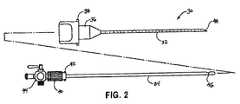
ここで、図面を詳細に参照すると、図1において観察されるように、半径方向に膨張可能な拡張アセンブリは、一般に、参照番号10を用いて示される。半径方向に膨張可能な拡張アセンブリ10は、管状シース12を備え、この管状シース12は、近位端14、遠位端16、およびその中を通って延びる軸方向管腔15を備える。軸方向管腔15は、長手方向軸「X」を規定し、さらに、その管腔の中を通って延びる第1断面積を規定する。近位端14は、近位方向にて半径方向外向きにテーパ状であり、そしてハンドル18に固定されている。ハンドル18は、その中を通って延びて管状シース12の管腔15に相互接続している、アパーチャ20を備える。管状シース12は、本明細書中で以後より詳細に記載される、シース12の半径方向膨張をもたらすために膨張アセンブリを受容可能である任意の材料から作製され得る。 Referring now in detail to the drawings, a radially inflatable expansion assembly is generally indicated using the
シース12は、好ましくは、同一人に譲渡された米国特許第5,431,676号に記載されるように、弾性膜により覆われた非弾性編み組(braid)を備える。この米国特許の全開示は、本明細書中に参考として援用される。適切な膨張可能なスリーブ10は、Tyco Healthcare,Ltd.の一部門であるUnited States Surgicalから、STEPTM導入器システムの一部として市販され得る。The
管状針32とスタイレット34とを備える気腹針アセンブリ30が、図2に示される。管状針32は、その近位端に、雄差し込みコネクタ38を備えるハブ36を備える。好ましくは、スタイレット34は、雄差し込み取付け具42を備える近位コネクタ40中にバネ装填されている。雄差し込み取付け具42は、ハブ36の雌差し込み取付け具(示さず)に、受容可能に結合されている。通気バルブ44が、スタイレット34の近位端に連結されており、入口46が、その遠位端に形成される。入口46は、バルブ44を通しての通気ガスの導入が、スタイレット34を通して放出されるのを可能にする。使用時に、スタイレット34は、ハブ36に取り付けられた差し込み取付け具42とともに針32内に取り付けられる。その後、スタイレット34の遠位端が針32の遠位端48から伸び、その結果、針アセンブリ30が、以下により詳細に記載されるように、組織と係合した時に、スタイレット34が針32の中に引き込まれる。 An
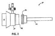
ここで、図3を参照すると、膨張アセンブリ50が示され、そして記載される。膨張アセンブリ50は、膨張部材52(すなわち、カニューレ管)および近位ハブ54を備える。膨張部材52は、その近位端にネジ付きコネクタ56を備え、このネジ付きコネクタは、近位ハブ54の遠位端において、取付け具58に取り外し可能に固定され得る。好ましくは、膨張部材52は、管状シース12の第1断面積よりも大きい第2断面積を規定する。 Referring now to FIG. 3, an
図4を参照すると、テーパ状遠位端74を有するシャフト72とハンドル76とを有する、閉塞具70が、示されそして記載される。以下により詳細に記載されるように、閉塞具70は、半径方向に膨張可能な拡張アセンブリ10の中への膨張アセンブリ50の挿入を容易にするために、カニューレアセンブリ50の中心管腔内に配置されることが、意図される。 Referring to FIG. 4, an
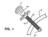
ここで図5を見ると、本開示に従う膨張アセンブリ挿入装置は、作動可能に取り付けられた膨張アセンブリ50および拡張アセンブリ10を備えており、参照番号100として一般に示される。挿入装置100は、近位に延びる固定ハンドル102、旋回ピン118にて固定ハンドル104に旋回可能に結合されたトリガー104、および遠位に延びるスピン部材106を備える。スピン部材106は、長手方向軸「X」を規定する、遠位端108および近位端110を有する。スピン部材106の近位端110は、固定ハンドル102の遠位端において形成されたアパーチャ102を通って、固定ハンドル102内にスライド可能に受容される。スピン部材106についてほぼ矩形の断面が示されているが、スピン部材106は、円形、楕円形、正方形、または他の多角形の断面を有し得ることが、企図される。 Turning now to FIG. 5, an expansion assembly insertion device in accordance with the present disclosure includes an
スピン部材106の遠位端108は、作動可能に結合されたヨークまたは係合特徴112を備える。ヨーク112は、一対のレッグ(leg)116、117を有する、U字型Uリンク(clevis)114を規定する。好ましくは、Uリンク114は、遠位の一対のレッグ116a、117aと、近位の一対のレッグ116b、117bとを備える。レッグ116、117は、スピン部材106の長手方向「X」軸と実質的に平行である軸を規定する。使用時に、ヨーク112のU字型Uリンク114は、その中に、拡張アセンブリ10のハンドル18を受容する。詳細には、ハンドル18は、一対の正反対に対向するタブ18a、18bを備え、ここで、タブ18aまたは18bのいずれかは、遠位レッグ116aと近位レッグ18bとの間に位置し、一方、タブ18aまたは18bのうちのもう一方は、遠位レッグ117aと近位レッグ117bとの間に位置する。 The distal end 108 of the
図6において最も良く観察されるように、固定ハンドル102は、挿入装置100の機械的操作のために作動機構を備える。この作動機構は、旋回点122にてトリガー104に旋回可能に結合された第1端120aと、固定ハンドル102内にスライド可能に受容されかつ駆動レバー130に旋回可能に結合された第2端120bとを有する、連結部材120を備える。 As best observed in FIG. 6, the fixed
駆動レバー130は、駆動レバー130中に形成されたアパーチャまたは開口部132を通る、スピン部材106上に位置付け、および/または懸架される。駆動レバー130と、固定ハンドル102の内部表面との間に配置された圧縮バネ134は、遠位方向に駆動レバー130を推進し、スピン部材106に対して直交するように保持する。バネ134の力は、トリガー104を、連結部材120を介して、固定ハンドル102のバッキング(backing)部材126に対して推進し、それにより、待機状態を提供する。この待機状態において、駆動レバー130は、作動時に矢印「P」により示されるスピン部材106の運動方向と実質的に垂直に位置する。旋回ピン118の周囲でのトリガー104の運動は、以下により詳細に記載されるように、スピン部材106がバネ134の付勢(bias)に対して移動することを引き起こす。 The
この作動機構は、スピン部材106が通る開口部138を有する、ブレーキングレバー136をさらに備える。ブレーキングレバー136の一端140は、固定ハンドル102中に形成された凹部142中に旋回可能に位置決めされ、その結果、ブレーキングレバー136は、凹部142の表面によって、およびブレーキングレバー136中の開口部138の縁がスピン部材106の表面と係合した場合にスピン部材106とのブレーキングレバー136の結合によって規定される、拘束内で旋回し得る。少なくとも1つの圧縮バネ144が、固定ハンドル102中の壁146とブレーキングレバー136との間に配置される。バネ144は、ブレーキングレバー136の自由端を、駆動レバー130から遠位へと、効果的に付勢する。付勢されたブレーキングレバー136の位置は、ブレーキングレバー136の開口部138とスピン部材106の表面との間の、結合および/またはコック(cock)の干渉により制限される。図6において示される実施形態において、ブレーキングレバー136は、固定ハンドル102の方向に延び、その結果、その遠位端148は、ユーザの親指によって適切に掴まれ得る。 The actuation mechanism further includes a braking lever 136 having an opening 138 through which the
図6において示される待機位置において、駆動レバー130は、スピン部材106の長手方向「X」軸と実質的に垂直であり、一方、スピン部材106と係合するブレーキングレバー136の一部は、スピン部材106の長手方向「X」に対してわずかな角度横向きであることが、留意されるべきである。この状態において、矢印「P」により示される方向にて、ヨーク112(図5)に対して力が付与された場合、スピン部材106は、固定ハンドル102を通って自由に移動する。ブレーキングレバー136は、矢印「P」により示される方向にて、ヨーク112に対して力が付与された場合には、バネ144の付勢に対して自由に旋回するので、ブレーキングレバー136は、スピン部材106およびヨーク112の運動に対して何ら障害を示さず、従って、固定ハンドル102を通って継続的に前進され得る。 In the standby position shown in FIG. 6, the
しかし、図6において示されるような待機位置において、矢印「P」により示される方向とは反対の方向にてヨーク112に力が付与された場合、ブレーキングレバー136中の開口部138の縁がスピン部材106の表面に結合し、そして、固定ハンドル102から離れるように移動するヨーク112を引き込むことは、可能ではない。ブレーキングレバー136を矢印「P」の方向に指で押すことによって、バネ144の圧縮は、スピン部材106およびヨーク112の引き込みが、固定ハンドル102から離れて伸びるようにすることが可能である。バネ144の圧縮は、ブレーキングレバー136の遠位端148を、スピン部材106の意図される運動方向と垂直にし、従って、スピン部材106は、ブレーキングレバー136中の開口部138を通るいずれかの方向で自由にスライドする。 However, in the standby position as shown in FIG. 6, when a force is applied to the
膨張アセンブリ挿入装置100の好ましい使用方法は、トリガー104を(固定ハンドル102に向かって)握り込んで、スピン部材106およびヨーク112を、固定ハンドル102を通して漸進的に前進させることである。トリガー104を握り込むと、旋回ピン118の周囲で旋回が生じ、連結部材120の第2端120bもまた、実質的に矢印「P」の方向に移動する。これは、駆動レバー130がその第1端131の周囲で旋回することを引き起こし、その結果、駆動レバー130は、もはや、スピン部材106の意図される運動方向「P」と垂直ではない。駆動レバー130の旋回は、バネ134を圧縮し、そしてまた、駆動レバー130中に形成されたアパーチャ132の端縁が、スピン部材106の表面に結合することを引き起こす。駆動レバー130は、スピン部材106の意図される運動方向「P」ともはや垂直ではないので、結合が生じる。トリガー104のさらなる運動は、駆動レバー130が矢印「P」の方向に平行移動することを引き起こす。この運動は、バネ134をさらに圧縮し、その過程において、駆動レバー130とスピン部材106との間の結合およびコック(cock)の干渉によって、固定ハンドル102を介してスピン部材106およびその結合したヨーク112を前進させる。トリガー104の1回の握り込みによるヨーク112の最大前進距離は、バネ134が完全に圧縮された場合またはトリガー104が固定ハンドル102の表面を打つ場合まで、制限される。 A preferred method of using the inflation
トリガー104が旋回ピン118の周囲で完全に旋回した後、トリガー104の解放は、バネ134に起因してトリガー104が待機状態まで戻り、駆動レバー130を垂直位置へと推進しそして連結部材120をトリガー104中へと押すことを引き起こす。 After the
図5に戻ると、固定ハンドル102は、その遠位端に固定された、少なくとも1つ(好ましくは一対)の弾力的なC字型カフ124をさらに備える。カフ124は、レッグ116、117によって規定されるUリンク114の軸に実質的に整列した、長手方向軸を規定する。使用時に、カフ124は、その中にカニューレアセンブリ50の近位ハブ54をスナップ留め(snap−fit)型係合により受容するような構成である。 Returning to FIG. 5, the fixed
さらに、固定ハンドル102は、上記のようなバッキング部材126を備える。バッキング部材126は、好ましくは、固定ハンドル102から、カフ124の長手方向軸を越えて横に延びる。従って、操作時に、好ましくは、膨張アセンブリ50が膨張アセンブリ挿入装置100に取り付けられた場合に、バッキング部材126は、膨張アセンブリ50の近位端表面に対する止め(stop)として作用する。 Further, the fixed
Uリンク114をカフ124に向けて漸進的に近接させるためのトリガー104を備える挿入装置100が、本明細書中で示されそして記載されてきたが、同じ機能を達成するために任意の操作部材が使用され得ることが、想定され、かつこのことは本開示の範囲内にある。例えば、その操作部材は、Uリンク114をカフ124に向かって前進させるために、つめ車(ratchet)機構、ネジ(screw)駆動、空気式(pneumatic)駆動などを備え得る。 Although the
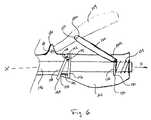
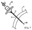
ここで、図7〜10を参照すると、膨張アセンブリ挿入装置100の好ましい操作方法が、記載される。まず、図7において観察されるように、気腹針アセンブリ30が挿入されている半径方向に膨張可能な拡張アセンブリ10が、針アセンブリ30の鋭利な遠位端48を患者の腹「A」の組織へと係合すること、そして拡張アセンブリ10の管状シース12が腹「A」の組織を通って伸びるまで、スリーブ/針の組合せを前進させることによって、患者の腹「A」(または他の身体位置)を通して導入される。 With reference now to FIGS. 7-10, a preferred method of operation of the inflation
その後、針アセンブリ30が取り除かれ、そして閉塞具70が中に配置された膨張アセンブリ50が、膨張アセンブリ挿入装置100の補助によって拡張アセンブリ10の管状シース12を通って導入され、そにより、管状シース12が半径方向に膨張する(図9参照)。詳細には、挿入装置100のヨーク112は、好ましくは、上記のような拡張アセンブリ10のハンドル18上に、まずひっかけられる(hooked)。次に、閉塞具70を備える膨張アセンブリ50が、膨張アセンブリ50の近位ハブ54を上記のようなカフ124に結合することによって、挿入装置100中に装填される。最後に、挿入装置100は、上記のようにトリガー104を繰返し握って、膨張アセンブリ50および閉塞具70を、拡張アセンブリ10を通して漸進的に前進させることによって、作動される。膨張アセンブリ50および閉塞具70が管状シース12を通って遠位に移動される場合、拡張アセンブリ10は、第1断面積から第2断面積へと半径方向に膨張される。 Thereafter, the
最後に、図10において示されるように、閉塞具70が膨張部材52から取り外され、腹壁「A」を通るアクセスチャネルが残る。このアクセスチャネルは、このアクセスチャネルを通って他の種々の外科器具を導入するためのものである。 Finally, as shown in FIG. 10,
挿入装置100の人間工学的特徴は、実質的に長手方向を向いた固定ハンドル102およびトリガー104である。換言すると、固定ハンドル102は、好ましくは、スピン部材106の長手方向軸と整列し、一方、トリガー104は、好ましくは、スピン部材106の長手方向軸と実質的に整列した閉鎖位置へと旋回可能である。従って、挿入装置100の長手方向軸は、外科医の前腕の長手方向軸に対して実質的に直行する方向を向いている。従って、外科医による挿入力の付与は、好ましくは、外科医が固定ハンドル102およびトリガー104を握ること、および外科医がその肘の周囲に前腕を旋回させることによって生じ、その結果、手が、挿入装置100の長手方向軸と実質的に同一線形順序に並んでいる(co−linear)方向で移動する。 The ergonomic features of the
ここで、図11に移ると、システム構成要素の種々の組合せを含む例示的パッケージまたは「キット」が、示される。このようなキットは、本開示のアクセスシステムを再構築するために必要な構成要素の在庫維持を容易にするための特に簡便な方法である。当然、完全なシステムがキット状態で販売され得ること、ならびに個別の構成要素各々が独立してキットの状態で販売され得ることが、認識される。多くの場合、1つのパッケージ中に構成要素対または複数の単一構成要素部品を一緒に組み合わせることが、特にその構成要素がたがいに適合する大きさである場合には、望ましい。これらのキットは、従来のパッケージ要素(代表的には、袋(pouch)、包装材料(envelope)、トレー(tray)、箱、発泡体挿入物(foam insert)、および外科器具の滅菌包装または非滅菌包装のために一般的に使用される型の他の容器)を備える。このパッケージはまた、代表的には、使用に関する指示、使用上の注意(warning)などを備えた書面の指示シートである、「パッケージ挿入物P」を備える。 Turning now to FIG. 11, an exemplary package or “kit” that includes various combinations of system components is shown. Such a kit is a particularly convenient way to facilitate inventory maintenance of the components necessary to reconstruct the access system of the present disclosure. Of course, it will be appreciated that the complete system can be sold in kit and that each individual component can be sold independently in kit. In many cases, it is desirable to combine component pairs or multiple single component parts together in one package, especially if the components are sized to fit each other. These kits can be used for conventional packaging elements (typically pouches, envelopes, trays, boxes, foam inserts, and sterile packaging or non-surgery of surgical instruments. Other containers of the type commonly used for sterile packaging. The package also typically includes a “package insert P”, which is a written instruction sheet with instructions for use, warnings, etc.
図11において観察されるように、標的外科部位へのアクセスを提供するための例示的キット200は、代表的には非滅菌のパッケージ202を備える。なぜなら、再利用可能な構成要素が、後に滅菌され得、それは、以下の品目のうちの少なくとも1つであり得るからである:半径方向に膨張可能な拡張アセンブリ10;気腹針アセンブリ30;スタイレット34;膨張アセンブリ50;および閉塞具70.キット200は、膨張アセンブリ挿入装置100をさらに備える。 As observed in FIG. 11, an
上記の開示は、明確さまたは理解のために、例示および例によって、いくらか詳細に記載されてきたが、特定の変化および改変が添付の特許請求の範囲内で実施され得ることが、明らかである。 Although the foregoing disclosure has been described in some detail by way of illustration and example for purposes of clarity or understanding, it will be apparent that certain changes and modifications may be practiced within the scope of the appended claims. .
(摘要)
経皮貫入を形成しそして拡大するための装置が、開示される。この装置は、
細長拡張部材であって、この細長拡張部材は、第1断面積を備えた半径方向に膨張可能な部材と;第1断面積よりも大きい第2断面積を有する管状要素を備える、細長膨張部材と;を備える。この装置は、前進装置をさらに備え、この前進装置は、
この拡張部材のハンドルと係合するための第1係合特徴を備える、第1アームと;
この膨張部材のハンドルと係合するための第2係合特徴を備える、第2アームと;
操作部材と;
を備える。この第1アームと第2アームとは、この操作部材を操作するとこの第1係合特徴とこの第2係合特徴とが共に接近するように連結されている。(Summary)
An apparatus for creating and expanding a percutaneous penetration is disclosed. This device
An elongate expansion member comprising a radially inflatable member having a first cross-sectional area; and a tubular element having a second cross-sectional area greater than the first cross-sectional area. And comprising; The apparatus further comprises an advance device, the advance device comprising:
A first arm with a first engagement feature for engaging the handle of the expansion member;
A second arm with a second engagement feature for engaging the handle of the expansion member;
An operation member;
Is provided. The first arm and the second arm are connected so that the first engagement feature and the second engagement feature come close together when the operation member is operated.
添付の図面は、本明細書の一部に組み込まれ、かつ本明細書の一部を構成する。添付の図面は、本開示の実施形態を示し、上記に示された実施形態の詳細な説明とともに、本開示の原理を説明するために役立つ。
Claims (15)
Translated fromJapanese細長拡張部材であって、該細長拡張部材は、半径方向に膨張可能な部材を備え、該半径方向に膨張可能な部材は、ハンドルを備えた近位端と、遠位端と、第1断面積を備えた軸方向管腔とを備え、該ハンドルは、一対の正反対に対向するタブを備えている、細長拡張部材;
細長膨張部材であって、該細長膨張部材は、管状部材を備え、該管状部材は、遠位端と、ハンドルを備えた近位端と、該第1断面積よりも大きい第2断面積を備えた軸方向管腔とを備え、該細長膨張部材の遠位端は、該拡張部材の軸方向管腔を通しての該管状部材の挿入を容易にするための構成である、細長膨張部材;
前進装置であって、該前進装置は、
一対の遠位レッグと一対の近位レッグとを備えるU字型Uリンクによって規定される第1係合特徴を備える、第1アームであって、該第1係合特徴は、該拡張部材の該第1アームに対する軸方向の移動を阻害するように該拡張部材のハンドルと係合し、該拡張部材のハンドルは、該Uリンクの該遠位レッグと該近位レッグとの間に該タブを配置することによって係合される、第1アームと;
該Uリンクの該アームに整列した長手方向軸を規定する一対の弾力的なC字型カフによって規定される第2係合特徴を備える、第2アームであって、該第2係合特徴は、該膨張部材の該第2アームに対する軸方向の移動を阻害するように該膨張部材のハンドルと係合し、該管状部材の該近位端は、スナップ留め型係合で該カフによって受容される、第2アームと;
操作部材と;
を備え、該第1アームと該第2アームとは、該拡張部材と該膨張部材との間の軸方向の整列を維持するように構成されており、そして、該第1アームと該第2アームとは、該操作部材を操作すると該第1係合特徴と該第2係合特徴とが共に接近するように連結されている、前進装置;
を備える、装置。A device for forming and enlarging a percutaneous penetration, the device comprising:
An elongate expansion member, the elongate expansion member comprising a radially inflatable member, the radially inflatable member comprising a proximal end with a handle, a distal end, and a first disconnection. An elongated lumen having an axial lumen with an area, the handle comprising a pair of diametrically opposed tabs;
An elongate inflatable member, the elongate inflatable member comprising a tubular member, the tubular member having a distal end, a proximal end with a handle, and a second cross-sectional area greater than the first cross-sectional area. An elongated inflation member, wherein the distal end of the elongated inflation member is configured to facilitate insertion of the tubular member through the axial lumen of the expansion member;
An advancement device, the advancement device comprising:
A first arm comprising a first engagement feature defined by a U-shaped U-link comprising a pair of distal legs and a pair of proximal legs, the first engagement feature comprising: Engaging the handle of the expansion member to impede axial movement relative to the first arm, the handle of the expansion member being connected between the distal leg and the proximal leg of the U-link A first arm engaged by positioning;
A second arm comprising a second engagement feature defined by a pair of resilient C-shaped cuffs defining a longitudinal axis aligned with the arm of the U-link, wherein the second engagement feature is Engaging the expansion member handle to inhibit axial movement of the expansion member relative to the second arm, the proximal end of the tubular member being received by the cuff in a snap-fit engagement. A second arm;
An operation member;
The first arm and the second arm are configured to maintain axial alignment between the expansion member and the expansion member, and the first arm and the second arm An advance device in which the arm is connected so that the first engagement feature and the second engagement feature are close together when the operation member is operated;
An apparatus comprising:
細長拡張部材であって、該細長拡張部材は、半径方向に膨張可能な部材を備え、該半径方向に膨張可能な部材は、ハンドルを備えた近位端と、遠位端と、第1断面積を備えた軸方向管腔とを備え、該ハンドルは、一対の正反対に対向するタブを備えている、細長拡張部材;
細長膨張部材であって、該細長膨張部材は、管状部材を備え、該管状部材は、遠位端と、ハンドルを備えた近位端と、該第1断面積よりも大きい第2断面積を備えた軸方向管腔とを備え、該細長膨張部材の遠位端は、該拡張部材の軸方向管腔を通しての該管状部材の挿入を容易にするための構成である、細長膨張部材;
前進装置であって、該前進装置は、
一対の遠位レッグと一対の近位レッグとを備えるU字型Uリンクによって規定される第1係合特徴を備える、第1アームであって、該第1係合特徴は、該拡張部材の該第1アームに対する軸方向の移動を阻害するように該拡張部材のハンドルと係合し、該拡張部材のハンドルは、該Uリンクの該遠位レッグと該近位レッグとの間に該タブを配置することによって係合される、第1アームと;
該第1アームを受容するための通路と、該Uリンクの該アームに整列した長手方向軸を規定する一対の弾力的なC字型カフによって規定される第2係合特徴とを備える、第2アームであって、該第2係合特徴は、該膨張部材のハンドルと係合し、該管状部材の該近位端は、スナップ留め型係合で該カフによって受容される、第2アームと;
該第2アームに旋回可能に連結された操作部材であって、該操作部材は、該第1アームと係合する旋回リンクを備え、該操作部材を押すと、該旋回リンクが該第1アームを近位方向に移動させるようになっている、操作部材と;
を備え、該第1アームと該第2アームとは、該操作部材を操作すると該第1係合特徴と該第2係合特徴とが共に接近するように連結されている、前進装置;
を備える、装置。A device for forming and enlarging a percutaneous penetration, the device comprising:
An elongate expansion member, the elongate expansion member comprising a radially inflatable member, the radially inflatable member comprising a proximal end with a handle, a distal end, and a first disconnection. An elongated lumen having an axial lumen with an area, the handle comprising a pair of diametrically opposed tabs;
An elongate inflatable member, the elongate inflatable member comprising a tubular member, the tubular member having a distal end, a proximal end with a handle, and a second cross-sectional area greater than the first cross-sectional area. An elongated inflation member, wherein the distal end of the elongated inflation member is configured to facilitate insertion of the tubular member through the axial lumen of the expansion member;
An advancement device, the advancement device comprising:
A first arm comprising a first engagement feature defined by a U-shaped U-link comprising a pair of distal legs and a pair of proximal legs, the first engagement feature comprising: Engaging the handle of the expansion member to impede axial movement relative to the first arm, the handle of the expansion member being connected between the distal leg and the proximal leg of the U-link A first arm engaged by positioning;
A passageway for receiving the first arm and a second engagement feature defined by a pair of resilient C-shaped cuffs defining a longitudinal axis aligned with the arm of the U-link. A second arm, wherein the second engagement feature engages the handle of the expansion member and the proximal end of the tubular member is received by the cuff in a snap-fit engagement When;
An operation member that is pivotably connected to the second arm, the operation member including a pivot link that engages with the first arm, and when the manipulation member is pushed, the pivot link is moved to the first arm. An operating member adapted to move proximally in the proximal direction;
An advancement device, wherein the first arm and the second arm are coupled such that the first engagement feature and the second engagement feature are close together when the operation member is operated;
An apparatus comprising:
Applications Claiming Priority (2)
| Application Number | Priority Date | Filing Date | Title |
|---|---|---|---|
| US50450603P | 2003-09-19 | 2003-09-19 | |
| US60/504,506 | 2003-09-19 |
Related Child Applications (2)
| Application Number | Title | Priority Date | Filing Date |
|---|---|---|---|
| JP2010160148ADivisionJP2010279709A (en) | 2003-09-19 | 2010-07-14 | Trocar insertion apparatus |
| JP2010160149ADivisionJP2010279710A (en) | 2003-09-19 | 2010-07-14 | Trocar insertion apparatus |
Publications (2)
| Publication Number | Publication Date |
|---|---|
| JP2005087744A JP2005087744A (en) | 2005-04-07 |
| JP5025899B2true JP5025899B2 (en) | 2012-09-12 |
Family
ID=34193394
Family Applications (3)
| Application Number | Title | Priority Date | Filing Date |
|---|---|---|---|
| JP2004274252AExpired - Fee RelatedJP5025899B2 (en) | 2003-09-19 | 2004-09-21 | Trocar insertion device |
| JP2010160148AWithdrawnJP2010279709A (en) | 2003-09-19 | 2010-07-14 | Trocar insertion apparatus |
| JP2010160149AWithdrawnJP2010279710A (en) | 2003-09-19 | 2010-07-14 | Trocar insertion apparatus |
Family Applications After (2)
| Application Number | Title | Priority Date | Filing Date |
|---|---|---|---|
| JP2010160148AWithdrawnJP2010279709A (en) | 2003-09-19 | 2010-07-14 | Trocar insertion apparatus |
| JP2010160149AWithdrawnJP2010279710A (en) | 2003-09-19 | 2010-07-14 | Trocar insertion apparatus |
Country Status (7)
| Country | Link |
|---|---|
| US (2) | US7479150B2 (en) |
| EP (1) | EP1516592B1 (en) |
| JP (3) | JP5025899B2 (en) |
| AU (1) | AU2004212570B2 (en) |
| CA (1) | CA2481967C (en) |
| DE (1) | DE602004005116T2 (en) |
| ES (1) | ES2279270T3 (en) |
Families Citing this family (30)
| Publication number | Priority date | Publication date | Assignee | Title |
|---|---|---|---|---|
| US20090132021A1 (en)* | 2005-02-01 | 2009-05-21 | Shifrin Edward G | Apparatus and method for delivery, spreading and double-ended fixation of vascular grafts |
| US8795235B2 (en)* | 2006-10-06 | 2014-08-05 | Surgiquest, Inc. | Devices for and methods of performing minimally-invasive surgical procedures through a single incision |
| US8372131B2 (en)* | 2007-07-16 | 2013-02-12 | Power Ten , LLC | Surgical site access system and deployment device for same |
| US20090024158A1 (en)* | 2007-07-16 | 2009-01-22 | Zimmer Spine, Inc. | Access Port Expander And Method |
| US20090082731A1 (en)* | 2007-09-20 | 2009-03-26 | Ethicon Endo-Surgery, Inc. | Dilating trocar cannula |
| WO2010064062A1 (en)* | 2008-04-08 | 2010-06-10 | A.S.S.O. Hospital S.N.C. | Guiding device for ophthalmic mininvasive surgery |
| US20090264709A1 (en) | 2008-04-21 | 2009-10-22 | Plexus Biomedical, Inc. | Method and Apparatus for Retention of Adipose Tissue |
| DE102009060377B4 (en)* | 2009-12-24 | 2016-10-20 | Richard Wolf Gmbh | trocar |
| AU2011237339B2 (en)* | 2010-04-08 | 2014-10-30 | BiO2 Medical, Inc. | Catheter hub |
| US9918723B2 (en)* | 2011-09-23 | 2018-03-20 | Depuy Mitek, Llc | Glenoid anchor guide |
| KR20140087032A (en)* | 2011-10-31 | 2014-07-08 | 유타카 스즈키 | Medical dilating instrument and medical dilating instrument set |
| EP2695581B1 (en) | 2012-08-07 | 2019-03-13 | Critical Innovations, LLC | Device for simultaneously documenting and treating tension pneumothorax and/or hemothorax |
| US8597306B1 (en) | 2013-03-14 | 2013-12-03 | Plexus Biomedical, Inc. | Labor management methods for decreasing the incidence of cesarean childbirth |
| EP2986233B1 (en) | 2013-04-16 | 2022-06-15 | Teleflex Medical Incorporated | Needlescopic instrument with reusable handle and detachable needle assembly |
| DE102013104789A1 (en)* | 2013-05-08 | 2014-11-13 | Karl Storz Gmbh & Co. Kg | Dilatation device and expandable cover for a dilatation instrument |
| CA2924097C (en) | 2013-09-18 | 2018-03-06 | Teleflex Medical Incorporated | Exchanger surgical access port assembly |
| US10046147B2 (en) | 2013-12-26 | 2018-08-14 | Critical Innovations, LLC | Percutaneous access pathway system and method |
| EP3142541A4 (en)* | 2014-05-13 | 2017-04-26 | Vycor Medical, Inc. | Guidance system mounts for surgical introducers |
| EP3071131B1 (en) | 2014-07-15 | 2019-02-27 | Teleflex Medical Incorporated | Exchanger surgical access port assembly |
| US10080520B2 (en) | 2015-02-27 | 2018-09-25 | Stetrix, Inc. | Labor monitoring of pelvic floor |
| AU2017235583A1 (en)* | 2016-03-18 | 2018-10-04 | The Feinstein Institute For Medical Research | Introducer and methods of use thereof |
| US10543016B2 (en) | 2016-11-07 | 2020-01-28 | Vycor Medical, Inc. | Surgical introducer with guidance system receptacle |
| US12178469B2 (en) | 2016-11-07 | 2024-12-31 | Vycor Medical Inc. | Surgical introducer with guidance system receptacle |
| US10376258B2 (en) | 2016-11-07 | 2019-08-13 | Vycor Medical, Inc. | Surgical introducer with guidance system receptacle |
| US9993382B1 (en) | 2017-07-10 | 2018-06-12 | Stetrix, Inc. | Tissue retention systems and methods |
| US10814119B2 (en) | 2017-09-22 | 2020-10-27 | Critical Innovations, LLC | Percutaneous access pathway system |
| CN110856664B (en)* | 2018-08-23 | 2022-03-25 | 武汉联影智融医疗科技有限公司 | Surgical robot and puncture mechanism thereof |
| US10856907B2 (en) | 2018-02-21 | 2020-12-08 | Charles P. Virden | Atraumatic trocar medication delivery method |
| US11406806B2 (en)* | 2018-02-21 | 2022-08-09 | Charles P. Virden | Atraumatic trocar apparatus, system and kit |
| EP4432940A1 (en)* | 2021-11-15 | 2024-09-25 | CONMED Corporation | Access ports for use with surgical robots |
Family Cites Families (149)
| Publication number | Priority date | Publication date | Assignee | Title |
|---|---|---|---|---|
| US219296A (en) | 1879-09-02 | Improvement in machines for slicing logs into strips | ||
| US319296A (en) | 1885-06-02 | Peters | ||
| US668879A (en) | 1900-07-19 | 1901-02-26 | Wilber L Miller | Vein-dilator for embalmers' use. |
| US702789A (en) | 1902-03-20 | 1902-06-17 | Charles Gordon Gibson | Dilator. |
| US1213001A (en) | 1916-05-02 | 1917-01-16 | Ralph S Philips | Therapeutic apparatus. |
| US1248492A (en) | 1917-04-10 | 1917-12-04 | A D Haskell | Paracentesis needle or trocar. |
| US2548602A (en) | 1948-04-09 | 1951-04-10 | Greenburg Leonard | Inflatable dilator |
| US2566499A (en) | 1950-02-14 | 1951-09-04 | Richter Bruno | Expansile surgical needle |
| US3509883A (en) | 1967-11-29 | 1970-05-05 | Gen Electric | Expanding cannula |
| US3545443A (en) | 1968-09-26 | 1970-12-08 | Amir H Ansari | Suprapubic cystostomy needle |
| US3742958A (en) | 1971-04-21 | 1973-07-03 | C Rundles | Suprapubic catheter inserter |
| US3811449A (en) | 1972-03-08 | 1974-05-21 | Becton Dickinson Co | Dilating apparatus and method |
| US3789852A (en) | 1972-06-12 | 1974-02-05 | S Kim | Expandable trochar, especially for medical purposes |
| US3788318A (en) | 1972-06-12 | 1974-01-29 | S Kim | Expandable cannular, especially for medical purposes |
| GB1443828A (en) | 1973-05-14 | 1976-07-28 | Greenhalgh R M | Catheters |
| JPS5239596B2 (en) | 1974-04-04 | 1977-10-06 | ||
| US3968800A (en) | 1974-09-17 | 1976-07-13 | Vilasi Joseph A | Device for insertion into a body opening |
| US4320762A (en) | 1975-03-10 | 1982-03-23 | Bentov Itzhak E | Dilator |
| US4141364A (en) | 1977-03-18 | 1979-02-27 | Jorge Schultze | Expandable endotracheal or urethral tube |
| US4461281A (en) | 1977-06-15 | 1984-07-24 | Carson Robert W | Arthroscopic surgical apparatus and method |
| US4183102A (en) | 1977-09-08 | 1980-01-15 | Jacques Guiset | Inflatable prosthetic device for lining a body duct |
| US4630609A (en) | 1981-05-14 | 1986-12-23 | Thomas J. Fogarty | Dilatation catheter method and apparatus |
| DE8132839U1 (en) | 1981-11-10 | 1982-03-11 | B. Braun Melsungen Ag, 3508 Melsungen | REINFORCING CORE FOR A CATHETER TUBE |
| US4411655A (en) | 1981-11-30 | 1983-10-25 | Schreck David M | Apparatus and method for percutaneous catheterization |
| SE445884B (en) | 1982-04-30 | 1986-07-28 | Medinvent Sa | DEVICE FOR IMPLANTATION OF A RODFORM PROTECTION |
| US4447237A (en) | 1982-05-07 | 1984-05-08 | Dow Corning Corporation | Valving slit construction and cooperating assembly for penetrating the same |
| US4493701A (en) | 1982-08-19 | 1985-01-15 | American Hospital Supply Corporation | Wound drainage device of resilient sidewalls with a constant rate of recovery |
| US4479497A (en) | 1982-11-12 | 1984-10-30 | Thomas J. Fogarty | Double lumen dilatation catheter |
| US4610688A (en) | 1983-04-04 | 1986-09-09 | Pfizer Hospital Products Group, Inc. | Triaxially-braided fabric prosthesis |
| US4753636A (en) | 1983-08-02 | 1988-06-28 | Endocon, Inc. | Subcutaneous implant kit |
| US4601710B1 (en)* | 1983-08-24 | 1998-05-05 | United States Surgical Corp | Trocar assembly |
| US4774091A (en) | 1983-10-14 | 1988-09-27 | Sumitomo Pharmaceuticals Company, Ltd. | Long-term sustained-release preparation |
| US4581025A (en) | 1983-11-14 | 1986-04-08 | Cook Incorporated | Sheath |
| US4589868A (en) | 1984-03-12 | 1986-05-20 | Dretler Stephen P | Expandable dilator-catheter |
| GB8424436D0 (en) | 1984-09-27 | 1984-10-31 | Pratt Int Ltd Burnerd | Surgical appliance |
| GB8513702D0 (en) | 1985-05-30 | 1985-07-03 | Gill S S | Expansible trocar |
| US4601713A (en) | 1985-06-11 | 1986-07-22 | Genus Catheter Technologies, Inc. | Variable diameter catheter |
| US4738666A (en) | 1985-06-11 | 1988-04-19 | Genus Catheter Technologies, Inc. | Variable diameter catheter |
| US4706670A (en) | 1985-11-26 | 1987-11-17 | Meadox Surgimed A/S | Dilatation catheter |
| US4610668A (en)* | 1985-10-02 | 1986-09-09 | Fleig John A | Preselected multiple dosage syringe |
| US4650466A (en) | 1985-11-01 | 1987-03-17 | Angiobrade Partners | Angioplasty device |
| US4733665C2 (en) | 1985-11-07 | 2002-01-29 | Expandable Grafts Partnership | Expandable intraluminal graft and method and apparatus for implanting an expandable intraluminal graft |
| US4654030A (en)* | 1986-02-24 | 1987-03-31 | Endotherapeutics | Trocar |
| US4719825A (en)* | 1986-03-24 | 1988-01-19 | Lahaye Peter G | Metering needle assembly |
| GB2199247B (en) | 1986-11-29 | 1990-06-20 | Femcare Ltd | Improvements in or relating to subcutaneous implantation equipment |
| JPS63158064A (en) | 1986-12-23 | 1988-07-01 | テルモ株式会社 | Blood vessel dilating catheter |
| US4772266A (en) | 1987-05-04 | 1988-09-20 | Catheter Technology Corp. | Catheter dilator/sheath assembly and method |
| US4798193A (en) | 1987-05-18 | 1989-01-17 | Thomas J. Fogarty | Protective sheath instrument carrier |
| GB2205751A (en) | 1987-06-04 | 1988-12-21 | Femcare Ltd | Insertion of catheters |
| JPS642662A (en) | 1987-06-25 | 1989-01-06 | Nippon Sherwood Kk | Easy split plastic cannula excellent in stability |
| DE3802158A1 (en) | 1987-08-11 | 1989-02-23 | Hoechst Ag | DEVICE FOR APPLICATION OF IMPLANTS |
| US4921479A (en) | 1987-10-02 | 1990-05-01 | Joseph Grayzel | Catheter sheath with longitudinal seam |
| US4931042A (en)* | 1987-10-26 | 1990-06-05 | Endotherapeutics | Trocar assembly with improved latch |
| US5487739A (en) | 1987-11-17 | 1996-01-30 | Brown University Research Foundation | Implantable therapy systems and methods |
| FR2624747A1 (en) | 1987-12-18 | 1989-06-23 | Delsanti Gerard | REMOVABLE ENDO-ARTERIAL DEVICES FOR REPAIRING ARTERIAL WALL DECOLLEMENTS |
| US4846812A (en) | 1988-03-22 | 1989-07-11 | Menlo Care, Inc. | Softening catheter |
| US4869717A (en) | 1988-04-25 | 1989-09-26 | Adair Edwin Lloyd | Gas insufflation needle with instrument port |
| US5556376A (en) | 1988-07-22 | 1996-09-17 | Yoon; Inbae | Multifunctional devices having loop configured portions and collection systems for endoscopic surgical procedures and methods thereof |
| US4896669A (en) | 1988-08-31 | 1990-01-30 | Meadox Medicals, Inc. | Dilatation catheter |
| US4846791A (en) | 1988-09-02 | 1989-07-11 | Advanced Medical Technology & Development Corp. | Multi-lumen catheter |
| US4985022A (en) | 1988-11-23 | 1991-01-15 | Med Institute, Inc. | Catheter having durable and flexible segments |
| US4972827A (en) | 1989-02-06 | 1990-11-27 | Fuji Photo Optical Co., Ltd. | Guide device for percutaneous insertion of endoscope |
| US4996583A (en) | 1989-02-15 | 1991-02-26 | Matsushita Electric Industrial Co., Ltd. | Stack type semiconductor package |
| EP0385920A3 (en) | 1989-03-03 | 1991-10-09 | Thomas J. Fogarty | Variable diameter sheath apparatus for use in body passages |
| US5234425A (en) | 1989-03-03 | 1993-08-10 | Thomas J. Fogarty | Variable diameter sheath method and apparatus for use in body passages |
| US5112304A (en) | 1989-03-17 | 1992-05-12 | Angeion Corporation | Balloon catheter |
| US5116318A (en) | 1989-06-06 | 1992-05-26 | Cordis Corporation | Dilatation balloon within an elastic sleeve |
| US5535755A (en)* | 1989-07-22 | 1996-07-16 | Heske; Norbert | Tissue sampler |
| US5009643A (en)* | 1989-08-09 | 1991-04-23 | Richard Wolf Medical Instruments Corp. | Self-retaining electrically insulative trocar sleeve and trocar |
| US5100388A (en) | 1989-09-15 | 1992-03-31 | Interventional Thermodynamics, Inc. | Method and device for thermal ablation of hollow body organs |
| US5045056A (en) | 1989-09-15 | 1991-09-03 | Behl Robert S | Method and device for thermal ablation of hollow body organs |
| US5222938A (en) | 1989-09-15 | 1993-06-29 | Interventional Thermodynamics, Inc. | Method for thermal ablation of hollow body organs |
| US4986830A (en) | 1989-09-22 | 1991-01-22 | Schneider (U.S.A.) Inc. | Valvuloplasty catheter with balloon which remains stable during inflation |
| US5122122A (en) | 1989-11-22 | 1992-06-16 | Dexide, Incorporated | Locking trocar sleeve |
| US5041093A (en) | 1990-01-31 | 1991-08-20 | Boston Scientific Corp. | Catheter with foraminous anchor |
| GB2240718A (en) | 1990-02-09 | 1991-08-14 | Hundon Forge Ltd | Implanting device with needle cover |
| GB2240926A (en) | 1990-02-14 | 1991-08-21 | Steven Streatfield Gill | An expansible cannula |
| US5197971A (en) | 1990-03-02 | 1993-03-30 | Bonutti Peter M | Arthroscopic retractor and method of using the same |
| US5226899A (en) | 1990-03-26 | 1993-07-13 | Becton, Dickinson And Company | Catheter tubing of controlled in vivo softening |
| US5201756A (en) | 1990-06-20 | 1993-04-13 | Danforth Biomedical, Inc. | Radially-expandable tubular elements for use in the construction of medical devices |
| US5188602A (en) | 1990-07-12 | 1993-02-23 | Interventional Thermodynamics, Inc. | Method and device for delivering heat to hollow body organs |
| US5250025A (en) | 1990-08-15 | 1993-10-05 | Intramed Laboratories | Percutaneous access catheter and method of use |
| US5391183A (en) | 1990-09-21 | 1995-02-21 | Datascope Investment Corp | Device and method sealing puncture wounds |
| US5222971A (en) | 1990-10-09 | 1993-06-29 | Scimed Life Systems, Inc. | Temporary stent and methods for use and manufacture |
| US5147316A (en)* | 1990-11-19 | 1992-09-15 | Castillenti Thomas A | Laparoscopic trocar with self-locking port sleeve |
| DE69123982T2 (en) | 1990-11-20 | 1997-12-04 | Innerdyne Medical Inc | STRETCH MAINTENANCE GUIDE ELEMENT AND DILATATOR |
| US5350393A (en)* | 1992-01-06 | 1994-09-27 | Inbae Yoon | Safety trocar penetrating instrument |
| US6325789B1 (en) | 1990-12-27 | 2001-12-04 | Datascope Investment Corporation | Device and method for sealing puncture wounds |
| US5230702A (en) | 1991-01-16 | 1993-07-27 | Paradigm Biotechnologies Partnership | Hemodialysis method |
| US5115816A (en)* | 1991-01-24 | 1992-05-26 | Peter F. Lee, Inc. | Single-hand controlled fine needle aspiration device |
| US5144942A (en)* | 1991-03-21 | 1992-09-08 | United States Surgical Corporation | Endoscopic instrumentation kit and package therefor |
| US5158545A (en) | 1991-05-02 | 1992-10-27 | Brigham And Women's Hospital | Diameter expansion cannula |
| US5244619A (en) | 1991-05-03 | 1993-09-14 | Burnham Warren R | Method of making catheter with irregular inner and/or outer surfaces to reduce travelling friction |
| WO1992020290A1 (en) | 1991-05-17 | 1992-11-26 | Innerdyne Medical, Inc. | Method and device for thermal ablation |
| US5183464A (en) | 1991-05-17 | 1993-02-02 | Interventional Thermodynamics, Inc. | Radially expandable dilator |
| US5542928A (en) | 1991-05-17 | 1996-08-06 | Innerdyne, Inc. | Method and device for thermal ablation having improved heat transfer |
| WO1992020400A1 (en) | 1991-05-24 | 1992-11-26 | Sumitomo Pharmaceuticals Company, Limited | Instrument for applying pharmaceutical to inside of brain |
| US5935122A (en) | 1991-12-13 | 1999-08-10 | Endovascular Technologies, Inc. | Dual valve, flexible expandable sheath and method |
| US5458579A (en)* | 1991-12-31 | 1995-10-17 | Technalytics, Inc. | Mechanical trocar insertion apparatus |
| US5246424A (en) | 1992-03-13 | 1993-09-21 | Wilk Peter J | Device and method for use in obtaining access to an internal body organ |
| US5403278A (en) | 1992-04-15 | 1995-04-04 | Datascope Investment Corp. | Device and method for treating hematomas and false aneurysms |
| US5380290A (en) | 1992-04-16 | 1995-01-10 | Pfizer Hospital Products Group, Inc. | Body access device |
| US5312417A (en) | 1992-07-29 | 1994-05-17 | Wilk Peter J | Laparoscopic cannula assembly and associated method |
| US6090072A (en) | 1992-10-15 | 2000-07-18 | Scimed Life Systems, Inc. | Expandable introducer sheath |
| US5250033A (en) | 1992-10-28 | 1993-10-05 | Interventional Thermodynamics, Inc. | Peel-away introducer sheath having proximal fitting |
| US5409498A (en)* | 1992-11-05 | 1995-04-25 | Ethicon, Inc. | Rotatable articulating endoscopic fastening instrument |
| US5316360A (en) | 1993-01-05 | 1994-05-31 | Feikema Orville A | Automobile sun visor |
| US5320611A (en) | 1993-02-04 | 1994-06-14 | Peter M. Bonutti | Expandable cannula having longitudinal wire and method of use |
| US6338730B1 (en) | 1993-02-04 | 2002-01-15 | Peter M. Bonutti | Method of using expandable cannula |
| US5674240A (en) | 1993-02-04 | 1997-10-07 | Peter M. Bonutti | Expandable cannula |
| US5961499A (en) | 1993-02-04 | 1999-10-05 | Peter M. Bonutti | Expandable cannula |
| US5431676A (en) | 1993-03-05 | 1995-07-11 | Innerdyne Medical, Inc. | Trocar system having expandable port |
| US5814058A (en) | 1993-03-05 | 1998-09-29 | Innerdyne, Inc. | Method and apparatus employing conformable sleeve for providing percutaneous access |
| US5304119A (en) | 1993-06-24 | 1994-04-19 | Monsanto Company | Instrument for injecting implants through animal hide |
| US5453094A (en)* | 1993-09-17 | 1995-09-26 | Minnesota Mining And Manufacturing Company | Kit assembly for use during a laparoscopic surgical procedure |
| US5392766A (en) | 1993-10-06 | 1995-02-28 | Innerdyne Medical, Inc. | System and method for cleaning viewing scope lenses |
| US5407430A (en) | 1994-03-21 | 1995-04-18 | Peters; Michael J. | Intravenous catheter |
| US5526822A (en)* | 1994-03-24 | 1996-06-18 | Biopsys Medical, Inc. | Method and apparatus for automated biopsy and collection of soft tissue |
| US5484403A (en) | 1994-04-05 | 1996-01-16 | Avid Marketing, Inc. | Hypodermic syringe for implanting solid objects |
| WO1995030374A1 (en) | 1994-05-06 | 1995-11-16 | Origin Medsystems, Inc. | Apparatus and method for delivering a patch |
| US5454790A (en) | 1994-05-09 | 1995-10-03 | Innerdyne, Inc. | Method and apparatus for catheterization access |
| JP3970341B2 (en) | 1994-06-20 | 2007-09-05 | テルモ株式会社 | Vascular catheter |
| US5540658A (en) | 1994-06-27 | 1996-07-30 | Innerdyne, Inc. | Transcervical uterine access and sealing device |
| US5460170A (en) | 1994-08-23 | 1995-10-24 | Hammerslag; Julius G. | Adjustable surgical retractor |
| US5885217A (en) | 1995-01-20 | 1999-03-23 | Tyco Group S.A.R.L. | Catheter introducer |
| US5938645A (en) | 1995-05-24 | 1999-08-17 | Boston Scientific Corporation Northwest Technology Center Inc. | Percutaneous aspiration catheter system |
| US5766201A (en) | 1995-06-07 | 1998-06-16 | Boston Scientific Corporation | Expandable catheter |
| US5938587A (en) | 1996-04-25 | 1999-08-17 | Modified Polymer Components, Inc. | Flexible inner liner for the working channel of an endoscope |
| US5713867A (en) | 1996-04-29 | 1998-02-03 | Medtronic, Inc. | Introducer system having kink resistant splittable sheath |
| US5827319A (en) | 1996-05-20 | 1998-10-27 | Innerdyne, Inc. | Radially expandable access system having disposable and reusable components |
| WO1998019730A1 (en) | 1996-11-04 | 1998-05-14 | Sherwood Medical Company | Coated radially expandable dilator for use with gastrointestinal-type tubes |
| WO1998029026A2 (en) | 1996-12-30 | 1998-07-09 | Imagyn Medical Technologies, Inc. | Expandable access device and method of constructing and using same |
| US5836913A (en) | 1997-05-02 | 1998-11-17 | Innerdyne, Inc. | Device and method for accessing a body cavity |
| US6331166B1 (en)* | 1998-03-03 | 2001-12-18 | Senorx, Inc. | Breast biopsy system and method |
| US6261241B1 (en)* | 1998-03-03 | 2001-07-17 | Senorx, Inc. | Electrosurgical biopsy device and method |
| US6875182B2 (en)* | 1998-03-03 | 2005-04-05 | Senorx, Inc. | Electrosurgical specimen-collection system |
| US6095967A (en) | 1998-03-25 | 2000-08-01 | Manan Medical Products, Inc. | Isotope seeding system that releases radioactive seeds for treatment of cancerous cells |
| US6450989B2 (en) | 1998-04-27 | 2002-09-17 | Artemis Medical, Inc. | Dilating and support apparatus with disease inhibitors and methods for use |
| US6245052B1 (en)* | 1998-07-08 | 2001-06-12 | Innerdyne, Inc. | Methods, systems, and kits for implanting articles |
| US6280417B1 (en)* | 1999-02-23 | 2001-08-28 | Needberg Technologies, Inc. | Trocar |
| US6428550B1 (en) | 1999-05-18 | 2002-08-06 | Cardica, Inc. | Sutureless closure and deployment system for connecting blood vessels |
| EP1194074A4 (en) | 1999-05-19 | 2002-09-11 | Innerdyne Medical Inc | SYSTEM AND METHOD TO ENABLE VASCULAR ACCESS |
| US7083618B2 (en)* | 2001-04-06 | 2006-08-01 | Sherwood Services Ag | Vessel sealer and divider |
| US7189249B2 (en)* | 2001-05-11 | 2007-03-13 | Applied Medical Resources Corporation | Traction trocar apparatus and method |
| EP1418850B1 (en) | 2001-08-01 | 2010-10-06 | Tyco Healthcare Group LP | Apparatus for providing percutaneous access and medicament to a target surgical site |
| US6605098B2 (en)* | 2001-09-28 | 2003-08-12 | Ethicon, Inc. | Surgical device for creating an anastomosis between first and second hollow organs |
| US7022085B2 (en)* | 2002-11-20 | 2006-04-04 | Scimed Life Systems, Inc. | Medical instrument |
| US7217275B2 (en)* | 2003-01-14 | 2007-05-15 | Crabtree John H | Tunnel port apparatus with serial gas-check assembly |
| US7329227B2 (en)* | 2004-10-21 | 2008-02-12 | Inter-V-Manan | Forward-fired automatic tissue sampling apparatus with safety lock |
- 2004
- 2004-09-16USUS10/943,132patent/US7479150B2/ennot_activeExpired - Fee Related
- 2004-09-17AUAU2004212570Apatent/AU2004212570B2/ennot_activeCeased
- 2004-09-17EPEP04022173Apatent/EP1516592B1/ennot_activeExpired - Lifetime
- 2004-09-17CACA2481967Apatent/CA2481967C/ennot_activeExpired - Fee Related
- 2004-09-17DEDE602004005116Tpatent/DE602004005116T2/ennot_activeExpired - Lifetime
- 2004-09-17ESES04022173Tpatent/ES2279270T3/ennot_activeExpired - Lifetime
- 2004-09-21JPJP2004274252Apatent/JP5025899B2/ennot_activeExpired - Fee Related
- 2009
- 2009-01-16USUS12/355,020patent/US20090131871A1/ennot_activeAbandoned
- 2010
- 2010-07-14JPJP2010160148Apatent/JP2010279709A/ennot_activeWithdrawn
- 2010-07-14JPJP2010160149Apatent/JP2010279710A/ennot_activeWithdrawn
Also Published As
| Publication number | Publication date |
|---|---|
| US7479150B2 (en) | 2009-01-20 |
| JP2005087744A (en) | 2005-04-07 |
| CA2481967A1 (en) | 2005-03-19 |
| US20090131871A1 (en) | 2009-05-21 |
| US20050203565A1 (en) | 2005-09-15 |
| AU2004212570B2 (en) | 2009-05-07 |
| JP2010279709A (en) | 2010-12-16 |
| ES2279270T3 (en) | 2007-08-16 |
| AU2004212570A1 (en) | 2005-04-07 |
| EP1516592A2 (en) | 2005-03-23 |
| DE602004005116T2 (en) | 2007-10-31 |
| EP1516592B1 (en) | 2007-03-07 |
| EP1516592A3 (en) | 2005-05-04 |
| CA2481967C (en) | 2012-12-18 |
| JP2010279710A (en) | 2010-12-16 |
| DE602004005116D1 (en) | 2007-04-19 |
Similar Documents
| Publication | Publication Date | Title |
|---|---|---|
| JP5025899B2 (en) | Trocar insertion device | |
| US5304183A (en) | Tethered clamp retractor | |
| US8357170B2 (en) | Devices and methods for placing occlusion fasteners | |
| EP3169257B1 (en) | Exchanger surgical access port assembly | |
| EP1006888B1 (en) | Systems and instruments for minimally invasive surgery | |
| EP2630929B1 (en) | Multi-portion wound protector | |
| US9271639B2 (en) | Surgical introducer and access port assembly | |
| US20140243799A1 (en) | Percutaneous Instrument with Tapered Shaft | |
| CN108472062B (en) | Surgical end effector loading device and trocar integration | |
| CN107137132A (en) | A chuck type reducing sleeve device and puncture device | |
| CN109009255A (en) | Slide suture grasper | |
| US20100256566A1 (en) | Surgical portal apparatus with variable adjustment | |
| JP2020525122A (en) | Suture threading instrument having puncture site identification mechanism | |
| JP6736658B2 (en) | Surgical instrument with stop guard | |
| AU2021300228B2 (en) | Systems, devices, and methods for preventing or reducing loss of insufflation during a laparoscopic surgical procedure | |
| US20210267630A1 (en) | Access assembly with retention mechanism |
Legal Events
| Date | Code | Title | Description |
|---|---|---|---|
| A621 | Written request for application examination | Free format text:JAPANESE INTERMEDIATE CODE: A621 Effective date:20070820 | |
| A131 | Notification of reasons for refusal | Free format text:JAPANESE INTERMEDIATE CODE: A131 Effective date:20100415 | |
| A521 | Request for written amendment filed | Free format text:JAPANESE INTERMEDIATE CODE: A523 Effective date:20100714 | |
| A02 | Decision of refusal | Free format text:JAPANESE INTERMEDIATE CODE: A02 Effective date:20100908 | |
| A521 | Request for written amendment filed | Free format text:JAPANESE INTERMEDIATE CODE: A523 Effective date:20101217 | |
| A911 | Transfer to examiner for re-examination before appeal (zenchi) | Free format text:JAPANESE INTERMEDIATE CODE: A911 Effective date:20110104 | |
| A912 | Re-examination (zenchi) completed and case transferred to appeal board | Free format text:JAPANESE INTERMEDIATE CODE: A912 Effective date:20110128 | |
| A521 | Request for written amendment filed | Free format text:JAPANESE INTERMEDIATE CODE: A523 Effective date:20120509 | |
| A01 | Written decision to grant a patent or to grant a registration (utility model) | Free format text:JAPANESE INTERMEDIATE CODE: A01 | |
| A61 | First payment of annual fees (during grant procedure) | Free format text:JAPANESE INTERMEDIATE CODE: A61 Effective date:20120620 | |
| FPAY | Renewal fee payment (event date is renewal date of database) | Free format text:PAYMENT UNTIL: 20150629 Year of fee payment:3 | |
| R150 | Certificate of patent or registration of utility model | Free format text:JAPANESE INTERMEDIATE CODE: R150 | |
| LAPS | Cancellation because of no payment of annual fees |