JP5024278B2 - Control device for hybrid vehicle. - Google Patents
Control device for hybrid vehicle.Download PDFInfo
- Publication number
- JP5024278B2 JP5024278B2JP2008328896AJP2008328896AJP5024278B2JP 5024278 B2JP5024278 B2JP 5024278B2JP 2008328896 AJP2008328896 AJP 2008328896AJP 2008328896 AJP2008328896 AJP 2008328896AJP 5024278 B2JP5024278 B2JP 5024278B2
- Authority
- JP
- Japan
- Prior art keywords
- clutch
- engine
- speed
- vehicle
- mode
- Prior art date
- Legal status (The legal status is an assumption and is not a legal conclusion. Google has not performed a legal analysis and makes no representation as to the accuracy of the status listed.)
- Active
Links
Images


Classifications
- Y—GENERAL TAGGING OF NEW TECHNOLOGICAL DEVELOPMENTS; GENERAL TAGGING OF CROSS-SECTIONAL TECHNOLOGIES SPANNING OVER SEVERAL SECTIONS OF THE IPC; TECHNICAL SUBJECTS COVERED BY FORMER USPC CROSS-REFERENCE ART COLLECTIONS [XRACs] AND DIGESTS
- Y02—TECHNOLOGIES OR APPLICATIONS FOR MITIGATION OR ADAPTATION AGAINST CLIMATE CHANGE
- Y02T—CLIMATE CHANGE MITIGATION TECHNOLOGIES RELATED TO TRANSPORTATION
- Y02T10/00—Road transport of goods or passengers
- Y02T10/60—Other road transportation technologies with climate change mitigation effect
- Y02T10/62—Hybrid vehicles
Landscapes
- Hydraulic Clutches, Magnetic Clutches, Fluid Clutches, And Fluid Joints (AREA)
- Control Of Transmission Device (AREA)
- Hybrid Electric Vehicles (AREA)
Description
Translated fromJapanese本発明は、ハイブリッド車両の制御装置に関する。 The present invention relates to a control device for a hybrid vehicle.
従来のハイブリッド車両の制御装置では、第2クラッチが所定温度以上となった場合には、第1クラッチを開放し、第2クラッチを完全締結してエンジンのアイドル回転を維持した状態でモータのみにより走行を行っている。上記説明に関係する技術の一例は、特許文献1に記載されている。
しかしながら、上記従来技術にあっては、登坂路でドライバがアクセルペダルを調整し車両停止状態を維持する、いわゆるストール停車状態において、第2クラッチが過熱した場合、モータの駆動力のみによる走行モードとなるため、モータの出力トルクのみでは車両停止状態を維持できず、車両のずり下がりが発生する可能性がある。 However, in the above prior art, when the second clutch is overheated in a so-called stall stop state in which the driver adjusts the accelerator pedal and maintains the vehicle stop state on the uphill road, the travel mode using only the driving force of the motor Therefore, the vehicle stop state cannot be maintained only by the output torque of the motor, and the vehicle may slip down.
本発明の目的は、ストール停車状態における第2クラッチの保護と車両のずり下がり抑制とを共に図ることができるハイブリッド車両の制御装置を提供することを目的とする。 An object of the present invention is to provide a control device for a hybrid vehicle that can both protect the second clutch in a stalled stop state and suppress vehicle slippage.
上記目的を達成するため、本発明では、ストール停車状態で第2クラッチの温度が所定温度以上である場合、第1クラッチと第2クラッチを共に締結すると共に、エンジンがストールするようエンジントルク制限を行う。
In order to achieve the above object, in the present invention, when the temperature of the second clutch is equal to or higher than a predetermined temperature in the stall stop state, the first clutch and the second clutch are both engaged and theengine torque is limited so that the engine stalls. Do.
よって、本発明にあっては、第2クラッチの締結により第2クラッチの温度上昇を抑制できる。また、エンジンと駆動輪とを直結状態としてエンジンを停止させ、車両に発生する加速度変動とエンジン停止音によりドライバにアクセルペダルからブレーキペダルへの踏み替えを促すことができる。この結果、ストール停車状態における第2クラッチの保護と車両のずり下がり抑制とを共に図ることができる。 Therefore, in this invention, the temperature rise of a 2nd clutch can be suppressed by fastening of a 2nd clutch. In addition, the engine can be stopped directly by connecting the engine and the drive wheels, and the driver can be urged to switch from the accelerator pedal to the brake pedal due to acceleration fluctuations and engine stop sound generated in the vehicle. As a result, it is possible to both protect the second clutch and restrain the vehicle from sliding down when the vehicle is stalled.
以下、本発明のハイブリッド車両の制御装置を実現する最良の形態を、図面に示す実施例に基づいて説明する。 Hereinafter, the best mode for realizing a control device for a hybrid vehicle of the present invention will be described based on an embodiment shown in the drawings.
まず、ハイブリッド車両の駆動系構成を説明する。図1は実施例1のハイブリッド車両の制御装置を適用した後輪駆動によるハイブリッド車両を示す全体システム図である。実施例1におけるハイブリッド車の駆動系は、図1に示すように、エンジンEと、第1クラッチCL1と、モータジェネレータMGと、第2クラッチCL2と、自動変速機ATと、プロペラシャフトPSと、ディファレンシャルDFと、左ドライブシャフトDSLと、右ドライブシャフトDSRと、左後輪RL(駆動輪)と、右後輪RR(駆動輪)と、を有する。なお、FLは左前輪、FRは右前輪である。 First, the drive system configuration of the hybrid vehicle will be described. FIG. 1 is an overall system diagram showing a hybrid vehicle by rear wheel drive to which the hybrid vehicle control device of the first embodiment is applied. As shown in FIG. 1, the drive system of the hybrid vehicle in the first embodiment includes an engine E, a first clutch CL1, a motor generator MG, a second clutch CL2, an automatic transmission AT, a propeller shaft PS, It has a differential DF, a left drive shaft DSL, a right drive shaft DSR, a left rear wheel RL (drive wheel), and a right rear wheel RR (drive wheel). Note that FL is the left front wheel and FR is the right front wheel.
エンジンEは、例えばガソリンエンジンであり、後述するエンジンコントローラ1からの制御指令に基づいて、スロットルバルブのバルブ開度等が制御される。なお、エンジン出力軸にはフライホイールFWが設けられている。 The engine E is, for example, a gasoline engine, and the valve opening degree of the throttle valve and the like are controlled based on a control command from an engine controller 1 described later. The engine output shaft is provided with a flywheel FW.
第1クラッチCL1は、エンジンEとモータジェネレータMGとの間に介装されたクラッチであり、後述する第1クラッチコントローラ5からの制御指令に基づいて、第1クラッチ油圧ユニット6により作り出された制御油圧により、スリップ締結を含み締結・開放が制御される。 The first clutch CL1 is a clutch interposed between the engine E and the motor generator MG, and the control created by the first clutch
モータジェネレータMGは、ロータに永久磁石を埋設しステータにステータコイルが巻き付けられた同期型モータジェネレータであり、後述するモータコントローラ2からの制御指令に基づいて、インバータ3により作り出された三相交流を印加することにより制御される。このモータジェネレータMGは、バッテリ4からの電力の供給を受けて回転駆動する電動機として動作することもできるし(以下、この状態を「力行」と呼ぶ)、ロータが外力により回転している場合には、ステータコイルの両端に起電力を生じさせる発電機として機能してバッテリ4を充電することもできる(以下、この動作状態を「回生」と呼ぶ)。なお、このモータジェネレータMGのロータは、図外のダンパーを介して自動変速機ATの入力軸に連結されている。 The motor generator MG is a synchronous motor generator in which a permanent magnet is embedded in a rotor and a stator coil is wound around a stator, and the three-phase AC generated by the
第2クラッチCL2は、モータジェネレータMGと左右後輪RL,RRとの間に介装されたクラッチであり、後述するATコントローラ7からの制御指令に基づいて、第2クラッチ油圧ユニット8により作り出された制御油圧により、スリップ締結を含み締結・開放が制御される。 The second clutch CL2 is a clutch interposed between the motor generator MG and the left and right rear wheels RL and RR, and is generated by the second clutch
自動変速機ATは、前進5速後退1速等の有段階の変速比を車速やアクセル開度等に応じて自動的に切り換える変速機であり、第2クラッチCL2は、専用クラッチとして新たに追加したものではなく、自動変速機ATの各変速段にて締結される複数の摩擦締結要素のうち、いくつかの摩擦締結要素を流用している。なお、詳細については後述する。 The automatic transmission AT is a transmission that automatically switches the stepped gear ratio such as 5 forward speeds, 1 reverse speed, etc. according to the vehicle speed, accelerator opening, etc., and the second clutch CL2 is newly added as a dedicated clutch However, some frictional engagement elements are used among a plurality of frictional engagement elements that are engaged at each gear stage of the automatic transmission AT. Details will be described later.
そして、自動変速機ATの出力軸は、車両駆動軸としてのプロペラシャフトPS、ディファレンシャルDF、左ドライブシャフトDSL、右ドライブシャフトDSRを介して左右後輪RL,RRに連結されている。なお、前記第1クラッチCL1と第2クラッチCL2には、例えば、比例ソレノイドで油流量および油圧を連続的に制御できる湿式多板クラッチを用いている。 The output shaft of the automatic transmission AT is connected to the left and right rear wheels RL and RR via a propeller shaft PS, a differential DF, a left drive shaft DSL, and a right drive shaft DSR as vehicle drive shafts. The first clutch CL1 and the second clutch CL2 are, for example, wet multi-plate clutches that can continuously control the oil flow rate and hydraulic pressure with a proportional solenoid.
このハイブリッド駆動系には、第1クラッチCL1の締結・開放状態に応じて3つの走行モードを有する。第1走行モードは、第1クラッチCL1の開放状態で、モータジェネレータMGの動力のみを動力源として走行するモータ使用走行モードとしての電気自動車走行モード(以下、「EV走行モード」と略称する。)である。第2走行モードは、第1クラッチCL1の締結状態で、エンジンEを動力源に含みながら走行するエンジン使用走行モード(以下、「HEV走行モード」と略称する。)である。第3走行モードは、第1クラッチCL1の締結状態で第2クラッチCL2をスリップ制御させ、エンジンEを動力源に含みながら走行するエンジン使用スリップ走行モード(以下、「WSC走行モード」と略称する。)である。このモードは、特にバッテリSOCが低いときやエンジン水温が低いときに、クリープ走行を達成可能なモードである。なお、EV走行モードからHEV走行モードに遷移するときは、第1クラッチCL1を締結し、モータジェネレータMGのトルクを用いてエンジン始動を行う。 This hybrid drive system has three travel modes according to the engaged / released state of the first clutch CL1. The first travel mode is an electric vehicle travel mode (hereinafter abbreviated as “EV travel mode”) as a motor use travel mode that travels using only the power of the motor generator MG as a power source with the first clutch CL1 opened. It is. The second travel mode is an engine use travel mode (hereinafter, abbreviated as “HEV travel mode”) in which the first clutch CL1 is engaged and the engine E is included in the power source. In the third travel mode, the second clutch CL2 is slip-controlled while the first clutch CL1 is engaged, and the engine travel slip travel mode (hereinafter referred to as “WSC travel mode”) is performed while the engine E is included in the power source. ). This mode is a mode in which creep running can be achieved particularly when the battery SOC is low or the engine water temperature is low. When transitioning from the EV travel mode to the HEV travel mode, the first clutch CL1 is engaged and the engine is started using the torque of the motor generator MG.
また、WSC走行モードにおいて、路面勾配が所定値以上における登坂路等で、ドライバがアクセルペダルを調整し車両停止状態または微速発進状態を維持する状態、いわゆるストール停車状態が継続すると、第2クラッチCL2のスリップ量が過多の状態が継続し、第2クラッチCL2が過熱するおそれがある。エンジン回転数をアイドル回転数よりも小さくすると、エンジンストールが発生するからである。 Further, in the WSC travel mode, if the driver adjusts the accelerator pedal on the uphill road where the road surface gradient is equal to or higher than a predetermined value and the vehicle is in a stopped state or a slow start state, so-called stall stop state continues, the second clutch CL2 There is a possibility that the excessive amount of slip will continue and the second clutch CL2 will overheat. This is because an engine stall occurs when the engine speed is made smaller than the idle speed.
そこで、実施例1では、エンジンEを作動させたまま、第1クラッチCL1を解放し、モータジェネレータMG1を作動させつつ第2クラッチCL2をスリップ制御させ、モータジェネレータMGを動力源として走行するモータスリップ走行モード(以下、「MWSC走行モード」と略称する)を備える。 Thus, in the first embodiment, the first clutch CL1 is released while the engine E is operated, the second clutch CL2 is slip-controlled while the motor generator MG1 is operated, and the motor slip that runs using the motor generator MG as a power source is operated. A traveling mode (hereinafter abbreviated as “MWSC traveling mode”) is provided.
上記「HEV走行モード」には、「エンジン走行モード」と「モータアシスト走行モード」と「走行発電モード」との3つの走行モードを有する。
「エンジン走行モード」は、エンジンEのみを動力源として駆動輪を動かす。「モータアシスト走行モード」は、エンジンEとモータジェネレータMGの2つを動力源として駆動輪を動かす。「走行発電モード」は、エンジンEを動力源として駆動輪RR,RLを動かすと同時に、モータジェネレータMGを発電機として機能させる。The “HEV travel mode” has three travel modes of “engine travel mode”, “motor assist travel mode”, and “travel power generation mode”.
In the “engine running mode”, the drive wheels are moved using only the engine E as a power source. In the “motor-assisted travel mode”, the drive wheels are moved using the engine E and the motor generator MG as power sources. In the “traveling power generation mode”, the motor generator MG is caused to function as a power generator while the drive wheels RR and RL are moved using the engine E as a power source.
定速運転時や加速運転時には、エンジンEの動力を利用してモータジェネレータMGを発電機として動作させる。また、減速運転時は、制動エネルギを回生してモータジェネレータMGにより発電し、バッテリ4の充電のために使用する。
また、さらなるモードとして、車両停止時には、エンジンEの動力を利用してモータジェネレータMGを発電機として動作させる発電モードを有する。During constant speed operation or acceleration operation, motor generator MG is operated as a generator using the power of engine E. Further, during deceleration operation, the braking energy is regenerated and generated by the motor generator MG and used for charging the
Further, as a further mode, there is a power generation mode in which the motor generator MG is operated as a generator using the power of the engine E when the vehicle is stopped.
次に、ハイブリッド車両の制御系を説明する。実施例1におけるハイブリッド車両の制御系は、図1に示すように、エンジンコントローラ1と、モータコントローラ2と、インバータ3と、バッテリ4と、第1クラッチコントローラ5と、第1クラッチ油圧ユニット6と、ATコントローラ7と、第2クラッチ油圧ユニット8と、ブレーキコントローラ9と、統合コントローラ10と、を有して構成されている。なお、エンジンコントローラ1と、モータコントローラ2と、第1クラッチコントローラ5と、ATコントローラ7と、ブレーキコントローラ9と、統合コントローラ10とは、互いの情報交換が可能なCAN通信線11を介して接続されている。 Next, the control system of the hybrid vehicle will be described. As shown in FIG. 1, the hybrid vehicle control system according to the first embodiment includes an engine controller 1, a
エンジンコントローラ1は、エンジン回転数センサ12からのエンジン回転数情報を入力し、統合コントローラ10からの目標エンジントルク指令等に応じ、エンジン動作点(Ne:エンジン回転数,Te:エンジントルク)を制御する指令を、例えば、図外のスロットルバルブアクチュエータへ出力する。なお、エンジン回転数Ne等の情報は、CAN通信線11を介して統合コントローラ10へ供給される。 The engine controller 1 inputs the engine speed information from the
モータコントローラ2は、モータジェネレータMGのロータ回転位置を検出するレゾルバ13からの情報を入力し、統合コントローラ10からの目標モータジェネレータトルク指令等に応じ、モータジェネレータMGのモータ動作点(Nm:モータジェネレータ回転数,Tm:モータジェネレータトルク)を制御する指令をインバータ3へ出力する。なお、このモータコントローラ2では、バッテリ4の充電状態を表すバッテリSOCを監視していて、バッテリSOC情報は、モータジェネレータMGの制御情報に用いると共に、CAN通信線11を介して統合コントローラ10へ供給される。 The
第1クラッチコントローラ5は、第1クラッチ油圧センサ14と第1クラッチストロークセンサ15からのセンサ情報を入力し、統合コントローラ10からの第1クラッチ制御指令に応じ、第1クラッチCL1の締結・開放を制御する指令を第1クラッチ油圧ユニット6に出力する。なお、第1クラッチストロークC1Sの情報は、CAN通信線11を介して統合コントローラ10へ供給する。 The
ATコントローラ7は、アクセル開度センサ16と車速センサ17と第2クラッチ油圧センサ18とドライバの操作するシフトレバーの位置に応じた信号を出力するインヒビタスイッチからのセンサ情報を入力し、統合コントローラ10からの第2クラッチ制御指令に応じ、第2クラッチCL2の締結・開放を制御する指令をAT油圧コントロールバルブ内の第2クラッチ油圧ユニット8に出力する。なお、アクセルペダル開度APOと車速VSPとインヒビタスイッチの情報は、CAN通信線11を介して統合コントローラ10へ供給する。 The
ブレーキコントローラ9は、4輪の各車輪速を検出する車輪速センサ19とブレーキストロークセンサ20からのセンサ情報を入力し、例えば、ブレーキ踏み込み制動時、ブレーキストロークBSから求められる要求制動力に対し回生制動力だけでは不足する場合、その不足分を機械制動力(摩擦ブレーキによる制動力)で補うように、統合コントローラ10からの回生協調制御指令に基づいて回生協調ブレーキ制御を行う。 The brake controller 9 inputs sensor information from a
統合コントローラ10は、車両全体の消費エネルギを管理し、最高効率で車両を走らせるための機能を担うもので、モータ回転数Nmを検出するモータ回転数センサ21と、第2クラッチ出力回転数N2outを検出する第2クラッチ出力回転数センサ22と、第2クラッチ伝達トルク容量TCL2を検出する第2クラッチトルクセンサ23と、ブレーキ油圧センサ24と、第2クラッチCL2の温度を検知する温度センサ(温度検出手段)10aと、車両の前後加速度および横加速度を検出するGセンサ10bからの情報およびCAN通信線11を介して得られた情報を入力する。 The
また、統合コントローラ10は、エンジンコントローラ1への制御指令によるエンジンEの動作制御と、モータコントローラ2への制御指令によるモータジェネレータMGの動作制御と、第1クラッチコントローラ5への制御指令による第1クラッチCL1の締結・開放制御と、ATコントローラ7への制御指令による第2クラッチCL2の締結・開放制御と、を行う。 The
以下に、図2に示すブロック図を用いて、実施例1の統合コントローラ10にて演算される制御を説明する。例えば、この演算は、制御周期10msec毎に統合コントローラ10で演算される。統合コントローラ10は、目標駆動力演算部100と、モード選択部200と、目標充放電演算部300と、動作点指令部400と、変速制御部500と、を有する。 Below, the control calculated by the
目標駆動力演算部100では、図3に示す目標駆動力マップを用いて、アクセルペダル開度APOと車速VSPとから、目標駆動力tFoOを演算する。 The target driving
モード選択部200は、Gセンサ10bの検出値に基づいて路面勾配を推定する路面勾配推定演算部201を有する。路面勾配推定演算部201は、車輪速センサ19の車輪速加速度平均値等から実加速度を演算し、この演算結果とGセンサ検出値との偏差から路面勾配を推定する。 The
さらに、モード選択部200は、推定された路面勾配に基づいて、後述する二つのモードマップのうち、いずれかを選択するモードマップ選択部202を有する。図4はモードマップ選択部202の選択ロジックを表す概略図である。モードマップ選択部202は、通常モードマップが選択されている状態から推定勾配が所定値g2以上になると、MWSC対応モードマップに切り換える。一方、MWSC対応モードマップが選択されている状態から推定勾配が所定値g1(<g2)未満になると、通常モードマップに切り換える。すなわち、推定勾配に対してヒステリシスを設け、マップ切り換え時の制御ハンチングを防止する。 Furthermore, the
次に、モードマップについて説明する。モードマップとしては、推定勾配が所定値未満のときに選択される通常モードマップと、推定勾配が所定値以上のときに選択されるMWSC対応モードマップとを有する。図5は通常モードマップ、図6はMWSCモードマップを表す。 Next, the mode map will be described. The mode map includes a normal mode map that is selected when the estimated gradient is less than a predetermined value, and an MWSC-compatible mode map that is selected when the estimated gradient is greater than or equal to a predetermined value. FIG. 5 shows a normal mode map, and FIG. 6 shows an MWSC mode map.
通常モードマップ内には、EV走行モードと、WSC走行モードと、HEV走行モードとを有し、アクセルペダル開度APOと車速VSPとから、目標モードを演算する。但し、EV走行モードが選択されていたとしても、バッテリSOCが所定値以下であれば、強制的に「HEV走行モード」を目標モードとする。 The normal mode map has an EV travel mode, a WSC travel mode, and an HEV travel mode, and calculates the target mode from the accelerator pedal opening APO and the vehicle speed VSP. However, even if the EV travel mode is selected, if the battery SOC is equal to or less than the predetermined value, the “HEV travel mode” is forcibly set as the target mode.
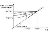
図5の通常モードマップにおいて、HEV→WSC切換線は、所定アクセル開度APO1未満の領域では、自動変速機ATが1速段のときに、エンジンEのアイドル回転数よりも小さな回転数となる下限車速VSP1よりも低い領域に設定されている。また、所定アクセル開度APO1以上の領域では、大きな駆動力を要求されることから、下限車速VSP1よりも高い車速VSP1'領域までWSC走行モードが設定されている。なお、バッテリSOCが低く、EV走行モードを達成できないときには、発進時等であってもWSC走行モードを選択するように構成されている。 In the normal mode map of FIG. 5, the HEV → WSC switching line has a rotational speed smaller than the idle rotational speed of the engine E when the automatic transmission AT is in the first speed in the region below the predetermined accelerator opening APO1. It is set in a region lower than the lower limit vehicle speed VSP1. Further, since a large driving force is required in a region where the accelerator opening APO1 is equal to or greater than the predetermined accelerator opening APO1, the WSC travel mode is set up to a vehicle speed VSP1 ′ region that is higher than the lower limit vehicle speed VSP1. When the battery SOC is low and the EV travel mode cannot be achieved, the WSC travel mode is selected even when starting.
アクセルペダル開度APOが大きいとき、その要求をアイドル回転数付近のエンジン回転数に対応したエンジントルクとモータジェネレータMGのトルクで達成するのは困難な場合がある。ここで、エンジントルクは、エンジン回転数が上昇すればより多くのトルクを出力できる。このことから、エンジン回転数を引き上げてより大きなトルクを出力させれば、例え下限車速VSP1よりも高い車速までWSC走行モードを実行しても、短時間でWSC走行モードからHEV走行モードに遷移させることができる。この場合が図5に示す下限車速VSP1'まで広げられたWSC領域である。 When the accelerator pedal opening APO is large, it may be difficult to achieve the request with the engine torque corresponding to the engine speed near the idle speed and the torque of the motor generator MG. Here, more engine torque can be output if the engine speed increases. From this, if the engine speed is increased and a larger torque is output, even if the WSC drive mode is executed up to a vehicle speed higher than the lower limit vehicle speed VSP1, the WSC drive mode is changed to the HEV drive mode in a short time. be able to. This case corresponds to the WSC region extended to the lower limit vehicle speed VSP1 ′ shown in FIG.
MWSCモードマップ内には、EV走行モード領域が設定されていない点で通常モードマップとは異なる。また、WSC走行モード領域として、アクセルペダル開度APOに応じて領域を変更せず、下限車速VSP1のみで領域が規定されている点で通常モードマップとは異なる。また、WSC走行モード領域内にMWSC走行モード領域が設定されている点で通常モードマップとは異なる。MWSC走行モード領域は、下限車速VSP1よりも低い所定車速VSP2と所定アクセル開度APO1よりも高い所定アクセル開度APO2とで囲まれた領域に設定されている。なお、MWSC走行モードについては後述する。 The MWSC mode map is different from the normal mode map in that the EV driving mode area is not set. Further, the WSC travel mode area is different from the normal mode map in that the area is not changed according to the accelerator pedal opening APO and the area is defined only by the lower limit vehicle speed VSP1. Moreover, it differs from the normal mode map in that the MWSC travel mode area is set in the WSC travel mode area. The MWSC travel mode region is set in a region surrounded by a predetermined vehicle speed VSP2 lower than the lower limit vehicle speed VSP1 and a predetermined accelerator opening APO2 higher than the predetermined accelerator opening APO1. The MWSC travel mode will be described later.
目標充放電演算部300では、図7に示す目標充放電量マップを用いて、バッテリSOCから目標充放電電力tPを演算する。
動作点指令部400では、アクセルペダル開度APOと、目標駆動力tFoOと、目標モードと、車速VSPと、目標充放電電力tPとから、これらの動作点到達目標として、過渡的な目標エンジントルクと目標モータジェネレータトルクと目標第2クラッチ伝達トルク容量と自動変速機ATの目標変速段と第1クラッチソレノイド電流指令を演算する。また、動作点指令部400には、EV走行モードからHEV走行モードに遷移するときにエンジンEを始動するエンジン始動制御部が設けられている。The target charge /
The operating
変速制御部500では、シフトマップに示すシフトスケジュールに沿って、目標第2クラッチ伝達トルク容量と目標変速段を達成するように自動変速機AT内のソレノイドバルブを駆動制御する。なお、シフトマップは、車速VSPとアクセルペダル開度APOに基づいて予め目標変速段が設定されたものである。 The
[WSC走行モード]
次に、WSC走行モードについて説明する。
WSC走行モードとは、エンジンEが作動した状態を維持している点に特徴があり、要求駆動力変化に対する応答性が高い。具体的には、第1クラッチCL1を完全締結し、第2クラッチCL2を要求駆動力に応じた伝達トルク容量としてスリップ制御し、エンジンEとモータジェネレータMGのうち少なくとも一方の駆動力を用いて走行する。[WSC travel mode]
Next, the WSC travel mode will be described.
The WSC travel mode is characterized in that the engine E is maintained in an operating state, and has high responsiveness to a required driving force change. Specifically, the first clutch CL1 is completely engaged, the second clutch CL2 is slip controlled as a transmission torque capacity corresponding to the required driving force, and the vehicle travels using at least one of the driving force of the engine E and the motor generator MG. To do.
実施例1のハイブリッド車両では、トルクコンバータのように回転数差を吸収する要素が存在しないため、第1クラッチCL1と第2クラッチCL2を完全締結すると、エンジンEの回転数に応じて車速が決まってしまう。エンジンEには自立回転を維持するためのアイドル回転数による下限値が存在し、このアイドル回転数は、エンジンの暖機運転等によりアイドルアップを行っていると、さらに下限値が高くなる。また、要求駆動力が高い状態では素早くHEV走行モードに遷移できない場合がある。 In the hybrid vehicle of the first embodiment, there is no element that absorbs the difference in rotational speed unlike the torque converter. Therefore, when the first clutch CL1 and the second clutch CL2 are completely engaged, the vehicle speed is determined according to the rotational speed of the engine E. End up. The engine E has a lower limit value based on the idling engine speed for maintaining the self-sustaining rotation. The idling engine speed is further increased when the engine is idling up due to warm-up operation of the engine or the like. In addition, when the required driving force is high, there may be a case where the HEV traveling mode cannot be quickly changed.
一方、EV走行モードでは、第1クラッチCL1を解放するため、上記エンジン回転数による下限値に伴う制限はない。しかしながら、バッテリSOCに基づく制限によってEV走行モードによる走行が困難な場合や、モータジェネレータMGのみで要求駆動力を達成できない領域では、エンジンEによって安定したトルクを発生する以外に手段がない。 On the other hand, in the EV travel mode, since the first clutch CL1 is released, there is no limit associated with the lower limit value due to the engine speed. However, in the case where it is difficult to travel in the EV travel mode due to the restriction based on the battery SOC, or in the region where the required driving force cannot be achieved only by the motor generator MG, there is no means other than generating stable torque by the engine E.
そこで、上記下限値に相当する車速よりも低車速領域であって、かつ、EV走行モードによる走行が困難な場合やモータジェネレータMGのみでは要求駆動力を達成できない領域では、エンジン回転数を所定の下限回転数に維持し、第2クラッチCL2をスリップ制御させ、エンジントルクを用いて走行するWSC走行モードを選択する。 Therefore, in a vehicle speed range lower than the vehicle speed corresponding to the above lower limit value, and when it is difficult to travel in the EV travel mode, or in a region where the required driving force cannot be achieved only by the motor generator MG, the engine speed is set to a predetermined value. While maintaining the lower limit rotational speed, the second clutch CL2 is slip-controlled, and the WSC traveling mode for traveling using the engine torque is selected.
図8はWSC走行モードにおけるエンジン動作点設定処理を表す概略図、図9はWSC走行モードにおけるエンジン目標回転数を表すマップである。
WSC走行モードにおいて、ドライバがアクセルペダルを操作すると、図9に基づいてアクセルペダル開度に応じた目標エンジン回転数特性が選択され、この特性に沿って車速に応じた目標エンジン回転数が設定される。そして、図8に示すエンジン動作点設定処理によって目標エンジン回転数に対応した目標エンジントルクが演算される。FIG. 8 is a schematic diagram showing the engine operating point setting process in the WSC running mode, and FIG. 9 is a map showing the engine target speed in the WSC running mode.
When the driver operates the accelerator pedal in the WSC travel mode, the target engine speed characteristic corresponding to the accelerator pedal opening is selected based on FIG. 9, and the target engine speed corresponding to the vehicle speed is set along this characteristic. The Then, the target engine torque corresponding to the target engine speed is calculated by the engine operating point setting process shown in FIG.
ここで、エンジンEの動作点をエンジン回転数とエンジントルクにより規定される点と定義する。図8に示すように、エンジン動作点は、エンジンEの出力効率が高い動作点を結んだ線(以下、α線)上で運転することが望まれる。
ところが、上述のようにエンジン回転数を設定した場合、ドライバのアクセルペダル操作量(要求駆動力)によってはα線から離れた動作点を選択することとなる。そこで、エンジン動作点をα線に近づけるために、目標エンジントルクは、α線を考慮した値にフィードフォワード制御される。Here, the operating point of the engine E is defined as a point defined by the engine speed and the engine torque. As shown in FIG. 8, it is desirable that the engine operating point is operated on a line (hereinafter referred to as “α line”) connecting operating points with high output efficiency of the engine E.
However, when the engine speed is set as described above, an operating point away from the α line is selected depending on the accelerator pedal operation amount (required driving force) of the driver. Therefore, in order to bring the engine operating point closer to the α line, the target engine torque is feedforward controlled to a value that takes the α line into consideration.
一方、モータジェネレータMGは、設定されたエンジン回転数を目標回転数とする回転数フィードバック制御が実行される。今、エンジンEとモータジェネレータMGは直結状態とされていることから、モータジェネレータMGが目標回転数を維持するように制御されることで、エンジンEの回転数も自動的にフィードバック制御されることとなる。 On the other hand, the motor generator MG executes the rotational speed feedback control using the set engine rotational speed as the target rotational speed. Since the engine E and the motor generator MG are now in a direct connection state, the motor generator MG is controlled so as to maintain the target rotational speed, and the rotational speed of the engine E is also automatically feedback-controlled. It becomes.
このとき、モータジェネレータMGが出力するトルクは、α線を考慮して決定された目標エンジントルクと要求駆動力との偏差を埋めるように自動的に制御される。モータジェネレータMGでは、上記偏差を埋めるように基礎的なトルク制御量(回生・力行)が与えられ、さらに、目標エンジン回転数と一致するようにフィードバック制御される。 At this time, the torque output from motor generator MG is automatically controlled so as to fill the deviation between the target engine torque determined in consideration of the α-ray and the required driving force. In motor generator MG, a basic torque control amount (regeneration / power running) is given so as to fill the deviation, and feedback control is performed so as to coincide with the target engine speed.
あるエンジン回転数において、要求駆動力がα線上の駆動力よりも小さい場合、エンジン出力トルクを大きくした方がエンジン出力効率は上昇する。このとき、出力を上げた分のエネルギをモータジェネレータMGにより回収することで、第2クラッチCL2に入力されるトルク自体はドライバの要求トルクとしつつ、効率の良い発電が可能となる。 When the required driving force is smaller than the driving force on the α line at a certain engine speed, the engine output efficiency increases as the engine output torque is increased. At this time, the motor generator MG recovers the energy corresponding to the increased output, so that efficient power generation is possible while the torque itself input to the second clutch CL2 is set to the torque required by the driver.
ただし、バッテリSOCの状態によって発電可能なトルク上限値が決定されるため、バッテリSOCからの要求発電出力(SOC要求発電電力)と、現在の動作点におけるトルクとα線上のトルクとの偏差(α線発電電力)との大小関係を考慮する必要がある。 However, since the upper limit of torque that can be generated is determined according to the state of the battery SOC, the required power generation output (SOC required power generation power) from the battery SOC and the deviation between the torque at the current operating point and the torque on the α line (α It is necessary to consider the magnitude relationship with the (line generated power).
図8(a)は、α線発電電力がSOC要求発電電力よりも大きい場合の概略図である。SOC要求発電電力以上にはエンジン出力トルクを上昇させることができないため、α線上に動作点を移動させることはできない。ただし、より効率の高い点へ移動させることで燃費効率を改善する。 FIG. 8A is a schematic diagram when the α-ray generated power is larger than the SOC required generated power. Since the engine output torque cannot be increased above the SOC required power generation, the operating point cannot be moved on the α line. However, fuel efficiency is improved by moving to a more efficient point.
図8(b)は、α線発電電力がSOC要求発電電力よりも小さい場合の概略図である。SOC要求発電電力の範囲内であれば、エンジン動作点をα線上に移動させることができるため、この場合は、最も燃費効率の高い動作点を維持しつつ発電することができる。 FIG. 8B is a schematic diagram when the α-ray generated power is smaller than the SOC required generated power. Since the engine operating point can be moved on the α line within the SOC required power generation range, in this case, it is possible to generate power while maintaining the operating point with the highest fuel efficiency.
図8(c)は、エンジン動作点がα線よりも高い場合の概略図である。要求駆動力に応じた動作点がα線よりも高いときは、バッテリSOCに余裕があることを条件として、エンジントルクを低下させ、不足分をモータジェネレータMGの力行により補う。これにより、燃費効率を高くしつつ要求駆動力を達成することができる。 FIG. 8C is a schematic diagram when the engine operating point is higher than the α line. When the operating point corresponding to the required driving force is higher than the α line, the engine torque is reduced on the condition that the battery SOC has a margin, and the shortage is compensated by the power running of the motor generator MG. As a result, the required driving force can be achieved while improving the fuel efficiency.
次に、WSC走行モード領域を、推定勾配に応じて変更している点について説明する。図10は車速を所定状態で上昇させる際のエンジン回転数マップである。
平坦路において、アクセルペダル開度がAPO1よりも大きな値の場合、WSC走行モード領域は下限車速VSP1よりも高い車速領域まで実行される。このとき、車速の上昇に伴って図9に示すマップのように徐々に目標エンジン回転数は上昇する。そして、VSP1'に相当する車速に到達すると、第2クラッチCL2のスリップ状態は解消され、HEV走行モードに遷移する。Next, the point that the WSC traveling mode area is changed according to the estimated gradient will be described. FIG. 10 is an engine speed map when the vehicle speed is increased in a predetermined state.
When the accelerator pedal opening is larger than APO1 on a flat road, the WSC drive mode region is executed up to a vehicle speed region higher than the lower limit vehicle speed VSP1. At this time, as the vehicle speed increases, the target engine speed gradually increases as shown in the map of FIG. Then, when the vehicle speed corresponding to VSP1 ′ is reached, the slip state of the second clutch CL2 is canceled and the state transits to the HEV travel mode.
推定勾配が所定勾配(g1もしくはg2)より大きい勾配路において、上記と同じ車速上昇状態を維持しようとすると、それだけ大きなアクセルペダル開度となる。このとき、第2クラッチCL2の伝達トルク容量TCL2は平坦路に比べて大きくなる。この状態で、仮に図9に示すマップのようにWSC走行モード領域を拡大してしまうと、第2クラッチCL2は強い締結力でのスリップ状態を継続することとなり、発熱量が過剰となるおそれがある。そこで、推定勾配が大きい勾配路のときに選択される図6のMWSC対応モードマップでは、WSC走行モード領域を不要に広げることなく、車速VSP1に相当する領域までとする。これにより、WSC走行モードにおける過剰な発熱を回避する。 If an attempt is made to maintain the same vehicle speed increase state as described above on a gradient road where the estimated gradient is larger than the predetermined gradient (g1 or g2), the accelerator pedal opening is increased accordingly. At this time, the transmission torque capacity TCL2 of the second clutch CL2 is larger than that on a flat road. In this state, if the WSC travel mode area is enlarged as shown in the map shown in FIG. 9, the second clutch CL2 will continue to slip with a strong engagement force, and the amount of heat generated may be excessive. is there. Therefore, in the MWSC compatible mode map of FIG. 6 selected when the estimated slope is large, the WSC travel mode area is not unnecessarily widened, but the area corresponding to the vehicle speed VSP1. This avoids excessive heat generation in the WSC travel mode.
[MWSC走行モード]
推定勾配が所定勾配(g1もしくはg2)より大きいときに、例えば、ブレーキペダル操作を行うことなく車両を停止状態もしくは微速発進状態に維持しようとすると、平坦路に比べて大きな駆動力が要求される。自車両の荷重負荷に対向する必要があるからである。[MWSC driving mode]
When the estimated gradient is larger than the predetermined gradient (g1 or g2), for example, if it is attempted to keep the vehicle in a stopped state or a slow start state without operating the brake pedal, a large driving force is required compared to a flat road . This is because it is necessary to face the load load of the host vehicle.
第2クラッチCL2のスリップによる発熱を回避する観点から、バッテリSOCに余裕があるときはEV走行モードを選択することも考えられる。このとき、EV走行モード領域からWSC走行モード領域に遷移したときにはエンジン始動を行う必要があり、モータジェネレータMGはエンジン始動用トルクを確保した状態で駆動トルクを出力するため、駆動トルク上限値が不要に狭められる。 From the viewpoint of avoiding heat generation due to the slip of the second clutch CL2, it is also conceivable to select the EV travel mode when the battery SOC has a margin. At this time, it is necessary to start the engine when transitioning from the EV travel mode region to the WSC travel mode region, and the motor generator MG outputs the drive torque while securing the engine start torque, so the drive torque upper limit value is unnecessary. It is narrowed to.
また、EV走行モードにおいてモータジェネレータMGにトルクだけを出力し、モータジェネレータMGの回転を停止もしくは極低速回転すると、インバータのスイッチング素子にロック電流が流れ(電流が1つの素子に流れ続ける現象)、耐久性の低下を招くおそれがある。 Moreover, when only the torque is output to the motor generator MG in the EV travel mode and the motor generator MG stops or rotates at a very low speed, a lock current flows through the switching element of the inverter (a phenomenon in which the current continues to flow through one element), There is a risk of lowering durability.
また、1速でエンジンEのアイドル回転数に相当する下限車速VSP1よりも低い領域(VSP2以下の領域)において、エンジンE自体は、アイドル回転数より低下させることができない。このとき、WSC走行モードを選択すると、第2クラッチCL2のスリップ量が大きくなり、第2クラッチCL2の耐久性に影響を与えるおそれがある。 Further, in a region lower than the lower limit vehicle speed VSP1 corresponding to the idle speed of the engine E at the first speed (region of VSP2 or less), the engine E itself cannot be reduced below the idle speed. At this time, if the WSC travel mode is selected, the slip amount of the second clutch CL2 increases, which may affect the durability of the second clutch CL2.
特に、勾配路では、平坦路に比べて大きな駆動力が要求されていることから、第2クラッチCL2に要求される伝達トルク容量は高くなり、高トルクで高スリップ量の状態が継続されることは、第2クラッチCL2の耐久性の低下を招きやすい。また、車速の上昇もゆっくりとなることから、HEV走行モードへの遷移までに時間がかかり、さらに発熱するおそれがある。 In particular, since a large driving force is required on a slope road as compared with a flat road, the transmission torque capacity required for the second clutch CL2 is increased, and a high torque and high slip amount state is continued. Tends to cause a decrease in durability of the second clutch CL2. In addition, since the vehicle speed rises slowly, it takes time until the transition to the HEV travel mode, and there is a risk of further generating heat.
そこで、エンジンEを作動させたまま、第1クラッチCL1を解放し、第2クラッチCL2の伝達トルク容量をドライバの要求駆動力に制御しつつ、モータジェネレータMGの回転数が第2クラッチCL2の出力回転数よりも所定回転数高い目標回転数にフィードバック制御するMWSC走行モードを設定した。 Therefore, with the engine E running, the first clutch CL1 is released and the transmission torque capacity of the second clutch CL2 is controlled to the driver's required driving force, while the rotational speed of the motor generator MG is the output of the second clutch CL2. A MWSC driving mode was set for feedback control to a target rotational speed that is a predetermined rotational speed higher than the rotational speed.
言い換えると、モータジェネレータMGの回転状態をエンジンのアイドル回転数よりも低い回転数としつつ第2クラッチCL2をスリップ制御するものである。同時に、エンジンEはアイドル回転数を目標回転数とするフィードバック制御に切り換える。WSC走行モードでは、モータジェネレータMGの回転数フィードバック制御によりエンジン回転数が維持されていた。これに対し、第1クラッチCL1が解放されると、モータジェネレータMGによってエンジン回転数をアイドル回転数に制御できなくなる。よって、エンジンE自体によりエンジン回転数フィードバック制御を行う。 In other words, the second clutch CL2 is slip-controlled while the rotational state of the motor generator MG is set to a rotational speed lower than the idle rotational speed of the engine. At the same time, the engine E switches to feedback control in which the idling speed is the target speed. In the WSC travel mode, the engine speed was maintained by the rotational speed feedback control of the motor generator MG. On the other hand, when the first clutch CL1 is released, the engine speed cannot be controlled to the idle speed by the motor generator MG. Therefore, engine speed feedback control is performed by the engine E itself.
[保護制御]
次に、実施例1の保護制御について説明する。
WSC走行モードおよびMWSC走行モードでストール停車状態が継続すると、第2クラッチCL2のスリップ量が過多の状態が継続し、第2クラッチCL2が過熱するおそれがある。
そこで、実施例1では、ストール停車状態を検出した場合、温度センサ10aにより検出された第2クラッチCL2の温度が過熱を表す所定温度以上であるとき、第1クラッチCL1および第2クラッチCL2を完全締結させてエンジンをストールさせ、第2クラッチCL2の保護を図る保護制御を実施する。[Protection control]
Next, protection control according to the first embodiment will be described.
If the stall stop state continues in the WSC travel mode and the MWSC travel mode, the state in which the slip amount of the second clutch CL2 is excessive continues and the second clutch CL2 may be overheated.
Therefore, in the first embodiment, when the stall stop state is detected, when the temperature of the second clutch CL2 detected by the temperature sensor 10a is equal to or higher than a predetermined temperature indicating overheating, the first clutch CL1 and the second clutch CL2 are completely engaged. The engine is stalled by engaging, and protection control is performed to protect the second clutch CL2.
この保護制御を実施する構成として、統合コントローラ10の動作点指令部400は、ストール停車状態判定部(ストール停車状態判定手段)401と、クラッチ保護制御部(クラッチ保護制御手段)402と、駆動力制限部403とを備える。 As a configuration for performing this protection control, the operating
ストール停車状態判定部401は、路面勾配を推定する路面勾配推定演算部201により推定された路面勾配と、車速センサ17により検出された車速と、アクセル開度センサ16により検出されたアクセル開度に基づいて、ストール停車状態であるか否かを判定する。ここで、ストール停車状態は、登坂路でドライバがアクセルを踏んでいる場合、車速がほぼゼロであるときストール停車状態であると判定し、それ以外のときストール停車状態ではないと判定する。 The stall stop
クラッチ保護制御部402は、ストール停車状態判定部401によりストール停車状態であると判定された場合、温度センサ10aにより検出された第2クラッチCL2の温度が所定温度以上であるときには、第1クラッチCL1および第2クラッチCL2を完全締結させる指令を出力する。このとき、車両の駆動力増加に伴う急発進を防止するために、第2クラッチCL2の第2クラッチ伝達トルク容量TCL2を、上限トルク容量まで所定の変化率で徐々に上昇させる。 When it is determined by the stall stop
また、クラッチ保護制御部402は、保護制御時、モータジェネレータMGを目標回転数に応じて回転数制御すると共にエンジンEを目標エンジントルクに応じてトルク制御する。
保護制御におけるモータジェネレータMGの目標モータ回転数は、目標時間後にモータ回転数が所定回転数となるようなモータ回転数の下降勾配を決め、この下降勾配が得られるような回転数を設定する。ここで、目標時間は、当該保護制御により車両を前進させる距離と時間とに応じて適宜設定する。また、所定回転数は、エンジンEの低回転共振帯(エンジンと車両フロアとが共振して車両の音振性能が悪化する回転数領域)の上限値よりもオフセット回転数だけ高い回転数とする。
なお、モータ回転数が所定回転数に到達した場合、保護制御を終了するまでの間、目標回転数をゼロとする。Further, at the time of protection control, the clutch
The target motor rotational speed of the motor generator MG in the protection control is determined so as to determine a descending gradient of the motor rotational speed so that the motor rotational speed becomes a predetermined rotational speed after the target time, and to obtain this downward gradient. Here, the target time is appropriately set according to the distance and time to advance the vehicle by the protection control. In addition, the predetermined rotational speed is a rotational speed that is higher by an offset rotational speed than the upper limit value of the low rotational resonance band of engine E (the rotational speed region where the engine and the vehicle floor resonate and the sound vibration performance of the vehicle deteriorates). .
When the motor rotation speed reaches the predetermined rotation speed, the target rotation speed is set to zero until the protection control is finished.
保護制御におけるエンジンEの目標エンジントルクは、エンジン回転数が上記所定回転数となるまでの間、エンジントルク+モータトルクが第2クラッチ伝達トルク容量TCL2以下となるようなエンジントルクとする。
なお、エンジン回転数が所定回転数に到達した場合、保護制御を終了するまでの間、エンジンEのフューエルカットを行う。The target engine torque of the engine E in the protection control is an engine torque such that the engine torque + the motor torque is equal to or less than the second clutch transmission torque capacity TCL2 until the engine speed reaches the predetermined speed.
When the engine speed reaches a predetermined speed, the fuel cut of the engine E is performed until the protection control is finished.
[切り替え処理]
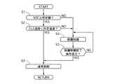
図11は、通常制御と保護制御とを切り替える切り替え処理の流れを示すフローチャートで、以下、各ステップについて説明する。ここで、通常制御とは、通常のWSC走行モードまたはMWSC走行モードにおいて、車速VSP、アクセル開度APO、バッテリSOC等に基づく、エンジンE、モータジェネレータMG、第1クラッチCL1、第2クラッチCL2の制御をいう。なお、この処理は、WSC走行モードまたはMWSC走行モードにおいてストール停車状態を検出したとき、所定の制御周期(例えば、10ms)で繰り返し実行する。[Switching process]
FIG. 11 is a flowchart showing a flow of switching processing for switching between normal control and protection control. Each step will be described below. Here, the normal control refers to the engine E, the motor generator MG, the first clutch CL1, and the second clutch CL2 based on the vehicle speed VSP, the accelerator opening APO, the battery SOC, and the like in the normal WSC traveling mode or MWSC traveling mode. Refers to control. This process is repeatedly executed at a predetermined control cycle (for example, 10 ms) when a stall stop state is detected in the WSC drive mode or the MWSC drive mode.
ステップS1では、バッテリSOCが所定値(例えば、35%)以上であるか否かを判定する。YESの場合にはステップS2へ移行し、NOの場合にはステップS4へ移行する。
ステップS2では、第2クラッチCL2の温度が過熱を表す所定温度よりも低いか否かを判定する。YESの場合にはステップS3へ移行し、NOの場合にはステップS4へ移行する。
ステップS3では、通常制御を実施し、リターンへ移行する。In step S1, it is determined whether or not the battery SOC is equal to or greater than a predetermined value (for example, 35%). If YES, the process proceeds to step S2, and if NO, the process proceeds to step S4.
In step S2, it is determined whether or not the temperature of the second clutch CL2 is lower than a predetermined temperature representing overheating. If YES, the process proceeds to step S3. If NO, the process proceeds to step S4.
In step S3, normal control is performed, and the process proceeds to return.
ステップS4では、両クラッチCL1,CL2を完全締結させる保護制御を実施し、リターンへ移行する。
ステップS5では、保護制御終了条件が成立しているか否かを判定する。YESの場合にはステップS3へ移行し、NOの場合にはステップS4へ移行する。ここで、保護制御終了条件は、以下の3条件を全て満たした場合に成立するものとする。
1.ブレーキON
2.第2クラッチCL2の温度が所定温度未満
3.バッテリSOCが所定値以上In step S4, protection control for completely engaging both clutches CL1 and CL2 is performed, and a return is made.
In step S5, it is determined whether or not a protection control end condition is satisfied. If YES, the process proceeds to step S3. If NO, the process proceeds to step S4. Here, it is assumed that the protection control end condition is satisfied when all of the following three conditions are satisfied.
1.Brake ON
2. The temperature of the second clutch CL2 is less than the specified temperature
3. Battery SOC is more than the specified value
ここで、保護制御から通常制御に復帰する際、第2クラッチCL2は完全締結状態であるため、PレンジまたはNレンジ相当の状態、すなわち、第2クラッチCL2を開放した後、通常制御に復帰することとする。 Here, when returning from the protection control to the normal control, the second clutch CL2 is in the completely engaged state, so that the state corresponding to the P range or the N range, that is, after the second clutch CL2 is released, returns to the normal control. I will do it.
次に、作用を説明する。
図12は、実施例1の第2クラッチ保護作用を示すタイムチャートである。
時点t1では、ストール停車状態であると判定し、WSC走行モードによる通常制御から保護制御へ移行する。
時点t1〜t2の区間では、時点t1からディレイ時間が経過していないため、WSC走行モードにおける通常制御を継続する。ここで、ディレイ時間は、アクセル開度APOが高いほど長く設定する。第2クラッチCL2の過熱を判定してからエンジンストールさせるまでの時間を、アクセル開度APOにかかわらず一定とするためである。Next, the operation will be described.
FIG. 12 is a time chart showing the second clutch protection action of the first embodiment.
At time t1, it is determined that the vehicle is stalled, and the control shifts from normal control in the WSC travel mode to protection control.
In the section from the time point t1 to t2, since the delay time has not elapsed from the time point t1, the normal control in the WSC traveling mode is continued. Here, the delay time is set longer as the accelerator opening APO is higher. This is because the time from when it is determined that the second clutch CL2 is overheated until the engine is stalled is constant regardless of the accelerator opening APO.
時点t2では、時点t1からディレイ時間が経過したため、時点t2〜t3の区間では、第2クラッチCL2の第2クラッチ伝達トルク容量TCL2を、アクセル開度APO、すなわちドライバ要求トルクに応じた値から、第2クラッチCL2が完全締結状態となる第2クラッチCL2の上限トルク容量まで所定の立ち上げ勾配で徐々に増加させる。このとき、クラッチトルクを立ち上げることで車両の加速度は増加し、車両は僅かに前進するが、駆動力の立ち上げ勾配を滑らかにしているため、急発進を防止できる。 Since the delay time has elapsed from time t1 at time t2, the second clutch transmission torque capacity TCL2 of the second clutch CL2 is determined from the value corresponding to the accelerator opening APO, that is, the driver required torque, during the period from time t2 to t3. The second clutch CL2 is gradually increased at a predetermined ramp up to the upper limit torque capacity of the second clutch CL2 in which the second clutch CL2 is completely engaged. At this time, by raising the clutch torque, the acceleration of the vehicle increases and the vehicle slightly moves forward. However, since the rising gradient of the driving force is smoothed, sudden start can be prevented.
時点t2から僅かに遅れて、モータジェネレータMGのモータ回転数が時点t2から所定時間経過後に所定回転数(エンジンEの低回転共振帯の上限値(400rpm)よりもオフセット回転数だけ高い回転数)となるよう、目標回転数を徐々に低下させる回転数制御を行う。これにより、時点t2〜t4の時間、すなわち車両を前進させる時間と距離を任意に調整できる。 Slightly delayed from time t2, the motor speed of the motor generator MG is the predetermined speed after a predetermined time has elapsed from time t2 (the speed that is higher by the offset speed than the upper limit (400rpm) of the low-speed resonance band of engine E) Rotational speed control for gradually reducing the target rotational speed is performed so that Thereby, the time from the time point t2 to t4, that is, the time and distance for moving the vehicle forward can be arbitrarily adjusted.
上記モータジェネレータMGの回転数制御と同時に、エンジンEの目標エンジントルクを、エンジントルクとモータトルクとの和がクラッチトルク以下となるようなエンジントルクとするトルク制御を行う。これにより、時点t2〜t4の区間では、エンジン回転数(=モータ回転数)はエンジントルク制限により低下し、モータトルクは、目標回転数制御により制限されるため、第2クラッチCL2の過熱を抑制できる。 Simultaneously with the rotational speed control of the motor generator MG, torque control is performed so that the target engine torque of the engine E is engine torque such that the sum of the engine torque and the motor torque is equal to or less than the clutch torque. As a result, in the section from time t2 to t4, the engine speed (= motor speed) decreases due to the engine torque limit, and the motor torque is limited by the target speed control, thereby suppressing overheating of the second clutch CL2. it can.
時点t3では、第2クラッチ伝達トルク容量TCL2が第2クラッチCL2の上限トルク容量に到達し、時点t3から遅れて、ドライバは車両の加速度が増加することで、アクセルペダルからブレーキペダルへの踏み替えを開始する。
時点t4では、エンジンEがストールする。また、エンジン回転数が所定回転数(低回転共振帯の上限値+オフセット回転数)に達したため、モータ回転数制御の目標回転数をゼロにすると共に、エンジンEのフューエルカットを行う。At time t3, the second clutch transmission torque capacity TCL2 reaches the upper limit torque capacity of the second clutch CL2, and after the time t3, the driver increases the acceleration of the vehicle so that the driver switches from the accelerator pedal to the brake pedal. To start.
At time t4, engine E stalls. Further, since the engine speed has reached a predetermined speed (the upper limit value of the low-speed resonance band + the offset speed), the target speed of the motor speed control is set to zero and the fuel cut of the engine E is performed.
時点t4〜t5の区間では、エンジンストールにより車両の加速度が減少し、車両は僅かに後退するが、駆動輪RL,RRは停止したエンジンEと直結状態であるため、エンジンEのフリクション(エンジンブレーキ)を利用して車両のずり下がりを抑えることができる。また、時点t2〜t4の区間において車両を所定距離前進させているため、保護制御開始時点の位置よりも低い位置に車両が後退することはない。
時点t5では、ドライバがブレーキペダルの踏み込みを開始するため、車両は停止状態となり、時点t6では、ブレーキペダルの踏み込み量が一定となる。In the period from time t4 to t5, the acceleration of the vehicle decreases due to the engine stall, and the vehicle slightly moves backward, but the driving wheels RL and RR are in a directly connected state with the stopped engine E, so the friction of the engine E (engine brake) ) Can be used to suppress vehicle slippage. Further, since the vehicle is moved forward by a predetermined distance in the section from the time point t2 to t4, the vehicle does not move backward to a position lower than the position at the protection control start time point.
At time t5, the driver starts depressing the brake pedal, so the vehicle is stopped. At time t6, the brake pedal depressing amount is constant.
以上のように、時点t2〜t3の区間では、第2クラッチ伝達トルク容量TCL2を上限トルク容量まで高め、第2クラッチCL2を完全締結させるため、第2クラッチCL2の過熱を抑制し、保護を図ることができる。 As described above, in the section from the time point t2 to t3, the second clutch transmission torque capacity TCL2 is increased to the upper limit torque capacity and the second clutch CL2 is completely engaged. Therefore, overheating of the second clutch CL2 is suppressed and protection is achieved. be able to.
また、時点t2〜t4の区間では、車両を一端所定距離だけ前進させ、その後エンジンストールにより後退させることで、エンジンストール前後の加速度変化とエンジン停止音により、ドライバに対しアクセルペダルからブレーキペダルへの踏み替えを促すことができ、車両のずり下がりを抑制できる。 Also, in the section from time t2 to t4, the vehicle is moved forward by a predetermined distance and then moved backward by engine stall, so that the driver changes the acceleration pedal before and after the engine stall and the engine stop sound from the accelerator pedal to the brake pedal. It is possible to prompt a step change, and to suppress the vehicle from falling down.
次に、効果を説明する。
以上説明したように、実施例1のハイブリッド車両の制御装置にあっては、以下に列挙する効果を奏する。Next, the effect will be described.
As described above, the hybrid vehicle control apparatus according to the first embodiment has the following effects.
エンジンEと、モータジェネレータMGと、エンジンEとモータジェネレータMGとの間に介装し、エンジンEとモータジェネレータMGとを断接する第1クラッチCL1と、モータジェネレータMGと駆動輪RL,RRとの間に介装し、モータジェネレータMGと駆動輪RL,RRとを断接する第2クラッチCL2と、第2クラッチCL2の温度を検出する温度センサ10aと、登坂路でドライバがアクセルペダルを調整し車両停止状態を維持するストール停車状態を判定するストール停車状態判定部401と、ストール停車状態と判定された場合、第2クラッチCL2の温度が所定温度以上であるときには、第1クラッチCL1および第2クラッチCL2を共に締結するクラッチ保護制御部402と、を備える。 A first clutch CL1 that is interposed between the engine E, the motor generator MG, the engine E and the motor generator MG, and connects and disconnects the engine E and the motor generator MG, and the motor generator MG and the drive wheels RL and RR. A second clutch CL2 that connects and disconnects the motor generator MG and the drive wheels RL and RR, a temperature sensor 10a that detects the temperature of the second clutch CL2, and a vehicle that adjusts the accelerator pedal on the uphill road. A stall stop
すなわち、第2クラッチCL2が過熱した場合には、第2クラッチCL2を完全締結することにより、さらなる温度上昇を抑制でき、第2クラッチCL2の保護を図ることができる。
また、第1クラッチCL1および第2クラッチCL2を完全締結することにより、エンジンストールを発生させ、その前後に生じる車両挙動変化およびエンジン停止音により、ドライバにアクセルペダルからブレーキペダルへの踏み替えを促すことができ、車両のずり下がりを抑制できる。That is, when the second clutch CL2 is overheated, the second clutch CL2 is completely engaged, whereby a further increase in temperature can be suppressed and the second clutch CL2 can be protected.
Further, by completely engaging the first clutch CL1 and the second clutch CL2, an engine stall is generated, and the driver is prompted to switch from the accelerator pedal to the brake pedal due to vehicle behavior change and engine stop sound that occur before and after the engine stall. And the vehicle can be prevented from sliding down.
さらに、第1クラッチCL1および第2クラッチCL2を完全締結することにより、駆動輪RL,RRとエンジンEとを直結状態とし、エンジンのフリクション(エンジンブレーキ)によりエンジンストール後の車両のずり下がりを抑えることができる。 Further, by completely engaging the first clutch CL1 and the second clutch CL2, the drive wheels RL and RR and the engine E are brought into a direct connection state, and the vehicle friction after engine stall is suppressed by engine friction (engine brake). be able to.
(他の実施例)
以上、本発明のハイブリッド車両の制御装置を実施例に基づき説明してきたが、具体的な構成については、実施例に限られるものではなく、特許請求の範囲の各請求項に係る発明の要旨を逸脱しない限り、設計の変更や追加等は許容される。(Other examples)
As mentioned above, although the control apparatus of the hybrid vehicle of this invention has been demonstrated based on the Example, about a concrete structure, it is not restricted to an Example, The summary of the invention which concerns on each claim of a Claim Unless it deviates, design changes and additions are allowed.
例えば、実施例では、第2クラッチとして自動変速機に内蔵されたクラッチを利用する例を示したが、モータジェネレータと変速機との間に第2クラッチを介装する構成、または、変速機と駆動輪との間に第2クラッチを介装する構成も採用できる。 For example, in the embodiment, the example in which the clutch built in the automatic transmission is used as the second clutch has been described. However, the configuration in which the second clutch is interposed between the motor generator and the transmission, or the transmission A configuration in which a second clutch is interposed between the driving wheels can also be employed.
また、実施例では、バッテリの保護を目的とし、バッテリSOCが所定値を下回る場合にも保護制御を開始する例を示したが、第2クラッチの過熱判定のみを保護制御の開始および終了条件としてもよい。
ドライバによるアクセルペダルからブレーキペダルへの踏み替えが遅れた場合には、自動ブレーキにより車両に制動力を作用させ、車両のずり下がりを抑制してもよい。Further, in the embodiment, an example is shown in which protection control is started even when the battery SOC is lower than a predetermined value for the purpose of battery protection. However, only the overheat determination of the second clutch is used as the start and end conditions for protection control. Also good.
When the driver's switch from the accelerator pedal to the brake pedal is delayed, a braking force may be applied to the vehicle by automatic braking to suppress the vehicle from sliding down.
E エンジン
FW フライホイール
CL1 第1クラッチ
MG モータジェネレータ(モータ)
CL2 第2クラッチ
AT 自動変速機
PS プロペラシャフト
DF ディファレンシャル
DSL 左ドライブシャフト
DSR 右ドライブシャフト
RL 左後輪(駆動輪)
RR 右後輪(駆動輪)
FL 左前輪
FR 右前輪
1 エンジンコントローラ
2 モータコントローラ
3 インバータ
4 バッテリ
5 第1クラッチコントローラ
6 第1クラッチ油圧ユニット
7 ATコントローラ
8 第2クラッチ油圧ユニット
9 ブレーキコントローラ
10 統合コントローラ
10a 温度センサ(温度検出手段)
10b 加速度センサ
24 ブレーキ油圧センサ
100 目標駆動力演算部
200 モード選択部
300 目標充放電演算部
400 動作点指令部
401 ストール停車状態判定部(ストール停車状態判定手段)
402 クラッチ保護制御部(クラッチ保護制御手段)
500 変速制御部E engine
FW flywheel
CL1 1st clutch
MG Motor generator (motor)
CL2 2nd clutch
AT automatic transmission
PS propeller shaft
DF differential
DSL left drive shaft
DSR right drive shaft
RL Left rear wheel (drive wheel)
RR Right rear wheel (drive wheel)
FL Left front wheel
FR Right front wheel 1
100 Target driving force calculator
200 Mode selection section
300 Target charge / discharge calculator
400 Operating point command section
401 Stall stop state determination unit (stall stop state determination means)
402 Clutch protection control unit (clutch protection control means)
500 Shift control
Claims (1)
Translated fromJapaneseモータと、
前記エンジンと前記モータとの間に介装し、前記エンジンと前記モータとを断接する第1クラッチと、
前記モータと駆動輪との間に介装し、前記モータと前記駆動輪とを断接する第2クラッチと、
前記第2クラッチの温度を検出する温度検出手段と、
登坂路でドライバがアクセルペダルを調整し車両停車状態を維持するストール停車状態を判定するストール停車状態判定手段と、
前記ストール停車状態と判定された場合、前記第2クラッチの温度が所定温度以上であるときには、前記第1クラッチおよび前記第2クラッチを共に締結すると共に、前記エンジンがストールするようエンジントルク制限を行うクラッチ保護制御手段と、
を備えることを特徴とするハイブリッド車両の制御装置。Engine,
A motor,
A first clutch that is interposed between the engine and the motor and connects and disconnects the engine and the motor;
A second clutch that is interposed between the motor and the drive wheel, and connects and disconnects the motor and the drive wheel;
Temperature detecting means for detecting the temperature of the second clutch;
A stall stop state determination means for determining a stall stop state in which the driver adjusts the accelerator pedal on the uphill road and maintains the vehicle stop state; and
If it is determined that the stall is in a stalled state, and if the temperature of the second clutch is equal to or higher than a predetermined temperature, the first clutch and the second clutch are both engaged, and theengine torque is limited so that the engine stalls. Clutch protection control means;
A control apparatus for a hybrid vehicle, comprising:
Priority Applications (1)
| Application Number | Priority Date | Filing Date | Title |
|---|---|---|---|
| JP2008328896AJP5024278B2 (en) | 2008-12-25 | 2008-12-25 | Control device for hybrid vehicle. |
Applications Claiming Priority (1)
| Application Number | Priority Date | Filing Date | Title |
|---|---|---|---|
| JP2008328896AJP5024278B2 (en) | 2008-12-25 | 2008-12-25 | Control device for hybrid vehicle. |
Publications (2)
| Publication Number | Publication Date |
|---|---|
| JP2010149649A JP2010149649A (en) | 2010-07-08 |
| JP5024278B2true JP5024278B2 (en) | 2012-09-12 |
Family
ID=42569242
Family Applications (1)
| Application Number | Title | Priority Date | Filing Date |
|---|---|---|---|
| JP2008328896AActiveJP5024278B2 (en) | 2008-12-25 | 2008-12-25 | Control device for hybrid vehicle. |
Country Status (1)
| Country | Link |
|---|---|
| JP (1) | JP5024278B2 (en) |
Cited By (1)
| Publication number | Priority date | Publication date | Assignee | Title |
|---|---|---|---|---|
| CN105556182A (en)* | 2013-09-19 | 2016-05-04 | 舍弗勒技术股份两合公司 | Method for supplying power to a control device |
Families Citing this family (8)
| Publication number | Priority date | Publication date | Assignee | Title |
|---|---|---|---|---|
| EP2641800B1 (en)* | 2010-10-21 | 2020-03-04 | Nissan Motor Co., Ltd | Vehicle drive force control device |
| JP5614236B2 (en)* | 2010-10-22 | 2014-10-29 | 日産自動車株式会社 | Control device for hybrid vehicle |
| KR101360517B1 (en) | 2011-05-23 | 2014-02-07 | 현대자동차주식회사 | Transmission of hybrid vehicle |
| JP5505734B2 (en)* | 2011-08-08 | 2014-05-28 | アイシン・エィ・ダブリュ株式会社 | Control device |
| JP5565637B2 (en) | 2011-08-24 | 2014-08-06 | アイシン・エィ・ダブリュ株式会社 | Control device |
| CN107208716B (en)* | 2015-02-17 | 2019-10-01 | 本田技研工业株式会社 | Oil pressure control device for power distribution device |
| CN113154032B (en)* | 2021-04-27 | 2022-04-22 | 蜂巢传动科技河北有限公司 | Control method of dual clutch transmission, dual clutch transmission and vehicle |
| CN115823146B (en)* | 2022-12-29 | 2025-06-03 | 蜂巢传动系统(江苏)有限公司 | Overheat protection method of K0 clutch and hybrid electric vehicle |
Family Cites Families (2)
| Publication number | Priority date | Publication date | Assignee | Title |
|---|---|---|---|---|
| JP2007203975A (en)* | 2006-02-03 | 2007-08-16 | Toyota Motor Corp | Hybrid vehicle drive control device |
| JP5103992B2 (en)* | 2006-05-29 | 2012-12-19 | 日産自動車株式会社 | Hybrid vehicle control device and hybrid vehicle control method. |
- 2008
- 2008-12-25JPJP2008328896Apatent/JP5024278B2/enactiveActive
Cited By (2)
| Publication number | Priority date | Publication date | Assignee | Title |
|---|---|---|---|---|
| CN105556182A (en)* | 2013-09-19 | 2016-05-04 | 舍弗勒技术股份两合公司 | Method for supplying power to a control device |
| CN105556182B (en)* | 2013-09-19 | 2018-04-24 | 舍弗勒技术股份两合公司 | Method for maintaining a safe driving state of a motor vehicle and control device for controlling an actuator |
Also Published As
| Publication number | Publication date |
|---|---|
| JP2010149649A (en) | 2010-07-08 |
Similar Documents
| Publication | Publication Date | Title |
|---|---|---|
| JP5103992B2 (en) | Hybrid vehicle control device and hybrid vehicle control method. | |
| JP5496454B2 (en) | Control device for hybrid vehicle | |
| JP5167786B2 (en) | Control device for hybrid vehicle | |
| JP5585859B2 (en) | Vehicle start control device | |
| JP5024278B2 (en) | Control device for hybrid vehicle. | |
| JP5693152B2 (en) | Vehicle hydraulic control device | |
| JP5742248B2 (en) | Vehicle control device | |
| JP2013035441A (en) | Hybrid vehicle control device | |
| JP4935797B2 (en) | Electric vehicle control device | |
| JP5598256B2 (en) | Control device for hybrid vehicle | |
| JP2012091601A (en) | Vehicle control system | |
| JP5696430B2 (en) | Vehicle control device | |
| JP2012086705A (en) | Control device of hybrid vehicle | |
| JP5725087B2 (en) | Control device for hybrid vehicle | |
| JP2012092975A (en) | Automatic transmission | |
| JP5550524B2 (en) | Automatic transmission | |
| JP5527159B2 (en) | Control device for hybrid vehicle | |
| JP5309676B2 (en) | Vehicle start control device | |
| JP2012081819A (en) | Hybrid vehicle control device | |
| JP5223378B2 (en) | Vehicle start control device | |
| JP2012092939A5 (en) | ||
| JP5056482B2 (en) | Control device for hybrid vehicle | |
| JP5793847B2 (en) | Control device for hybrid vehicle | |
| JP5793848B2 (en) | Control device for hybrid vehicle | |
| JP5699535B2 (en) | Vehicle control device |
Legal Events
| Date | Code | Title | Description |
|---|---|---|---|
| A621 | Written request for application examination | Free format text:JAPANESE INTERMEDIATE CODE: A621 Effective date:20111128 | |
| A871 | Explanation of circumstances concerning accelerated examination | Free format text:JAPANESE INTERMEDIATE CODE: A871 Effective date:20111213 | |
| A975 | Report on accelerated examination | Free format text:JAPANESE INTERMEDIATE CODE: A971005 Effective date:20120221 | |
| A131 | Notification of reasons for refusal | Free format text:JAPANESE INTERMEDIATE CODE: A131 Effective date:20120228 | |
| A521 | Written amendment | Free format text:JAPANESE INTERMEDIATE CODE: A523 Effective date:20120427 | |
| TRDD | Decision of grant or rejection written | ||
| A01 | Written decision to grant a patent or to grant a registration (utility model) | Free format text:JAPANESE INTERMEDIATE CODE: A01 Effective date:20120522 | |
| A01 | Written decision to grant a patent or to grant a registration (utility model) | Free format text:JAPANESE INTERMEDIATE CODE: A01 | |
| A61 | First payment of annual fees (during grant procedure) | Free format text:JAPANESE INTERMEDIATE CODE: A61 Effective date:20120604 | |
| FPAY | Renewal fee payment (event date is renewal date of database) | Free format text:PAYMENT UNTIL: 20150629 Year of fee payment:3 | |
| R150 | Certificate of patent or registration of utility model | Ref document number:5024278 Country of ref document:JP Free format text:JAPANESE INTERMEDIATE CODE: R150 Free format text:JAPANESE INTERMEDIATE CODE: R150 |