JP5019683B2 - Gas hydrate slurry dewatering apparatus and method - Google Patents
Gas hydrate slurry dewatering apparatus and methodDownload PDFInfo
- Publication number
- JP5019683B2 JP5019683B2JP2001264907AJP2001264907AJP5019683B2JP 5019683 B2JP5019683 B2JP 5019683B2JP 2001264907 AJP2001264907 AJP 2001264907AJP 2001264907 AJP2001264907 AJP 2001264907AJP 5019683 B2JP5019683 B2JP 5019683B2
- Authority
- JP
- Japan
- Prior art keywords
- gas hydrate
- water
- natural gas
- slurry
- dehydrating
- Prior art date
- Legal status (The legal status is an assumption and is not a legal conclusion. Google has not performed a legal analysis and makes no representation as to the accuracy of the status listed.)
- Expired - Fee Related
Links
- NMJORVOYSJLJGU-UHFFFAOYSA-Nmethane clathrateChemical compoundC.C.C.C.O.O.O.O.O.O.O.O.O.O.O.O.O.O.O.O.O.O.O.O.O.O.ONMJORVOYSJLJGU-UHFFFAOYSA-N0.000titleclaimsdescription169
- 239000002002slurrySubstances0.000titleclaimsdescription81
- 238000000034methodMethods0.000titleclaimsdescription55
- XLYOFNOQVPJJNP-UHFFFAOYSA-NwaterSubstancesOXLYOFNOQVPJJNP-UHFFFAOYSA-N0.000claimsdescription103
- 230000018044dehydrationEffects0.000claimsdescription41
- 238000006297dehydration reactionMethods0.000claimsdescription41
- VNWKTOKETHGBQD-UHFFFAOYSA-NmethaneChemical compoundCVNWKTOKETHGBQD-UHFFFAOYSA-N0.000description92
- 239000007789gasSubstances0.000description49
- 239000003345natural gasSubstances0.000description43
- 238000001816coolingMethods0.000description23
- 238000010586diagramMethods0.000description21
- 238000004519manufacturing processMethods0.000description19
- 239000012071phaseSubstances0.000description17
- 238000003860storageMethods0.000description16
- 239000002994raw materialSubstances0.000description14
- 239000003507refrigerantSubstances0.000description11
- 238000007710freezingMethods0.000description10
- 230000008014freezingEffects0.000description10
- 238000006703hydration reactionMethods0.000description10
- 230000036571hydrationEffects0.000description9
- 239000007788liquidSubstances0.000description9
- 238000000465mouldingMethods0.000description9
- 230000004048modificationEffects0.000description8
- 238000012986modificationMethods0.000description8
- 230000006837decompressionEffects0.000description6
- 239000002245particleSubstances0.000description6
- 238000011084recoveryMethods0.000description6
- 239000007787solidSubstances0.000description6
- 239000008346aqueous phaseSubstances0.000description5
- 239000003949liquefied natural gasSubstances0.000description5
- 238000006243chemical reactionMethods0.000description4
- 239000007921spraySubstances0.000description4
- 230000002378acidificating effectEffects0.000description3
- 150000004677hydratesChemical class0.000description3
- -1that isChemical compound0.000description3
- CURLTUGMZLYLDI-UHFFFAOYSA-NCarbon dioxideChemical compoundO=C=OCURLTUGMZLYLDI-UHFFFAOYSA-N0.000description2
- ATUOYWHBWRKTHZ-UHFFFAOYSA-NPropaneChemical compoundCCCATUOYWHBWRKTHZ-UHFFFAOYSA-N0.000description2
- 150000001875compoundsChemical class0.000description2
- 230000000694effectsEffects0.000description2
- 239000012530fluidSubstances0.000description2
- 239000008239natural waterSubstances0.000description2
- 230000000149penetrating effectEffects0.000description2
- 238000011144upstream manufacturingMethods0.000description2
- RWSOTUBLDIXVET-UHFFFAOYSA-NDihydrogen sulfideChemical compoundSRWSOTUBLDIXVET-UHFFFAOYSA-N0.000description1
- OTMSDBZUPAUEDD-UHFFFAOYSA-NEthaneChemical compoundCCOTMSDBZUPAUEDD-UHFFFAOYSA-N0.000description1
- 238000013459approachMethods0.000description1
- 229910002092carbon dioxideInorganic materials0.000description1
- 239000001569carbon dioxideSubstances0.000description1
- 238000002485combustion reactionMethods0.000description1
- 239000000470constituentSubstances0.000description1
- 239000013078crystalSubstances0.000description1
- 238000000354decomposition reactionMethods0.000description1
- 238000007599dischargingMethods0.000description1
- 230000005611electricityEffects0.000description1
- 238000000605extractionMethods0.000description1
- 239000012467final productSubstances0.000description1
- 239000000446fuelSubstances0.000description1
- 230000000887hydrating effectEffects0.000description1
- 229930195733hydrocarbonNatural products0.000description1
- 150000002430hydrocarbonsChemical class0.000description1
- 238000009434installationMethods0.000description1
- 238000012423maintenanceMethods0.000description1
- 238000007726management methodMethods0.000description1
- 230000002093peripheral effectEffects0.000description1
- 239000000047productSubstances0.000description1
- 239000001294propaneSubstances0.000description1
- 238000005057refrigerationMethods0.000description1
- 238000011160researchMethods0.000description1
- 238000007789sealingMethods0.000description1
- 239000003381stabilizerSubstances0.000description1
- 238000004781supercoolingMethods0.000description1
Images


Classifications
- F—MECHANICAL ENGINEERING; LIGHTING; HEATING; WEAPONS; BLASTING
- F17—STORING OR DISTRIBUTING GASES OR LIQUIDS
- F17C—VESSELS FOR CONTAINING OR STORING COMPRESSED, LIQUEFIED OR SOLIDIFIED GASES; FIXED-CAPACITY GAS-HOLDERS; FILLING VESSELS WITH, OR DISCHARGING FROM VESSELS, COMPRESSED, LIQUEFIED, OR SOLIDIFIED GASES
- F17C11/00—Use of gas-solvents or gas-sorbents in vessels
- F17C11/007—Use of gas-solvents or gas-sorbents in vessels for hydrocarbon gases, such as methane or natural gas, propane, butane or mixtures thereof [LPG]
Landscapes
- Engineering & Computer Science (AREA)
- Chemical & Material Sciences (AREA)
- Chemical Kinetics & Catalysis (AREA)
- General Chemical & Material Sciences (AREA)
- Oil, Petroleum & Natural Gas (AREA)
- Mechanical Engineering (AREA)
- General Engineering & Computer Science (AREA)
- Organic Low-Molecular-Weight Compounds And Preparation Thereof (AREA)
- Filling Or Discharging Of Gas Storage Vessels (AREA)
- Filtration Of Liquid (AREA)
Description
Translated fromJapanese【0001】
【発明の属する技術分野】
本発明は、原料ガスと水とを接触させて生成したガスハイドレート(水和物)が水中に分散しているスラリーから水を除去する、ガスハイドレートスラリーの脱水装置及び脱水方法に関する。
【0002】
【従来の技術】
現在、メタン等の炭化水素を主成分とする天然ガスを貯蔵・輸送する方法としては、ガス田から天然ガスを採取したあと液化温度まで冷却し、液化天然ガス(LNG)とした状態で貯蔵・輸送する方法が一般的である。しかしながら、たとえば液化天然ガスの主成分であるメタンの場合、液化させるには−162℃といった極低温条件が必要であり、こうした条件を維持しながら貯蔵・輸送を行うためには、専用の貯蔵装置やLNG輸送船といった専用の輸送手段が必要となる。
こうした装置等の製造および維持・管理には非常に高いコストを要するため、上記方法に代わる低コストの貯蔵・輸送方法が鋭意研究されてきた。
【0003】
こうした研究の結果、天然ガスを水和させて固体状態の水和物(以下「天然ガスハイドレート」とする)を生成し、この固体状態のまま貯蔵・輸送するという方法が見出され、近年特に有望視されている。この方法では、LNGを取扱う場合のような極低温条件は必要とされず、また固体とするためその取扱いも比較的容易である。このため、既存の冷凍装置あるいは既存のコンテナ船を若干改良したものを各々貯蔵装置あるいは輸送手段として利用可能となり、従って、大幅な低コスト化が図れるものとして期待が寄せられている。
【0004】
この天然ガスハイドレートとは、包接化合物(クラスレート化合物)の一種であって、複数の水分子(H2O )により形成された立体かご型の包接格子(クラスレート)の中に、天然ガスの各成分を構成する分子、すなわちメタン(CH4 )、エタン(C2H6)、プロパン(C3H8)等が入り込み包接された結晶構造をなすものである。クラスレートに包接された天然ガス構成分子どうしの分子間距離は、天然ガスが高圧充填された場合のガスボンベ中における分子間距離よりも短くなる。これは、天然ガスが緊密充填された固体を生成し得ることを意味し、たとえばメタンの水和物が安定に存在し得る条件下、すなわち−30℃・大気圧(1kg/cm2 )においては、気体状態と比較して約1/170の体積とすることができる。このように、天然ガスハイドレートは比較的容易に得られる温度・圧力条件下において製造可能で、かつ安定した保存が可能なものである。
【0005】
この方法において、ガス田から産出された天然ガスは、酸性ガス除去工程において二酸化炭素(CO2 )や硫化水素(H2S )等の酸性ガスを除去され、低温・高圧状態にしていったんガス貯蔵部に貯蔵された後、生成工程において水和される。この天然ガスハイドレートは水が混在するスラリー状(以下「原料スラリー」とする)であり、続く脱水工程において、原料スラリーに混在している未反応の水が除去され、さらに冷却工程および減圧工程を経て固体となったものがコンテナ等の容器に封入され、貯蔵装置内において所定の温度・圧力に調整された状態で貯蔵される。
【0006】
輸送時には、この容器のままコンテナ船等の輸送手段に積み込まれ、目的地まで輸送される。目的地での陸揚げ後、天然ガスハイドレートは分解工程を経て天然ガスの状態に戻され、各供給地へと送られる。
なお、上述した天然ガスハイドレートの他にも、原料ガスを代えることによって、種々のガスハイドレートを生成することができる。
【0007】
【発明が解決しようとする課題】
ところで、上述した従来のガスハイドレートの生成から輸送までのプロセスにおいては、下記のような解決すべき問題を有している。
すなわち、ガスハイドレートの生成プラントでは、生成直後のガスハイドレートが多量の水(水スラリー)を含んだスラリー状であるため、このガスハイドレートをそのままあるいは冷凍して貯蔵及び輸送をすれば、水(氷)の分だけ容積や重量が増すため、貯蔵や輸送にかかるコストは膨大なものとなってしまう。換言すれば、多量の水を含むスラリー状ガスハイドレート(原料スラリー)を冷却すれば、ガスハイドレート固体として輸送する場合のガス密度が低くなり、余分な水(氷)も同時に輸送することとなって輸送効率上好ましくない。
【0008】
特に、天然ガスを原料とする天然ガスハイドレートの場合には、高い回収率を確保するためには、天然ガスハイドレートが分解せず、しかも、水が氷にならない条件にて脱水を行なうのが望ましく、従って、高圧条件を維持しつつ脱水することが望まれる。また、天然ガスは可燃性のガスであるため、脱水装置の外部へのリークを完全になくすことが重要である。
本発明は上記の事情に鑑みてなされたものであり、ガスハイドレートが分解せず、しかも水が凝固して氷にならないような条件下で、連続的に効率よく脱水して含水率の低いガスハイドレートを提供できるガスハイドレートスラリーの脱水装置及びスラリー脱水方法の提供を目的としている。
【0009】
【課題を解決するための手段】
本発明は、上記課題を解決するため、以下の手段を採用した。
請求項1に記載のガスハイドレートスラリーの脱水装置は、水中にガスハイドレートが分散したスラリーから水を除去するガスハイドレートスラリーの脱水装置であって、ガスハイドレートが分解せず、かつ、水が凝固しない温度及び圧力条件を維持した圧力容器内に脱水手段を設置し、前記脱水手段が、円筒形の内部空間を有する前記圧力容器の容器本体と、該容器本体の内部に設けられた筒形スクリーン状のろ材と、側面に螺旋状の突条部を有し前記内部空間に配置された軸体であるスクリュー部と、該スクリュー部を駆動する駆動部とを備えたスクリュープレス型であることを特徴とするものである。
【0010】
このようなガスハイドレートスラリーの脱水装置とすれば、ガスハイドレートが分解せず、かつ、水が凝固しない温度及び圧力条件を維持した圧力容器内に脱水手段を設置し、前記脱水手段が、円筒形の内部空間を有する前記圧力容器の容器本体と、該容器本体の内部に設けられた筒形スクリーン状のろ材と、側面に螺旋状の突条部を有し前記内部空間に配置された軸体であるスクリュー部と、該スクリュー部を駆動する駆動部とを備えたスクリュープレス型であるから、ガスハイドレートを分解させることなく、液体の水を容易に脱水することができる。
【0012】
本発明のガスハイドレートスラリーの脱水装置においては、前記脱水手段の駆動部を圧力容器内に設置することにより、脱水手段の駆動力が圧力容器を貫通して伝達されることがなくなり、軸シールが不要となる。軸シールは圧力容器内部からのリークの原因となりやすく、軸シールをなくすことにより圧力容器内部流体のリークを最小限とすることができる。
特に、前記脱水手段をキャンドモータによって駆動することにより、容易に前記軸シールをなくすことができる。
そして、上述したガスハイドレートスラリーの脱水装置は、特に天然ガスハイドレートの脱水装置として好適である。
【0013】
請求項5に記載のガスハイドレートスラリーの脱水方法は、水中にガスハイドレートが分散したスラリーから水を除去するガスハイドレートスラリーの脱水方法であって、ガスハイドレートが分解せず、かつ、水が凝固しない温度及び圧力条件に維持した圧力容器内に設置されている脱水手段に水中にガスハイドレートが分散したスラリーを供給して脱水し、前記脱水手段として、円筒形の内部空間を有する前記圧力容器の容器本体と、該容器本体の内部に設けられた筒形スクリーン状のろ材と、側面に螺旋状の突条部を有し前記内部空間に配置された軸体であるスクリュー部と、該スクリュー部を駆動する駆動部とを備えたスクリュープレス型が用いられることを特徴としている。
【0014】
このようなガスハイドレートスラリーの脱水方法によれば、ガスハイドレートが分解せず、かつ、水が凝固しない温度及び圧力条件に維持した圧力容器内に設置されている脱水手段に水中にガスハイドレートが分散したスラリーを供給して脱水し、前記脱水手段として、円筒形の内部空間を有する前記圧力容器の容器本体と、該容器本体の内部に設けられた筒形スクリーン状のろ材と、側面に螺旋状の突条部を有し前記内部空間に配置された軸体であるスクリュー部と、該スクリュー部を駆動する駆動部とを備えたスクリュープレス型が用いられているので、ガスハイドレートを分解させることなく、液体の水を容易に脱水することができる。
【0016】
本発明のガスハイドレートスラリーの脱水方法においては、前記脱水手段の駆動部を圧力容器内に設置することにより、脱水手段の駆動力が圧力容器を貫通して伝達されることがなくなり、軸シールが不要となる。軸シールは圧力容器内部からのリークの原因となりやすく、軸シールをなくすことにより圧力容器内部流体のリークを最小限とすることができる。
特に、前記脱水手段をキャンドモータによって駆動することにより、容易に前記軸シールをなくすことができる。
そして、上述したガスハイドレートスラリーの脱水方法は、特に天然ガスハイドレートの脱水方法として好適である。
【0017】
【発明の実施の形態】
以下、本発明に係るガスハイドレートスラリーの脱水装置及び脱水方法の一実施形態を図面に基づいて説明する。なお、以下の実施形態においては、ガスハイドレートが天然ガスを原料とする天然ガスハイドレートである場合について説明する。
【0018】
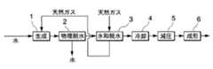
図1は、本発明に係るガスハイドレートスラリーの脱水装置及びスラリー脱水方法が適用される、天然ガスハイドレートの生成システムのプロセスを示すブロック図である。
図において、図中の符号1は天然ガスと水とを氷点よりも高温かつ大気圧よりも高圧下で反応させて天然ガスハイドレートを生成する生成手段、2は生成された天然ガスハイドレートを物理的に脱水する物理脱水手段、3は脱水の過程もしくは脱水後において天然ガスハイドレートに含まれる残存水分を天然ガスと反応させて天然ガスハイドレートを生成する水和脱水手段、4は生成された天然ガスハイドレートを冷却する冷却手段、5は冷却された天然ガスハイドレートを大気圧まで減圧する減圧手段、6は天然ガスハイドレートを成形固化する成形手段である。
【0019】
当該生成システムの具体的な装置構成を図2に示す。図において、図中の符号11は生成手段1を構成する生成反応装置、12は物理脱水手段2を構成するガスハイドレートスラリーの脱水装置となるスクリュープレス型脱水装置、13は水和脱水手段3を構成する2軸スクリュー型脱水装置、14は冷却手段4を構成するスクリューコンベア型冷却装置、15は減圧手段5を構成するバルブ切替型減圧装置、16は成形手段6を構成する加圧プレス型成形装置(ガスハイドレート成形装置)である。また、符号17は原料である水を貯蔵する貯水槽、18は同じく原料である天然ガスを産出するガス田、19はガス田18から産出された天然ガスを貯蔵するガス貯蔵部である。
【0020】
生成反応装置11は密閉された圧力容器20を有している。圧力容器20には水配管21を介して貯水槽17が接続されており、圧力容器20の内部には、水配管21を通じて貯水槽17の水が供給されることによって水相Lが形成されている。また、水配管21には給水ポンプ22およびバルブ23が設けられており、水相Lが所定の水位を保つように制御される。
【0021】
また、圧力容器20にはガス配管24を介してガス貯蔵部19が接続されている。ガス貯蔵部19には、ガス田18から産出された天然ガスが、酸性ガスおよび重質成分の除去の工程を経た後、圧縮機等により低温・高圧の状態にされて貯蔵されている。圧力容器20の内部には、ガス貯蔵部19に貯蔵された天然ガスがガス配管24を通じて供給されることによって気相Gが形成されている。
【0022】
さらに、圧力容器20には気相Gの圧力を計測する圧力計25が設けられ、ガス配管にはバルブ26および流量調節弁27が設けられており、流量調節弁27の開度は、圧力計25の計測値に基づき圧力容器20内部に天然ガスを補充して気相Gの圧力をガスハイドレートの生成圧力(例えば40atm)に保つように制御される。
【0023】
圧力容器20の内部には、水相Lの温度を氷点よりも高温であってガスハイドレートの生成温度(例えば5℃前後)よりも低温(これの状態を「過冷却」と定義する)に保つ冷却装置28が設けられている。冷却装置28によって過冷却の状態を保つのは、天然ガスハイドレートが生成する過程で発生する水和熱を回収し、生成反応装置11の内部を常に生成温度に保つためである。なお、冷却装置28には、水相Lを直接冷却する冷却コイルやラジエタ、圧力容器20を包んで容器全体を冷却する冷却ジャケットを採用するのが好ましい。
【0024】
圧力容器20には、底部と頂部とを繋ぐ水配管30が接続されている。水配管30には、フィルタ31、バルブ32、水循環ポンプ33、熱交換器34およびバルブ35が設けられている。また、圧力容器20の頂部から内側に突き出した水配管30の端部には、スプレーノズル36が設けられている。
【0025】
水相Lの液面に近い圧力容器20の側面には、液面に生成されたスラリー状の天然ガスハイドレートを抜き出すスラリー抜出口20aが設けられている。このスラリー抜出口20aはスラリー配管37を介してスクリュープレス型脱水装置12に接続されている。スラリー配管37には、バルブ38およびスラリー抜出ポンプ39が設けられており、水相Lの液面に生成された天然ガスハイドレートを抜き出してスクリュープレス型脱水装置12に供給するようになっている。
【0026】
スクリュープレス型脱水装置12は、円筒形の内部空間40aを有する容器本体40と、容器本体40の内部に設けられた筒形スクリーン(メッシュ)状のろ材40cと、側面に螺旋状の突条部41aを有し内部空間40aに配置された軸体であるスクリュー部41と、このスクリュー部41を駆動する駆動部42とを備えている。
容器本体40の先端(上流側)には、生成反応装置11においてスラリー状に生成された天然ガスハイドレート(原料スラリー)を上方から内部空間40aに取り入れる原料スラリー導入口40bが設けられている。原料スラリー導入口40bには、上述したスラリー配管37が接続されている。容器本体40は、内部空間40aを形成するろ材(内壁)40cと外殻を構成する筐体40dとの二重構造になっており、ろ材40cはメッシュ加工され、筐体40dの下部には脱水して内部に溜まった水(回収水)を排出する回収水排水口40eが設けられている。
【0027】
スクリュー部41は、突条部41aの回転外周面を内部空間40aの内面、すなわちろ材40cに近接させて配置されるとともに、自らの軸線を中心として所定方向に回転可能に支持されており、軸端に連結された駆動部42によって回転駆動される。
容器本体40の終端(下流側)には、スクリュー部41の回転によって搬送されてきた天然ガスハイドレートを取り出すハイドレート排出口40fが設けられている。ハイドレート排出口40fはハイドレート配管43を介して後段の2軸スクリュー型脱水装置13に接続されている。
【0028】
以下では、上述したスクリュープレス型脱水装置(ガスハイドレートスラリーの脱水装置)12について、本発明の特徴的な構成を詳述する。
図3は、図2のスクリュープレス型脱水装置12を拡大して、その詳細な構成を示したものである。
さて、このスクリュープレス型脱水装置12は、脱水する原料スラリーが天然ガスハイドレートであって、その回収率を確保するとともに含水率の低い最終製品を得るためにも、天然ガスハイドレートが分解せず、かつ、水が凝固しない条件下で脱水しなければならない。このため、圧力が0.5MPa以上といった高圧条件を維持した環境下で脱水する必要がある。なお、この場合の温度条件は、0℃となる。
【0029】
そこで、スクリュープレス型脱水装置12の容器本体40を上記高圧条件に耐えうる圧力容器とし、その内部にスクリュープレス型の脱水機を設置する。具体的には、外殻となる筐体40dを圧力容器とし、駆動部42にキャンドモータを使用したスクリュー部41を採用する。
駆動部42となるキャンドモータは、圧力容器である筐体40dの一部をなす外壁部42aの内壁面に固定側の胴体部コイル42bを備え、スクリュー部41の軸部を延長した軸端部41bに回転側のローター部コイル42cが設けられている。なお、胴体部コイル42bとローター部コイル42cとの間は、非接触に分離されている。
【0030】
このような構成としたので、ローター部コイル42cは、外壁部42aに固定されている胴体部コイル42bに対して、通電により同軸としたスクリュー部41と一体に回転する。このため、スクリュー部41及び駆動部42は、圧力容器の筐体40dを貫通する回転軸部をシールするというに、困難なシール構造が不要の設置構造となる。特に、可燃性ガスである天然ガスが回転軸の貫通部から容器本体40の外へ漏出することは絶対に避けなければならないので、軸貫通部における完全なシール構造が不要となるキャンドモータの採用は、この観点からも好ましいことである。
【0031】
上述したスクリュープレス型脱水装置12で脱水された天然ガスハイドレートは、2軸スクリュー型脱水装置13へ送られる。
2軸スクリュー型脱水装置13は、断面が長円形をなす筒形の内部空間50aを有する容器本体50と、側面に螺旋状の突条部51a,52aを有し内部空間50aに配置されて個々に回転しながら天然ガスハイドレートを搬送する2本の軸体51,52とを備えている。
【0032】
容器本体50の先端には、スクリュープレス型脱水装置12において物理的に脱水された天然ガスハイドレートを取り入れる取入口50bが設けられている。取入口50bには、上述したハイドレート配管43が接続されている。
軸体51,52は、両者が平行に配置されるとともに軸方向から見てそれぞれの突条部51a,52aを重複させて配置されている。さらに、それぞれの突条部51a,52aを内部空間50aの内面に近接させて配置されるとともに、自らの軸線を中心として回転可能に支持されており、駆動部53によって回転駆動される。なお、両軸体の回転方向は同方向であってもよいし、異なる方向であってもよい。
【0033】
容器本体50の終端には、軸体51,52の回転によって搬送されてきたガスハイドレートを取り出す取出口50cが設けられている。取出口50cにはハイドレート配管54を介して後段のスクリューコンベア型冷却装置14に接続されている。
取出口50cに近い容器体50の側面には、天然ガスを内部空間50aに供給するガス供給孔50dが設けられている。ガス供給孔50dは、ガス配管24から分岐するガス配管55を介してガス貯蔵部19に接続されている。ガス配管55にはバルブ56および流量調節弁57が設けられている。
【0034】
一方、取入口50bに近い容器体50には、内部空間50aの圧力を検出する圧力計58が設置されており、流量調節弁57の開度は、圧力計58の計測値に基づき内部空間50aに天然ガスを補充して内部の圧力を常に生成圧(例えば40atm)に保持するように制御されている。
【0035】
スクリュープレス型脱水装置12および2軸スクリュー型脱水装置13には、容器本体40,50の内部を上記過冷却の状態に保持する冷却装置(図示略)が設けられている。
【0036】
スクリューコンベア型冷却装置14は、円筒形の内部空間60aを有する容器本体60と、側面に螺旋状の突条部61aを有し内部空間60aに配置された軸体61とを備えている。
容器本体60の先端には、2軸スクリュー型脱水装置13において水和脱水された天然ガスハイドレートを内部空間60aに取り入れる取入口60bが設けられている。取入口60bには、上述したハイドレート配管54が接続されている。
【0037】
軸体61は、突条部61aを内部空間60aの内面に近接させて配置されるとともに、自らの軸線を中心として所定方向に回転可能に支持されており、駆動部62によって回転駆動される。
容器体60の終端には、軸体61の回転によって搬送されてきた天然ガスハイドレートを取り出す取出口60cが設けられている。取出口60cはハイドレート配管63を介して後段のバルブ切替型減圧装置15に接続されている。
【0038】
容器本体60は、内部空間60aを形成する内壁60dと外殻を構成する筐体60eとの二重構造になっており、取出口60cに近い筐体60eの側面には内壁60dとの隙間に冷媒を導入する冷媒入口60fが設けられ、取入口60bに近い筐体60eの側面には冷媒を導出する冷媒出口60gが設けられている。
容器本体60には、冷媒入口60fと冷媒出口60gとを繋ぐ冷媒配管65が接続されており、冷媒配管65には冷媒循環ポンプ66および熱交換器67が設けられている。冷媒は熱交換器66によって冷却され、冷媒配管65を通じて内壁60dと筐体60eとの隙間に流入し、脱水を終えた天然ガスハイドレートを低気圧下でも分解しない氷点以下の低温(例えば−10℃〜−15℃)まで冷却する。
【0039】
バルブ切替型減圧装置15は、ハイドレート配管63に直列に設けられた2つのバルブ71,72によって構成されている。2つのバルブ71,72は離間して配置され、後段のバルブ72を経たハイドレート配管63は大気開放されており、その後段には加圧プレス型成形装置16が設けられている。加圧プレス型成形装置16は、固定の壁部75と壁部75に接近離間可能に駆動されるプレート76とを備えている。
【0040】
上記のように構成された生成システムによる天然ガスハイドレートの生成について説明する。
まず、貯水槽17から圧力容器20内に水を導入し水相Lを形成する。同時に、ガス貯蔵部19から圧力容器20内に天然ガスを導入し、気相Gの圧力をガスハイドレートの生成圧力にまで高める。なお、水相Lを形成する水には、必要であれば安定化剤を添加してもよい。次に、水相Lの温度を過冷却の状態にまで冷却し、以後はこの状態が維持されるように温度管理を行う。
【0041】
圧力容器20内の温度および圧力の状態が安定したら、水相Lを形成する水の一部を水配管30を通じて圧力容器20の底部から抜き出し、熱交換器34によって上記再度冷却した後、スプレーノズル36から気相G中に噴霧する。スプレーノズル36から噴霧された水粒子は気相G中を漂いながら水相Lに向けて落下する。このように気相G中に水の粒子を多量に形成することにより、気相G中に存在する水の粒子の表面積、すなわち気相Gを形成する天然ガスとの接触面積が極めて大きくなる。水粒子の表面では、水と天然ガスとの水和反応が起こり、天然ガスハイドレートが生成される。なお、圧力容器20内の温度は氷点よりも高温になるように制御されているので、水相Lを形成する水や噴霧された水粒子が凍りつくことはない。
【0042】
水粒子の表面で生成された天然ガスハイドレートはそのまま落下し、水相Lの液面に降り積もり、天然ガスハイドレートの層を形成する。この天然ガスハイドレートはスラリー抜出口20aから抜き出され、スラリー配管37を通じてスクリュープレス型脱水装置12に送り込まれる。このとき、天然ガスハイドレートは水とともに回収されるため、含水率が非常に高いスラリー状となる。
【0043】
スラリー配管37を通じてスクリュープレス型脱水装置12に送り込まれたスラリー状天然ガスハイドレート(原料スラリー)は、原料スラリー導入口40bから容器本体40の内部空間40aに落下して内部空間40aに収容される。そして、スクリュー部41の回転によって軸方向に搬送され、その過程で加圧されることによって物理的に脱水される。この時、スクリュー部41が設置されている容器本体40内は適切な高圧及び温度に維持されているので、天然ガスハイドレートは分解することなく脱水される。また、水分についても、凝固して氷になるようなことはないので、液体のまま効率よく脱水されて回収される。従って、前工程でせっかく生成した天然ガスハイドレートが分解し、回収率を低下させるようなことはない。
なお、天然ガスハイドレートから分離された水分は、ろ材40cのメッシュを通じて筐体40dの下部に落下して集められ、回収水排出口40eから排出される。
【0044】
一方、物理脱水を終えた天然ガスハイドレートは、ハイドレート排出口40fを通じてスクリュープレス型脱水装置12から取り出され、ハイドレート配管43を通じて2軸スクリュー型脱水装置13に送り込まれる。
2軸スクリュー型脱水装置13に送り込まれた天然ガスハイドレートは、取入口50bを通じて内部空間50aに収容され、軸体51,52の回転によって軸方向に搬送される。その過程で残存する水分と内部空間50aに供給された天然ガスと接触し、これとともに撹拌されつつ冷却されることによって残存する水分と天然ガスとを反応させてハイドレート化する。
【0045】
内部空間50aに収容された天然ガスハイドレートは、取出口50cに至るころには残存する水分のほとんどを未水和の天然ガスと水和反応させることで脱水され、結果的に天然ガスハイドレートそのものの量を増加させる。水和脱水を終えた天然ガスハイドレートは、取出口50Cを通じて2軸スクリュー型脱水装置13から取り出され、ハイドレート配管54を通じてスクリューコンベア型冷却装置14に送り込まれる。
【0046】
スクリューコンベア型冷却装置14に送り込まれた天然ガスハイドレートは、取入口60bを通じて内部空間60aに収容され、軸体41の回転によって軸方向に搬送され、その過程で容器本体60内部を循環する冷媒によって冷却される。氷点以下の低温になるまで冷却された天然ガスハイドレートは、取出口60fを通じてスクリューコンベア型冷却装置14から取り出され、ハイドレート配管63を通じてバルブ切替型減圧装置15に送り込まれる。
【0047】
バルブ切替型減圧装置15は上流側のバルブ71を開き、下流側のバルブ72を閉じた状態とされ、天然ガスハイドレートを受け入れる。バルブ71,72間には天然ガスハイドレートが蓄積していくので、ある程度になったらバルブ71を閉じ、続いてバルブ72を開いてバルブ71,72間の天然ガスハイドレートを大気圧まで減圧する。減圧を終えた天然ガスハイドレートは、バルブ切替型減圧装置15から取り出され、加圧プレス型成形装置16に送り込まれる。
【0048】
加圧プレス型成形装置16に送り込まれた天然ガスハイドレートは、プレート76によって壁部75に押し付けられるようにして成形固化される。成形固化された天然ガスハイドレートは図示しない専用の輸送容器に収容され、貯蔵・輸送される。
【0049】
上記の生成システムにおいては、天然ガスと水とを氷点よりも高温、かつ大気圧よりも高圧下で反応させることで、水を凍らせることなく天然ガスハイドレートを生成することが可能である。ただし、この天然ガスハイドレートには多量の水が含まれることになるので、生成された天然ガスハイドレートを物理的に脱水し、さらにこの物理脱水の後に天然ガスハイドレートに含まれる残存水分を天然ガスと反応させて天然ガスハイドレートを生成することによって天然ガスハイドレートの含水率を低下させる。
【0050】
ここまでの工程はいずれも氷点よりも高温、かつ大気圧よりも高圧下で実施されるので、生成された天然ガスハイドレートを大気圧下に取り出すべく、これを氷点よりも低温にまで冷却し、残存する水(氷)の中に凍りづけにしたのち減圧し、大気圧下に取り出せるようにする。
以上の各工程を実施することで、より含水率の低い天然ガスハイドレートが得られる。
【0051】
従って、上記の生成システムによれば、含水率の低い天然ガスハイドレートを生成してその貯蔵や輸送にかかるコストを削減することができる。また、減圧を終えた天然ガスハイドレートを成形固化することにより、貯蔵や輸送の際の利便性を向上させることができる。
【0052】
なお、本実施形態においては、物理脱水単独のスクリュープレス型脱水装置12により脱水した後に水和脱水を行っているが、物理脱水と同時進行的に水和脱水を行うようにしても構わない。また、減圧手段5(バルブ切替型減圧装置15)の後段に成形手段6(加圧プレス型成形装置16)を設けたが、成形手段6を設けず、脱水を終えた天然ガスハイドレートをそのまま容器に詰めて貯蔵・輸送することも可能である。
【0053】
ところで、上述したスクリュープレス型脱水装置12は、図1に示した生成システムのプロセス以外にも使用することができる。
以下、上述したスクリュープレス型脱水装置12を適用できるプロセスの構成例を図面に基づいて簡単に説明する。なお、上記実施形態において既に説明した構成要素には同一符号を付して説明は省略する。
図4に示すブロック図のプロセス構成(第1変形例)では、脱水によって分離された水(回収水)を生成手段1に戻して再利用する。具体的には、スクリュープレス型脱水装置12の排水口40eと貯水槽17とを接続する水配管を設け、天然ガスハイドレートから分離された回収水を、この水配管を通じて貯水槽17や圧力容器20に戻すように構成されている。
【0054】
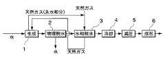
図5に示すブロック図のプロセス構成(第2変形例)では、図4の場合と同様に、回収水を生成手段1に戻すのであるが、回収水を生成手段1に戻す前にその水を冷却する水冷却手段7を設けてある。
【0055】
図6に示すブロック図のプロセス構成(第3変形例)では、水和脱水手段3において天然ガスハイドレートの生成に供されなかった天然ガスを生成手段1に導くようにしてある。
【0056】
図7に示すブロック図のプロセス構成(第4変形例)では、図6の場合と同様に、天然ガスを生成手段1に導入する前に冷却する、天然ガス冷却手段8を設けてある。
なお、天然ガス冷却手段8には、天然ガスを直接的に冷却する機構の他、天然ガスを断熱膨張させ自らの温度を低下させたうえで昇圧する機構を採用しても構わない。
また、生成手段1への導入前ではなく、天然ガスを水和脱水手段3へ導入する前に天然ガス冷却手段8を設けても構わないし、両方に設けても構わない。
【0057】
図8に示すブロック図のプロセス構成(第5変形例)では、生成手段1において天然ガスハイドレートの生成に供されなかった天然ガスを水和脱水手段3に導き、生成手段1と水和脱水手段3との間を循環させるようにしてある。
【0058】
図9に示すブロック図のプロセス構成(第6変形例)では、生成手段1において天然ガスハイドレートを生成した後に残る未反応ガスを生成手段1から除去する(パージする)ようにしてある。
なお、図8に示すように、天然ガスを生成手段1と水和脱水手段3との間で循環させる場合には、循環系を構成するガス配管のいずれかの場所から未反応ガスを除去するようにしても構わない。
【0059】
図10に示すブロック図のプロセス構成(第7変形例)では、未反応ガスを内燃機関9やボイラ等の燃料として利用している。
【0060】
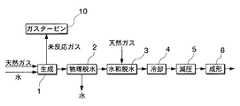
図11に示すブロック図のプロセス構成(第8変形例)では、未反応ガスをガスタービン10の駆動ガスとして利用している。
【0061】
以上説明したように、本発明のスクリュープレス型脱水装置は、図1及び図4〜11に示したブロック図のプロセス構成はもちろんのこと、それらの組合せによるプロセス構成に対しても採用可能である。
また、本発明のスクリュープレス型脱水装置は、上記の各プロセス構成またはそれらの組合せによるプロセス構成を採用した天然ガスハイドレート生成システムに限らず、生成後の天然ガスハイドレートについて脱水を必要とするプロセスを採用した生成システムに対しても採用可能である。
さらに、上記の説明では天然ガスハイドレートを例に示してあるが、本発明はこれに限定されるものではなく、天然ガスハイドレート以外のガスハイドレートにも適用することができる。
【0062】
なお、本発明の構成は上述した実施形態に限定されるものではなく、本発明の要旨を逸脱しない範囲内において適宜変更することができる。
【0063】
【発明の効果】
上述した本発明のガスハイドレートスラリー脱水装置によれば、下記のような効果を奏する。
請求項1に記載のガスハイドレートスラリーの脱水装置によれば、ガスハイドレートが分解せず、かつ、水が凝固しない温度及び圧力条件を維持した圧力容器内に脱水手段を設置し、前記脱水手段が、円筒形の内部空間を有する前記圧力容器の容器本体と、該容器本体の内部に設けられた筒形スクリーン状のろ材と、側面に螺旋状の突条部を有し前記内部空間に配置された軸体であるスクリュー部と、該スクリュー部を駆動する駆動部とを備えたスクリュープレス型であるから、脱水中にガスハイドレートを分解させることがなく、また、水が液体のまま凝固することもない。従って、原料スラリーの水を容易に脱水することができ、しかも、高い回収率を維持したガスハイドレートスラリーの脱水装置を提供することができる。
【0064】
また、本発明のガスハイドレートスラリーの脱水装置は、脱水手段としてスクリュープレス型を採用したことで連続脱水が可能となり、前記脱水手段を圧力容器内に設置、特にキャンドモータを採用して駆動することで、圧力容器を貫通する軸部分がなくなって軸シールが不要となる。
このような脱水装置は、ガスハイドレートが分解せず、かつ、水が凝固しない環境とするため高圧条件が求められ、しかも、分解すると可燃性ガスとなるため漏洩を確実に防止することが求められる天然ガスハイドレートの脱水に特に適している。
【0065】
請求項5に記載の発明によれば、ガスハイドレートが分解せず、かつ、水が凝固しない温度及び圧力条件に維持した圧力容器内に設置されている脱水手段に水中にガスハイドレートが分散したスラリーを供給して脱水し、前記脱水手段として、円筒形の内部空間を有する前記圧力容器の容器本体と、該容器本体の内部に設けられた筒形スクリーン状のろ材と、側面に螺旋状の突条部を有し前記内部空間に配置された軸体であるスクリュー部と、該スクリュー部を駆動する駆動部とを備えたスクリュープレス型が用いられるガスハイドレートスラリーの脱水方法としたので、脱水中にガスハイドレートを分解させることがなく、また、水が液体のまま凝固することもない。従って、原料スラリーの水を容易に脱水することができ、しかも、高い回収率を維持したガスハイドレートスラリーの脱水方法を提供することができる。
【0066】
また、本発明のガスハイドレートスラリーの脱水方法は、脱水手段としてスクリュープレス型を採用したことで連続脱水が可能となり、前記脱水手段を圧力容器内に設置、特にキャンドモータを採用して駆動することで、圧力容器を貫通する軸部分がなくなって軸シールが不要となる。
このような脱水方法は、ガスハイドレートが分解せず、かつ、水が凝固しない環境とするため高圧条件が求められ、しかも、分解すると可燃性ガスとなるため漏洩を確実に防止することが求められる天然ガスハイドレートの脱水に特に適している。
【図面の簡単な説明】
【図1】 本発明に係る実施形態として、天然ガスハイドレート生成システムのプロセス構成例を示すブロック図である。
【図2】 図1の生成システムの具体的な装置構成を示す図である。
【図3】 本発明に係るガスハイドレートスラリーの脱水装置の一実施形態を示す構成図である。
【図4】 本発明に係るガスハイドレートスラリーの脱水装置を適用可能な天然ガスハイドレート生成システムのプロセス(第1変形例)を示すブロック図である。
【図5】 本発明に係るガスハイドレートスラリーの脱水装置を適用可能な天然ガスハイドレート生成システムのプロセス(第2変形例)を示すブロック図である。
【図6】 本発明に係るガスハイドレートスラリーの脱水装置を適用可能な天然ガスハイドレート生成システムのプロセス(第3変形例)を示すブロック図である。
【図7】 本発明に係るガスハイドレートスラリーの脱水装置を適用可能な天然ガスハイドレート生成システムのプロセス(第4変形例)を示すブロック図である。
【図8】 本発明に係るガスハイドレートスラリーの脱水装置を適用可能な天然ガスハイドレート生成システムのプロセス(第5変形例)を示すブロック図である。
【図9】 本発明に係るガスハイドレートスラリーの脱水装置を適用可能な天然ガスハイドレート生成システムのプロセス(第6変形例)を示すブロック図である。
【図10】 本発明に係るガスハイドレートスラリーの脱水装置を適用可能な天然ガスハイドレート生成システムのプロセス(第7変形例)を示すブロック図である。
【図11】 本発明に係るガスハイドレートスラリーの脱水装置を適用可能な天然ガスハイドレート生成システムのプロセス(第8変形例)を示すブロック図である。
【符号の説明】
12 スクリュープレス型脱水装置
(ガスハイドレートスラリーの脱水装置)
40 容器本体
40b 原料スラリー導入口
40c ろ材
40d 筐体
40e 回収水排水口
40f ハイドレート排出口
41 スクリュー部
41a 突条部
41b 軸端部
42 駆動部(キャンドモータ)
42a 外壁部
42b 胴体部コイル
42c ローター部コイル[0001]
BACKGROUND OF THE INVENTION
The present invention relates to a dehydration apparatus and dehydration method for a gas hydrate slurry, in which water is removed from a slurry in which a gas hydrate (hydrate) generated by bringing a raw material gas into contact with water is dispersed in water.
[0002]
[Prior art]
At present, natural gas mainly composed of hydrocarbons such as methane is stored and transported by collecting natural gas from a gas field, cooling it to the liquefaction temperature, and storing and transporting it as liquefied natural gas (LNG). The method of transport is common. However, for example, in the case of methane, which is the main component of liquefied natural gas, an extremely low temperature condition of −162 ° C. is necessary for liquefaction, and in order to perform storage and transportation while maintaining such conditions, a dedicated storage device And special transport means such as LNG transport ships.
Since the manufacturing, maintenance and management of such devices and the like require a very high cost, a low-cost storage / transport method alternative to the above method has been intensively studied.
[0003]
As a result of such research, a method has been found in which natural gas is hydrated to produce a solid state hydrate (hereinafter referred to as “natural gas hydrate”) and stored and transported in this solid state. Especially promising. This method does not require cryogenic conditions as in the case of handling LNG, and is relatively easy to handle because it is solid. For this reason, the existing refrigeration apparatus or a slightly improved version of the existing container ship can be used as a storage apparatus or a transportation means, respectively. Therefore, it is expected that the cost can be greatly reduced.
[0004]
This natural gas hydrate is a kind of clathrate compound (clathrate compound), and in a three-dimensional cage clathrate (clathrate) formed by a plurality of water molecules (H2 O), It has a crystal structure in which molecules constituting each component of natural gas, that is, methane (CH4 ), ethane (C2 H6 ), propane (C3 H8 ), etc. enter and are included. The intermolecular distance between the natural gas constituent molecules included in the clathrate is shorter than the intermolecular distance in the gas cylinder when the natural gas is filled with high pressure. This means that natural gas can produce a tightly packed solid. For example, under conditions where hydrates of methane can exist stably, that is, at -30 ° C. and atmospheric pressure (1 kg / cm2 ). The volume can be about 1/170 compared to the gas state. Thus, natural gas hydrate can be produced under conditions of temperature and pressure that can be obtained relatively easily, and can be stably stored.
[0005]
In this method, the natural gas produced from the gas field is stored in a low temperature / high pressure state by removing acidic gases such as carbon dioxide (CO2 ) and hydrogen sulfide (H2 S) in the acidic gas removal step. And then hydrated in the production process. This natural gas hydrate is in the form of a slurry in which water is mixed (hereinafter referred to as “raw slurry”). In the subsequent dehydration step, unreacted water mixed in the raw slurry is removed, and further a cooling step and a decompression step. The product that has become solid after passing through is sealed in a container such as a container, and stored in a storage device in a state adjusted to a predetermined temperature and pressure.
[0006]
At the time of transportation, the container is loaded on a transportation means such as a container ship and transported to a destination. After landing at the destination, the natural gas hydrate is returned to the natural gas state through the decomposition process and sent to each supply area.
In addition to the natural gas hydrate described above, various gas hydrates can be generated by replacing the raw material gas.
[0007]
[Problems to be solved by the invention]
By the way, in the process from the production | generation of the conventional gas hydrate mentioned above to transport, there exist the following problems which should be solved.
That is, in the gas hydrate production plant, since the gas hydrate immediately after production is in a slurry state containing a large amount of water (water slurry), if this gas hydrate is stored or transported as it is or frozen, Since the volume and weight increase by the amount of water (ice), the cost for storage and transportation becomes enormous. In other words, if the slurry-like gas hydrate (raw material slurry) containing a large amount of water is cooled, the gas density when transported as a gas hydrate solid will be reduced, and excess water (ice) will be transported at the same time. It is not preferable in terms of transportation efficiency.
[0008]
In particular, in the case of natural gas hydrate using natural gas as a raw material, in order to ensure a high recovery rate, dehydration is performed under conditions where natural gas hydrate does not decompose and water does not become ice. Therefore, it is desirable to dehydrate while maintaining high pressure conditions. Further, since natural gas is a flammable gas, it is important to completely eliminate leakage to the outside of the dehydrator.
The present invention has been made in view of the above circumstances, and under conditions where gas hydrate does not decompose and water does not solidify and become ice, it is continuously and efficiently dehydrated and has a low water content. An object of the present invention is to provide a gas hydrate slurry dewatering apparatus and slurry dewatering method that can provide gas hydrate.
[0009]
[Means for Solving the Problems]
The present invention employs the following means in order to solve the above problems.
The gas hydrate slurry dewatering device according to
[0010]
With such a gas hydrate slurry dehydrating apparatus, the dehydrating means is installedin apressure vessel that maintains the temperature and pressure conditions in which the gas hydrate does not decompose and water does not solidify, and thedehydrating means comprises: A container main body of the pressure vessel having a cylindrical inner space, a cylindrical screen-shaped filter medium provided inside the container main body, and a spiral protrusion on the side surface are disposed in the inner space. Since it is a screw press type | mold provided with the screw part which is a shaft body, and the drive part which drives this screw part , liquid water can be easily dehydrated without decomposing | disassembling gas hydrate.
[0012]
In the gas hydrate slurry dehydrating apparatus according to the present invention, the driving portion of the dehydrating unit is not transmitted through the pressure vessel by installing the driving unit of the dehydrating unit in the pressure vessel. Is no longer necessary. The shaft seal is likely to cause leakage from the inside of the pressure vessel, and the leakage of the fluid inside the pressure vessel can be minimized by eliminating the shaft seal.
In particular, the shaft seal can be easily eliminated by driving the dehydrating means with a canned motor.
The above-described gas hydrate slurry dewatering apparatus is particularly suitable as a natural gas hydrate dewatering apparatus.
[0013]
The gas hydrate slurry dewatering method according to
[0014]
According to such a gas hydrate slurry dewatering method, the gas hydrate is submerged in the dewatering means installed in apressure vessel maintained at a temperature and pressure condition in which the gas hydrate is not decomposed and water does not solidify. The slurry in which the rate is dispersed is supplied and dehydrated, andas the dehydrating means, a container body of the pressure vessel having a cylindrical inner space, a cylindrical screen-shaped filter medium provided inside the container body, and a side surface Since a screw press mold having a screw portion which is a shaft body having a spiral ridge portion and disposed in the internal space and a drive portion for driving the screw portion is used, a gas hydrateis used. Liquid water can be easily dehydrated without decomposing water.
[0016]
In the gas hydrate slurry dehydrating method of the present invention, the driving force of the dehydrating means is not transmitted through the pressure vessel by installing the driving portion of the dehydrating means in the pressure vessel. Is no longer necessary. The shaft seal is likely to cause leakage from the inside of the pressure vessel, and the leakage of the fluid inside the pressure vessel can be minimized by eliminating the shaft seal.
In particular, the shaft seal can be easily eliminated by driving the dehydrating means with a canned motor.
The above-described method for dehydrating a gas hydrate slurry is particularly suitable as a method for dehydrating natural gas hydrate.
[0017]
DETAILED DESCRIPTION OF THE INVENTION
Hereinafter, an embodiment of a dehydration apparatus and dehydration method for a gas hydrate slurry according to the present invention will be described with reference to the drawings. In the following embodiments, the case where the gas hydrate is natural gas hydrate using natural gas as a raw material will be described.
[0018]
FIG. 1 is a block diagram showing a process of a natural gas hydrate generation system to which a gas hydrate slurry dewatering apparatus and slurry dewatering method according to the present invention is applied.
In the figure,
[0019]
A specific device configuration of the generation system is shown in FIG. In the figure,
[0020]
The
[0021]
In addition, a
[0022]
Further, the
[0023]
Inside the
[0024]
A
[0025]
On the side surface of the
[0026]
The screw
At the front end (upstream side) of the container
[0027]
The
At the terminal end (downstream side) of the container
[0028]
Below, the characteristic structure of this invention is explained in full detail about the screw press type | mold dehydration apparatus (dehydration apparatus of gas hydrate slurry) 12 mentioned above.
FIG. 3 is an enlarged view of the screw press
In this screw
[0029]
Therefore, the container
The canned motor serving as the
[0030]
Since it was set as such a structure, the
[0031]
The natural gas hydrate dehydrated by the screw
The biaxial screw-
[0032]
An
The
[0033]
At the end of the container
A
[0034]
On the other hand, a
[0035]
The screw
[0036]
The screw conveyor
At the tip of the container
[0037]
The
At the end of the
[0038]
The container
A
[0039]
The valve switching
[0040]
The production | generation of the natural gas hydrate by the production | generation system comprised as mentioned above is demonstrated.
First, water is introduced from the water storage tank 17 into the
[0041]
When the temperature and pressure in the
[0042]
The natural gas hydrate generated on the surface of the water particles falls as it is and falls on the liquid surface of the water phase L to form a natural gas hydrate layer. The natural gas hydrate is extracted from the
[0043]
Slurry natural gas hydrate (raw material slurry) sent to the screw
In addition, the water | moisture content isolate | separated from the natural gas hydrate is dropped and collected by the lower part of the housing | casing 40d through the mesh of the
[0044]
On the other hand, the natural gas hydrate that has been subjected to physical dehydration is taken out from the
The natural gas hydrate fed into the twin-
[0045]
The natural gas hydrate accommodated in the
[0046]
The natural gas hydrate fed into the screw conveyor
[0047]
The valve-switching
[0048]
The natural gas hydrate fed into the pressure press
[0049]
In the production system described above, natural gas hydrate can be produced without freezing water by reacting natural gas and water at a temperature higher than the freezing point and higher than atmospheric pressure. However, since this natural gas hydrate contains a large amount of water, the generated natural gas hydrate is physically dehydrated, and after this physical dehydration, the residual moisture contained in the natural gas hydrate is reduced. The moisture content of natural gas hydrate is reduced by reacting with natural gas to produce natural gas hydrate.
[0050]
Since all the steps up to here are performed at a temperature higher than the freezing point and higher than the atmospheric pressure, the generated natural gas hydrate is cooled to a temperature lower than the freezing point in order to take out the generated natural gas hydrate under the atmospheric pressure. After freezing in the remaining water (ice), the pressure is reduced so that it can be taken out under atmospheric pressure.
By carrying out the above steps, a natural gas hydrate having a lower moisture content can be obtained.
[0051]
Therefore, according to said production | generation system, the natural gas hydrate with a low moisture content can be produced | generated, and the cost concerning the storage or transportation can be reduced. Moreover, the convenience at the time of storage or transportation can be improved by molding and solidifying the natural gas hydrate after the decompression.
[0052]
In this embodiment, hydration dehydration is performed after dehydration by the screw
[0053]
By the way, the screw press type |
Hereinafter, a configuration example of a process to which the above-described screw
In the process configuration of the block diagram shown in FIG. 4 (first modification), the water separated by dehydration (recovered water) is returned to the generating means 1 and reused. Specifically, a water pipe for connecting the
[0054]
In the process configuration (second modified example) of the block diagram shown in FIG. 5, the recovered water is returned to the generating means 1 as in the case of FIG. 4, but before the recovered water is returned to the generating means 1, the water is Water cooling means 7 for cooling is provided.
[0055]
In the process configuration (third modified example) of the block diagram shown in FIG. 6, natural gas that has not been used for generating natural gas hydrate in the
[0056]
In the process configuration (fourth modified example) of the block diagram shown in FIG. 7, the natural gas cooling means 8 for cooling the natural gas before introducing it into the generating means 1 is provided as in the case of FIG. 6.
The natural gas cooling means 8 may employ a mechanism for boosting the natural gas by adiabatically expanding the natural gas and lowering its own temperature in addition to a mechanism for directly cooling the natural gas.
Further, the natural gas cooling means 8 may be provided before the natural gas is introduced into the hydration dehydration means 3 instead of being introduced into the generating means 1 or may be provided in both.
[0057]
In the process configuration of the block diagram shown in FIG. 8 (fifth modified example), the natural gas that has not been used for the production of natural gas hydrate in the production means 1 is guided to the hydration dehydration means 3, and Circulation with the
[0058]
In the process configuration of the block diagram shown in FIG. 9 (sixth modified example), the unreacted gas remaining after the natural gas hydrate is generated in the
In addition, as shown in FIG. 8, when natural gas is circulated between the production | generation means 1 and the hydration dehydration means 3, unreacted gas is removed from any place of the gas piping which comprises a circulation system. It doesn't matter if you do.
[0059]
In the process configuration (seventh modified example) in the block diagram shown in FIG. 10, the unreacted gas is used as fuel for the
[0060]
In the process configuration (eighth modification) of the block diagram shown in FIG. 11, unreacted gas is used as the driving gas for the
[0061]
As described above, the screw press-type dewatering device of the present invention can be applied not only to the process configuration of the block diagram shown in FIG. 1 and FIGS. .
Further, the screw press type dehydrator of the present invention is not limited to the natural gas hydrate generation system adopting the process configuration by the above-described process configurations or combinations thereof, and requires dehydration of the natural gas hydrate after generation. It can also be used for generation systems that employ processes.
Furthermore, in the above description, natural gas hydrate is shown as an example. However, the present invention is not limited to this and can be applied to gas hydrates other than natural gas hydrate.
[0062]
In addition, the structure of this invention is not limited to embodiment mentioned above, In the range which does not deviate from the summary of this invention, it can change suitably.
[0063]
【Effect of the invention】
The above-described gas hydrate slurry dewatering device of the present invention has the following effects.
According to the gas hydrateslurry dewatering apparatus according to
[0064]
In addition,the gas hydrate slurry dehydrating apparatus of thepresent invention can be continuously dehydrated by adopting a screw press type asthe dehydrating means, and the dehydrating means is installed in a pressure vessel, in particular driven by a canned motor. This eliminates the shaft portion penetrating the pressure vessel and eliminates the need for a shaft seal.
Such a dehydrator requires high-pressure conditions in order to create an environment in which the gas hydrate does not decompose and water does not solidify, and since it becomes a combustible gas when decomposed, it is required to reliably prevent leakage. Particularly suitable for the dehydration of natural gas hydrates.
[0065]
According to thefifth aspect of the present invention, the gas hydrate is dispersed in the water in the dehydrating means installed in thepressure vessel maintained at a temperature and pressure conditions in which the gas hydrate is not decomposed and water does not solidify. As thedehydrating means, a container body of the pressure vessel having a cylindrical inner space, a cylindrical screen-shaped filter medium provided inside the container body, and a spiral on the side surface Since a screw press die having a screw part that is a shaft body that is arranged in the internal space and a drive part that drives the screw part is used, the gas hydrate slurry isdehydrated . In addition, gas hydrate is not decomposed during dehydration, and water does not coagulate in a liquid state. Accordingly, it is possible to provide a method for dehydrating a gas hydrate slurry that can easily dehydrate the water of the raw slurry and that maintains a high recovery rate.
[0066]
Further,the gas hydrate slurry dehydration method of thepresent invention can be continuously dehydrated by adopting a screw press mold asthe dehydration means, and the dehydration means is installed in a pressure vessel, particularly driven by a canned motor. This eliminates the shaft portion penetrating the pressure vessel and eliminates the need for a shaft seal.
Such a dehydration method requires high-pressure conditions in order to create an environment in which the gas hydrate does not decompose and water does not solidify, and since it becomes a flammable gas when decomposed, it is required to reliably prevent leakage. Particularly suitable for the dehydration of natural gas hydrates.
[Brief description of the drawings]
FIG. 1 is a block diagram showing a process configuration example of a natural gas hydrate generation system as an embodiment according to the present invention.
FIG. 2 is a diagram illustrating a specific device configuration of the generation system of FIG. 1;
FIG. 3 is a configuration diagram showing an embodiment of a dehydration apparatus for gas hydrate slurry according to the present invention.
FIG. 4 is a block diagram showing a process (first modification) of a natural gas hydrate generation system to which the gas hydrate slurry dehydrating apparatus according to the present invention can be applied.
FIG. 5 is a block diagram showing a process (second modification) of a natural gas hydrate generation system to which the gas hydrate slurry dehydrating apparatus according to the present invention can be applied.
FIG. 6 is a block diagram showing a process (third modification) of a natural gas hydrate generation system to which the gas hydrate slurry dewatering apparatus according to the present invention can be applied.
FIG. 7 is a block diagram showing a process (fourth modification) of a natural gas hydrate generation system to which the gas hydrate slurry dewatering apparatus according to the present invention can be applied.
FIG. 8 is a block diagram showing a process (fifth modification) of a natural gas hydrate generation system to which the gas hydrate slurry dehydrating apparatus according to the present invention can be applied.
FIG. 9 is a block diagram showing a process (sixth modified example) of a natural gas hydrate generation system to which the gas hydrate slurry dewatering apparatus according to the present invention can be applied.
FIG. 10 is a block diagram showing a process (seventh modified example) of a natural gas hydrate generation system to which the gas hydrate slurry dewatering apparatus according to the present invention can be applied.
FIG. 11 is a block diagram showing a process (eighth modification) of a natural gas hydrate generation system to which the gas hydrate slurry dehydrating apparatus according to the present invention can be applied.
[Explanation of symbols]
12 Screw press type dehydrator (Gas hydrate slurry dehydrator)
40
42a
Claims (8)
Translated fromJapaneseガスハイドレートが分解せず、かつ、水が凝固しない温度及び圧力条件を維持した圧力容器内に脱水手段を設置し、
前記脱水手段が、円筒形の内部空間を有する前記圧力容器の容器本体と、該容器本体の内部に設けられた筒形スクリーン状のろ材と、側面に螺旋状の突条部を有し前記内部空間に配置された軸体であるスクリュー部と、該スクリュー部を駆動する駆動部とを備えたスクリュープレス型であることを特徴とするガスハイドレートスラリーの脱水装置。A gas hydrate slurry dewatering device for removing water from a slurry in which gas hydrate is dispersed in water,
A dehydrating means is installedin apressure vessel that maintains the temperature and pressure conditions in which gas hydrate does not decompose and water does not solidify.
The dehydrating means includes a container body of the pressure vessel having a cylindrical inner space, a cylindrical screen-shaped filter medium provided inside the container body, and a spiral protrusion on a side surface. An apparatus for dehydrating a gas hydrate slurry, comprisinga screw press type comprising a screw part that is a shaft body disposed in a space and a drive part that drives the screw part .
ガスハイドレートが分解せず、かつ、水が凝固しない温度及び圧力条件に維持した圧力容器内に設置されている脱水手段に水中にガスハイドレートが分散したスラリーを供給して脱水し、
前記脱水手段として、円筒形の内部空間を有する前記圧力容器の容器本体と、該容器本体の内部に設けられた筒形スクリーン状のろ材と、側面に螺旋状の突条部を有し前記内部空間に配置された軸体であるスクリュー部と、該スクリュー部を駆動する駆動部とを備えたスクリュープレス型が用いられることを特徴とするガスハイドレートスラリーの脱水方法。A method for dehydrating a gas hydrate slurry that removes water from a slurry in which gas hydrate is dispersed in water,
The slurry in which the gas hydrate is dispersed in water is supplied to a dehydration means installed in apressure vessel maintained at a temperature and pressure condition where the gas hydrate is not decomposed and water is not solidified, and dehydrated.
The dehydrating means includes a container body of the pressure vessel having a cylindrical inner space, a cylindrical screen-shaped filter medium provided inside the container body, and a spiral protrusion on a side surface. A method for dehydrating a gas hydrate slurry, wherein a screw press mold comprising a screw part which is a shaft body arranged in a space and a drive part for driving the screw part is used .
Priority Applications (5)
| Application Number | Priority Date | Filing Date | Title |
|---|---|---|---|
| JP2001264907AJP5019683B2 (en) | 2001-08-31 | 2001-08-31 | Gas hydrate slurry dewatering apparatus and method |
| US10/416,004US20040020123A1 (en) | 2001-08-31 | 2002-08-29 | Dewatering device and method for gas hydrate slurrys |
| PCT/JP2002/008724WO2003019068A2 (en) | 2001-08-31 | 2002-08-29 | Dewatering device and method for gas hydrate slurrys |
| EP02772823AEP1421313A2 (en) | 2001-08-31 | 2002-08-29 | Dewatering device and method for gas hydrate slurrys |
| NO20031894ANO20031894D0 (en) | 2001-08-31 | 2003-04-28 | Dewatering device and method for dewatering gas hydrate slurries |
Applications Claiming Priority (1)
| Application Number | Priority Date | Filing Date | Title |
|---|---|---|---|
| JP2001264907AJP5019683B2 (en) | 2001-08-31 | 2001-08-31 | Gas hydrate slurry dewatering apparatus and method |
Publications (2)
| Publication Number | Publication Date |
|---|---|
| JP2003073678A JP2003073678A (en) | 2003-03-12 |
| JP5019683B2true JP5019683B2 (en) | 2012-09-05 |
Family
ID=19091438
Family Applications (1)
| Application Number | Title | Priority Date | Filing Date |
|---|---|---|---|
| JP2001264907AExpired - Fee RelatedJP5019683B2 (en) | 2001-08-31 | 2001-08-31 | Gas hydrate slurry dewatering apparatus and method |
Country Status (5)
| Country | Link |
|---|---|
| US (1) | US20040020123A1 (en) |
| EP (1) | EP1421313A2 (en) |
| JP (1) | JP5019683B2 (en) |
| NO (1) | NO20031894D0 (en) |
| WO (1) | WO2003019068A2 (en) |
Families Citing this family (84)
| Publication number | Priority date | Publication date | Assignee | Title |
|---|---|---|---|---|
| KR100455839B1 (en) | 1999-11-26 | 2004-11-06 | 제이에프이 엔지니어링 가부시키가이샤 | Hydrate thermal storage medium and method for producing thereof, thermal storage apparatus using hydrate thermal storage medium, and hydrate cold thermal transportation medium |
| CA2410578A1 (en)* | 2001-03-29 | 2002-11-25 | Mitsubishi Heavy Industries, Ltd. | Gas hydrate production device and gas hydrate dehydrating device |
| JP5106727B2 (en)* | 2001-08-31 | 2012-12-26 | 三菱重工業株式会社 | Gas hydrate slurry dewatering equipment |
| WO2003102474A1 (en)* | 2002-05-31 | 2003-12-11 | Jfe Engineering Corporation | Hydrate slurry manufacturing device |
| JP4507534B2 (en)* | 2003-09-01 | 2010-07-21 | 株式会社Ihi | Method and apparatus for producing natural gas clathrate hydrate |
| JP4817608B2 (en)* | 2004-03-24 | 2011-11-16 | 三井造船株式会社 | Gas hydrate dispensing method and dispensing apparatus |
| JP4578916B2 (en)* | 2004-09-30 | 2010-11-10 | 三井造船株式会社 | Hydrate generator |
| JP2006104385A (en)* | 2004-10-07 | 2006-04-20 | Mitsui Eng & Shipbuild Co Ltd | Method for producing mixed gas hydrate |
| JP4564327B2 (en)* | 2004-10-18 | 2010-10-20 | 三井造船株式会社 | Gas hydrate dehydrator |
| JP2006111816A (en)* | 2004-10-18 | 2006-04-27 | Mitsui Eng & Shipbuild Co Ltd | Gas hydrate manufacturing method |
| JP2006117755A (en)* | 2004-10-20 | 2006-05-11 | Mitsui Eng & Shipbuild Co Ltd | High concentration gas hydrate generator and gas hydrate production plant using the device |
| JP4654010B2 (en)* | 2004-11-25 | 2011-03-16 | 三井造船株式会社 | Gas hydrate generator |
| US8114176B2 (en)* | 2005-10-12 | 2012-02-14 | Great Point Energy, Inc. | Catalytic steam gasification of petroleum coke to methane |
| EP2006362A4 (en)* | 2006-03-30 | 2010-11-10 | Mitsui Shipbuilding Eng | Process for producing gas hydrate pellet |
| US8043579B2 (en)* | 2006-04-05 | 2011-10-25 | Mitsui Engineering & Shipbuilding Co., Ltd. | Gas hydrate production apparatus and dewatering unit |
| US7922782B2 (en)* | 2006-06-01 | 2011-04-12 | Greatpoint Energy, Inc. | Catalytic steam gasification process with recovery and recycle of alkali metal compounds |
| KR101138096B1 (en)* | 2007-08-02 | 2012-04-25 | 그레이트포인트 에너지, 인크. | Catalyst-loaded coal compositions, methods of making and use |
| WO2009048723A2 (en)* | 2007-10-09 | 2009-04-16 | Greatpoint Energy, Inc. | Compositions for catalytic gasification of a petroleum coke and process for conversion thereof to methane |
| US20090090056A1 (en)* | 2007-10-09 | 2009-04-09 | Greatpoint Energy, Inc. | Compositions for Catalytic Gasification of a Petroleum Coke |
| CN101910373B (en)* | 2007-12-28 | 2013-07-24 | 格雷特波因特能源公司 | Catalytic gasification method for recovery of alkali metals from coke |
| WO2009086372A1 (en)* | 2007-12-28 | 2009-07-09 | Greatpoint Energy, Inc. | Carbonaceous fuels and processes for making and using them |
| US20090166588A1 (en)* | 2007-12-28 | 2009-07-02 | Greatpoint Energy, Inc. | Petroleum Coke Compositions for Catalytic Gasification |
| US20090165383A1 (en)* | 2007-12-28 | 2009-07-02 | Greatpoint Energy, Inc. | Catalytic Gasification Process with Recovery of Alkali Metal from Char |
| WO2009086370A2 (en)* | 2007-12-28 | 2009-07-09 | Greatpoint Energy, Inc. | Processes for making syngas-derived products |
| WO2009086367A1 (en)* | 2007-12-28 | 2009-07-09 | Greatpoint Energy, Inc. | Petroleum coke compositions for catalytic gasification and preparation process thereof |
| US20090165376A1 (en) | 2007-12-28 | 2009-07-02 | Greatpoint Energy, Inc. | Steam Generating Slurry Gasifier for the Catalytic Gasification of a Carbonaceous Feedstock |
| WO2009086363A1 (en)* | 2007-12-28 | 2009-07-09 | Greatpoint Energy, Inc. | Coal compositions for catalytic gasification and process for its preparation |
| KR101140542B1 (en)* | 2007-12-28 | 2012-05-22 | 그레이트포인트 에너지, 인크. | Catalytic gasification process with recovery of alkali metal from char |
| WO2009111331A2 (en) | 2008-02-29 | 2009-09-11 | Greatpoint Energy, Inc. | Steam generation processes utilizing biomass feedstocks |
| US7926750B2 (en) | 2008-02-29 | 2011-04-19 | Greatpoint Energy, Inc. | Compactor feeder |
| US20090220406A1 (en)* | 2008-02-29 | 2009-09-03 | Greatpoint Energy, Inc. | Selective Removal and Recovery of Acid Gases from Gasification Products |
| US20090260287A1 (en)* | 2008-02-29 | 2009-10-22 | Greatpoint Energy, Inc. | Process and Apparatus for the Separation of Methane from a Gas Stream |
| CA2716135C (en)* | 2008-02-29 | 2013-05-28 | Greatpoint Energy, Inc. | Particulate composition for gasification, preparation and continuous conversion thereof |
| US20090217575A1 (en)* | 2008-02-29 | 2009-09-03 | Greatpoint Energy, Inc. | Biomass Char Compositions for Catalytic Gasification |
| WO2009111345A2 (en) | 2008-02-29 | 2009-09-11 | Greatpoint Energy, Inc. | Catalytic gasification particulate compositions |
| US8286901B2 (en)* | 2008-02-29 | 2012-10-16 | Greatpoint Energy, Inc. | Coal compositions for catalytic gasification |
| US8114177B2 (en) | 2008-02-29 | 2012-02-14 | Greatpoint Energy, Inc. | Co-feed of biomass as source of makeup catalysts for catalytic coal gasification |
| US8297542B2 (en)* | 2008-02-29 | 2012-10-30 | Greatpoint Energy, Inc. | Coal compositions for catalytic gasification |
| US20090217582A1 (en)* | 2008-02-29 | 2009-09-03 | Greatpoint Energy, Inc. | Processes for Making Adsorbents and Processes for Removing Contaminants from Fluids Using Them |
| WO2009111332A2 (en)* | 2008-02-29 | 2009-09-11 | Greatpoint Energy, Inc. | Reduced carbon footprint steam generation processes |
| CN101981163B (en)* | 2008-04-01 | 2014-04-16 | 格雷特波因特能源公司 | Processes for the separation of methane from a gas stream |
| WO2009124019A2 (en) | 2008-04-01 | 2009-10-08 | Greatpoint Energy, Inc. | Sour shift process for the removal of carbon monoxide from a gas stream |
| WO2009158583A2 (en)* | 2008-06-27 | 2009-12-30 | Greatpoint Energy, Inc. | Four-train catalytic gasification systems |
| WO2009158582A2 (en)* | 2008-06-27 | 2009-12-30 | Greatpoint Energy, Inc. | Four-train catalytic gasification systems |
| CN102076828A (en)* | 2008-06-27 | 2011-05-25 | 格雷特波因特能源公司 | Four-train catalytic gasification systems |
| AU2009262073B2 (en)* | 2008-06-27 | 2012-09-06 | Greatpoint Energy, Inc. | Four-train catalytic gasification systems for SNG production |
| KR101330894B1 (en)* | 2008-09-19 | 2013-11-18 | 그레이트포인트 에너지, 인크. | Gasification processes using char methanation catalyst |
| CN102159683B (en) | 2008-09-19 | 2014-10-01 | 格雷特波因特能源公司 | Processes for gasification of carbonaceous feedstock |
| WO2010033848A2 (en)* | 2008-09-19 | 2010-03-25 | Greatpoint Energy, Inc. | Processes for gasification of a carbonaceous feedstock |
| CN102159682B (en)* | 2008-09-19 | 2014-04-30 | 格雷特波因特能源公司 | Gasification method of carbonaceous raw material |
| WO2010048493A2 (en)* | 2008-10-23 | 2010-04-29 | Greatpoint Energy, Inc. | Processes for gasification of a carbonaceous feedstock |
| US8734548B2 (en) | 2008-12-30 | 2014-05-27 | Greatpoint Energy, Inc. | Processes for preparing a catalyzed coal particulate |
| US8734547B2 (en)* | 2008-12-30 | 2014-05-27 | Greatpoint Energy, Inc. | Processes for preparing a catalyzed carbonaceous particulate |
| US8268899B2 (en)* | 2009-05-13 | 2012-09-18 | Greatpoint Energy, Inc. | Processes for hydromethanation of a carbonaceous feedstock |
| US8728182B2 (en)* | 2009-05-13 | 2014-05-20 | Greatpoint Energy, Inc. | Processes for hydromethanation of a carbonaceous feedstock |
| US8728183B2 (en)* | 2009-05-13 | 2014-05-20 | Greatpoint Energy, Inc. | Processes for hydromethanation of a carbonaceous feedstock |
| EP2478071A1 (en)* | 2009-09-16 | 2012-07-25 | Greatpoint Energy, Inc. | Processes for hydromethanation of a carbonaceous feedstock |
| WO2011034891A1 (en)* | 2009-09-16 | 2011-03-24 | Greatpoint Energy, Inc. | Two-mode process for hydrogen production |
| CN102549121B (en)* | 2009-09-16 | 2015-03-25 | 格雷特波因特能源公司 | Integrated hydromethanation combined cycle process |
| CN102667057B (en)* | 2009-10-19 | 2014-10-22 | 格雷特波因特能源公司 | Integrated enhanced oil recovery process |
| CA2773845C (en) | 2009-10-19 | 2014-06-03 | Greatpoint Energy, Inc. | Integrated enhanced oil recovery process |
| CA2780375A1 (en)* | 2009-12-17 | 2011-07-14 | Greatpoint Energy, Inc. | Integrated enhanced oil recovery process |
| CN102652205A (en)* | 2009-12-17 | 2012-08-29 | 格雷特波因特能源公司 | Integrated enhanced oil recovery process injecting nitrogen |
| WO2011106285A1 (en) | 2010-02-23 | 2011-09-01 | Greatpoint Energy, Inc. | Integrated hydromethanation fuel cell power generation |
| US8652696B2 (en)* | 2010-03-08 | 2014-02-18 | Greatpoint Energy, Inc. | Integrated hydromethanation fuel cell power generation |
| WO2011139694A1 (en) | 2010-04-26 | 2011-11-10 | Greatpoint Energy, Inc. | Hydromethanation of a carbonaceous feedstock with vanadium recovery |
| WO2011150217A2 (en) | 2010-05-28 | 2011-12-01 | Greatpoint Energy, Inc. | Conversion of liquid heavy hydrocarbon feedstocks to gaseous products |
| CN103154213B (en) | 2010-08-18 | 2015-06-17 | 格雷特波因特能源公司 | Hydromethanation of carbonaceous feedstock |
| KR101543136B1 (en) | 2010-11-01 | 2015-08-07 | 그레이트포인트 에너지, 인크. | Hydromethanation of a carbonaceous feedstock |
| CN104711026A (en) | 2011-02-23 | 2015-06-17 | 格雷特波因特能源公司 | Hydromethanation of a carbonaceous feedstock with nickel recovery |
| US9127221B2 (en) | 2011-06-03 | 2015-09-08 | Greatpoint Energy, Inc. | Hydromethanation of a carbonaceous feedstock |
| WO2013052553A1 (en) | 2011-10-06 | 2013-04-11 | Greatpoint Energy, Inc. | Hydromethanation of a carbonaceous feedstock |
| WO2014055365A1 (en) | 2012-10-01 | 2014-04-10 | Greatpoint Energy, Inc. | Use of contaminated low-rank coal for combustion |
| IN2015DN02940A (en) | 2012-10-01 | 2015-09-18 | Greatpoint Energy Inc | |
| US9034058B2 (en) | 2012-10-01 | 2015-05-19 | Greatpoint Energy, Inc. | Agglomerated particulate low-rank coal feedstock and uses thereof |
| KR101576781B1 (en) | 2012-10-01 | 2015-12-10 | 그레이트포인트 에너지, 인크. | Agglomerated particulate low-rank coal feedstock and uses thereof |
| US10065136B2 (en)* | 2013-10-25 | 2018-09-04 | Lyco Manufacturing, Inc. | Rotary drum with screen for processing food |
| US10464872B1 (en) | 2018-07-31 | 2019-11-05 | Greatpoint Energy, Inc. | Catalytic gasification to produce methanol |
| CN108815881B (en)* | 2018-08-06 | 2023-08-25 | 西南石油大学 | A hydrate slurry processing device and method |
| US10344231B1 (en) | 2018-10-26 | 2019-07-09 | Greatpoint Energy, Inc. | Hydromethanation of a carbonaceous feedstock with improved carbon utilization |
| US10435637B1 (en) | 2018-12-18 | 2019-10-08 | Greatpoint Energy, Inc. | Hydromethanation of a carbonaceous feedstock with improved carbon utilization and power generation |
| US10618818B1 (en) | 2019-03-22 | 2020-04-14 | Sure Champion Investment Limited | Catalytic gasification to produce ammonia and urea |
| CN112240186A (en)* | 2019-07-18 | 2021-01-19 | 中国石油天然气股份有限公司 | Natural gas hydrate heat injection-replacement combined simulation mining device and method |
| CN112111308B (en)* | 2020-09-21 | 2021-03-12 | 青岛科技大学 | A hydrate production-transport integrated continuous reaction device |
Family Cites Families (93)
| Publication number | Priority date | Publication date | Assignee | Title |
|---|---|---|---|---|
| US3126334A (en)* | 1964-03-24 | Process and apparatus for melting | ||
| US2270016A (en)* | 1938-05-25 | 1942-01-13 | Chicago By Products Corp | The use of gas hydrates in improving the load factor of gas supply systems |
| US2363529A (en)* | 1941-05-06 | 1944-11-28 | Fluor Corp | Fractionation of hydrate-forming hydrocarbons |
| US2399723A (en)* | 1941-06-28 | 1946-05-07 | Kellogg M W Co | Gas hydration |
| US2356407A (en)* | 1941-08-15 | 1944-08-22 | Fluor Corp | System for forming and storing hydrocarbon hydrates |
| US2375559A (en)* | 1941-10-20 | 1945-05-08 | Fluor Corp | Treatment of hydrocarbon gases by hydration |
| US2375560A (en)* | 1941-10-27 | 1945-05-08 | Fluor Corp | Treatment of gases |
| US2410583A (en)* | 1943-07-10 | 1946-11-05 | Fluor Corp | Separation of hydrate-forming components of gaseous mixtures |
| US2518337A (en)* | 1946-04-26 | 1950-08-08 | Standard Oil Dev Co | Slurry handling |
| US2500533A (en)* | 1946-09-06 | 1950-03-14 | Phillips Petroleum Co | Preparation of solid hydrocarbons |
| US2904511A (en)* | 1955-06-17 | 1959-09-15 | Koppers Co Inc | Method and apparatus for producing purified water from aqueous saline solutions |
| US2943124A (en)* | 1957-02-25 | 1960-06-28 | Nat Tank Co | Hydrocarbon hydrate separation process and separation unit therefor |
| US3354663A (en)* | 1961-06-13 | 1967-11-28 | Atlantic Richfield Co | Hydrate removal from wet natural gas |
| US3148143A (en)* | 1962-01-16 | 1964-09-08 | Koppers Co Inc | Hydrate crystallizer |
| US3170870A (en)* | 1963-05-17 | 1965-02-23 | Koppers Co Inc | Removing occluded aqueous system from hydrate crystals |
| US3514274A (en)* | 1965-02-18 | 1970-05-26 | Exxon Research Engineering Co | Transportation of natural gas as a hydrate |
| US3456028A (en)* | 1967-02-13 | 1969-07-15 | Universal Oil Prod Co | Clathrate separation process |
| SU477917A1 (en)* | 1973-03-12 | 1975-07-25 | Якутский Филиал Со Ан Ссср | Natural gas pipeline transport method |
| US3975167A (en)* | 1975-04-02 | 1976-08-17 | Chevron Research Company | Transportation of natural gas as a hydrate |
| US4007787A (en)* | 1975-08-18 | 1977-02-15 | Phillips Petroleum Company | Gas recovery from hydrate reservoirs |
| US4207351A (en)* | 1975-09-05 | 1980-06-10 | British Vinegars | Water removal by hydrate formation |
| US4376462A (en)* | 1981-02-19 | 1983-03-15 | The United States Of America As Represented By The United States Department Of Energy | Substantially self-powered method and apparatus for recovering hydrocarbons from hydrocarbon-containing solid hydrates |
| US4424858A (en)* | 1981-02-19 | 1984-01-10 | The United States Of America As Represented By The United States Department Of Energy | Apparatus for recovering gaseous hydrocarbons from hydrocarbon-containing solid hydrates |
| US4347707A (en)* | 1981-03-31 | 1982-09-07 | General Foods Corporation | Gasified ice product and process having improved storage stability |
| US4393660A (en)* | 1981-06-29 | 1983-07-19 | General Foods Corporation | Quiescent formation of gasified ice product and process |
| US4424866A (en)* | 1981-09-08 | 1984-01-10 | The United States Of America As Represented By The United States Department Of Energy | Method for production of hydrocarbons from hydrates |
| US4404807A (en)* | 1981-12-28 | 1983-09-20 | General Foods Corporation | Gasified ice process and product |
| US4670159A (en)* | 1982-03-11 | 1987-06-02 | Benmol Corporation | Process for obtaining purified water from wet sludges and slurries of solid materials |
| US4487023A (en)* | 1982-09-02 | 1984-12-11 | General Foods Corporation | Process for preparing a gasified ice product |
| US4540501A (en)* | 1984-09-12 | 1985-09-10 | The United States Of America As Represented By The United States Department Of Energy | Gas hydrate cool storage system |
| CA1323202C (en)* | 1986-05-16 | 1993-10-19 | Toshiyuki Hino | Ice storage refrigerating apparatus of direct contact type |
| JPS63141568A (en)* | 1986-12-04 | 1988-06-14 | Fuaanesu I S:Kk | Dehydrating and de-fatting treatment of solid material |
| FR2625527B1 (en)* | 1987-12-30 | 1995-12-01 | Inst Francais Du Petrole | PROCESS FOR TRANSPORTING A HYDRATE-FORMING FLUID |
| CH677618A5 (en)* | 1988-01-14 | 1991-06-14 | Sulzer Ag | |
| US4821794A (en)* | 1988-04-04 | 1989-04-18 | Thermal Energy Storage, Inc. | Clathrate thermal storage system |
| FR2630344B1 (en)* | 1988-04-22 | 1992-02-21 | Inst Francais Du Petrole | PROCESS FOR EXTRACTING WATER MIXED WITH A LIQUID FLUID |
| US5039499A (en)* | 1988-04-29 | 1991-08-13 | Dravo Lime Company | Process for desulfurization of sulfur dioxide-containing gas streams |
| NO172080C (en)* | 1990-01-29 | 1993-06-02 | Gudmundsson Jon Steinar | PROCEDURE FOR THE PREPARATION OF GAS HYDRATES AND APPLIANCES FOR PERFORMING THE SAME |
| US5434330A (en)* | 1993-06-23 | 1995-07-18 | Hnatow; Miguel A. | Process and apparatus for separation of constituents of gases using gas hydrates |
| US5473904A (en)* | 1993-11-12 | 1995-12-12 | New Mexico Tech Research Foundation | Method and apparatus for generating, transporting and dissociating gas hydrates |
| US5536893A (en)* | 1994-01-07 | 1996-07-16 | Gudmundsson; Jon S. | Method for production of gas hydrates for transportation and storage |
| US5540190A (en)* | 1994-09-29 | 1996-07-30 | Mississippi State University (Msu) | Gas hydrate storage system and method for using the gas hydrate storage system in automotive vehicles |
| US5613362A (en)* | 1994-10-06 | 1997-03-25 | Dixon; Billy D. | Apparatus and method for energy conversion using gas hydrates |
| JPH08299771A (en)* | 1995-05-12 | 1996-11-19 | Toyobo Co Ltd | Canned motor in-line mixer |
| NO952241D0 (en)* | 1995-06-07 | 1995-06-07 | Jon Steinar Gudmundsson | Procedure for transport and storage of oil and gas |
| US5660603A (en)* | 1995-09-05 | 1997-08-26 | International Process Services, Inc. | Process for separating selected components from multi-component natural gas streams |
| JP3663236B2 (en)* | 1995-09-11 | 2005-06-22 | 住友精化株式会社 | Tank truck for transporting liquefied carbon dioxide |
| US5741758A (en)* | 1995-10-13 | 1998-04-21 | Bj Services Company, U.S.A. | Method for controlling gas hydrates in fluid mixtures |
| GB9601030D0 (en)* | 1996-01-18 | 1996-03-20 | British Gas Plc | a method of producing gas hydrate |
| US5733941A (en)* | 1996-02-13 | 1998-03-31 | Marathon Oil Company | Hydrocarbon gas conversion system and process for producing a synthetic hydrocarbon liquid |
| US6106595A (en)* | 1996-04-30 | 2000-08-22 | Spencer; Dwain F. | Methods of selectively separating CO2 from a multicomponent gaseous stream |
| US5700311A (en)* | 1996-04-30 | 1997-12-23 | Spencer; Dwain F. | Methods of selectively separating CO2 from a multicomponent gaseous stream |
| US5713416A (en)* | 1996-10-02 | 1998-02-03 | Halliburton Energy Services, Inc. | Methods of decomposing gas hydrates |
| US6028234A (en)* | 1996-12-17 | 2000-02-22 | Mobil Oil Corporation | Process for making gas hydrates |
| US6214175B1 (en)* | 1996-12-26 | 2001-04-10 | Mobil Oil Corporation | Method for recovering gas from hydrates |
| US5950732A (en)* | 1997-04-02 | 1999-09-14 | Syntroleum Corporation | System and method for hydrate recovery |
| GB9706991D0 (en)* | 1997-04-05 | 1997-05-21 | Univ Heriot Watt | Clathrate hydrate dissociation point detection and measurement |
| US5964093A (en)* | 1997-10-14 | 1999-10-12 | Mobil Oil Corporation | Gas hydrate storage reservoir |
| US6180843B1 (en)* | 1997-10-14 | 2001-01-30 | Mobil Oil Corporation | Method for producing gas hydrates utilizing a fluidized bed |
| US6028235A (en)* | 1997-10-14 | 2000-02-22 | Mobil Oil Corporation | Gas hydrate regassification method and apparatus using steam or other heated gas or liquid |
| BR9705076A (en)* | 1997-10-17 | 2000-05-09 | Petroleo Brasileiro Sa | Process for the thermo-hydraulic control of gas hydrate |
| US6481217B1 (en)* | 1998-07-03 | 2002-11-19 | Toyota Jidosha Kabushiki Kaisha | Gas storage method and system, and gas occluding material |
| US6082118A (en)* | 1998-07-07 | 2000-07-04 | Mobil Oil Corporation | Storage and transport of gas hydrates as a slurry suspenion under metastable conditions |
| US6209965B1 (en)* | 1998-07-20 | 2001-04-03 | Sandia Corporation | Marine clathrate mining and sediment separation |
| US6245955B1 (en)* | 1998-09-01 | 2001-06-12 | Shell Oil Company | Method for the sub-sea separation of hydrocarbon liquids from water and gases |
| NO985001D0 (en)* | 1998-10-27 | 1998-10-27 | Eriksson Nyfotek As Leiv | Method and system for transporting a stream of fluid hydrocarbons containing water |
| US6389820B1 (en)* | 1999-02-12 | 2002-05-21 | Mississippi State University | Surfactant process for promoting gas hydrate formation and application of the same |
| GB2347938B (en)* | 1999-03-15 | 2001-07-11 | Mitsubishi Heavy Ind Ltd | Production method for hydrate and device for producing the same |
| GB9906731D0 (en)* | 1999-03-24 | 1999-05-19 | British Gas Plc | Formation,processing,transportation and storage of hydrates |
| US6148911A (en)* | 1999-03-30 | 2000-11-21 | Atlantic Richfield Company | Method of treating subterranean gas hydrate formations |
| AUPQ118899A0 (en)* | 1999-06-24 | 1999-07-22 | Woodside Energy Limited | Natural gas hydrate and method for producing same |
| US6890444B1 (en)* | 2003-04-01 | 2005-05-10 | Marine Desalination Systems, L.L.C. | Hydrate formation and growth for hydrate-based desalination by means of enriching water to be treated |
| US6767471B2 (en)* | 1999-07-12 | 2004-07-27 | Marine Desalination Systems, L.L.C. | Hydrate desalination or water purification |
| US6497794B1 (en)* | 1999-07-12 | 2002-12-24 | Marine Desalination Systems L.L.C. | Desalination using positively buoyant or negatively buoyant/assisted buoyancy hydrate |
| US6969467B1 (en)* | 1999-07-12 | 2005-11-29 | Marine Desalination Systems, L.L.C. | Hydrate-based desalination with hydrate-elevating density-driven circulation |
| US20040195160A1 (en)* | 1999-07-12 | 2004-10-07 | Marine Desalination Systems, L.L.C. | Hydrate-based reduction of fluid inventories and concentration of aqueous and other water-containing products |
| US6350928B1 (en)* | 1999-12-30 | 2002-02-26 | Marathon Oil Company | Production of a gas hydrate slurry using a fluidized bed heat exchanger |
| US6296060B1 (en)* | 2000-01-10 | 2001-10-02 | Kerr-Mcgee Corporation | Methods and systems for producing off-shore deep-water wells |
| US6260501B1 (en)* | 2000-03-17 | 2001-07-17 | Arthur Patrick Agnew | Submersible apparatus for transporting compressed gas |
| GB2360574A (en)* | 2000-03-25 | 2001-09-26 | Oxford Applied Res Ltd | Storing a gas by encapsulation, particularly in an adsorbent. |
| JP2001342473A (en)* | 2000-03-30 | 2001-12-14 | Mitsubishi Heavy Ind Ltd | Apparatus for producing gas hydrate and apparatus for dehydrating gas hydrate |
| JP2001279278A (en)* | 2000-03-31 | 2001-10-10 | Mitsubishi Heavy Ind Ltd | Gas hydrate-dewatering apparatus and multistage gas hydrate-dewatering apparatus |
| US6299256B1 (en)* | 2000-05-15 | 2001-10-09 | The United States Of America As Represented By The Department Of Energy | Method and apparatus for recovering a gas from a gas hydrate located on the ocean floor |
| KR100347092B1 (en)* | 2000-06-08 | 2002-07-31 | 한국과학기술원 | Method for Separation of Gas Mixtures Using Hydrate Promoter |
| US6267849B1 (en)* | 2000-07-14 | 2001-07-31 | The United States Of America As Represented By The United States Department Of Energy | Method for the photocatalytic conversion of gas hydrates |
| CA2410578A1 (en)* | 2001-03-29 | 2002-11-25 | Mitsubishi Heavy Industries, Ltd. | Gas hydrate production device and gas hydrate dehydrating device |
| US6547037B2 (en)* | 2001-05-14 | 2003-04-15 | Dresser-Rand Company | Hydrate reducing and lubrication system and method for a fluid flow system |
| US6502635B1 (en)* | 2001-06-20 | 2003-01-07 | Chevron U.S.A. Inc. | Sub-sea membrane separation system with temperature control |
| JP2003041279A (en)* | 2001-07-26 | 2003-02-13 | Hitachi Ltd | Method for purifying lubricant and magnetic disk with lubricant film obtained by the method |
| JP3479699B2 (en)* | 2002-01-18 | 2003-12-15 | 飛島建設株式会社 | Gas hydrate mining method and equipment |
| MY134335A (en)* | 2002-09-11 | 2007-12-31 | Jfe Eng Corp | Process for producing gas clathrate and production apparatus |
| US6733573B2 (en)* | 2002-09-27 | 2004-05-11 | General Electric Company | Catalyst allowing conversion of natural gas hydrate and liquid CO2 to CO2 hydrate and natural gas |
| US6978837B2 (en)* | 2003-11-13 | 2005-12-27 | Yemington Charles R | Production of natural gas from hydrates |
- 2001
- 2001-08-31JPJP2001264907Apatent/JP5019683B2/ennot_activeExpired - Fee Related
- 2002
- 2002-08-29USUS10/416,004patent/US20040020123A1/ennot_activeAbandoned
- 2002-08-29WOPCT/JP2002/008724patent/WO2003019068A2/ennot_activeApplication Discontinuation
- 2002-08-29EPEP02772823Apatent/EP1421313A2/ennot_activeWithdrawn
- 2003
- 2003-04-28NONO20031894Apatent/NO20031894D0/ennot_activeApplication Discontinuation
Also Published As
| Publication number | Publication date |
|---|---|
| WO2003019068A3 (en) | 2003-08-28 |
| WO2003019068A2 (en) | 2003-03-06 |
| NO20031894L (en) | 2003-04-28 |
| WO2003019068A8 (en) | 2003-07-10 |
| EP1421313A2 (en) | 2004-05-26 |
| JP2003073678A (en) | 2003-03-12 |
| US20040020123A1 (en) | 2004-02-05 |
| NO20031894D0 (en) | 2003-04-28 |
Similar Documents
| Publication | Publication Date | Title |
|---|---|---|
| JP5019683B2 (en) | Gas hydrate slurry dewatering apparatus and method | |
| JP2003105362A (en) | Method and system for formation of natural gas hydrate | |
| US20050107648A1 (en) | Gas hydrate production device and gas hydrate dehydrating device | |
| JP2001342473A (en) | Apparatus for producing gas hydrate and apparatus for dehydrating gas hydrate | |
| JP5334576B2 (en) | Method of treating a gas stream using a clathrate hydrate generation and dissociation module | |
| JP5106727B2 (en) | Gas hydrate slurry dewatering equipment | |
| JP2003064385A (en) | System and method for producing gas hydrate | |
| KR20160091784A (en) | Boil-off gas management system of the lng-fpso and the lng-fpso with the same | |
| JP2001348583A (en) | Apparatus for producing gas hydrate | |
| WO2009123152A1 (en) | Process and apparatus for producing gas hydrate | |
| JP4638706B2 (en) | Gas hydrate manufacturing method | |
| JP2003041276A (en) | Method and system for dehydrating natural gas hydrate and centrifugal dehydrator for natural gas hydrate | |
| JP2003050221A (en) | Hydrate content measuring method, measuring device and facility equipped with the same | |
| JP2006241188A (en) | Natural gas hydrate formation system and its formation method | |
| RU2200727C2 (en) | Gas hydrate transportation and storage method | |
| JP2004244496A (en) | Method and system for forming natural gas hydrate | |
| JP2003055675A (en) | Production method of gas hydrate and production equipment thereof, and production system of gas hydrate | |
| KR101692260B1 (en) | Apparatus for molding gas hydrate pellets | |
| KR102348464B1 (en) | Boil-Off Gas Re-liquefaction System and Method for a Ship | |
| JP2003041273A (en) | Method and system for forming natural gas hydrate | |
| JP2004244495A (en) | Method and system for forming natural gas hydrate | |
| JP2004243270A (en) | Driving-gear by hydraulic motor and natural gaseous hydrate generation system | |
| JP4676187B2 (en) | Gas hydrate dispensing device | |
| JP4500567B2 (en) | Gas hydrate manufacturing method and manufacturing apparatus | |
| JP2007269874A (en) | Gas hydrate transfer method |
Legal Events
| Date | Code | Title | Description |
|---|---|---|---|
| A621 | Written request for application examination | Free format text:JAPANESE INTERMEDIATE CODE: A621 Effective date:20080730 | |
| A131 | Notification of reasons for refusal | Free format text:JAPANESE INTERMEDIATE CODE: A131 Effective date:20110816 | |
| A521 | Written amendment | Free format text:JAPANESE INTERMEDIATE CODE: A523 Effective date:20111017 | |
| TRDD | Decision of grant or rejection written | ||
| A01 | Written decision to grant a patent or to grant a registration (utility model) | Free format text:JAPANESE INTERMEDIATE CODE: A01 Effective date:20120515 | |
| A01 | Written decision to grant a patent or to grant a registration (utility model) | Free format text:JAPANESE INTERMEDIATE CODE: A01 | |
| A61 | First payment of annual fees (during grant procedure) | Free format text:JAPANESE INTERMEDIATE CODE: A61 Effective date:20120612 | |
| R151 | Written notification of patent or utility model registration | Ref document number:5019683 Country of ref document:JP Free format text:JAPANESE INTERMEDIATE CODE: R151 | |
| FPAY | Renewal fee payment (event date is renewal date of database) | Free format text:PAYMENT UNTIL: 20150622 Year of fee payment:3 | |
| R250 | Receipt of annual fees | Free format text:JAPANESE INTERMEDIATE CODE: R250 | |
| LAPS | Cancellation because of no payment of annual fees |