JP5018274B2 - Mold for continuous casting of round billet slab and continuous casting method - Google Patents
Mold for continuous casting of round billet slab and continuous casting methodDownload PDFInfo
- Publication number
- JP5018274B2 JP5018274B2JP2007170396AJP2007170396AJP5018274B2JP 5018274 B2JP5018274 B2JP 5018274B2JP 2007170396 AJP2007170396 AJP 2007170396AJP 2007170396 AJP2007170396 AJP 2007170396AJP 5018274 B2JP5018274 B2JP 5018274B2
- Authority
- JP
- Japan
- Prior art keywords
- mold
- continuous casting
- region
- round billet
- inner diameter
- Prior art date
- Legal status (The legal status is an assumption and is not a legal conclusion. Google has not performed a legal analysis and makes no representation as to the accuracy of the status listed.)
- Active
Links
Images


Classifications
- B—PERFORMING OPERATIONS; TRANSPORTING
- B22—CASTING; POWDER METALLURGY
- B22D—CASTING OF METALS; CASTING OF OTHER SUBSTANCES BY THE SAME PROCESSES OR DEVICES
- B22D11/00—Continuous casting of metals, i.e. casting in indefinite lengths
- B22D11/04—Continuous casting of metals, i.e. casting in indefinite lengths into open-ended moulds
- B22D11/043—Curved moulds
- B—PERFORMING OPERATIONS; TRANSPORTING
- B22—CASTING; POWDER METALLURGY
- B22D—CASTING OF METALS; CASTING OF OTHER SUBSTANCES BY THE SAME PROCESSES OR DEVICES
- B22D11/00—Continuous casting of metals, i.e. casting in indefinite lengths
- B22D11/10—Supplying or treating molten metal
- B22D11/108—Feeding additives, powders, or the like
Landscapes
- Engineering & Computer Science (AREA)
- Mechanical Engineering (AREA)
- Continuous Casting (AREA)
Description
Translated fromJapanese本発明は、湾曲型連続鋳造機を使用して丸ビレット鋳片を連続鋳造する際に用いる丸ビレット鋳片の連続鋳造用鋳型、およびその鋳型を用いた丸ビレット鋳片の連続鋳造方法に関する。 The present invention relates to a mold for continuous casting of a round billet cast piece used when continuously casting a round billet cast piece using a curved continuous casting machine, and a continuous casting method of a round billet cast piece using the mold.
円形断面の丸ビレット鋳片を連続鋳造する場合は、矩形断面の角ビレット鋳片を連続鋳造する場合に比べて、鋳型の内壁(丸ビレット鋳片用の鋳型であれば、内周面)と鋳片との接触が安定しないことから、鋳片への冷却が不均一になりやすい。冷却の不均一が過度に起こると、鋳片に縦割れ疵が発生し、その縦割れ疵に起因してブレークアウトが発生し、ついには鋳造を継続することができなくなる。 When continuously casting round billet slabs with a circular cross section, the inner wall of the mold (in the case of a mold for round billet slabs) Since the contact with the slab is not stable, the cooling to the slab tends to be uneven. If the non-uniform cooling occurs excessively, vertical cracks occur in the slab, breakout occurs due to the vertical cracks, and casting cannot be continued.
このような事態の発生を防止するために、鋳型の内径を凝固収縮に合わせて減少させたり、連続鋳造時に鋳型内に供給するモールドパウダーを改善し鋳型内周面と鋳片との間の接触を調節する方法が種々提案されている。例えば、特許文献1には、下方に向かうに従って内径を減少させ、かつその減少率を2段階に変化させた鋳型が提案されている。また、特許文献2には、下方に向かうに従って内径寸法が連続的に減少するテーパ面となし、かつこの内径寸法の変化を凝固収縮に合致させた鋳型が提案されている。これらの提案された鋳型によれば、鋳型内周面と鋳片との接触を均一にすることが可能であるとされている。 In order to prevent the occurrence of such a situation, the inner diameter of the mold is reduced in accordance with the solidification shrinkage, or the mold powder supplied into the mold at the time of continuous casting is improved so that the contact between the inner peripheral surface of the mold and the slab is improved. Various methods for adjusting the value have been proposed. For example, Patent Document 1 proposes a mold in which the inner diameter is reduced in the downward direction and the reduction rate is changed in two stages.
しかし、前記特許文献1で提案された鋳型は、連続鋳造時に鋳型の上部から下部にいたる全域において鋳片と鋳型内周面との接触状態を良好に保つことが困難である。また、前記特許文献2で提案された鋳型は、連続鋳造時に鋳型の上部から下部にいたる全域において鋳片と鋳型内周面との接触状態を良好に保つことが理論上可能であるが、適用上の問題がある。すなわち、鋳片の凝固収縮量を測定することは困難であり、鋳造対象の鋼成分が変わると凝固収縮量が変わるので、鋼種毎に鋳型を交換する必要があり、さらに、鋳造速度が変わると鋳型鋳込み方向に対する収縮量が変わる。そのため、このような鋳型は、実操業に使用できるものではない。 However, it is difficult for the mold proposed in Patent Document 1 to maintain good contact between the slab and the inner peripheral surface of the mold in the entire region from the upper part to the lower part of the mold during continuous casting. In addition, the mold proposed in
そこで、本出願人は、特許文献3にて、丸ビレット鋳片を連続鋳造する際に、鋳型内周面と鋳片との間の接触を均一にし抜熱を均一化することのできる鋳型を提案した。この鋳型は、上端から下端までを鋳造方向に沿って少なくとも3つの領域に区分し、その領域毎に、鋳造方向に沿った単位長さ当たりの鋳型内径の変化率を規定することにより、鋳型の内径を上端から下端に向かうに従って次第に縮小させたものである。 In view of this, the present applicant, in Patent Document 3, when continuously casting a round billet slab, a mold capable of making the contact between the inner peripheral surface of the mold and the slab uniform and uniforming heat removal. Proposed. This mold is divided into at least three regions along the casting direction from the upper end to the lower end, and by defining the rate of change of the mold inner diameter per unit length along the casting direction for each region, The inner diameter is gradually reduced from the upper end toward the lower end.
ところが、前記特許文献3で提案された鋳型は、連続鋳造時に鋳型内周面と鋳片との伝熱を均一にできるが、その効果を得られる条件が限られたものであって、例えば、凝固収縮量が異なる鋼を鋳造する場合や鋳造速度が変化する場合には、鋳造を行うことができなくなるという問題がある。特に、湾曲型連続鋳造機を用いて丸ビレット鋳片を連続鋳造するための連続鋳造用鋳型のように、鋳型の内周面が鋳片の形状に合わせて湾曲している場合は、その問題が顕著に起こる。 However, the mold proposed in Patent Document 3 can make the heat transfer between the inner peripheral surface of the mold and the slab uniform during continuous casting, but the conditions for obtaining the effect are limited. When steel with different solidification shrinkage is cast or when the casting speed changes, there is a problem that casting cannot be performed. In particular, when the inner peripheral surface of the mold is curved in accordance with the shape of the slab, such as a continuous casting mold for continuously casting round billet slabs using a curved continuous casting machine, the problem Occurs prominently.
本発明は、上記した従来の問題に鑑みてなされたものであり、湾曲型連続鋳造機を用いて丸ビレット鋳片を連続鋳造するに際し、鋳造欠陥の無い丸ビレット鋳片を安定して連続鋳造できる連続鋳造用鋳型及びその鋳型を用いた連続鋳造方法を提供することを目的としている。 The present invention has been made in view of the above-described conventional problems. When continuously casting a round billet slab using a curved continuous casting machine, the round billet slab without casting defects is stably continuously cast. An object of the present invention is to provide a continuous casting mold and a continuous casting method using the mold.
上記目的を達成するため、本発明による丸ビレット鋳片の連続鋳造用鋳型は、鋳型下端での内径をD0[m]、および鋳型下端での湾曲外側の湾曲半径をR0[m]とする湾曲型連続鋳造機を用いて、丸ビレット鋳片を連続鋳造するための鋳型であって、鋳造方向に沿った単位長さ当たりの鋳型内径の変化率Tp[%/m]を下記(1)式で表し、鋳造方向に沿った単位長さ当たりの湾曲外側の湾曲半径の変化率Rp[%/m]を下記(2)式で表した場合に、鋳型内径変化率Tpと湾曲半径変化率Rpとは下記(3)式の関係を満足することを特徴とする。
Tp=(1/D0)×(dD/dx)×100[%/m] ・・・(1)式
但し、前記(1)式中のDは鋳型冷却面上端からxの距離における鋳型内径を示す。
Rp=(1/R0)×(dR/dx)×100[%/m] ・・・(2)式
但し、前記(2)式中のRは鋳型冷却面上端からxの距離における湾曲外側の湾曲半径を示す。
Rp=(Tp/2)×(D0/R0) ・・・(3)式
このような構成にすれば、丸ビレット鋳片を連続鋳造する際、鋳型内周面の中心線と、鋳片の中心線とが合致していることから、鋳片は鋳型から偏った力を受けることはなく、全周に均等な力を受ける。そのため、鋳片と鋳型内周面との接触が全周にわたって均一で良好になる。In order to achieve the above object, the round billet cast slab casting mold according to the present invention has an inner diameter at the lower end of the mold as D0 [m] and a radius of curvature at the lower end of the mold as R0 [m]. A mold for continuously casting a round billet slab using a curved continuous casting machine, and a change rate Tp [% / m] of a mold inner diameter per unit length along the casting direction is expressed by the following (1 ), And when the rate of change Rp [% / m] of the outer radius of the curve per unit length along the casting direction is expressed by the following equation (2), the mold inner diameter change rate Tp and the change of the radius of curvature The rate Rp satisfies the relationship of the following formula (3).
Tp = (1 / D0 ) × (dD / dx) × 100 [% / m] (1) where D is the inner diameter of the mold at a distance x from the upper end of the mold cooling surface. Indicates.
Rp = (1 / R0 ) × (dR / dx) × 100 [% / m] (2) where R in the equation (2) is outside the curve at a distance x from the upper end of the mold cooling surface. Indicates the radius of curvature.
Rp = (Tp / 2) × (D0 / R0 ) (3) With this configuration, when round billet cast pieces are continuously cast, the center line of the mold inner peripheral surface and the casting Since the center line of the piece coincides, the slab does not receive a biased force from the mold and receives a uniform force on the entire circumference. Therefore, the contact between the slab and the inner peripheral surface of the mold is uniform and good over the entire circumference.
ここで、鋳造方向に沿って3つの領域に区分されており、前記鋳型内径変化率Tpは、溶鋼が注入される側の鋳型冷却面上端から50〜100[mm]の間の領域は12〜16[%/m]で、この領域に連続して鋳型冷却面上端より250〜300[mm]の間の領域は12〜16[%/m]から0.8〜1.4[%/m]まで連続的に変化させ、さらにこの領域に連続して鋳型下端までの間の領域は0.8〜1.4[%/m]であることが好ましい。 Here, the mold inner diameter change rate Tp is divided into three regions along the casting direction, and the region between 50 and 100 [mm] from the upper end of the mold cooling surface on the molten steel injection side is 12 to 12 mm. 16 [% / m], and the region between 250 and 300 [mm] from the upper end of the mold cooling surface is continuously 12 to 16 [% / m] to 0.8 to 1.4 [% / m]. It is preferable that the region between this region and the lower end of the mold is 0.8 to 1.4 [% / m].
前記湾曲半径変化率Rpは、溶鋼が注入される側の鋳型冷却面上端から50〜100[mm]の間の領域は6×(D0/R0)〜8×(D0/R0)[%/m]で、この領域に連続して鋳型冷却面上端より250〜300[mm]の間の領域は6×(D0/R0)〜8×(D0/R0)[%/m]から0.4×(D0/R0)〜0.7×(D0/R0)[%/m]まで連続的に変化させ、さらにこの領域に連続して鋳型下端までの間の領域は0.4×(D0/R0)〜0.7×(D0/R0)[%/m]であることが好ましい。The bending radius change rate Rp is 6 × (D0 / R0 ) to 8 × (D0 / R0 ) in a region between 50 and 100 [mm] from the upper end of the mold cooling surface on the side where molten steel is injected. [% / M], the region between 250 to 300 [mm] from the upper end of the mold cooling surface is continuously 6 × (D0 / R0 ) to 8 × (D0 / R0 ) [%. / M] is continuously changed from 0.4 × (D0 / R0 ) to 0.7 × (D0 / R0 ) [% / m]. The region in between is preferably 0.4 × (D0 / R0 ) to 0.7 × (D0 / R0 ) [% / m].
また、上記目的を達成するための本発明による丸ビレット鋳片の連続鋳造方法は、前記連続鋳造用鋳型を用いた連続鋳造方法であって、前記連続鋳造用鋳型内に注入した溶鋼の表面に、1573[K]における粘度が0.1〜1.0[Pa・s]、凝固点が1273[K]以上であり、((CaO+CaF2×0.718)/SiO2)で表される質量濃度比が1.0〜1.4で、Na2Oに換算したNa量が5.0[mass%]以下、F濃度が7.0[mass%]以下、MgOに換算したMg量が5〜13[mass%]、Al2O3に換算したAl量が6〜18[mass%]であるモールドパウダーを供給しつつ、連続鋳造することを特徴とする。In addition, the continuous casting method of the round billet cast slab according to the present invention for achieving the above object is a continuous casting method using the continuous casting mold, and is applied to the surface of the molten steel injected into the continuous casting mold. , 1573 [K] has a viscosity of 0.1 to 1.0 [Pa · s], a freezing point of 1273 [K] or more, and a mass concentration represented by ((CaO + CaF2 × 0.718) / SiO2 ). The ratio is 1.0 to 1.4, the Na amount converted to Na2 O is 5.0 [mass%] or less, the F concentration is 7.0 [mass%] or less, and the Mg amount converted to MgO is 5 to 5%. It is characterized by continuous casting while supplying mold powder having an Al amount of 6 to 18 [mass%] converted to 13 [mass%] and Al2 O3 .
本発明の丸ビレット鋳片の連続鋳造用鋳型、およびその鋳型を用いた連続鋳造方法によれば、湾曲型連続鋳造機を用いた連続鋳造時に、鋳片は全周に均等な力を受けるため、鋳片と鋳型内周面との接触が全周にわたって均一で良好になり、その結果、鋳造欠陥の無い高品質な丸ビレット鋳片を安定して製造することができる。 According to the continuous casting mold of the round billet cast of the present invention and the continuous casting method using the mold, the cast slab receives an equal force on the entire circumference during continuous casting using a curved continuous casting machine. The contact between the slab and the inner peripheral surface of the mold is uniform and good over the entire circumference, and as a result, a high-quality round billet slab free from casting defects can be stably produced.
本発明者らは、湾曲型連続鋳造機に用いられる鋳型について、従来の鋳型に内在する問題を詳細に考察するとともに、設計標準としてこれまで着目されることがなかった鋳型の湾曲半径に着目し、鋭意検討を重ねて本発明を完成させた。 The present inventors consider in detail the problems inherent in conventional molds for molds used in curved continuous casting machines, and pay attention to the curvature radius of molds that have not been focused on as a design standard. The present invention has been completed through extensive studies.
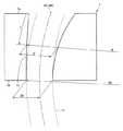
図1は、従来の丸ビレット鋳片の連続鋳造用鋳型の構成を模式的に示す垂直断面図である。同図に示すように、湾曲型連続鋳造機に用いられる従来の鋳型101は、その内周面における湾曲外側に沿う面101cの湾曲半径R0が一定である。この湾曲半径R0は、鋳型101から引き出される鋳片11の湾曲外側の湾曲半径と概ね一致する。鋳型下端101bでの内径D0は、鋳造する鋳片11の直径毎に定められる。FIG. 1 is a vertical sectional view schematically showing the configuration of a conventional casting mold for round billet cast slabs. As shown in the figure, the
鋳型101の内周面は、前記特許文献1〜3に提案された鋳型のように、鋳型101の内径を上端101aから下端101bに向かうに従って縮小させる、すなわち下端101bから上端101aに向かうに従って拡大させるテーパーが施される。このとき、鋳型101の内周面は、湾曲外側が一定の湾曲半径R0で制限されているため、内径の拡大した分が湾曲内側に広がる。これにより、鋳型101の内径の中心点を下端101bから上端101aまで結んでなる中心線MCは、丸ビレット鋳片11の中心線BCに対し、鋳型下端101bでは一致しているものの、鋳型101の上端101aへ向かうほど湾曲内側に大きく外れた状態になる。The inner peripheral surface of the
このような鋳型101を用いて丸ビレット鋳片11を連続鋳造する際、鋳片11は常に湾曲内側から湾曲外側に向けて偏った力を受ける。そのため、従来の鋳型101では、鋳片11と鋳型101の内周面との接触は全周で均一にはならず、鋳片11が変形する問題が起こる。この問題は、例えば、凝固収縮量が異なる鋼を鋳造対象とする場合や、鋳造中に鋳造速度が変化する場合に、鋳片が受ける偏った力が変化することから、起こりやすい。 When the
このような問題を解決するため、本発明の連続鋳造用鋳型は、鋳型内径の変化率を規定することに加え、鋳型の湾曲半径の変化率、およびそれらの変化率間の関係を規定したものである。 In order to solve such problems, the continuous casting mold of the present invention defines not only the rate of change of the mold inner diameter but also the rate of change of the bending radius of the mold and the relationship between these rates of change. It is.
すなわち、本発明の鋳型は、湾曲型連続鋳造機を用いて丸ビレット鋳片を連続鋳造するための鋳型であって、鋳型下端での内径をD0[m]とし、鋳型下端での湾曲外側の湾曲半径をR0[m]とし、鋳造方向に沿った単位長さ当たりの鋳型内径の変化率Tp[%/m]を下記(1)式で表し、鋳造方向に沿った単位長さ当たりの湾曲外側の湾曲半径の変化率Rp[%/m]を下記(2)式で表した場合に、鋳型内径変化率Tpと湾曲半径変化率Rpとは下記(3)式の関係を満足するものである。
Tp=(1/D0)×(dD/dx)×100[%/m] ・・・(1)式
但し、前記(1)式中のDは鋳型冷却面上端からxの距離における鋳型内径を示す。
Rp=(1/R0)×(dR/dx)×100[%/m] ・・・(2)式
但し、前記(2)式中のRは鋳型冷却面上端からxの距離における湾曲外側の湾曲半径を示す。
Rp=(Tp/2)×(D0/R0) ・・・(3)式
図2は、本発明の丸ビレット鋳片の連続鋳造用鋳型の構成を模式的に示す垂直断面図である。同図に示すように、湾曲型連続鋳造機に用いられる本発明の鋳型1は、鋳型1の下端1bでの内径をD0とし、鋳型下端1bでの内周面における湾曲外側に沿う面1cの湾曲半径をR0とする。その鋳型下端1bでの内径D0は、鋳造する鋳片11の直径毎に定められる。その鋳型下端1bでの湾曲半径R0は、鋳型1から引き出される鋳片11の湾曲外側の湾曲半径と概ね一致し、湾曲型連続鋳造機に固有のものである。That is, the mold of the present invention is a mold for continuously casting round billet cast pieces using a curved continuous casting machine, wherein the inner diameter at the lower end of the mold is D0 [m], and the outer curved side at the lower end of the mold. R0 [m] is the curvature radius of the mold, and the rate of change Tp [% / m] of the mold inner diameter per unit length along the casting direction is expressed by the following equation (1), and per unit length along the casting direction: When the change rate Rp [% / m] of the bend radius outside the bend is expressed by the following equation (2), the mold inner diameter change rate Tp and the bend radius change rate Rp satisfy the relationship of the following equation (3). Is.
Tp = (1 / D0 ) × (dD / dx) × 100 [% / m] (1) where D is the inner diameter of the mold at a distance x from the upper end of the mold cooling surface. Indicates.
Rp = (1 / R0 ) × (dR / dx) × 100 [% / m] (2) where R in the equation (2) is outside the curve at a distance x from the upper end of the mold cooling surface. Indicates the radius of curvature.
Rp = (Tp / 2) × (D0 / R0 ) (3) Formula FIG. 2 is a vertical sectional view schematically showing a configuration of a continuous casting mold of the round billet cast piece of the present invention. . As shown in the figure, the mold 1 of the present invention used in the curved type continuous casting machine, the inner diameter at the
鋳型1の内周面は、その内径を下端1bから上端1aに向かうに従って次第に拡大させるテーパーが施される。このとき、鋳型冷却面上端1aからxの距離において、鋳型内径をDとしたとき、この位置での鋳型内径変化率Tpは、上記(1)式で表すことができる。同じく、鋳型冷却面上端1aからxの距離において、湾曲外側に沿う面1cの湾曲半径をRとしたとき、この位置での湾曲外側の湾曲半径変化率Rpは、上記(2)式で表すことができる。そして、鋳型冷却面上端1aからxの距離の位置では、その位置での鋳型内径変化率Tpと湾曲半径変化率Rpとが上記(3)式の関係を満足するように、鋳型内径Dおよび湾曲半径Rが設定される。 The inner peripheral surface of the mold 1 is tapered so that its inner diameter gradually increases from the
このような上記(3)式の規定に従って鋳型内径Dおよび湾曲半径Rを設定すると、鋳型1の内周面は、その内径が下端1bから上端1aに向かうに従って次第に拡大するわけであるが、内径の拡大した分が湾曲外側と湾曲内側とに均等に振り分けられて広がる。すなわち、鋳型1の内径の中心点を下端1bから上端1aまで結んでなる中心線MCは、丸ビレット鋳片11の中心線BCに対し、鋳型下端1bから鋳型上端1aまでの全域にわたって合致した状態になる。 When the mold inner diameter D and the bending radius R are set in accordance with the above-mentioned formula (3), the inner peripheral surface of the mold 1 gradually increases as the inner diameter increases from the
このような状態を上記(3)式で規定する理由は、以下のとおりである。鋳型内周面の中心線MCと、鋳片11の中心線BCとを合致させるには、鋳片11の中心線BCを中心に、鋳型1の内径の拡大した分を湾曲外側と湾曲内側に均等に振り分けることが必要である。そのためには、鋳型冷却面上端1aからxの距離の位置での湾曲外側の湾曲半径Rに、その位置での鋳型内径変化率Tpの半分(1/2)を寄与させればよい。そうすると、湾曲外側の湾曲半径Rは、鋳型内径変化率Tpに基づいて、下記(4)式で表すことができる。
R=R0+D0×(Tp/2) ・・・(4)式
同様に湾曲外側の湾曲半径Rは、湾曲半径変化率Rpに基づいて、下記(5)式で表すことができる。
R=R0+R0×Rp ・・・(5)式
上記(4)式および上記(5)式より、上記(3)式を導くことができる。よって、上記(3)式の関係を満足すれば、鋳型内周面の中心線MCと、鋳片11の中心線BCとが合致することになる。The reason why such a state is defined by the above equation (3) is as follows. In order to match the center line MC of the inner peripheral surface of the mold with the center line BC of the
R = R0 + D0 × (Tp / 2) (4) Similarly, the bending radius R outside the bending can be expressed by the following expression (5) based on the bending radius change rate Rp.
R = R0 + R0 × Rp (5) Formula From the above formula (4) and the above formula (5), the above formula (3) can be derived. Therefore, if the relationship of the above expression (3) is satisfied, the center line MC of the inner peripheral surface of the mold and the center line BC of the
このような本発明の連続鋳造用鋳型によれば、この鋳型を用いて丸ビレット鋳片を連続鋳造する際、鋳型内周面の中心線と、鋳片の中心線とが合致していることから、鋳片は鋳型から偏った力を受けることはなく、全周に均等な力を受ける。そのため、鋳片と鋳型内周面との接触が全周にわたって均一で良好になり、その結果、安定して高品質な丸ビレット鋳片を得ることができる。これは、凝固収縮量が異なる鋼を鋳造対象とする場合や、鋳造中に鋳造速度が変化する場合であっても変わらない。 According to such a continuous casting mold of the present invention, when a round billet slab is continuously cast using this mold, the center line of the inner peripheral surface of the mold and the center line of the slab are matched. Therefore, the slab does not receive a biased force from the mold and receives a uniform force on the entire circumference. Therefore, the contact between the slab and the inner peripheral surface of the mold is uniform and good over the entire circumference, and as a result, a high-quality round billet slab can be obtained stably. This does not change even when steels with different solidification shrinkage are to be cast or when the casting speed changes during casting.
続いて、本発明の連続鋳造用鋳型の好適な具体例を説明する。 Then, the suitable specific example of the casting mold for continuous casting of this invention is demonstrated.
具体例として、鋳造方向に沿って3つの領域に区分されており、鋳型内径変化率Tpは、溶鋼が注入される側の鋳型冷却面上端から50〜100[mm]の間の領域は12〜16[%/m]で、この領域に連続して鋳型冷却面上端より250〜300[mm]の間の領域は12〜16[%/m]から0.8〜1.4[%/m]まで連続的に変化させ、さらにこの領域に連続して鋳型下端までの間の領域は0.8〜1.4[%/m]とすることができる。このとき、湾曲半径変化率Rpは、その鋳型内径変化率Tpに基づいて、上記(3)式の関係を満足するように定める。 As a specific example, it is divided into three regions along the casting direction, and the mold inner diameter change rate Tp is 12 to 12 in the region between 50 and 100 [mm] from the upper end of the mold cooling surface where molten steel is injected. 16 [% / m], and the region between 250 and 300 [mm] from the upper end of the mold cooling surface is continuously 12 to 16 [% / m] to 0.8 to 1.4 [% / m]. ], And the region between this region and the lower end of the mold can be 0.8 to 1.4 [% / m]. At this time, the bending radius change rate Rp is determined based on the mold inner diameter change rate Tp so as to satisfy the relationship of the above expression (3).
言い換えると、湾曲半径変化率Rpは、溶鋼が注入される側の鋳型冷却面上端から50〜100[mm]の間の領域は6×(D0/R0)〜8×(D0/R0)[%/m]で、この領域に連続して鋳型冷却面上端より250〜300[mm]の間の領域は6×(D0/R0)〜8×(D0/R0)[%/m]から0.4×(D0/R0)〜0.7×(D0/R0)[%/m]まで連続的に変化させ、さらにこの領域に連続して鋳型下端までの間の領域は0.4×(D0/R0)〜0.7×(D0/R0)[%/m]とすることもできる。このとき、鋳型内径変化率Tpは、その湾曲半径変化率Rpに基づいて、上記(3)式の関係を満足するように定める。In other words, the curvature radius change rate Rp is 6 × (D0 / R0 ) to 8 × (D0 / R) in the region between 50 and 100 [mm] from the upper end of the mold cooling surface on the molten steel injection side.0 ) [% / m], and the region between 250 and 300 [mm] from the upper end of the mold cooling surface is continuously 6 × (D0 / R0 ) to 8 × (D0 / R0 ). [% / M] is continuously changed from 0.4 × (D0 / R0 ) to 0.7 × (D0 / R0 ) [% / m], and the lower end of the mold continuously in this region. The region up to can also be 0.4 × (D0 / R0 ) to 0.7 × (D0 / R0 ) [% / m]. At this time, the mold inner diameter change rate Tp is determined based on the curvature radius change rate Rp so as to satisfy the relationship of the above expression (3).
図3は、本発明の丸ビレット鋳片の連続鋳造用鋳型の具体例を説明するための垂直断面図である。同図は、便宜的に、鋳型の内周面のテーパーを一定にしており、湾曲状態を示していない。 FIG. 3 is a vertical sectional view for explaining a specific example of a continuous casting mold for round billet cast pieces according to the present invention. In the figure, for convenience, the taper of the inner peripheral surface of the mold is constant, and the curved state is not shown.
図3に示すように、本発明の鋳型1は、溶鋼10が注入される側の鋳型1の冷却面上端1aから下端1bまでを、鋳造方向に沿って3つの領域A1、A2、A3に区分される。第1領域A1と第2領域A2との境界は、鋳型1の冷却面上端1aより50〜100[mm]の区間内にあり、第2領域A2と第3領域A3との境界は、鋳型1の冷却面上端1aから250〜300[mm]の区間内にある。鋳型内径変化率Tpは、第1領域A1内で12〜16[%/m]に、これに連続する第2領域A2内で12〜16[%/m]から0.8〜1.4[%/m]まで連続的に変化し、さらにこれに連続する第3領域A3内で0.8〜1.4[%/m]となるように構成する。連続鋳造時には、鋳型1内の溶鋼10の表面にモールドパウダー12が供給される。 As shown in FIG. 3, the mold 1 of the present invention is divided into three regions A1, A2, and A3 along the casting direction from the cooling surface
鋳型冷却面上端から50〜100[mm]の間の第1領域で鋳型内径変化率Tpを12〜16[%/m]に設定するのは、その区間が鋳型内周面と鋳片との間の接触を均一にするために有効だからである。すなわち、その区間が50[mm]未満であると、凝固シェルの収縮よりも鋳型の収縮が小さくなって接触が不均一になり、縦割れが発生するからである。一方、その区間が100[mm]を超えると、鋳型の収縮が大きくなりすぎて鋳型と鋳片との焼き付きによる拘束が発生するからである。鋳型内径変化率Tpは、規定値より大きすぎると拘束が発生し、小さすぎると縦割れが発生する。 The mold inner diameter change rate Tp is set to 12 to 16 [% / m] in the first region between 50 and 100 [mm] from the upper end of the mold cooling surface because the section is between the mold inner peripheral surface and the slab. This is because it is effective to make the contact between them uniform. That is, if the section is less than 50 [mm], the shrinkage of the mold becomes smaller than the shrinkage of the solidified shell, the contact becomes uneven, and vertical cracks occur. On the other hand, if the section exceeds 100 [mm], the shrinkage of the mold becomes too large, and the restraint due to the seizure between the mold and the cast piece occurs. When the mold inner diameter change rate Tp is too larger than a specified value, restraint occurs, and when it is too small, vertical cracks occur.
また、その第1領域に連続して鋳型冷却面上端より250〜300[mm]の間の第2領域で鋳型内径変化率Tpを12〜16[%/m]から0.8〜1.4[%/m]まで連続的に変化させるのは、その区間が250[mm]未満であると、凝固シェルの収縮よりも鋳型の収縮が小さくなって接触が不均一になり、縦割れが発生するからである。一方、その区間が300[mm]を超えると、鋳型の収縮が大きくなりすぎて鋳型と鋳片との焼き付きによる拘束が発生するからである。鋳型内径変化率Tpは、規定値より大きすぎると拘束が発生し、小さすぎると縦割れが発生する。さらに、その第2領域に連続して鋳型下端までの間の第3領域で鋳型内径変化率Tpを0.8〜1.4[%/m]としているのも、同様の理由からである。 Further, the mold inner diameter change rate Tp is changed from 12 to 16 [% / m] to 0.8 to 1.4 in a second area between 250 and 300 [mm] from the upper end of the mold cooling surface continuously to the first area. If the section is continuously changed to less than 250 [mm], the mold shrinkage is smaller than the shrinkage of the solidified shell, resulting in non-uniform contact and vertical cracking. Because it does. On the other hand, when the section exceeds 300 [mm], the shrinkage of the mold becomes too large, and the restraint due to the seizure between the mold and the cast piece occurs. When the mold inner diameter change rate Tp is too larger than a specified value, restraint occurs, and when it is too small, vertical cracks occur. Furthermore, the reason why the mold inner diameter change rate Tp is set to 0.8 to 1.4 [% / m] in the third area continuously from the second area to the lower end of the mold is also the same reason.
本具体例の連続鋳造用鋳型を使用すれば、鋳片と鋳型内周面との接触がより一層良好になって高品質な丸ビレット鋳片を得ることができる。さらに、鋳型内周面と鋳片との間の伝熱媒体となるモールドパウダーについては、以下の物性および成分を有するものを本発明の鋳型に使用することで、従来のモールドパウダーを使用するよりもさらに高品質な丸ビレット鋳片を得ることができる。 If the continuous casting mold of this specific example is used, the contact between the slab and the inner peripheral surface of the mold is further improved, and a high-quality round billet slab can be obtained. Furthermore, with respect to the mold powder serving as a heat transfer medium between the inner peripheral surface of the mold and the slab, by using the mold powder having the following physical properties and components for the mold of the present invention, it is possible to use the conventional mold powder. Furthermore, it is possible to obtain a round billet slab of higher quality.
本発明の丸ビレット鋳片の連続鋳造用鋳型には、1573[K]における粘度が0.1〜1.0[Pa・s]、凝固点が1273[K]以上であり、((CaO+CaF2×0.718)/SiO2)で表される質量濃度比が1.0〜1.4で、Na2Oに換算したNa量が5.0[mass%]以下、F濃度が7.0[mass%]以下、MgOに換算したMg量が5〜13[mass%]、Al2O3に換算したAl量が6〜18[mass%]であるモールドパウダーを用いることができる。表1に、モールドパウダーの物性および成分を示す。The mold for continuous casting of the round billet slab of the present invention has a viscosity at 1573 [K] of 0.1 to 1.0 [Pa · s] and a freezing point of 1273 [K] or more, ((CaO + CaF2 × The mass concentration ratio represented by 0.718) / SiO2 ) is 1.0 to 1.4, the Na amount converted to Na2 O is 5.0 [mass%] or less, and the F concentration is 7.0 [ mass%] or less, the amount of Mg in terms of MgO is 5~13 [mass%], Al amount calculated as Al2 O3 can be used mold powder is 6~18 [mass%]. Table 1 shows the physical properties and components of the mold powder.

このモールドパウダーに関し、1573[K]における粘度が0.1[Pa・s]未満であると、鋳型内周面と鋳片との間へのパウダーの流入が不均一となって抜熱が不均一になり、縦割れが発生したり、拘束が発生したり、溶鋼中にパウダーが巻き込まれて欠陥が発生する。一方、その粘度が1.0[Pa・s]を超えると、鋳型内周面と鋳片との間へのパウダーの流入が不足して拘束が発生する。 With respect to this mold powder, if the viscosity at 1573 [K] is less than 0.1 [Pa · s], the powder does not flow uniformly between the inner peripheral surface of the mold and the cast slab, and heat is not removed. It becomes uniform, vertical cracks occur, restraints occur, and powder is entrained in the molten steel, resulting in defects. On the other hand, when the viscosity exceeds 1.0 [Pa · s], the inflow of the powder between the inner peripheral surface of the mold and the cast piece is insufficient and restraint occurs.
凝固点が1273[K]未満であると、鋳型内周面と鋳片との間において、パウダーの液相が多くなって冷却が強くなりすぎるので、熱応力により鋳片が変形し、縦割れが発生する。 If the freezing point is less than 1273 [K], the liquid phase of the powder increases between the inner peripheral surface of the mold and the slab, and the cooling becomes too strong. appear.
((CaO+CaF2×0.718)/SiO2)で表される質量濃度比が1.0未満であると、溶鋼中のMnをパウダー中のSiO2が酸化して組成が変化し、鋳片の表面に欠陥が生じる。また、MgOに換算したMg量が5[mass%]未満であると、結晶化が安定しないので、冷却が強くなり、縦割れが発生する。一方、((CaO+CaF2×0.718)/SiO2)で表される質量濃度比が1.4を超えたり、MgOに換算したMg量が13[mass%]を超えると、パウダーフィルムの収縮が大きくなりすぎて鋳片と鋳型内周面との間の接触が悪化して縦割れが発生し、または、凝固点が高くなりすぎてパウダーが溶融しない。When the mass concentration ratio represented by ((CaO + CaF2 × 0.718) / SiO2 ) is less than 1.0, Mn in the molten steel is oxidized by SiO2 in the powder to change the composition, and the slab Defects are generated on the surface. On the other hand, if the amount of Mg converted to MgO is less than 5 [mass%], crystallization is not stable, so that cooling becomes strong and vertical cracks occur. On the other hand, if the mass concentration ratio represented by ((CaO + CaF2 × 0.718) / SiO2 ) exceeds 1.4 or the Mg amount converted to MgO exceeds 13 [mass%], the shrinkage of the powder film Becomes too large and the contact between the slab and the inner peripheral surface of the mold deteriorates, causing vertical cracks, or the freezing point becomes too high and the powder does not melt.
Na2Oに換算したNa量が5.0[mass%]を超えたり、F濃度が7.0[mass%]を超えると、粉末の溶融特性が不良となってノロ咬みなどの欠陥が発生する。If the amount of Na converted to Na2 O exceeds 5.0 [mass%] or the F concentration exceeds 7.0 [mass%], the melting characteristics of the powder become poor, and defects such as bite bites occur. To do.
Al2O3に換算したAl量が6[mass%]未満であると、結晶の組成が鋳込み中に変化して冷却が不均一になる。一方、そのAl量が18[mass%]を超えると、凝固点が高くなりすぎて、溶融したパウダーが流入しにくくなる。When the amount of Al converted to Al2 O3 is less than 6 [mass%], the composition of crystals changes during casting and cooling becomes uneven. On the other hand, when the Al content exceeds 18 [mass%], the freezing point becomes too high, and the melted powder is difficult to flow in.
したがって、ここで規定した物性および成分を有するモールドパウダーを本発明の鋳型内溶鋼の表面に供給しつつ連続鋳造すれば、さらに良好な品質の丸ビレット鋳片を製造できる。 Therefore, if continuous casting is performed while supplying mold powder having the physical properties and components defined here to the surface of the molten steel in the mold of the present invention, a round billet slab of even better quality can be produced.
本発明の鋳型およびその鋳型を用いた連続鋳造方法による効果を確認するために、湾曲半径(R0)が10[m]で一点矯正式の湾曲型連続鋳造機を用いて試験を行った。本実施例での試験には、C:0.06〜0.35[mass%]、およびMn:0.8〜1.8[mass%]を含有する鋼を用いた。Crは含有しなくてもよいが、含有する場合は3[mass%]以下とした。特に、表2に示す3ランクの鋼種A、B、Cで鋳造試験を行った。In order to confirm the effect of the casting mold of the present invention and the continuous casting method using the casting mold, a test was conducted using a bending type continuous casting machine having a curvature radius (R0 ) of 10 [m] and a one-point correction type. In the test in this example, steel containing C: 0.06 to 0.35 [mass%] and Mn: 0.8 to 1.8 [mass%] was used. Cr may not be contained, but when it is contained, the content is set to 3 [mass%] or less. In particular, a casting test was performed on three ranks of steel types A, B, and C shown in Table 2.
本実施例では、表3に示す鋳型M1〜M20(冷却面下端内径(D0)は225[mm]、長さは900[mm])に給湯し、この溶鋼の表面に、表4に示すモールドパウダーP1〜P11を供給し、鋳造速度が2.0[m/分]で連続鋳造した。表5に、本実施例での鋼種A〜C、鋳型M1〜M20、およびパウダーP1〜P11の組合せを表す鋳造条件A〜AFを示す。In this example, hot water was supplied to the molds M1 to M20 shown in Table 3 (the cooling surface lower end inner diameter (D0 ) was 225 [mm] and the length was 900 [mm]), and the surface of this molten steel is shown in Table 4. Mold powders P1 to P11 were supplied, and continuous casting was performed at a casting speed of 2.0 [m / min]. Table 5 shows casting conditions A to AF representing combinations of steel types A to C, molds M1 to M20, and powders P1 to P11 in this example.
試験結果の評価は、鋳型内周面と鋳片との接触状況を表す鋳型銅板温度の変動幅、縦割れ発生率、および引き抜き不能事故の有無で行った。 The evaluation of the test results was performed based on the fluctuation range of the mold copper plate temperature representing the contact state between the inner peripheral surface of the mold and the slab, the occurrence rate of vertical cracks, and the presence or absence of an undrawn accident.
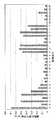
図4は、実施例での鋳造条件毎の鋳型銅板温度の変動幅を示す図である。同図の鋳型温度変動幅は、鋳型冷却面上端から150[mm]の位置に設置した熱電対の温度変動幅を実効値(積分平均)で示したものである。その熱電対は銅板表面から15mm内側に設置した。 FIG. 4 is a diagram showing the fluctuation range of the mold copper plate temperature for each casting condition in the example. The mold temperature fluctuation range of the figure shows the temperature fluctuation range of the thermocouple installed at a position of 150 mm from the upper end of the mold cooling surface as an effective value (integral average). The thermocouple was installed 15 mm inside from the copper plate surface.
図5は、実施例での鋳造条件毎の縦割れ発生指数を示す図である。同図の縦割れ発生指数は、鋳片の単位長さ当たりの割れ長さである。 FIG. 5 is a diagram showing a longitudinal crack occurrence index for each casting condition in the example. The longitudinal crack occurrence index in the figure is the crack length per unit length of the slab.
図4および図5より明らかなように、本発明例である鋳造条件I〜Q、U、V、およびAA〜AFについては、鋳型銅板温度の変動幅はまったく問題のない範囲であり、縦割れの発生もほとんどなかった。しかも、ブレークアウトや拘束ブレークアウト警報も発せられなかった。 As is clear from FIGS. 4 and 5, for the casting conditions I to Q, U, V, and AA to AF, which are examples of the present invention, the fluctuation range of the mold copper plate temperature is in the range where there is no problem at all, and the vertical cracks. There was almost no outbreak. Moreover, no breakout or restraint breakout warning was issued.
これに対して、比較例である鋳造条件A、C、E、F、R〜T、W〜Zでは、鋳型銅板温度の変動幅が大きく実操業において問題となり、縦割れも大きかった。この中で、特に鋳造条件W、X、Y、Zについては、比較例であるパウダーP4、P5、P6、P7が採用されており、モールドパウダーの不適正により、銅板温度の大きな変動が起こった。鋳造条件R、S、Tについては、比較例である鋳型M18、M19、M20が採用されており、鋳型内径変化率は適正であったが、湾曲半径変化率が不適正であったため、鋳片と鋳型内周面との接触が均一に保たれなかった。 On the other hand, in the casting conditions A, C, E, F, R to T, and W to Z, which are comparative examples, the fluctuation range of the mold copper plate temperature was large, causing a problem in actual operation, and the vertical crack was also large. Among these, powders P4, P5, P6, and P7, which are comparative examples, are employed particularly for casting conditions W, X, Y, and Z, and a large variation in the copper plate temperature occurred due to improper mold powder. . For casting conditions R, S, and T, comparative molds M18, M19, and M20 were adopted, and the mold inner diameter change rate was appropriate, but the bending radius change rate was inappropriate. And contact with the inner peripheral surface of the mold could not be kept uniform.
また、比較例である鋳造条件B、D、G、Hでは、銅板温度の変動は小さいものの、比較例である鋳型M1、M4、M7、M8が採用されており、鋳型内径変化率が不適であったため、引き抜き不能の事故が発生した。 Further, in the casting conditions B, D, G, and H which are comparative examples, although the fluctuation of the copper plate temperature is small, the comparative molds M1, M4, M7 and M8 are adopted and the mold inner diameter change rate is inappropriate. As a result, an accident that could not be pulled out occurred.
本発明の丸ビレット鋳片の連続鋳造用鋳型、およびその鋳型を用いた連続鋳造方法によれば、湾曲型連続鋳造機を用いて丸ビレット鋳片を連続鋳造する際、鋳片は全周に均等な力を受けて、鋳片と鋳型内周面との接触が全周にわたって均一で良好になるため、鋳造欠陥の無い高品質な丸ビレット鋳片を安定して製造することができる。したがって、本発明は、湾曲型連続鋳造機を用いて高品質な丸ビレット鋳片を製造することが可能な連続鋳造用鋳型および連続鋳造方法として、極めて有用である。 According to the continuous casting mold of the round billet cast of the present invention and the continuous casting method using the mold, when the round billet cast is continuously cast using a curved continuous casting machine, the cast is placed on the entire circumference. Under uniform force, contact between the slab and the inner peripheral surface of the mold is uniform and good over the entire circumference, so that a high-quality round billet slab free from casting defects can be stably produced. Therefore, the present invention is extremely useful as a continuous casting mold and a continuous casting method capable of producing a high-quality round billet slab using a curved continuous casting machine.
1 鋳型
1a 鋳型上端
1b 鋳型下端
1c 鋳型内周面における湾曲外側に沿う面
10 溶鋼
11 丸ビレット鋳片
12 モールドパウダーDESCRIPTION OF SYMBOLS 1
Claims (4)
Translated fromJapanese鋳造方向に沿った単位長さ当たりの鋳型内径の変化率Tp[%/m]を下記(1)式で表し、
鋳造方向に沿った単位長さ当たりの湾曲外側の湾曲半径の変化率Rp[%/m]を下記(2)式で表した場合に、
鋳型内径変化率Tpと湾曲半径変化率Rpとは下記(3)式の関係を満足することを特徴とする丸ビレット鋳片の連続鋳造用鋳型。
Tp=(1/D0)×(dD/dx)×100[%/m] ・・・(1)式
但し、前記(1)式中のDは鋳型冷却面上端からxの距離における鋳型内径を示す。
Rp=(1/R0)×(dR/dx)×100[%/m] ・・・(2)式
但し、前記(2)式中のRは鋳型冷却面上端からxの距離における湾曲外側の湾曲半径を示す。
Rp=(Tp/2)×(D0/R0) ・・・(3)式A mold for continuously casting round billet slabs using a curved continuous casting machine having an inner diameter D0 [m] at the lower end of the mold and a curved outer radius R0 [m] at the lower end of the mold. Because
The rate of change Tp [% / m] of the mold inner diameter per unit length along the casting direction is expressed by the following equation (1):
When the rate of change Rp [% / m] of the bending radius outside the bending per unit length along the casting direction is expressed by the following equation (2):
The mold for continuous casting of round billet cast slabs characterized in that the mold inner diameter change rate Tp and the bending radius change rate Rp satisfy the relationship of the following formula (3).
Tp = (1 / D0 ) × (dD / dx) × 100 [% / m] (1) where D is the inner diameter of the mold at a distance x from the upper end of the mold cooling surface. Indicates.
Rp = (1 / R0 ) × (dR / dx) × 100 [% / m] (2) where R is the outside of the curve at a distance x from the upper end of the mold cooling surface. Indicates the radius of curvature.
Rp = (Tp / 2) × (D0 / R0 ) (3)
前記連続鋳造用鋳型内に注入した溶鋼の表面に、1573[K]における粘度が0.1〜1.0[Pa・s]、凝固点が1273[K]以上であり、((CaO+CaF2×0.718)/SiO2)で表される質量濃度比が1.0〜1.4で、Na2Oに換算したNa量が5.0[mass%]以下、F濃度が7.0[mass%]以下、MgOに換算したMg量が5〜13[mass%]、Al2O3に換算したAl量が6〜18[mass%]であるモールドパウダーを供給しつつ、連続鋳造することを特徴とする丸ビレット鋳片の連続鋳造方法。A continuous casting method using the continuous casting mold of the round billet cast piece according to any one of claims 1 to 3,
On the surface of the molten steel poured into the continuous casting mold, the viscosity at 1573 [K] is 0.1 to 1.0 [Pa · s] and the freezing point is 1273 [K] or more ((CaO + CaF2 × 0 718) / SiO2 ), the mass concentration ratio is 1.0 to 1.4, the Na amount converted to Na2 O is 5.0 [mass%] or less, and the F concentration is 7.0 [mass. %] or less, the amount of Mg in terms of MgO is 5 to 13 [mass%], while supplying mold powder Al content in terms of Al2 O3 is having 6 to 18 [mass%], the continuous casting A continuous casting method of a round billet cast.
Priority Applications (11)
| Application Number | Priority Date | Filing Date | Title |
|---|---|---|---|
| JP2007170396AJP5018274B2 (en) | 2007-06-28 | 2007-06-28 | Mold for continuous casting of round billet slab and continuous casting method |
| BRPI0721797ABRPI0721797B1 (en) | 2007-06-28 | 2007-07-25 | mold to continuously cast a round billet and continuous round billet casting process. |
| CA2683984ACA2683984C (en) | 2007-06-28 | 2007-07-25 | Continuous casting mold and continuous casting method of round billet |
| RU2010102712/02ARU2434707C2 (en) | 2007-06-28 | 2007-07-25 | Crystalliser for continuous casting and method of continuous casting of round billet |
| PCT/JP2007/064564WO2009001481A1 (en) | 2007-06-28 | 2007-07-25 | Mold for continuous casting of round billet cast piece and method of continuous casting thereof |
| CN2007800530491ACN101678442B (en) | 2007-06-28 | 2007-07-25 | Mold for continuous casting of round billet castings and continuous casting method |
| EP07791280.6AEP2158984A4 (en) | 2007-06-28 | 2007-07-25 | Mold for continuous casting of round billet cast piece and method of continuous casting thereof |
| MX2009012872AMX2009012872A (en) | 2007-06-28 | 2007-07-25 | Mold for continuous casting of round billet cast piece and method of continuous casting thereof. |
| ARP070105181AAR063893A1 (en) | 2007-06-28 | 2007-11-21 | CONTINUOUS COLADA MOLD AND ROUND TOCH CONTINUOUS COLADA METHOD |
| US12/579,495US8225843B2 (en) | 2007-06-28 | 2009-10-15 | Continuous casting mold and continuous casting method of round billet |
| US13/529,262US8397792B2 (en) | 2007-06-28 | 2012-06-21 | Continuous casting mold and continuous casting method of round billet |
Applications Claiming Priority (1)
| Application Number | Priority Date | Filing Date | Title |
|---|---|---|---|
| JP2007170396AJP5018274B2 (en) | 2007-06-28 | 2007-06-28 | Mold for continuous casting of round billet slab and continuous casting method |
Publications (2)
| Publication Number | Publication Date |
|---|---|
| JP2009006364A JP2009006364A (en) | 2009-01-15 |
| JP5018274B2true JP5018274B2 (en) | 2012-09-05 |
Family
ID=40185311
Family Applications (1)
| Application Number | Title | Priority Date | Filing Date |
|---|---|---|---|
| JP2007170396AActiveJP5018274B2 (en) | 2007-06-28 | 2007-06-28 | Mold for continuous casting of round billet slab and continuous casting method |
Country Status (10)
| Country | Link |
|---|---|
| US (2) | US8225843B2 (en) |
| EP (1) | EP2158984A4 (en) |
| JP (1) | JP5018274B2 (en) |
| CN (1) | CN101678442B (en) |
| AR (1) | AR063893A1 (en) |
| BR (1) | BRPI0721797B1 (en) |
| CA (1) | CA2683984C (en) |
| MX (1) | MX2009012872A (en) |
| RU (1) | RU2434707C2 (en) |
| WO (1) | WO2009001481A1 (en) |
Families Citing this family (6)
| Publication number | Priority date | Publication date | Assignee | Title |
|---|---|---|---|---|
| CN101844210B (en)* | 2010-04-27 | 2012-08-08 | 攀钢集团工程技术有限公司 | Continuous casting machine arc section supporting structure and mounting method thereof |
| JP5817681B2 (en)* | 2012-08-22 | 2015-11-18 | 新日鐵住金株式会社 | Mold for continuous casting of high alloy steel round billet slab and continuous casting method |
| JP6136782B2 (en)* | 2013-09-04 | 2017-05-31 | 新日鐵住金株式会社 | High Cr steel continuous casting method |
| KR102073318B1 (en)* | 2015-11-05 | 2020-02-03 | 닛폰세이테츠 가부시키가이샤 | Mold flux for continuous casting and continuous casting method |
| US10788934B2 (en)* | 2017-05-14 | 2020-09-29 | Microsoft Technology Licensing, Llc | Input adjustment |
| CN115446279A (en)* | 2022-09-06 | 2022-12-09 | 中南大学 | Corner temperature field thermal simulation device of round chamfer crystallizer and application |
Family Cites Families (15)
| Publication number | Priority date | Publication date | Assignee | Title |
|---|---|---|---|---|
| DE2923398C2 (en)* | 1979-06-06 | 1981-07-09 | Mannesmann AG, 4000 Düsseldorf | Device for measuring a curved continuous casting mold |
| CA1209770A (en) | 1982-12-17 | 1986-08-19 | Robert C. Heritage | Openwork screen assembly |
| JPS59165748A (en) | 1984-02-24 | 1984-09-19 | アイカ工業株式会社 | Top plate |
| JPS6432184A (en) | 1987-07-28 | 1989-02-02 | Yokogawa Electric Corp | Continuous core loss measuring instrument |
| JPH0628093B2 (en) | 1989-06-20 | 1994-04-13 | 科学技術庁金属材料技術研究所長 | Magnetic recording medium |
| RU2015175C1 (en)* | 1991-03-05 | 1994-06-30 | Виниченко Николай Иванович | Method of producing slag-forming mixture |
| RU2044597C1 (en)* | 1992-12-24 | 1995-09-27 | Владимир Ильич Лебедев | Crystallizer of curvilinear-type machine for continuous casting of metal |
| IT1265065B1 (en)* | 1993-05-17 | 1996-10-30 | Giovanni Arvedi | PERFECTED INGOT MILL FOR CONTINUOUS STEEL CASTING, PARTICULARLY SUITABLE FOR CONTINUOUS CASTING OF THIN Slabs |
| JP3008821B2 (en)* | 1994-07-29 | 2000-02-14 | 住友金属工業株式会社 | Continuous casting method and apparatus for thin slab |
| JP3022211B2 (en) | 1994-11-08 | 2000-03-15 | 住友金属工業株式会社 | Mold for continuous casting of round billet slab and continuous casting method using the mold |
| DE19742795A1 (en)* | 1997-09-27 | 1999-04-01 | Schloemann Siemag Ag | Funnel geometry of a mold for the continuous casting of metal |
| CN2386908Y (en)* | 1999-09-21 | 2000-07-12 | 许壮凌 | Crystallizer |
| CZ290001B6 (en)* | 2000-04-28 | 2002-05-15 | Třinecké Železárny A. S. | Circular crystallizer |
| JP3886774B2 (en)* | 2001-10-30 | 2007-02-28 | 三島光産株式会社 | Continuous casting mold considering slab casting radius change due to shrinkage and continuous casting equipment using the same |
| CN1528545A (en)* | 2003-09-26 | 2004-09-15 | 燕山大学 | Continuous caster roll profile with continuous bending section and two continuous straightening sections |
- 2007
- 2007-06-28JPJP2007170396Apatent/JP5018274B2/enactiveActive
- 2007-07-25BRBRPI0721797Apatent/BRPI0721797B1/enactiveIP Right Grant
- 2007-07-25WOPCT/JP2007/064564patent/WO2009001481A1/enactiveApplication Filing
- 2007-07-25CNCN2007800530491Apatent/CN101678442B/enactiveActive
- 2007-07-25CACA2683984Apatent/CA2683984C/ennot_activeExpired - Fee Related
- 2007-07-25EPEP07791280.6Apatent/EP2158984A4/ennot_activeWithdrawn
- 2007-07-25MXMX2009012872Apatent/MX2009012872A/enactiveIP Right Grant
- 2007-07-25RURU2010102712/02Apatent/RU2434707C2/enactive
- 2007-11-21ARARP070105181Apatent/AR063893A1/enactiveIP Right Grant
- 2009
- 2009-10-15USUS12/579,495patent/US8225843B2/enactiveActive
- 2012
- 2012-06-21USUS13/529,262patent/US8397792B2/enactiveActive
Also Published As
| Publication number | Publication date |
|---|---|
| US20120255700A1 (en) | 2012-10-11 |
| CN101678442B (en) | 2012-06-27 |
| BRPI0721797A2 (en) | 2014-03-25 |
| BRPI0721797B1 (en) | 2015-11-10 |
| JP2009006364A (en) | 2009-01-15 |
| CN101678442A (en) | 2010-03-24 |
| MX2009012872A (en) | 2009-12-10 |
| EP2158984A4 (en) | 2017-03-29 |
| RU2010102712A (en) | 2011-08-10 |
| CA2683984A1 (en) | 2008-12-31 |
| RU2434707C2 (en) | 2011-11-27 |
| WO2009001481A1 (en) | 2008-12-31 |
| EP2158984A1 (en) | 2010-03-03 |
| CA2683984C (en) | 2011-03-15 |
| US8225843B2 (en) | 2012-07-24 |
| AR063893A1 (en) | 2009-02-25 |
| US8397792B2 (en) | 2013-03-19 |
| US20100032127A1 (en) | 2010-02-11 |
Similar Documents
| Publication | Publication Date | Title |
|---|---|---|
| JP5018274B2 (en) | Mold for continuous casting of round billet slab and continuous casting method | |
| JP7272477B2 (en) | Mold powder for continuous casting of Al-containing hypo-peritectic steel and continuous casting method | |
| JP2007290004A (en) | Mold powder for continuous casting of high aluminum steel | |
| JP6044614B2 (en) | Steel continuous casting method | |
| CN109689247B (en) | Method for continuously casting steel | |
| TW201813739A (en) | Continuous steel casting method in which the inner wall surface of a mold copper plate of the casting mold filled with hetero-thermally conductive metal filling portion and the area ration is 10% or more and 80% or less | |
| JP2012020294A (en) | Method for changing immersion depth of immersion nozzle | |
| JP2019515797A (en) | Mold flux and casting method using the same | |
| JP4749997B2 (en) | Continuous casting method | |
| JP4527693B2 (en) | Continuous casting method of high Al steel slab | |
| US6474401B1 (en) | Continuous casting mold | |
| JP6743850B2 (en) | Continuous casting method for round slabs | |
| JPH026037A (en) | Continuous steel casting method | |
| JP3022211B2 (en) | Mold for continuous casting of round billet slab and continuous casting method using the mold | |
| JP2012020293A (en) | Method for changing immersion depth of immersion nozzle | |
| RU2403121C1 (en) | Method of continuous steel casting | |
| JP4036033B2 (en) | High speed casting method for medium carbon steel | |
| JP2004122139A (en) | Continuous casting method of ultra low carbon steel and mold powder for continuous casting | |
| JPH09192786A (en) | Mold for continuous casting of steel and continuous casting method | |
| JP4617756B2 (en) | Method of charging molten powder | |
| JP4992459B2 (en) | Mold flux for continuous casting of steel and continuous casting method using the mold flux | |
| JP2024047887A (en) | Continuous casting mold, manufacturing method for continuous casting mold, and continuous casting method for steel | |
| RU2022692C1 (en) | Method of continuous casting of steel slabs | |
| JP2024047886A (en) | Continuous casting mold and method of manufacturing the same | |
| JP2005224852A (en) | Continuous casting method of high Ti content steel |
Legal Events
| Date | Code | Title | Description |
|---|---|---|---|
| A621 | Written request for application examination | Free format text:JAPANESE INTERMEDIATE CODE: A621 Effective date:20090624 | |
| TRDD | Decision of grant or rejection written | ||
| A01 | Written decision to grant a patent or to grant a registration (utility model) | Free format text:JAPANESE INTERMEDIATE CODE: A01 Effective date:20120515 | |
| A01 | Written decision to grant a patent or to grant a registration (utility model) | Free format text:JAPANESE INTERMEDIATE CODE: A01 | |
| A61 | First payment of annual fees (during grant procedure) | Free format text:JAPANESE INTERMEDIATE CODE: A61 Effective date:20120528 | |
| R150 | Certificate of patent or registration of utility model | Ref document number:5018274 Country of ref document:JP Free format text:JAPANESE INTERMEDIATE CODE: R150 Free format text:JAPANESE INTERMEDIATE CODE: R150 | |
| FPAY | Renewal fee payment (event date is renewal date of database) | Free format text:PAYMENT UNTIL: 20150622 Year of fee payment:3 | |
| FPAY | Renewal fee payment (event date is renewal date of database) | Free format text:PAYMENT UNTIL: 20150622 Year of fee payment:3 | |
| S111 | Request for change of ownership or part of ownership | Free format text:JAPANESE INTERMEDIATE CODE: R313111 | |
| FPAY | Renewal fee payment (event date is renewal date of database) | Free format text:PAYMENT UNTIL: 20150622 Year of fee payment:3 | |
| R350 | Written notification of registration of transfer | Free format text:JAPANESE INTERMEDIATE CODE: R350 | |
| S533 | Written request for registration of change of name | Free format text:JAPANESE INTERMEDIATE CODE: R313533 | |
| R350 | Written notification of registration of transfer | Free format text:JAPANESE INTERMEDIATE CODE: R350 |