JP5015653B2 - Hammer drill - Google Patents
Hammer drillDownload PDFInfo
- Publication number
- JP5015653B2 JP5015653B2JP2007121011AJP2007121011AJP5015653B2JP 5015653 B2JP5015653 B2JP 5015653B2JP 2007121011 AJP2007121011 AJP 2007121011AJP 2007121011 AJP2007121011 AJP 2007121011AJP 5015653 B2JP5015653 B2JP 5015653B2
- Authority
- JP
- Japan
- Prior art keywords
- rotation
- clutch
- intermediate shaft
- engaged
- tool holder
- Prior art date
- Legal status (The legal status is an assumption and is not a legal conclusion. Google has not performed a legal analysis and makes no representation as to the accuracy of the status listed.)
- Expired - Fee Related
Links
- 230000005540biological transmissionEffects0.000claimsdescription20
- 230000033001locomotionEffects0.000claimsdescription7
- 230000007246mechanismEffects0.000claimsdescription7
- 210000000078clawAnatomy0.000description8
- 230000007935neutral effectEffects0.000description6
- 230000002093peripheral effectEffects0.000description5
- 238000006243chemical reactionMethods0.000description4
- 230000008878couplingEffects0.000description2
- 238000010168coupling processMethods0.000description2
- 238000005859coupling reactionMethods0.000description2
- 230000000694effectsEffects0.000description2
- 230000009471actionEffects0.000description1
- 230000008859changeEffects0.000description1
- 238000009434installationMethods0.000description1
- 230000013011matingEffects0.000description1
- 230000009467reductionEffects0.000description1
Images


Classifications
- B—PERFORMING OPERATIONS; TRANSPORTING
- B25—HAND TOOLS; PORTABLE POWER-DRIVEN TOOLS; MANIPULATORS
- B25D—PERCUSSIVE TOOLS
- B25D16/00—Portable percussive machines with superimposed rotation, the rotational movement of the output shaft of a motor being modified to generate axial impacts on the tool bit
- B25D16/006—Mode changers; Mechanisms connected thereto
- B—PERFORMING OPERATIONS; TRANSPORTING
- B25—HAND TOOLS; PORTABLE POWER-DRIVEN TOOLS; MANIPULATORS
- B25D—PERCUSSIVE TOOLS
- B25D2211/00—Details of portable percussive tools with electromotor or other motor drive
- B25D2211/06—Means for driving the impulse member
- B25D2211/061—Swash-plate actuated impulse-driving mechanisms
- B—PERFORMING OPERATIONS; TRANSPORTING
- B25—HAND TOOLS; PORTABLE POWER-DRIVEN TOOLS; MANIPULATORS
- B25D—PERCUSSIVE TOOLS
- B25D2216/00—Details of portable percussive machines with superimposed rotation, the rotational movement of the output shaft of a motor being modified to generate axial impacts on the tool bit
- B25D2216/0007—Details of percussion or rotation modes
- B25D2216/0015—Tools having a percussion-only mode
- B—PERFORMING OPERATIONS; TRANSPORTING
- B25—HAND TOOLS; PORTABLE POWER-DRIVEN TOOLS; MANIPULATORS
- B25D—PERCUSSIVE TOOLS
- B25D2216/00—Details of portable percussive machines with superimposed rotation, the rotational movement of the output shaft of a motor being modified to generate axial impacts on the tool bit
- B25D2216/0007—Details of percussion or rotation modes
- B25D2216/0023—Tools having a percussion-and-rotation mode
- B—PERFORMING OPERATIONS; TRANSPORTING
- B25—HAND TOOLS; PORTABLE POWER-DRIVEN TOOLS; MANIPULATORS
- B25D—PERCUSSIVE TOOLS
- B25D2216/00—Details of portable percussive machines with superimposed rotation, the rotational movement of the output shaft of a motor being modified to generate axial impacts on the tool bit
- B25D2216/0007—Details of percussion or rotation modes
- B25D2216/0038—Tools having a rotation-only mode
- B—PERFORMING OPERATIONS; TRANSPORTING
- B25—HAND TOOLS; PORTABLE POWER-DRIVEN TOOLS; MANIPULATORS
- B25D—PERCUSSIVE TOOLS
- B25D2216/00—Details of portable percussive machines with superimposed rotation, the rotational movement of the output shaft of a motor being modified to generate axial impacts on the tool bit
- B25D2216/0007—Details of percussion or rotation modes
- B25D2216/0046—Preventing rotation
- B—PERFORMING OPERATIONS; TRANSPORTING
- B25—HAND TOOLS; PORTABLE POWER-DRIVEN TOOLS; MANIPULATORS
- B25D—PERCUSSIVE TOOLS
- B25D2250/00—General details of portable percussive tools; Components used in portable percussive tools
- B25D2250/005—Adjustable tool components; Adjustable parameters
- B25D2250/011—Bits, e.g. adjusting bits by setting in the desired angular position
- B—PERFORMING OPERATIONS; TRANSPORTING
- B25—HAND TOOLS; PORTABLE POWER-DRIVEN TOOLS; MANIPULATORS
- B25D—PERCUSSIVE TOOLS
- B25D2250/00—General details of portable percussive tools; Components used in portable percussive tools
- B25D2250/371—Use of springs
Landscapes
- Engineering & Computer Science (AREA)
- Mechanical Engineering (AREA)
- Percussive Tools And Related Accessories (AREA)
- Drilling And Boring (AREA)
Description
Translated fromJapanese本発明は、先端のビットに回転及び/又は打撃を付与可能としたハンマードリルに関する。 The present invention relates to a hammer drill capable of imparting rotation and / or hitting to a bit at a tip.
ハンマードリルは、特許文献1に示すように、ハウジング内の前方に、前端でビットを保持するスピンドル(ツールホルダ)を軸支し、後方に、往復動する打撃子によってビットを中間子を介して間接的に打撃する打撃機構を設け、その下方に、モータの出力軸の回転が伝達される中間軸をツールホルダと平行に軸支して、中間軸上の前方に、ツールホルダ側と噛合するピニオン(回転伝達部材)を、後方に、中間軸の回転を前後運動に変換して打撃機構に伝達する運動変換部材(打撃伝達部材)を、その間に、中間軸と一体回転且つ前後方向へスライド可能なクラッチ部材を夫々設けたものがよく知られている。すなわち、クラッチ部材をハウジング外部からスライド操作してピニオン及び/又は運動変換部材と係脱させることで、クラッチ部材をピニオンのみと係合させてビットに回転のみ付与するドリルモードと、ピニオンと運動変換部材との両方に係合させてビットに回転+打撃を付与するハンマードリルモードと、運動変換部材のみと係合させてビットに打撃のみ付与するハンマーモードとを選択可能としたものである。 As shown in Patent Document 1, the hammer drill supports a spindle (tool holder) that holds a bit at the front end in the front of the housing, and inverts the bit through an intermediate by a reciprocating striker. A pinion that provides a striking mechanism that hits the tool, and supports an intermediate shaft that transmits rotation of the output shaft of the motor parallel to the tool holder, and meshes with the tool holder on the front of the intermediate shaft. A motion conversion member (blow transmission member) that converts the rotation transmission member rearward and converts the rotation of the intermediate shaft into a longitudinal motion and transmits it to the striking mechanism can be rotated integrally with the intermediate shaft and slid in the front-rear direction. Various clutch members are well known. That is, the clutch member is slid from the outside of the housing to be engaged with and disengaged from the pinion and / or motion conversion member, so that the clutch member is engaged only with the pinion and only the bit is rotated, and the pinion and motion conversion. It is possible to select a hammer drill mode in which both the member and the member are engaged to impart rotation + striking to the bit, and a hammer mode in which only the motion conversion member is engaged to impart only the impact to the bit.
このようなハンマードリルにおいては、クラッチ部材が相手側の部材と係合する際に、位相が合った爪同士が干渉してスムーズに係合しない場合があるため、スライド時にクラッチ部材を相手側の部材と弾性的に係合させる弾性手段を設けている。上記特許文献1でば、中間軸上に設けたコイルバネによってクラッチ部材をピニオン側へ付勢し、クラッチ部材が回転した際に直ちにピニオンと係合できるようにしたものである。
しかし、このようにコイルバネを中間軸上に新たに設けると、中間軸の寸法が軸方向に長くなるため、ハウジングの大型化やコストアップに繋がってしまう。In such a hammer drill, when the clutch member is engaged with the mating member, the claws that are in phase may interfere with each other and may not engage smoothly. Elastic means for elastically engaging the member is provided. In Patent Document 1, the clutch member is urged toward the pinion by the coil spring provided on the intermediate shaft so that the clutch member can be immediately engaged with the pinion when the clutch member rotates.
However, if a coil spring is newly provided on the intermediate shaft in this way, the dimension of the intermediate shaft becomes longer in the axial direction, leading to an increase in the size and cost of the housing.
そこで、本発明は、中間軸上にコイルバネ等を用いることなく弾性手段を形成可能として、動作モードのスムーズな切替を維持しつつ、ハウジングのコンパクト化やコストダウンを達成できるハンマードリルを提供することを目的としたものである。 Therefore, the present invention provides a hammer drill capable of forming a resilient means without using a coil spring or the like on an intermediate shaft, and achieving a compact housing and cost reduction while maintaining a smooth switching of operation modes. It is aimed at.
上記目的を達成するために、請求項1に記載の発明は、弾性手段を、中間軸と平行に設けられたガイド部材と、そのガイド部材に設けられ、クラッチ部材と係合して一体にスライド可能な連係部材と、その連係部材をガイド部材に沿って付勢する弾性部材とから形成する一方、合理的な構成で、クラッチ部材が回転伝達部材と打撃伝達部材との何れに係合する際にも弾性的な係合を得るために、連係部材を前後一対設け、その間に弾性部材を介在させて両連係部材を互いに相反方向へ付勢すると共に、両連係部材を互いに交差させてクラッチ部材の外周に設けた被係合部と操作部材とを挟持させたことを特徴とするものである。
請求項2に記載の発明は、請求項1の目的に加えて、より使い勝手の向上を図るために、ハウジング内に、前後方向へスライド可能で、クラッチ部材が打撃伝達部材のみと係合した状態での操作部材の操作により、回転伝達部材と係脱してその回転のロックとその解除とを選択可能な回転ロック部材を設けたことを特徴とするものである。
請求項3に記載の発明は、請求項2の目的に加えて、回転ロック部材の回転ロック状態への位置決めを確実に行うために、回転ロック部材を付勢手段によって後方へ付勢すると共に、前記回転ロック部材に、回転伝達部材との係合状態でクラッチ部材に当接するストッパ片を設けたことを特徴とするものである。In order to achieve the above object, according to the first aspect of the present invention, the elastic means includes a guide member provided in parallel to the intermediate shaft, a guide member provided on the guide member, and a sliding member integrally engaged with the clutch member. and the coupling member capable,while forming an elastic member for urging along the linkage member to the guide member, a rational structure, when the clutch member is engaged in any of the rotation transmitting member and the striking transmission member In addition, in order to obtain elastic engagement, a pair of linkage members are provided at the front and rear, an elastic member is interposed between the two linkage members to urge the linkage members in opposite directions, and the linkage members are crossed with each other to clutch members. The engaged portion provided on the outer periphery of the actuator and the operation member are clamped.
In addition to the object of thefirst aspect , the invention according to thesecond aspect is a state in which the clutch member can be slid in the front-rear direction and the clutch member is engaged only with the impact transmission member in order to improve the usability. A rotation lock member is provided that can be engaged with and disengaged from the rotation transmission member and can be locked and released by rotating the operation member.
In addition to the object of
請求項1に記載の発明によれば、ハウジング内の既存のスペースを利用して、中間軸上にコイルバネ等を用いることなく弾性手段が形成可能となる。よって、動作モードのスムーズな切替を維持しつつ、ハウジングのコンパクト化やコストダウンが達成可能となる。
また、1つの弾性部材を利用してクラッチ部材が回転伝達部材と打撃伝達部材との何れに係合する際にも弾性的な係合が得られる合理的な構成となる。
請求項2に記載の発明によれば、請求項1の効果に加えて、回転ロック部材の採用により、クラッチ部材が打撃伝達部材のみと係合するハンマーモードにおいてツールホルダ及びビットのニュートラル状態と回転ロック状態とが選択でき、より使い勝手が良好となる。
請求項3に記載の発明によれば、請求項2の効果に加えて、付勢手段とストッパ片とにより、回転ロック部材の回転ロック状態への位置決めが確実になされる。According to the first aspect of the present invention, the elastic means can be formed on the intermediate shaft without using a coil spring or the like using the existing space in the housing. Therefore, the housing can be made compact and the cost can be reduced while maintaining smooth switching of the operation mode.
Moreover , it becomes a rational structure which can be elastically engaged when the clutch member is engaged with either the rotation transmission member or the impact transmission member using one elastic member.
According to thesecond aspect of the present invention, in addition to the effect of thefirst aspect , by adopting the rotation lock member, the neutral state and rotation of the tool holder and the bit in the hammer mode in which the clutch member is engaged only with the impact transmission member. The locked state can be selected, and the usability is improved.
According to thethird aspect of the present invention, in addition to the effect of thesecond aspect , the biasing means and the stopper piece ensure that the rotation lock member is positioned in the rotation lock state.
以下、本発明の実施の形態を図面に基づいて説明する。
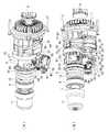
図1は、ハンマードリルの一例を示す一部縦断面図で、ハンマードリル1は、ハウジング2の前方(図1の左側)に、前端にビット4を装着可能なツールホルダ3を回転可能に軸支する一方、後方に、出力軸6を前方に向けたモータ5を収容している。
ツールホルダ3は、中間部7がハウジング2の前端でボールベアリング8に、後方の大径部9がハウジング2内後方に組み付けられたインナーハウジング10に夫々回転可能に軸支される筒状体で、ハウジング2から突出した前端には、差し込まれたビット4を着脱操作する操作スリーブ11が設けられている。また、大径部9の外周には、ギヤ12が外装されている。このギヤ12は、前方側で大径部9に外装されたコイルバネ13によって後方へ付勢され、ギヤ12の後方で大径部9に固定状態で外装されたストッパリング14に当接して位置決めされ、周方向で所定間隔をおいて保持したボール15を、ストッパリング14の凹部16に嵌合させてコイルバネ13との間に介在させたワッシャー17で押圧することで、回転が規制されるようになっている。すなわち、コイルバネ13の付勢力を上回る負荷がギヤ12に加わった場合は、ボール15が凹部16を乗り越えてギヤ12が空転することで、ツールホルダ3への回転伝達を遮断するトルクリミッタを形成したものである。Hereinafter, embodiments of the present invention will be described with reference to the drawings.
FIG. 1 is a partial longitudinal sectional view showing an example of a hammer drill. The hammer drill 1 has a
The
また、ツールホルダ3の中間部7内には、ビット4の後方に位置する中間子としてのインパクトボルト18が前後移動可能に収容されて、その後方で大径部9内には、インパクトボルト18の後退位置を規制する受けリング19とワッシャー20、空打ちの際に後述するストライカ24の前端を把持可能なOリングを内周に備えた把持リング21が夫々収容されている。
さらに、大径部9の後方には、打撃機構が備えられている。この打撃機構は、前方を開口して大径部9に遊挿される筒状のピストンシリンダ22と、そのピストンシリンダ22内に空気室23を介して前後移動可能に収容された打撃子としてのストライカ24とを有するもので、ピストンシリンダ22が大径部9内を往復動することで、空気バネの作用によってストライカ24を連動させ、インパクトボルト18の後端を打撃可能となっている。Further, an
Further, a striking mechanism is provided behind the
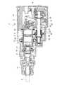
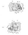
一方、ハウジング2内で出力軸6の下方には、図2,3にも示すように、中間軸25が、前後のボールベアリング26,27によってツールホルダ3及び出力軸6と平行に軸支され、後端に設けた第1ギヤ28を出力軸6に噛合させている。この中間軸25の中間部位には、スプライン歯29が形成されて、その前方でボールベアリング26との間には、回転伝達部材としての第2ギヤ30が中間軸25と別体回転可能に外装されて、ツールホルダ3側のギヤ12と噛合している。さらに、スプライン歯29の後方でボールベアリング27との間には、打撃伝達部材としてのボススリーブ31が、中間軸25と別体回転可能に外装されて、ボススリーブ31の外周に、軸線を傾けたスワッシュベアリング32が回転可能に外嵌されて、スワッシュベアリング32の上部に突設した連結アーム33の上端が、ボール34を介してピストンシリンダ22の後端で回転可能に保持されている。よって、ボススリーブ31が回転すると、スワッシュベアリング32が図1〜3に示すように前後に軸線を傾動させ、連結アーム33を前後に揺動させてピストンシリンダ22を往復動させることになる。On the other hand, below the
そして、中間軸25のスプライン歯29には、クラッチ部材としてのスリーブ状のクラッチ35がスプライン結合されて、中間軸25と一体回転可能且つ前後方向へスライド可能となっている。このクラッチ35の前面には、第2ギヤ30の後面に設けられた係合爪38,38に係合可能なクラッチ爪36,36が形成される一方、後面には、ボススリーブ31の前面に設けられた係合爪39,39に係合可能なクラッチ爪37,37が形成されて、前後のスライド位置により、第2ギヤ30及びボススリーブ31との一方又は双方と係脱可能となっている。すなわち、前進位置では第2ギヤ30のみと係合して中間軸25と回転方向で一体化させ、後退位置ではボススリーブ31のみと係合して中間軸25と回転方向で一体化させ、中間位置では第2ギヤ30及びボススリーブ31の双方と係合して中間軸25と回転方向で一体化させるものである。40は、クラッチ35の外周面で中央部に周設された被係合部としてのフランジである。 A sleeve-
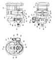
また、クラッチ35の上方には、連係部材としての第1連係板41及び第2連係板42が設けられている。この両連係板41,42は、図5にも示すように、インナーハウジング10の前面から前方へ突設され、大径部9の周面に沿って所定間隔へ配置されたガイド部材としての3本のガイド軸47〜49によって前後方向へスライド可能に支持される。このうち第1連係板41は、第1ガイド軸47から第2ガイド軸48へ大径部9の周面に沿って湾曲状に形成され、上端で折り曲げ形成したコ字状部43の端縁の切欠が第1ガイド軸47に貫通されると共に、中間が第2ガイド軸48に貫通されて、逆L字状に折曲された連係片44がフランジ40の後面側に位置している。 Further, a
一方、第2連係板42は、第2ガイド軸48から第3ガイド軸49へ大径部9の周面に沿って湾曲状に形成され、第3ガイド軸49側の端部で折り曲げ形成したコ字状部45が第3ガイド軸49に貫通されると共に、第2ガイド軸48側の端部が、第1連係板41よりも後方側で第2ガイド軸48に貫通され、当該端部の下方に延設される連係片46が、側面視で第1連係板41の連係片44と交差してフランジ40の前面側に位置している。
さらに、第2ガイド軸48において、第1連係板41と第2連係板42との間には、弾性部材としてのコイルバネ50が外装されている。これにより、第1連係板41と第2連係板42とは互いに相反方向へ付勢され、交差してフランジ40の前後に位置する連係片44と連係片46とは、逆に互いに接近する方向へ付勢されて、フランジ40を挟持することになる。On the other hand, the
Further, in the
51は、第2ギヤ30の前方側に外装された回転ロック部材としてのロックプレートで、前後方向にスライド可能で、後退位置では、第2ギヤ30への外装部内周縁に形成された切欠52,52・・が、第2ギヤ30の後方周縁で放射状に形成されたロック歯53,53・・と嵌合可能となって、その前方でハウジング2内面との間に設けたコイルバネ54により、後方へ付勢されている。また、ロックプレート51の下端には、後方へ向けて延設部55が延設されており、延設部55から上方に切り起こし成形したストッパ片56が、クラッチ35のフランジ40の前方に位置して、後述するクラッチ35のスライドによってストッパ片56がフランジ40と当接可能となっている。さらに、ロックプレート51の側縁には、連係片44に向けてロック片57が延設されている。
そして、ハウジング2には、操作部材となる操作レバー58が設けられている。この操作レバー58は、ハウジング2へ回転可能に嵌着される円盤部59と、その円盤部59にハウジング2の外面側で連結されたレバー部60とからなり、円盤部59におけるハウジング2内部側の内面には、長さの異なる第1、第2ピン61,62が夫々点対称に突設されている。このうち長い方の第1ピン61は、第1連係板41の連係片44と第2連係板42の連係片46との間に、短い方の第2ピン62は、連係片44とロックプレート51のロック片57との間に夫々突出している。よって、レバー部60の回転操作に伴う回転で第1、第2ピン61,62が前後方向の位置を変化させると、これに係合する連係片44,46を介してクラッチ35が、ロック片57を介してロックプレート51が夫々スライドすることになる。 The
以上の如く構成されたハンマードリル1においては、図4〜6に示すようにレバー部60が前方側へ傾倒する操作位置では、第1ピン61は最も前方寄りに位置し、第2ピン62は最も後方寄りに位置する。よって、第1、第2連係板41,42は共に前進位置へスライドし、連係片44,46が挟持するフランジ40を介してクラッチ35を前進位置へスライドさせ、クラッチ35の前面側のクラッチ爪36を第2ギヤ30の係合爪38と係合させるドリルモードとなる。このとき、後方へ付勢されるロックプレート51は、ロック片57が第2ピン62に当接して、第2ギヤ30のロック歯53と嵌合しない位置で停止している。
この切替操作の際、クラッチ爪36と係合爪38との位相が合わず、当接状態となっても、第1ピン61はそのまま前方寄りに移動し、コイルバネ50を圧縮させて第2連係板42のみを前進位置へスライドさせる。従って、クラッチ35には第1連係板41を介してコイルバネ50による前方への付勢力が働き、後述する中間軸25の回転でクラッチ35が回転してクラッチ爪36と係合爪38との位相が合うと、クラッチ35が前進位置へスライドして第2ギヤ30と連結することになる。In the hammer drill 1 configured as described above, as shown in FIGS. 4 to 6, in the operation position in which the
During this switching operation, even if the
このドリルモードでビット4をツールホルダ3に装着してモータ5を駆動させると、中間軸25が回転し、その回転がクラッチ35及び第2ギヤ30、ギヤ12を介してツールホルダ3に伝わり、ビット4を回転させる。一方、前進したクラッチ35が離れたボススリーブ31には回転が伝わらないため、ピストンシリンダ22は往復動しない。よって、ビット4は回転のみ行うこととなる。 When the bit 4 is mounted on the
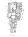
次に、図7〜9に示すように、レバー部60が略上向きとなるように操作レバー58を右回転させると、第1ピン61も右回転して後方側へ移動するため、第1、第2連係板41,42が後方へスライドしてクラッチ35を中間位置までスライドさせる。よって、第2ギヤ30との連結を維持したままクラッチ35の後面側のクラッチ爪37をボススリーブ31の係合爪39と係合させるハンマードリルモードとなる。このボススリーブ31との係合の際に爪同士に位相のズレがあって当接状態となっても、第2ギヤ30との係合の場合と同様に、第1ピン61によって先に第1連係板41がスライドしてコイルバネ50を圧縮させ、クラッチ35を後方へ付勢するため、クラッチ35の回転で爪同士の位相が合うと、クラッチ35が後退してボススリーブ31と直ちに連結することになる。 Next, as shown in FIGS. 7 to 9, when the
このハンマードリルモードでモータ5を駆動させると、中間軸25の回転がクラッチ35、第2ギヤ30、ギヤ12を介してツールホルダ3に伝わってビット4を回転させる一方、クラッチ35と連結されるボススリーブ31にも伝わる。よって、スワッシュベアリング32が揺動して連結アーム33がピストンシリンダ22を往復動させる。この動作により、ピストンシリンダ22内のストライカ24が連動して往復動し、ビット4の後端が当接するインパクトボルト18を打撃するため、ビット4には回転に加えて打撃が伝わることとなる。 When the
次に、図10〜12に示すように、レバー部60が後方へ傾倒するように操作レバー58を右回転させると、第1ピン61がさらに右回転して後方側へ移動するため、第1、第2連係板41,42と共にクラッチ35が後退位置までスライドして第2ギヤ30から離れるハンマーモードとなる。このとき、第2ピン62も右回転するが、後方への移動量は小さいので、ロックプレート51が後方へスライドしても第2ギヤ30のロック歯53には嵌合しない。
このハンマーモードでモータ5を駆動させると、中間軸25の回転は第2ギヤ30へ伝わらず、ツールホルダ3も回転しないが、ボススリーブ31は回転してピストンシリンダ22を往復動させるため、ビット4へは打撃のみが伝わることとなる。このとき、第2ギヤ30の回転はロックされていないので、ツールホルダ3の回転もフリーとなり、ビット4の軸線回りの角度を任意に変更できるニュートラル状態となる。Next, as shown in FIGS. 10 to 12, when the
When the
次に、図13〜15に示すように、さらにレバー部60が後方へ傾倒するように操作レバー58を右回転させると、第1ピン61は右回転しても後方側へは殆ど移動しないため、第1、第2連係板41,42及びクラッチ35の位置は変わらず、ハンマーモードは維持される。但し、第2ピン62は最も後方へ移動するので、ロックプレート51は、ストッパ片56がクラッチ35のフランジ40に当接するまでさらに後方へスライドし、ロック歯53と嵌合して第2ギヤ30の回転をロックする。
よって、モータ5を駆動させると、打撃機構のみが作動してビット4へは打撃のみが伝わることとなるが、ツールホルダ3の回転はロックされてビット4の角度も固定される回転ロック状態となる。Next, as shown in FIGS. 13 to 15, if the operating
Therefore, when the
このように、上記形態のハンマードリル1によれば、クラッチ35を弾性的に係合させる弾性手段を、中間軸25と平行に設けられた第1〜第3ガイド軸47〜49と、その第1〜第3ガイド軸47〜49に設けられ、クラッチ35と係合して一体にスライド可能な第1、第2連係板41,42と、その第1、第2連係板41,42を第1〜第3ガイド軸47〜49に沿って付勢するコイルバネ50とから形成したことで、ハウジング2内の既存のスペースを利用して、中間軸25上にコイルバネ等を用いることなく弾性手段が形成可能となる。よって、動作モードのスムーズな切替を維持しつつ、ハウジング2のコンパクト化やコストダウンが達成可能となる。
特にここでは、前後一対の第1、第2連係板41,42を設け、その間にコイルバネ50を介在させて第1、第2連係板41,42を互いに相反方向へ付勢すると共に、第1、第2連係板41,42を互いに交差させてクラッチ35の外周に設けたフランジ40と操作レバー58の第1ピン61とを挟持させたことで、1つのコイルバネ50を利用してクラッチ35が第2ギヤ30とボススリーブ31との何れに係合する際にも弾性的な係合が得られる合理的な構成となる。Thus, according to the hammer drill 1 of the said form, the elastic means which elastically engages the clutch 35 is provided with the 1st-3rd guide shafts 47-49 provided in parallel with the
In particular, here, a pair of front and rear first and
また、ハウジング2内に、前後方向へスライド可能で、クラッチ35がボススリーブ31のみと係合した状態での操作レバー58の操作により、第2ギヤ30と係脱してその回転のロックとその解除とを選択可能なロックプレート51を設けたことで、ハンマーモードにおいてツールホルダ3及びビット4のニュートラル状態と回転ロック状態との選択が可能となり、より使い勝手が良好となる。
さらに、ロックプレート51をコイルバネ54によって後方へ付勢すると共に、ロックプレート51に、第2ギヤ30との係合状態でクラッチ35のフランジ40に当接するストッパ片56を設けたことで、ロックプレート51の回転ロック状態への位置決めが確実になされる。Further, when the
Further, the
なお、ガイド部材の数は上記形態に限らず、例えば第3ガイド軸をなくして第1、第2ガイド軸で両連係板のスライドをガイドするようにして、ガイド軸の数を減らしたりしてもよい。また、ガイド部材の設置場所も、ツールホルダの外側に限らず、ハウジング内でのデッドスペースを利用できれば適宜変更可能である。勿論ガイド部材は前方から後方へ突出させてもよいし、軸体に限らず、板体等を採用しても差し支えない。
さらに、連係部材の形態も上記連係板に限らず、ガイド軸に遊挿させる筒状体を形成してスライド可能としたり等、適宜設計変更可能である。
加えて、連係部材とクラッチとの係合も、上記形態のようなフランジでなく、クラッチの周面に凹設した溝を利用することもできるし、弾性部材も、コイルバネに限らず、板バネや皿バネ等の他の部材を採用することが可能である。Note that the number of guide members is not limited to the above form. For example, the number of guide shafts may be reduced by eliminating the third guide shaft and guiding the slides of both linkage plates with the first and second guide shafts. Also good. Further, the installation location of the guide member is not limited to the outside of the tool holder, and can be changed as appropriate if a dead space in the housing can be used. Of course, the guide member may protrude from the front to the rear, and is not limited to the shaft body, and a plate body or the like may be employed.
Further, the form of the linking member is not limited to the above linking plate, and the design can be changed as appropriate, such as forming a cylindrical body to be loosely inserted into the guide shaft and making it slidable.
In addition, the engagement between the linkage member and the clutch is not a flange as in the above embodiment, but a groove provided in the circumferential surface of the clutch can be used, and the elastic member is not limited to a coil spring, but is also a leaf spring. It is possible to adopt other members such as a disc spring.
一方、上記形態では、回転ロック部材を設けてハンマーモードでのニュートラル状態と回転ロック状態とを選択できるようにしているが、この回転ロック部材をなくしてハンマーモードはニュートラル状態のみとしても差し支えない。
On the other hand, in the above-described embodiment, the rotation lock member is provided so that the neutral state and the rotation lock state in the hammer mode can be selected. However, the hammer mode may be set to the neutral state without the rotation lock member.
1・・ハンマードリル、2・・ハウジング、3・・ツールホルダ、4・・ビット、5・・モータ、6・・出力軸、10・・インナーハウジング、18・・インパクトボルト、22・・ピストンシリンダ、23・・空気室、24・・ストライカ、25・・中間軸、28・・第1ギヤ、30・・第2ギヤ、31・・ボススリーブ、32・・スワッシュベアリング、33・・連結アーム、35・・クラッチ、40・・フランジ、41・・第1連結板、42・・第2連結板、44,46・・連係片、47・・第1ガイド軸、48・・第2ガイド軸、49・・第3ガイド軸、50・・コイルバネ、51・・ロックプレート、56・・ストッパ片、57・・ロック片、58・・操作レバー、60・・レバー部、61・・第1ピン、62・・第2ピン。 1 .... hammer drill, 2..housing, 3..tool holder, 4..bit, 5..motor, 6..output shaft, 10..inner housing, 18..impact bolt, 22..piston cylinder .., 23..Air chamber, 24..Strike, 25..Intermediate shaft, 28..First gear, 30..Second gear, 31..Boss sleeve, 32..Swash bearing, 33..Connection arm, 35..Clutch, 40..Flange, 41..First connecting plate, 42..Second connecting plate, 44, 46..Linking piece, 47..First guide shaft, 48..Second guide shaft, 49 .. Third guide shaft, 50 .. Coil spring, 51 .. Lock plate, 56 .. Stopper piece, 57 .. Lock piece, 58 .. Operation lever, 60 .. Lever part, 61 .. First pin, 62 .. Second pin.
Claims (3)
Translated fromJapanese前記弾性手段を、前記中間軸と平行に設けられたガイド部材と、そのガイド部材に設けられ、前記クラッチ部材と係合して一体にスライド可能な連係部材と、その連係部材を前記ガイド部材に沿って付勢する弾性部材とから形成する一方、前記連係部材を前後一対設け、その間に前記弾性部材を介在させて前記両連係部材を互いに相反方向へ付勢すると共に、前記両連係部材を互いに交差させて前記クラッチ部材の外周に設けた被係合部と前記操作部材とを挟持させたことを特徴とするハンマードリル。A tool holder capable of mounting a bit at the front end is rotatably supported at the front in the housing, and the bit striking mechanism is provided behind the tool holder, while a motor is arranged at the rear in the housing. The intermediate shaft that is rotationally transmitted from the output shaft of the motor is supported in parallel with the tool holder, and the forward rotation of the intermediate shaft is transmitted to the tool holder side by rotation in front of the intermediate shaft. A transmission member is provided on the rear side so that a rotation transmission member that converts the rotation of the intermediate shaft into a longitudinal motion by rotation and transmits it to the striking mechanism is rotatable separately from the intermediate shaft. A clutch member that can rotate integrally with the intermediate shaft and slide in the front-rear direction is provided between the transmission member and the clutch member. And an elastic means for elastically engaging the clutch member with the rotation transmission member and / or the impact transmission member when sliding is provided. A hammer drill,
The elastic means includes a guide member provided in parallel with the intermediate shaft, a linkage member provided on the guide member, which can be slid integrally with the clutch member, and the linkage member as the guide member. And apair of front and rear link members, and the elastic members are interposed therebetween to bias the link members in opposite directions, and the link members are connected to each other. A hammer drill characterized in thatthe engaged portion provided on the outer periphery of the clutch member and the operation member are sandwiched and held .
Priority Applications (4)
| Application Number | Priority Date | Filing Date | Title |
|---|---|---|---|
| JP2007121011AJP5015653B2 (en) | 2007-05-01 | 2007-05-01 | Hammer drill |
| CN2008100896199ACN101298137B (en) | 2007-05-01 | 2008-04-10 | Electric hammer |
| EP08007598AEP1987925B1 (en) | 2007-05-01 | 2008-04-18 | Hammer drill |
| US12/081,653US7748472B2 (en) | 2007-05-01 | 2008-04-18 | Hammer drill |
Applications Claiming Priority (1)
| Application Number | Priority Date | Filing Date | Title |
|---|---|---|---|
| JP2007121011AJP5015653B2 (en) | 2007-05-01 | 2007-05-01 | Hammer drill |
Publications (3)
| Publication Number | Publication Date |
|---|---|
| JP2008272901A JP2008272901A (en) | 2008-11-13 |
| JP2008272901A5 JP2008272901A5 (en) | 2010-01-21 |
| JP5015653B2true JP5015653B2 (en) | 2012-08-29 |
Family
ID=39638866
Family Applications (1)
| Application Number | Title | Priority Date | Filing Date |
|---|---|---|---|
| JP2007121011AExpired - Fee RelatedJP5015653B2 (en) | 2007-05-01 | 2007-05-01 | Hammer drill |
Country Status (4)
| Country | Link |
|---|---|
| US (1) | US7748472B2 (en) |
| EP (1) | EP1987925B1 (en) |
| JP (1) | JP5015653B2 (en) |
| CN (1) | CN101298137B (en) |
Families Citing this family (19)
| Publication number | Priority date | Publication date | Assignee | Title |
|---|---|---|---|---|
| DE102008040767A1 (en)* | 2008-07-28 | 2010-02-04 | Robert Bosch Gmbh | impact device |
| EP2216114B1 (en)* | 2009-02-05 | 2013-08-28 | Techtronic Power Tools Technology Limited | Power tool chuck assembly with hammer mechanism |
| JP5431000B2 (en)* | 2009-04-01 | 2014-03-05 | 株式会社マキタ | Hammer drill |
| DE102009027951A1 (en)* | 2009-07-23 | 2011-01-27 | Robert Bosch Gmbh | Hand tool machine, in particular battery-operated electric hand tool machine |
| CN101758486B (en)* | 2010-01-21 | 2011-09-28 | 浙江海王电器有限公司 | Light single-button multifunctional electric hammer |
| JP5518617B2 (en)* | 2010-08-02 | 2014-06-11 | 株式会社マキタ | Impact tool |
| DE102012209446A1 (en)* | 2012-06-05 | 2013-12-05 | Robert Bosch Gmbh | Hand machine tool device |
| US9630307B2 (en) | 2012-08-22 | 2017-04-25 | Milwaukee Electric Tool Corporation | Rotary hammer |
| CN103894983A (en)* | 2012-12-26 | 2014-07-02 | 株式会社牧田 | Hammer drill |
| CN104455397B (en)* | 2014-11-17 | 2016-09-14 | 张家港市创基机械设备制造有限公司 | Shifter in three function electric hammer |
| US10328560B2 (en)* | 2015-02-23 | 2019-06-25 | Brian Romagnoli | Multi-mode drive mechanisms and tools incorporating the same |
| US11052525B2 (en)* | 2016-03-03 | 2021-07-06 | Makita Corporation | Hammer drill |
| CN106826695A (en)* | 2016-12-23 | 2017-06-13 | 永康市杰拉华工具有限公司 | A kind of function electric hammer of single button four |
| KR20200102589A (en) | 2019-02-21 | 2020-09-01 | 계양전기 주식회사 | Electric Hammer drill |
| US12005556B2 (en)* | 2019-03-28 | 2024-06-11 | Koki Holdings Co., Ltd. | Driving work machine |
| EP3789161A1 (en)* | 2019-09-06 | 2021-03-10 | Hilti Aktiengesellschaft | Hand machine tool |
| JP7696237B2 (en)* | 2021-06-10 | 2025-06-20 | 株式会社マキタ | Rotary impact tool |
| JP7716943B2 (en)* | 2021-09-22 | 2025-08-01 | 株式会社マキタ | power tools |
| CN116352658A (en)* | 2021-12-20 | 2023-06-30 | 南京泉峰科技有限公司 | Electric tool and hammer drill |
Family Cites Families (24)
| Publication number | Priority date | Publication date | Assignee | Title |
|---|---|---|---|---|
| US3685594A (en)* | 1970-08-03 | 1972-08-22 | Rockwell Mfg Co | Rotary hammer or the like |
| US3734515A (en)* | 1971-01-29 | 1973-05-22 | Thor Power Tool Co | Power wrench with interchangeable adapters |
| JPS5969808U (en)* | 1982-09-07 | 1984-05-11 | 株式会社マキタ | Vibratory device in vibrating drill |
| DE3311265A1 (en)* | 1983-03-28 | 1984-10-11 | Hilti Ag, Schaan | ELECTROPNEUMATIC DRILL AND CHISEL HAMMER |
| DE3506695A1 (en)* | 1985-02-26 | 1986-08-28 | Robert Bosch Gmbh, 7000 Stuttgart | DRILLING HAMMER |
| USRE35372E (en)* | 1988-06-07 | 1996-11-05 | S-B Power Tool Company | Apparatus for driving a drilling or percussion tool |
| NL8801466A (en)* | 1988-06-07 | 1990-01-02 | Emerson Electric Co | DEVICE FOR DRIVING A DRILL AND / OR IMPACT TOOL. |
| US4991472A (en)* | 1988-11-04 | 1991-02-12 | James Curtis Hilliard | D.C. direct drive impact wrench |
| JP2828657B2 (en) | 1989-04-25 | 1998-11-25 | 松下電工株式会社 | Hammer drill |
| DE4213291C2 (en) | 1992-04-23 | 1997-12-04 | Atlas Copco Elektrowerkzeuge | Gear device of a hand-held rotary hammer machine |
| JPH06210507A (en)* | 1993-01-18 | 1994-08-02 | Makita Corp | Motive power changeover mechanism in rotary tool |
| DE4406841C1 (en)* | 1994-03-02 | 1995-04-20 | Metabowerke Kg | Hammer drill |
| JP3688943B2 (en)* | 1999-08-26 | 2005-08-31 | 株式会社マキタ | Hammer drill |
| CN2426395Y (en)* | 2000-06-08 | 2001-04-11 | 常州合力电器有限公司 | Multifunctional electric hammer |
| DE10111746A1 (en)* | 2001-03-12 | 2002-09-19 | Hilti Ag | Shift transmission means for the combined shifting of a transmission |
| GB0213289D0 (en)* | 2002-06-11 | 2002-07-24 | Black & Decker Inc | Rotary hammer |
| GB0213464D0 (en)* | 2002-06-12 | 2002-07-24 | Black & Decker Inc | Hammer |
| GB2394516A (en)* | 2002-10-23 | 2004-04-28 | Black & Decker Inc | Power tool |
| JP3976187B2 (en)* | 2002-11-20 | 2007-09-12 | 株式会社マキタ | Hammer drill |
| DE102004045117A1 (en) | 2004-09-17 | 2006-03-23 | Robert Bosch Gmbh | switching device |
| DE102004052329A1 (en)* | 2004-10-27 | 2006-05-04 | Kress-Elektrik Gmbh & Co. Elektromotorenfabrik | Synchronization and switching unit for one-button selector switch and power tool with synchronization and switching unit |
| US7377331B2 (en)* | 2005-04-06 | 2008-05-27 | Power Network Industry Co., Ltd. | Damping driving axle |
| DE102005041447A1 (en)* | 2005-08-31 | 2007-03-01 | Robert Bosch Gmbh | Hammer drill, comprises intermediate shaft designed as plain cylindrical element holding driving wheel, driven wheel, and slide bearing |
| CN2920563Y (en)* | 2006-07-11 | 2007-07-11 | 王文江 | Light single-span four function electric hammer |
- 2007
- 2007-05-01JPJP2007121011Apatent/JP5015653B2/ennot_activeExpired - Fee Related
- 2008
- 2008-04-10CNCN2008100896199Apatent/CN101298137B/ennot_activeExpired - Fee Related
- 2008-04-18USUS12/081,653patent/US7748472B2/ennot_activeExpired - Fee Related
- 2008-04-18EPEP08007598Apatent/EP1987925B1/ennot_activeCeased
Also Published As
| Publication number | Publication date |
|---|---|
| JP2008272901A (en) | 2008-11-13 |
| CN101298137A (en) | 2008-11-05 |
| EP1987925A1 (en) | 2008-11-05 |
| US7748472B2 (en) | 2010-07-06 |
| EP1987925B1 (en) | 2011-06-08 |
| US20080271905A1 (en) | 2008-11-06 |
| CN101298137B (en) | 2012-11-14 |
Similar Documents
| Publication | Publication Date | Title |
|---|---|---|
| JP5015653B2 (en) | Hammer drill | |
| JP5116029B2 (en) | Hammer drill | |
| JP3976187B2 (en) | Hammer drill | |
| JP5128391B2 (en) | Hammer drill | |
| JP4981506B2 (en) | Hammer drill | |
| CN100354074C (en) | electrical tools | |
| EP1157788A2 (en) | Rotary hammer mode change mechanism | |
| JP2001062621A (en) | Hammer drill | |
| EP1950008A1 (en) | Hammer drill | |
| JP2006026854A (en) | Electric hammer drill | |
| JP5171085B2 (en) | Impact tool | |
| CN100544897C (en) | Electric tool | |
| JP5431000B2 (en) | Hammer drill | |
| JP4568600B2 (en) | Hammer drill | |
| JPH06262413A (en) | Power switching mechanism in rotary tool | |
| JP2017154229A (en) | Hammer drill | |
| JP3756725B2 (en) | Impact tool | |
| JP4746920B2 (en) | Electric tool | |
| JP2024168766A (en) | Impact tools | |
| JP2022128135A (en) | Power tool | |
| CN119016764A (en) | Power Tools | |
| JP2012171063A (en) | Impact tool |
Legal Events
| Date | Code | Title | Description |
|---|---|---|---|
| A521 | Written amendment | Free format text:JAPANESE INTERMEDIATE CODE: A523 Effective date:20091127 | |
| A621 | Written request for application examination | Free format text:JAPANESE INTERMEDIATE CODE: A621 Effective date:20091127 | |
| A977 | Report on retrieval | Free format text:JAPANESE INTERMEDIATE CODE: A971007 Effective date:20111004 | |
| A131 | Notification of reasons for refusal | Free format text:JAPANESE INTERMEDIATE CODE: A131 Effective date:20111018 | |
| TRDD | Decision of grant or rejection written | ||
| A01 | Written decision to grant a patent or to grant a registration (utility model) | Free format text:JAPANESE INTERMEDIATE CODE: A01 Effective date:20120508 | |
| A01 | Written decision to grant a patent or to grant a registration (utility model) | Free format text:JAPANESE INTERMEDIATE CODE: A01 | |
| A61 | First payment of annual fees (during grant procedure) | Free format text:JAPANESE INTERMEDIATE CODE: A61 Effective date:20120607 | |
| FPAY | Renewal fee payment (event date is renewal date of database) | Free format text:PAYMENT UNTIL: 20150615 Year of fee payment:3 | |
| R150 | Certificate of patent or registration of utility model | Ref document number:5015653 Country of ref document:JP Free format text:JAPANESE INTERMEDIATE CODE: R150 Free format text:JAPANESE INTERMEDIATE CODE: R150 | |
| R250 | Receipt of annual fees | Free format text:JAPANESE INTERMEDIATE CODE: R250 | |
| R250 | Receipt of annual fees | Free format text:JAPANESE INTERMEDIATE CODE: R250 | |
| R250 | Receipt of annual fees | Free format text:JAPANESE INTERMEDIATE CODE: R250 | |
| R250 | Receipt of annual fees | Free format text:JAPANESE INTERMEDIATE CODE: R250 | |
| R250 | Receipt of annual fees | Free format text:JAPANESE INTERMEDIATE CODE: R250 | |
| R250 | Receipt of annual fees | Free format text:JAPANESE INTERMEDIATE CODE: R250 | |
| LAPS | Cancellation because of no payment of annual fees |