JP5010944B2 - Ultrasonic flaw detector - Google Patents
Ultrasonic flaw detectorDownload PDFInfo
- Publication number
- JP5010944B2 JP5010944B2JP2007050266AJP2007050266AJP5010944B2JP 5010944 B2JP5010944 B2JP 5010944B2JP 2007050266 AJP2007050266 AJP 2007050266AJP 2007050266 AJP2007050266 AJP 2007050266AJP 5010944 B2JP5010944 B2JP 5010944B2
- Authority
- JP
- Japan
- Prior art keywords
- inspected
- ultrasonic
- ultrasonic flaw
- flaw detection
- probe
- Prior art date
- Legal status (The legal status is an assumption and is not a legal conclusion. Google has not performed a legal analysis and makes no representation as to the accuracy of the status listed.)
- Active
Links
Images


Landscapes
- Investigating Or Analyzing Materials By The Use Of Ultrasonic Waves (AREA)
Description
Translated fromJapanese本発明は、配管などの溶接構造物(被検査構造物)に発生したひびなどの欠陥の大きさや長さを測定する超音波探傷装置に関する。The present inventionrelates to an ultrasonic flaw detection apparatus for measuring the size and length of defects such as cracks occurring in welded structures such as piping (inspection structures).
現状、溶接構造物(被検査構造物)に発生したひびなどの欠陥の大きさや長さを検査するときには、超音波探傷試験用探触子と溶接構造物の表面とを接触させて検査する接触法などが用いられている。そして、溶接構造物(被検査構造物)は、このような接触法により得られた超音波探傷試験結果を解析、評価することにより、検査されている。 Currently, when inspecting the size and length of defects such as cracks in welded structures (structures to be inspected), contact is performed by contacting the probe for ultrasonic testing and the surface of the welded structure. Laws are used. The welded structure (inspected structure) is inspected by analyzing and evaluating the ultrasonic flaw detection test results obtained by such a contact method.
また、現状のシュラウドやシュラウドサポートなどの沸騰水型および加圧水型原子力発電所の炉内構造物などの複数の溶接線を含んだ溶接構造物の超音波探傷試験においては、遠隔駆動装置に超音波探傷試験用探触子を1台搭載し、1溶接線毎に超音波探傷試験を行っている。 In ultrasonic testing of welded structures that include multiple weld lines such as in-core structures of boiling water and pressurized water nuclear power plants such as the current shroud and shroud support, One probe for flaw detection test is installed, and an ultrasonic flaw detection test is performed for each weld line.
溶接構造物(被検査構造物)に発生したひびなどの欠陥の大きさや長さを検査する場合において、特に、凸凹が大きいなど複雑な表面からなる溶接構造物を検査する場合には、接触法では超音波探傷試験用探触子を位置決め精度良く設置することは困難である。また、溶接構造物の表面の形状による影響により、探傷を測定する精度が低くなる可能性がある。 When inspecting the size and length of defects such as cracks in welded structures (structures to be inspected), especially when inspecting welded structures with complex surfaces such as large irregularities, the contact method Therefore, it is difficult to install an ultrasonic flaw detection test probe with high positioning accuracy. Moreover, the accuracy of measuring flaws may be lowered due to the influence of the surface shape of the welded structure.
また、複数の溶接線を含んだ溶接構造物の超音波探傷試験を実施する場合には、その都度、遠隔駆動装置の段取り換えを行う必要があり、工期延長の一要因となっている。 Further, when an ultrasonic flaw detection test is performed on a welded structure including a plurality of weld lines, it is necessary to change the remote drive device each time, which is a factor in extending the work period.
本発明は、このような点を考慮してなされたものであり、被検査構造物の表面の凸凹の影響を受けずに超音波探傷試験を実施し、精度の良い測定結果を得ることができる超音波探傷装置を提供することを目的とする。The present invention has been made in consideration of such points, and can perform an ultrasonic flaw detection test without being affected by the unevenness of the surface of the structure to be inspected, and obtain an accurate measurement result. An object isto provide an ultrasonic flaw detector.
本発明は、水中に配置された被検査構造物に発生した欠陥を検査する超音波探傷装置において、
被検査構造物の表面上に配置された保持機構と、
保持機構により被検査構造物の表面に対して非接触状態で保持されるとともに、一次元状または二次元状に配置された複数の超音波探傷試験用探触子を有するフェーズドアレイ探触子と、
超音波探傷試験用探触子からの信号に基づいて検出された被検査構造物の表面形状と、超音波探傷試験用探触子から発信された超音波の発信方向とに基づいて、被検査構造物の表面に対する超音波の入射角を検出する探傷器と、
を備え、
超音波探傷試験用探触子の各々が、超音波を被検査構造物内に発信するとともに、被検査構造物の欠陥から反射された超音波を受信することを特徴とする超音波探傷装置である。The present invention is an ultrasonic flaw detector for inspecting a defect generated in a structure to be inspected disposed in water.
A holding mechanism disposed on the surface of the structure to be inspected;
A phased array probe that is held in a non-contact state with respect to the surface of the structure to be inspected by a holding mechanism and has a plurality of ultrasonic flaw detection probes arranged in a one-dimensional or two-dimensional manner; ,
Inspected based on the surface shape of the inspected structure detected based on the signal from the ultrasonic flaw detection test probe and the transmission direction of the ultrasonic wave transmitted from the ultrasonic flaw detection test probe A flaw detector for detecting the incident angle of the ultrasonic wave to the surface of the structure;
With
Each of the ultrasonic flaw detection test probes transmits an ultrasonic wave into a structure to be inspected and receives an ultrasonic wave reflected from a defect in the structure to be inspected. is there.
本発明は、保持機構が、フェーズドアレイ探触子と被検査構造物の表面との距離を遠隔操作により調整する調整機構を有することを特徴とする超音波探傷装置である。 The present invention is the ultrasonic flaw detector characterized in that the holding mechanism has an adjustment mechanism that adjusts the distance between the phased array probe and the surface of the structure to be inspected by remote control.
本発明は、気体中に配置された被検査構造物に発生した欠陥を検査する超音波探傷装置において、
被検査構造物の表面上に配置された保持機構と、
保持機構により被検査構造物の表面に対して非接触状態で保持されるとともに、一次元状または二次元状に配置された複数の超音波探傷試験用探触子を有するフェーズドアレイ探触子と、
フェーズドアレイ探触子を覆って配置され、内部に水が充填されたチャンバー機構と、
超音波探傷試験用探触子からの信号に基づいて検出された被検査構造物の表面形状と、超音波探傷試験用探触子から発信された超音波の発信方向とに基づいて、被検査構造物の表面に対する超音波の入射角を検出する探傷器と、
を備え、
超音波探傷試験用探触子の各々が、超音波を被検査構造物内に発信するとともに、被検査構造物の欠陥から反射された超音波を受信することを特徴とする超音波探傷装置である。The present invention is an ultrasonic flaw detection apparatus for inspecting defects generated in a structure to be inspected arranged in a gas.
A holding mechanism disposed on the surface of the structure to be inspected;
A phased array probe that is held in a non-contact state with respect to the surface of the structure to be inspected by a holding mechanism and has a plurality of ultrasonic flaw detection probes arranged in a one-dimensional or two-dimensional manner; ,
A chamber mechanism placed over the phased array probe and filled with water;
Inspected based on the surface shape of the inspected structure detected based on the signal from the ultrasonic flaw detection test probe and the transmission direction of the ultrasonic wave transmitted from the ultrasonic flaw detection test probe A flaw detector for detecting the incident angle of the ultrasonic wave to the surface of the structure;
With
Each of the ultrasonic flaw detection test probes transmits an ultrasonic wave into a structure to be inspected and receives an ultrasonic wave reflected from a defect in the structure to be inspected. is there.
本発明によれば、超音波探傷試験用探触子の各々が、超音波を被検査構造物内に発信するとともに、被検査構造物の欠陥によって反射された超音波を受信するので、被検査構造物の表面の凸凹の影響を受けずに超音波探傷試験を実施し、精度の良い測定結果を得ることができる。また、各溶接線近傍に配置され、対応する溶接線を検査する目視点検用カメラ、超音波探傷試験用探触子、渦電流試験用探触子または放射線透過試験用探触子により、複数の溶接線を検査するときの検査時間を大幅に短縮することができる。 According to the present invention, each of the probes for ultrasonic flaw detection test transmits ultrasonic waves into the structure to be inspected and receives ultrasonic waves reflected by defects in the structure to be inspected. An ultrasonic flaw detection test can be performed without being affected by the unevenness of the surface of the structure, and an accurate measurement result can be obtained. Also, a plurality of visual inspection cameras, ultrasonic flaw detection test probes, eddy current test probes, or radiation transmission test probes that are arranged in the vicinity of each weld line and inspect the corresponding weld lines are used. The inspection time when inspecting the weld line can be greatly shortened.
第1の実施の形態
以下、本発明に係る超音波探傷装置の第1の実施の形態について、図面を参照して説明する。ここで、図1乃至図6は本発明の第1の実施の形態を示す図である。First Embodiment Hereinafter, afirst embodiment of an ultrasonic flaw detector according to the present invention will be described with reference to the drawings. Here, FIG. 1 thru | or FIG. 6 is a figure which shows the 1st Embodiment of this invention.
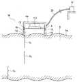
本実施の形態の超音波探傷装置は、図1に示すように、水Wの中に配置されたシュラウド、シュラウドサポート、ジェットポンプ、炉心スプレイ配管、給水スパージャ、制御棒駆動機構スタブチューブ、インコア検出案内管などの炉内構造物および再循環系(以下、PLRと言う)配管などの被検査構造物5に発生したひびなどの欠陥を検出するためのものである。 As shown in FIG. 1, the ultrasonic flaw detection apparatus according to the present embodiment includes a shroud, a shroud support, a jet pump, a core spray pipe, a water supply sparger, a control rod drive mechanism stub tube, and an in-core detection that are arranged in water W. This is to detect defects such as cracks generated in the in-furnace structure such as the guide tube and the structure to be inspected 5 such as the recirculation system (hereinafter referred to as PLR) piping.
ここで、ひびの種類としては、図1に示すように、超音波探傷試験用探触子1が存在する面(図1において上面)5aに開口面を有するひび(欠陥)D1、超音波探傷試験用探触子1が存在する面と逆の面(図1において下面)に開口面を有するひび(欠陥)D2、被検査構造物5に内在するひび(欠陥)D3がある。Here, as shown in FIG. 1, the crack type is a crack (defect) D1 having an opening surface on the surface (upper surface in FIG. 1) 5 a on which the
この超音波探傷装置は、図1に示すように、被検査構造物5の表面5a上に配置された水距離一定保持治具(保持機構)4と、水距離一定保持治具4により被検査構造物5の表面5aに対して非接触状態で一定の距離(水距離)を保って保持されるとともに、直線状(一次元状)またはマトリックス状(二次元状)に配置された複数の超音波探傷試験用探触子1を有するフェーズドアレイ探触子3(図2(a)(b)参照)と、フェーズドアレイ探触子3からの信号に基づいて、被検査構造物5の表面5a形状を表示(出力)する探傷器17とを備えている。なお、探傷器17は、ケーブル23を介して、フェーズドアレイ探触子3に接続されている。 As shown in FIG. 1, the ultrasonic flaw detector is inspected by a water distance constant holding jig (holding mechanism) 4 disposed on the
また、図1において、超音波探傷試験用探触子1の各々は、超音波を被検査構造物5内に発信するとともに、被検査構造物5に発生したひびなどの欠陥によって反射された超音波を受信する。 In FIG. 1, each of the ultrasonic flaw
また、図1において、水距離一定保持治具4は、フェーズドアレイ探触子3を駆動してフェーズドアレイ探触子3と被検査構造物5の表面5aとの距離を遠隔操作により調整する調整機構4aを有している。また、図1に示すように、水距離一定保持治具4は被検査構造物5の表面5aの凸凹に追従するために、走行車輪12および伸縮機構13を有している。 In FIG. 1, the water distance
また、図1に示す探傷器17は、超音波探傷試験用探触子1からの信号に基づいて検出された被検査構造物5の表面5aの形状と、超音波探傷試験用探触子1から発信された超音波の発信方向とに基づいて、被検査構造物5内で伝達される超音波の屈折角を算出する。 Further, the
なお、図1に示す超音波探傷装置の調整機構4aは、探傷器17から得られた被検査構造物5の表面5a形状に関する情報に基づいて、フェーズドアレイ探触子3を回動させることにより、超音波探傷試験用探触子1から被検査構造物5内に発信される超音波の入射角を調整することができる。 Note that the
次に、このような構成からなる本実施の形態の作用について述べる。 Next, the operation of the present embodiment having such a configuration will be described.
最初に、ひびD1,D2,D3の深さを算出する一般的な方法について、図3乃至図5を用いて説明する。First, a general method for calculating the depths of the cracks D1 , D2 , and D3 will be described with reference to FIGS.
まず、図3を用いて、超音波探傷試験用探触子1が存在する面に開口面を有するひびD1の深さを算出する方法について説明する。First, a method of calculating the depth of the crack D1 having an opening surface on the surface where the
図3において、水Wの中の超音波USiaの音速をVia、被検査構造物5内の超音波USraの音速をVra、被検査構造物5への超音波USiaの入射角をΘia、被検査構造物5の中での超音波USraの屈折角をΘraとすると、次の式(1)が成立する。
Via/sinΘia=Vra/sinΘra 式(1)
そして、このような式(1)に基づき、入射角Θiaから、超音波USraの被検査構造物5内における屈折角Θraを算出することができ、後述する式(4)によって、ひびの深さdを算出することができる。In FIG. 3, the sound velocity of the ultrasonic wave USia in the water W is Via , the sound velocity of the ultrasonic wave USra in the structure to be inspected 5 is Vra , and the incident angle of the ultrasonic wave USia to the
Via / sin Θia = Vra / sin Θra formula (1)
Then, based on the equation (1), the refraction angle Θra of the ultrasonic wave USra in the structure to be inspected 5 can be calculated from the incident angle Θia. The depth d of can be calculated.
次に、図4を用いて、超音波探傷試験用探触子1が存在する面と逆の面に開口面を有するひびD2の深さを算出する方法について説明する。Next, with reference to FIG. 4, a method for calculating the depth of crack D2 having an open face to face opposite surfaces of the
図4において、水Wの中の超音波USibの音速をVib、被検査構造物5内の超音波USrbの音速をVrb、被検査構造物5への超音波USibの入射角をΘib、被検査構造物5の中での屈折角をΘrbとすると、次の式(2)が成立する。
Vib/sinΘib=Vrb/sinΘrb 式(2)
そして、このような式(2)に基づき、入射角Θibから、超音波USrbの被検査構造物5内における屈折角Θrbを算出することができ、後述する式(4)によって、ひびの深さdを算出することができる。In FIG. 4, the sound velocity of the ultrasonic wave USib in the water W is Vib , the sound velocity of the ultrasonic wave USrb in the structure to be inspected 5 is Vrb , and the incident angle of the ultrasonic wave USib to the structure to be inspected 5. Is Θib , and the refraction angle in the inspected
Vib / sin Θib = Vrb / sin Θrb equation (2)
Based on the equation (2), the refraction angle Θrb of the ultrasonic wave USrb in the structure to be inspected 5 can be calculated from the incident angle Θib. The depth d of can be calculated.
次に、図5を用いて、被検査構造物5に内在するひびD3の深さを算出する方法について説明する。Next, a method for calculating the depth of the crack D3 present in the
図5において、水Wの中の超音波USicの音速をVic、被検査構造物5内の超音波USrcの音速をVrc、被検査構造物5への超音波USicの入射角をΘic、被検査構造物5の中での屈折角をΘrcとすると、次の式(3)が成立する。
Vic/sinΘic=Vrc/sinΘrc 式(3)
そして、このような式(3)に基づき、入射角Θicから、超音波USrcの被検査構造物5内における屈折角Θrcを算出することができ、後述する式(4)によって、ひびの深さdを算出することができる。In FIG. 5, the sound velocity of the ultrasonic wave USic in the water W is Vic , the sound velocity of the ultrasonic wave USrc in the
Vic / sinΘic = Vrc / sinΘrc equation (3)
Based on the equation (3), the refraction angle Θrc of the ultrasonic wave USrc in the structure to be inspected 5 can be calculated from the incident angle Θic. The depth d of can be calculated.
続いて、本実施の形態による超音波探傷装置を用いて、被検査構造物5に発生したひびの深さを検出する方法について、超音波探傷試験用探触子1が存在する面に開口面を有するひびD1を例にとって説明する。Subsequently, with respect to a method for detecting the depth of cracks generated in the
まず、超音波探傷装置が被検査構造物5の表面5a上に設置される(図6参照)。 First, an ultrasonic flaw detector is installed on the
次に、フェーズドアレイ探触子3の直線状またはマトリックス状に配置された複数の超音波探傷試験用探触子1(図2参照)から、水Wの中に超音波USiaが発信され、当該超音波USiaが被検査構造物5内に入射する(図6参照)。Next, an ultrasonic wave USia is transmitted into the water W from a plurality of ultrasonic flaw detection test probes 1 (see FIG. 2) arranged in a linear or matrix form of the phased array probe 3, The ultrasonic wave USia enters the inspected structure 5 (see FIG. 6).
次に、フェーズドアレイ探触子3の各超音波探傷試験用探触子1によって、被検査構造物5に発生したひびD1により反射された超音波USraが水Wを通過した後、受信される(図6参照)。このように、水浸法を用いることにより、被検査構造物5の表面5aの凸凹の影響を受けずに超音波探傷試験を実施することができる。このため、精度の良い測定結果を得ることができる。Next, the ultrasonic wave USra reflected by the crack D1 generated in the
次に、図6において、超音波探傷試験用探触子1により受信された超音波USraに関する信号が探傷器17に送信され、当該探傷器17によって表示される。具体的には、図6に示すように、複数の超音波探傷試験用探触子1のうち、n番目の超音波探傷試験用探触子1が検知したAスコープ信号Sa,nおよび(n+1)番目の超音波探傷試験用探触子1が検知したAスコープ信号Sa,n+1など全ての超音波探傷試験用探触子1が検知したAスコープ信号Saと、当該Aスコープ信号Saから探傷器17内で変換されたBスコープ信号Sbとが、探傷器17に表示される。Next, in FIG. 6, a signal related to the ultrasonic waveUSra received by the ultrasonic flaw
また、図6において、探傷器17により、超音波探傷試験用探触子1からの信号に基づいて検出された被検査構造物5の表面5aの形状と、超音波探傷試験用探触子1から発信された超音波USiaの発信方向とに基づいて、ひびD1の深さdを精度良く検出することができる。In FIG. 6, the shape of the
具体的には、図6において、探傷器17により、Bスコープ信号Sbにおける表面エコー30のずれ量QLおよびずれ量QWを計測される。そして、探傷器17により、このずれ量QLおよびずれ量QWから被検査構造物5の表面5aの傾斜角Θsが算出され、被検査構造物5の表面5aの実際の凸凹が検出される。そして、検出された被検査構造物5の表面5aの実際の凸凹と、超音波探傷試験用探触子1から発信された超音波USiaの発信方向とに基づいて、探傷器17により、被検査構造物5の表面5aに対する超音波USiaの入射角Θiaが正確に検出される。このため、上述した式(1)に基づいて、被検査構造物5内で伝達される超音波USraの屈折角Θraを正確に算出することができる。この結果、以下の式(4)によりひびD1の深さdを精度良く検出することができる。
d=L×cosΘra 式(4)Specifically, in FIG. 6, the
d = L × cosΘra formula (4)
ここで、Lは被検査構造物5内における超音波USraの路程を示しており、超音波USraの被検査構造物5の中における速度と、超音波USraが超音波探傷試験用探触子1により被検査構造物5内に入射された時間から、ひびD1で反射された後に超音波探傷試験用探触子1により受信されるまでの時間と、によって算出される。Here, L is shows the path length of the ultrasonic USra in the inspected
第2の実施の形態
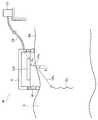
次に図7により本発明の第2の実施の形態について説明する。図7に示す第2の実施の形態は、気体中に配置された被検査構造物5に発生した欠陥を検査するための超音波探傷装置であり、フェーズドアレイ探触子3を覆って配置され、内部に水(図示せず)が充填されたチャンバー機構43をさらに備えたものであり、その他の構成は図1乃至図6に示す第1の実施の形態と略同一である。SecondEmbodiment Next, asecond embodiment of the present invention will be described with reference to FIG. The second embodiment shown in FIG. 7 is an ultrasonic flaw detector for inspecting a defect generated in a structure to be inspected 5 arranged in gas, and is arranged so as to cover the phased array probe 3. Further, a
図7に示す第2の実施の形態において、図1乃至図6に示す第1の実施の形態と同一部分には同一符号を付して詳細な説明は省略する。 In the second embodiment shown in FIG. 7, the same parts as those in the first embodiment shown in FIGS. 1 to 6 are denoted by the same reference numerals, and detailed description thereof is omitted.
図7に示すように、チャンバー機構43は、プローブフォルダー40により保持されている。このプローブフォルダー40は、水距離一定保持治具4も保持している。チャンバー機構43には、チャンバー機構43内に水を供給するポンプ39がホース38を介して連結されている。 As shown in FIG. 7, the
また、図7に示すように、プローブフォルダー40には、駆動用ベルト41が連結され、当該駆動用ベルト41には駆動用ベルト41を駆動する駆動機構44が連結されている。 As shown in FIG. 7, a driving
例えば、被検査構造物5としてPLR配管などの配管を検査する場合には、配管5の周方向にプローブフォルダー40を駆動させることにより、気中に存在する配管に対して水浸法を用いて超音波探傷することができる。 For example, when inspecting a pipe such as a PLR pipe as the
なお、駆動機構44には、駆動用モーター(図示せず)やプローブフォルダー40の位置検出用のエンコーダー(図示せず)が搭載されている。なお、このエンコーダーで検出されたプローブフォルダー40の位置に関する情報は、探傷器17によって表示されることが好ましい。 The
第3の実施の形態
次に図8および図9により本発明の第3の実施の形態について説明する。図8および図9に示す第3の実施の形態は、複数の溶接線46を含む被検査構造物5を検査するための検査装置であり、各溶接線46近傍に、対応する溶接線46を検査する超音波探傷試験用探触子1を有するフェーズドアレイ探触子3が設置されている。また、フェーズドアレイ探触子3には、リンク機構48を介して遠隔駆動装置50が接続されている。また、フェーズドアレイ探触子3には、フェーズドアレイ探触子3の超音波探傷試験用探触子1からの信号に基づいて被検査構造物5の表面5aの形状を表示(出力)する探傷器17が接続されている。Third Embodiment Next, athird embodiment of the present invention will be described with reference to FIGS. The third embodiment shown in FIG. 8 and FIG. 9 is an inspection apparatus for inspecting a
図8および図9に示す第3の実施の形態において、図1乃至図6に示す第1の実施の形態と同一部分には同一符号を付して詳細な説明は省略する。 In the third embodiment shown in FIGS. 8 and 9, the same parts as those in the first embodiment shown in FIGS. 1 to 6 are denoted by the same reference numerals, and detailed description thereof is omitted.
図8に示すように、各溶接線46に対して、伝播する超音波USの軌跡を勘案した上で、一次元状または二次元状に配置された複数の超音波探傷試験用探触子1を有するフェーズドアレイ探触子3(図2(a)(b)参照)が設置されている。 As shown in FIG. 8, a plurality of ultrasonic flaw
また、各フェーズドアレイ探触子3はリンク機構48を介して遠隔駆動装置50に接続されている。このため、遠隔駆動装置50の駆動に追従させて各フェーズドアレイ探触子3の超音波探傷試験用探触子1を駆動させることができる。 Each phased array probe 3 is connected to a
このように、各溶接線46近傍に、対応する溶接線46を検査する超音波探傷試験用探触子1が配置されているので、従来のように遠隔駆動装置50の段取り換えを行う必要がなく、かつ同時に複数の溶接線46を検査することができる。このため、検査時間を大幅に短縮することができる。 As described above, since the ultrasonic flaw
なお、図8には、1体のリング状溶接構造物に対する複数の溶接線46に対して超音波探傷試験を実施する態様を用いているが、これに限ることなく、複数のリング状溶接構造物および胴状溶接構造物に対して超音波探傷試験を実施することもできる。 In addition, although the aspect which implements an ultrasonic flaw detection test with respect to the
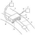
次に、図9を用いて、図8に示す超音波探傷装置で用いられる遠隔駆動装置50の概要を説明する。 Next, the outline of the
図9に示すように、遠隔駆動装置50には、ケーブル54を介して遠隔駆動装置50を制御する制御盤(制御部)60が接続されている。このような遠隔駆動装置50は、駆動車輪51と、駆動車輪用モーター55と、位置計測車輪53と、位置計測センサー56と、水平方向に装置を遊泳させるプロペラ45と、当該プロペラ45を回転させるモーター58と、上下方向に装置を遊泳させるプロペラ57と、当該プロペラ57を回転させるモーター59と、傾斜測定センサー52と、を有している。なお、遠隔駆動装置50は、これらの部材の全てを有する必要はなく、これらの部材の一部だけを有していてもよい。 As shown in FIG. 9, the
図9において、上述した水平方向に装置を遊泳させるプロペラ45により、遠隔駆動装置50を被検査構造物5の壁面に吸着させ、駆動車輪51により水平方向または上下方向に駆動することができる。 In FIG. 9, the
また、図9において、傾斜測定センサー52が検出するデータを、制御盤60による駆動車輪51の制御にフィードバックすることにより、遠隔駆動装置50を常時水平に保つことができる。また、遠隔駆動装置50には、上下左右にリンク機構48を取り付けることができ、当該リンク機構48を介して超音波探傷試験用探触子1を設置することができる。 In FIG. 9, the data detected by the
なお、上記では、水平方向に延在する複数の溶接線46に対して同時に超音波探傷試験を実施する態様について説明したが、これに限ることなく、垂直方向に延在する複数の溶接線46に対して同時に超音波探傷試験を実施することもできる。 In addition, although the aspect which implements an ultrasonic flaw detection test simultaneously with respect to the
また、上記では、超音波探傷試験用探触子1を用いて説明したが、これに限ることなく、超音波探傷試験用探触子1の代わりに、目視点検用カメラ、渦電流試験用探触子または放射線透過試験用探触子などを用いてもよい。 Although the ultrasonic flaw
1 超音波探傷試験用探触子
3 フェーズドアレイ探触子
4 水距離一定保持治具
5 被検査構造物
5a 被検査構造物の表面
12 車輪
13 伸縮機構
17 探傷器
23 ケーブル
38 ホース
39 水供給ポンプ
40 プローブフォルダー
41 駆動用ベルト
43 チャンバー機構
44 駆動機構
45 プロペラ
46 溶接線
48 リンク機構
49 位置計測センサー
50 遠隔駆動装置
51 駆動車輪
52 傾斜測定センサー
53 位置計測用車輪
54 ケーブル
55 駆動車輪用モーター
56 位置計測センサー
57 プロペラ
58,59 モーター
60 制御盤(制御部)
d ひびの深さ
D1 被検査構造物の超音波探傷試験用探触子が存在する面に開口面を有するひび
D2 被検査構造物の超音波探傷試験用探触子が存在する面と逆の面に開口面を有するひび
D3 被検査構造物に内在するひび
L 路程
QL ずれ量
Qw ずれ量
Sa Aスコープ信号
Sb Bスコープ信号
US 超音波
USia,USib,USic 被検査構造物に入射する超音波
USra,USrb,USrc 被検査構造物内で屈折した超音波
W 水
Θs 被検査構造物の表面の傾斜角
Θia,Θib,Θic 入射角
Θra,Θrb,Θrc 屈折角DESCRIPTION OF
d Depth of crack D1 Crack having an opening on the surface where the probe for ultrasonic flaw detection test of the structure to be inspected D2 Surface having the probe for ultrasonic flaw detection test of the structure to be inspected Crack D3 having an opening surface on the opposite surface Crack3 L path length QL displacement amount Qw displacement amount Sa A scope signal Sb B scope signal US Ultrasound USia , USib , USic Ultrasonic waves incident on the structure to be inspected USra , USrb , USrc Ultrasonic wave refracted in the structure to be inspected W Water Θs Angle of inclination of the surface of the structure to be inspected Θia , Θib , Θic Incident angle Θra , Θrb , Θrc refraction angle
Claims (3)
Translated fromJapanese被検査構造物の表面上に配置された保持機構と、
保持機構により被検査構造物の表面に対して非接触状態で保持されるとともに、一次元状または二次元状に配置された複数の超音波探傷試験用探触子を有するフェーズドアレイ探触子と、
超音波探傷試験用探触子からの信号に基づいて検出された被検査構造物の表面形状と、超音波探傷試験用探触子から発信された超音波の発信方向とに基づいて、被検査構造物の表面に対する超音波の入射角を検出する探傷器と、
を備え、
超音波探傷試験用探触子の各々は、超音波を被検査構造物内に発信するとともに、被検査構造物の欠陥から反射された超音波を受信することを特徴とする超音波探傷装置。In an ultrasonic flaw detector for inspecting defects generated in a structure to be inspected placed in water,
A holding mechanism disposed on the surface of the structure to be inspected;
A phased array probe that is held in a non-contact state with respect to the surface of the structure to be inspected by a holding mechanism and has a plurality of ultrasonic flaw detection probes arranged in a one-dimensional or two-dimensional manner; ,
Inspected based on the surface shape of the inspected structure detected based on the signal from the ultrasonic flaw detection test probe and the transmission direction of the ultrasonic wave transmitted from the ultrasonic flaw detection test probe A flaw detector for detecting the incident angle of the ultrasonic wave to the surface of the structure;
With
Each of the ultrasonic flaw detection test probes transmits an ultrasonic wave into a structure to be inspected and receives an ultrasonic wave reflected from a defect in the structure to be inspected.
保持機構により被検査構造物の表面に対して非接触状態で保持されるとともに、一次元状または二次元状に配置された複数の超音波探傷試験用探触子を有するフェーズドアレイ探触子と、
フェーズドアレイ探触子を覆って配置され、内部に水が充填されたチャンバー機構と、
超音波探傷試験用探触子からの信号に基づいて検出された被検査構造物の表面形状と、超音波探傷試験用探触子から発信された超音波の発信方向とに基づいて、被検査構造物の表面に対する超音波の入射角を検出する探傷器と、
を備え、
超音波探傷試験用探触子の各々は、超音波を被検査構造物内に発信するとともに、被検査構造物の欠陥から反射された超音波を受信することを特徴とする超音波探傷装置。In an ultrasonic flaw detector for inspecting a defect generated in a structure to be inspected disposed in a gas, a holding mechanism disposed on the surface of the structure to be inspected;
A phased array probe that is held in a non-contact state with respect to the surface of the structure to be inspected by a holding mechanism and has a plurality of ultrasonic flaw detection probes arranged in a one-dimensional or two-dimensional manner; ,
A chamber mechanism placed over the phased array probe and filled with water;
Inspected based on the surface shape of the inspected structure detected based on the signal from the ultrasonic flaw detection test probe and the transmission direction of the ultrasonic wave transmitted from the ultrasonic flaw detection test probe A flaw detector for detecting the incident angle of the ultrasonic wave to the surface of the structure;
With
Each of the ultrasonic flaw detection test probes transmits an ultrasonic wave into a structure to be inspected and receives an ultrasonic wave reflected from a defect in the structure to be inspected.
Priority Applications (1)
| Application Number | Priority Date | Filing Date | Title |
|---|---|---|---|
| JP2007050266AJP5010944B2 (en) | 2007-02-28 | 2007-02-28 | Ultrasonic flaw detector |
Applications Claiming Priority (1)
| Application Number | Priority Date | Filing Date | Title |
|---|---|---|---|
| JP2007050266AJP5010944B2 (en) | 2007-02-28 | 2007-02-28 | Ultrasonic flaw detector |
Publications (2)
| Publication Number | Publication Date |
|---|---|
| JP2008215877A JP2008215877A (en) | 2008-09-18 |
| JP5010944B2true JP5010944B2 (en) | 2012-08-29 |
Family
ID=39836100
Family Applications (1)
| Application Number | Title | Priority Date | Filing Date |
|---|---|---|---|
| JP2007050266AActiveJP5010944B2 (en) | 2007-02-28 | 2007-02-28 | Ultrasonic flaw detector |
Country Status (1)
| Country | Link |
|---|---|
| JP (1) | JP5010944B2 (en) |
Families Citing this family (6)
| Publication number | Priority date | Publication date | Assignee | Title |
|---|---|---|---|---|
| JP5959677B2 (en)* | 2015-02-25 | 2016-08-02 | 株式会社東芝 | Ultrasonic flaw detection apparatus and ultrasonic flaw detection method |
| KR101635950B1 (en)* | 2015-05-13 | 2016-07-04 | 한국건설기술연구원 | Apparatus and Method for Non-contact Measurement of Concrete Strength Ultrasonic Waves |
| JP5890572B1 (en)* | 2015-09-18 | 2016-03-22 | 株式会社計測工業 | Underwater inspection apparatus and method |
| WO2019075347A1 (en)* | 2017-10-12 | 2019-04-18 | GE Oil & Gas, LLC | Ultrasonic testing inspection with coupling validation |
| CN111413410B (en)* | 2020-03-24 | 2023-05-16 | 武汉中科创新技术股份有限公司 | Wheel type probe detection method in ultrasonic phased array composite material detection |
| CN117214307B (en)* | 2023-11-09 | 2024-02-02 | 山西诚达工程质量检测有限公司 | Nondestructive inspection device for steel structure welding seam |
Family Cites Families (4)
| Publication number | Priority date | Publication date | Assignee | Title |
|---|---|---|---|---|
| JPH032852Y2 (en)* | 1986-10-16 | 1991-01-25 | ||
| JPH1082771A (en)* | 1996-09-05 | 1998-03-31 | Ishikawajima Harima Heavy Ind Co Ltd | Inspection device for container body |
| JP3680805B2 (en)* | 2002-03-18 | 2005-08-10 | Jfeスチール株式会社 | Probe holder |
| JP4360175B2 (en)* | 2003-10-24 | 2009-11-11 | 株式会社日立製作所 | Ultrasonic transmission / reception array sensor, ultrasonic flaw detector, and ultrasonic flaw detection method therefor |
- 2007
- 2007-02-28JPJP2007050266Apatent/JP5010944B2/enactiveActive
Also Published As
| Publication number | Publication date |
|---|---|
| JP2008215877A (en) | 2008-09-18 |
Similar Documents
| Publication | Publication Date | Title |
|---|---|---|
| JP4832550B2 (en) | Ultrasonic flaw detector | |
| US8215174B2 (en) | Inspection apparatus for tubular members | |
| CN104698088B (en) | Pressure pipeline TOFD detection methods and device based on ultrasonic phase array | |
| JP4839333B2 (en) | Ultrasonic inspection method and ultrasonic inspection apparatus | |
| KR100884524B1 (en) | Automotive ultrasonic flaw detector | |
| JP5662873B2 (en) | Ultrasonic flaw detection method | |
| KR100975330B1 (en) | Ultrasonic flaw detector system and its control method | |
| US20090314089A1 (en) | Ultrasonic inspection probe carrier system for performing non-destructive testing | |
| JP5010944B2 (en) | Ultrasonic flaw detector | |
| JP5931551B2 (en) | Ultrasonic flaw detector, ultrasonic sensor support device, and ultrasonic flaw detector method | |
| CN101672829A (en) | Method for measuring parameter of omega welding seam defect | |
| JP5840910B2 (en) | Ultrasonic flaw detection method | |
| KR20100045284A (en) | Calibration block (reference block) and calibration procedure for phased-array ultrasonic inspection | |
| KR101163554B1 (en) | Calibration block for phased-array ultrasonic inspection and verification | |
| CN204495776U (en) | Based on the pressure pipeline TOFD pick-up unit of ultrasonic phase array | |
| KR20180095049A (en) | Apparatus for controlling and measuring welding defects on a cylindrical wall and a method for implementing the same | |
| CN102841142A (en) | Weld joint detecting method based on ultrasonic detection device | |
| KR20100124238A (en) | Calibration (Contrast) Specimen and Calibration Procedure for Phased Array Ultrasonic Testing | |
| JP4357265B2 (en) | Ultrasonic flaw detector and ultrasonic flaw detector method | |
| JPH04231899A (en) | Inspecting apparatus for housing in reactor core | |
| JPH11326291A (en) | Apparatus and method for ultrasonic examination of narrow part of reactor | |
| RU177780U1 (en) | Device for automated ultrasonic testing of welded joints | |
| CN117129569A (en) | A quality detection method for ultrasonic transducers and casings | |
| CN112326798B (en) | Ultrasonic detection method for crane T-shaped weld joint region defects | |
| JP3571473B2 (en) | Angle beam ultrasonic inspection method and apparatus |
Legal Events
| Date | Code | Title | Description |
|---|---|---|---|
| A621 | Written request for application examination | Free format text:JAPANESE INTERMEDIATE CODE: A621 Effective date:20090326 | |
| A977 | Report on retrieval | Free format text:JAPANESE INTERMEDIATE CODE: A971007 Effective date:20110531 | |
| A131 | Notification of reasons for refusal | Free format text:JAPANESE INTERMEDIATE CODE: A131 Effective date:20110603 | |
| A521 | Written amendment | Free format text:JAPANESE INTERMEDIATE CODE: A523 Effective date:20110726 | |
| TRDD | Decision of grant or rejection written | ||
| A01 | Written decision to grant a patent or to grant a registration (utility model) | Free format text:JAPANESE INTERMEDIATE CODE: A01 Effective date:20120511 | |
| A01 | Written decision to grant a patent or to grant a registration (utility model) | Free format text:JAPANESE INTERMEDIATE CODE: A01 | |
| A61 | First payment of annual fees (during grant procedure) | Free format text:JAPANESE INTERMEDIATE CODE: A61 Effective date:20120604 | |
| R151 | Written notification of patent or utility model registration | Ref document number:5010944 Country of ref document:JP Free format text:JAPANESE INTERMEDIATE CODE: R151 | |
| FPAY | Renewal fee payment (event date is renewal date of database) | Free format text:PAYMENT UNTIL: 20150608 Year of fee payment:3 |