Movatterモバイル変換


[0]ホーム

URL:


JP5009684B2 - Sample analyzer - Google Patents

Sample analyzer
Download PDF

Info

Publication number
JP5009684B2
JP5009684B2JP2007137044AJP2007137044AJP5009684B2JP 5009684 B2JP5009684 B2JP 5009684B2JP 2007137044 AJP2007137044 AJP 2007137044AJP 2007137044 AJP2007137044 AJP 2007137044AJP 5009684 B2JP5009684 B2JP 5009684B2
Authority
JP
Japan
Prior art keywords
reagent
unit
sample
arrangement
lid
Prior art date
Legal status (The legal status is an assumption and is not a legal conclusion. Google has not performed a legal analysis and makes no representation as to the accuracy of the status listed.)
Active
Application number
JP2007137044A
Other languages
Japanese (ja)
Other versions
JP2008032688A (en
Inventor
信宏 喜多川
周平 金子
教蔵 藤田
Current Assignee (The listed assignees may be inaccurate. Google has not performed a legal analysis and makes no representation or warranty as to the accuracy of the list.)
Sysmex Corp
Original Assignee
Sysmex Corp
Priority date (The priority date is an assumption and is not a legal conclusion. Google has not performed a legal analysis and makes no representation as to the accuracy of the date listed.)
Filing date
Publication date
Application filed by Sysmex CorpfiledCriticalSysmex Corp
Priority to JP2007137044ApriorityCriticalpatent/JP5009684B2/en
Priority to EP17185276.7Aprioritypatent/EP3267203B1/en
Priority to ES17185276Tprioritypatent/ES2714182T3/en
Priority to EP07012708.9Aprioritypatent/EP1873530B1/en
Priority to ES07012708.9Tprioritypatent/ES2645528T3/en
Priority to US11/824,228prioritypatent/US7931863B2/en
Publication of JP2008032688ApublicationCriticalpatent/JP2008032688A/en
Application grantedgrantedCritical
Publication of JP5009684B2publicationCriticalpatent/JP5009684B2/en
Activelegal-statusCriticalCurrent
Anticipated expirationlegal-statusCritical

Links

Images

Classifications

Landscapes

Description

Translated fromJapanese

この発明は、試料分析装置に関し、特に、試薬が収容された試薬容器を配置可能な配置部を備えた試料分析装置に関する。  The present invention relates to a sample analyzer, and more particularly, to a sample analyzer provided with an arrangement portion in which a reagent container containing a reagent can be arranged.

従来、試薬が収容された試薬容器を配置可能な配置部が移動可能に構成された試料分析装置が知られている(たとえば、特許文献1参照)。  2. Description of the Related Art Conventionally, there has been known a sample analyzer in which an arrangement unit capable of arranging a reagent container containing a reagent is movable (see, for example, Patent Document 1).

上記特許文献1に記載の試料分析装置は、試薬が入っている複数の試薬ボトルを収納する収納手段と、収納手段に配置されている試薬ボトル内の残量を計測する計測手段と、計測手段の計測結果に基づいて交換対象の試薬ボトルを特定する特定手段と、特定手段によって測定された試薬ボトルを所定の位置に移動させる移動手段とを備えている。  The sample analysis apparatus described inPatent Document 1 includes a storage unit that stores a plurality of reagent bottles containing reagents, a measurement unit that measures the remaining amount in the reagent bottle disposed in the storage unit, and a measurement unit. Specific means for specifying the reagent bottle to be replaced based on the measurement result, and moving means for moving the reagent bottle measured by the specifying means to a predetermined position.

特開2000−321283号公報JP 2000-321283 A

多数の試薬を用いる試料分析装置では、予備の試薬容器を配置することができるので、1つの試薬容器に収容された試薬の残量が不足しているとしても、その試薬を交換する必要がない場合が多い。つまり、試薬の不足状態が必ずしも交換対象であることを意味しない。しかしながら、上記特許文献1に記載の試料分析装置では、試薬容器中の試薬が不足状態にあることを検出して自動的に試薬が不足状態にある試薬容器を所定の位置(取出位置)に移動させるので、使用者が交換したい試薬が収容された試薬容器を取出位置に移動させることができないという問題点がある。  In a sample analyzer using a large number of reagents, a spare reagent container can be arranged, so even if the remaining amount of the reagent stored in one reagent container is insufficient, it is not necessary to replace the reagent. There are many cases. In other words, it does not necessarily mean that a reagent shortage is a replacement target. However, in the sample analyzer described inPatent Document 1, it is detected that the reagent in the reagent container is in a shortage state, and the reagent container in the reagent shortage state is automatically moved to a predetermined position (extraction position). Therefore, there is a problem that the reagent container in which the reagent that the user wants to replace cannot be moved to the removal position.

この発明は、上記のような課題を解決するためになされたものであり、この発明の1つの目的は、使用者が試薬を交換する場合に交換対象の試薬が配置された配置領域を容易に認識することが可能であり、試薬の交換、追加を容易に行うことが可能な試料分析装置を提供することである。
またこの発明の別の目的は、使用者が試薬を取り出す場合には取り出し対象の試薬が配置された配置領域を容易に認識することが可能であり、試薬の取り出しを容易に行うことが可能な試料分析装置を提供することである。
The present invention has been made to solve the above-described problems, and one object of the present invention isto easily provide an arrangement region in which a reagent to be replaced is arranged when a user replaces the reagent. It is an object of the present invention to provide a sample analyzercapable of recognizing and easily exchanging and adding reagents .
Another object of the present invention is that when the user takes out the reagent, the arrangement area where the reagent to be taken out is arranged can be easily recognized, and the reagent can be taken out easily. A sample analyzer is provided.

課題を解決するための手段および発明の効果Means for Solving the Problems and Effects of the Invention

この発明の第1の局面による試料分析装置は、試料を分析する試料分析装置であって、試薬が収容された試薬容器を配置するための複数の配置領域を有し、複数の配置領域を移動可能な配置部と、試料と試薬とが混合されて調製された測定試料を分析する分析部と、配置部の配置領域に配置された試薬容器の配置状態を表示し、試薬の配置領域を指定可能に表示する表示部と、表示部に表示された複数の配置領域の中から配置領域を指定するための入力部と、入力部により指定された配置領域に対応する配置部上の配置領域を、試薬容器の交換または追加が可能な交換追加位置へ移動させるように配置部を制御することが可能な制御部とを備える。A sample analyzer according to a first aspect of the present invention is a sample analyzer for analyzing a sample, and has a plurality of arrangement regions for arranging reagent containers containing reagents, and moves between the plurality of arrangement regions.Displays the possible placement part, the analysis part that analyzes the measurement sample prepared by mixing the sample and the reagent, andthe placement state of the reagent container placed in the placement area of the placement part, and specifies the reagent placement area A display section that can be displayed, an input section for designating a layout area from a plurality of layout areas displayed on the display section, and a layout areaon the layout section corresponding tothe layout areaspecified by the input sectionAnda control unitcapable of controlling the arrangement unit so asto move toa replacement addition position where the reagent container can be replaced or added .

この第1の局面による試料分析装置では、上記の構成によって、使用者が、交換しようとする試薬が収容された試薬容器を配置しようとする配置領域を指定することにより、指定した配置領域を、交換しようとする試薬が収容された試薬容器の交換が可能な交換追加位置に移動させることができる。これにより、使用者が交換したい試薬が収容された試薬容器を取出位置に移動させることができる。また、同様に、使用者が、追加しようとする試薬が収容された試薬容器を配置するための配置領域を指定することにより、指定した配置領域を、追加しようとする試薬が収容された試薬容器の追加が可能な交換追加位置に移動させることができる。また、使用者は、配置領域を表示部により確認しながら、容易に、試薬の交換または追加を行う配置領域を指定して、選択することができる。また、使用者は、試薬容器の配置状態を確認しながら、試薬の交換または追加を行う配置領域を指定して、選択することができる。In the sample analyzer according to the first aspect, with the above-describedconfiguration , the user designates an arrangement area in which a reagent container containing a reagent to be exchanged is to be arranged, thereby specifying the designated arrangement area, The reagent container in which the reagent to be exchanged is stored can be moved to an exchange addition position where the reagent container can be exchanged. Thereby, the reagent container in which the reagent which a user wants to replace | exchange can be moved to an extraction position. Similarly, the user designates an arrangement area for arranging the reagent container in which the reagent to be added is accommodated, so that the reagent container in which the reagent to be added is accommodated is designated. It is possible to move to a replacement addition position where addition of theIn addition, the user can easily designate and select an arrangement area for reagent replacement or addition while checking the arrangement area on the display unit. In addition, the user can designate and select an arrangement area where the reagent is exchanged or added while confirming the arrangement state of the reagent container.

上記第1の局面による試料分析装置において、好ましくは、入力部は、タッチパネル機能を有する表示部である。
The specimen processing device according to the first aspect, preferably, the input unitis adisplay unit having adata touch panelfunction.

上記第1の局面による試料分析装置において、好ましくは、表示部は、配置領域に配置された試薬容器の試薬が指定された場合、指定された試薬の属性情報を表示するように構成されている。このように構成すれば、使用者は、表示部に表示された試薬容器に収容された試薬を指定することにより、指定した試薬の属性情報を確認することができる。In thesample analyzer according to the first aspect , preferably, the display unit is configured to display the attribute information of the designated reagent when the reagent in the reagent container arranged in the arrangement region is designated. . If comprised in this way, the user can confirm the attribute information of the designated reagent by designating the reagent accommodated in the reagent container displayed on the display part.

上記第1の局面による試料分析装置において、好ましくは、試薬に関する情報を試薬容器から取得する試薬情報取得部をさらに備え、制御部は、試薬が交換または追加された場合、交換または追加された試薬の試薬情報を取得するように配置部および試薬情報取得部を制御するように構成されている。このように構成すれば、試薬を交換または追加した場合に、試薬情報取得部により、交換または追加した試薬の試薬情報を取得することができるので、使用者は、容易に、試薬を管理することができる。  The sample analyzer according to the first aspect preferably further includes a reagent information acquisition unit that acquires information about the reagent from the reagent container, and the control unit replaces or adds the reagent when the reagent is replaced or added. The arrangement unit and the reagent information acquisition unit are controlled to acquire the reagent information. With this configuration, when the reagent is replaced or added, the reagent information acquisition unit can acquire the reagent information of the replaced or added reagent, so that the user can easily manage the reagent. Can do.

この場合、好ましくは、配置部が、複数の試薬容器を保持するための複数の試薬ラックを配置可能であり、制御部は、試薬が交換または追加された場合、交換または追加された試薬が収容された試薬容器が保持されている試薬ラック中の試薬容器の試薬情報を取得するように配置部および試薬情報取得部を制御するように構成されている。このように構成すれば、交換または追加した試薬と同じ試薬ラックにおいて、交換または追加した試薬に加えて別途試薬を交換または追加した場合であっても、別途交換または追加した試薬の試薬情報を取得することができる。  In this case, preferably, the arrangement unit can arrange a plurality of reagent racks for holding a plurality of reagent containers, and when the reagent is exchanged or added, the control unit accommodates the exchanged or added reagent. The arrangement unit and the reagent information acquisition unit are configured to acquire the reagent information of the reagent container in the reagent rack in which the reagent container is held. With this configuration, even when another reagent is replaced or added in addition to the replaced or added reagent in the same reagent rack as the replaced or added reagent, the reagent information of the separately replaced or added reagent is acquired. can do.

上記第1の局面による試料分析装置において、好ましくは、配置部を覆う蓋部をさらに備え、蓋部は、指定された試薬が収容された試薬容器の交換追加位置において開閉可能に構成されている。このように構成すれば、蓋部の開閉により、容易に、交換追加に移動された試薬容器を取り出すことができるとともに、新たな試薬容器を配置することができる。  The sample analyzer according to the first aspect preferably further includes a lid that covers the arrangement portion, and the lid is configured to be openable and closable at the replacement addition position of the reagent container in which the designated reagent is accommodated. . If comprised in this way, the reagent container moved to replacement addition can be taken out easily by opening and closing of a cover part, and a new reagent container can be arrange | positioned.

この場合、好ましくは、蓋部をロックするためのロック部と、ロック部による蓋部のロックの状態を検知するロック状態検知部と、試薬に関する情報を試薬容器から取得する試薬情報取得部とをさらに備え、制御部は、試薬の交換または追加後に、ロック状態検知部によってロック状態が検知された場合に、配置部に配置された試薬容器から試薬情報を取得するように配置部および試薬情報取得部を制御するように構成されている。このように構成すれば、試薬の交換または追加後に試薬情報を取得するための操作を別途行うことなく、蓋部のロックにより自動的に試薬情報を取得することができる。  In this case, preferably, a lock unit for locking the lid unit, a lock state detection unit for detecting the lock state of the lid unit by the lock unit, and a reagent information acquisition unit for acquiring information about the reagent from the reagent container In addition, the control unit obtains the placement unit and the reagent information so as to obtain the reagent information from the reagent container placed in the placement unit when the lock state is detected by the lock state detection unit after the replacement or addition of the reagent. It is comprised so that a part may be controlled. If comprised in this way, reagent information can be automatically acquired by the lock | rock of a cover part, without performing operation for acquiring reagent information separately after replacement | exchange or addition of a reagent.

上記蓋部を備える構成において、好ましくは、蓋部をロックするためのロック部をさらに備え、制御部は、指定された配置領域が交換追加位置に移動された場合に、ロックされた蓋部のロックを解除するようにロック部を制御するように構成されている。このように構成すれば、指定された配置領域が交換追加位置に移動された場合に、ロックを解除する解除操作を行うことなく、蓋部を取り外すことができるので、試薬の交換または追加作業が煩雑化することを抑制することができる。  Preferably, the configuration including the lid portion further includes a lock portion for locking the lid portion, and the control unit is configured to move the locked lid portion when the designated arrangement area is moved to the replacement additional position. It is configured to control the lock unit to release the lock. According to this configuration, when the designated arrangement area is moved to the replacement addition position, the lid can be removed without performing a release operation to release the lock, so that reagent replacement or addition work can be performed. Complications can be suppressed.

上記第1の局面による試料分析装置において、好ましくは、配置部は、複数の試薬容器が環状に配置されるとともに、回転移動可能な第1配置部と、第1配置部に対して同心円状に設けられ、試薬容器を環状に配置可能であり、回転移動可能な第2配置部とを含む。このように構成すれば、第1配置部または第2配置部のいずれか一方に配置された試薬によって測定試料の分析を行っている場合に、第1配置部または第2配置部のいずれか他方に配置された試薬の交換または追加を行うことができる。  In the sample analyzer according to the first aspect described above, preferably, the arrangement section is concentrically arranged with respect to the first arrangement section and the first arrangement section, in which a plurality of reagent containers are arranged in an annular shape, and the first arrangement section is rotatable. And a second placement portion that can be placed in a ring shape and is rotatable. If comprised in this way, when analyzing the measurement sample with the reagent arrange | positioned in any one of a 1st arrangement | positioning part or a 2nd arrangement | positioning part, either one of a 1st arrangement | positioning part or a 2nd arrangement | positioning part Replacement or addition of reagents placed in the can be performed.

上記第1の局面による試料分析装置において、好ましくは、指定された配置領域が交換追加位置に移動されたことを通知する第1通知部をさらに備える。このように構成すれば、使用者は、第1通知部によって、容易に、指定された配置領域が交換追加位置に移動されたことを確認することができる。  The sample analyzer according to the first aspect preferably further includes a first notification unit that notifies that the designated arrangement area has been moved to the replacement addition position. If comprised in this way, the user can confirm easily that the designated arrangement | positioning area | region was moved to the replacement | exchange addition position by the 1st notification part.

上記指定された試薬が収容された試薬容器が取出位置に移動された場合に、蓋部のロックを解除する構成において、好ましくは、ロック部による蓋部のロックが制御部によって解除されたことを通知する第2通知部をさらに備える。このように構成すれば、使用者は、第2通知部によって、容易に、蓋部のロックが解除されたことを確認することができる。  In the configuration in which the lid is unlocked when the reagent container containing the designated reagent is moved to the removal position, it is preferable that the lid is locked by the control unit. A second notification unit for notifying is further provided. If comprised in this way, the user can confirm easily that the lock | rock of the cover part was cancelled | released by the 2nd notification part.

上記第1の局面による試料分析装置において、好ましくは、配置部が、複数の試薬容器を保持するための複数の試薬ラックを着脱可能であり、制御部は、配置領域として試薬ラックが指定された場合、試薬容器の交換または追加が可能な交換追加位置へ、指定された試薬ラックを移動させるように配置部を制御する。このように構成すれば、交換または追加を行う試薬ラックを指定して交換追加位置へ移動させることにより、容易に、指定した試薬ラックに対して試薬の交換または追加を行うことができる。  In the sample analyzer according to the first aspect described above, preferably, the arrangement unit is detachable with a plurality of reagent racks for holding a plurality of reagent containers, and the control unit designates the reagent rack as the arrangement region. In this case, the placement unit is controlled so that the designated reagent rack is moved to an exchange addition position where reagent containers can be exchanged or added. With this configuration, the reagent rack to be exchanged or added can be designated and moved to the exchange addition position, whereby the reagent can be easily exchanged or added to the designated reagent rack.

この発明の第2の局面による試料分析装置は、試料を分析する試料分析装置であって、試薬が収容された複数の試薬容器を配置可能であり、移動可能な配置部と、試料と試薬とが混合されて調製された測定試料を分析する分析部と、配置部に配置された複数の試薬容器の配置状態を表示し、配置部に配置された試薬容器に収容された試薬を指定可能に表示する表示部と、表示部に表示された複数の試薬の中から試薬を指定するための入力部と、入力部により指定された試薬が収容された配置部上の試薬容器を、取り出しが可能な取出位置に移動させるように配置部を制御することが可能な制御部とを備えている。A sample analyzer according to a second aspect of the present invention is a sample analyzer for analyzing a sample, in which a plurality of reagent containers containing a reagent can be arranged, a movable arrangement part, a sample and a reagent, The analysis unit that analyzes the measurement sample prepared by mixing andthe arrangement status of multiple reagent containers arranged in the arrangement unit can be displayed, and the reagent contained in the reagent container arranged in the arrangement unit can be specified The display unit to display, the input unit for specifying the reagent from the multiple reagents displayed on the display unit, andthe reagent containeron the placement unit containing the reagent specified bythe input unit can be taken out And a control unitcapable of controlling the placement unit so as to be moved to a proper extraction position.

この第2の局面による試料分析装置では、上記の構成によって、制御部による配置部の制御により、使用者が指定した試薬が収容された試薬容器を、取り出しが可能な取出位置に移動させることができる。これにより、使用者が交換したい試薬が収容された試薬容器を取出位置に移動させることができる。In the sample analyzer according to the second aspect, with the above-describedconfiguration , the reagent container storing the reagent designated by the user can be moved to a take-out position where it can be taken out by controlling the arrangement unit by the control unit. it can. Thereby, the reagent container in which the reagent which a user wants to replace | exchange can be moved to an extraction position.

以下、本発明を具体化した実施形態を図面に基づいて説明する。  DESCRIPTION OF THE PREFERRED EMBODIMENTS Embodiments embodying the present invention will be described below with reference to the drawings.

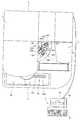
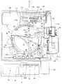
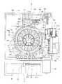
図1〜図5は、本発明の一実施形態による試料分析装置の全体構成を示す図である。図6は、本発明の一実施形態による試料分析装置の制御装置を説明するための図である。図7は、本発明の一実施形態による試料分析装置の表示部に表示される試薬配置画面を示す図である。図8〜図20は、本発明の一実施形態による試料分析装置の構造を説明するための図である。まず、図1〜図20を参照して、本発明の一実施形態による試料分析装置1の構造を説明する。  1 to 5 are diagrams showing an overall configuration of a sample analyzer according to an embodiment of the present invention. FIG. 6 is a diagram for explaining a control device of the sample analyzer according to the embodiment of the present invention. FIG. 7 is a diagram showing a reagent arrangement screen displayed on the display unit of the sample analyzer according to the embodiment of the present invention. FIGS. 8-20 is a figure for demonstrating the structure of the sample analyzer by one Embodiment of this invention. First, with reference to FIGS. 1-20, the structure of thesample analyzer 1 by one Embodiment of this invention is demonstrated.

本発明の一実施形態による試料分析装置1は、血液の凝固・線溶機能に関連する特定の物質の量や活性の度合いを光学的に測定して分析するための装置であり、検体としては血漿を用いる。本実施形態による試料分析装置1では、凝固時間法、合成基質法および免疫比濁法を用いて検体の光学的な測定(本測定)を行っている。本実施形態で用いる凝固時間法は、検体が凝固する過程を透過光の変化として検出する測定方法である。そして、測定項目としては、PT(プロトロンビン時間)、APTT(活性化部分トロンボプラスチン時間)やFbg(フィブリノーゲン量)などがある。また、合成基質法の測定項目としてはATIII等、免疫比濁法の測定項目としてはDダイマー、FDP等がある。  Asample analyzer 1 according to an embodiment of the present invention is an apparatus for optically measuring and analyzing the amount and the degree of activity of a specific substance related to blood coagulation / fibrinolysis function. Plasma is used. In thesample analyzer 1 according to the present embodiment, optical measurement (main measurement) of a specimen is performed using a coagulation time method, a synthetic substrate method, and an immunoturbidimetric method. The coagulation time method used in this embodiment is a measurement method that detects the process of coagulation of a specimen as a change in transmitted light. Measurement items include PT (prothrombin time), APTT (activated partial thromboplastin time), and Fbg (fibrinogen amount). In addition, measurement items of the synthetic substrate method include ATIII and the like, and measurement items of the immunoturbidimetric method include D dimer, FDP and the like.

そして、試料分析装置1は、図1および図2に示すように、測定機構部2と、測定機構部2の前面側に配置された検体搬送機構部3と、測定機構部2に電気的に接続された制御装置4とにより構成されている。また、測定機構部2には、測定を行う際の検体の容器となるキュベット200(図4参照)を投入するキュベット投入部5が設けられている。キュベット投入部5には、開閉可能な蓋5aと、キュベット投入部5の中を視認可能な窓5bとが設けられている。また、キュベット投入部5の前面側には、緊急停止ボタン1aと、測定開始ボタン1bとが設けられている。蓋5a(図1参照)は、後述するキュベット供給機構部170の第1ホッパ171a(図4参照)にキュベット200を投入するために設けられている。また、ユーザは、窓5bから第1ホッパ171a(図4参照)に貯留されているキュベット200の残量を視認することが可能である。緊急停止ボタン1a(図1参照)は、緊急の場合に測定を停止させる機能を有する。測定開始ボタン1b(図1参照)は、押すことにより、測定が開始されるように構成されている。これにより、ユーザは、キュベット200を投入した後、直ぐに測定を開始することが可能である。なお、制御装置4の操作によっても測定の開始および停止が可能である。  As shown in FIGS. 1 and 2, thesample analyzer 1 is electrically connected to themeasurement mechanism unit 2, the sampletransport mechanism unit 3 disposed on the front side of themeasurement mechanism unit 2, and themeasurement mechanism unit 2. It is comprised with thecontrol apparatus 4 connected. In addition, themeasurement mechanism unit 2 is provided with a cuvette loading unit 5 for loading a cuvette 200 (see FIG. 4) serving as a sample container when performing measurement. The cuvette loading unit 5 is provided with alid 5 a that can be opened and closed and awindow 5 b that can be viewed through the cuvette loading unit 5. Further, an emergency stop button 1a and ameasurement start button 1b are provided on the front side of the cuvette insertion unit 5. Thelid 5a (see FIG. 1) is provided to put thecuvette 200 into afirst hopper 171a (see FIG. 4) of thecuvette supply mechanism 170, which will be described later. Further, the user can visually recognize the remaining amount of thecuvette 200 stored in thefirst hopper 171a (see FIG. 4) from thewindow 5b. The emergency stop button 1a (see FIG. 1) has a function of stopping measurement in an emergency. Themeasurement start button 1b (see FIG. 1) is configured to start measurement when pressed. Thereby, the user can start measurement immediately after inserting thecuvette 200. The measurement can also be started and stopped by operating thecontrol device 4.

制御装置4は、パーソナルコンピュータ401(PC)などからなり、図1および図2に示すように、制御部4aと、表示部4bと、キーボード4cとを含んでいる。制御部4aは、測定機構部2および搬送機構部3の動作制御を行うとともに、測定機構部2で得られた検体の光学的な情報を分析するための機能を有している。この制御部4aは、CPU、ROM、RAMなどからなる。また、表示部4bは、検体中に存在する干渉物質(ヘモグロビン、乳び(脂質)およびビリルビン)に関する情報と、制御部4aで得られた分析結果とを表示するために設けられている。  Thecontrol device 4 includes a personal computer 401 (PC) or the like, and includes acontrol unit 4a, adisplay unit 4b, and akeyboard 4c, as shown in FIGS. Thecontrol unit 4a controls the operation of themeasurement mechanism unit 2 and thetransport mechanism unit 3 and has a function for analyzing optical information of the specimen obtained by themeasurement mechanism unit 2. Thecontrol unit 4a includes a CPU, a ROM, a RAM, and the like. Thedisplay unit 4b is provided to display information on interfering substances (hemoglobin, chyle (lipid) and bilirubin) present in the specimen and the analysis result obtained by thecontrol unit 4a.

次に、制御装置4の構成について詳細に説明する。制御部4aは、図6に示すように、CPU401aと、ROM401bと、RAM401cと、ハードディスク401dと、読出装置401eと、入出力インタフェース401fと、通信インタフェース401gと、画像出力インタフェース401hとから主として構成されている。CPU401a、ROM401b、RAM401c、ハードディスク401d、読出装置401e、入出力インタフェース401f、通信インタフェース401g、および画像出力インタフェース401hは、バス401iによって接続されている。  Next, the configuration of thecontrol device 4 will be described in detail. As shown in FIG. 6, thecontrol unit 4a mainly includes aCPU 401a, aROM 401b, aRAM 401c, ahard disk 401d, areading device 401e, an input /output interface 401f, acommunication interface 401g, and animage output interface 401h. ing. TheCPU 401a,ROM 401b,RAM 401c,hard disk 401d,reading device 401e, input /output interface 401f,communication interface 401g, andimage output interface 401h are connected by abus 401i.

CPU401aは、ROM401bに記憶されているコンピュータプログラムおよびRAM401cにロードされたコンピュータプログラムを実行することが可能である。そして、後述するようなアプリケーションプログラム404aをCPU401aが実行することにより、コンピュータ401が制御装置4として機能する。  TheCPU 401a can execute computer programs stored in theROM 401b and computer programs loaded in theRAM 401c. Thecomputer 401 functions as thecontrol device 4 when theCPU 401a executes anapplication program 404a as will be described later.

ROM401bは、マスクROM、PROM、EPROM、EEPROMなどによって構成されており、CPU401aに実行されるコンピュータプログラムおよびこれに用いるデータなどが記録されている。  TheROM 401b is configured by a mask ROM, PROM, EPROM, EEPROM, or the like, in which computer programs executed by theCPU 401a and data used for the same are recorded.

RAM401cは、SRAMまたはDRAMなどによって構成されている。RAM401cは、ROM401bおよびハードディスク401dに記録されているコンピュータプログラムの読み出しに用いられる。また、これらのコンピュータプログラムを実行するときに、CPU401aの作業領域として利用される。  TheRAM 401c is configured by SRAM, DRAM, or the like. TheRAM 401c is used to read out computer programs recorded in theROM 401b and thehard disk 401d. Further, when these computer programs are executed, they are used as a work area of theCPU 401a.

ハードディスク401dは、オペレーティングシステムおよびアプリケーションプログラムなど、CPU401aに実行させるための種々のコンピュータプログラムおよびそのコンピュータプログラムの実行に用いるデータがインストールされている。本実施形態に係る干渉物質の有無や濃度を算出するためのアプリケーションプログラム404aも、このハードディスク401dにインストールされている。  Thehard disc 401d is installed with various computer programs to be executed by theCPU 401a, such as an operating system and application programs, and data used for executing the computer programs. Anapplication program 404a for calculating the presence / absence and concentration of interfering substances according to the present embodiment is also installed in thehard disk 401d.

読出装置401eは、フレキシブルディスクドライブ、CD−ROMドライブ、またはDVD−ROMドライブなどによって構成されており、可搬型記録媒体404に記録されたコンピュータプログラムまたはデータを読み出すことができる。また、可搬型記録媒体404には、本実施形態に係るアプリケーションプログラム404aが格納されており、コンピュータ401がその可搬型記録媒体404からアプリケーションプログラム404aを読み出し、そのアプリケーションプログラム404aをハードディスク401dにインストールすることが可能である。  Thereading device 401e is configured by a flexible disk drive, a CD-ROM drive, a DVD-ROM drive, or the like, and can read a computer program or data recorded on theportable recording medium 404. Theportable recording medium 404 stores anapplication program 404a according to the present embodiment, and thecomputer 401 reads theapplication program 404a from theportable recording medium 404 and installs theapplication program 404a on thehard disk 401d. It is possible.

なお、上記アプリケーションプログラム404aは、可搬型記録媒体404によって提供されるのみならず、電気通信回線(有線、無線を問わない)によってコンピュータ401と通信可能に接続された外部の機器から上記電気通信回線を通じて提供することも可能である。たとえば、上記アプリケーションプログラム404aがインターネット上のサーバコンピュータのハードディスク内に格納されており、このサーバコンピュータにコンピュータ401がアクセスして、そのアプリケーションプログラム404aをダウンロードし、これをハードディスク401dにインストールすることも可能である。  Note that theapplication program 404a is not only provided by theportable recording medium 404, but also from an external device communicatively connected to thecomputer 401 by an electric communication line (whether wired or wireless). It is also possible to provide through. For example, theapplication program 404a is stored in a hard disk of a server computer on the Internet, and thecomputer 401 can access the server computer to download theapplication program 404a and install it on thehard disk 401d. It is.

また、ハードディスク401dには、たとえば、米マイクロソフト社が製造販売するWindows(登録商標)などのグラフィカルユーザインタフェース環境を提供するオペレーティングシステムがインストールされている。以下の説明においては、本実施形態に係るアプリケーションプログラム404aは上記オペレーティングシステム上で動作するものとしている。  In addition, an operating system that provides a graphical user interface environment such as Windows (registered trademark) manufactured and sold by US Microsoft Corporation is installed in thehard disc 401d. In the following description, it is assumed that theapplication program 404a according to the present embodiment operates on the operating system.

入出力インタフェース401fは、たとえば、USB、IEEE1394、RS−232Cなどのシリアルインタフェース、SCSI、IDE、IEEE1284などのパラレルインタフェース、およびD/A変換器、A/D変換器などからなるアナログインタフェースなどから構成されている。入出力インタフェース401fには、キーボード4cが接続されており、ユーザがそのキーボード4cを使用することにより、コンピュータ401にデータを入力することが可能である。  The input /output interface 401f includes, for example, a serial interface such as USB, IEEE 1394, and RS-232C, a parallel interface such as SCSI, IDE, and IEEE1284, and an analog interface including a D / A converter and an A / D converter. Has been. Akeyboard 4c is connected to the input /output interface 401f, and the user can input data to thecomputer 401 by using thekeyboard 4c.

通信インタフェース401gは、たとえば、Ethernet(登録商標)インタフェースである。コンピュータ401は、その通信インタフェース401gにより、所定の通信プロトコルを使用して測定機構部2との間でデータの送受信が可能である。  Thecommunication interface 401g is, for example, an Ethernet (registered trademark) interface. Thecomputer 401 can transmit and receive data to and from themeasurement mechanism unit 2 using a predetermined communication protocol through thecommunication interface 401g.

画像出力インタフェース401hは、LCDまたはCRTなどで構成された表示部4bに接続されており、CPU401aから与えられた画像データに応じた映像信号を表示部4bに出力するようになっている。表示部4bは、入力された映像信号にしたがって、画像(画面)を表示する。  Theimage output interface 401h is connected to adisplay unit 4b configured by an LCD or a CRT, and outputs a video signal corresponding to image data given from theCPU 401a to thedisplay unit 4b. Thedisplay unit 4b displays an image (screen) according to the input video signal.

ここで、本実施形態では、表示部4bは、図7に示すように、後述する試薬保存部6の試薬の配置を表示する試薬配置画面410を表示することが可能である。試薬配置画面410は、試薬配置表示領域420と、試薬情報表示領域430と、コマンド表示領域440とを有する。また、試薬配置画面410には、試料分析装置1の測定を開始するための測定開始ボタン411と、測定を停止するための測定停止ボタン412とが設けられている。なお、表示部4bは、タッチパネル機能を有し、試薬配置画面410に表示されるボタンなどをユーザが直接触れることによって選択または操作可能である。  Here, in the present embodiment, as shown in FIG. 7, thedisplay unit 4b can display areagent arrangement screen 410 that displays the arrangement of reagents in thereagent storage unit 6 described later. Thereagent arrangement screen 410 has a reagentarrangement display area 420, a reagentinformation display area 430, and acommand display area 440. Further, thereagent arrangement screen 410 is provided with ameasurement start button 411 for starting the measurement of thesample analyzer 1 and ameasurement stop button 412 for stopping the measurement. Thedisplay unit 4b has a touch panel function, and can be selected or operated by a user directly touching a button or the like displayed on thereagent arrangement screen 410.

試薬配置表示領域420は、後述する第1試薬テーブル11に配置されている試薬が表示される複数の第1試薬表示領域421と、後述する第2試薬テーブル12に配置されている試薬が表示される複数の第2試薬表示領域422とを含む。第1試薬表示領域421は、試薬の位置を表示する位置表示部421aと、試薬名を表示する試薬名表示部421bと、試薬の残量を表示する残量表示部421cとを含む。また、第2試薬表示領域422は、試薬の位置を表示する位置表示部422aと、試薬名を表示する試薬名表示部422bと、試薬の残量を表示する残量表示部422cとを含む。試薬名表示部421aおよび422aに表示される試薬の位置は、後述する第1試薬容器ラック310のバーコード311b、312bおよび第2試薬容器ラック320のバーコード321b〜326bをバーコードリーダ350により読み取ることによって表示される。また、試薬名表示部421bおよび422bに表示される試薬名は、試薬容器300のバーコード300aをバーコードリーダ350により読み取った値を元に、別途設けられたテーブルを参照して表示される。また、残量表示部421cおよび422cに表示される試薬の残量は、試薬が収容される容器の種類およびその試薬が吸引された回数などから算出した値を元に表示される。  The reagentarrangement display area 420 displays a plurality of firstreagent display areas 421 in which reagents arranged in the first reagent table 11 described later are displayed, and reagents arranged in the second reagent table 12 described later. And a plurality of secondreagent display areas 422. The firstreagent display area 421 includes aposition display unit 421a that displays the position of the reagent, a reagentname display unit 421b that displays the reagent name, and a remainingamount display unit 421c that displays the remaining amount of the reagent. The secondreagent display area 422 includes aposition display unit 422a that displays the position of the reagent, a reagentname display unit 422b that displays the reagent name, and a remainingamount display unit 422c that displays the remaining amount of the reagent. The positions of the reagents displayed on the reagentname display units 421a and 422a are read by abarcode reader 350 frombarcodes 311b and 312b of the firstreagent container rack 310 andbarcodes 321b to 326b of the secondreagent container rack 320 described later. Is displayed. The reagent names displayed in the reagentname display units 421b and 422b are displayed with reference to a separately provided table based on a value obtained by reading thebarcode 300a of thereagent container 300 with thebarcode reader 350. In addition, the remaining amount of the reagent displayed in the remainingamount display units 421c and 422c is displayed based on a value calculated from the type of container in which the reagent is stored, the number of times the reagent has been aspirated, and the like.

また、第1試薬表示領域421は、第1試薬テーブル11(図5参照)に配置される2つの試薬容器300を保持可能な5つの第1試薬容器ラック310(図5参照)に対応する領域毎に2つずつ分割されて表示される。また、第2試薬表示領域422は、第2試薬テーブル12(図5参照)に配置される6つの試薬容器300を保持可能な5つの第2試薬容器ラック320(図5参照)に対応する領域毎に6つずつ分割されて表示される。すなわち、試薬配置画面410では、どの試薬テーブル(第1試薬テーブル11または第2試薬テーブル12)の、どの試薬容器ラック(第1試薬容器ラック310または第2試薬容器ラック320)の、どの位置に試薬が配置されているかを確認することが可能である。  The firstreagent display area 421 corresponds to five first reagent container racks 310 (see FIG. 5) that can hold tworeagent containers 300 arranged in the first reagent table 11 (see FIG. 5). Each screen is divided into two. The secondreagent display area 422 is an area corresponding to five second reagent container racks 320 (see FIG. 5) that can hold sixreagent containers 300 arranged in the second reagent table 12 (see FIG. 5). Each of them is divided into six and displayed. That is, on thereagent arrangement screen 410, which reagent table (first reagent table 11 or second reagent table 12) and which reagent container rack (firstreagent container rack 310 or second reagent container rack 320) and which position are located. It is possible to confirm whether the reagent is arranged.

また、第1試薬容器ラック310または第2試薬容器ラック320が第1試薬テーブル11または第2試薬テーブル12に配置されていない場合には、第1試薬表示領域421または第2試薬表示領域422には、何も表示されない。また、第1試薬容器ラック310または第2試薬容器ラック320が第1試薬テーブル11または第2試薬テーブル12に配置されており、試薬容器ラックに保持される試薬容器300がない場合には、第1試薬表示領域421または第2試薬表示領域422には、位置表示部421aまたは位置表示部422aのみに表示がなされる。この点については、後で詳細に説明する。  Further, when the firstreagent container rack 310 or the secondreagent container rack 320 is not arranged on the first reagent table 11 or the second reagent table 12, the firstreagent display area 421 or the secondreagent display area 422 is displayed. Does not display anything. Further, when the firstreagent container rack 310 or the secondreagent container rack 320 is arranged on the first reagent table 11 or the second reagent table 12, and there is noreagent container 300 held in the reagent container rack, the firstreagent container rack 310 or the secondreagent container rack 320 is provided. The firstreagent display area 421 or the secondreagent display area 422 is displayed only on theposition display section 421a or theposition display section 422a. This point will be described in detail later.

また、試薬情報表示領域430には、第1試薬表示領域421または第2試薬表示領域422において指定された試薬の属性情報(ホルダ番号、試薬名、使用順、使用可能な残量(使用可能量)、残りテスト数、攪拌の有無、ロット番号、試薬容器の種類、試薬の有効期限、セット日およびセット時刻など)が表示される。この試薬の属性情報によって、ユーザは、試薬の交換時期を判断することが可能である。  In the reagentinformation display area 430, the attribute information of the reagent specified in the firstreagent display area 421 or the second reagent display area 422 (holder number, reagent name, order of use, usable remaining amount (usable amount) ), Remaining test number, presence / absence of agitation, lot number, reagent container type, reagent expiration date, set date and set time, and the like. Based on the reagent attribute information, the user can determine the replacement time of the reagent.

また、コマンド表示領域440には、試薬の交換または追加を指示するための交換・追加指示ボタン440aと、試薬情報の編集を行うための編集ボタン440bと、試薬ロットをマニュアルで入力するための試薬ロット設定ボタン440cとを含む。本実施形態では、試薬が指定された状態で、交換・追加指示ボタン440aが選択されることによって、指定された試薬が収容された試薬容器300を保持する第1試薬容器ラック310または第2試薬容器ラック320が、試料分析装置1から取出可能な取出位置に移動されるように構成されている。なお、試薬の追加が行われる場合には、試薬が配置されていない第1試薬表示領域421または第2試薬表示領域422が指定された状態で、交換・追加指示ボタン440aが選択される。これにより、試薬が収容されていない第1試薬容器ラック310または第2試薬容器ラック320が取出位置に移動される。  In thecommand display area 440, a replacement /addition instruction button 440a for instructing replacement or addition of a reagent, anediting button 440b for editing reagent information, and a reagent for manually inputting a reagent lot Alot setting button 440c. In the present embodiment, when the replacement /addition instruction button 440a is selected in a state where a reagent is designated, the firstreagent container rack 310 or the second reagent holding thereagent container 300 containing the designated reagent is selected. Thecontainer rack 320 is configured to be moved to an extraction position where it can be extracted from thesample analyzer 1. When a reagent is added, the replacement /addition instruction button 440a is selected in a state where the firstreagent display area 421 or the secondreagent display area 422 where no reagent is arranged is specified. As a result, the firstreagent container rack 310 or the secondreagent container rack 320 that does not contain the reagent is moved to the removal position.

検体搬送機構部3は、図1〜図3に示すように、測定機構部2に検体を供給するために、検体を収容した複数(本実施形態では、10本)の試験管250が載置されたラック251を測定機構部2の吸引位置2a(図3参照)に搬送する機能を有している。また、搬送機構部3は、未処理の検体を収容した試験管250が収納されたラック251をセットするためのラックセット領域3aと、処理済みの検体を収容した試験管250が収納されたラック251を収容するためのラック収容領域3bとを有している。  As shown in FIGS. 1 to 3, the sampletransport mechanism unit 3 is provided with a plurality of (in this embodiment, 10)test tubes 250 containing samples to supply the sample to themeasurement mechanism unit 2. Therack 251 is transported to thesuction position 2a (see FIG. 3) of themeasurement mechanism unit 2. In addition, thetransport mechanism unit 3 includes a rack setregion 3a for setting arack 251 in which atest tube 250 that stores an unprocessed sample is stored, and a rack in which atest tube 250 that stores a processed sample is stored. And a rackaccommodating area 3b for accommodating 251.

測定機構部2は、搬送機構部3から供給された検体に対して光学的な測定を行うことにより、供給された検体に関する光学的な情報を取得することが可能なように構成されている。本実施形態では、搬送機構部3のラック251に載置された試験管250から測定機構部2のキュベット200内に分注された検体に対して光学的な測定が行われる。また、測定機構部2は、図3に示すように、試薬を保存するための試薬保存部6と、試薬を交換または追加するための試薬交換部7とを含んでいる。  Themeasurement mechanism unit 2 is configured to be able to acquire optical information regarding the supplied sample by performing optical measurement on the sample supplied from thetransport mechanism unit 3. In the present embodiment, optical measurement is performed on the sample dispensed from thetest tube 250 placed on therack 251 of thetransport mechanism unit 3 into thecuvette 200 of themeasurement mechanism unit 2. Further, as shown in FIG. 3, themeasurement mechanism unit 2 includes areagent storage unit 6 for storing the reagent and areagent replacement unit 7 for replacing or adding the reagent.

測定機構部2は、図19に示すように、検体分注駆動部80aと、試薬分注駆動部130aと、第1駆動部502と、第2駆動部503と、第1検知部51と、第2検知部52と、試薬バーコードリーダ350と、検体バーコードリーダ3cと、第1光学的情報取得部90と、第2光学的情報取得部140と、搬送機構部3などに電気的に接続される制御部501とを有している。  As shown in FIG. 19, themeasurement mechanism unit 2 includes a sample dispensingdrive unit 80a, a reagent dispensingdrive unit 130a, afirst drive unit 502, asecond drive unit 503, afirst detection unit 51, Thesecond detection unit 52, thereagent barcode reader 350, thesample barcode reader 3c, the first opticalinformation acquisition unit 90, the second opticalinformation acquisition unit 140, and thetransport mechanism unit 3 are electrically connected. And acontrol unit 501 to be connected.

検体分注駆動部80aは、後述する検体分注アーム80(図3および図5参照)を回転上下させる機能を有するステッピングモータ部80bと、ステッピングモータ部80bを駆動させるための駆動回路(図示せず)と、検体を吸引および分注するためのポンプ(図示せず)とを備えている。  The sample dispensingdrive unit 80a includes a stepping motor unit 80b having a function of rotating and moving a sample dispensing arm 80 (see FIGS. 3 and 5), which will be described later, and a drive circuit (not shown) for driving the stepping motor unit 80b. And a pump (not shown) for aspirating and dispensing the sample.

試薬分注駆動部130aは、後述する試薬分注アーム130(図3および図5参照)を回転上下させる機能を有するステッピングモータ部130bと、ステッピングモータ部130bを駆動させるための駆動回路(図示せず)と、試薬を吸引および分注するためのポンプ(図示せず)とを備えている。  The reagentdispensing drive unit 130a includes a stepping motor unit 130b having a function of rotating and moving a reagent dispensing arm 130 (see FIGS. 3 and 5), which will be described later, and a drive circuit (not shown) for driving the stepping motor unit 130b. And a pump (not shown) for aspirating and dispensing the reagent.

第1駆動部502は、後述する第1試薬テーブル11(図5参照)を回転させる機能を有する第1ステッピングモータ(図示せず)と、第1ステッピングモータを駆動させるための駆動回路(図示せず)とを備えている。そして、第1試薬テーブル11は、制御部501から第1駆動部502に供給された駆動パルス信号のパルス数に応じた分だけ回転し、停止する。  Thefirst drive unit 502 includes a first stepping motor (not shown) having a function of rotating a first reagent table 11 (see FIG. 5) described later, and a drive circuit (not shown) for driving the first stepping motor. )). Then, the first reagent table 11 rotates by an amount corresponding to the number of pulses of the drive pulse signal supplied from thecontrol unit 501 to thefirst drive unit 502 and stops.

同様に、第2駆動部503は、後述する第1試薬テーブル12(図5参照)を回転させる機能を有する第2ステッピングモータ(図示せず)と、第2ステッピングモータを駆動させるための駆動回路(図示せず)とを備えている。そして、第2試薬テーブル12は、制御部501から第2駆動部503に供給された駆動パルス信号のパルス数に応じた分だけ回転し、停止する。  Similarly, thesecond drive unit 503 includes a second stepping motor (not shown) having a function of rotating a first reagent table 12 (see FIG. 5) described later, and a drive circuit for driving the second stepping motor. (Not shown). Then, the second reagent table 12 rotates by an amount corresponding to the number of pulses of the drive pulse signal supplied from thecontrol unit 501 to thesecond drive unit 503 and stops.

なお、制御部501は、供給した駆動パルス信号のパルス数をカウントすることにより、第1試薬テーブル11および第2試薬テーブル12の原点位置からの各試薬テーブル11、12の回転移動量を決定し、各試薬テーブル11、12の回転移動を制御することが可能である。  Thecontrol unit 501 counts the number of pulses of the supplied drive pulse signal to determine the rotational movement amount of each reagent table 11, 12 from the origin position of the first reagent table 11 and the second reagent table 12. The rotational movement of the reagent tables 11 and 12 can be controlled.

第1検知部51は、後述する第1蓋部30(図3参照)のロック状態を検知するとともに、ロックされたときにロック信号を制御部501に送信する機能を有している。  Thefirst detection unit 51 has a function of detecting a lock state of a first lid unit 30 (see FIG. 3) described later and transmitting a lock signal to thecontrol unit 501 when locked.

同様に、第2検知部52は、後述する第2蓋部40(図3参照)のロック状態を検知するとともに、ロックされたときにロック信号を制御部501に送信する機能を有している。  Similarly, the2nd detection part 52 has a function which transmits the lock signal to thecontrol part 501, while detecting the locked state of the 2nd cover part 40 (refer FIG. 3) mentioned later. .

試薬バーコードリーダ350は、第1試薬テーブル11および第2試薬テーブル12上の各バーコードを読み取る機能を有しており、後述する試薬保存部6の側面21の近傍に、試薬保存部6と所定の距離を隔てて設けられている(図3〜図5参照)。この試薬バーコードリーダ350は、制御部501との間でデータの送受信を行うことが可能であるとともに、試薬バーコードリーダ350をON/OFF制御するための駆動回路(図示せず)を有している。なお、試薬バーコードリーダ350の位置は常に固定されている。  Thereagent barcode reader 350 has a function of reading the barcodes on the first reagent table 11 and the second reagent table 12, and in the vicinity of theside surface 21 of thereagent storage unit 6 described later, They are provided at a predetermined distance (see FIGS. 3 to 5). Thereagent barcode reader 350 can transmit / receive data to / from thecontrol unit 501, and has a drive circuit (not shown) for ON / OFF control of thereagent barcode reader 350. ing. Note that the position of thereagent barcode reader 350 is always fixed.

検体バーコードリーダ3cは、搬送機構部3によって搬送されたラック251に載置された検体を収容した試験管250に貼付されたバーコードを読み取る機能を有しており、前述した測定機構部2の吸引位置2aの近傍に、搬送機構部3によって搬送されるラック251に対向するように設けられている(図3〜図5参照)。この検体バーコードリーダ3cは、制御部501との間でデータの送受信を行うことが可能であるとともに、検体バーコードリーダ3cをON/OFF制御するための駆動回路(図示せず)を有している。なお、検体バーコードリーダ3cの位置は常に固定されている。  Thesample barcode reader 3c has a function of reading a barcode attached to thetest tube 250 containing the sample placed on therack 251 conveyed by theconveyance mechanism unit 3, and themeasurement mechanism unit 2 described above. Is provided in the vicinity of thesuction position 2a so as to face therack 251 transported by the transport mechanism unit 3 (see FIGS. 3 to 5). Thesample barcode reader 3c can transmit / receive data to / from thecontrol unit 501, and has a drive circuit (not shown) for ON / OFF control of thesample barcode reader 3c. ing. The position of thespecimen barcode reader 3c is always fixed.

第1光学情報取得部90と第2光学情報取得部140(図3および図5参照)は、検体の光学的情報を取得するための機能を有しており、制御部501との間でデータの送受信を行うことが可能なように構成されている。第1光学情報取得部90と第2光学情報取得部140の詳細については後述する。  The first opticalinformation acquisition unit 90 and the second optical information acquisition unit 140 (see FIGS. 3 and 5) have a function for acquiring the optical information of the specimen, and data is transmitted between thecontrol unit 501 and the data. Are configured to be able to transmit and receive. Details of the first opticalinformation acquisition unit 90 and the second opticalinformation acquisition unit 140 will be described later.

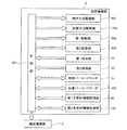
制御部501は、図20に示すように、CPU501aとROM501bと、RAM501cと、通信インタフェース501dとから主として構成されている。  As shown in FIG. 20, thecontrol unit 501 mainly includes aCPU 501a, aROM 501b, aRAM 501c, and acommunication interface 501d.

CPU501aは、ROM501bに記憶されているコンピュータプログラムおよびRAM501cに読み出されたコンピュータプログラムを実行することが可能である。ROM501bは、CPU501aに実行させるためのコンピュータプログラム及び当該コンピュータプログラムの実行に用いるデータ等を記憶している。RAM501cは、ROM501bに記憶しているコンピュータプログラムの読み出しに用いられる。また、これらのコンピュータプログラムを実行するときに、CPU501aの作業領域として利用される。  TheCPU 501a can execute a computer program stored in theROM 501b and a computer program read into theRAM 501c. TheROM 501b stores a computer program to be executed by theCPU 501a, data used for executing the computer program, and the like. TheRAM 501c is used for reading a computer program stored in theROM 501b. Further, when these computer programs are executed, they are used as a work area of theCPU 501a.

通信インタフェース501dは、制御装置4に接続されており、検体の光学的な情報を制御装置4に送信するとともに、制御装置4の制御部4aからの信号を受信するための機能を果たす。また、通信インタフェース501dは、搬送機構部3および測定機構部2の各部を駆動するためのCPU501aからの指令を送信するための機能を有する。  Thecommunication interface 501d is connected to thecontrol device 4 and transmits optical information of the specimen to thecontrol device 4 and functions to receive a signal from thecontrol unit 4a of thecontrol device 4. Thecommunication interface 501d has a function for transmitting a command from theCPU 501a for driving each part of thetransport mechanism unit 3 and themeasurement mechanism unit 2.

また、測定機構部2は、図3に示すように、試薬を保存するための試薬保存部6と、試薬を交換または追加するための試薬交換部7とを含んでいる。  Further, as shown in FIG. 3, themeasurement mechanism unit 2 includes areagent storage unit 6 for storing the reagent and areagent replacement unit 7 for replacing or adding the reagent.

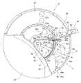
試薬保存部6は、キュベット200内の検体に添加される試薬を収容した試薬容器300を、低温(約10℃)で冷蔵保存するとともに、回転方向に搬送するために設けられている。試薬を低温で保存することにより、試薬が変質することが抑制される。また、試薬保存部6は、図3〜図5に示すように、試薬の保持および回転搬送を行う試薬搬送部10(図4および図5参照)と、試薬搬送部10の周囲および上方を覆うように設けられた外壁部20(図3参照)とを含んでいる。また、試薬が保持される試薬搬送部10は、外壁部20と、後述する試薬交換部7の第1蓋部30および第2蓋部40とにより形成される冷蔵領域に配置される。  Thereagent storage unit 6 is provided to refrigerate and store thereagent container 300 containing the reagent added to the specimen in thecuvette 200 at a low temperature (about 10 ° C.) and to transport it in the rotation direction. By storing the reagent at a low temperature, the reagent is prevented from being altered. As shown in FIGS. 3 to 5, thereagent storage unit 6 covers the reagent transport unit 10 (see FIGS. 4 and 5) that holds and rotates and transports the reagent, and thereagent transport unit 10. The outer wall part 20 (refer FIG. 3) provided in this way is included. In addition, thereagent transport unit 10 that holds the reagent is disposed in a refrigerated region formed by theouter wall 20 and afirst lid 30 and asecond lid 40 of thereagent replacement unit 7 described later.

この試薬搬送部10は、図5に示すように、円形状の第1試薬テーブル11と、円形状の第1試薬テーブル11の外側に、第1試薬テーブル11に対して同心円状に配置された円環形状の第2試薬テーブル12とを含む。また、第1試薬テーブル11および第2試薬テーブル12は、それぞれ、試薬容器300を保持する第1試薬容器ラック310および第2試薬容器ラック320が着脱可能に配置されるように構成されている。また、外壁部20は、側面21(図4参照)と、側面21に固定されている上面22(図3参照)と、取り外し可能な蓋部23(図3参照)とにより構成されている。また、試薬保存部6の側面21(図4参照)の近傍には、試薬保存部6と所定の距離を隔ててバーコードリーダ350が設けられている。  As shown in FIG. 5, thereagent transport unit 10 is arranged concentrically with the first reagent table 11 on the outer side of the circular first reagent table 11 and the circular first reagent table 11. And an annular second reagent table 12. The first reagent table 11 and the second reagent table 12 are configured such that a firstreagent container rack 310 and a secondreagent container rack 320 that hold thereagent containers 300 are detachably arranged, respectively. Moreover, theouter wall part 20 is comprised by the side surface 21 (refer FIG. 4), the upper surface 22 (refer FIG. 3) fixed to theside surface 21, and the removable cover part 23 (refer FIG. 3). Further, abarcode reader 350 is provided in the vicinity of the side surface 21 (see FIG. 4) of thereagent storage unit 6 with a predetermined distance from thereagent storage unit 6.

第1試薬テーブル11および第2試薬テーブル12は、それぞれ、時計回り方向および反時計回り方向の両方に回転可能で、かつ、各々のテーブルが互いに独立して回転可能なように構成されている。これにより、試薬が収容された試薬容器300を保持する第1試薬容器ラック310および第2試薬容器ラック320は、それぞれ、第1試薬テーブル11および第2試薬テーブル12によって回転方向に搬送される。また、試薬容器300を回転方向に搬送することによって、後述する試薬分注アーム130が試薬を分注する際に、分注対象の試薬を試薬分注アーム130の近傍に配置させることが可能である。  The first reagent table 11 and the second reagent table 12 are configured to be able to rotate both in the clockwise direction and in the counterclockwise direction, and to be able to rotate independently of each other. As a result, the firstreagent container rack 310 and the secondreagent container rack 320 that hold thereagent container 300 containing the reagent are conveyed in the rotation direction by the first reagent table 11 and the second reagent table 12, respectively. Further, by transporting thereagent container 300 in the rotation direction, it is possible to arrange the reagent to be dispensed in the vicinity of thereagent dispensing arm 130 when thereagent dispensing arm 130 described later dispenses the reagent. is there.

また、外壁部20の側面21には、断熱材(図示せず)が取り付けられており、試薬保存部6(冷蔵領域)内の冷気を逃がさないように構成されている。また、図4に示すように、外壁部20の側面21のバーコードリーダ350と対向する位置には、開閉可能なシャッタ21aが設けられている。このシャッタ21aは、バーコードリーダ350によって試薬容器300、第1試薬容器ラック310および第2試薬容器ラック320のバーコードを読み取る時にのみ開くように構成されている。これにより、試薬保存部6(冷蔵領域)内の冷気が外部に逃げることが抑制される。  Further, a heat insulating material (not shown) is attached to theside surface 21 of theouter wall portion 20 so that the cold air in the reagent storage portion 6 (refrigerated region) is not released. As shown in FIG. 4, an openable /closable shutter 21 a is provided at a position facing thebarcode reader 350 on theside surface 21 of theouter wall portion 20. Theshutter 21a is configured to be opened only when the barcode of thereagent container 300, the firstreagent container rack 310, and the secondreagent container rack 320 is read by thebarcode reader 350. Thereby, it is suppressed that the cold in the reagent storage part 6 (refrigeration area | region) escapes outside.

また、図3に示すように、外壁部20の上面22は、3つの穴部22a、22bおよび22cを含む。この3つの穴部22a、22bおよび22cを介して、試薬分注アーム130により試薬保存部6に保存されている試薬の吸引が行われる。なお、穴部22aは、第1試薬容器ラック310に保持されている試薬容器300の上方に位置する。この穴部22aを介して、第1試薬容器ラック310に保持されている試薬容器300から試薬の吸引が行われる。また、穴部22bおよび22cは、それぞれ、第2試薬容器ラック320の後列および前列に保持されている試薬容器300の上方に位置する。この穴部22bおよび22cを介して、第2試薬容器ラック320の後列および前列に保持されている試薬容器300から試薬の吸引が行われる。  As shown in FIG. 3, theupper surface 22 of theouter wall portion 20 includes threeholes 22a, 22b and 22c. The reagent stored in thereagent storage unit 6 is aspirated by thereagent dispensing arm 130 through the threeholes 22a, 22b and 22c. Thehole 22a is located above thereagent container 300 held in the firstreagent container rack 310. The reagent is aspirated from thereagent container 300 held in the firstreagent container rack 310 through thehole 22a. Theholes 22b and 22c are located above thereagent containers 300 held in the rear row and the front row of the secondreagent container rack 320, respectively. The reagent is aspirated from thereagent containers 300 held in the rear row and the front row of the secondreagent container rack 320 through theholes 22b and 22c.

また、蓋部23が後述する第1蓋部30および第2蓋部40とともに取り外されることによって、試薬保存部6(冷蔵領域)に半円形状の開口が形成される。この開口を介して、試料分析装置1において測定を開始する際に、試薬保存部6に第1試薬容器ラック310および第2試薬容器ラック320が配置される。  Further, when thelid portion 23 is removed together with thefirst lid portion 30 and thesecond lid portion 40 which will be described later, a semicircular opening is formed in the reagent storage portion 6 (refrigerated region). When the measurement is started in thesample analyzer 1 through the opening, the firstreagent container rack 310 and the secondreagent container rack 320 are arranged in thereagent storage unit 6.

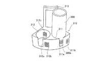
また、図5に示すように、第1試薬容器ラック310は、第1試薬テーブル11に5つ配置可能である。この5つの第1試薬容器ラック310に、試薬容器300が円環状に配置される。第1試薬容器ラック310は、図15および図17に示すように、試薬容器300を保持するための2つの保持部311および312と、保持部311および312の前面側にそれぞれ設けられた切欠部311aおよび312aと、上方に突出するように設けられた1つの把持部313とを含む。また、図17に示すように、保持部311および312は、平面的に見て円形状に形成されており、円筒形状の試薬容器300が差し込まれることにより試薬容器300を保持可能である。また、アダプタ(図示せず)を保持部311または312に取り付けることにより、上記保持部311または312の内径よりも小さい外径を有する試薬容器300を保持部311または312に保持させることが可能である。また、第1試薬容器ラック310は、保持部311および312の内径の組み合わせが異なるように形成された2種類のラックを含む。ユーザは、適宜ラックの種類を変えることによって、様々な大きさの試薬容器300に対応可能である。また、保持部311および312の外側面の前面側には、それぞれ、バーコード311bおよび312bが設けられており、保持部311および312の内側面には、それぞれ、バーコード311cおよび312cが設けられている。  Further, as shown in FIG. 5, five firstreagent container racks 310 can be arranged on the first reagent table 11. Thereagent containers 300 are annularly arranged in the five first reagent container racks 310. As shown in FIGS. 15 and 17, the firstreagent container rack 310 includes two holdingparts 311 and 312 for holding thereagent container 300, and a notch provided on the front side of the holdingparts 311 and 312. 311a and 312a and onegrip part 313 provided so as to protrude upward. As shown in FIG. 17, the holdingportions 311 and 312 are formed in a circular shape when seen in a plan view, and can hold thereagent container 300 by inserting thecylindrical reagent container 300. Further, by attaching an adapter (not shown) to the holdingunit 311 or 312, thereagent container 300 having an outer diameter smaller than the inner diameter of the holdingunit 311 or 312 can be held by the holdingunit 311 or 312. is there. The firstreagent container rack 310 includes two types of racks formed so that combinations of inner diameters of the holdingportions 311 and 312 are different. The user can cope withreagent containers 300 of various sizes by appropriately changing the type of rack. Further, barcodes 311b and 312b are provided on the front side of the outer surface of the holdingportions 311 and 312 respectively, and barcodes 311c and 312c are provided on the inner side surfaces of the holdingportions 311 and 312 respectively. ing.

2つの保持部311および312は、検体から測定用試料を調製する際に添加される種々の試薬を収容した複数の試薬容器300を1つずつ保持することが可能である。すなわち、第1試薬テーブル11には、10個(2×5=10)の試薬容器300が配置可能である。また、切欠部311aおよび312aは、それぞれ、バーコード311cおよび312cをバーコードリーダ350(図5参照)によって読み取るために設けられている。また、把持部313は、第1試薬容器ラック310を試薬保存部6から取り出す時に把持される。  The two holdingunits 311 and 312 can hold a plurality ofreagent containers 300 each containing various reagents added when preparing a measurement sample from a specimen. That is, ten (2 × 5 = 10)reagent containers 300 can be arranged in the first reagent table 11. Thenotches 311a and 312a are provided for reading thebarcodes 311c and 312c with the barcode reader 350 (see FIG. 5), respectively. In addition, thegrip portion 313 is gripped when the firstreagent container rack 310 is taken out from thereagent storage portion 6.

バーコード311bおよび312bには、それぞれ、保持部311および312の位置を識別するための位置情報が含まれている。また、バーコード311cおよび312cには、保持部311および312に保持される試薬容器300は存在しないことを示す情報(試薬容器無し情報)が含まれている。また、試薬容器300のバーコード300aには、試薬容器300に収容されている試薬の属性情報(ホルダ番号、試薬名、試薬容器の種類、ロット番号、試薬の有効期限などの情報)を特定するための情報が含まれている。すなわち、ホルダ番号は、バーコードリーダ350により読み取られた試薬容器300のバーコード300aを元に特定される。また、試薬名、試薬容器の種類、ロット番号、試薬の有効期限などは、バーコードリーダ350により読み取られた試薬容器300のバーコード300aを元に、別途設けられたテーブルを参照して特定される。  Thebar codes 311b and 312b include position information for identifying the positions of the holdingunits 311 and 312 respectively. Thebarcodes 311c and 312c include information (reagent absence information) indicating that thereagent container 300 held in the holdingunits 311 and 312 does not exist. Thebarcode 300a of thereagent container 300 identifies attribute information (information such as a holder number, a reagent name, a reagent container type, a lot number, and a reagent expiration date) stored in thereagent container 300. Contains information for. That is, the holder number is specified based on thebarcode 300 a of thereagent container 300 read by thebarcode reader 350. The reagent name, reagent container type, lot number, reagent expiration date, and the like are specified with reference to a separately provided table based on thebarcode 300a of thereagent container 300 read by thebarcode reader 350. The

なお、試薬容器300が保持部311に保持されている場合には、バーコード311cは読み取られず、試薬容器300のバーコード300aが読み取られる。すなわち、バーコードリーダ350によってバーコード311bを読み取った後にバーコード300aを読み取った場合は、制御部4aは、バーコード300aによる試薬情報を有する試薬が保持部311に保持されていると認識する。また、バーコードリーダ350によってバーコード311bを読み取った後にバーコード311cを読み取った場合は、制御部4aは、保持部311に保持されている試薬容器300は存在しないと認識する。また、バーコードリーダ350によってバーコード311bを読み取った後にバーコード300aまたはバーコード311cのいずれも読み取らなかった場合(試薬容器300が横を向いている場合など)には、制御部4aは、読み取りエラーを認識するとともに、表示部4bにおいて、読み取りが失敗したことが表示される。  When thereagent container 300 is held by the holdingunit 311, thebarcode 311 c is not read and thebarcode 300 a of thereagent container 300 is read. That is, when thebarcode 300a is read after thebarcode 311b is read by thebarcode reader 350, thecontrol unit 4a recognizes that the reagent having the reagent information by thebarcode 300a is held in the holdingunit 311. Further, when thebarcode 311c is read after thebarcode 311b is read by thebarcode reader 350, thecontrol unit 4a recognizes that thereagent container 300 held in the holdingunit 311 does not exist. Further, when neither thebarcode 300a nor thebarcode 311c is read after thebarcode 311b is read by the barcode reader 350 (for example, when thereagent container 300 faces sideways), thecontrol unit 4a reads thebarcode 311b. While recognizing the error, thedisplay unit 4b displays that reading has failed.

また、第2試薬容器ラック320は、図5に示すように、第2試薬テーブル12に5つ配置可能である。この5つの試薬容器ラック320に、試薬容器300が円環状に配置される。また、互いに隣接する第2試薬容器ラック320の5箇所の隙間のうち、1個所は、他の4箇所の隙間の間隔よりも大きい間隔を有する。この大きい間隔を有する隙間12aを介して、試薬保存部6の外部に位置するバーコードリーダ350により、第2試薬テーブル12の内側に位置する第1試薬テーブル11に配置される第1試薬容器ラック310のバーコード311bおよび312bと、第1試薬容器ラック310に保持される試薬容器300のバーコード300aとが読み取られる。また、第2試薬容器ラック320は、図16および図18に示すように、試薬容器300を保持するための6つの保持部321〜326と、保持部321〜326の前面側にそれぞれ設けられた切欠部321a〜326aと、上方に突出するように設けられた1つの把持部327とを含む。また、第2試薬容器ラック320の保持部321〜326は、第1試薬容器ラック310と同様に、平面的に見て円形状に形成されており、円筒形状の試薬容器300が差し込まれることにより試薬容器300を保持可能である。この第2試薬容器ラック320は、保持部321〜326の内径の組み合わせがそれぞれ異なるように形成された3種類のラックを含む。また、第2試薬容器ラック320には、第1試薬容器ラック310に配置された試薬と同じ試薬を配置することが可能に構成されている。  Further, five secondreagent container racks 320 can be arranged on the second reagent table 12 as shown in FIG. In these five reagent container racks 320, thereagent containers 300 are arranged in an annular shape. In addition, one of the five gaps of the secondreagent container rack 320 adjacent to each other has an interval larger than the interval between the other four gaps. The first reagent container rack arranged on the first reagent table 11 located inside the second reagent table 12 by thebarcode reader 350 located outside thereagent storage unit 6 through thegap 12a having a large interval. Thebarcodes 311b and 312b of 310 and thebarcode 300a of thereagent container 300 held in the firstreagent container rack 310 are read. Further, as shown in FIGS. 16 and 18, the secondreagent container rack 320 is provided on each of the six holdingparts 321 to 326 for holding thereagent container 300 and the front side of the holdingparts 321 to 326. It includesnotches 321a to 326a and onegrip 327 provided so as to protrude upward. Further, the holdingportions 321 to 326 of the secondreagent container rack 320 are formed in a circular shape when seen in a plan view, like the firstreagent container rack 310, and thecylindrical reagent container 300 is inserted. Thereagent container 300 can be held. The secondreagent container rack 320 includes three types of racks formed so that the combinations of the inner diameters of the holdingportions 321 to 326 are different from each other. Further, the secondreagent container rack 320 is configured such that the same reagent as the reagent arranged in the firstreagent container rack 310 can be arranged.

また、前列側の切欠部321aの両側には、バーコード321bと322bとが設けられている。また、同様に、切欠部323aの両側および切欠部325aの両側には、それぞれ、バーコード323bおよび324b、および、バーコード325bおよび326bが設けられている。また、保持部321〜326の内側面には、それぞれ、バーコード321c〜326cが設けられている。  Further, barcodes 321b and 322b are provided on both sides of thenotch portion 321a on the front row side. Similarly, barcodes 323b and 324b andbarcodes 325b and 326b are provided on both sides of thenotch 323a and on both sides of thenotch 325a, respectively. In addition, barcodes 321c to 326c are provided on the inner side surfaces of the holdingportions 321 to 326, respectively.

このバーコード321b〜326bには、それぞれ、保持部321〜326の位置を識別するための位置情報が含まれている。また、バーコード321cおよび326cには、保持部321〜326に保持される試薬容器300は存在しないことを示す情報(試薬容器無し情報)が含まれている。  Thebar codes 321b to 326b include position information for identifying the positions of the holdingunits 321 to 326, respectively. Further, thebarcodes 321c and 326c include information (reagent absence information) indicating that thereagent container 300 held in the holdingunits 321 to 326 does not exist.

また、バーコードリーダ350によって読み取られた試薬情報または試薬容器無し情報は、位置情報と対応させて制御部4aのハードディスク401dに記憶される。また、ハードディスク401dに記憶された情報は、制御装置4の制御部4aにより表示部4bの試薬配置画面410に反映される。  The reagent information or the reagent container absence information read by thebarcode reader 350 is stored in thehard disk 401d of thecontrol unit 4a in association with the position information. The information stored in thehard disk 401d is reflected on thereagent arrangement screen 410 of thedisplay unit 4b by thecontrol unit 4a of thecontrol device 4.

また、バーコード311b、312bおよび321b〜326bは、4桁の値を示している。1桁目は、「A」または「B」の値をとり、「A」は、試薬容器300が第2試薬テーブル12に配置されていることを示し、「B」は、試薬容器300が第1試薬テーブル11に配置されていることを示す。また、2桁目は、「1」〜「5」の値をとり、「1」〜「3」は、それぞれ、第2試薬容器ラック320の3種類の形状を示し、「4」および「5」は、それぞれ、第1試薬容器ラック310の2種類の形状を示す。また、3桁目は、「0」〜「9」の値をとり、第1試薬容器ラック310または第2試薬容器ラック320の番号を示す。また、4桁目は、第1試薬容器ラック310のバーコード311bおよび312bでは、「1」または「2」の値をとり、「1」および「2」は、それぞれ、保持部311および312を示す。また、第2試薬容器ラック320のバーコード321b〜326bでは、「1」〜「6」の値をとり、「1」〜「6」は、それぞれ、保持部321〜326を示す。このバーコード(バーコード311b、312bおよび321b〜326b)の値は、図7に示すように、試薬配置画面410の試薬表示領域(第1試薬表示領域421または第2試薬表示領域422)の位置表示部421aまたは422aに反映される。たとえば、バーコードの値が「A15−6」であった場合には、第2試薬テーブル12に配置可能であるとともに、3種類の内の「1」に対応するラック(第2試薬容器ラック320)であり、ラック番号5の第2試薬容器ラック320の6番目の保持部(保持部326)を表す。  Bar codes 311b, 312b and 321b to 326b indicate four-digit values. The first digit takes a value of “A” or “B”, “A” indicates that thereagent container 300 is arranged in the second reagent table 12, and “B” indicates that thereagent container 300 is the first one. 1 indicates that it is arranged in the reagent table 11. The second digit takes a value of “1” to “5”, and “1” to “3” indicate the three types of shapes of the secondreagent container rack 320, respectively, “4” and “5”. "Indicates two types of shapes of the firstreagent container rack 310, respectively. The third digit takes a value of “0” to “9” and indicates the number of the firstreagent container rack 310 or the secondreagent container rack 320. The fourth digit takes a value of “1” or “2” in thebarcodes 311b and 312b of the firstreagent container rack 310, and “1” and “2” indicate the holdingunits 311 and 312 respectively. Show. Further, thebarcodes 321b to 326b of the secondreagent container rack 320 take values of “1” to “6”, and “1” to “6” indicate the holdingunits 321 to 326, respectively. The values of the barcodes (barcodes 311b, 312b, and 321b to 326b) are the positions of the reagent display area (firstreagent display area 421 or second reagent display area 422) on thereagent arrangement screen 410 as shown in FIG. It is reflected on thedisplay unit 421a or 422a. For example, when the barcode value is “A15-6”, it can be placed in the second reagent table 12 and the rack corresponding to “1” of the three types (secondreagent container rack 320). ) And represents the sixth holding part (holding part 326) of the secondreagent container rack 320 of rack number 5.

また、属性情報のうちの試薬名または試薬容器無し情報は、試薬配置画面410の第1試薬表示領域421および第2試薬表示領域422の試薬名表示部421bおよび422bに反映される。すなわち、図7に示すように、試薬が配置されていた場合には、試薬名表示部421bまたは422bに試薬名が表示され、試薬が配置されていない場合には、試薬名表示部421bまたは422bには何も表示されない。たとえば、図7では、試薬位置「A15−6」には、試薬名「PT−TPC+」が配置されており、試薬位置「A28−1」には、試薬が配置されていない。なお、試薬容器ラック自体が配置されていない場合には、バーコードリーダ350は、バーコードを読み取ることがないため、第1試薬容器ラック310または第2試薬容器ラック320が配置されていない領域に対応する第1試薬表示領域421または第2試薬表示領域422には、何も表示されない。  Further, the reagent name or the reagent container absence information in the attribute information is reflected in the reagentname display portions 421b and 422b of the firstreagent display area 421 and the secondreagent display area 422 of thereagent arrangement screen 410. That is, as shown in FIG. 7, when a reagent is arranged, the reagent name is displayed on the reagentname display unit 421b or 422b, and when no reagent is arranged, the reagentname display unit 421b or 422b is displayed. Does not display anything. For example, in FIG. 7, the reagent name “PT-TPC +” is arranged at the reagent position “A15-6”, and no reagent is arranged at the reagent position “A28-1”. Note that, when the reagent container rack itself is not arranged, thebarcode reader 350 does not read the barcode, and therefore, in an area where the firstreagent container rack 310 or the secondreagent container rack 320 is not arranged. Nothing is displayed in the corresponding firstreagent display area 421 or secondreagent display area 422.

また、試薬交換部7は、図1および図2に示すように、試料分析装置1の中央部近傍に設けられている。ここで、本実施形態では、試薬交換部7は、図8〜図14に示すように、ロック機構31および41をそれぞれ備えた取り外し可能な第1蓋部30および第2蓋部40と、第1蓋部30および第2蓋部40のロック状態を検知するための検知部50(図13および図14参照)と、ユーザに第1試薬テーブル11および第2試薬テーブル12の搬送状態を通知する通知部60とを含んでいる。なお、図13には、第1蓋部30のロック機構31および第2蓋部40のロック機構41のロック解除状態が示されており、図14には、第1蓋部30のロック機構31および第2蓋部40のロック機構41のロック状態が示されている。  Moreover, the reagent replacement | exchangepart 7 is provided in the center part vicinity of thesample analyzer 1, as shown in FIG. 1 and FIG. Here, in the present embodiment, as shown in FIGS. 8 to 14, thereagent replacement unit 7 includes a removablefirst lid 30 andsecond lid 40 each having alock mechanism 31 and 41, The detection unit 50 (see FIGS. 13 and 14) for detecting the locked state of thefirst lid unit 30 and thesecond lid unit 40, and notifies the user of the transport states of the first reagent table 11 and the second reagent table 12. And anotification unit 60. FIG. 13 shows the unlocked state of thelock mechanism 31 of thefirst lid 30 and thelock mechanism 41 of thesecond lid 40, and FIG. 14 shows thelock mechanism 31 of thefirst lid 30. And the locked state of thelocking mechanism 41 of the2nd cover part 40 is shown.

第1蓋部30は、図8および図11に示すように、第1試薬テーブル11(第1試薬容器ラック310)に配置された試薬容器300の交換が行われる際に取り外すことが可能なように構成されている。第1蓋部30は、扇形状を有しており、第1試薬テーブル11の上方に取り付けられる。また、第1蓋部30の大きさおよび形状は、第1蓋部30を取り外した状態で第1試薬容器ラック310を1つだけ取り出すことが可能なように形成されている。また、図13および図14に示すように、第1蓋部30のロック機構31は、通常使用時、または、試薬の交換または追加が終了した後に、第1蓋部30が外れないようにロックするとともに、第1試薬テーブル11における試薬の交換または追加が終了したことを制御部4aに認識させるために設けられている。  As shown in FIGS. 8 and 11, thefirst lid 30 can be removed when thereagent container 300 arranged on the first reagent table 11 (first reagent container rack 310) is exchanged. It is configured. Thefirst lid 30 has a fan shape and is attached above the first reagent table 11. Further, the size and shape of thefirst lid 30 are formed such that only one firstreagent container rack 310 can be taken out with thefirst lid 30 removed. Further, as shown in FIGS. 13 and 14, thelocking mechanism 31 of thefirst lid 30 is locked so that thefirst lid 30 does not come off during normal use or after replacement or addition of the reagent is completed. In addition, it is provided to allow thecontrol unit 4a to recognize that the replacement or addition of the reagent in the first reagent table 11 has been completed.

第1蓋部30のロック機構31は、図9、図13および図14に示すように、回動軸32aを中心にユーザが回動操作可能なハンドル32と、回動軸32aを中心にハンドル32と一体的に回動される中継部材33と、中継部材33と係合するとともに、回動軸34aを中心に回動可能なフック部材34と、中継部材33と係合するとともに、回動軸35aを中心に回動可能なロック検知用部材35とから構成されている。また、フック部材34には、中継部材33と逆側の端部に鉤状のフック部34bが設けられている。また、ロック検知用部材35には、中継部材33と逆側の端部に、蓋部30のロック状態で検知部50のマイクロスイッチ51aを押圧する押圧片35b(図9参照)が設けられている。また、図11、図13および図14に示すように、試薬保存部6の中央部には、フック部材34のフック部34bと係合する円柱状の係合部6aが固定的に取り付けられている。また、円柱状の係合部6aの外径は、フック部34bの内径よりも大きい。また、円柱状の係合部6aのフック部34bに対応する位置には、フック部34bの内径と実質的に同じ外径を有する溝部6bが設けられている。  As shown in FIGS. 9, 13, and 14, thelock mechanism 31 of thefirst lid 30 includes ahandle 32 that can be rotated by a user around arotation shaft 32a, and a handle around the rotation shaft 32a. 32 is engaged with therelay member 33 that is rotated integrally with therelay member 32, and is engaged with therelay member 33 and thehook member 34 that is rotatable about therotation shaft 34a. Thelock detection member 35 is rotatable about ashaft 35a. Thehook member 34 is provided with a hook-shapedhook portion 34 b at the end opposite to therelay member 33. Thelock detection member 35 is provided with apressing piece 35b (see FIG. 9) at the end opposite to therelay member 33 to press themicro switch 51a of thedetection unit 50 in the locked state of thelid 30. Yes. As shown in FIGS. 11, 13, and 14, acolumnar engagement portion 6 a that engages with thehook portion 34 b of thehook member 34 is fixedly attached to the central portion of thereagent storage portion 6. Yes. Further, the outer diameter of the cylindrical engagingportion 6a is larger than the inner diameter of thehook portion 34b. Agroove 6b having an outer diameter substantially the same as the inner diameter of thehook 34b is provided at a position corresponding to thehook 34b of the cylindrical engagingportion 6a.

図13に示すロック解除状態からハンドル32が回動軸32aを中心に矢印A方向に回動されると、中継部材33も回動軸32aを中心に矢印A方向に回動される。また、中継部材33とフック部材34とは係合されているため、中継部材33が矢印A方向に回動されるのに伴い、フック部材34は、回動軸34aを中心に矢印B方向に回動される。これにより、フック部材34のフック部34bが円柱状の係合部6aの溝部6bと係合され、ロック状態となる。  When thehandle 32 is rotated in the direction of arrow A about therotation shaft 32a from the unlocked state shown in FIG. 13, therelay member 33 is also rotated in the direction of arrow A about therotation shaft 32a. Further, since therelay member 33 and thehook member 34 are engaged, as therelay member 33 is rotated in the arrow A direction, thehook member 34 is moved in the arrow B direction around therotation shaft 34a. It is rotated. Thereby, thehook part 34b of thehook member 34 is engaged with thegroove part 6b of the cylindricalengaging part 6a, and a locked state is obtained.

なお、ロック状態でユーザが第1蓋部30を取り外そうとした場合には、フック部材34のフック部34bと係合部6aの溝部6bとが引っ掛かることによって、第1蓋部30が外れることが抑制される。  When the user tries to remove thefirst lid portion 30 in the locked state, thefirst lid portion 30 is detached by thehook portion 34b of thehook member 34 and thegroove portion 6b of the engagingportion 6a being caught. It is suppressed.

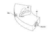
また、第2蓋部40は、図8および図12に示すように、第2試薬テーブル12(第2試薬容器ラック320)に配置された試薬容器300の交換の際に取り外すことが可能なように構成されている。第2蓋部40は、第1蓋部30の外側に取り付けられ、第2試薬テーブル12の上方に取り付けられる。また、第2蓋部40の大きさおよび形状は、第2蓋部40を取り外した状態で第2試薬容器ラック320を1つだけ取り出すことが可能に形成されている。また、図13および図14に示すように、第2蓋部40のロック機構41は、通常使用時、または、試薬の交換が終了した後に、第2蓋部40が外れないようにロックするとともに、第2試薬テーブル12における試薬の交換または追加が終了したことを制御部4aに認識させるために設けられている。  Further, as shown in FIGS. 8 and 12, thesecond lid 40 can be removed when thereagent container 300 arranged on the second reagent table 12 (second reagent container rack 320) is replaced. It is configured. Thesecond lid portion 40 is attached to the outside of thefirst lid portion 30 and attached above the second reagent table 12. Further, the size and shape of thesecond lid portion 40 are formed such that only one secondreagent container rack 320 can be taken out with thesecond lid portion 40 removed. As shown in FIGS. 13 and 14, thelocking mechanism 41 of thesecond lid 40 locks thesecond lid 40 so that thesecond lid 40 does not come off during normal use or after the reagent replacement is completed. The second reagent table 12 is provided to allow thecontrol unit 4a to recognize that the replacement or addition of the reagent has ended.

第2蓋部40のロック機構41は、図13および図14に示すように、回動軸42aを中心にユーザが回動操作可能なハンドル42と、回動軸42aを中心にハンドル42と一体的に回動される二股の中継部材43と、中継部材43と係合するとともに、回動軸44aを中心に回動可能なロック部材44と、中継部材43と係合するとともに、回動軸45aを中心に回動可能なロック検知用部材45とから構成されている。また、ロック部材44には、中継部材43と逆側の端部に凸状のロック部44b(図10参照)が設けられている。また、ロック検知用部材45には、中継部材43と逆側の端部に、第2蓋部40のロック状態で検知部50のマイクロスイッチ52aを押圧する押圧片45b(図10参照)が設けられている。また、第2蓋部40が取り付けられる第2蓋部取付部46(図13および図14参照)には、ロック部44bに対応する位置に、ロック部44bと係合される係合穴46aが設けられている。  As shown in FIGS. 13 and 14, thelock mechanism 41 of thesecond lid portion 40 is integrated with thehandle 42 that can be rotated by the user around therotation shaft 42a and thehandle 42 around therotation shaft 42a. Engaging with therelay member 43 and therelay member 43 that are pivotally rotated, and engaging with thelock member 44 and therelay member 43 that are rotatable about therotation shaft 44a. It is comprised from themember 45 for lock detection which can be rotated centering on 45a. Further, thelock member 44 is provided with aconvex lock portion 44 b (see FIG. 10) at the end opposite to therelay member 43. Further, thelock detecting member 45 is provided with apressing piece 45b (see FIG. 10) that presses themicro switch 52a of the detectingunit 50 in the locked state of thesecond lid 40 at the end opposite to therelay member 43. It has been. Further, the second lid mounting portion 46 (see FIGS. 13 and 14) to which thesecond lid 40 is attached has anengagement hole 46a that engages with the lockingportion 44b at a position corresponding to the lockingportion 44b. Is provided.

図13に示すロック解除状態からハンドル42が回動軸42aを中心に矢印C方向に回動されると、中継部材43も回動軸42aを中心に矢印C方向に回動される。また、中継部材43とロック部材44とは係合されているため、中継部材43が矢印C方向に回動されるのに伴い、ロック部材44は、回動軸44aを中心に矢印D方向に回動される。これにより、ロック部材44のロック部44bが第2蓋部取付部46の係合穴46aと係合され、ロック状態となる。  When thehandle 42 is rotated in the direction of arrow C about therotation shaft 42a from the unlocked state shown in FIG. 13, therelay member 43 is also rotated in the direction of arrow C about therotation shaft 42a. Further, since therelay member 43 and thelock member 44 are engaged, as therelay member 43 is rotated in the direction of the arrow C, thelock member 44 is moved in the direction of the arrow D around therotation shaft 44a. It is rotated. As a result, thelock portion 44b of thelock member 44 is engaged with theengagement hole 46a of the secondlid mounting portion 46, and a locked state is established.

なお、ロック状態でユーザが第2蓋部40を取り外そうとした場合に、ロック部材44のロック部44bと第2蓋部取付部46の係合穴46aとが引っ掛かることによって、第2蓋部40が外れることが抑制される。  In addition, when the user tries to remove thesecond lid portion 40 in the locked state, thelock portion 44b of thelock member 44 and theengagement hole 46a of the second lidportion attachment portion 46 are caught, whereby the second lid Thepart 40 is prevented from coming off.

また、検知部50は、第1蓋部30および第2蓋部40のロック状態をそれぞれ検知するための第1検知部51および第2検知部52を含む。第1検知部51は、マイクロスイッチ51aと、板バネ部51bとを含む。また、第2検知部は、マイクロスイッチ52aと、板バネ部52bとを含む。  Moreover, thedetection part 50 contains the1st detection part 51 and the2nd detection part 52 for detecting the locked state of the1st cover part 30 and the2nd cover part 40, respectively. Thefirst detection unit 51 includes amicro switch 51a and aleaf spring portion 51b. Further, the second detection unit includes amicro switch 52a and aleaf spring portion 52b.

第1検知部51は、図13および図14に示すように、マイクロスイッチ51aが、第1蓋部30のロック機構31の押圧片35bにより押圧された板バネ部51bによって押し込まれることによって、第1蓋部30のロック状態を検知するように構成されている。具体的には、上述のように、第1蓋部30のロックが行われる際に、ハンドル32とともに矢印A方向に回動された中継部材33により、中継部材33と係合されているロック検知用部材35は、回動軸35aを中心に矢印E方向に回動される。これにより、ロック検知用部材35の押圧片35bが矢印E方向に回動されて第1検知部51の板バネ部51bと係合されるので、マイクロスイッチ51aが第1検知部51の板バネ部51bによって押し込まれる。また、この状態で、ロック機構31のフック部34bは、円柱状の係合部6aと係合されているため、第1検知部51により第1蓋部30のロック状態が検知される。また、第1検知部51は、第1蓋部30のロック状態を検知した場合、第1蓋部30がロックされたことを表す信号を制御部4aに送るように構成されている。  As shown in FIGS. 13 and 14, thefirst detection unit 51 is configured such that themicroswitch 51 a is pushed by theleaf spring portion 51 b pressed by thepressing piece 35 b of thelock mechanism 31 of thefirst lid portion 30. It is configured to detect the locked state of onelid 30. Specifically, as described above, when thefirst lid 30 is locked, the lock detection engaged with therelay member 33 by therelay member 33 rotated in the direction of arrow A together with thehandle 32. Themember 35 is rotated in the direction of arrow E about therotation shaft 35a. As a result, thepressing piece 35b of thelock detecting member 35 is rotated in the direction of arrow E and engaged with theleaf spring portion 51b of the first detectingportion 51, so that themicro switch 51a is moved to the leaf spring of the first detectingportion 51. It is pushed in by thepart 51b. Further, in this state, thehook portion 34 b of thelock mechanism 31 is engaged with thecylindrical engagement portion 6 a, so that thefirst detection portion 51 detects the locked state of thefirst lid portion 30. Moreover, the1st detection part 51 is comprised so that the signal showing that the1st cover part 30 was locked may be sent to thecontrol part 4a, when the locked state of the1st cover part 30 is detected.

また、同様に、第2検知部52は、マイクロスイッチ52aが、第2蓋部40のロック機構41の押圧片45bにより押圧された板バネ部52bによって押し込まれることによって、第2蓋部40のロック状態を検知するように構成されている。具体的には、第2蓋部40のロックが行われる際に、ハンドル42とともに矢印C方向に回動された中継部材43により、中継部材43と係合されているロック検知用部材45は、回動軸45aを中心に矢印F方向に回動される。これにより、ロック検知用部材45の押圧片45bが矢印F方向に回動されて第2検知部52の板バネ部52bと係合されるので、マイクロスイッチ52aが第2検知部52の板バネ部52bによって押し込まれる。また、この状態で、ロック機構41のロック部44は、第2蓋部取付部46の係合穴46aと係合されているため、第2検知部52により第2蓋部40のロック状態が検知される。また、第2検知部52は、第2蓋部40のロック状態を検知した場合、第2蓋部40がロックされたことを表す信号を制御部4aに送るように構成されている。  Similarly, thesecond detection unit 52 is configured such that themicro switch 52a is pushed by theleaf spring portion 52b pressed by thepressing piece 45b of thelock mechanism 41 of thesecond lid portion 40. It is configured to detect a lock state. Specifically, when thesecond lid 40 is locked, thelock detection member 45 engaged with therelay member 43 by therelay member 43 rotated in the direction of arrow C together with thehandle 42 is It is rotated in the direction of arrow F around therotation shaft 45a. Accordingly, thepressing piece 45b of thelock detection member 45 is rotated in the direction of arrow F and engaged with theleaf spring portion 52b of thesecond detection portion 52, so that themicro switch 52a is moved to the leaf spring of thesecond detection portion 52. It is pushed in by thepart 52b. Further, in this state, thelock portion 44 of thelock mechanism 41 is engaged with theengagement hole 46 a of the secondlid attachment portion 46, so that thesecond lid 40 is locked by thesecond detector 52. Detected. Moreover, the2nd detection part 52 is comprised so that the signal showing that the2nd cover part 40 was locked may be sent to thecontrol part 4a, when the locked state of the2nd cover part 40 is detected.

また、通知部60は、3つのLEDインジケータ61、62および63を含む。図1および図3に示すように、3つのLEDインジケータ61、62および63は、第2蓋部40の近傍に所定の間隔を隔てて一列状に配置されており、試料分析装置1の外部からユーザが視認可能である。また、LEDインジケータ61、62および63は、青色または赤色に発光可能である。  Thenotification unit 60 includes threeLED indicators 61, 62, and 63. As shown in FIGS. 1 and 3, the threeLED indicators 61, 62, and 63 are arranged in a row at a predetermined interval in the vicinity of thesecond lid portion 40, and from the outside of thesample analyzer 1. Visible to the user. Further, theLED indicators 61, 62 and 63 can emit blue or red light.

LEDインジケータ61は、ユーザが試薬配置画面410において指定した第1試薬テーブル11の試薬に対応する第1試薬容器ラック310が、試薬の交換が可能な取出位置(第1蓋部30の下方)に移動されたことをユーザに通知する機能を有する。具体的には、第1試薬テーブル11が回転移動中には、LEDインジケータ61は、赤色に発光し、指定された第1試薬テーブル11の試薬に対応する第1試薬容器ラック310が取出位置に移動されて停止した時には、青色に発光するように構成されている。これにより、ユーザに、試薬の交換または追加のために第1蓋部30を取り外すタイミングを通知することが可能である。  TheLED indicator 61 is located at the take-out position (below the first lid 30) where the firstreagent container rack 310 corresponding to the reagent in the first reagent table 11 specified by the user on thereagent arrangement screen 410 can be replaced. It has a function of notifying the user that it has been moved. Specifically, while the first reagent table 11 is rotating, theLED indicator 61 emits red light, and the firstreagent container rack 310 corresponding to the reagent of the designated first reagent table 11 is at the take-out position. When it is moved and stopped, it is configured to emit blue light. Thereby, it is possible to notify a user of the timing which removes the1st cover part 30 for replacement | exchange or addition of a reagent.

また、LEDインジケータ62は、ユーザが試薬配置画面410において指定した第2試薬テーブル12の試薬に対応する第2試薬容器ラック320が、試薬の交換が可能な取出位置(第2蓋部40の下方)に移動されたことをユーザに通知する機能を有する。LEDインジケータ62は、LEDインジケータ61と同様に、第2試薬テーブル12が回転移動中には赤色に発光し、指定された第2試薬テーブル12の試薬に対応する第2試薬容器ラック320が取出位置に移動されて停止した時には、青色に発光するように構成されている。  In addition, theLED indicator 62 is an extraction position where the secondreagent container rack 320 corresponding to the reagent of the second reagent table 12 specified on thereagent arrangement screen 410 by the user can be replaced (below thesecond lid 40). ) To notify the user that it has been moved. Similarly to theLED indicator 61, theLED indicator 62 emits red light while the second reagent table 12 is rotationally moved, and the secondreagent container rack 320 corresponding to the reagent of the designated second reagent table 12 is in the take-out position. It is configured to emit blue light when it is moved to stop.

また、LEDインジケータ63は、後述するキュベット搬送テーブル71の動作状況をユーザに通知する機能を有する。すなわち、ユーザは、所定の物質を測定する場合において、専用のキュベット(図示せず)をキュベット搬送テーブル71に追加または交換する際に、キュベット搬送テーブル71の上方に位置する蓋73(図8参照)を取り外すタイミングをLEDインジケータ63によって確認可能である。キュベット搬送テーブル71が回転中である時には、LEDインジケータ63は、赤色に発光し、キュベット搬送テーブル71が停止中である時には、LEDインジケータ63は、青色に発光するように構成されている。  TheLED indicator 63 has a function of notifying the user of the operation status of a cuvette transport table 71 described later. That is, when a user measures a predetermined substance, when a dedicated cuvette (not shown) is added to or exchanged with the cuvette transport table 71, thelid 73 positioned above the cuvette transport table 71 (see FIG. 8). ) Can be confirmed by theLED indicator 63. When the cuvette transport table 71 is rotating, theLED indicator 63 emits red light. When the cuvette transport table 71 is stopped, theLED indicator 63 emits blue light.

ここで、本実施形態では、試薬の交換または追加が終了した後、第1蓋部30または第2蓋部40のロックがユーザにより行われると、試料分析装置1は、自動的に、交換された試薬が保持される第1試薬容器ラック310または第2試薬容器ラック320に保持される全ての試薬容器300のバーコード300aの読み取りが行われるように構成されている。これにより、たとえば、1つの試薬を指定して試薬の交換を指示した際に、指定した試薬に加えて、同じ第1試薬容器ラック310または第2試薬容器ラック320に保持される指定した試薬以外の試薬も交換した場合にも、交換後の試薬の配置が正しく試薬配置画面410に反映される。  Here, in the present embodiment, after the replacement or addition of the reagent is completed, when thefirst lid 30 or thesecond lid 40 is locked by the user, thesample analyzer 1 is automatically replaced. Thebarcode 300a of all thereagent containers 300 held in the firstreagent container rack 310 or the secondreagent container rack 320 in which the reagent is held is configured to be read. Thus, for example, when one reagent is designated and reagent replacement is instructed, in addition to the designated reagent, other than the designated reagent held in the same firstreagent container rack 310 or secondreagent container rack 320 When the reagent is also replaced, the reagent arrangement after the replacement is correctly reflected on thereagent arrangement screen 410.

また、測定機構部2は、さらに、図3〜図5に示すように、キュベット搬送部70と、検体分注アーム80と、第1光学的情報取得部90と、ランプユニット100と、加温部110と、キュベット移送部120と、試薬分注アーム130と、第2光学的情報取得部140と、緊急検体セット部150と、流体部160と、キュベット供給機構部170とを備えている。  Further, as shown in FIGS. 3 to 5, themeasurement mechanism unit 2 further includes acuvette transport unit 70, asample dispensing arm 80, a first opticalinformation acquisition unit 90, alamp unit 100, and a heating unit.Unit 110,cuvette transfer unit 120,reagent dispensing arm 130, second opticalinformation acquisition unit 140, emergencysample setting unit 150,fluid unit 160, and cuvettesupply mechanism unit 170.

キュベット搬送部70は、キュベット200を試料分析装置1の各部分に搬送する機能を有する。キュベット搬送部70は、円環形状の第2試薬テーブル12の外側に配置された円環形状のキュベット搬送テーブル71と、キュベット搬送テーブル71上に円周方向に沿って所定の間隔を隔てて設けられた円筒形状の複数のキュベット保持部72と、キュベット搬送テーブル71の上方に設けられる蓋73(図8参照)とからなる。キュベット保持部72は、キュベット200を1つずつ保持するために設けられている。また、蓋73には、穴部73aが設けられており、後述する検体分注アーム80によって、穴部73aを介して、キュベット200に検体が分注される。キュベット搬送テーブル71のキュベット保持部72に保持されたキュベット200(図5参照)には、搬送機構部3の試験管250に収容されている検体および試薬保存部6に保存されている試薬が分注され、測定用試料が調製される。  Thecuvette transport unit 70 has a function of transporting thecuvette 200 to each part of thesample analyzer 1. Thecuvette transport unit 70 is provided on the cuvette transport table 71 on the outer side of the annular second reagent table 12 and on the cuvette transport table 71 at a predetermined interval along the circumferential direction. And a lid 73 (see FIG. 8) provided above the cuvette transport table 71. Thecuvette holder 72 is provided to hold thecuvettes 200 one by one. Thelid 73 is provided with ahole 73a, and a sample is dispensed to thecuvette 200 via thehole 73a by asample dispensing arm 80 described later. In the cuvette 200 (see FIG. 5) held in thecuvette holding section 72 of the cuvette transfer table 71, the sample stored in thetest tube 250 of thetransfer mechanism section 3 and the reagent stored in thereagent storage section 6 are distributed. A sample for measurement is prepared.

検体分注アーム80は、搬送機構部3により吸引位置2aに搬送された試験管250に収容される検体を吸引するとともに、吸引した検体をキュベット搬送テーブル71のキュベット保持部72に保持されたキュベット200内に、穴部73aを介して分注する機能を有している。  Thesample dispensing arm 80 sucks the sample stored in thetest tube 250 transported to thesuction position 2 a by thetransport mechanism unit 3, and also holds the suctioned sample in thecuvette holding unit 72 of the cuvette transport table 71. 200 has a function of dispensing through thehole 73a.

第1光学的情報取得部90は、試薬を添加する前の検体中の干渉物質(乳び、ヘモグロビンおよびビリルビン)の有無およびその濃度を測定するために、検体から光学的な情報を取得するように構成されている。具体的には、後述するランプユニット100から照射される5種類の光(340nm、405nm、575nm、660nmおよび800nm)の内の4種類の光(405nm、575nm、660nmおよび800nm)を用いて、干渉物質の有無およびその濃度を測定している。なお、405nmの波長を有する光は、乳び、ヘモグロビンおよびビリルビンのいずれにも吸収される光である。すなわち、405nmの波長を有する光により測定された光学的な情報には、乳び、ヘモグロビンおよびビリルビンの影響が寄与している。また、575nmの波長を有する光は、ビリルビンには実質的に吸収されず、かつ、乳びおよびヘモグロビンに吸収される光である。すなわち、575nmの波長を有する光により測定された光学的な情報には、乳びおよびヘモグロビンの影響が寄与している。そして、660nmおよび800nmの波長を有する光は、ビリルビンおよびヘモグロビンには実質的に吸収されず、かつ、乳びに吸収される光である。すなわち、660nmおよび800nmの波長を有する光により測定された光学的な情報には、乳びの影響が寄与している。また、乳びは、底波長域の405nmから高波長域の800nmまでの波長の光を吸収しており、660nmの波長を有する光の方が、800nmの波長を有する光に比べて、乳びによる吸収が多い。すなわち、800nmの波長を有する光で測定した光学的な情報の方が、660nmの波長を有する光で測定した光学的な情報より、乳びの影響が小さい。  The first opticalinformation acquisition unit 90 acquires optical information from the specimen in order to measure the presence and concentration of interfering substances (chyle, hemoglobin, and bilirubin) in the specimen before adding the reagent. It is configured. Specifically, interference is performed using four types of light (405 nm, 575 nm, 660 nm, and 800 nm) among five types of light (340 nm, 405 nm, 575 nm, 660 nm, and 800 nm) emitted from thelamp unit 100 described later. The presence of substance and its concentration are measured. In addition, the light which has a wavelength of 405 nm is light absorbed by all of chyle, hemoglobin, and bilirubin. That is, the influence of chyle, hemoglobin, and bilirubin contributes to optical information measured by light having a wavelength of 405 nm. In addition, light having a wavelength of 575 nm is light that is not substantially absorbed by bilirubin and absorbed by chyle and hemoglobin. That is, the influence of chyle and hemoglobin contributes to optical information measured by light having a wavelength of 575 nm. And the light which has a wavelength of 660 nm and 800 nm is light which is not substantially absorbed by bilirubin and hemoglobin but is absorbed by chyle. That is, the influence of chyle contributes to optical information measured by light having wavelengths of 660 nm and 800 nm. In addition, chyle absorbs light having a wavelength from 405 nm in the bottom wavelength region to 800 nm in the high wavelength region, and light having a wavelength of 660 nm is more chyle than light having a wavelength of 800 nm. Absorption due to That is, optical information measured with light having a wavelength of 800 nm is less affected by chyle than optical information measured with light having a wavelength of 660 nm.

この第1光学的情報取得部90による検体の光学的な情報の取得は、第2光学的情報取得部140による検体の光学的な測定(本測定)の前に行われる。第1光学的情報取得部90は、キュベット搬送テーブル71のキュベット保持部72に保持されたキュベット200内の検体から光学的な情報(検体の透過光による情報)を取得する。  The acquisition of the optical information of the specimen by the first opticalinformation acquisition unit 90 is performed before the optical measurement (main measurement) of the specimen by the second opticalinformation acquisition unit 140. The first opticalinformation acquisition unit 90 acquires optical information (information by the transmitted light of the sample) from the sample in thecuvette 200 held in thecuvette holding unit 72 of the cuvette transport table 71.

また、第1光学的情報取得部90は、制御装置4の制御部4aに電気的に接続されており、第1光学的情報取得部90において取得されたデータ(光学的な情報)を制御装置4の制御部4aに送信する。これにより、制御装置4において、第1光学的情報取得部90からのデータの分析(解析)が行われることにより、分岐光ファイバ101から出射される5種類の光に対するキュベット200内の検体の吸光度が求められるとともに、検体中の干渉物質の有無やその濃度などが分析される。そして、本実施形態では、検体中の干渉物質の有無やその濃度などに基づいて、後述する第2光学的情報取得部140で測定した光学的な情報を分析するか否かが判断される。  Further, the first opticalinformation acquisition unit 90 is electrically connected to thecontrol unit 4a of thecontrol device 4, and the data (optical information) acquired by the first opticalinformation acquisition unit 90 is controlled by the control device. 4 to thecontrol unit 4a. As a result, thecontrol device 4 analyzes (analyzes) the data from the first opticalinformation acquisition unit 90, and thereby the absorbance of the specimen in thecuvette 200 with respect to the five types of light emitted from the branchoptical fiber 101. And the presence / absence of the interfering substance in the sample and its concentration are analyzed. In the present embodiment, it is determined whether or not to analyze optical information measured by the second opticalinformation acquisition unit 140 described later, based on the presence or absence of the interfering substance in the sample and its concentration.

ランプユニット100は、図5に示すように、第1光学的情報取得部90および第2光学的情報取得部140で行われる光学的な測定に用いられる5種類の波長を有する光(340nm、405nm、575nm、660nmおよび800nm)を供給するために設けられている。すなわち、1つのランプユニット100が、第1光学的情報取得部90および第2光学的情報取得部140に対して共通に用いられるように構成されている。また、ランプユニット100の光は、分岐光ファイバ101および分岐光ファイバ102によって、それぞれ、第1光学的情報取得部90および第2光学的情報取得部140に供給される。  As shown in FIG. 5, thelamp unit 100 includes light (340 nm and 405 nm) having five types of wavelengths used for optical measurement performed by the first opticalinformation acquisition unit 90 and the second opticalinformation acquisition unit 140. 575 nm, 660 nm and 800 nm). That is, onelamp unit 100 is configured to be used in common for the first opticalinformation acquisition unit 90 and the second opticalinformation acquisition unit 140. The light of thelamp unit 100 is supplied to the first opticalinformation acquisition unit 90 and the second opticalinformation acquisition unit 140 by the branchoptical fiber 101 and the branchoptical fiber 102, respectively.

加温部110は、保温可能なプレート111からなり、10個の凹形状のキュベット保持部111aが設けられている。各キュベット保持部111aは、それぞれ、1つのキュベット200を保持可能であり、検体が分注されたキュベット200をキュベット保持部111aに数分間保持することによって、キュベット200内の検体を約37℃に加温する機能を有する。また、加温部110で加温された検体は、加温が終了してから一定時間内に試薬の分注および測定が行われる。これにより、検体、および、検体と試薬とから調製される測定試料の変質を抑制するとともに、測定結果を安定させることが可能である。  Theheating unit 110 includes aplate 111 capable of maintaining heat, and is provided with ten concavecuvette holding units 111a. Eachcuvette holding unit 111a can hold onecuvette 200, and the sample in thecuvette 200 is kept at about 37 ° C. by holding thecuvette 200 into which the sample is dispensed in thecuvette holding unit 111a for several minutes. Has the function of heating. In addition, the sample heated by theheating unit 110 is subjected to reagent dispensing and measurement within a predetermined time after the heating is completed. Thereby, it is possible to suppress the deterioration of the sample and the measurement sample prepared from the sample and the reagent, and to stabilize the measurement result.

また、キュベット移送部120は、キュベット200を、キュベット搬送部70と、保温部110と、第2光学的情報取得部140との間を移送させるために設けられている。キュベット移送部120は、キュベット200を把持する移送用キャッチャ部121と、移送用キャッチャ部121を移動させるための駆動部122とを含む。移送用キャッチャ部121は、駆動部122の駆動により移動領域120a内を移動可能であり、キュベット搬送部70と、加温部110と、第2光学的情報取得部140の測定用載置部141との間でキュベット200の移送を行う。また、移送用キャッチャ部121には振動機能が設けられており、キュベット200を把持した状態でキュベット200を振動させることにより、キュベット200内の検体と試薬とを攪拌することが可能である。  Thecuvette transfer unit 120 is provided to transfer thecuvette 200 between thecuvette transport unit 70, theheat retaining unit 110, and the second opticalinformation acquisition unit 140. Thecuvette transfer unit 120 includes atransfer catcher unit 121 that holds thecuvette 200 and adrive unit 122 that moves thetransfer catcher unit 121. Thetransfer catcher unit 121 can be moved in the movingregion 120 a by driving thedrive unit 122, and thecuvette transport unit 70, theheating unit 110, and themeasurement mounting unit 141 of the second opticalinformation acquisition unit 140. Thecuvette 200 is transferred between the two. Thetransfer catcher unit 121 is provided with a vibration function, and the sample and the reagent in thecuvette 200 can be agitated by vibrating thecuvette 200 while holding thecuvette 200.

試薬分注アーム130は、図3〜図5に示すように、試薬保存部6に載置された試薬容器300内の試薬をキュベット200に分注することにより、キュベット200内の検体に試薬を混合するために設けられている。具体的には、前述した試薬保存部6の外壁部20の穴部22a、22bまたは22cを介して試薬の吸引を行い、加温(37℃)が完了したキュベット200を移送用キャッチャ部121が加温部110のキュベット保持部111aから取り出し、把持した状態で、吸引した試薬をキュベット200に分注する。なお、試薬分注アーム130のピペット部分には、加温機能が設けられており、吸引された試薬は、瞬間的に約37℃に加温される。すなわち、試薬保存部6で低温(約10℃)保存されている試薬は、試薬分注アーム130によって約37℃に加温された状態で、加温が完了した約37℃の検体と混合される。このように、第1光学的情報取得部90による光学的な測定が終了した検体に試薬を添加して測定用試料が調製される。  3 to 5, thereagent dispensing arm 130 dispenses the reagent in thecuvette 200 by dispensing the reagent in thereagent container 300 placed on thereagent storage unit 6 to thecuvette 200. Provided for mixing. Specifically, the reagent is aspirated through theholes 22a, 22b, or 22c of theouter wall 20 of thereagent storage unit 6 described above, and thetransfer catcher unit 121 receives thecuvette 200 that has been heated (37 ° C.). The extracted reagent is dispensed into thecuvette 200 while being taken out from thecuvette holder 111a of theheating unit 110 and held. The pipette portion of thereagent dispensing arm 130 is provided with a heating function, and the aspirated reagent is instantaneously heated to about 37 ° C. That is, the reagent stored at a low temperature (about 10 ° C.) in thereagent storage unit 6 is mixed with the sample at about 37 ° C. where the heating is completed while being heated to about 37 ° C. by thereagent dispensing arm 130. The In this way, a sample for measurement is prepared by adding a reagent to the specimen for which optical measurement by the first opticalinformation acquisition unit 90 has been completed.

ここで、本実施形態では、試薬分注アーム130の動作中に試薬の交換が指示された場合に、指定された試薬が配置された試薬テーブルから分注対象の試薬の分注作業が行われている場合には、指定された試薬が配置された試薬テーブルからの試薬分注アーム130による分注対象の試薬の分注作業が中止される。この場合、分注対象の試薬が、指定された試薬が配置された試薬テーブルとは別の試薬テーブルにも配置されている場合には、試薬分注アーム130は、指定された試薬が配置された試薬テーブルからの分注対象の試薬の分注作業を中止し、もう一方の試薬テーブルに配置された分注対象の試薬の分注作業を中止することなく実行する。また、分注対象の試薬が、交換が指示された試薬が配置された試薬テーブルにのみ配置されている場合には、試薬分注アーム130は、交換指示時に分注済みの検体(試薬分注待機中の検体)および加温部110において加温中の検体(試薬分注待機中の検体)に対する分注対象の試薬の分注を終了させてから分注動作を停止するように構成されている。これにより、交換指示時に分注済みの検体は、加温部110において加温され、加温後、一定時間内に測定が行われる。同様に、交換指示時に加温部110において加温中の検体も、加温後、一定時間内に測定が行われる。  Here, in this embodiment, when the reagent replacement is instructed during the operation of thereagent dispensing arm 130, the dispensing operation of the reagent to be dispensed is performed from the reagent table in which the designated reagent is arranged. If so, the dispensing operation of the reagent to be dispensed by thereagent dispensing arm 130 from the reagent table in which the designated reagent is arranged is stopped. In this case, when the reagent to be dispensed is also arranged in a reagent table different from the reagent table in which the designated reagent is arranged, thereagent dispensing arm 130 is arranged with the designated reagent. The dispensing operation of the reagent to be dispensed from the reagent table is stopped, and the dispensing operation of the reagent to be dispensed arranged in the other reagent table is executed without stopping. In addition, when the reagent to be dispensed is arranged only in the reagent table in which the reagent instructed to be exchanged is arranged, thereagent dispensing arm 130 displays the dispensed sample (reagent dispensing) at the time of the exchange instruction. The dispensing operation is stopped after the dispensing of the reagent to be dispensed with respect to the sample (waiting sample) and the warming sample (sample waiting for reagent dispensing) in theheating unit 110 is completed. Yes. As a result, the sample dispensed at the time of the replacement instruction is heated in theheating unit 110, and measurement is performed within a predetermined time after the heating. Similarly, the sample being heated in theheating unit 110 at the time of replacement is also measured within a certain time after heating.

第2光学的情報取得部140は、測定用試料から光学的な情報を測定するための機能を有している。この第2光学的情報取得部140は、図5に示すように、キュベット載置部141と、キュベット載置部141の下方に配置された検出部142とにより構成されている。  The second opticalinformation acquisition unit 140 has a function for measuring optical information from the measurement sample. As illustrated in FIG. 5, the second opticalinformation acquisition unit 140 includes acuvette placement unit 141 and adetection unit 142 disposed below thecuvette placement unit 141.

また、第2光学的情報取得部140の検出部142は、キュベット200内の測定用試料に対して複数の条件下で光学的な測定(本測定)を行うことが可能なように構成されている。また、第2光学的情報取得部140は、制御装置4の制御部4aに電気的に接続されており、取得したデータ(光学的な情報)を制御装置4の制御部4aに送信する。これにより、制御装置4において、予め取得済みの第1光学的情報取得部90からのデータ(光学的な情報)の分析結果に基づいて、第2光学的情報取得部140から送信されたデータ(光学的な情報)が分析されて、表示部4bに表示される。  Thedetection unit 142 of the second opticalinformation acquisition unit 140 is configured to perform optical measurement (main measurement) on the measurement sample in thecuvette 200 under a plurality of conditions. Yes. The second opticalinformation acquisition unit 140 is electrically connected to thecontrol unit 4 a of thecontrol device 4 and transmits the acquired data (optical information) to thecontrol unit 4 a of thecontrol device 4. Thereby, in thecontrol device 4, based on the analysis result of the data (optical information) from the first opticalinformation acquisition unit 90 that has been acquired in advance, the data transmitted from the second optical information acquisition unit 140 ( Optical information) is analyzed and displayed on thedisplay unit 4b.

なお、分岐光ファイバ102から照射される660nmの波長を有する光は、Fbg(フィブリノーゲン量)、PT(プロトロンビン時間)およびAPTT(活性化部分トロンボプラスチン時間)を測定する際に用いられるメイン波長である。また、800nmの波長を有する光は、Fbg、PTおよびAPTTを測定する際に用いられるサブ波長である。合成基質法の測定項目であるATIIIの測定波長は405nmであり、免疫比濁法の測定項目であるDダイマーおよびFDPの測定波長は800nmである。また、血小板凝集の測定波長は、575nmである。  The light having a wavelength of 660 nm emitted from the branchedoptical fiber 102 is a main wavelength used when measuring Fbg (fibrinogen amount), PT (prothrombin time), and APTT (activated partial thromboplastin time). In addition, light having a wavelength of 800 nm is a sub-wavelength used when measuring Fbg, PT, and APTT. The measurement wavelength of ATIII which is a measurement item of the synthetic substrate method is 405 nm, and the measurement wavelength of D dimer and FDP which are measurement items of the immunoturbidimetric method is 800 nm. The measurement wavelength of platelet aggregation is 575 nm.

緊急検体セット部150は、図3〜図5に示すように、緊急を要する検体に対しての検体分析処理を行うために設けられている。この緊急検体セット部150は、搬送機構部3から供給された検体に対しての検体分析処理が行われている際に、緊急検体を割り込ませることが可能なように構成されている。また、流体部160は、試料分析装置1のシャットダウン処理の際に、各分注アーム(検体分注アーム80および試薬分注アーム130)に設けられるノズルに洗浄液などの液体を供給するために設けられている。  As shown in FIGS. 3 to 5, the emergencysample setting unit 150 is provided for performing a sample analysis process on a sample that requires an emergency. The emergencysample setting unit 150 is configured to be able to interrupt an emergency sample when a sample analysis process is performed on the sample supplied from thetransport mechanism unit 3. Thefluid section 160 is provided to supply a liquid such as a cleaning liquid to the nozzles provided in each dispensing arm (thespecimen dispensing arm 80 and the reagent dispensing arm 130) during the shutdown process of thesample analyzer 1. It has been.

また、キュベット供給機構部170は、ユーザによって無造作に投入された複数のキュベット200をキュベット搬送部70に順次供給することが可能なように構成されている。このキュベット供給機構部170は、図3〜図5に示すように、第1ホッパ171aと、第1ホッパ171aからキュベット200が供給されるとともに、第1ホッパ171aよりも小さい第2ホッパ171bと、第2ホッパ171bからキュベット200が供給される2つの誘導板172と、2つの誘導板172の下端に配置された支持台173と、支持台173から所定の間隔を隔てて設けられた供給用キャッチャ部174とを含んでいる。第1ホッパ171a内に供給されたキュベット200は、第1ホッパ171aよりも小さい第2ホッパ171bを介して、誘導板172上を、支持台173に向かって滑り落ちながら移動するように構成されている。また、支持台173は、誘導板172を滑り落ちて移動したキュベット200を、供給用キャッチャ部174が把持可能な位置まで回転移送する機能を有している。そして、供給用キャッチャ部174は、支持台173により回転移送されたキュベット200をキュベット搬送部70に供給するために設けられている。  Thecuvette supply mechanism 170 is configured to be able to sequentially supply a plurality ofcuvettes 200 that are randomly inserted by the user to thecuvette transport unit 70. As shown in FIGS. 3 to 5, thecuvette supply mechanism 170 includes afirst hopper 171 a, acuvette 200 supplied from thefirst hopper 171 a, asecond hopper 171 b smaller than thefirst hopper 171 a, Twoguide plates 172 to which thecuvette 200 is supplied from thesecond hopper 171b, asupport base 173 disposed at the lower ends of the twoguide plates 172, and a supply catcher provided at a predetermined interval from thesupport base 173Part 174. Thecuvette 200 supplied into thefirst hopper 171a is configured to move while sliding down on theguide plate 172 toward thesupport base 173 via thesecond hopper 171b smaller than thefirst hopper 171a. Yes. In addition, thesupport base 173 has a function of rotating and transferring thecuvette 200 that has moved by sliding down theguide plate 172 to a position where thesupply catcher unit 174 can grip it. Thesupply catcher unit 174 is provided to supply thecuvette 200 rotated and transferred by thesupport base 173 to thecuvette transport unit 70.

また、図3〜図5に示すように、測定機構部2には、上述した供給用キャッチャ部174から所定の間隔を隔てて、キュベット200を廃棄するための廃棄用孔181(図3および図5参照)と、廃棄用孔181の下方に設置された廃棄ボックス182とが設けられている。上述した供給用キャッチャ部174は、キュベット搬送部70のキュベット搬送テーブル71上のキュベット200を、廃棄用孔181(図3および図5参照)を介して廃棄ボックス182に廃棄することが可能である。すなわち、供給用キャッチャ部174は、キュベット200の供給と廃棄との両方を行うことが可能である。  As shown in FIGS. 3 to 5, themeasurement mechanism unit 2 has adisposal hole 181 for discarding thecuvette 200 at a predetermined interval from thesupply catcher unit 174 described above (FIGS. 3 and 5). 5) and adisposal box 182 installed below thedisposal hole 181. Thesupply catcher unit 174 described above can discard thecuvette 200 on the cuvette conveyance table 71 of thecuvette conveyance unit 70 into thedisposal box 182 through the disposal hole 181 (see FIGS. 3 and 5). . In other words, thesupply catcher unit 174 can both supply and discard thecuvette 200.

次に、図4および図5を参照して、試料分析装置1の検体の分析動作について詳細に説明する。なお、ここでは、凝固時間法を用いた測定における動作について説明する。  Next, with reference to FIG. 4 and FIG. 5, the sample analysis operation of thesample analyzer 1 will be described in detail. Here, the operation in the measurement using the coagulation time method will be described.

まず、図4に示した試料分析装置1の測定機構部2および制御装置4の電源をそれぞれオン状態にすることにより、試料分析装置1の初期設定が行われる。これにより、キュベット200を移動させるための機構と各分注アーム(検体分注アーム80および試薬分注アーム130)とを初期位置に戻すための動作や、制御装置4の制御部4aに記憶されているソフトウェアの初期化などが行われる。  First, thesample analyzer 1 is initially set by turning on themeasurement mechanism unit 2 and thecontrol device 4 of thesample analyzer 1 shown in FIG. As a result, the mechanism for moving thecuvette 200 and each dispensing arm (sample dispensing arm 80 and reagent dispensing arm 130) are stored in thecontrol unit 4a of thecontrol device 4 and the operation for returning the initial position. The software is initialized.

そして、図5に示した搬送機構部3によって、検体を収容した試験管250が載置されたラック251の搬送が行われる。これにより、ラックセット領域3aのラック251が測定機構部2の吸引位置2aに対応する位置まで搬送される。  Thetransport mechanism 3 shown in FIG. 5 transports therack 251 on which thetest tube 250 containing the sample is placed. Thereby, therack 251 in therack setting area 3a is transported to a position corresponding to thesuction position 2a of themeasurement mechanism unit 2.

そして、検体分注アーム80により試験管250から所定量の検体の吸引が行われる。そして、検体分注アーム80をキュベット搬送部70のキュベット搬送テーブル71に保持されたキュベット200の上方に移動させる。その後、検体分注アーム80からキュベット搬送テーブル71のキュベット200内に検体が吐出されることにより、キュベット200内に検体が分取される。  Then, a predetermined amount of sample is aspirated from thetest tube 250 by thesample dispensing arm 80. Then, thespecimen dispensing arm 80 is moved above thecuvette 200 held on the cuvette transport table 71 of thecuvette transport unit 70. Thereafter, the sample is dispensed into thecuvette 200 by discharging the sample from thesample dispensing arm 80 into thecuvette 200 of the cuvette transport table 71.

そして、キュベット搬送テーブル71を回転させて、検体が分注されたキュベット200を第1光学的情報取得部90による測定が可能な位置に搬送する。これにより、第1光学的情報取得部90による検体に対する光学的な測定が行われて、検体から光学的な情報が取得される。具体的には、キュベット搬送テーブル71のキュベット保持部72(図5参照)に保持されたキュベット200内の検体を透過した5種類(340nm、405nm、575nm、660nmおよび800nm)の光による電気信号のデータを制御装置4の制御部4aに送信する。これにより、第1光学的情報取得部90による検体に対する光学的な情報(第1光学的情報)の取得が完了する。  Then, the cuvette transport table 71 is rotated to transport thecuvette 200 into which the sample has been dispensed to a position where measurement by the first opticalinformation acquisition unit 90 is possible. Thereby, the optical measurement with respect to the sample is performed by the first opticalinformation acquisition unit 90, and optical information is acquired from the sample. Specifically, electrical signals of five types (340 nm, 405 nm, 575 nm, 660 nm and 800 nm) of light transmitted through the specimen in thecuvette 200 held in the cuvette holding unit 72 (see FIG. 5) of the cuvette transport table 71 are transmitted. Data is transmitted to thecontrol unit 4a of thecontrol device 4. Thereby, the acquisition of the optical information (first optical information) for the specimen by the first opticalinformation acquisition unit 90 is completed.

そして、制御装置4の制御部4aは、受信したデータ(第1光学的情報)を用いて、検体の吸光度を算出するとともに、検体中の干渉物質(乳び、ヘモグロビン、ビリルビン)の有無およびその濃度を算出する。具体的には、ランプユニット100から照射される4種類(405nm、575nm、660nmおよび800nm)の光を用いて取得された光学的な情報(第1光学的情報)に基づいて、制御装置4の制御部4aは、検体の吸光度を算出し、この吸光度をRAM401cに記憶する。  Then, thecontrol unit 4a of thecontrol device 4 uses the received data (first optical information) to calculate the absorbance of the sample, and the presence / absence of an interfering substance (chyle, hemoglobin, bilirubin) in the sample. Calculate the concentration. Specifically, based on optical information (first optical information) acquired using four types of light (405 nm, 575 nm, 660 nm, and 800 nm) emitted from thelamp unit 100, Thecontrol unit 4a calculates the absorbance of the sample and stores this absorbance in theRAM 401c.

その後、RAM401cに記憶されている吸光度のうち、メイン波長での吸光度が閾値以下か否かが判断される。具体的には、検体の検査項目が「PT」、「APTT」、「Fbg」等の凝固時間法の検査項目の場合には、これらの項目のメイン波長である660nmを有する光を照射して測定された第1光学的情報から算出した吸光度が閾値(たとえば、2.0)以下か否かが判断される。  Thereafter, it is determined whether or not the absorbance at the main wavelength among the absorbances stored in theRAM 401c is equal to or less than a threshold value. Specifically, when the test item of the specimen is a test item of the coagulation time method such as “PT”, “APTT”, “Fbg”, etc., light having 660 nm which is the main wavelength of these items is irradiated. It is determined whether or not the absorbance calculated from the measured first optical information is a threshold value (for example, 2.0) or less.

そして、第1光学的情報取得部90で測定された第1光学的情報から算出したメイン波長での吸光度が閾値以下の場合には、キュベット200は、キュベット移送部120により、キュベット搬送テーブル71から加温部110に移送される。そして、加温部110において約37℃になった検体を収容したキュベット200は、キュベット移送部120の移送用キャッチャ部121によって把持される。そして、移送用キャッチャ部121によってキュベット200が把持された状態で、試薬分注アーム130を駆動させて、試薬テーブル(第1試薬テーブル11または第2試薬テーブル12)に載置された試薬容器300内の試薬をキュベット200内の検体に添加する。この状態で、移送用キャッチャ部121の振動機能により、キュベット200内の検体および試薬が攪拌される。これにより、測定用試料の調製が行われる。そして、そのまま、キュベット移送部120により、測定用試料が収容されたキュベット200を第2光学的情報取得部140のキュベット載置部141に移動させる。  When the absorbance at the main wavelength calculated from the first optical information measured by the first opticalinformation acquisition unit 90 is less than or equal to the threshold value, thecuvette 200 is removed from the cuvette transport table 71 by thecuvette transfer unit 120. It is transferred to theheating unit 110. Then, thecuvette 200 containing the specimen that has reached about 37 ° C. in theheating unit 110 is held by thetransfer catcher unit 121 of thecuvette transfer unit 120. Then, in a state where thecuvette 200 is gripped by thetransfer catcher unit 121, thereagent dispensing arm 130 is driven and thereagent container 300 placed on the reagent table (the first reagent table 11 or the second reagent table 12). The reagent inside is added to the specimen in thecuvette 200. In this state, the specimen and the reagent in thecuvette 200 are agitated by the vibration function of thetransfer catcher unit 121. Thereby, the sample for a measurement is prepared. Then, thecuvette 200 containing the measurement sample is moved to thecuvette placement unit 141 of the second opticalinformation acquisition unit 140 by thecuvette transfer unit 120 as it is.

そして、第2光学的情報取得部140の検出部142によりキュベット200内の測定用試料に対して複数の条件下で光学的な測定(本測定)が行われることによって、測定用試料から光学的な情報(第2光学的情報)が取得される。具体的には、まず、キュベット載置部141のキュベット200へ、ランプユニット100の分岐光ファイバ102から光が照射される。なお、分岐光ファイバ132からは、5つの異なる波長(340nm、405nm、575nm、660nmおよび800nm)の光が照射される。これにより、分岐光ファイバ102から照射され、キュベット200およびキュベット200内の測定用試料を透過した上記各波長の光に対応する電気信号のデータが取得される。  Then, thedetection unit 142 of the second opticalinformation acquisition unit 140 performs optical measurement (main measurement) on the measurement sample in thecuvette 200 under a plurality of conditions, so that the optical measurement is performed on the measurement sample. Information (second optical information) is acquired. Specifically, first, light is irradiated from the branchoptical fiber 102 of thelamp unit 100 to thecuvette 200 of thecuvette placement unit 141. The branched optical fiber 132 is irradiated with light having five different wavelengths (340 nm, 405 nm, 575 nm, 660 nm, and 800 nm). As a result, data of electrical signals corresponding to the light of each wavelength irradiated from the branchoptical fiber 102 and transmitted through thecuvette 200 and the measurement sample in thecuvette 200 is acquired.

そして、5つの異なる波長の光に対応する電気信号のデータが、制御装置4の制御部4aに順次送信される。これにより、第2光学的情報取得部140によって測定用試料に対する光学的な情報(第2光学的情報)の取得が完了する。  Then, electrical signal data corresponding to light of five different wavelengths is sequentially transmitted to thecontrol unit 4a of thecontrol device 4. Thereby, acquisition of optical information (second optical information) for the measurement sample is completed by the second opticalinformation acquisition unit 140.

一方、第1光学的情報取得部90で測定された第1光学的情報から算出したメイン波長での吸光度が閾値より大きい場合には、第1光学的情報取得部90で測定された第1光学的情報から算出したサブ波長での吸光度が閾値以下か否かが判断される。具体的には、検体の検査項目が「PT」、「APTT」、「Fbg」等の凝固時間法の検査項目の場合には、これらの項目のサブ波長である800nmを有する光を照射して測定された第1光学的情報から算出した吸光度が閾値(たとえば、2.0)以下か否かが判断される。  On the other hand, when the absorbance at the main wavelength calculated from the first optical information measured by the first opticalinformation acquisition unit 90 is larger than the threshold value, the first optical measured by the first opticalinformation acquisition unit 90 is used. It is determined whether or not the absorbance at the sub-wavelength calculated from the target information is equal to or less than a threshold value. Specifically, when the test item of the specimen is a test item of the coagulation time method such as “PT”, “APTT”, “Fbg”, etc., light having 800 nm which is a sub wavelength of these items is irradiated. It is determined whether or not the absorbance calculated from the measured first optical information is a threshold value (for example, 2.0) or less.

そして、第1光学的情報取得部90で測定された第1光学的情報から算出したサブ波長での吸光度が閾値以下の場合には、第2光学的情報取得部140によって測定用試料に対する光学的な情報(第2光学的情報)を取得する。  If the absorbance at the sub-wavelength calculated from the first optical information measured by the first opticalinformation acquisition unit 90 is equal to or less than the threshold value, the second opticalinformation acquisition unit 140 optically measures the sample for measurement. Information (second optical information) is acquired.

また、一方、第1光学的情報取得部90で測定した第1光学的情報から算出したサブ波長での吸光度が閾値より大きい場合には、検体に含有される干渉物質(ビリルビン、ヘモグロビンおよび乳び)の影響が大きいため信頼性の高い分析を行うことが困難であると判断して、本測定を中止する。これにより、干渉物質の影響を顕著に受けた分析不能な検体に対して、試薬を添加して測定用試料を調製することがないので、試薬が無駄になるのを抑制することが可能となる。なお、信頼性の高い測定を行うことが困難な場合(本測定を中止する場合)として、第1光学的情報取得部90で検出した検体中に干渉物質が多量に存在することにより、検体を透過する光が遮られて、検体を透過する透過光を実質的に検出できない場合などが挙げられる。  On the other hand, when the absorbance at the sub-wavelength calculated from the first optical information measured by the first opticalinformation acquisition unit 90 is larger than the threshold value, interference substances (bilirubin, hemoglobin, and chyle contained in the specimen are included. ) Is determined to be difficult to perform highly reliable analysis, and the measurement is discontinued. As a result, it is possible to prevent the reagent from being wasted because a sample for measurement is not prepared by adding a reagent to a non-analyzable sample that has been significantly affected by the interference substance. . When it is difficult to perform highly reliable measurement (when this measurement is stopped), the sample detected by the first opticalinformation acquisition unit 90 has a large amount of interfering substances. For example, the transmitted light is blocked and the transmitted light transmitted through the specimen cannot be substantially detected.

そして、上記した第2光学的情報取得部140による第2光学的情報の取得(本測定)の後、第2光学的情報取得部140において測定された複数の第2光学的情報の中からメイン波長で測定した測定用試料の第2光学的情報が制御装置4の制御部4aに送信されて、その制御部4aのハードディスク401dにインストールされるアプリケーションプログラム404aにより分析される。たとえば、検体の検査項目が「PT」の場合には、まず、「PT」のメイン波長である660nmを有する光を照射して測定された第2光学的情報が制御装置4の制御部4aに送信される。その後、メイン波長で取得された第2光学的情報を受信した制御部4aが、その第2光学的情報に基づいて、分析結果を出力する。  Then, after the acquisition (main measurement) of the second optical information by the second opticalinformation acquisition unit 140, the main information is selected from the plurality of second optical information measured by the second opticalinformation acquisition unit 140. The second optical information of the measurement sample measured at the wavelength is transmitted to thecontrol unit 4a of thecontrol device 4 and analyzed by theapplication program 404a installed in thehard disk 401d of thecontrol unit 4a. For example, when the test item of the specimen is “PT”, first, the second optical information measured by irradiating light having a main wavelength of “PT” of 660 nm is transmitted to thecontrol unit 4 a of thecontrol device 4. Sent. Thereafter, thecontrol unit 4a that has received the second optical information acquired at the main wavelength outputs an analysis result based on the second optical information.

また、同様にして、上記した第2光学的情報取得部140による第2光学的情報の取得(本測定)の後、第2光学的情報取得部140において測定された複数の第2光学的情報の中からサブ波長で測定した測定用試料の第2光学的情報が制御装置4の制御部4aに送信されて、その制御部4aのハードディスク401dにインストールされるアプリケーションプログラム404aにより分析される。具体的には、検体の検査項目が「PT」の場合には、まず、「PT」のサブ波長である800nmを有する光を照射して測定された第2光学的情報が制御装置4の制御部4aに送信される。その後、サブ波長で取得された第2光学的情報を受信した制御部4aが、その第2光学的情報に基づいて、分析結果を出力する。  Similarly, a plurality of second optical information measured by the second opticalinformation acquisition unit 140 after the second opticalinformation acquisition unit 140 acquires (main measurement) the second optical information. The second optical information of the measurement sample measured at the sub-wavelength is transmitted to thecontrol unit 4a of thecontrol device 4 and analyzed by theapplication program 404a installed in thehard disk 401d of thecontrol unit 4a. Specifically, when the test item of the specimen is “PT”, first, the second optical information measured by irradiating light having a sub-wavelength of “PT” of 800 nm is controlled by thecontrol device 4. Is transmitted to theunit 4a. Thereafter, thecontrol unit 4a that has received the second optical information acquired at the sub-wavelength outputs an analysis result based on the second optical information.

そして、制御装置4の制御部4aによる分析が終了した後には、得られた分析結果を制御装置4の表示部4bに表示する。このようにして、試料分析装置1の検体の分析動作が終了する。  And after the analysis by thecontrol part 4a of thecontrol apparatus 4 is complete | finished, the obtained analysis result is displayed on thedisplay part 4b of thecontrol apparatus 4. FIG. In this way, the sample analysis operation of thesample analyzer 1 is completed.

図21は、本実施形態による試料分析装置1の制御装置4の制御部4aおよび測定機構部2の制御部501の測定処理フローを説明するためのフローチャートである。次に、図1、図3、図7および図21を参照して、本実施形態による試料分析装置1の制御部4aと制御部501との測定処理フローを説明する。  FIG. 21 is a flowchart for explaining the measurement processing flow of thecontrol unit 4a of thecontrol device 4 of thesample analyzer 1 and thecontrol unit 501 of themeasurement mechanism unit 2 according to the present embodiment. Next, with reference to FIG. 1, FIG. 3, FIG. 7, and FIG. 21, the measurement process flow of thecontrol unit 4a and thecontrol unit 501 of thesample analyzer 1 according to the present embodiment will be described.

まず、測定機構部2の電源(図示しない)を入れると、ステップS1において、制御部501の初期化(プログラムの初期化)が行われるとともに、測定機構部2の各部の動作チェックが行われる。そして、制御装置4の電源(図示しない)を入れると、ステップS11において、制御部4aの初期化(プログラムの初期化)が行われる。なお、制御部501の初期化が完了すると、制御部501は、制御部4aの初期化完了を示す初期化完了信号を要求し、初期化完了信号を受信すると、試薬保存部6にセットされた全ての試薬のバーコードおよび試薬ラックのバーコードを読み取るようにバーコードリーダ350を制御する。読み取られたバーコード情報は、制御部501から制御部4aに送信され、制御部4aのハードディスク401dに記憶される。  First, when the power supply (not shown) of themeasurement mechanism unit 2 is turned on, thecontrol unit 501 is initialized (program initialization) and the operation of each unit of themeasurement mechanism unit 2 is checked in step S1. When thecontrol device 4 is turned on (not shown), thecontrol unit 4a is initialized (program is initialized) in step S11. When the initialization of thecontrol unit 501 is completed, thecontrol unit 501 requests an initialization completion signal indicating the completion of initialization of thecontrol unit 4a. When the initialization completion signal is received, thecontrol unit 501 is set in thereagent storage unit 6. Thebarcode reader 350 is controlled to read all reagent barcodes and reagent rack barcodes. The read barcode information is transmitted from thecontrol unit 501 to thecontrol unit 4a and stored in thehard disk 401d of thecontrol unit 4a.

次に、ステップS12において、表示部4bにメニュー画面(図示せず)が表示され、ユーザがメニュー画面に表示されたスタートボタンを押すことにより、ステップS13において、測定開始信号が制御部4aから制御部501へ送信される。ステップS12において、スタートボタンが押されなかった場合には、ステップS17に進む。  Next, in step S12, a menu screen (not shown) is displayed on thedisplay unit 4b. When the user presses the start button displayed on the menu screen, the measurement start signal is controlled from thecontrol unit 4a in step S13. Transmitted to theunit 501. If the start button is not pressed in step S12, the process proceeds to step S17.

次に、ステップS2において、制御部501によって、測定開始信号の受信が行われたか否かが判断され、測定開始信号の受信が行われたと判断された場合には、ステップS3に進み、測定開始信号の受信が行われなかったと判断された場合には、ステップS6に進む。  Next, in step S2, thecontrol unit 501 determines whether or not the measurement start signal has been received. If it is determined that the measurement start signal has been received, the process proceeds to step S3 to start the measurement. If it is determined that no signal has been received, the process proceeds to step S6.

次に、ステップS3において、キュベット200に分注された検体に試薬を分注する処理が行われる。そして、ステップS4において、第1光学的情報取得部80と第2光学的情報取得部130で、試薬が分注された検体の測定が行われ、ステップS5において、測定結果が、制御部501から制御部4aに送信される。  Next, in step S3, a process of dispensing a reagent to the sample dispensed in thecuvette 200 is performed. In step S4, the first opticalinformation acquisition unit 80 and the second opticalinformation acquisition unit 130 measure the sample into which the reagent is dispensed. In step S5, the measurement result is received from thecontrol unit 501. It is transmitted to thecontrol unit 4a.

次に、ステップS14において、制御部4aによって、測定結果の受信が行われたか否かが判断され、測定結果の受信が行われた場合には、ステップS15に進み、測定結果の受信が行われなかった場合には、ステップS17に進む。そして、ステップS15において、制御部4aによって、測定結果の分析が行われ、ステップS16において、その分析結果がハードディスク401dに記憶される。  Next, in step S14, thecontrol unit 4a determines whether or not the measurement result is received. If the measurement result is received, the process proceeds to step S15, and the measurement result is received. If not, the process proceeds to step S17. In step S15, the measurement result is analyzed by thecontrol unit 4a. In step S16, the analysis result is stored in thehard disc 401d.

次に、ステップS17において、制御部4aによって、試薬配置画面410の表示指示が行われたか否か(メニュー画面から試薬配置画面410を表示するための試薬ボタン(図示せず)が押されたか否か)が判断され、試薬配置画面410の表示指示が行われた場合には、ステップS18に進み、試薬配置画面410の表示指示が行われなかった場合には、ステップS23に進む。そして、ステップS18において、制御部4aによって、試薬配置画面410の表示が行われる。試薬配置画面410が表示される際、制御部4aによって、読み取られたバーコード情報(ステップS1)に基づいて、試薬配置画面410に表示された第1試薬表示領域421、第2試薬表示領域422および試薬情報表示領域430に必要な情報が反映される(図7参照)。  Next, in step S17, whether or not a display instruction for thereagent arrangement screen 410 has been issued by thecontrol unit 4a (whether a reagent button (not shown) for displaying thereagent arrangement screen 410 has been pressed from the menu screen). When the display instruction of thereagent arrangement screen 410 is performed, the process proceeds to step S18. When the display instruction of thereagent arrangement screen 410 is not performed, the process proceeds to step S23. In step S18, thereagent arrangement screen 410 is displayed by thecontrol unit 4a. When thereagent arrangement screen 410 is displayed, the firstreagent display area 421 and the secondreagent display area 422 displayed on thereagent arrangement screen 410 based on the barcode information (step S1) read by thecontrol unit 4a. The necessary information is reflected in the reagent information display area 430 (see FIG. 7).

次に、ステップS19において、タッチパネル機構を有する表示部4bの試薬配置画面410において、制御部4aによって、交換する試薬の指定が行われた否かが判断される。以下に試薬の指定の詳細を説明する。すなわち、ユーザは、まず、図7に示した試薬配置画面410の試薬配置表示領域420を参照することにより、試薬の配置を確認する。また、ユーザは、複数の第1試薬表示領域421または第2試薬表示領域422の中から試薬が表示されている第1試薬表示領域421または第2試薬表示領域422を直接手で触れることにより任意の試薬を選択して、試薬情報表示領域430に表示される選択した試薬の属性情報を確認する。そして、交換しようとする試薬をユーザが決定した後、交換しようとする試薬が表示されている第1試薬表示領域421または第2試薬表示領域422がユーザにより選択される。ステップS19において、制御部4aによって、試薬の指定が行われたと判断された場合には、ステップS20に進み、試薬の指定が行われなかったと判断された場合には、ステップS23に進む。図7では、試薬位置「A15−6」の試薬「PT−TPC+」が指定されているとともに、試薬情報表示領域430には、試薬「PT−TPC+」の属性情報が表示されている。  Next, in step S19, on thereagent arrangement screen 410 of thedisplay unit 4b having a touch panel mechanism, it is determined whether or not the reagent to be replaced has been designated by thecontrol unit 4a. Details of the reagent designation will be described below. That is, the user first confirms the reagent arrangement by referring to the reagentarrangement display area 420 of thereagent arrangement screen 410 shown in FIG. In addition, the user arbitrarily touches the firstreagent display area 421 or the secondreagent display area 422 on which the reagent is displayed from the plurality of firstreagent display areas 421 or the secondreagent display areas 422 by hand. And the attribute information of the selected reagent displayed in the reagentinformation display area 430 is confirmed. Then, after the user determines the reagent to be replaced, the user selects the firstreagent display area 421 or the secondreagent display area 422 in which the reagent to be replaced is displayed. In step S19, if it is determined by thecontrol unit 4a that the reagent has been designated, the process proceeds to step S20. If it is determined that the reagent has not been designated, the process proceeds to step S23. In FIG. 7, the reagent “PT-TPC +” at the reagent position “A15-6” is designated, and the attribute information of the reagent “PT-TPC +” is displayed in the reagentinformation display area 430.

次に、ステップS20において、試薬交換の指示が行われたと判断された場合には、ステップS21において、試薬交換信号が制御部4aから制御部501へ送信される。その後、ステップS22において、制御部4aによって、試薬交換処理が行われる。ステップS20において、試薬交換の指示が行われなかったと判断された場合には、ステップS23に進む。  Next, when it is determined in step S20 that a reagent replacement instruction has been performed, a reagent replacement signal is transmitted from thecontrol unit 4a to thecontrol unit 501 in step S21. Thereafter, in step S22, a reagent replacement process is performed by thecontrol unit 4a. If it is determined in step S20 that the reagent replacement instruction has not been given, the process proceeds to step S23.

次に、ステップS23において、制御部4aによって、シャットダウンの指示が行われたか否か(メニュー画面からシャットダウンボタン(図示せず)が押されたか否か)が判断され、シャットダウンの指示が行われたと判断された場合には、ステップS24に進み、シャットダウンの指示が行われなかったと判断された場合には、ステップS12に戻る。そして、ステップS24において、シャットダウン信号が制御部4aから制御部501へ送信されるとともに、制御装置4のシャットダウンが行われ、処理が終了する。  Next, in step S23, it is determined whether or not a shutdown instruction has been issued (whether or not a shutdown button (not shown) has been pressed from the menu screen), and the shutdown instruction has been issued. If it is determined, the process proceeds to step S24. If it is determined that the shutdown instruction has not been issued, the process returns to step S12. In step S24, a shutdown signal is transmitted from thecontrol unit 4a to thecontrol unit 501, and thecontrol device 4 is shut down, and the process ends.

次に、ステップS6において、制御部501によって、試薬交換信号の受信が行われたか否かが判断され、試薬交換信号の受信が行われたと判断された場合には、ステップS7に進み、試薬交換信号の受信が行われなかったと判断された場合には、ステップS8に進む。そして、ステップS7において、制御部501によって、試薬交換処理が行われる。  Next, in step S6, thecontrol unit 501 determines whether or not a reagent replacement signal has been received. If it is determined that a reagent replacement signal has been received, the process proceeds to step S7, where reagent replacement is performed. If it is determined that no signal has been received, the process proceeds to step S8. In step S7, thecontrol unit 501 performs a reagent replacement process.

次に、ステップS8において、シャットダウン信号の受信が行われたか否かが判断され、シャットダウン信号の受信が行われたと判断された場合には、ステップS9に進み、シャットダウン信号の受信が行われなかったと判断された場合には、ステップS2に戻る。そして、ステップS9において、測定機構部2のシャットダウンが行われ、処理が終了する。  Next, in step S8, it is determined whether or not the shutdown signal has been received. If it is determined that the shutdown signal has been received, the process proceeds to step S9 and the shutdown signal has not been received. If it is determined, the process returns to step S2. In step S9, themeasurement mechanism unit 2 is shut down, and the process ends.

なお、制御部501の測定処理フローおいて、ステップS3と、ステップS4と、ステップS7とは、並列処理されている。また、制御部4aの測定処理フローおいて、ステップS15と、ステップS18と、ステップS22とは、並列処理されている。  In the measurement process flow of thecontrol unit 501, step S3, step S4, and step S7 are processed in parallel. In the measurement process flow of thecontrol unit 4a, step S15, step S18, and step S22 are processed in parallel.

図22は、図21に示したフローチャートのステップS22において制御装置4の制御部4aが行う試薬交換処理の詳細を説明するためのフローチャートである。また、図23は、図21に示したフローチャートのステップS7において測定機構部2の制御部501が行う試薬交換処理の詳細を説明するためのフローチャートである。次に、図3、図7、図22および図23を参照して、本実施形態による試料分析装置1の制御部4aと制御部501の試薬交換処理フローを説明する。  FIG. 22 is a flowchart for explaining details of the reagent replacement process performed by thecontrol unit 4a of thecontrol device 4 in step S22 of the flowchart shown in FIG. FIG. 23 is a flowchart for explaining the details of the reagent replacement process performed by thecontrol unit 501 of themeasurement mechanism unit 2 in step S7 of the flowchart shown in FIG. Next, with reference to FIG. 3, FIG. 7, FIG. 22, and FIG. 23, the reagent replacement process flow of thecontrol unit 4a and thecontrol unit 501 of thesample analyzer 1 according to the present embodiment will be described.

まず、図23に示したステップS41において、制御部501によって、前述した試薬分注待機中の検体の中に、交換の指定がされた試薬を保持するラックが配置された試薬テーブル(以下、試薬交換対象テーブル)の試薬を使用するものがあるか否かが判断され、試薬交換信号を受信したときに試薬分注待機中の検体の中に試薬交換対象テーブルの試薬を使用するものがある場合には、ステップS42において、当該検体への試薬の分注を実行する。そして、ステップS41〜ステップS42を繰り返すことにより、試薬交換対象テーブルの試薬を使用する試薬分注待機中の検体に対して、試薬交換対象テーブルからの試薬の分注が全て行われる。これにより、試薬交換の指示が出されたとき試薬分注待機中の検体の中に試薬交換対象テーブルの試薬を使用する検体がある場合には、試薬交換実行前に、その検体に対して、試薬の分注が行われる。一旦、検体がキュベット200に分注されて測定が開始された場合には、その検体に対して、所定時間経過後、試薬を分注する必要があり、それが正しく行われなければ、その検体は測定に使用することができず、廃棄しなければならない。従って、測定が開始された検体(試薬分注待機中の検体)に対して、所定の処理が行われ、測定を中断することなく、測定を完了させる必要がある。また、試薬交換の指示が出されたとき試薬分注待機中の検体の中に試薬交換対象の試薬テーブルの試薬を使用する検体がない場合には、制御部501は、ステップS43以降の処理を実行し、試薬交換動作を行う。つまり、ステップS41において、試薬分注待機中の検体がないか、あったとしても、試薬交換対象テーブルの試薬を使用しない場合には、試薬交換対象テーブルにアクセスする必要がないため、試薬交換動作が実行される。以上のように、試薬交換の指示が出されたとき試薬分注待機中の検体の中に試薬交換対象テーブルの試薬を使用する検体がある場合とない場合との両方において、試薬分注待機中の検体を破棄することがないため、検体を無駄にすることがないうえ、迅速に試薬交換が可能である。  First, in step S41 shown in FIG. 23, thecontrol unit 501 arranges a reagent table (hereinafter referred to as a reagent) in which a rack holding a reagent designated for replacement is arranged in the above-described sample waiting for reagent dispensing. When there is a sample that uses the reagent in the reagent replacement table when a reagent replacement signal is received when a reagent replacement signal is received. In step S42, the reagent is dispensed into the sample. Then, by repeating Steps S41 to S42, all of the reagent from the reagent replacement target table is dispensed with respect to the specimen that is waiting for reagent dispensing using the reagent in the reagent replacement target table. As a result, if there is a sample that uses the reagent in the reagent replacement target table among the samples waiting for reagent dispensing when the reagent replacement instruction is issued, before the reagent replacement, Reagent dispensing is performed. Once the sample is dispensed into thecuvette 200 and measurement is started, the reagent needs to be dispensed to the sample after a predetermined time has elapsed. Cannot be used for measurement and must be discarded. Therefore, a predetermined process is performed on the sample for which measurement has been started (sample waiting for reagent dispensing), and it is necessary to complete the measurement without interrupting the measurement. In addition, when there is no sample using the reagent in the reagent table to be replaced, among the samples waiting for reagent dispensing when the reagent replacement instruction is issued, thecontrol unit 501 performs the processing after step S43. Execute the reagent replacement operation. That is, in step S41, even if there is no sample waiting for reagent dispensing, even if the reagent in the reagent replacement target table is not used, it is not necessary to access the reagent replacement target table, so the reagent replacement operation Is executed. As described above, when a reagent replacement instruction is issued, reagent dispensing standby is performed both in cases where there is a sample that uses the reagent in the reagent replacement target table and in the sample that is waiting for reagent dispensing. The specimen is not discarded, so that the specimen is not wasted and the reagent can be replaced quickly.

次に、ステップS41において、試薬分注待機中の全ての検体が試薬交換対象テーブルの試薬を使用しないと判断された場合には、ステップS43において、制御部501によって、第1駆動部502または第2駆動部503が制御されることにより、試薬交換対象テーブルが回転し、指定された試薬を保持する第1試薬容器ラック310または第2試薬容器ラック320が取出位置(第1蓋部30または第2蓋部40の下方)に移動される。この処理において、制御部501が試薬交換対象テーブルの駆動回路に対して移動を指示するコマンドを発する。そのコマンドをこの駆動回路が受け付けると、駆動回路が内蔵するステータスレジスタの試薬交換フラグをセットする。つまり、ユーザによって交換指示された試薬が配置された試薬交換対象テーブルについて、上記の試薬交換ステータスをオンにセットするようになっている。なお、試薬交換ステータスは、第1試薬テーブル11の試薬交換ステータスおよび第2試薬テーブル12の試薬交換ステータスのいずれか一方がオンにセットされる。そして、指定された試薬を保持する試薬容器ラックが取出位置に移動されると、ステップS44において、制御部501によって、指定された試薬を保持する試薬容器ラックが取出位置に移動されたことを示す移動終了信号が制御部4aに送信される。なお、制御部501が、第1駆動部502または第2駆動部503に供給した駆動パルス信号のパルス数をカウントすることにより、第1試薬テーブル11および第2試薬テーブル12の原点位置からの各試薬テーブル11、12の回転移動量を決定することが可能である。そのため、制御部501は、原点位置からの移動量によって、第1試薬テーブル11または第2試薬テーブル12が取出位置に移動したことを認識することが可能であり、その認識に基づいて移動終了信号を発生させる。  Next, when it is determined in step S41 that all the samples waiting for reagent dispensing do not use the reagent in the reagent replacement target table, in step S43, thecontrol unit 501 causes thefirst drive unit 502 or the first By controlling thesecond drive unit 503, the reagent replacement target table rotates, and the firstreagent container rack 310 or the secondreagent container rack 320 holding the specified reagent is taken out (thefirst lid 30 or the first lid 30). 2 below the lid 40). In this process, thecontrol unit 501 issues a command for instructing movement to the drive circuit of the reagent replacement target table. When the drive circuit accepts the command, the reagent replacement flag in the status register built in the drive circuit is set. That is, the reagent replacement status is set to ON for the reagent replacement target table in which the reagent instructed to be replaced by the user is arranged. As the reagent replacement status, one of the reagent replacement status in the first reagent table 11 and the reagent replacement status in the second reagent table 12 is set to ON. When the reagent container rack that holds the designated reagent is moved to the removal position, in step S44, thecontrol unit 501 indicates that the reagent container rack that holds the designated reagent has been moved to the removal position. A movement end signal is transmitted to thecontrol unit 4a. Thecontrol unit 501 counts the number of pulses of the drive pulse signal supplied to thefirst drive unit 502 or thesecond drive unit 503, so that each of the first reagent table 11 and the second reagent table 12 from the origin position is counted. The rotational movement amount of the reagent tables 11 and 12 can be determined. Therefore, thecontrol unit 501 can recognize that the first reagent table 11 or the second reagent table 12 has moved to the take-out position based on the movement amount from the origin position, and based on the recognition, the movement end signal Is generated.

制御部501から制御部4aに移動終了信号が送信されると、図22に示すステップS31において、制御部4aによって、移動終了信号を受信したか否かが判断される。ステップS31において移動終了信号の受信が行われた判断された場合には、ステップ32において、指定された試薬を保持する試薬容器ラックが取出位置に移動されたことをユーザに通知する。具体的には、試薬交換部7においては、指定された試薬を保持する試薬容器ラックが取出位置に移動されると、試薬容器ラックの移動中に赤色に発光していたLEDインジケータ61またはLEDインジケータ62が青色に発光する。これにより、指定された試薬を保持する試薬容器ラックが取出位置に移動されたことがユーザに通知される。  When the movement end signal is transmitted from thecontrol unit 501 to thecontrol unit 4a, thecontrol unit 4a determines whether or not the movement end signal is received in step S31 shown in FIG. If it is determined in step S31 that the movement end signal has been received, instep 32, the user is notified that the reagent container rack holding the designated reagent has been moved to the take-out position. Specifically, in thereagent replacement unit 7, when the reagent container rack that holds the designated reagent is moved to the take-out position, theLED indicator 61 or LED indicator that emits red light during the movement of the reagent container rack. 62 emits blue light. As a result, the user is notified that the reagent container rack holding the designated reagent has been moved to the removal position.

次に、試薬の交換作業のために、ユーザによって、試薬交換対象テーブルの蓋部のロック機構が解除される。そして、この蓋部のロック検知部からロック解除信号が制御部501へ送られ、ステップS45において、制御部501によって、蓋部のロックが解除されたか否かが判断される。なお、蓋部のロックの解除動作としては、第1蓋部30の場合は、第1蓋部30のハンドル32が矢印A方向(図13参照)と反対方向にユーザにより回動されることによりロックが解除される。また、第2蓋部40の場合は、第2蓋部40のハンドル42が矢印C方向(図13参照)と反対方向にユーザにより回動されることによりロックが解除される。このロックが解除されていることの判断は、以下のように行われる。すなわち、ロック状態(図14参照)からハンドル32またはハンドル42が矢印A方向と反対方向または矢印C方向と反対方向に回動されることにより、第1蓋部30または第2蓋部40のロックが解除された場合には、第1検知部51のマイクロスイッチ51aまたは第2検知部52のマイクロスイッチ52aを押し込んでいる押圧片35bまたは45bによる押圧力が解除される。これにより、第1検知部51のマイクロスイッチ51aまたは第2検知部52のマイクロスイッチ52aは、蓋部のロックが解除されたことを検知するとともに、第1検知部51または第2検知部52による検知信号が制御部501に送信される。  Next, for the reagent replacement operation, the lock mechanism of the lid portion of the reagent replacement target table is released by the user. Then, an unlock signal is sent from the lock detection unit of the lid to thecontrol unit 501, and in step S45, thecontrol unit 501 determines whether or not the lid is unlocked. As for the unlocking operation of the lid portion, in the case of thefirst lid portion 30, thehandle 32 of thefirst lid portion 30 is rotated by the user in the direction opposite to the arrow A direction (see FIG. 13). The lock is released. Moreover, in the case of the2nd cover part 40, the lock is released when thehandle 42 of the2nd cover part 40 is rotated by the user in the direction opposite to the arrow C direction (refer FIG. 13). The determination that the lock is released is performed as follows. That is, when thehandle 32 or thehandle 42 is rotated in the opposite direction to the arrow A direction or the opposite direction to the arrow C direction from the locked state (see FIG. 14), thefirst lid 30 or thesecond lid 40 is locked. Is released, the pressing force by thepressing piece 35b or 45b pressing themicro switch 51a of thefirst detection unit 51 or themicro switch 52a of thesecond detection unit 52 is released. Accordingly, themicro switch 51a of thefirst detection unit 51 or themicro switch 52a of thesecond detection unit 52 detects that the lid is unlocked, and thefirst detection unit 51 or the second detection unit 52 A detection signal is transmitted to thecontrol unit 501.

なお、ユーザによる試薬の交換作業としては、ロック状態が解除された第1蓋部30または第2蓋部40がユーザにより取り外された後、取出位置(第1蓋部30または第2蓋部40の下方)にある試薬容器ラックの把持部(把持部313または327)がユーザにより把持されて取り出される。そして、ユーザにより、指定された試薬が収容された試薬容器300が、新たな試薬が収容された試薬容器300と交換される。その後、交換後の試薬が配置された試薬容器ラックが取出位置に戻され、ユーザにより第1蓋部30または第2蓋部40が取り付けられてロックされる。なお、蓋部のロック動作としては、第1蓋部30の場合は、第1蓋部30のハンドル32が矢印A方向(図13参照)にユーザにより回動されることによりロックが行われる。また、第2蓋部40の場合は、第2蓋部40のハンドル42が矢印C方向(図13参照)にユーザにより回動されることによりロックが行われる。  As a reagent replacement operation by the user, after thefirst lid 30 or thesecond lid 40 released from the locked state is removed by the user, the removal position (thefirst lid 30 or the second lid 40) is removed. The grasping part (grippingpart 313 or 327) of the reagent container rack in the lower part) is grasped by the user and taken out. Then, the user replaces thereagent container 300 containing the designated reagent with areagent container 300 containing a new reagent. Thereafter, the reagent container rack in which the reagent after replacement is arranged is returned to the take-out position, and thefirst lid 30 or thesecond lid 40 is attached and locked by the user. As for the locking operation of the lid portion, in the case of thefirst lid portion 30, thehandle 32 of thefirst lid portion 30 is locked by being rotated by the user in the direction of arrow A (see FIG. 13). In the case of thesecond lid 40, thehandle 42 of thesecond lid 40 is locked by being rotated by the user in the direction of arrow C (see FIG. 13).

次に、蓋部のロック検知部からロック信号が制御部501へ送られ、ステップS46において、制御部501によって、蓋部がロックされたか否かが判断される。ステップS46におけるロックされているかどうかの判断は、以下のように行われる。すなわち、ロック解除状態(図13参照)からハンドル32またはハンドル42が矢印A方向または矢印C方向に回動されることにより、第1蓋部30または第2蓋部40がロックされた場合には、第1検知部51のマイクロスイッチ51aまたは第2検知部52のマイクロスイッチ52aが押し込まれるとともに、第1検知部51または第2検知部52による検知信号が制御部501に送信される。これにより、蓋部のロックが行われたという判断が行われる。  Next, a lock signal is sent from the lock detection unit of the lid to thecontrol unit 501, and in step S46, thecontrol unit 501 determines whether or not the lid is locked. In step S46, it is determined whether or not it is locked as follows. That is, when thefirst lid 30 or thesecond lid 40 is locked by rotating thehandle 32 or thehandle 42 in the arrow A direction or the arrow C direction from the unlocked state (see FIG. 13). Themicro switch 51a of thefirst detection unit 51 or themicro switch 52a of thesecond detection unit 52 is pushed in, and a detection signal from thefirst detection unit 51 or thesecond detection unit 52 is transmitted to thecontrol unit 501. Thereby, it is determined that the lid has been locked.

そして、ステップS46において、制御部501によって第1蓋部30または第2蓋部40がロックされたと判断された場合には、ステップS47において、バーコードの読取動作が行われる。このバーコードの読取動作では、制御部501が、交換された試薬が配置される第1試薬容器ラック310または第2試薬容器ラック320に対して、バーコードリーダ350によるバーコードの読み取りを行うように、第1試薬テーブル11または第2試薬テーブル12とバーコードリーダ350とを制御する。具体的には、第2試薬容器ラック320、および、第2試薬ラック320に保持されている試薬容器300のバーコード300a、321b〜326bまたは321c〜326cの読み取りを行う際には、第2試薬テーブル12が図5の矢印G方向(反時計回り)に回転されながら、最初に位置情報を識別するためのバーコード321bを読み取る。その後、試薬情報を識別するためのバーコード300aまたは容器無し情報を識別するためのバーコード321cを読み取り、その後、位置情報を表すバーコード322bを読み取る。このように、位置情報(バーコード321b〜326b)と位置情報に対応する試薬情報(バーコード300a)または容器無し情報(バーコード321c〜326c)とを交互に読み取っていく。  If thecontroller 501 determines in step S46 that thefirst lid 30 or thesecond lid 40 is locked, a barcode reading operation is performed in step S47. In this barcode reading operation, thecontroller 501 reads the barcode by thebarcode reader 350 with respect to the firstreagent container rack 310 or the secondreagent container rack 320 in which the replaced reagent is arranged. In addition, the first reagent table 11 or the second reagent table 12 and thebarcode reader 350 are controlled. Specifically, when reading thebarcodes 300a, 321b to 326b or 321c to 326c of the secondreagent container rack 320 and thereagent container 300 held in thesecond reagent rack 320, the second reagent While the table 12 is rotated in the direction of arrow G (counterclockwise) in FIG. 5, first, abarcode 321b for identifying position information is read. Thereafter, thebarcode 300a for identifying the reagent information or thebarcode 321c for identifying the non-container information is read, and then thebarcode 322b representing the position information is read. Thus, the position information (barcodes 321b to 326b) and the reagent information (barcode 300a) or the container absence information (barcodes 321c to 326c) corresponding to the position information are alternately read.

また、第1試薬容器ラック310、および、第1試薬容器ラック310に保持されている試薬容器300のバーコード300a、311b〜312bまたは311c〜312cの読み取りの際には、まず、第2試薬テーブル12の隙間12a(図5参照)がバーコードリーダ350と対向する位置に到達するように第2試薬テーブル12が回転移動される。その後、第1試薬テーブル11が図5の矢印G方向(反時計回り)に回転されながら、バーコードリーダ350が、隙間12a(図5参照)を介して、上記第2試薬容器ラック320および第2試薬容器ラック320に保持されている試薬容器300のバーコードの読み取りの場合と同様に、位置情報(バーコード311b〜312b)と位置情報に対応する試薬情報(バーコード300a)または容器無し情報(バーコード311c〜312c)とを交互に読み取っていく。また、読み取られた位置情報と、位置情報に対応する試薬情報または容器無し情報とは、制御部501に送られてRAM501cに記憶される。  When reading the firstreagent container rack 310 and thebarcodes 300a, 311b to 312b or 311c to 312c of thereagent container 300 held in the firstreagent container rack 310, first, the second reagent table The second reagent table 12 is rotated so that the 12gaps 12 a (see FIG. 5) reach a position facing thebarcode reader 350. Thereafter, while the first reagent table 11 is rotated in the direction of arrow G in FIG. 5 (counterclockwise), thebarcode reader 350 is connected to the secondreagent container rack 320 and the second reagent via thegap 12a (see FIG. 5). As in the case of reading the barcode of thereagent container 300 held in the two-reagent container rack 320, the position information (barcodes 311b to 312b) and the reagent information corresponding to the position information (barcode 300a) or the no container information (Barcodes 311c to 312c) are alternately read. Further, the read position information and reagent information or no container information corresponding to the position information are sent to thecontrol unit 501 and stored in theRAM 501c.

次に、ステップS48において、制御部501によって、RAM501cに記憶されたバーコード読取情報は、制御部4aに送信される。  Next, in step S48, the barcode reading information stored in theRAM 501c is transmitted by thecontrol unit 501 to thecontrol unit 4a.

制御部501から制御部4aにバーコード読取情報が送信されると、図22に示すステップS33において、制御部4aによって、バーコード読取情報を受信したか否かが判断される。ステップS33において、バーコード読取情報の受信が行われた判断された場合には、ステップS34において、バーコード読取情報がハードディスク401dに記憶され、ステップS35に進む。ステップS35において、制御部4aによって、ハードディスク401dに記憶されたバーコード読取情報(読み取られた位置情報と、位置情報に対応する試薬情報または容器無し情報など)に基づいて、試薬マスタ、試薬ロットマスタおよび容器マスタを参照して、交換された試薬を保持する試薬ラック中の試薬全てについて、試薬名、容器の種類、ロット番号および有効期限などの詳細情報を取得する。そして、ステップS36において、位置情報と、取得した試薬名、容器の種類、ロット番号および有効期限などの詳細情報とは、制御部4aによって、試薬配置画面410の第1試薬表示領域421または第2試薬表示領域422および試薬情報表示領域430に反映される。  When the barcode reading information is transmitted from thecontrol unit 501 to thecontrol unit 4a, thecontrol unit 4a determines whether or not the barcode reading information is received in step S33 shown in FIG. If it is determined in step S33 that the barcode reading information has been received, the barcode reading information is stored in thehard disk 401d in step S34, and the process proceeds to step S35. In step S35, based on the barcode reading information (read position information and reagent information or no container information corresponding to the position information) stored in thehard disc 401d by thecontrol unit 4a, a reagent master and a reagent lot master. With reference to the container master, detailed information such as the reagent name, container type, lot number, and expiration date is acquired for all the reagents in the reagent rack that holds the replaced reagent. In step S36, the position information and the detailed information such as the acquired reagent name, container type, lot number, and expiration date are sent to the firstreagent display area 421 or the second reagent information on thereagent arrangement screen 410 by thecontrol unit 4a. This is reflected in thereagent display area 422 and the reagentinformation display area 430.

図24は、図21に示したフローチャートのステップS3において測定機構部2の制御部501が行う分注処理の詳細を説明するためのフローチャートである。次に、図3、図5、図21および図24を参照して、本実施形態による試料分析装置1の制御部501の分注処理フローを説明する。  FIG. 24 is a flowchart for explaining the details of the dispensing process performed by thecontrol unit 501 of themeasurement mechanism unit 2 in step S3 of the flowchart shown in FIG. Next, with reference to FIG. 3, FIG. 5, FIG. 21, and FIG. 24, the dispensing process flow of thecontrol unit 501 of thesample analyzer 1 according to the present embodiment will be described.

まず、図24に示すステップS51において、制御部501によって、検体バーコードリーダ3cが制御されることにより、搬送機構部3によって搬送された検体を収容する試験管250に貼付されたバーコードが読み取られる。そして、ステップS52において、制御部501によって、読み取られたバーコード情報に基づいてオーダが取得され、ステップS53に進む。ステップS53において、制御部501によって、第1試薬テーブル11または第2試薬テーブル12の試薬交換ステータスがオンにセットされているか否かが判断される。この処理は、制御部501が試薬交換対象テーブルの駆動回路が内蔵するステータスレジスタを確認することによって行われる。ステップS53において、第1試薬テーブル11および第2試薬テーブル12のいずれか一方の試薬交換ステータスがオンにセットされていると判断された場合には、ステップS54に進む。また、ステップS53において、いずれの試薬交換ステータスもオンにセットされていないと判断された場合には、ステップS56に進む。ここで、オーダについて以下に説明する。オーダとは、検体を特定する情報に対応付けられた分析項目を含む情報である。オーダは、制御装置4に接続されたホストコンピュータ(図示せず)に登録されたり、制御装置4にユーザがマニュアル入力することで記憶されるようになっている。検体のバーコード情報を取得した後、制御装置4は、内部に記憶しているオーダから該当するものを検索したり、ホストコンピュータへ検体IDをキーとして問い合わせたりすることでオーダを取得する。制御装置4で取得されたオーダは、制御装置4の制御部4aから測定機構部2の制御部501へ送信され、制御部501はオーダを取得する。  First, in step S51 shown in FIG. 24, thecontrol unit 501 controls thesample barcode reader 3c so that the barcode attached to thetest tube 250 containing the sample conveyed by theconveyance mechanism unit 3 is read. It is done. In step S52, thecontrol unit 501 acquires an order based on the read barcode information, and the process proceeds to step S53. In step S53, thecontrol unit 501 determines whether the reagent replacement status of the first reagent table 11 or the second reagent table 12 is set to ON. This process is performed by thecontrol unit 501 confirming the status register built in the drive circuit of the reagent replacement target table. If it is determined in step S53 that the reagent replacement status of either one of the first reagent table 11 and the second reagent table 12 is set to ON, the process proceeds to step S54. If it is determined in step S53 that no reagent replacement status is set to ON, the process proceeds to step S56. Here, the order will be described below. The order is information including analysis items associated with information for specifying a specimen. The order is registered in a host computer (not shown) connected to thecontrol device 4 or stored when the user manually inputs to thecontrol device 4. After acquiring the barcode information of the sample, thecontrol device 4 retrieves the order by searching for the corresponding one from the orders stored in the inside or inquiring the host computer using the sample ID as a key. The order acquired by thecontrol device 4 is transmitted from thecontrol unit 4a of thecontrol device 4 to thecontrol unit 501 of themeasurement mechanism unit 2, and thecontrol unit 501 acquires the order.

次に、ステップS56において、制御部501によって、オーダに従って検体分注駆動部80aが制御され、検体分注アーム80によって、搬送機構部3により搬送された試験管250に収容される検体が吸引されるとともに、吸引された検体がキュベット搬送テーブル61のキュベット保持部62に保持されたキュベット200内に分注される。そして、ステップS57において、制御部501によって、試薬分注駆動部130aが制御され、試薬分注アーム130によって、試薬保存部6の外壁部20の穴部22a、22bまたは22c(図3参照)を介して試薬の吸引が行なわれ、吸引された試薬は、加温が完了したキュベット200に分注される。  Next, in step S56, the sample dispensingdrive unit 80a is controlled according to the order by thecontrol unit 501, and the sample accommodated in thetest tube 250 conveyed by theconveyance mechanism unit 3 is aspirated by thesample dispensing arm 80. At the same time, the aspirated specimen is dispensed into thecuvette 200 held in thecuvette holding part 62 of the cuvette transport table 61. In step S57, thecontroller 501 controls the reagent dispensingdrive unit 130a, and thereagent dispensing arm 130 opens theholes 22a, 22b or 22c (see FIG. 3) of theouter wall 20 of thereagent storage unit 6. Then, the reagent is aspirated, and the aspirated reagent is dispensed into thecuvette 200 that has been heated.

次に、ステップS53において、制御部501によって、第1試薬テーブル11および第2試薬テーブル12のいずれか一方の試薬交換ステータスがオンにセットされていると判断された場合には、ステップS54において、取得したオーダで指定された分析項目では試薬交換対象テーブルの試薬が使用されるか否かが判断される。ステップS54において、取得したオーダで指定された分析項目では試薬交換対象テーブルの試薬が使用されないと判断された場合には、ステップS56、S57に進み、前述した処理が行われる。また、取得したオーダで指定された分析項目では試薬交換対象テーブルの試薬が使用されると判断された場合には、ステップ55において、取得したオーダを保留する。そして、取得したオーダで指定された分析項目では試薬交換対象テーブルの試薬が使用されないと判断されるまで、ステップS51〜ステップS55が繰り返される。なお、保留されたオーダは、取得したオーダで指定された分析項目では試薬交換対象テーブルの試薬が使用されないと判断された場合には、順番にステップS56、S57の処理が実行される。  Next, when thecontrol unit 501 determines in step S53 that the reagent replacement status of one of the first reagent table 11 and the second reagent table 12 is set to ON, in step S54, It is determined whether or not the reagent in the reagent replacement target table is used for the analysis item specified in the acquired order. If it is determined in step S54 that the reagent in the reagent replacement target table is not used for the analysis item specified in the acquired order, the process proceeds to steps S56 and S57, and the above-described processing is performed. If it is determined that the reagent in the reagent replacement target table is used for the analysis item specified in the acquired order, the acquired order is put on hold in step 55. Then, Steps S51 to S55 are repeated until it is determined that the reagent in the reagent replacement target table is not used for the analysis item specified in the acquired order. In the case of the pending order, if it is determined that the reagent in the reagent replacement target table is not used for the analysis item specified in the acquired order, the processes of steps S56 and S57 are executed in order.

このように、本実施形態では、試薬交換の指示がなされた場合、試薬交換の指示された試薬が配置された試薬テーブルからの分注を待機させ、試薬交換の指示された試薬が配置されていない試薬テーブルからの分注が実行されるように制御される。  As described above, in this embodiment, when an instruction to replace a reagent is given, dispensing from the reagent table in which the reagent instructed to replace the reagent is waited, and the reagent instructed to replace the reagent is placed. Controls that dispensing from no reagent table is performed.

本実施形態では、このようにして試薬の交換が行われる。  In the present embodiment, reagent replacement is performed in this way.

本実施形態では、上記のように、交換対象の試薬の交換が指示された場合、指定された試薬が収容された試薬容器300を、取り出しが可能な取出位置に移動させるように試薬テーブル(第1試薬テーブル11または第2試薬テーブル12)を制御することによって、使用者が交換したい試薬が収容された試薬容器300を取出位置に移動させることができる。  In the present embodiment, as described above, when the replacement of the reagent to be replaced is instructed, the reagent table (second table) is moved so that thereagent container 300 containing the designated reagent is moved to an extraction position where it can be removed. By controlling the first reagent table 11 or the second reagent table 12), thereagent container 300 containing the reagent that the user wants to replace can be moved to the take-out position.

また、本実施形態では、上記のように、表示部4bの試薬配置画面410に、第1試薬テーブル11または第2試薬テーブル12に配置された試薬容器300の配置状態を表示することによって、ユーザは、試薬テーブルに配置された試薬容器300の配置状態を確認して、交換する試薬を指定することができる。  In the present embodiment, as described above, by displaying the arrangement state of thereagent containers 300 arranged in the first reagent table 11 or the second reagent table 12 on thereagent arrangement screen 410 of thedisplay unit 4b, the user can Can confirm the arrangement state of thereagent container 300 arranged in the reagent table and designate a reagent to be replaced.

また、本実施形態では、上記のように、試薬配置画面410において、少なくとも1つの試薬を指定することが可能であるように構成することによって、ユーザは、容易に、試薬配置画面410の第1試薬表示領域421または第2試薬表示領域422の中から少なくとも1つの試薬を指定することができる。  In the present embodiment, as described above, by configuring thereagent arrangement screen 410 so that at least one reagent can be designated, the user can easily specify the first of thereagent arrangement screen 410. At least one reagent can be designated from thereagent display area 421 or the secondreagent display area 422.

また、本実施形態では、上記のように、試薬配置画面410の試薬情報表示領域430に、試薬配置表示領域420において選択された試薬の属性情報を表示することによって、ユーザは、指定した試薬の属性情報を確認することができる。  In the present embodiment, as described above, the attribute information of the reagent selected in the reagentarrangement display area 420 is displayed in the reagentinformation display area 430 of thereagent arrangement screen 410, so that the user can select the specified reagent. Attribute information can be confirmed.

また、本実施形態では、上記のように、試薬が交換された後、バーコードリーダ350により、交換された試薬が収容されている試薬容器300のバーコード300aから試薬情報を取得することによって、試薬を交換した場合に、使用者は、容易に、試薬を管理することができる。  In the present embodiment, as described above, after the reagent is replaced, thebarcode reader 350 acquires the reagent information from thebarcode 300a of thereagent container 300 in which the replaced reagent is stored. When the reagent is replaced, the user can easily manage the reagent.

また、本実施形態では、上記のように、試薬が交換された場合、交換された試薬が収容された試薬容器300が保持されている試薬容器ラック(第1試薬容器ラック310または第2試薬容器ラック320)に保持される全ての試薬容器300のバーコード300aから試薬情報を取得することによって、指定した試薬と同じ試薬容器ラックに配置されている指定した試薬以外の試薬を交換した場合であっても、交換した試薬の試薬情報を取得することができる。  In the present embodiment, as described above, when the reagent is replaced, the reagent container rack (the firstreagent container rack 310 or the second reagent container) that holds thereagent container 300 that stores the replaced reagent. This is a case where reagent information other than the designated reagent arranged in the same reagent container rack as the designated reagent is replaced by acquiring reagent information from thebarcode 300a of all thereagent containers 300 held in the rack 320). However, the reagent information of the replaced reagent can be acquired.

また、本実施形態では、上記のように、指定された試薬が収容された試薬容器300が保持される試薬容器ラックの取出位置において第1蓋部30または第2蓋部40が開閉可能に構成することによって、第1蓋部30または第2蓋部40の開閉により、容易に、取出位置に移動された試薬容器ラックを取り出すことができるとともに、新たな試薬容器300を配置することができる。  In the present embodiment, as described above, thefirst lid 30 or thesecond lid 40 can be opened and closed at the extraction position of the reagent container rack that holds thereagent container 300 containing the designated reagent. By doing so, the reagent container rack moved to the take-out position can be easily taken out by opening and closing thefirst lid part 30 or thesecond lid part 40, and anew reagent container 300 can be arranged.

また、本実施形態では、上記のように、第1検知部51または第2検知部52によってロック状態が検知された場合に、自動的にバーコードリーダ350により交換された試薬の試薬情報を取得することによって、試薬情報を取得するための操作を別途行うことなく、第1蓋部30または第2蓋部40のロックにより自動的に試薬情報を取得することができる。  Further, in the present embodiment, as described above, when the locked state is detected by thefirst detection unit 51 or thesecond detection unit 52, the reagent information of the reagent exchanged automatically by thebarcode reader 350 is acquired. Thus, the reagent information can be automatically acquired by locking thefirst lid part 30 or thesecond lid part 40 without separately performing an operation for acquiring the reagent information.

また、本実施形態では、上記のように、複数の試薬容器300を環状に配置するとともに回転可能な第1試薬テーブル11と、第1試薬テーブル11に対して同心円状に設けられ、試薬容器300を環状に配置可能であるとともに回転可能な第2試薬テーブル12とを設けることによって、第1試薬テーブル11または第2試薬テーブル12のいずれか一方に配置された試薬によって測定試料の分析を行っている場合に、第1試薬テーブル11または第2試薬テーブル12のいずれか他方に配置された試薬の交換を行うことができる。  Further, in the present embodiment, as described above, the plurality ofreagent containers 300 are arranged in a ring shape, and are provided concentrically with respect to the first reagent table 11 that can be rotated and the first reagent table 11. The second sample table 12 can be rotated and the second reagent table 12 can be rotated to analyze the measurement sample with the reagent arranged on either the first reagent table 11 or the second reagent table 12. In this case, the reagent arranged on either the first reagent table 11 or the second reagent table 12 can be exchanged.

また、本実施形態では、上記のように、指定された試薬が取出位置に移動されたことをLEDインジケータ61または62によってユーザに通知することによって、ユーザは、容易に、試薬が取出位置に移動されたことを確認することができる。  In the present embodiment, as described above, the user can easily move the reagent to the removal position by notifying the user that the designated reagent has been moved to the removal position by theLED indicator 61 or 62. Can be confirmed.

なお、今回開示された実施形態は、すべての点で例示であって制限的なものではないと考えられるべきである。本発明の範囲は、上記した実施形態の説明ではなく特許請求の範囲によって示され、さらに特許請求の範囲と均等の意味および範囲内でのすべての変更が含まれる。  The embodiment disclosed this time should be considered as illustrative in all points and not restrictive. The scope of the present invention is shown not by the above description of the embodiments but by the scope of claims for patent, and further includes all modifications within the meaning and scope equivalent to the scope of claims for patent.

たとえば、上記実施形態では、試薬配置画面410は、制御装置4の表示部4aに表示される例を示したが、本発明はこれに限らず、測定機構部に表示部を設けるとともに、測定機構部の表示部に試薬配置画面を表示するように構成してもよい。  For example, in the above embodiment, thereagent arrangement screen 410 is displayed on thedisplay unit 4a of thecontrol device 4. However, the present invention is not limited thereto, and the measurement mechanism unit is provided with a display unit, and the measurement mechanism The reagent arrangement screen may be displayed on the display unit of the unit.

また、上記実施形態では、蓋部(第1蓋部30または第2蓋部40)を、ユーザが手動でロック状態を解除し、取り外すように構成されている例を示したが、本発明はこれに限らず、交換対象の試薬が保持された試薬容器ラック(第1試薬容器ラック310または第2試薬容器ラック320)が取出位置に移動された場合に、自動的に蓋部(第1蓋部30または第2蓋部40)のロックが解除されるように構成してもよい。また、この場合、ロックが解除されたことをLEDインジケータ61、62または制御装置4の表示部4bによりユーザに通知するように構成してもよい。  Moreover, in the said embodiment, although the cover part (the1st cover part 30 or the 2nd cover part 40) showed the example comprised so that a user might cancel | release a locked state manually, this invention was shown. However, the present invention is not limited to this. When the reagent container rack (firstreagent container rack 310 or second reagent container rack 320) holding the reagent to be replaced is moved to the take-out position, the lid (first lid) is automatically added. Thepart 30 or the second lid part 40) may be unlocked. Further, in this case, the user may be configured to notify the user that the lock is released by theLED indicators 61 and 62 or thedisplay unit 4b of thecontrol device 4.

また、上記実施形態では、交換対象の試薬が保持された試薬容器ラック(第1試薬容器ラック310または第2試薬容器ラック320)が取出位置に移動されたことを、LEDインジケータ61または62によりユーザに通知するように構成した例を示したが、本発明はこれに限らず、制御装置4の表示部4bによりユーザに通知するように構成してもよい。  In the above embodiment, theLED indicator 61 or 62 indicates that the reagent container rack (the firstreagent container rack 310 or the second reagent container rack 320) holding the reagent to be replaced has been moved to the take-out position. However, the present invention is not limited to this, and thedisplay unit 4b of thecontrol device 4 may be configured to notify the user.

また、上記実施形態では、ユーザが、試薬配置画面410の第1試薬表示領域421または第2試薬表示領域422を直接手で触れて選択し、試薬交換・追加ボタン440aを押すことにより、試薬の交換または追加の指定を行う例を示したが、本発明はこれに限られない。たとえば、ユーザが、第1試薬ラック310または第2試薬ラック320に対応する試薬配置画面410の試薬ラック領域を直接手で触れて選択し、試薬交換・追加ボタン440aを押すことにより、試薬の交換または追加の指定を行うようにしてもよい。  In the above embodiment, the user selects the firstreagent display area 421 or the secondreagent display area 422 of thereagent arrangement screen 410 by directly touching it with the hand, and presses the reagent replacement /addition button 440a. Although the example which designates replacement | exchange or addition was shown, this invention is not limited to this. For example, the user replaces the reagent by directly touching and selecting the reagent rack area of thereagent arrangement screen 410 corresponding to thefirst reagent rack 310 or thesecond reagent rack 320 and pressing the reagent replacement /add button 440a. Alternatively, additional designation may be performed.

また、上記実施形態では、試薬を交換する例を示したが、本発明はこれにかぎらず、試薬を追加することも可能である。以下に、試薬を追加する場合の手順について説明する。  Moreover, although the example which replaces | exchanges a reagent was shown in the said embodiment, this invention is not restricted to this, It is also possible to add a reagent. The procedure for adding a reagent will be described below.

試薬を追加する場合は、本実施形態における上記ステップS19において、追加する試薬を配置する保持部311、312または321〜326に対応する第1試薬表示領域421または第2試薬表示領域422の指定が行われる。以下に試薬を追加する場合の試薬表示領域の指定の詳細を説明する。すなわち、ユーザは、図7に示した試薬配置画面410の試薬配置表示領域420によって試薬の配置を確認する。そして、試薬が配置されていない保持部311、312または321〜326に対応する第1試薬表示領域421または第2試薬表示領域422(たとえば、図7の「A15−1」、「B14−2」など)の中から、追加する試薬を保持させる試薬容器ラックの保持部に対応する第1試薬表示領域421または第2試薬表示領域422を直接手で触れて選択する。そして、第1試薬表示領域421または第2試薬表示領域422が指定された状態で、ユーザが試薬交換・追加ボタン440aを押すことにより、追加する試薬の指定が完了する。この後、図22に示すステップS31〜ステップS36、図23に示すステップS41〜ステップS48および図24に示すステップS51〜ステップS57と同様の動作を経ることによって試薬の追加が行われる。  In the case of adding a reagent, in step S19 in the present embodiment, the designation of the firstreagent display area 421 or the secondreagent display area 422 corresponding to the holdingunits 311, 312 or 321 to 326 in which the reagent to be added is arranged is specified. Done. Details of the designation of the reagent display area when adding a reagent will be described below. That is, the user confirms the reagent arrangement by the reagentarrangement display area 420 of thereagent arrangement screen 410 shown in FIG. Then, the firstreagent display area 421 or the second reagent display area 422 (for example, “A15-1”, “B14-2” in FIG. 7) corresponding to the holdingunits 311, 312 or 321 to 326 where no reagent is arranged. The firstreagent display area 421 or the secondreagent display area 422 corresponding to the holding part of the reagent container rack that holds the reagent to be added is directly touched and selected. Then, the designation of the reagent to be added is completed when the user presses the reagent replacement /addition button 440a in a state where the firstreagent display area 421 or the secondreagent display area 422 is designated. Thereafter, the reagent is added by performing the same operations as steps S31 to S36 shown in FIG. 22, steps S41 to S48 shown in FIG. 23, and steps S51 to S57 shown in FIG.

また、上記実施形態では、1つの試薬を指定して交換を指示する例を示したが、本発明はこれに限らず、2つ以上の試薬を指定して交換を指示してもよい。2つ以上の試薬を指定して交換を指示する場合を以下に説明する。  In the above embodiment, an example in which one reagent is specified and replacement is instructed has been shown. However, the present invention is not limited to this, and two or more reagents may be specified and replacement is instructed. A case where two or more reagents are designated and replacement is instructed will be described below.

指定した2つ以上の試薬が全て同じ試薬容器ラックに保持されている場合には、上記ステップS1〜ステップS14と同様の動作を経ることによって試薬の交換が行われる。すなわち、取出位置に移動した試薬容器ラックにおいて、指定した全ての試薬を交換し、蓋部(第1蓋部30または第2蓋部40)のロックを行う。これにより、交換した試薬のバーコードは、全てバーコードリーダ350に読み込まれる。また、指定した2つ以上の試薬が2つ以上の試薬容器ラックに配置されている場合には、試薬の指定順に、試薬容器ラック毎に、上記ステップS1〜ステップS14を経ることによって試薬の交換が行われる。すなわち、最初に指定した試薬が配置される試薬容器ラックが取出位置に移動され、試薬の交換が行われる。そして、交換された試薬についてのバーコードの読み取りが行われ、その読み取り結果が試薬配置画面410に反映される。その後、最初に指定した試薬の次に指定した試薬が配置される試薬容器ラックが取出位置に移動される。そして、上記と同様の手順により、試薬の交換が行われる。  When all of the two or more designated reagents are held in the same reagent container rack, the reagent is exchanged through the same operations as in Steps S1 to S14. That is, in the reagent container rack moved to the take-out position, all designated reagents are replaced, and the lid (thefirst lid 30 or the second lid 40) is locked. As a result, the barcodes of the replaced reagent are all read into thebarcode reader 350. Further, when two or more designated reagents are arranged in two or more reagent container racks, the reagent replacement is performed by performing the above steps S1 to S14 for each reagent container rack in the reagent designation order. Is done. That is, the reagent container rack in which the first designated reagent is placed is moved to the take-out position, and the reagent is exchanged. Then, the barcode of the exchanged reagent is read, and the reading result is reflected on thereagent arrangement screen 410. Thereafter, the reagent container rack in which the designated reagent is placed next to the first designated reagent is moved to the take-out position. Then, the reagent is exchanged by the same procedure as described above.

本発明の一実施形態による試料分析装置の全体構成を示す斜視図である。It is a perspective view showing the whole sample analyzer composition by one embodiment of the present invention.図1に示した試料分析装置の平面図である。It is a top view of the sample analyzer shown in FIG.本発明の一実施形態による試料分析装置の測定機構部を示す平面図である。It is a top view which shows the measurement mechanism part of the sample analyzer by one Embodiment of this invention.本発明の一実施形態による試料分析装置の測定機構部および試薬保存部の内部を示す斜視図である。It is a perspective view which shows the inside of the measurement mechanism part and reagent storage part of the sample analyzer by one Embodiment of this invention.図4に示した測定機構部および試薬保存部の内部を示す平面図である。It is a top view which shows the inside of the measurement mechanism part and reagent storage part which were shown in FIG.本発明の一実施形態による試料分析装置の制御装置を示すブロック図である。It is a block diagram which shows the control apparatus of the sample analyzer by one Embodiment of this invention.本発明の一実施形態による制御装置の表示部に表示される試薬配置画面を示す図である。It is a figure which shows the reagent arrangement | positioning screen displayed on the display part of the control apparatus by one Embodiment of this invention.本発明の一実施形態による試料分析装置の試薬保存部、試薬交換部、キュベット搬送部、第1蓋部および第2蓋部を示す平面図である。It is a top view which shows the reagent preservation | save part, reagent replacement | exchange part, cuvette conveyance part, 1st cover part, and 2nd cover part of the sample analyzer by one Embodiment of this invention.本発明の一実施形態による試料分析装置の第1蓋部を示す斜視図である。It is a perspective view which shows the 1st cover part of the sample analyzer by one Embodiment of this invention.本発明の一実施形態による試料分析装置の第2蓋部を示す斜視図である。It is a perspective view which shows the 2nd cover part of the sample analyzer by one Embodiment of this invention.図8に示した状態から第1蓋部を取り外した状態を示す平面図である。It is a top view which shows the state which removed the 1st cover part from the state shown in FIG.図8に示した状態から第2蓋部を取り外した状態を示す平面図である。It is a top view which shows the state which removed the 2nd cover part from the state shown in FIG.図8に示した試薬交換部の第1蓋部および第2蓋部のロック状態を示す図である。It is a figure which shows the locked state of the 1st cover part and 2nd cover part of the reagent replacement | exchange part shown in FIG.図8に示した試薬交換部の第1蓋部および第2蓋部のロック解除状態を示す図である。It is a figure which shows the lock release state of the 1st cover part of the reagent replacement | exchange part shown in FIG. 8, and a 2nd cover part.本発明の一実施形態による第1試薬容器ラックを示す斜視図である。It is a perspective view which shows the 1st reagent container rack by one Embodiment of this invention.本発明の一実施形態による第2試薬容器ラックを示す斜視図である。It is a perspective view which shows the 2nd reagent container rack by one Embodiment of this invention.図15に示した第1試薬容器ラックに試薬容器が保持された状態を示す斜視図である。FIG. 16 is a perspective view showing a state in which the reagent container is held in the first reagent container rack shown in FIG. 15.図16に示した第2試薬容器ラックに試薬容器が保持された状態を示す斜視図である。FIG. 17 is a perspective view showing a state in which the reagent container is held in the second reagent container rack shown in FIG. 16.本発明の一実施形態による試料分析装置のブロック図である。It is a block diagram of the sample analyzer by one Embodiment of this invention.本発明の一実施形態による試料分析装置の測定機構部の制御部のブロック図である。It is a block diagram of the control part of the measurement mechanism part of the sample analyzer by one Embodiment of this invention.本発明の一実施形態による試料分析装置の制御装置の制御部と測定機構部の制御部とによる測定処理を説明するためのフローチャートである。It is a flowchart for demonstrating the measurement process by the control part of the control apparatus of the sample analyzer by one Embodiment of this invention, and the control part of a measurement mechanism part.図21に示したフローチャートのステップS22において制御装置の制御部が行う試薬交換処理の詳細を説明するためのフローチャートである。It is a flowchart for demonstrating the detail of the reagent replacement | exchange process which the control part of a control apparatus performs in step S22 of the flowchart shown in FIG.図21に示したフローチャートのステップS7において測定機構部の制御部が行う試薬交換処理の詳細を説明するためのフローチャートである。It is a flowchart for demonstrating the detail of the reagent replacement | exchange process which the control part of a measurement mechanism part performs in step S7 of the flowchart shown in FIG.図21に示したフローチャートのステップS3において測定機構部の制御部が行う分注処理の詳細を説明するためのフローチャートである。It is a flowchart for demonstrating the detail of the dispensing process which the control part of a measurement mechanism part performs in step S3 of the flowchart shown in FIG.

符号の説明Explanation of symbols

1 試料分析装置
2 測定機構部(分析部)
4a 制御部(分析部)
4b 表示部
11 第1試薬テーブル(第1配置部、配置部)
12 第2試薬テーブル(第2配置部、配置部)
30 第1蓋部(蓋部)
31 ロック機構(ロック部)
40 第2蓋部(蓋部)
41 ロック機構(ロック部)
51 第1検知部(ロック状態検知部)
52 第2検知部(ロック状態検知部)
61 LEDインジケータ(第1通知部)
62 LEDインジケータ(第1通知部)
300 試薬容器
310 第1試薬容器ラック(試薬ラック)
311、312 保持部(配置領域)
320 第2試薬容器ラック(試薬ラック)
321〜326 保持部(配置領域)
350 バーコードリーダ(試薬情報取得部)
410 試薬配置画
300a バーコード
311b、312b、321b〜326b バーコード
311c、312c、321c〜326c バーコード
1Sample analyzer 2 Measurement mechanism (analysis)
4a Control unit (analysis unit)
4b Display unit 11 First reagent table (first arrangement unit, arrangement unit)
12 Second reagent table (second arrangement unit, arrangement unit)
30 First lid (lid)
31 Locking mechanism (locking part)
40 Second lid (lid)
41 Locking mechanism (locking part)
51 1st detection part (lock state detection part)
52 2nd detection part (lock state detection part)
61 LED indicator (first notification part)
62 LED indicator (first notification unit)
300Reagent container 310 First reagent container rack (reagent rack)
311, 312 holder (arrangement area)
320 Second reagent container rack (reagent rack)
321 to 326 holding part (arrangement area)
350 Barcode reader (reagent information acquisition unit)
410reagent arrangementscreen 300abarcode 311b, 312b, 321b to326b barcode 311c, 312c, 321c~326c barcode

Claims (13)

Translated fromJapanese
試料を分析する試料分析装置であって、
試薬が収容された試薬容器を配置するための複数の配置領域を有し、前記複数の配置領域を移動可能な配置部と、
前記試料と前記試薬とが混合されて調製された測定試料を分析する分析部と、
前記配置部の配置領域に配置された試薬容器の配置状態を表示し、前記試薬の前記配置領域を指定可能に表示する表示部と、
前記表示部に表示された前記複数の配置領域の中から前記配置領域を指定するための入力部と、
前記入力部により指定された前記配置領域に対応する前記配置部上の配置領域を、試薬容器の交換または追加が可能な交換追加位置へ移動させるように前記配置部を制御することが可能な制御部とを備える、試料分析装置。
A sample analyzer for analyzing a sample,
A plurality of placement areas for placing reagent containers containing reagents, and a placement section capable of moving the plurality of placement areas;
An analysis unit for analyzing a measurement sample prepared by mixing the sample and the reagent;
A display unit that displays an arrangement state of the reagent containers arranged in the arrangement region of the arrangement unit, and displays the arrangement region of the reagent so as to be designated;
An input unit for designating the arrangement region from the plurality of arrangement regions displayed on the display unit;
Control capable of controlling the placement unit to move the placement region on the placement unit corresponding to the placement region specified by the input unit to a replacement addition position where a reagent container can be replaced or added. And a sample analyzer.
前記入力部は、タッチパネル機能を有する表示部である、請求項1に記載の試料分析装置。Wherein the input unitis adisplay unit having adata touch panelfunction, the sample analyzer according to claim 1. 前記表示部は、前記配置領域に配置された試薬容器の試薬が指定された場合、前記指定された試薬の属性情報を表示するように構成されている、請求項1または2に記載の試料分析装置。  The sample analysis according to claim 1, wherein the display unit is configured to display attribute information of the designated reagent when a reagent of the reagent container arranged in the arrangement region is designated. apparatus. 前記試薬に関する情報を前記試薬容器から取得する試薬情報取得部をさらに備え、
前記制御部は、前記試薬が交換または追加された場合、前記交換または追加された試薬の試薬情報を取得するように前記配置部および前記試薬情報取得部を制御するように構成されている、請求項1〜3のいずれか1項に記載の試料分析装置。
A reagent information acquisition unit for acquiring information about the reagent from the reagent container;
The control unit is configured to control the arrangement unit and the reagent information acquisition unit so as to acquire reagent information of the exchanged or added reagent when the reagent is replaced or added. Item 4. The sample analyzer according to any one of Items 1 to 3.
前記配置部が、複数の前記試薬容器を保持するための複数の試薬ラックを着脱可能であり、
前記制御部は、前記試薬が交換または追加された場合、前記交換または追加された試薬が収容された試薬容器が保持されている前記試薬ラック中の試薬容器の試薬情報を取得するように前記配置部および前記試薬情報取得部を制御するように構成されている、請求項4に記載の試料分析装置。
The arrangement unit is detachable with a plurality of reagent racks for holding a plurality of the reagent containers,
When the reagent is replaced or added, the control unit acquires the reagent information of the reagent container in the reagent rack in which the reagent container holding the replaced or added reagent is held. The sample analyzer according to claim 4, wherein the sample analyzer is configured to control a unit and the reagent information acquisition unit.
前記配置部を覆う蓋部をさらに備え、
前記蓋部は、前記交換追加位置において開閉可能に構成されている、請求項1〜5のいずれか1項に記載の試料分析装置。
A lid that covers the placement portion;
The sample analysis apparatus according to claim 1, wherein the lid is configured to be openable and closable at the replacement addition position.
前記蓋部をロックするためのロック部と、
前記ロック部による前記蓋部のロックの状態を検知するロック状態検知部と、
前記試薬に関する情報を前記試薬容器から取得する試薬情報取得部とをさらに備え、
前記制御部は、前記試薬の交換または追加後に、前記ロック状態検知部によって前記ロック状態が検知された場合に、前記配置部に配置された試薬容器から試薬情報を取得するように前記配置部および前記試薬情報取得部を制御するように構成されている、請求項6に記載の試料分析装置。
A lock portion for locking the lid portion;
A lock state detection unit that detects a lock state of the lid by the lock unit;
A reagent information acquisition unit for acquiring information on the reagent from the reagent container;
The controller is configured to acquire the reagent information from the reagent container disposed in the placement unit when the lock state is detected by the lock state detection unit after replacement or addition of the reagent. The sample analyzer according to claim 6, wherein the sample analyzer is configured to control the reagent information acquisition unit.
前記蓋部をロックするためのロック部をさらに備え、
前記制御部は、前記指定された配置領域が前記交換追加位置に移動された場合に、ロックされた前記蓋部のロックを解除するように前記ロック部を制御するように構成されている、請求項6に記載の試料分析装置。
It further comprises a lock part for locking the lid part,
The control unit is configured to control the lock unit so as to unlock the locked lid unit when the designated arrangement area is moved to the replacement addition position. Item 7. The sample analyzer according to Item 6.
前記配置部は、
複数の前記試薬容器が環状に配置されるとともに、回転移動可能な第1配置部と、
前記第1配置部に対して同心円状に設けられ、前記試薬容器を環状に配置可能であり、回転移動可能な第2配置部とを含む、請求項1〜8のいずれか1項に記載の試料分析装置。
The placement section is
A plurality of the reagent containers are arranged in an annular shape, and a first arrangement part capable of rotational movement;
The second arrangement part according to any one of claims 1 to 8, further comprising: a second arrangement part that is provided concentrically with respect to the first arrangement part, the reagent container can be arranged annularly, and the second arrangement part is rotatable. Sample analyzer.
指定された配置領域が前記交換追加位置に移動されたことを通知する第1通知部をさらに備える、請求項1〜9のいずれか1項に記載の試料分析装置。  The sample analyzer according to claim 1, further comprising a first notification unit that notifies that the designated arrangement area has been moved to the replacement addition position. 前記ロック部による前記蓋部のロックが前記制御部によって解除されたことを通知する第2通知部をさらに備える、請求項8に記載の試料分析装置。  The sample analyzer according to claim 8, further comprising a second notification unit that notifies that the lock unit is unlocked by the control unit. 前記配置部が、複数の前記試薬容器を保持するための複数の試薬ラックを着脱可能であり、
前記制御部は、前記配置領域として前記試薬ラックが指定された場合、前記試薬容器の交換または追加が可能な交換追加位置へ、前記指定された試薬ラックを移動させるように前記配置部を制御する、請求項1〜11のいずれか1項に記載の試料分析装置。
The arrangement unit is detachable with a plurality of reagent racks for holding a plurality of the reagent containers,
When the reagent rack is designated as the placement area, the control portion controls the placement portion to move the designated reagent rack to a replacement addition position where the reagent container can be replaced or added. The sample analyzer of any one of Claims 1-11.
試料を分析する試料分析装置であって、
試薬が収容された複数の試薬容器を配置可能であり、移動可能な配置部と、
前記試料と前記試薬とが混合されて調製された測定試料を分析する分析部と、
前記配置部に配置された複数の試薬容器の配置状態を表示し、前記配置部に配置された試薬容器に収容された試薬を指定可能に表示する表示部と、
前記表示部に表示された前記複数の試薬の中から前記試薬を指定するための入力部と、
前記入力部により指定された前記試薬が収容された前記配置部上の試薬容器を、取り出しが可能な取出位置に移動させるように前記配置部を制御することが可能な制御部とを備えた、試料分析装置。
A sample analyzer for analyzing a sample,
It is possible to arrange a plurality of reagent containers in which reagents are accommodated, and a movable arrangement part;
An analysis unit for analyzing a measurement sample prepared by mixing the sample and the reagent;
A display unit that displays an arrangement state of the plurality of reagent containers arranged in the arrangement unit, and displays the reagent contained in the reagent container arranged in the arrangement unit so as to be designated;
An input unit for designating the reagent from the plurality of reagents displayed on the display unit;
A control unit capable of controlling the arrangement unit to move the reagent container on the arrangement unit containing the reagent designated by the input unit to an extraction position where the reagent can be taken out, Sample analyzer.
JP2007137044A2006-06-302007-05-23 Sample analyzerActiveJP5009684B2 (en)

Priority Applications (6)

Application NumberPriority DateFiling DateTitle
JP2007137044AJP5009684B2 (en)2006-06-302007-05-23 Sample analyzer
EP17185276.7AEP3267203B1 (en)2006-06-302007-06-28Sample analyzer
ES17185276TES2714182T3 (en)2006-06-302007-06-28 Sample Analyzer
EP07012708.9AEP1873530B1 (en)2006-06-302007-06-28Sample analyzer
ES07012708.9TES2645528T3 (en)2006-06-302007-06-28 Sample Analyzer
US11/824,228US7931863B2 (en)2006-06-302007-06-29Sample analyzer

Applications Claiming Priority (3)

Application NumberPriority DateFiling DateTitle
JP20061805792006-06-30
JP2007137044AJP5009684B2 (en)2006-06-302007-05-23 Sample analyzer

Publications (2)

Publication NumberPublication Date
JP2008032688A JP2008032688A (en)2008-02-14
JP5009684B2true JP5009684B2 (en)2012-08-22

Family

ID=38562792

Family Applications (1)

Application NumberTitlePriority DateFiling Date
JP2007137044AActiveJP5009684B2 (en)2006-06-302007-05-23 Sample analyzer

Country Status (4)

CountryLink
US (1)US7931863B2 (en)
EP (2)EP3267203B1 (en)
JP (1)JP5009684B2 (en)
ES (2)ES2645528T3 (en)

Families Citing this family (38)

* Cited by examiner, † Cited by third party
Publication numberPriority datePublication dateAssigneeTitle
JP4851267B2 (en)2006-08-182012-01-11シスメックス株式会社 Sample analyzer
JP4979307B2 (en)*2006-08-252012-07-18シスメックス株式会社 Blood sample measuring device
JP4659707B2 (en)*2006-08-312011-03-30株式会社日立ハイテクノロジーズ Automatic analyzer
JP2008216173A (en)*2007-03-072008-09-18Toshiba Corp Automatic analyzer
JP5295612B2 (en)*2008-04-042013-09-18株式会社東芝 Automatic analyzer
US8975039B2 (en)*2008-06-092015-03-10SYFR, Inc.Automatic sample staining method
JP5203141B2 (en)*2008-10-312013-06-05シスメックス株式会社 Sample analyzer, method for displaying reagent information in sample analyzer, and computer program
CN101482494B (en)2009-02-182011-05-25长春吉大·小天鹅仪器有限公司 Adulterated peanut oil detector and a method for detecting adulterated peanut oil
JP2010237021A (en)*2009-03-312010-10-21Sysmex CorpAnalyzer
JP5441544B2 (en)*2009-07-242014-03-12シスメックス株式会社 Sample analyzer and preparation method
JP5553554B2 (en)*2009-08-272014-07-16シスメックス株式会社 Sample analyzer
JP5244062B2 (en)*2009-09-292013-07-24シスメックス株式会社 Sample processing equipment
JP5372678B2 (en)*2009-09-172013-12-18シスメックス株式会社 Sample processing equipment
USD663856S1 (en)*2010-04-072012-07-17Joel LiebleinSemi-automated device for products and methods for single parameter and multiparameter phenotyping of cells
JP5478360B2 (en)*2010-05-202014-04-23株式会社日立ハイテクノロジーズ Automatic analyzer
USD652147S1 (en)*2010-06-232012-01-10Fujifilm CorporationMedical immunoassay device
USD651720S1 (en)*2010-06-232012-01-03Fujifilm CorporationMedical immunoassay device
JP5517160B2 (en)*2010-06-252014-06-11株式会社日立ハイテクノロジーズ Automatic analyzer
WO2012064940A1 (en)*2010-11-122012-05-18Gen-Probe IncorporatedSystem and method for tracking items during a process
JP5808634B2 (en)*2011-09-302015-11-10シスメックス株式会社 Sample processing equipment
HU229210B1 (en)2011-11-162013-09-30Diagon KftMethod and automatic device for in vitro diagnostic tests of blood clotting
JP5242835B2 (en)*2012-08-212013-07-24株式会社東芝 Automatic analyzer
JP6022285B2 (en)*2012-09-282016-11-09シスメックス株式会社 Specimen storage device, specimen storage method, and specimen inspection system
CN103792344B (en)*2014-01-242016-08-17深圳市理邦精密仪器股份有限公司The identification bearing calibration of a kind of vim and vigour biochemical analysis system and device
JP6513083B2 (en)*2014-06-032019-05-22株式会社日立ハイテクノロジーズ Automatic analyzer
WO2016130964A1 (en)2015-02-132016-08-18Abbott LaboratoriesDecapping and capping apparatus, systems and methods for use in diagnostic analyzers
EP4582813A3 (en)2015-06-262025-08-27Abbott LaboratoriesRotating device in a diagnostic analyzer
EP3314269A4 (en)2015-06-262019-01-23Abbott LaboratoriesReaction vessel exchanger device for a diagnostic analyzer
JP6605245B2 (en)*2015-07-222019-11-13キヤノンメディカルシステムズ株式会社 Automatic analyzer
EP3358342B1 (en)*2015-09-292023-08-09Shimadzu CorporationXrf analysis device
JP6788965B2 (en)*2015-12-172020-11-25シスメックス株式会社 Specimen analyzer and sample analysis method
US10908174B2 (en)2016-09-162021-02-02Canon Medical Systems CorporationAutomatic analyzing apparatus
EP3584582B1 (en)*2017-02-152022-09-28FUJIFILM CorporationBiochemical analyzer and method for operating same
JP6837362B2 (en)*2017-03-172021-03-03株式会社日立ハイテク Automatic analyzer
EP3683581B1 (en)*2017-09-132024-01-24Hitachi High-Technologies CorporationAutomatic analysis device
US20220196691A1 (en)*2019-04-262022-06-23Hitachi High-Tech CorporationAutomatic analyzer
US20230228777A1 (en)*2020-06-192023-07-20Hitach High-Tech CorporationAutomatic analyzer
JP7614360B2 (en)*2021-07-292025-01-15株式会社日立ハイテク Automated analyzer and guidance method for the automated analyzer

Family Cites Families (22)

* Cited by examiner, † Cited by third party
Publication numberPriority datePublication dateAssigneeTitle
US4166095A (en)*1978-08-241979-08-28Hycel, Inc.Selective test selection and indicator means in an automatic chemical testing apparatus
US4348690A (en)*1981-04-301982-09-07Rca CorporationSemiconductor imagers
US4849177A (en)*1987-05-081989-07-18Abbott LaboratoriesReagent pack and carousel
JP2692413B2 (en)*1991-04-261997-12-17株式会社日立製作所 Automatic analyzer and reagent handling method used therefor
EP0596883A4 (en)*1991-07-261994-12-07Cirrus Diagnostics IncAutomated immunoassay analyzer.
JP3193443B2 (en)*1992-04-242001-07-30オリンパス光学工業株式会社 Automatic analyzer
JPH09196925A (en)*1996-01-191997-07-31Hitachi Ltd Automatic analyzer
JP3597958B2 (en)*1996-11-152004-12-08株式会社日立製作所 Automatic analyzer
JP2000266754A (en)*1999-03-182000-09-29Hitachi Ltd Automatic chemical analyzer
JP2000321283A (en)*1999-05-132000-11-24Toshiba Corp Automatic analyzer
JP4068772B2 (en)*1999-11-052008-03-26株式会社堀場製作所 Automatic analyzer
EP1355160B1 (en)*2001-01-232013-03-27Hitachi, Ltd.Automatic analyzer
JP3830836B2 (en)*2002-03-072006-10-11株式会社日立ハイテクノロジーズ Automatic analyzer
JP4123415B2 (en)*2002-05-202008-07-23ソニー株式会社 Solid-state imaging device
JP4184721B2 (en)*2002-06-212008-11-19シスメックス株式会社 User interface and analyzer equipped with the same
JP3990944B2 (en)*2002-06-282007-10-17株式会社日立ハイテクノロジーズ Automatic analyzer
JP4033060B2 (en)*2003-07-172008-01-16株式会社日立ハイテクノロジーズ Automatic analyzer
US7185288B2 (en)*2003-07-182007-02-27Dade Behring Inc.Operator interface module segmented by function in an automatic clinical analyzer
US7029922B2 (en)*2003-07-182006-04-18Dade Behring Inc.Method for resupplying reagents in an automatic clinical analyzer
JP4110101B2 (en)*2004-01-282008-07-02株式会社日立ハイテクノロジーズ Automatic analyzer
JP4231809B2 (en)*2004-03-262009-03-04株式会社日立ハイテクノロジーズ Automatic analyzer
JP4211696B2 (en)*2004-06-302009-01-21ソニー株式会社 Method for manufacturing solid-state imaging device

Also Published As

Publication numberPublication date
EP1873530B1 (en)2017-08-09
EP1873530A1 (en)2008-01-02
EP3267203B1 (en)2019-01-02
EP3267203A1 (en)2018-01-10
ES2645528T3 (en)2017-12-05
ES2714182T3 (en)2019-05-27
JP2008032688A (en)2008-02-14
US7931863B2 (en)2011-04-26
US20080014118A1 (en)2008-01-17

Similar Documents

PublicationPublication DateTitle
JP5009684B2 (en) Sample analyzer
JP4851266B2 (en) Sample analyzer
JP4851267B2 (en) Sample analyzer
JP5210800B2 (en) Sample analyzer, reagent information display method and computer program in sample analyzer
JP5203141B2 (en) Sample analyzer, method for displaying reagent information in sample analyzer, and computer program
JP5280797B2 (en) Sample analyzer
JP4876010B2 (en) Sample analyzer and reagent aspiration method
JP4980671B2 (en) Blood sample analyzer
JP2008020335A (en) Sample analyzer and identifier reading method
JP5336555B2 (en) Sample analyzer

Legal Events

DateCodeTitleDescription
A621Written request for application examination

Free format text:JAPANESE INTERMEDIATE CODE: A621

Effective date:20100225

A977Report on retrieval

Free format text:JAPANESE INTERMEDIATE CODE: A971007

Effective date:20111117

A131Notification of reasons for refusal

Free format text:JAPANESE INTERMEDIATE CODE: A131

Effective date:20111122

A521Request for written amendment filed

Free format text:JAPANESE INTERMEDIATE CODE: A523

Effective date:20111228

A131Notification of reasons for refusal

Free format text:JAPANESE INTERMEDIATE CODE: A131

Effective date:20120207

A521Request for written amendment filed

Free format text:JAPANESE INTERMEDIATE CODE: A523

Effective date:20120221

TRDDDecision of grant or rejection written
A01Written decision to grant a patent or to grant a registration (utility model)

Free format text:JAPANESE INTERMEDIATE CODE: A01

Effective date:20120508

A01Written decision to grant a patent or to grant a registration (utility model)

Free format text:JAPANESE INTERMEDIATE CODE: A01

A61First payment of annual fees (during grant procedure)

Free format text:JAPANESE INTERMEDIATE CODE: A61

Effective date:20120531

R150Certificate of patent or registration of utility model

Ref document number:5009684

Country of ref document:JP

Free format text:JAPANESE INTERMEDIATE CODE: R150

Free format text:JAPANESE INTERMEDIATE CODE: R150

FPAYRenewal fee payment (event date is renewal date of database)

Free format text:PAYMENT UNTIL: 20150608

Year of fee payment:3

R250Receipt of annual fees

Free format text:JAPANESE INTERMEDIATE CODE: R250

R250Receipt of annual fees

Free format text:JAPANESE INTERMEDIATE CODE: R250

R250Receipt of annual fees

Free format text:JAPANESE INTERMEDIATE CODE: R250

R250Receipt of annual fees

Free format text:JAPANESE INTERMEDIATE CODE: R250

R250Receipt of annual fees

Free format text:JAPANESE INTERMEDIATE CODE: R250


[8]ページ先頭

©2009-2025 Movatter.jp