JP5004216B2 - Myocardial temperature measuring device for cardiac surgery - Google Patents
Myocardial temperature measuring device for cardiac surgeryDownload PDFInfo
- Publication number
- JP5004216B2 JP5004216B2JP2007012104AJP2007012104AJP5004216B2JP 5004216 B2JP5004216 B2JP 5004216B2JP 2007012104 AJP2007012104 AJP 2007012104AJP 2007012104 AJP2007012104 AJP 2007012104AJP 5004216 B2JP5004216 B2JP 5004216B2
- Authority
- JP
- Japan
- Prior art keywords
- opening
- myocardial temperature
- flexible tube
- myocardial
- temperature measuring
- Prior art date
- Legal status (The legal status is an assumption and is not a legal conclusion. Google has not performed a legal analysis and makes no representation as to the accuracy of the status listed.)
- Active
Links
Images


Landscapes
- Measuring Temperature Or Quantity Of Heat (AREA)
- Infusion, Injection, And Reservoir Apparatuses (AREA)
- Measuring And Recording Apparatus For Diagnosis (AREA)
- Surgical Instruments (AREA)
- Media Introduction/Drainage Providing Device (AREA)
Description
Translated fromJapanese 本発明は、心臓手術用心筋温測定用具に関する。
The present invention relates to a myocardial temperature measuring devicefor cardiac surgery .
近年、心筋梗塞等の虚血性心疾患を抱えた患者に対するカテーテルインターベンションが加速度的に普及してきた。代表的なカテーテルインターベンションには、冠動脈血管拡張術や血管内ステント留置があるが、これらの治療は患者に対し低浸襲であり、入院期間が短いという特徴を有する。 In recent years, catheter intervention for patients with ischemic heart diseases such as myocardial infarction has been rapidly spreading. Typical catheter interventions include coronary vasodilation and endovascular stenting, but these treatments are characterized by low invasiveness to the patient and a short hospital stay.
一方、カテーテル治療の対象とならない患者には、人工心肺を用いる冠動脈バイパス術(以下CABGと略す)の有効性が広く認知されている。この方法は、虚血の原因である狭窄の起こっている冠動脈の末梢側に剥離した内胸動脈、胃大網動脈等のバイパス用グラフトの一端を吻合し、虚血の解消を図る方法である。 On the other hand, the effectiveness of coronary artery bypass surgery (hereinafter abbreviated as CABG) using cardiopulmonary bypass is widely recognized for patients who are not subject to catheter treatment. This method is intended to eliminate ischemia by anastomosing one end of the bypass graft, such as the internal thoracic artery and gastroepiploic artery, which has been exfoliated to the peripheral side of the coronary artery where the stenosis causing ischemia has occurred. .
近年、人工心肺を使用しないで、心拍動下でバイパス用グラフトを吻合する方法が試みられ、良好な成績が得られるようになった。この方法は、心拍動下冠状動脈バイパス術と呼ばれている。 In recent years, attempts have been made to anastomote bypass grafts under heartbeat without using heart-lung machines, and good results have been obtained. This method is called coronary artery bypass surgery under heartbeat.
心拍動下冠状動脈バイパス術では、患者を全身麻酔下にて前胸部を縦に切開した後、胸骨を切断して開胸する。この開胸した部分が術野となり、術野に露出した心臓に対して術者がグラフトを吻合する。また、手術室の室温は通常、術者の発汗を抑えるため、25℃〜28℃程度に調整される。上述のように、全身麻酔による基礎代謝の低下、および手術室の室温により、患者の体温は低下しやすい状況にあり、術中、体温低下に伴う心臓機能の低下、または不整脈の誘発等の危険性がある。患者の体温低下を防止する手段として、温水を循環できるパイプを有するマットを患者の下に敷く温水式ブランケットが広く使用されている。しかしながら、上記のような温水式ブランケットでは、体温管理として不十分であり、心臓機能の低下、または不整脈の誘発等の直接的な原因となる術野に露出された心臓そのものの温度(以後、心筋温度と言う)については、管理することが出来なかった。そのため、術者は、患者の心臓機能の低下や不整脈を認めた後に、37℃に加温した生理食塩水を心臓に直接かけるなどして、心臓機能の低下や不整脈の回復を試みる必要があった。
心筋温度を測定する方法としては心筋組織のpHを連続してモニターすることにより相対的に測定する試みがなされている。(例えば、特許文献1参照)In coronary artery bypass grafting under heartbeat, a patient is opened under a general anesthesia with a longitudinal incision in the anterior chest, then the sternum is cut and the chest is opened. The opened portion becomes the operative field, and the operator anastomoses the graft to the heart exposed to the operative field. The room temperature in the operating room is usually adjusted to about 25 ° C. to 28 ° C. in order to suppress the operator's sweating. As mentioned above, the patient's body temperature is likely to decrease due to the decrease in basal metabolism due to general anesthesia and the room temperature in the operating room, and there are risks such as a decrease in cardiac function due to a decrease in body temperature or induction of arrhythmia during the operation. There is. As a means for preventing a patient's body temperature from being lowered, a hot water blanket in which a mat having a pipe capable of circulating hot water is laid under the patient is widely used. However, the hot water blanket as described above is insufficient for body temperature management, and the temperature of the heart itself exposed to the surgical field that directly causes reduction of cardiac function or induction of arrhythmia (hereinafter referred to as myocardium). It was not possible to manage the temperature). Therefore, after observing a decrease in cardiac function or arrhythmia in the patient, the surgeon must try to recover the cardiac function or arrhythmia by applying physiological saline heated to 37 ° C directly to the heart. It was.
As a method for measuring the myocardial temperature, an attempt has been made to relatively measure by continuously monitoring the pH of the myocardial tissue. (For example, see Patent Document 1)
本発明は心臓手術中に直接及びリアルタイムに心筋温度をモニタリングできる心臓手術用心筋温測定用具を提供することにある。 It is an object of the present invention to provide a myocardial temperature measuring device for cardiac surgery that can monitor the myocardial temperature directly and in real time during cardiac surgery.
本発明の心臓手術用心筋温測定用具は、可とう性チューブと、前記可とう性チューブの先端側に連通して配設されて心臓を陰圧吸引する開口部、前記開口部の周囲に設けられた凸部、および前記開口部と前記凸部が形成された天蓋部を有する吸着部材と、心筋温を測定する心筋温測定用センサー部材と、を備え、前記心筋温測定用センサー部材は球形状または円盤形状であって前記天蓋部の開口部側の面における前記凸部の上に突設されていることを特徴とする。The myocardial temperature measuring device for cardiac surgery according to the present invention is provided with a flexible tube,an opening portion that is arrangedin communication with the distal end side of the flexible tube andsucks the heart under negative pressure, and is provided around the opening portion. was protrusions, and the suction member andcomprises a myocardial temperature measuring sensormemberfor measuring myocardialtemperature, whereinthe myocardial temperature measuring sensormember spheres havinga canopy portionin which the convex portion is formed with openingsIt has a shape or a disk shape, andis projected on the convex portion on the opening side surfaceof the canopy portion.
本発明によれば、心臓手術中に直接的、リアルタイムに心筋温度をモニタリングすることができる心臓手術用心筋温測定用具を提供することができる。 ADVANTAGE OF THE INVENTION According to this invention, the myocardial temperature measuring instrument for cardiac surgery which can monitor myocardial temperature directly and in real time during cardiac surgery can be provided.
まず、図面を用いて、本発明による心臓手術用心筋温測定用具(以下、単に「心筋温測定用具」ということがある)の好適な実施形態について詳細に説明する。なお、図面の説明においては、同一要素には同一符号を付し、重複する説明を省略する。 First, a preferred embodiment of a myocardial temperature measuring device for cardiac surgery according to the present invention (hereinafter, simply referred to as “myocardial temperature measuring device”) will be described in detail with reference to the drawings. In the description of the drawings, the same reference numerals are assigned to the same elements, and duplicate descriptions are omitted.
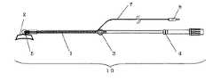
図1は、本発明の心筋温測定用具の一実施形態を示す模式図である。心筋温測定用具10は、可とう性チューブ1と、可とう性チューブ1の先端側に設けられた吸着部材2と、可とう性チューブ1の基端側に設けられた開閉部材3と、開閉部材3よりさらに基端側に設けられた逆止弁4と、を備える。そして、吸着部材2の内側には心筋温を測定できるセンサー5が設けられている。 FIG. 1 is a schematic view showing an embodiment of a myocardial temperature measuring device of the present invention. The myocardial temperature measuring device 10 includes a flexible tube 1, an
可とう性チューブ1と、吸着部材2と、開閉部材3と、逆止弁4とは連通しており、可とう性チューブ1の基端側の末端部を吸引源と接続することができる。心拍動下冠状動脈バイパス術等の心臓手術時に、1つの吸引源にて吸引を利用する別の吸引式手術用具を使用する際は、たとえば、2又に分かれたYコネクター等を介して接続することができる。 The flexible tube 1, the adsorbing
本発明の心筋温測定用具10において、可とう性チューブ1の材料は、たとえば、ポリウレタン樹脂、軟質塩化ビニル樹脂、シリコーン樹脂等の材料を用いることができる。また、可とう性チューブ1は、たとえば押出成形により形成される。可とう性チューブ1の大きさは、全長をたとえば200mm以上、好ましくは300mm以上とすることができ、内径をたとえば2mm以上、好ましくは4mm以上とすることができる。 In the myocardial temperature measuring device 10 of the present invention, the material of the flexible tube 1 may be a material such as polyurethane resin, soft vinyl chloride resin, or silicone resin. Moreover, the flexible tube 1 is formed by extrusion molding, for example. The flexible tube 1 can have a total length of, for example, 200 mm or more, preferably 300 mm or more, and an inner diameter of, for example, 2 mm or more, preferably 4 mm or more.
本発明の心筋温測定用具10において、吸着部材2は、可とう性チューブ1の先端側に設けられている。吸着部材2は、可とう性チューブ1を介して吸引源により陰圧がかけられ、吸引により、被吸着物の表面に吸着する。 In the myocardial temperature measuring device 10 of the present invention, the
ここで、被吸着物は、心臓である。このため、吸着部材2は、心臓表面に対する密着性に優れた材料とすることが好ましい。吸着部材2の材料は、たとえば弾性体とすることができる。こうすることにより、心臓表面に充分にフィットさせ、密着性を確保することができる。弾性体として、たとえば、シリコーン樹脂、スチレン−エチレン−ブタジエン−スチレン樹脂、ウレタンエラストマー等のエラストマーとすることができる。また、吸着部材2の材料はたとえば、ポリカーボネート樹脂や硬質塩化ビニル樹脂などの硬質プラスチックにしてもよい。こうすることで心臓の拍動を抑制することができ好ましい。この場合は、心臓表面に対する密着性を向上させるため、吸着面には前述の弾性体を付与することが好ましい。 Here, the object to be adsorbed is a heart. For this reason, the
また、吸着部材2の形状は、図2および図3に示すように、平面がほぼ楕円形のカップ状とすることができる。こうすることにより、心臓表面の血管を吸引、損傷することなく最大の接触面積で心臓表面に吸着させることができ、後述する心筋温測定用センサーの先端と心臓表面との接触を良好にし、正確な心筋温度を測定できる。 Further, as shown in FIGS. 2 and 3, the shape of the adsorbing
また、吸着部材2の長さは、たとえば20mm以上60mm以下、好ましくは30mm以上50mm以下である。吸着部材2の長さを上記範囲とすることで吸着部材2を心臓表面にさらに安定的に吸着することができると共に、作業性をさらに向上させることができる。さらに、吸着部材2の幅は、たとえば5mm以上30mm以下、好ましくは10mm以上20mm以下である。吸着部材2の幅を上記範囲とすることで心臓表面にさらに安定的に吸着でき、作業性を向上させることができる。さらに、吸着部材2の高さは、たとえば5mm以上30mm以下とすることが好ましい。こうすることにより作業性を向上させることができる。 Further, the length of the adsorbing
また、吸着部材2は、図2に示すように、内側に開口部6を有する。開口部6は可とう性チューブ1に連通している構成とすることができる。また、吸着部材2の開口部6を覆う複数の小さな孔が開いたメッシュ等を付設してもよい。このとき、心臓の表面は、メッシュを介して吸着部材2に接する構成となる。 Moreover, the adsorption |
また、たとえば、開口部6の周囲に凸部を設け、吸引開口部との間に隙間を設けるようにメッシュ等を付設してもよい。こうすることにより、吸引面積の減少を防止することができる。よって、吸着部材2における吸引力を向上させることができる。メッシュ等の材質は、ポリエチレンテレフタレート等のポリエステル繊維や、ナイロン等のポリアミド繊維や、吸水性効果を有する不織布やコットンとすることができる。 Further, for example, a convex portion may be provided around the opening 6 and a mesh or the like may be provided so as to provide a gap between the suction opening. By doing so, it is possible to prevent a reduction in suction area. Therefore, the suction force in the
また、吸着部材2の内側の側面には、複数の凹状スリットが形成されていることが好ましい。吸着部材2に、可とう性チューブ1に連通する連通口と、吸着部材2の端部から連通口に向かって延びる複数のスリット状の凹部と、をさらに設けることができる。スリットは、吸着部材2の内側の側面に形成された溝部である。スリットを設けることにより、スリットから開口部6を経由して吸着部材2内の液体を可とう性チューブ1に効率よく排出することができる。よって、吸着部材2内に液体がたまって排出経路が塞がれることがなく、組織表面の体液等の水切り効果を得ることができ、吸着部材2の被吸着物に対する横滑りを防止できる。また、複数のスリット状の凹部が、吸着面に略垂直方向(吸引方向)に延在するとともに互いに略平行に設けられている構成とすることができる。 Moreover, it is preferable that a plurality of concave slits are formed on the inner side surface of the
また、複数のスリットは吸着部材2の中心から周辺に向かってのびており、放射状に形成されてもよい。このため、吸着部材2の中の液体を開口部の内部から外部に向かって効率よく排出することができる。また、複数のスリットが吸着部材2の内側面の周方向に設けられていてもよい。さらに、スリットは吸着部材2の端部付近まで形成されていることが好ましい。こうすれば、上述の水切り効果に加えて、吸着部材2の端部まで確実に吸引圧をかけることができるという効果が得られる。このため、吸引効率を向上させることができる。 Further, the plurality of slits extend from the center of the
スリットの幅はたとえば0.2mm以上1mm以下、深さは0.5mm以上5mm以下とすることが好ましい。こうすることにより、被吸着物がスリット内に完全に浸入してスリットの水切り効果を損なうことを抑制できる。このため、吸着部材2の水切り効果を向上させることができる。 The width of the slit is preferably, for example, 0.2 mm to 1 mm, and the depth is preferably 0.5 mm to 5 mm. By carrying out like this, it can suppress that a to-be-adsorbed object penetrate | invades into a slit completely, and impairs the draining effect of a slit. For this reason, the draining effect of the
次に、本発明の心筋温測定用具10において、可とう性チューブ1の基端側には開閉部材3が設けられている。開閉部材3は、図1に示したようにコック3とすることができる。 Next, in the myocardial temperature measuring device 10 of the present invention, an opening / closing member 3 is provided on the proximal end side of the flexible tube 1. The opening / closing member 3 can be a cock 3 as shown in FIG.
また、たとえば、開閉部材3をコック3とする場合、たとえば、一方向に回転できないようにストッパーを設けることで二方向のみに限定して調整できる構造としてもよい。こうすれば、コック3の回転調整により、
i)吸着部材2により心臓表面を吸着する際の確実な吸引操作、および
ii)吸着部材2を心臓表面から取り外す際に、確実に吸引源から遮断しつつ、安全に大気開放する操作、を実施できる。Further, for example, when the opening / closing member 3 is a cock 3, for example, a structure that can be adjusted only in two directions by providing a stopper so as not to rotate in one direction may be adopted. In this way, by adjusting the rotation of the cock 3,
i) A reliable suction operation when adsorbing the heart surface by the adsorbing
また、開閉部材3を二方向のみに調整できる構造として、コック3のような回転させる構造の他に、たとえば、コックに該当する部材が可とう性チューブ1に対し垂直方向に摺動可能な構成とすることにより、上述したi)およびii)を実施できる構造としてもよい。 Further, as a structure in which the opening / closing member 3 can be adjusted only in two directions, in addition to a structure in which the cock 3 is rotated, for example, a structure in which a member corresponding to the cock can slide in the vertical direction with respect to the flexible tube 1 By doing so, it is possible to adopt a structure that can implement the above-described i) and ii).
次に、本発明の心筋温測定用具10において、吸着部材2の内側、すなわち心臓表面と接触する部位には心筋温測定用センサー5が突設されている。このため、吸着部材2を心臓表面に吸着させることで、心筋温測定用センサー5の先端部が心臓表面と接触し、心筋温度を測定することができる。 Next, in the myocardial temperature measuring device 10 of the present invention, a myocardial
心筋温測定用センサー5にはリード線7が付設されており、リード線7は、吸着部材2の開口部6を介して、可とう性チューブ1の内部を通り、開閉部材3の手前にて、気密性を保つように外部に延在している。心筋温測定用センサー5のリード線の末端部には、モニターと接続できるプラグ8が付設されており、モニターにより心筋温度をモニタリングすることができる。 A lead wire 7 is attached to the myocardial
心筋温測定用センサー5は、サーミスタ温度センサーとすることができ、こうすることにより、正確に心筋温度を測定することができる。 The myocardial
また、心筋温測定用センサー5は、熱電対としても良い。こうすることにより、より安価なセンサーを作成することができる。 The myocardial
吸着部材2の内側に突設される心筋温測定用センサー5において、吸着部材2の開口部6の周囲に凸部が設けられている場合、心筋温測定用センサー5は、凸部に突設することができる。また、吸着部材2に開口部6を覆うメッシュが付設される場合は、心筋温測定用センサー5をメッシュの上に突設することができる。こうすることにより、心筋温測定用センサー5を最も心臓表面の側に突設することができ、確実に心臓表面に接触させることができる。 In the myocardial
心筋温測定用センサー5の先端部は、たとえば、直径が1mm以上、5mm以下の球形状とすることができる。こうすることにより、心臓表面を損傷せず、また、吸着面積の減少による吸着部材2の吸着不良を防止することができる。また、心筋温測定用センサー5は、たとえば、直径が1mm以上、10mm以下、厚みが0.5mm以上、3mm以下の円盤形状とすることができる。こうすることにより、広範囲で心臓表面と接触することができ、より確実に心筋温度を測定することができる。 The distal end portion of the myocardial
心筋温測定用センサー5の先端部の材質は、たとえば、ニッケル、マンガン、コバルト、鉄などの酸化物を混合して焼結させたものとすることができる。こうすることにより、温度の上昇に対して抵抗が減少するサーミスタとすることができる。また、材質として、チタン酸バリウムなどを使用することができる。こうすることにより、温度の上昇に対して抵抗が増大するサーミスタとすることができる。心筋温測定用センサー5は、さらにエポキシ樹脂、またはガラスによりコーティングすることができる。こうすることで、サーミスタを保護することができる。 The material of the distal end portion of the myocardial
心筋温測定用センサー5のリード線7は、たとえば、銅線等の材質とすることができる。また、リード線の保護のため、例えば、軟質塩化ビニル樹脂等で被覆することができる。リード線7の長さは、例えば1m以上、3m以下とすることができる。こうすることで、作業性を向上させることができる。さらに、長さは、延長ケーブルと接続することで、さらに大きくすることができる。 The lead wire 7 of the myocardial
また、心筋温測定用センサー5を熱電対とする場合、たとえば、クロメル(NiおよびCrを主とした合金)とアルメル(Niを主とした合金)を材質とすることができる。こうすることにより、より安価な心筋温測定用センサー5とすることができる。 When the myocardial
次に、本発明の心筋温測定用具10において、可とう性チューブ1に付設された開閉部材3よりさらに基端側には、吸着部材2から吸引源側への方向を順方向とした逆止弁4を設けることができる。 Next, in the myocardial temperature measuring device 10 of the present invention, a check that has a forward direction from the adsorbing
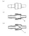
逆止弁4は、外部からの操作を加えられることなく、逆止弁4を経由する逆流を抑制できるように構成されている。つまり、逆止弁4は、流体を一方向にのみ流通させる機能を有する。具体的には、逆止弁4の基端側(吸引源の側)が吸着部材2の側に対して陰圧であるときに開状態となり、吸引圧により吸着部材2を心臓表面に吸着させる。一方、逆止弁4の基端側(吸引源の側)が吸着部材2の側に対して相対的に陽圧であるときに閉状態となるように構成される。 The check valve 4 is configured so as to be able to suppress the backflow via the check valve 4 without being subjected to an external operation. That is, the check valve 4 has a function of circulating the fluid only in one direction. Specifically, the check valve 4 is opened when the proximal end side (suction source side) is negative with respect to the
このような逆止弁4は、たとえば、吸引源側の先端で互いに接触し、閉状態となるように設けられた一対の弁体を有する。閉状態において、弁体は、可とう性チューブ1の壁面側から内部に向かって連続的に傾斜し、基端つまり吸引源側の端部で互いに接触し、密着しているため、流体の流路が遮断される。また、開状態においては、弁体の先端が離隔するため、弁体の間に流体の通路が形成される。 Such a check valve 4 has, for example, a pair of valve bodies provided so as to come into contact with each other at the tip on the suction source side and to be in a closed state. In the closed state, the valve bodies continuously incline from the wall surface side to the inside of the flexible tube 1 and are in contact with each other at the proximal end, that is, the end portion on the suction source side. The road is blocked. Further, in the open state, the tip of the valve body is separated, so that a fluid passage is formed between the valve bodies.
逆止弁4は、図4に示したようにダックビル弁とすることができる。また、図5に示すようにダックビル弁の外側には、可とう性チューブ1と接続できるようにダックビル弁を内包するハウジングを設けることができる。こうすることにより、本発明による心筋温測定用具10とは別の吸引式手術用具(たとえば、心臓の位置を調整する吸引式ポジショナーと呼ばれる用具)を、本発明による心筋温測定用具10と、1つの吸引源にて併用する際、仮に別の吸引式用具が被吸着物から外れた場合、本発明による心筋温測定用具10の吸着部材2と連通している可とう性チューブ1に付設されたダックビル弁より吸引源側の可とう性チューブ1内部にかかる吸引圧が、ダックビル弁から吸着部材2内の吸引圧より高くなる(すなわち、相対的に陽圧になる)。この差圧のため、空気の逆流が発生し、この逆流により逆止弁4が閉状態となり、心筋温測定用具10の吸着部材2内の吸引圧が保持されるため、心臓表面への吸着を維持し、確実に心筋温をモニタリングすることができる。 The check valve 4 can be a duckbill valve as shown in FIG. Moreover, as shown in FIG. 5, the housing which contains a duckbill valve can be provided in the outer side of a duckbill valve so that the flexible tube 1 can be connected. By doing so, the myocardial temperature measuring tool 10 according to the present invention is replaced with a suction type surgical tool (for example, a tool called a suction positioner for adjusting the position of the heart) different from the myocardial temperature measuring tool 10 according to the present invention. When another suction device is removed from the object to be adsorbed when used together with two suction sources, it is attached to the flexible tube 1 communicating with the adsorbing
逆止弁4の材料は、たとえば、シリコーン樹脂、アクリロニトリルゴム、イソプレンゴム、ウレタンエラストマー等のエラストマーとすることができる。また、逆止弁4は、ダックビル弁に限定せず、傘型形状等の他の逆止弁としてもよい。これらの逆止弁4は、圧縮成形等により成形することができる。また、逆止弁4を内包するハウジングの材料は、たとえば、硬質塩化ビニール樹脂、ポリカーボネート樹脂とすることができる。これらのハウジングは、射出成形等により成形することができる。ハウジングは逆止弁4を内包できるように2部品から構成することができ、2部品のハウジングは逆止弁4を内包した状態で、たとえば超音波溶着により組み立てることができる。 The check valve 4 can be made of an elastomer such as silicone resin, acrylonitrile rubber, isoprene rubber, urethane elastomer, or the like. The check valve 4 is not limited to a duckbill valve, and may be another check valve such as an umbrella shape. These check valves 4 can be formed by compression molding or the like. Moreover, the material of the housing which encloses the non-return valve 4 can be hard vinyl chloride resin and polycarbonate resin, for example. These housings can be formed by injection molding or the like. The housing can be composed of two parts so that the check valve 4 can be included, and the two-part housing can be assembled with the check valve 4 included, for example, by ultrasonic welding.
また、本発明の心筋温測定用具10において、可とう性チューブ1の先端側に設けられた吸着部材2より基端側(すなわち吸引源の側)に、開閉部材3(コック)、逆止弁4(ダックビル弁)が、この順に直列的に可とう性チューブ1に設けられた構成とすることができる。こうすることにより、逆止弁4の効果を損なうことなく、開閉部材3の操作により吸着部材2を心臓表面から取り外すための吸着部材2内部の大気開放を実施することができる。逆に言えば、開閉部材3を逆止弁4より基端側(すなわち吸引源の側)に直列的に可とう性チューブ1に設けた場合、開閉部材3の操作による吸着部材2を心臓壁から取り外すための吸着部材2内部の大気開放を実施することが逆止弁4により阻害されるため、好ましくない。 Further, in the myocardial temperature measuring device 10 of the present invention, the opening / closing member 3 (cock) and the check valve are located closer to the proximal end side (that is, the suction source side) than the
したがって、本発明の心筋温測定用具10において、可とう性チューブ1の先端側に吸着部材2を有し、かつ、可とう性チューブ1の基端側に開閉部材3を有し、吸着部材2の内側に心筋温測定用センサー5を設けることにより、心臓手術、特に心拍動下冠状動脈バイパス術において、術中の心筋温低下に伴う心臓機能の低下防止、および不整脈を防止することができ、直接的に心筋温度をモニタリングすることができる。 Therefore, in the myocardial temperature measuring device 10 of the present invention, the adsorbing
以上、本発明を実施形態に基づいて説明した。これらの実施形態はあくまで例示であり、種々の変形例が可能なこと、またそうした変形例も本発明の範囲にあることは当業者に理解されるところである。 The present invention has been described based on the embodiments. It is to be understood by those skilled in the art that these embodiments are merely examples, and that various modifications are possible and that such modifications are within the scope of the present invention.
1 可とう性チューブ
2 吸着部材
3 開閉部材(コック)
4 逆止弁(ダックビル弁)
5 心筋温測定用センサー
6 開口部
7 リード線
8 プラグ
10 心筋温度測定用処置具DESCRIPTION OF SYMBOLS 1
4 Check valve (duck bill valve)
5 Myocardial temperature measurement sensor 6 Opening 7 Lead wire 8 Plug 10 Treatment instrument for myocardial temperature measurement
Claims (4)
Translated fromJapanese前記可とう性チューブの先端側に連通して配設されて心臓を陰圧吸引する開口部、前記開口部の周囲に設けられた凸部、および前記開口部と前記凸部が形成された天蓋部を有する吸着部材と、
心筋温を測定する心筋温測定用センサー部材と、を備え、
前記心筋温測定用センサー部材は球形状または円盤形状であって前記天蓋部の開口部側の面における前記凸部の上に突設されていることを特徴とする心臓手術用心筋温測定用具。A flexible tube,
An opening that is arrangedin communication with the distal end side of the flexible tube andsucks the heart under negative pressure,a protrusion provided around the opening, and a canopyin which the opening and the protrusion are formed An adsorbing member having a portion;
It includes myocardial temperature measuring sensor member for measuringmyocardialtemperature,and
The myocardial temperature measuring device for cardiac surgery, wherein the sensor member for measuring myocardial temperature isspherical or disc-shaped and protrudes from theconvex portion on the opening side surfaceof the canopy portion.
前記心筋温測定用センサー部材が、前記凸部を覆う前記メッシュの上に突設されている請求項1に記載の心臓手術用心筋温測定用具。 The myocardial temperature measuring tool for cardiac surgery according to claim 1, wherein the sensor member for measuring myocardial temperature protrudes on the mesh covering the convex portion.
前記リード線が、前記開口部を介して前記可とう性チューブの内部を通り、かつ前記開閉部材の配設位置よりも先端側で、前記可とう性チューブの気密性を保って前記可とう性チューブの内部から外部に延在していることを特徴とする請求項1または2に記載の心臓手術用心筋温測定用具。 The lead wire passes through the inside of the flexible tube through the opening, and on the distal side of the opening / closing member, the flexible tube is kept airtight while maintaining the airtightness of the flexible tube. The myocardial temperature measuring device for cardiac surgery according to claim 1 or 2, wherein the device extends from the inside of the tube to the outside.
Priority Applications (1)
| Application Number | Priority Date | Filing Date | Title |
|---|---|---|---|
| JP2007012104AJP5004216B2 (en) | 2007-01-23 | 2007-01-23 | Myocardial temperature measuring device for cardiac surgery |
Applications Claiming Priority (1)
| Application Number | Priority Date | Filing Date | Title |
|---|---|---|---|
| JP2007012104AJP5004216B2 (en) | 2007-01-23 | 2007-01-23 | Myocardial temperature measuring device for cardiac surgery |
Publications (2)
| Publication Number | Publication Date |
|---|---|
| JP2008178432A JP2008178432A (en) | 2008-08-07 |
| JP5004216B2true JP5004216B2 (en) | 2012-08-22 |
Family
ID=39722812
Family Applications (1)
| Application Number | Title | Priority Date | Filing Date |
|---|---|---|---|
| JP2007012104AActiveJP5004216B2 (en) | 2007-01-23 | 2007-01-23 | Myocardial temperature measuring device for cardiac surgery |
Country Status (1)
| Country | Link |
|---|---|
| JP (1) | JP5004216B2 (en) |
Families Citing this family (3)
| Publication number | Priority date | Publication date | Assignee | Title |
|---|---|---|---|---|
| CN102793535B (en)* | 2012-09-12 | 2014-10-01 | 深圳市理邦精密仪器股份有限公司 | Infrared body temperature detecting device and boy temperature detecting system applying same |
| JP7375913B2 (en)* | 2020-03-19 | 2023-11-08 | 株式会社村田製作所 | Measuring device and measuring system |
| CN113654690B (en)* | 2021-07-28 | 2024-01-23 | 深圳市佳用医疗科技有限责任公司 | Thermometer for children |
Family Cites Families (6)
| Publication number | Priority date | Publication date | Assignee | Title |
|---|---|---|---|---|
| JPS5839202U (en)* | 1981-09-04 | 1983-03-15 | 安倍 十三夫 | myocardial temperature needle |
| JP3048554B2 (en)* | 1998-04-08 | 2000-06-05 | 株式会社ケーアンドエス | Local transpiration measurement capsule |
| US6231498B1 (en)* | 1999-06-23 | 2001-05-15 | Pulsion Medical Systems Ag | Combined catheter system for IABP and determination of thermodilution cardiac output |
| US6558382B2 (en)* | 2000-04-27 | 2003-05-06 | Medtronic, Inc. | Suction stabilized epicardial ablation devices |
| US6692518B2 (en)* | 2002-02-27 | 2004-02-17 | Medivance Incorporated | Patient temperature control system |
| ES2547723T3 (en)* | 2004-10-14 | 2015-10-08 | Sumitomo Bakelite Company, Limited | Treatment instrument for aortocoronary bypass surgery |
- 2007
- 2007-01-23JPJP2007012104Apatent/JP5004216B2/enactiveActive
Also Published As
| Publication number | Publication date |
|---|---|
| JP2008178432A (en) | 2008-08-07 |
Similar Documents
| Publication | Publication Date | Title |
|---|---|---|
| US11819190B2 (en) | Methods and apparatus for efficient purging | |
| JP6346625B2 (en) | Device for controlling blood outflow in the bleeding area | |
| US8417321B2 (en) | Flow reduction hood systems | |
| US6033426A (en) | Access device for surgical treatment | |
| JP4417438B2 (en) | Trocar seal system | |
| JP5301726B2 (en) | Artificial blood vessel | |
| JP2008538185A (en) | Medical device and method of use thereof | |
| WO2014162660A1 (en) | Monitoring device and monitoring device kit | |
| JP2017511720A (en) | Skin interface device with skin attachment device and method for implanting the same | |
| JP4556949B2 (en) | Coronary artery bypass surgery instrument | |
| JP5004216B2 (en) | Myocardial temperature measuring device for cardiac surgery | |
| JP2014531959A (en) | Closure device for closing open blood vessels | |
| JP2023514193A (en) | Surgical cannula with removable pressure seal | |
| JP4274073B2 (en) | Coronary artery bypass surgery instrument | |
| PT1002498E (en) | Auxiliary device for pulsatile coronary artery bypass | |
| US20090248065A1 (en) | Hemostatic device sealing damaged site with vacuum | |
| US9066653B2 (en) | Devices, systems, and methods for visualizing and manipulating tissue | |
| JP4487050B2 (en) | In-vivo medical device | |
| JP5678439B2 (en) | Attachment for preventing deaeration, overtube and overtube set equipped with the attachment | |
| JP2021515609A (en) | Tissue engaging device | |
| JP4716333B2 (en) | Coronary artery bypass surgery instrument | |
| CN211243269U (en) | Endoscope and insertion head thereof | |
| KR102775698B1 (en) | Scope of Endoscope lens cover attachment device | |
| CN212756794U (en) | Abdominal and pelvic drainage tube set | |
| JPH1085234A (en) | Surgical gown |
Legal Events
| Date | Code | Title | Description |
|---|---|---|---|
| A621 | Written request for application examination | Free format text:JAPANESE INTERMEDIATE CODE: A621 Effective date:20091112 | |
| A131 | Notification of reasons for refusal | Free format text:JAPANESE INTERMEDIATE CODE: A131 Effective date:20111115 | |
| A977 | Report on retrieval | Free format text:JAPANESE INTERMEDIATE CODE: A971007 Effective date:20111117 | |
| A521 | Request for written amendment filed | Free format text:JAPANESE INTERMEDIATE CODE: A523 Effective date:20120113 | |
| TRDD | Decision of grant or rejection written | ||
| A01 | Written decision to grant a patent or to grant a registration (utility model) | Free format text:JAPANESE INTERMEDIATE CODE: A01 Effective date:20120515 | |
| A01 | Written decision to grant a patent or to grant a registration (utility model) | Free format text:JAPANESE INTERMEDIATE CODE: A01 | |
| A61 | First payment of annual fees (during grant procedure) | Free format text:JAPANESE INTERMEDIATE CODE: A61 Effective date:20120517 | |
| FPAY | Renewal fee payment (event date is renewal date of database) | Free format text:PAYMENT UNTIL: 20150601 Year of fee payment:3 | |
| R150 | Certificate of patent or registration of utility model | Ref document number:5004216 Country of ref document:JP Free format text:JAPANESE INTERMEDIATE CODE: R150 Free format text:JAPANESE INTERMEDIATE CODE: R150 | |
| R250 | Receipt of annual fees | Free format text:JAPANESE INTERMEDIATE CODE: R250 | |
| R250 | Receipt of annual fees | Free format text:JAPANESE INTERMEDIATE CODE: R250 | |
| R250 | Receipt of annual fees | Free format text:JAPANESE INTERMEDIATE CODE: R250 | |
| R250 | Receipt of annual fees | Free format text:JAPANESE INTERMEDIATE CODE: R250 | |
| R250 | Receipt of annual fees | Free format text:JAPANESE INTERMEDIATE CODE: R250 | |
| R250 | Receipt of annual fees | Free format text:JAPANESE INTERMEDIATE CODE: R250 | |
| R250 | Receipt of annual fees | Free format text:JAPANESE INTERMEDIATE CODE: R250 | |
| R250 | Receipt of annual fees | Free format text:JAPANESE INTERMEDIATE CODE: R250 | |
| R250 | Receipt of annual fees | Free format text:JAPANESE INTERMEDIATE CODE: R250 | |
| R250 | Receipt of annual fees | Free format text:JAPANESE INTERMEDIATE CODE: R250 |