JP5002515B2 - Multi-function display - Google Patents
Multi-function displayDownload PDFInfo
- Publication number
- JP5002515B2 JP5002515B2JP2008095438AJP2008095438AJP5002515B2JP 5002515 B2JP5002515 B2JP 5002515B2JP 2008095438 AJP2008095438 AJP 2008095438AJP 2008095438 AJP2008095438 AJP 2008095438AJP 5002515 B2JP5002515 B2JP 5002515B2
- Authority
- JP
- Japan
- Prior art keywords
- storage medium
- external storage
- image data
- information
- vehicle body
- Prior art date
- Legal status (The legal status is an assumption and is not a legal conclusion. Google has not performed a legal analysis and makes no representation as to the accuracy of the status listed.)
- Expired - Fee Related
Links
- 238000012545processingMethods0.000claimsdescription81
- 238000000034methodMethods0.000claimsdescription79
- 238000001514detection methodMethods0.000claimsdescription17
- 230000006870functionEffects0.000description66
- 238000003745diagnosisMethods0.000description51
- 238000012423maintenanceMethods0.000description44
- 238000012544monitoring processMethods0.000description35
- 238000013500data storageMethods0.000description15
- 239000000446fuelSubstances0.000description10
- 239000010720hydraulic oilSubstances0.000description8
- 238000004891communicationMethods0.000description6
- 238000003825pressingMethods0.000description6
- 239000000498cooling waterSubstances0.000description5
- 230000012447hatchingEffects0.000description4
- 239000010705motor oilSubstances0.000description4
- 238000004321preservationMethods0.000description4
- 238000004364calculation methodMethods0.000description3
- 239000002826coolantSubstances0.000description3
- 238000010586diagramMethods0.000description3
- 239000004973liquid crystal related substanceSubstances0.000description3
- 238000007726management methodMethods0.000description3
- 239000003921oilSubstances0.000description3
- 230000000694effectsEffects0.000description2
- 230000005540biological transmissionEffects0.000description1
- 238000010276constructionMethods0.000description1
- 238000002347injectionMethods0.000description1
- 239000007924injectionSubstances0.000description1
Images


Classifications
- E—FIXED CONSTRUCTIONS
- E02—HYDRAULIC ENGINEERING; FOUNDATIONS; SOIL SHIFTING
- E02F—DREDGING; SOIL-SHIFTING
- E02F9/00—Component parts of dredgers or soil-shifting machines, not restricted to one of the kinds covered by groups E02F3/00 - E02F7/00
- E02F9/26—Indicating devices
- E—FIXED CONSTRUCTIONS
- E02—HYDRAULIC ENGINEERING; FOUNDATIONS; SOIL SHIFTING
- E02F—DREDGING; SOIL-SHIFTING
- E02F9/00—Component parts of dredgers or soil-shifting machines, not restricted to one of the kinds covered by groups E02F3/00 - E02F7/00
- E02F9/20—Drives; Control devices
- E02F9/2025—Particular purposes of control systems not otherwise provided for
- B—PERFORMING OPERATIONS; TRANSPORTING
- B60—VEHICLES IN GENERAL
- B60Y—INDEXING SCHEME RELATING TO ASPECTS CROSS-CUTTING VEHICLE TECHNOLOGY
- B60Y2200/00—Type of vehicle
- B60Y2200/40—Special vehicles
- B60Y2200/41—Construction vehicles, e.g. graders, excavators
- B60Y2200/412—Excavators
- G—PHYSICS
- G09—EDUCATION; CRYPTOGRAPHY; DISPLAY; ADVERTISING; SEALS
- G09G—ARRANGEMENTS OR CIRCUITS FOR CONTROL OF INDICATING DEVICES USING STATIC MEANS TO PRESENT VARIABLE INFORMATION
- G09G3/00—Control arrangements or circuits, of interest only in connection with visual indicators other than cathode-ray tubes
- G09G3/20—Control arrangements or circuits, of interest only in connection with visual indicators other than cathode-ray tubes for presentation of an assembly of a number of characters, e.g. a page, by composing the assembly by combination of individual elements arranged in a matrix no fixed position being assigned to or needed to be assigned to the individual characters or partial characters
Landscapes
- Engineering & Computer Science (AREA)
- Mining & Mineral Resources (AREA)
- Civil Engineering (AREA)
- General Engineering & Computer Science (AREA)
- Structural Engineering (AREA)
- Component Parts Of Construction Machinery (AREA)
- Controls And Circuits For Display Device (AREA)
- Control Of Indicators Other Than Cathode Ray Tubes (AREA)
Description
Translated fromJapanese本発明は油圧ショベル等の作業機に搭載される多機能表示装置に係わり、特に作業機の車体基本情報を表示する機能を有するとともに、車体基本情報より使用頻度が低い情報を表示する機能や、その他の処理機能を有する多機能表示装置に関する。 The present invention relates to a multi-function display device mounted on a work machine such as a hydraulic excavator, and in particular has a function of displaying vehicle body basic information of the work machine, a function of displaying information that is less frequently used than vehicle body basic information, The present invention relates to a multi-function display device having other processing functions.
近年、油圧ショベル等の作業機の電子制御化が進み、それに伴って作業機に搭載される表示装置も進化し、液晶モニタを搭載して詳細な情報を表示するなど、高機能化が進んでいる。高機能化の中には、燃料残量、冷却水温等の車体の基本情報を表示させるだけでなく、故障診断機能等の各種情報を表示させる多機能化が含まれる(特許文献1及び2)。 In recent years, electronic control of work machines such as hydraulic excavators has progressed, and along with this, display devices mounted on work machines have also evolved, and advanced functions have been developed, such as displaying detailed information with a liquid crystal monitor. Yes. The enhancement of functions includes not only basic information of the vehicle body such as the remaining fuel amount and cooling water temperature, but also multi-functionality that displays various information such as a failure diagnosis function (
一方、制御装置に多様な機能を発揮させようとした場合、制御装置に多数の制御プログラムを格納しておく結果、記憶装置のメモリ量が増え、動作速度が遅くなるなどの不具合を生じる。特許文献3ではそのような不具合を解消するために、携帯可能な外部記憶装置に常時使用することのない検査プログラム、故障診断プログラム等の制御プログラムの一部を記憶しておき、必要に応じてその外部記憶装置を制御装置に装着し、外部記憶装置内の制御プログラムを読み出して制御装置で使用することが提案されている。 On the other hand, when trying to exhibit various functions in the control device, as a result of storing a large number of control programs in the control device, the amount of memory in the storage device increases, resulting in problems such as a decrease in operating speed. In
しかしながら、上記従来技術には次のような課題がある。 However, the above prior art has the following problems.
表示装置を多機能化した場合、機能の数に応じた制御プログラムが必要となるだけでなく、これらの制御プログラム(機能)を実行するための画像データ(情報を表示するための画像データやユーザインターフェースを表示するための画像データ)が必要となる。データ量が多いのは制御プログラムよりもむしろ画像データである。 When a display device is multi-functionalized, not only a control program corresponding to the number of functions is required, but also image data for executing these control programs (functions) (image data for displaying information or a user) Image data for displaying the interface) is required. A large amount of data is image data rather than a control program.
特許文献1,2において明記はないが、画像データは、一般に表示装置の記憶装置に格納されている。しかし、表示装置を多機能化に応じて全ての画像データを表示装置の記憶部に記憶させると、そのデータ量の増加に対応するために記憶装置を大容量化することが必要となる。記憶装置の大容量化はコストが嵩む。 Although not specified in
特許文献3では、携帯可能な外部記憶装置に制御プログラムが記憶されているだけであり、画像データの増加には対応することができない。 In
本発明の目的は、表示装置が持つ記憶装置の限られた容量の中で表示装置の多機能化に対応して各種画像データを表示することができる多機能表示装置を提供することである。 An object of the present invention is to provide a multi-function display device capable of displaying various image data corresponding to the multi-function of the display device within the limited capacity of the storage device of the display device.
(1)上記目的を達成するために、本発明は、作業機に搭載される多機能表示装置において、作業機の車体基本情報を表示するための第1画像データを記憶する第1記憶装置と、第1画像データを用いて作業機の車体基本情報を表示する第1表示制御装置と、表示切替手段と、外部記憶媒体が着脱自在に装着される外部記憶媒体装着部と、前記外部記憶媒体装着部に前記外部記憶媒体が装着され、前記表示切替手段が動作したときに、少なくとも、前記外部記憶媒体から読み込んだ第2画像データを用いて前記車体基本情報より使用頻度が低い情報を表示する第2表示制御装置とを備え、前記外部記憶媒体装着部に前記外部記憶媒体が装着されたかどうかを検出し、前記外部記憶媒体装着部に前記外部記憶媒体が装着されたことが検出されると、前記外部記憶媒体から読み込んだ第2画像データを消去可能な第2記憶装置に記憶させる外部記憶媒体接続検出処理装置を更に備え、前記第2表示制御装置は、前記第2記憶装置に記憶した第2画像データを用いて前記車体基本情報より使用頻度が低い情報を表示するものとする。(1) In order to achieve the above object, the present invention provides a first storage device for storing first image data for displaying vehicle body basic information of a work implement in a multi-function display device mounted on the work implement. First display control device for displaying vehicle body basic information of work implement using first image data, display switching means, external storage medium mounting portion to which external storage medium is detachably mounted, and external storage medium When the external storage medium is attached to the attachment portion and the display switching unit is operated, at least information that is less frequently used than the vehicle body basic information is displayed using the second image data read from the external storage medium. and a second display controlunit, to detect whether said external storage medium to the external storage medium mounting unit is mounted, the external storage medium is detected to have been attached to the external storage medium mounting unit And an external storage medium connection detection processing device for storing the second image data read from the external storage medium in an erasable second storage device, wherein the second display control device stores the second image data in the second storage device Information that is used less frequently than the vehicle body basic information is displayed using the second image data.
このように第1表示制御装置とは別に第2表示制御装置を設け、車体基本情報より使用頻度が低い情報に対しては、第2表示制御装置が外部記憶媒体から読み込んだ第2画像データを用いて表示することにより、多機能表示装置が持つ記憶装置(第1記憶装置)は車体基本情報を表示するための第1画像データを記憶するだけでよくなり、記憶装置(第1記憶装置)の限られた容量の中で表示装置の多機能化に対応して各種画像データを表示することができる。
更に、外部記憶媒体接続検出処理装置が外部記憶媒体から読み込んだ第2画像データを消去可能な第2記憶装置に記憶させ、第2表示制御装置が第2記憶装置に記憶した第2画像データを用いて表示することにより、外部記憶媒体に保存した第2画像データを用いて、車体基本情報より使用頻度が低い情報を迅速に表示することができる。As described above, the second display control device is provided separately from the first display control device, and the second image data read from the external storage medium by the second display control device is used for information that is less frequently used than the vehicle body basic information. By using and displaying, the storage device (first storage device) of the multi-function display device need only store the first image data for displaying the vehicle body basic information, and the storage device (first storage device). Various image data can be displayed in accordance with the multi-functionality of the display device within the limited capacity.
Further, the second image data read from the external storage medium by the external storage medium connection detection processing device is stored in an erasable second storage device, and the second image data stored in the second storage device by the second display control device is stored. By using and displaying, information that is less frequently used than the vehicle body basic information can be quickly displayed using the second image data stored in the external storage medium.
(2)上記(1)において、好ましくは、前記第2表示制御装置は、所定の処理を行なう処理機能を含み、前記外部記憶媒体から読み込んだ前記第2画像データを用いて表示される前記車体基本情報より使用頻度が低い情報は、前記所定の処理を実行するためのユーザインターフェースを含むものとする。 (2) In the above (1), preferably, the second display control device includes a processing function for performing a predetermined process, and is displayed using the second image data read from the external storage medium. Information that is used less frequently than the basic information includes a user interface for executing the predetermined processing.
これにより記憶装置(第1記憶装置)の限られた容量の中で、バージョンアップ、ダウンロード等の各種処理を行うためのユーザインターフェースを表示し、当該処理を円滑に行うことができる。 Accordingly, a user interface for performing various processes such as version upgrade and download can be displayed in a limited capacity of the storage device (first storage device), and the processing can be performed smoothly.
(3)上記(1)において、好ましくは、前記第2表示制御装置は、前記外部記憶媒体に記憶したバージョンアップ用のプログラムをダウンロードし、前記作業機に搭載された少なくとも1つのコントローラをバージョンアップするためのバージョンアップ機能を含み、前記外部記憶媒体から読み込んだ前記第2画像データを用いて表示される前記車体基本情報より使用頻度が低い情報は、前記バージョンアップ機能を実行するためのユーザインターフェースを含むものとする。 (3) In the above (1), preferably, the second display control device downloads an upgrade program stored in the external storage medium, and upgrades at least one controller mounted on the work implement. Information having a lower frequency of use than the vehicle body basic information displayed using the second image data read from the external storage medium is included in a user interface for executing the upgrade function. Shall be included.
これにより記憶装置(第1記憶装置)の限られた容量の中で、作業機に搭載されたコントローラのバージョンアップを行うためのユーザインターフェースを表示し、当該バージョンアップを円滑に行うことができる。 Accordingly, the user interface for upgrading the controller mounted on the work machine can be displayed within the limited capacity of the storage device (first storage device), and the upgrade can be performed smoothly.
(4)上記(1)において、好ましくは、前記第2表示制御装置は、前記第2画像データを用いて前記車体基本情報より使用頻度が低い情報を表示する表示機能と、前記作業機に搭載された情報コントローラからこの情報コントローラに蓄積した車体情報を前記外部記憶媒体にダウンロードするためのダウンロード機能を含み、前記外部記憶媒体から読み込んだ前記第2画像データを用いて表示される前記車体基本情報より使用頻度が低い情報は、前記ダウンロード機能を実行するためのユーザインターフェースを含むものとする。 (4) In the above (1), preferably, the second display control device is mounted on the work machine with a display function for displaying information that is used less frequently than the vehicle body basic information using the second image data. The vehicle body basic information displayed by using the second image data read from the external storage medium, including a download function for downloading the vehicle body information stored in the information controller from the read information controller to the external storage medium Information that is used less frequently includes a user interface for executing the download function.
これにより記憶装置(第1記憶装置)の限られた容量の中で、作業機に搭載された情報コントローラから車体情報のダウンロードを行うためのユーザインターフェースを表示し、当該車体情報のダウンロードを円滑に行うことができる。 As a result, the user interface for downloading the vehicle body information from the information controller mounted on the work implement is displayed within the limited capacity of the storage device (first storage device), and the vehicle body information can be downloaded smoothly. It can be carried out.
本発明によれば、多機能表示装置が持つ記憶装置の限られた容量の中で表示装置の多機能化に対応して各種画像データを表示することができる。 According to the present invention, it is possible to display various image data corresponding to the multi-function of the display device within the limited capacity of the storage device of the multi-function display device.
また、記憶装置(第1記憶装置)の限られた容量の中で、バージョンアップ、ダウンロード等の各種処理を行うためのユーザインターフェースを表示し、当該処理を円滑に行うことができる。 In addition, it is possible to display a user interface for performing various processes such as version upgrade and download within the limited capacity of the storage device (first storage device), and to perform the processing smoothly.
更に、外部記憶媒体に保存した第2画像データを用いて車体基本情報より使用頻度が低い情報を迅速に表示することができる。Furthermore, it is possible to use from the vehicle body basic information often displaysa low informationquickly using the second image data stored in the external storage medium.
以下、本発明の実施の形態を図面に従い説明する。 Hereinafter, embodiments of the present invention will be described with reference to the drawings.
〜構成〜
図1は、本発明の一実施の形態に係わる多機能表示装置を備えた制御システムの全体構成を示す図である。~Constitution~
FIG. 1 is a diagram showing an overall configuration of a control system including a multifunctiondisplay device according to an embodiment of the present invention.
図1において、本実施の形態に係わる制御システムは、多機能表示装置20と、車体コントローラ51と、エンジンコントローラ52と、情報コントローラ53とを有し、これらは車体ネットワーク50を介して相互に接続されている。また本実施の形態は、本発明を建設機械の代表例である油圧ショベル(作業機)に適用した場合のものであり、多機能表示装置20、車体コントローラ51、エンジンコントローラ52、情報コントローラ53は油圧ショベルに搭載されている(後述)。車体コントローラ51は油圧ショベルの油圧駆動装置15を電子制御するものであり、エンジンコントローラ52はエンジン16に備えられる電子ガバナを制御することで、エンジン16に供給される燃料の噴射量を制御しエンジン回転数と出力トルクを制御するものである。油圧駆動装置15はエンジン16により回転駆動される油圧ポンプと、この油圧ポンプから吐出された圧油により駆動され、フロント作業機等の被駆動体を駆動する複数の油圧アクチュエータと、油圧ポンプから油圧アクチュエータに供給される圧油の流れを制御するコントロールバルブと、このコントロールバルブを操作し対応する油圧アクチュエータを駆動する操作レバー装置等の油圧機器を含んでいる。車体コントローラ51は、例えば、操作レバー装置の操作量を検出し、その操作量に応じた流量を吐出するように油圧ポンプの傾転角(容量)を制御する。 In FIG. 1, the control system according to the present embodiment includes a
多機能表示装置20は、エンジン16に供給する燃料の残量を検出する燃料残量センサ41、エンジン16の冷却水温度を検出する冷却水温センサ42、油圧駆動装置15の作動油の油温を検出する作動油温センサ43の検出値を入力し、それらセンサの検出値や、車体コントローラ51及びエンジンコントローラ52から車体ネットワーク50を介して送信されるその他の車体データを車体基本情報として表示する(後述)。情報コントローラ53は、多機能表示装置20、車体コントローラ51、エンジンコントローラ52から車体ネットワーク50を介して燃料残量センサ41、冷却水温センサ42、作動油温センサ43の検出値やその他の車体データを含む各種データを入力し、それらをデータベースに収集(保存)、蓄積する。また、情報コントローラ53は、所定の時間間隔で(例えば1日に1回)、その蓄積した稼動データを例えば管理会社のサーバーへ通信装置64を介して無線で送信する。 The
多機能表示装置20は、上述した油圧ショベルの車体基本情報を表示する機能と、車体基本情報より使用頻度が低い情報を表示しかつ所定の処理を行う機能とを有している。以下に多機能表示装置20の機能の詳細を説明する。 The
多機能表示装置20は、入力インターフェース21と、外部記憶媒体装着部22と、外部記憶媒体インターフェース23と、通信部24と、プログラム記憶部(第1ROM)25と、画像記憶部(第2ROM)26と、RAM27と、CPU28と、画像制御部31と、表示部32とを有している。 The
入力インターフェース21は、燃料残量センサ41、冷却水温センサ42及び作動油温センサ43の検出値を検出信号としてそれぞれ入力するとともに、多機能表示装置20が備える操作キースイッチ部44(後述)からの操作信号を入力する。 The
外部記憶媒体装着部22は、外部記憶媒体45を着脱自在に装着するものであり、外部記憶媒体インターフェース23は、外部記憶媒体装着部22に外部記憶媒体45が装着されたかどうかを検出するとともに、外部記憶媒体45からのデータの入力及び外部記憶媒体45へのデータの出力を行なう。外部記憶媒体45は例えばUSBメモリである。通信部24は車体ネットワーク50に対するデータの入出力を行なう。 The external storage medium attachment unit 22 is detachably attached to the external storage medium 45, and the external
プログラム記憶部(第1ROM)25は、CPU28の演算で用いる所定のプログラムを記憶しており、画像記憶部(第2ROM)26は、車体基本情報を表示するための画像データ(第1画像データ)を記憶している。RAM27は、演算途中のデータや外部記憶媒体インターフェース23を介して外部記憶媒体45から読み込んだ、車体基本情報より使用頻度が低い情報を表示するための画像データ(第2画像データ)を一時的に記憶する。 The program storage unit (first ROM) 25 stores a predetermined program used in the calculation of the
CPU28は、入力インターフェース21、外部記憶媒体インターフェース23、通信部24、画像記憶部26、RAM27からデータを入力し、プログラム記憶部25に記憶されたプログラムに基づいて所定の演算処理を行なう。 The
画像制御部31は、CPU28の演算結果に基づいて表示データを表示部32に出力し、表示部32に所定の情報を表示する。表示部32は、たとえば液晶表示パネルにより構成されている。 The image control unit 31 outputs display data to the
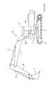
図2は、本発明の一実施の形態に係わる多機能表示装置20を備えた制御システムが搭載される油圧ショベルの外観を示す図である。 FIG. 2 is a diagram showing an external appearance of a hydraulic excavator on which a control system including the
図2において、油圧ショベルは、走行体1と、この走行体1上に旋回装置3を介して旋回可能に搭載された旋回体2と、この旋回体2の前部中央に俯仰動可能に設けられたフロント作業機6を備え、フロント作業機6はブーム7、アーム8、バケット9から構成されている。走行体1は左右の走行モータ13a,13bにより駆動され、旋回体2は旋回装置3に内蔵された旋回モータ14により駆動され、ブーム7、アーム8、バケット9は、ブームシリンダ10、アームシリンダ11、バケットシリンダ12によりそれぞれ駆動される。走行モータ13a,13b、旋回モータ14、ブームシリンダ10、アームシリンダ11、バケットシリンダ12は上述した油圧駆動装置15の複数のアクチュエータを構成する。 In FIG. 2, the hydraulic excavator includes a traveling
旋回体2上にはキャビン5が搭載され、キャビン5内の運転室には上述した多機能表示装置20や操作レバー装置が配置されている。 A
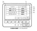
図3は多機能表示装置20の表示部32を含む表示操作部分を示す図である。多機能表示装置20の表示操作部分は表示部32と操作キースイッチ部44を有している。表示部32は液晶等の表示パネルにより構成されており、図示の例では通常画面100(後述)が表示されている。操作キースイッチ部44は表示部32の下側に配置され、F1からF7の複数のファンクションキー44a〜gと、メニューキー44h及びバックモニタキー44iとから構成されている。 FIG. 3 is a diagram illustrating a display operation portion including the
次に、多機能表示装置20のCPU28の演算処理内容を説明する。CPU28は、図1に示すように、外部記憶媒体接続検出処理部29としての処理機能と、表示制御処理部30としての処理機能を有している。本発明においては、これらの処理機能を実行するためのプログラムはプログラム記憶部25に記憶されており、表示部32に表示される画像のデータは画像記憶部26と外部記憶媒体45に分けて記憶されている。プログラム記憶部25に記憶された表示制御処理部30としての処理機能を行うためのプログラムは、それらの画像データ(画像記憶部26と外部記憶媒体45に記憶された画像データ)を表示するためのプログラムと、所定の処理(例えばバージョンアップ、ダウンロード等)を実行するためのプログラムを含むものである。以下に、それらの詳細を図4〜図23を用いて説明する。 Next, the contents of arithmetic processing of the
図4はCPU28の外部記憶媒体接続検出処理部29としての処理機能を示すフローチャートである。 FIG. 4 is a flowchart showing processing functions of the
前述したように、外部記憶媒体インターフェース23は外部記憶媒体装着部22に外部記憶媒体45が装着されたどうかを検出しており、CPU28はその検出結果を入力し、外部記憶媒体装着部22に外部記憶媒体45が装着されたかどうかを判定する(ステップS11)。判定結果がNoの場合は、その処理を繰り返す。判定結果がYesになると、モニタリング画像データ保存処理(ステップS20)、故障診断画像データ保存処理(ステップS30)、バージョンアップ画像データ保存処理(ステップS40)、ダウンロード画像データ保存処理(ステップS50)を実行する。 As described above, the external
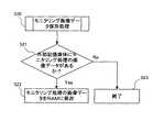
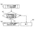
図5は、モニタリング画像データ保存処理(ステップS20)の詳細を示すフローチャートであり、図6は、故障診断画像データ保存処理(ステップS30)の詳細を示すフローチャートであり、図7は、バージョンアップ画像データ保存処理(ステップS40)の詳細を示すフローチャートであり、図8は、ダウンロード画像データ保存処理(ステップS50)の詳細を示すフローチャートである。 FIG. 5 is a flowchart showing details of the monitoring image data saving process (step S20), FIG. 6 is a flowchart showing details of the failure diagnosis image data saving process (step S30), and FIG. 7 is a version-up image. FIG. 8 is a flowchart showing details of the data storage process (step S40), and FIG. 8 is a flowchart showing details of the download image data storage process (step S50).
図5に示すモニタリング画像データ保存処理において、CPU28は、外部記憶媒体インターフェース23を介して外部記憶媒体45にアクセスし、外部記憶媒体45にモニタリング処理の画像データが保存されているかどうかを判断し(ステップS21)、判定結果がYesの場合は、モニタリング処理の画像データを外部記憶媒体45から読み出し、RAM27に一時的に保存させる(ステップS22)。判定結果がNoの場合は、処理を終了する(ステップS23)。 In the monitoring image data saving process shown in FIG. 5, the
図6に示す故障診断画像データ保存処理において、CPU28は、外部記憶媒体インターフェース23を介して外部記憶媒体45にアクセスし、外部記憶媒体45に故障診断処理の画像データが保存されているかどうかを判断し(ステップS31)、判定結果がYesの場合は、故障診断処理の画像データを外部記憶媒体45から読み出し、RAM27に一時的に保存させる(ステップS32)。判定結果がNoの場合は、処理を終了する(ステップS33)。 In the failure diagnosis image data saving process shown in FIG. 6, the
図7に示すバージョンアップ画像データ保存処理において、CPU28は、外部記憶媒体インターフェース23を介して外部記憶媒体45にアクセスし、外部記憶媒体45にバージョンアップしたプログラム(各コントローラの最新バージョンの制御プログラム)があるかどうかを判断し(ステップS41)、判定結果がYesの場合は、車体ネットワーク50を介して対象コントローラの制御プログラムのバージョン情報を入力し(ステップS42)、これを外部記憶媒体45内のバージョンアップのプログラムのバージョン情報と比較し、バージョンアップ処理が必要なコントローラがあるかどうかを判断し(ステップS43)、判定結果がYesの場合は、バージョンアップ処理の画像データを外部記憶媒体45から読み出し、RAM27に一時的に保存させる(ステップS44)。ステップS41またはステップS43の判定結果がNoの場合は、処理を終了する(ステップS45)。 In the upgraded image data saving process shown in FIG. 7, the
図8に示すダウンロード画像データ保存処理において、CPU28は、外部記憶媒体インターフェース23を介して外部記憶媒体45にアクセスし、外部記憶媒体45にダウンロード処理に必要な空き容量があるかどうかを判断し(ステップS51)、判定結果がYesの場合は、ダウンロード処理の画像データを外部記憶媒体45から読み出し、RAM27に一時的に保存させる(ステップS52)。判定結果がNoの場合は、処理を終了する(ステップS53)。 In the download image data storage process shown in FIG. 8, the
図9はCPU28の表示制御処理部30としての処理機能を示すフローチャートである。CPU28は、まず画像記憶部26の画像データを用い、初期画面として図3に示す通常画面100を表示部32に表示する(ステップS61)。次いで、メニューキー44hが押されたかどうか(ONかどうか)を判断し(ステップS62)、判定結果がNoで、メニューキー44hが押されていない場合は、その処理を繰り返す。判定結果がYesになると、更に、RAM27に外部記憶媒体45から読み出された画像データが保存されているかどうかを判断し(ステップS63)、判定結果がNoでRAM27に外部記憶媒体45から読み出された画像データが保存されていない場合は、画像記憶部26に記憶された画像データを用い、表示部32の画面を通常画面100から図10に示すメニュー画面表示1の画面110に切り替え(ステップS64)、判定結果がYesの場合は、例えば図11に示すようなメニュー画面表示2の画面120に切り替る(ステップS65)。Figure 9 is a flow chart showing the processing function of the display
図10の画面110では、メンテナンスメニューの項目111aのみが表示され、その項目111aに網掛けハッチングで示すカーソルKが表示される。図11のメニュー画面表示2の画面120は、図5〜図8に示すモニタリング画像データ保存処理、故障診断画像データ保存処理、バージョンアップ画像データ保存処理、ダウンロード画像データ保存処理における判定が全て肯定された場合(外部記憶媒体45にモニタリング処理の画像データ、故障診断処理の画像データ、バージョンアップしたプログラムが保存されており、かつ制御システムにバージョンアップ処理が必要なコントローラがあり、外部記憶媒体45にダウンロード処理に必要な空き容量がある場合)のものである。この画面120では、画像記憶部26に記憶された画像データを用いてメンテナンスメニューの項目121aが表示されるとともに、外部記憶媒体45から取得しRAM27に保存したモニタリング処理、故障診断処理、バージョンアップ処理、ダウンロード処理の各画像データを用いて、モニタリング、故障診断、バージョンアップ、ダウンロードの項目121b,121c,121d,121eが追加表示される。項目121bはモニタリングであり、項目121cは故障診断であり、項目121dはバージョンアップであり、項目121eはダウンロードである。メニュー画面表示2の画面120に切り替わった直後の初期画面では、メンテナンスメニューの項目121aに網掛けハッチングで示すカーソルKが表示される。なお、図5〜図8に示すモニタリング画像データ保存処理、故障診断画像データ保存処理、バージョンアップ画像データ保存処理、ダウンロード画像データ保存処理における判定の全てが肯定されない場合は、肯定された判定に係わる項目のみが画面120に表示される。 In the
次いで、CPU28はメニュー画面処理を実行する(ステップS70)。また、メニューキー44hが押されたかどうか(ONかどうか)を再度判断し(ステップS66)、判定結果がNoでメニューキー44hが押されていない場合はステップS70のメニュー画面処理を繰り返し、判定結果がYesになると、ステップS61に戻り、表示部32の画面を通常画面100に切り替える。 Next, the
図12は、ステップS70におけるメニュー画面処理の詳細を示すフローチャートである。 FIG. 12 is a flowchart showing details of the menu screen processing in step S70.
CPU28は、メニュー項目としてメンテナンスメニューの項目111a(図10)又は121a(図11)が選択されたかどうかを判断する(ステップS71)。メンテナンスメニューの項目111a又は121aが選択されたかどうかは、図10及び図11に示すメニュー画面110,120において、カーソルKがメンテナンスメニューの項目111a又は121aに表示されている状態で「決定」のファンクションキー44fが押されたかどうかにより判断する。判定結果がYesの場合はメンテナンスメニュー処理に移行し(ステップS80)、判定結果がNoの場合は、更に、メニュー画面110,120にメンテナンスメニュー項目111a,121a以外の項目があるかどうかを判断する(ステップS72)。この判断は、現在、表示部32に表示されている画面が、メニュー画面表示1の画面110かメニュー画面表示2の画面120のいずれであるかを判断するものであり、この判断は、RAM27にモニタリング処理、故障診断処理、バージョンアップ処理、ダウンロード処理の各画像データが保存されているかどうかをチェックすることにより行う。そして、判定結果がNoの場合は、メンテナンスメニューの項目111aのみを有するメニュー画面表示1の画面110が表示されている場合であり、この場合は、ステップS71の処理を繰り返す。判定結果がYesの場合は、メンテナンスメニューの項目121a以外の項目121b〜eを含むメニュー画面表示2の画面120が表示されている場合であり、この場合は更に、モニタリングの項目が選択されたかどうかを判断する(ステップS73)。 The
ここで、メニュー画面表示2の画面120において、カーソルKは「下」のファンクションキー44eを押すことにより下方に動かすことができ、「上」のファンクションキー44dを押すことにより上方に動かすことができる。CPU28は、カーソルKがモニタリングの項目121bに動かされ、この状態で「決定」のファンクションキー44fが押されると、モニタリングの項目121bが選択されたと判断する。Here, on the
そして、ステップS73の判定結果がYesの場合はモニタリング処理に移行し(ステップS90)、判定結果がNoの場合は、更に、故障診断の項目121cが選択されたかどうか(ステップS74)、バージョンアップの項目121dが選択されたかどうか(ステップS75)、ダウンロードの項目121eが選択されたかどうか(ステップS76)を順次判定し、それらの判定結果がYesの場合は、故障診断処理(ステップS100)、バージョンアップ処理(ステップS110)、ダウンロード処理(ステップS120)に移行する。なお、これらの判定処理においても、CPU28は、カーソルKが項目121c,121d,121eに動かされ、この状態で「決定」のファンクションキー44fが押されると、それぞれの項目が選択されたと判断する。ステップS76の判定結果がNoの場合は、ステップS71の判断に戻る。If the determination result in step S73 is Yes, the process proceeds to a monitoring process (step S90). If the determination result is No, whether or not the failure diagnosis item121c is further selected (step S74), the version upgrade is performed. It is sequentially determined whether or not the item121d is selected (step S75) and whether or not the download item121e is selected (step S76). If the determination result is Yes, the failure diagnosis process (step S100), version upgrade is performed. The process proceeds to processing (step S110) and download processing (step S120). Also in these decision processes,
図13は、ステップS80のメンテナンスメニュー処理の詳細を示すフローチャートであり、図14は、ステップS90のモニタリング処理の詳細を示すフローチャートであり、図15は、ステップS100の故障診断処理の詳細を示すフローチャートであり、図16は、ステップS110のバージョンアップ処理の詳細を示すフローチャートであり、図17は、ステップS120のダウンロード処理の詳細を示すフローチャートである。 FIG. 13 is a flowchart showing details of the maintenance menu process in step S80, FIG. 14 is a flowchart showing details of the monitoring process in step S90, and FIG. 15 is a flowchart showing details of the failure diagnosis process in step S100. FIG. 16 is a flowchart showing details of the upgrade process in step S110, and FIG. 17 is a flowchart showing details of the download process in step S120.
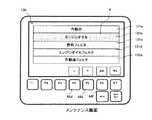
図13に示すメンテナンスメニュー処理では、CPU28は、画像記憶部26の画像データを用い、図18に示すメンテナンス項目画面130を表示部32に表示する(ステップS81)。図18のメンテナンス項目画面130では、メンテナンス項目131a〜eが表示される。メンテナンス項目131aは作動油であり、メンテナンス項目131bはエンジンオイルであり、メンテナンス項目131cは燃料フィルタであり、メンテナンス項目131dはエンジンオイルフィルタであり、メンテナンス項目131eは作動油フィルタである。次いで、メンテナンス項目131a〜eのいずれかが選択されると、例えば図19に示すようなメンテナンス詳細画面140を表示部32に表示する(ステップS82)。図19に示すメンテナンス詳細画面140はエンジンオイルのメンテナンス項目131bが選択された場合のものであり、選択された項目(エンジンオイル)のメンテナンス情報の詳細が表示される。メンテナンス項目131a〜eの選択は、前述のメニュー画面表示2の画面120の場合と同様、ファンクションキー44d〜fを操作することにより行うことができる。 In the maintenance menu process shown in FIG. 13, the
図14に示すモニタリング処理では、CPU28は、外部記憶媒体45から取得しRAM27に保存したモニタリング処理の画像データを用い、図20に示すモニタリング画面150を表示部32に表示する(ステップS91)。図20のモニタリング画面150では、モニタリング項目151a〜dとともにモニタリングの状態が表示される。モニタリング項目151aはエンジン回転数であり、モニタリング項目151bはエンジン目標回転数であり、モニタリング項目151cは燃料温度であり、モニタリング項目151dは冷却水温度である。 In the monitoring process shown in FIG. 14, the
図15に示す故障診断処理では、CPU28は、外部記憶媒体45から取得しRAM27に保存した故障診断処理の画像データを用い、図21に示す故障診断項目画面160を表示部32に表示する(ステップS101)。図21の故障診断項目画面160では、故障診断対象コントローラ項目161a〜dと、故障の有無(結果)を表示する。故障診断対象コントローラ項目161aは車体コントローラ51であり、故障診断対象コントローラ項目161bは情報コントローラ53であり、故障診断対象コントローラ項目161cはエンジンコントローラ52であり、故障診断対象コントローラ項目161dはモニタコントローラ(多機能表示装置)20である。図示の例ではエンジンコントローラ52の故障診断対象コントローラ項目161cに「故障あり」と表示され、エンジンコントローラ52に故障があることを示している。次いでオペレータは「故障あり」と表示された故障診断対象コントローラ項目を選択し、故障診断を開始する(ステップS102)。図21に示す例では、「結果」の欄に網掛けハッチングで示すカーソルKが表示されており、この状態で「決定」のファンクションキー44fを押すと、外部記憶媒体45から取得しRAM27に保存した故障診断処理の画像データを用いて例えば図22に示すような故障診断結果画面170を表示部32に表示する(ステップS103)。図22に示す故障診断結果画面170ではエンジンコントローラ52の回転センサに故障があることを示している。なお、故障診断自体は各コントローラで行なわれ、故障診断の結果情報が車体ネットワーク50を介して多機能表示装置20に送信され、多機能表示装置20のCPU28はその情報をRAM27に保存している。In the failure diagnosis process shown in FIG. 15, the
図16に示すバージョンアップ処理では、CPU28は、外部記憶媒体45から取得しRAM27に保存したバージョンアップ処理の画像データを用い、図23に示すようなバージョンアップ項目画面180を表示部32に表示する(ステップS111)。図23のバージョンアップ項目画面180では、各コントローラのバージョンアップ項目181a〜dと、バージョンアップの必要の有無を表示する。バージョンアップ項目181aは車体コントローラ51であり、バージョンアップ項目181bは情報コントローラ53であり、バージョンアップ項目181cはエンジンコントローラ52であり、バージョンアップ項目181dはモニタコントローラ(多機能表示装置)20である。図示の例では情報コントローラ53のバージョンアップ項目181bに「必要あり」と表示され、情報コントローラ53の制御プログラムについてバージョンアップの必要があることを示している。次いでオペレータは「必要あり」と表示されたバージョンアップ項目を選択し、バージョンアップを開始する。図23に示す例では、「バージョンアップ」の欄には網掛けハッチングで示すカーソルKが表示されており、この状態で「決定」のファンクションキー44fを押すと、CPU28は、外部記憶媒体45から、対象コントローラのバージョンアップのプログラム(最新バージョンの制御プログラム)を読み出し(ステップS112)、車体ネットワーク50を介して対象コントローラへ該プログラムを送信する(ステップS113)。次いで、バージョンアップが正常に終了したかどうかを判断し(ステップS114)、判定結果がYesになると、処理を終了し(ステップS115)、判定結果がNoの場合は、ステップS113及びステップS114の処理を繰り返す。また、対象コントローラにおいてバージョンアップが行なわれている間、CPU28は、バージョンアップ中である旨を表示部32に表示する。 In the upgrade process shown in FIG. 16, the
図17に示すダウンロード処理では、CPU28は、車体ネットワーク50を介して情報コントローラ53へダウンロード指示信号を発信し、稼動データの送信を要求する(ステップS121)。そして車体ネットワーク50を介して情報コントローラ53から稼動データを受信し、外部記憶媒体45に送信する(ステップS122)。次いで、ダウンロードが正常に終了したかどうかを判断し(ステップS123)、判定結果がYesになると、処理を終了し(ステップS124)、判定結果がNoの場合は、ステップS122及びステップS123の処理を繰り返す。また、ダウンロードが行なわれている間、CPU28は、外部記憶媒体45から取得しRAM27に保存したダウンロード処理の画像データを用い、ダウンロード中である旨を表示部32に表示する。 In the download process shown in FIG. 17, the
なお、上記の説明では、図21の故障診断項目画面160では、エンジンコントローラ52の故障診断対象コントローラ項目161cのみに「故障あり」と表示し、図23のバージョンアップ項目画面180では、情報コントローラ53のバージョンアップ項目181bのみに「必要あり」と表示し、かつそれらの項目にカーソルKが表示され、「決定」のファンクションキー44fを押して当該項目を直ちに選択するものとしたが、複数の項目に「故障あり」または「必要あり」と表示された場合は、カーソルKを所望の項目に動かし、ファンクションキー44fを押すことで、所望の項目を選択することができる。 In the above description, in the failure
以上の記載から明らかなように、本実施の形態においては、画像記憶部26に記憶した第1画像データは、図3に示す通常画面100、図10に示すメニュー画面表示1の画面110、図11に示すメニュー画面表示2の画面120におけるメンテナンスメニューの項目121a、図18に示すメンテナンス項目画面130、図19に示すメンテナンス詳細画面140を表示する画像データを含み、通常画面100及び図19に示すメンテナンス詳細画面140に表示される情報が車体基本情報であり、外部記憶媒体45に記憶した第2画像データは、図11に示すメニュー画面表示2の画面120におけるモニタリング、故障診断、バージョンアップ、ダウンロードの各項目121b,121c,121d,121e、図20に示すモニタリング画面150、図21に示す故障診断項目画面160、図22に示す故障診断結果画面170、図23に示すバージョンアップ項目画面180に表示される情報、及び図示しないダウンロード処理画面を表示する画像データを含み、これら画面に表示される情報が車体基本情報より使用頻度が低い情報である。 As is clear from the above description, in the present embodiment, the first image data stored in the image storage unit 26 is the
また、図1に示す画像記憶部(第2ROM)26は、車体基本情報を表示するための第1画像データを記憶する第1記憶装置を構成し、CPU28の表示制御処理部30としての処理機能のうち、図9に示すステップS61、ステップS64の処理機能と、ステップS70の処理機能のうち図12に示すステップS71,ステップS80の処理機能は、第1画像データを用いて作業機の車体基本情報を表示する第1表示制御装置を構成し、メニューキー44hと、CPU28の表示制御処理部30としての処理機能のうち、図9に示すステップS62、ステップS63、ステップS66の処理機能は、表示切替手段を構成し、外部記憶媒体装着部22は、外部記憶媒体45が着脱自在に装着される外部記憶媒体装着部を構成し、CPU28の表示制御処理部30としての処理機能のうち、図9に示すステップS65の処理機能と、ステップS70(図12に示すS71〜76、ステップS80、ステップS90、ステップS100、ステップS110、ステップS120)の処理機能は、外部記憶媒体装着部22に外部記憶媒体45が装着され、表示切替手段が操作されたときに、少なくとも、外部記憶媒体45から読み込んだ第2画像データを用いて車体基本情報より使用頻度が低い情報を表示する第2表示制御装置を構成する。 The image storage unit (second ROM) 26 shown in FIG. 1 constitutes a first storage device that stores first image data for displaying vehicle body basic information, and the processing function as the display
また、図12に示すステップS110(図16に示すステップS111〜115)、ステップS120(図17に示すステップS121〜124)の処理機能(バージョンアップ処理及びダウンロード処理の各処理機能)は、それぞれ、第2表示制御装置が有する処理機能のうち、所定の処理を行なう処理機能に該当し、図11に示すメニュー画面表示2の画面120における項目121d及び項目121eと、図23に示すバージョンアップ項目画面180におけるバージョンアップ項目181a〜dは前記所定の処理を実行するためのユーザインターフェースを構成する。 Further, the processing functions (respective processing functions of the upgrade process and the download process) of step S110 (steps S111 to 115 shown in FIG. 16) and step S120 (steps S121 to 124 shown in FIG. 17) shown in FIG. Among the processing functions of the second display control device, this corresponds to a processing function for performing a predetermined process, and the items 121d and 121e on the
更に、外部記憶媒体インターフェース23と、CPU28の外部記憶媒体接続検出処理部29としての処理機能(図4に示すステップS11〜S50の処理機能)は、外部記憶媒体装着部22に外部記憶媒体45が装着されたかどうかを検出し、外部記憶媒体装着部22に外部記憶媒体45が装着されたことが検出されると、外部記憶媒体45から読み込んだ第2画像データを消去可能な第2記憶装置であるRAM27に記憶させる外部記憶媒体接続検出処理装置を構成し、上記第2表示制御装置は、RAM27に記憶した第2画像データを用いて上記車体基本情報より使用頻度が低い情報を表示する。 Furthermore, the external
〜動作〜
<通常時>
通常時は、外部記憶媒体45は装着されておらず、多機能表示装置20の表示部32には、図3に示す通常画面100が表示されている。油圧ショベルのオペレータは、この通常画面100を見ることにより燃料残量、冷却水温、作動油温等の車体基本情報を知ることができる。また、オペレータは、通常画面100が表示された状態で、メニューキー44hを押すと、表示部32の画面は図10に示すメニュー画面表示1の画面110に切り替る(ステップS61→S62→S63→S64)。このメニュー画面表示1の画面110にはメンテナンスメニュー項目111aのみが表示されており、オペレータはファンクションキー44fを押してメンテナンスメニュー項目111aを選択すると、図18に示すメンテナンス項目画面130に切り替る(ステップS70→S71→S80→S81)。更にファンクションキー44fを押してメンテナンス項目131a〜eのいずれかを選択することで、該当する項目の詳細が表示される(ステップS82)。~ Operation ~
<Normal time>
In the normal state, the external storage medium 45 is not loaded, and the
<外部記憶媒体45の装着時>
サービス員の巡回時に、サービス員が外部記憶媒体45を多機能表示装置20の外部記憶媒体装着部22に装着すると、外部記憶媒体45に保存されている画像データが読込まれ、RAM27に保存される(ステップS11→S20→S21→S22、ステップS11→S30→S31→S32、ステップS11→S40→S41→S42→S43→S44、ステップS11→S50→S51→S52)。<When the external storage medium 45 is attached>
When the service staff visits the external storage medium 45 attached to the external storage medium mounting section 22 of the
その後、サービス員は、通常画面100が表示された状態で、メニューキー44hを押すと、表示部32の画面は図11に示すメニュー画面表示2の画面120に切り替る(ステップS61→S62→S63→S65)。このときメニュー画面表示2の画面120には項目121a〜eが表示されている。この状態で、サービス員は、ファンクションキー44d、44eを操作してカーソルKを動かし、ファンクションキー44fを押して、所望の項目を選択する(ステップS70)。Thereafter, when the service person presses the menukey 44h while the
メンテナンスメニューの項目121aを選択した場合は、上記と同様に、メンテナンス項目画面130が表示される(ステップS71→S80→S81)。 When the
モニタリングの項目121bを選択した場合は、図20に示すモニタリング画面150に切り替り(ステップS71→S72→S73→S90→S91)、サービス員はモニタリング画面150を見ながら、エンジン回転数等の所望の車体情報を数値で知ることができる。 When the
故障診断の項目121cを選択した場合は、図21に示す故障診断項目画面160に切り替り(ステップS71→S72→S73→S74→S100→S101)、更に、故障診断対象コントローラ項目161c等の「故障あり」と表示されたコントローラを選択すると、図22に示すような故障診断結果画面170に切り替り(ステップS102→S103)、サービス員は故障箇所等の故障診断結果の詳細を知ることができる。 When the failure diagnosis item 121c is selected, the screen is switched to the failure
バージョンアップの項目121dを選択した場合は、図23に示すバージョンアップ項目画面180に切り替り(ステップS71→S72→S73→S74→S75→S110→S111)、更に、バージョンアップ項目181b等の「必要あり」と表示されたバージョンアップ項目を選択すると、図示しないバージョンアップ中の画面に切り替り、情報コントローラ53等の対象コントローラのプログラムのバージョンアップが行なわれる(ステップS112→S113→S114→S115)。 When the upgrade item 121d is selected, the screen is switched to the
ダウンロードの項目121eを選択した場合は、図示しないダウンロード中の画面に切り替り、情報コントローラ53に保存されている稼動データが外部記憶媒体45にダウンロードされる(ステップS71→S72→S73→S74→S75→S120→S121→S122→S123→S124)。 When the download item 121e is selected, the screen is switched to a download screen (not shown), and the operation data stored in the
その後、サービス員は外部記憶媒体45を外部記憶媒体装着部22から取り外して管理事務所に持ち帰り、社内ネットワークを介して管理会社のサーバーへ接続し、上記ダウンロードされた稼動データをサーバーへ保存する。また、その後、最新のバージョンアップのプログラムの作成が完了すると、その最新バージョンの制御プログラムを外部記憶媒体45にダウンロードし、次回のバージョンアップ処理に備える。 Thereafter, the service staff removes the external storage medium 45 from the external storage medium mounting unit 22 and takes it back to the management office, connects to the server of the management company via the in-house network, and stores the downloaded operation data in the server. Thereafter, when the creation of the latest version upgrade program is completed, the latest version control program is downloaded to the external storage medium 45 to prepare for the next version upgrade process.
〜効果〜
以上のように構成した本実施の形態によれば下記の効果が得られる。~effect~
According to the present embodiment configured as described above, the following effects can be obtained.
1.多機能表示装置20の画像記憶部(第2ROM)26は車体基本情報を表示するための第1画像データを記憶し、CPU28の表示制御処理部30としての処理機能は、画像記憶部26に記憶した第1画像データを用いて油圧ショベル(作業機)の車体基本情報を表示するとともに(第1表示制御装置としての処理機能)、車体基本情報より使用頻度が低い、故障診断、バージョンアップ、ダウンロード等に係わる情報に対しては、外部記憶媒体45から読み込んだ第2画像データを用いて当該情報を表示する(第2表示制御装置としての処理機能)ので、多機能表示装置20が持つ画像記憶部26(第1記憶装置)は車体基本情報を表示するための第1画像データを記憶するだけでよくなり、画像記憶部26の限られた容量の中で表示装置の多機能化に対応して各種画像データを表示することができる。 1. The image storage unit (second ROM) 26 of the
2.CPU28の表示制御処理部30として処理機能は、バージョンアップ、ダウンロード等の所定の処理を行う処理機能を有し、外部記憶媒体45から読み込んだ第2画像データを用いて当該所定の処理を実行するためのユーザインターフェースを表示するので、画像記憶部26の限られた容量の中でバージョンアップ、ダウンロード等の各種処理を行うためのユーザインターフェースを表示し、当該処理を円滑に行うことができる。 2. The processing function as the display
3.CPU28の外部記憶媒体接続検出処理部29としての処理機能は、外部記憶媒体装着部22に外部記憶媒体45が装着されたかどうかを検出し、外部記憶媒体装着部22に外部記憶媒体45が装着されたことが検出されると、外部記憶媒体45から読み込んだ第2画像データを消去可能なRAM27に記憶させ、CPU28の表示制御処理部30としての処理機能は、そのRAM27に記憶した画像データを用いて上記第2表示制御装置としての処理機能を実行するので、外部記憶媒体45から読み込んだ第2画像データを用いて車体基本情報より使用頻度が低い情報を迅速に表示することができる。 3. The processing function of the
〜その他のバリエーション〜
上記実施の形態においては、CPU28は、第2画像データを外部記憶媒体45から読み出し、RAM27に一時的に保存させ(ステップS22、ステップS32、ステップS22、ステップS44、ステップS52)、RAM27に保存されている第2画像データを用いて所定の画像を表示部32に表示したが(ステップS65、ステップS91、ステップS101、ステップS103、ステップS111)、第2画像データをRAM27に保存させるのではなく、外部記憶媒体45から読み出した第2画像データを直接用いて表示部32に表示してもよい。~ Other variations ~
In the above embodiment, the
また、上記実施の形態においては、表示切替手段としてメニューキー44hと図9に示すステップS62、ステップS63の処理機能を用い、メニューキー44hを押すことにより表示部32の画面を通常画面100からメニュー画面表示2の画面120に切り替えたが(ステップS62)、外部記憶媒体装着部22に外部記憶媒体45が装着されたことが検出されると、自動的に画面を切り替えるようにしてもよい。 In the above embodiment, the menu key 44h and the processing functions of steps S62 and S63 shown in FIG. 9 are used as display switching means, and the screen of the
1 走行体
2 旋回体
3 旋回装置
5 キャビン
6 フロント作業機
7 ブーム
8 アーム
9 バケット
10 ブームシリンダ
11 アームシリンダ
12 バケットシリンダ
13a,13b 走行モータ
14 旋回モータ
15 油圧駆動装置
16 エンジン
20 多機能表示装置
21 入力インターフェース
22 外部記憶媒体装着部
23 外部記憶媒体インターフェース
24 通信部
25 プログラム記憶部(第1ROM)
26 画像記憶部(第2ROM)
27 RAM
28 CPU
29 外部記憶媒体接続検出処理部(外部記憶媒体接続検出処理装置)
30 表示制御処理部(第1及び第2表示制御装置)
31 画像制御部
32 表示部
41 燃料残量センサ
42 冷却水温センサ
43 作動油温センサ
44 操作キースイッチ部
44a〜g ファンクションキー
44h メニューキー
44i バックモニタキー
45 外部記憶媒体
50 車体ネットワーク
51 車体コントローラ
52 エンジンコントローラ
53 情報コントローラ
64 通信装置
100 通常画面
110 メニュー画面表示1の画面
111a メンテナンスメニューの項目
120 メニュー画面表示2の画面
121a メンテナンスメニューの項目
121b モニタリングの項目
121c 故障診断の項目
121d バージョンアップの項目
121e ダウンロードの項目
130 メンテナンス項目画面
131a〜e メンテナンス項目
140 メンテナンス詳細画面
150 モニタリング画面
151a〜d モニタリング項目
160 故障診断項目画面
161a〜d 故障診断対象コントローラ項目
170 故障診断結果画面
180 バージョンアップ項目画面
181a〜d バージョンアップ項目DESCRIPTION OF
26 Image storage unit (second ROM)
27 RAM
28 CPU
29 External storage medium connection detection processing unit (external storage mediumconnection detection processing device)
30 Display control processing unit (first and second display control devices)
31
44a-g function keys
44h Menu key
44i Back monitor key
45 the
111a
121a Maintenance menu items
121b Monitoring items
121c Failure diagnosis items
121d Version upgrade items
131a-
151a-
161a-d Failure diagnosis
181a-d Upgrade items
Claims (4)
Translated fromJapanese作業機の車体基本情報を表示するための第1画像データを記憶する第1記憶装置と、
第1画像データを用いて作業機の車体基本情報を表示する第1表示制御装置と、
表示切替手段と、
外部記憶媒体が着脱自在に装着される外部記憶媒体装着部と、
前記外部記憶媒体装着部に前記外部記憶媒体が装着され、前記表示切替手段が動作したときに、少なくとも、前記外部記憶媒体から読み込んだ第2画像データを用いて前記車体基本情報より使用頻度が低い情報を表示する第2表示制御装置とを備え、
前記外部記憶媒体装着部に前記外部記憶媒体が装着されたかどうかを検出し、前記外部記憶媒体装着部に前記外部記憶媒体が装着されたことが検出されると、前記外部記憶媒体から読み込んだ第2画像データを消去可能な第2記憶装置に記憶させる外部記憶媒体接続検出処理装置を更に備え、
前記第2表示制御装置は、前記第2記憶装置に記憶した第2画像データを用いて前記車体基本情報より使用頻度が低い情報を表示することを特徴とする多機能表示装置。In the multi-function display device mounted on the work machine,
A first storage device for storing first image data for displaying vehicle body basic information of the work implement;
A first display control device that displays vehicle body basic information of the work implement using the first image data;
Display switching means;
An external storage medium mounting unit to which the external storage medium is detachably mounted;
When the external storage medium is mounted in the external storage medium mounting section and the display switching means is operated, the frequency of use is lower than the vehicle body basic information using at least the second image data read from the external storage medium A second display control device for displaying information,
It is detected whether the external storage medium is attached to the external storage medium attachment unit, and when it is detected that the external storage medium is attached to the external storage medium attachment unit, the first read from the external storage medium An external storage medium connection detection processing device for storing two image data in a erasable second storage device;
The multi-function display device, wherein the second display control device displays information that is used less frequently than the vehicle body basic information using the second image data stored in the second storage device.
前記第2表示制御装置は、所定の処理を行なう処理機能を含み、前記外部記憶媒体から読み込んだ前記第2画像データを用いて表示される前記車体基本情報より使用頻度が低い情報は、前記所定の処理を実行するためのユーザインターフェースを含むことを特徴とする多機能表示装置。The multi-function display device according to claim 1,
The second display control device includes a processing function for performing a predetermined process, and information that is used less frequently than the vehicle body basic information displayed using the second image data read from the external storage medium A multi-function display device comprising a user interface for executing the process.
前記第2表示制御装置は、前記外部記憶媒体に記憶したバージョンアップ用のプログラムをダウンロードし、前記作業機に搭載された少なくとも1つのコントローラをバージョンアップするためのバージョンアップ機能を含み、前記外部記憶媒体から読み込んだ前記第2画像データを用いて表示される前記車体基本情報より使用頻度が低い情報は、前記バージョンアップ機能を実行するためのユーザインターフェースを含むことを特徴とする多機能表示装置。The multi-function display device according to claim 1,
The second display control device includes a version upgrade function for downloading a version upgrade program stored in the external storage medium, and upgrading at least one controller mounted on the work machine, wherein the external storage Information having a lower use frequency than the basic vehicle body information displayed using the second image data read from a medium includes a user interface for executing the upgrade function.
前記第2表示制御装置は、前記第2画像データを用いて前記車体基本情報より使用頻度が低い情報を表示する表示機能と、前記作業機に搭載された情報コントローラからこの情報コントローラに蓄積した車体情報を前記外部記憶媒体にダウンロードするためのダウンロード機能を含み、前記外部記憶媒体から読み込んだ前記第2画像データを用いて表示される前記車体基本情報より使用頻度が低い情報は、前記ダウンロード機能を実行するためのユーザインターフェースを含むことを特徴とする多機能表示装置。The multi-function display device according to claim 1,
The second display control device uses the second image data to display information that is used less frequently than the vehicle body basic information, and the vehicle body stored in the information controller from the information controller mounted on the work implement. Information including a download function for downloading information to the external storage medium, and information having a lower use frequency than the vehicle body basic information displayed using the second image data read from the external storage medium is provided with the download function. A multi-function display device comprising a user interface for execution.
Priority Applications (3)
| Application Number | Priority Date | Filing Date | Title |
|---|---|---|---|
| JP2008095438AJP5002515B2 (en) | 2008-04-01 | 2008-04-01 | Multi-function display |
| CN2009101285587ACN101550712B (en) | 2008-04-01 | 2009-03-18 | Multifunctional display device |
| KR1020090026867AKR101529322B1 (en) | 2008-04-01 | 2009-03-30 | Multifunction Display |
Applications Claiming Priority (1)
| Application Number | Priority Date | Filing Date | Title |
|---|---|---|---|
| JP2008095438AJP5002515B2 (en) | 2008-04-01 | 2008-04-01 | Multi-function display |
Publications (2)
| Publication Number | Publication Date |
|---|---|
| JP2009249828A JP2009249828A (en) | 2009-10-29 |
| JP5002515B2true JP5002515B2 (en) | 2012-08-15 |
Family
ID=41155181
Family Applications (1)
| Application Number | Title | Priority Date | Filing Date |
|---|---|---|---|
| JP2008095438AExpired - Fee RelatedJP5002515B2 (en) | 2008-04-01 | 2008-04-01 | Multi-function display |
Country Status (3)
| Country | Link |
|---|---|
| JP (1) | JP5002515B2 (en) |
| KR (1) | KR101529322B1 (en) |
| CN (1) | CN101550712B (en) |
Cited By (1)
| Publication number | Priority date | Publication date | Assignee | Title |
|---|---|---|---|---|
| WO2023033046A1 (en) | 2021-08-31 | 2023-03-09 | 日立建機株式会社 | Work machine |
Families Citing this family (6)
| Publication number | Priority date | Publication date | Assignee | Title |
|---|---|---|---|---|
| JP5271300B2 (en)* | 2010-03-19 | 2013-08-21 | 株式会社小松製作所 | Construction machine display device |
| JP5548880B2 (en)* | 2010-04-26 | 2014-07-16 | 日立建機株式会社 | Work machine display |
| JP5363430B2 (en)* | 2010-07-23 | 2013-12-11 | 日立建機株式会社 | Hybrid construction machine |
| JP5341044B2 (en)* | 2010-09-29 | 2013-11-13 | 日立建機株式会社 | Work machine display system |
| KR101640609B1 (en)* | 2010-12-22 | 2016-07-19 | 두산인프라코어 주식회사 | Hydraulic setting method for attachment of construction |
| JP5624108B2 (en) | 2012-11-14 | 2014-11-12 | 株式会社小松製作所 | Excavator display system and excavator |
Family Cites Families (8)
| Publication number | Priority date | Publication date | Assignee | Title |
|---|---|---|---|---|
| JPH0620127A (en)* | 1992-06-30 | 1994-01-28 | Komatsu Ltd | Construction machinery control system |
| JP2002317472A (en)* | 2001-04-23 | 2002-10-31 | Komatsu Ltd | Work vehicle monitoring device |
| JP4763148B2 (en)* | 2001-05-08 | 2011-08-31 | 株式会社小松製作所 | Work machine display |
| JP2004220474A (en)* | 2003-01-17 | 2004-08-05 | Sony Corp | Electronic device, system returning method, program, and recording medium |
| JP3902168B2 (en)* | 2003-09-04 | 2007-04-04 | 日立建機株式会社 | Diagnostic information display system for construction machinery |
| JP4310632B2 (en)* | 2003-11-07 | 2009-08-12 | 日立建機株式会社 | Construction machine display device |
| JP4264733B2 (en)* | 2004-03-08 | 2009-05-20 | 日立建機株式会社 | Construction machine display device |
| JP4079113B2 (en)* | 2004-04-19 | 2008-04-23 | 日立建機株式会社 | Construction machine display device |
- 2008
- 2008-04-01JPJP2008095438Apatent/JP5002515B2/ennot_activeExpired - Fee Related
- 2009
- 2009-03-18CNCN2009101285587Apatent/CN101550712B/ennot_activeExpired - Fee Related
- 2009-03-30KRKR1020090026867Apatent/KR101529322B1/ennot_activeExpired - Fee Related
Cited By (4)
| Publication number | Priority date | Publication date | Assignee | Title |
|---|---|---|---|---|
| WO2023033046A1 (en) | 2021-08-31 | 2023-03-09 | 日立建機株式会社 | Work machine |
| KR20230129031A (en) | 2021-08-31 | 2023-09-05 | 히다치 겡키 가부시키 가이샤 | work machine |
| EP4286610A4 (en)* | 2021-08-31 | 2025-01-15 | Hitachi Construction Machinery Co., Ltd. | CONSTRUCTION EQUIPMENT |
| KR102800909B1 (en) | 2021-08-31 | 2025-04-29 | 히다치 겡키 가부시키 가이샤 | work machine |
Also Published As
| Publication number | Publication date |
|---|---|
| KR101529322B1 (en) | 2015-06-16 |
| JP2009249828A (en) | 2009-10-29 |
| KR20090105833A (en) | 2009-10-07 |
| CN101550712B (en) | 2012-12-26 |
| CN101550712A (en) | 2009-10-07 |
Similar Documents
| Publication | Publication Date | Title |
|---|---|---|
| JP5002515B2 (en) | Multi-function display | |
| JP6665123B2 (en) | Multifunctional portable information terminal for excavator | |
| US11525244B2 (en) | Display device for shovel | |
| JP6736492B2 (en) | Excavator | |
| CN107542122B (en) | Display device of excavator | |
| JP5208074B2 (en) | Remote management system for work machines | |
| US20140189585A1 (en) | Information Display System for a Machine | |
| JP2011231488A (en) | Display system for construction equipment | |
| US9260838B2 (en) | Control system for construction machine | |
| AU2004271006A1 (en) | Construction machine diagnosis information presenting device, diagnosis information display system, and diagnosis information presenting method | |
| JP6605291B2 (en) | Control parameter change system for construction machinery | |
| JP2005149310A (en) | Construction machine operation information management apparatus and construction machine operation information management system provided with the same | |
| CN101375148A (en) | Diagnostic system for power machine | |
| JP2018018307A (en) | Software remote update system for construction machinery | |
| CN1721629A (en) | Display device for construction machinery | |
| JP2004232343A (en) | Information management device for construction machine | |
| JP2020105883A (en) | Display control device, work machine, program, and recording medium thereof | |
| JP2016104925A (en) | Management system for work machine, client terminal, and server | |
| JP7051674B2 (en) | Display control devices, work machines, programs, and their recording media | |
| JP7480263B2 (en) | Display control device and working machine equipped with same | |
| JP2020104810A (en) | Display control device, work machine, program, and recording medium thereof | |
| JP7051675B2 (en) | Display control devices, work machines, programs, and their recording media | |
| JP2002067736A (en) | Display device | |
| KR20090063511A (en) | Excavator monitor system | |
| KR102800909B1 (en) | work machine |
Legal Events
| Date | Code | Title | Description |
|---|---|---|---|
| A621 | Written request for application examination | Free format text:JAPANESE INTERMEDIATE CODE: A621 Effective date:20100514 | |
| A131 | Notification of reasons for refusal | Free format text:JAPANESE INTERMEDIATE CODE: A131 Effective date:20110920 | |
| A977 | Report on retrieval | Free format text:JAPANESE INTERMEDIATE CODE: A971007 Effective date:20110921 | |
| A521 | Request for written amendment filed | Free format text:JAPANESE INTERMEDIATE CODE: A523 Effective date:20111109 | |
| TRDD | Decision of grant or rejection written | ||
| A01 | Written decision to grant a patent or to grant a registration (utility model) | Free format text:JAPANESE INTERMEDIATE CODE: A01 Effective date:20120508 | |
| A01 | Written decision to grant a patent or to grant a registration (utility model) | Free format text:JAPANESE INTERMEDIATE CODE: A01 | |
| A61 | First payment of annual fees (during grant procedure) | Free format text:JAPANESE INTERMEDIATE CODE: A61 Effective date:20120521 | |
| R150 | Certificate of patent or registration of utility model | Ref document number:5002515 Country of ref document:JP Free format text:JAPANESE INTERMEDIATE CODE: R150 Free format text:JAPANESE INTERMEDIATE CODE: R150 | |
| FPAY | Renewal fee payment (event date is renewal date of database) | Free format text:PAYMENT UNTIL: 20150525 Year of fee payment:3 | |
| LAPS | Cancellation because of no payment of annual fees |