JP5002402B2 - Ultrasonic probe and ultrasonic diagnostic apparatus - Google Patents
Ultrasonic probe and ultrasonic diagnostic apparatusDownload PDFInfo
- Publication number
- JP5002402B2 JP5002402B2JP2007260320AJP2007260320AJP5002402B2JP 5002402 B2JP5002402 B2JP 5002402B2JP 2007260320 AJP2007260320 AJP 2007260320AJP 2007260320 AJP2007260320 AJP 2007260320AJP 5002402 B2JP5002402 B2JP 5002402B2
- Authority
- JP
- Japan
- Prior art keywords
- width
- ultrasonic probe
- piezoelectric
- ultrasonic
- piezoelectric vibrator
- Prior art date
- Legal status (The legal status is an assumption and is not a legal conclusion. Google has not performed a legal analysis and makes no representation as to the accuracy of the status listed.)
- Active
Links
Images


Classifications
- G—PHYSICS
- G01—MEASURING; TESTING
- G01N—INVESTIGATING OR ANALYSING MATERIALS BY DETERMINING THEIR CHEMICAL OR PHYSICAL PROPERTIES
- G01N29/00—Investigating or analysing materials by the use of ultrasonic, sonic or infrasonic waves; Visualisation of the interior of objects by transmitting ultrasonic or sonic waves through the object
- G01N29/22—Details, e.g. general constructional or apparatus details
- G01N29/24—Probes
- B—PERFORMING OPERATIONS; TRANSPORTING
- B06—GENERATING OR TRANSMITTING MECHANICAL VIBRATIONS IN GENERAL
- B06B—METHODS OR APPARATUS FOR GENERATING OR TRANSMITTING MECHANICAL VIBRATIONS OF INFRASONIC, SONIC, OR ULTRASONIC FREQUENCY, e.g. FOR PERFORMING MECHANICAL WORK IN GENERAL
- B06B1/00—Methods or apparatus for generating mechanical vibrations of infrasonic, sonic, or ultrasonic frequency
- B06B1/02—Methods or apparatus for generating mechanical vibrations of infrasonic, sonic, or ultrasonic frequency making use of electrical energy
- B06B1/06—Methods or apparatus for generating mechanical vibrations of infrasonic, sonic, or ultrasonic frequency making use of electrical energy operating with piezoelectric effect or with electrostriction
- B06B1/0607—Methods or apparatus for generating mechanical vibrations of infrasonic, sonic, or ultrasonic frequency making use of electrical energy operating with piezoelectric effect or with electrostriction using multiple elements
- B06B1/0622—Methods or apparatus for generating mechanical vibrations of infrasonic, sonic, or ultrasonic frequency making use of electrical energy operating with piezoelectric effect or with electrostriction using multiple elements on one surface
- B06B1/0629—Square array
- A—HUMAN NECESSITIES
- A61—MEDICAL OR VETERINARY SCIENCE; HYGIENE
- A61B—DIAGNOSIS; SURGERY; IDENTIFICATION
- A61B8/00—Diagnosis using ultrasonic, sonic or infrasonic waves
- A61B8/12—Diagnosis using ultrasonic, sonic or infrasonic waves in body cavities or body tracts, e.g. by using catheters
- G—PHYSICS
- G01—MEASURING; TESTING
- G01N—INVESTIGATING OR ANALYSING MATERIALS BY DETERMINING THEIR CHEMICAL OR PHYSICAL PROPERTIES
- G01N29/00—Investigating or analysing materials by the use of ultrasonic, sonic or infrasonic waves; Visualisation of the interior of objects by transmitting ultrasonic or sonic waves through the object
- G01N29/22—Details, e.g. general constructional or apparatus details
- G—PHYSICS
- G01—MEASURING; TESTING
- G01S—RADIO DIRECTION-FINDING; RADIO NAVIGATION; DETERMINING DISTANCE OR VELOCITY BY USE OF RADIO WAVES; LOCATING OR PRESENCE-DETECTING BY USE OF THE REFLECTION OR RERADIATION OF RADIO WAVES; ANALOGOUS ARRANGEMENTS USING OTHER WAVES
- G01S15/00—Systems using the reflection or reradiation of acoustic waves, e.g. sonar systems
- G01S15/88—Sonar systems specially adapted for specific applications
- G01S15/89—Sonar systems specially adapted for specific applications for mapping or imaging
- G01S15/8906—Short-range imaging systems; Acoustic microscope systems using pulse-echo techniques
- G01S15/8909—Short-range imaging systems; Acoustic microscope systems using pulse-echo techniques using a static transducer configuration
- G01S15/8915—Short-range imaging systems; Acoustic microscope systems using pulse-echo techniques using a static transducer configuration using a transducer array
- G01S15/8925—Short-range imaging systems; Acoustic microscope systems using pulse-echo techniques using a static transducer configuration using a transducer array the array being a two-dimensional transducer configuration, i.e. matrix or orthogonal linear arrays
- G—PHYSICS
- G01—MEASURING; TESTING
- G01S—RADIO DIRECTION-FINDING; RADIO NAVIGATION; DETERMINING DISTANCE OR VELOCITY BY USE OF RADIO WAVES; LOCATING OR PRESENCE-DETECTING BY USE OF THE REFLECTION OR RERADIATION OF RADIO WAVES; ANALOGOUS ARRANGEMENTS USING OTHER WAVES
- G01S15/00—Systems using the reflection or reradiation of acoustic waves, e.g. sonar systems
- G01S15/88—Sonar systems specially adapted for specific applications
- G01S15/89—Sonar systems specially adapted for specific applications for mapping or imaging
- G01S15/8906—Short-range imaging systems; Acoustic microscope systems using pulse-echo techniques
- G01S15/8979—Combined Doppler and pulse-echo imaging systems
- G—PHYSICS
- G01—MEASURING; TESTING
- G01S—RADIO DIRECTION-FINDING; RADIO NAVIGATION; DETERMINING DISTANCE OR VELOCITY BY USE OF RADIO WAVES; LOCATING OR PRESENCE-DETECTING BY USE OF THE REFLECTION OR RERADIATION OF RADIO WAVES; ANALOGOUS ARRANGEMENTS USING OTHER WAVES
- G01S7/00—Details of systems according to groups G01S13/00, G01S15/00, G01S17/00
- G01S7/52—Details of systems according to groups G01S13/00, G01S15/00, G01S17/00 of systems according to group G01S15/00
- G01S7/52017—Details of systems according to groups G01S13/00, G01S15/00, G01S17/00 of systems according to group G01S15/00 particularly adapted to short-range imaging
- G01S7/52046—Techniques for image enhancement involving transmitter or receiver
- G01S7/52047—Techniques for image enhancement involving transmitter or receiver for elimination of side lobes or of grating lobes; for increasing resolving power
Landscapes
- Engineering & Computer Science (AREA)
- Physics & Mathematics (AREA)
- Radar, Positioning & Navigation (AREA)
- Remote Sensing (AREA)
- Acoustics & Sound (AREA)
- General Physics & Mathematics (AREA)
- Computer Networks & Wireless Communication (AREA)
- Health & Medical Sciences (AREA)
- Life Sciences & Earth Sciences (AREA)
- General Health & Medical Sciences (AREA)
- Pathology (AREA)
- Immunology (AREA)
- Biochemistry (AREA)
- Analytical Chemistry (AREA)
- Chemical & Material Sciences (AREA)
- Mechanical Engineering (AREA)
- Heart & Thoracic Surgery (AREA)
- Nuclear Medicine, Radiotherapy & Molecular Imaging (AREA)
- Radiology & Medical Imaging (AREA)
- Biomedical Technology (AREA)
- Biophysics (AREA)
- Medical Informatics (AREA)
- Molecular Biology (AREA)
- Surgery (AREA)
- Animal Behavior & Ethology (AREA)
- Public Health (AREA)
- Veterinary Medicine (AREA)
- Ultra Sonic Daignosis Equipment (AREA)
- Transducers For Ultrasonic Waves (AREA)
Description
Translated fromJapanese本発明は、複数のモジュールを有する超音波探触子及び超音波診断装置に関する。 The present invention relates to an ultrasonic probe having a plurality of modules and an ultrasonic diagnostic apparatus.
複数の圧電振動子を有する超音波探触子がある。超音波探触子の応用例として、少なくとも1方向に2個以上のモジュールを結合してなる超音波探触子がある(例えば、特許文献1参照)。 There is an ultrasonic probe having a plurality of piezoelectric vibrators. As an application example of the ultrasonic probe, there is an ultrasonic probe formed by connecting two or more modules in at least one direction (see, for example, Patent Document 1).
図7に、結合された複数のモジュール90からなる超音波探触子の横断面図を示す。図7に示す超音波探触子100は、2つのモジュール90を有する。モジュール90は背面材91を有している。背面材91の上部は、厚さW90(典型的には50μm)を有するフレキシブルPC板93を介して複数の圧電振動子95が設けられている。モジュール90は、第1の方向に沿って12個の圧電振動子95を有している。典型的には、圧電振動子95の第1の方向に沿う幅W91は、250μmである。また、ダイシングによる圧電振動子95間の溝の幅W93は、典型的には50μmである。従ってモジュール90内部において隣り合う2つの圧電振動子95bの中心間の距離p90は、300μmである。 FIG. 7 shows a cross-sectional view of an ultrasonic probe composed of a plurality of
モジュール90は、シリコーン接着等で第1の方向に結合され、その接着層96の厚みW96は、典型的には50μmである。モジュール90を結合させるため、又結合される面と面との間をフレキシブルPC板93が貫通するため、結合される2つの圧電振動子95aの中心間の距離p91は、400μmとなる。すなわち、距離p91は、距離p90に比べて広い。その結果、サイドローブが上昇してしまう。 The
このような構成のモジュールにおいて、圧電振動子に対して、不要振動を抑えるためのサブダイシングが行なわれる場合がある。ここで、サブダイシングにより分割され幅W97を有する圧電振動子95bの一部分を圧電振動子片95cと称することにする。サブダイシングによって生じる溝の幅W98は典型的には、50μmである。従って、圧電振動子片95cの幅W97は100μmとなり、モジュール90内部における圧電振動子95cの実効幅W99(2×W97)は200μmである。 In the module having such a configuration, sub-dicing for suppressing unnecessary vibration may be performed on the piezoelectric vibrator. Here, a part of the
図7に示すように、サブダイシングが行なわれる場合においても、機械的強度を確保するため、モジュール90端部における圧電振動子95aのみサブダイスは行われない。しかし、この場合、圧電振動子95aの幅W91が圧電振動子95bの実行幅W99よりも50μmだけ広くなる。従って、圧電振動子91aと圧電振動子95bとに同一の駆動電圧を印加すると、圧電振動子91aから発生される超音波の強度は、圧電振動子91bから発生される超音波の強度よりも約2dB高くなる。その結果、音圧分布が逆ウェイティングとなり、サイドローブが更に上昇する。
本発明の目的は、複数のモジュールからなる超音波探触子及び超音波診断装置において、サイドローブ上昇の低減を可能とすることにある。 An object of the present invention is to make it possible to reduce the side lobe rise in an ultrasonic probe and an ultrasonic diagnostic apparatus composed of a plurality of modules.
上記目的を達成するために本発明の超音波探触子は、ある局面において、少なくとも第1の方向に結合される複数のモジュールを有し、前記複数のモジュールの各々は、前記第1の方向に関して第1の幅を有する複数の第1圧電振動子と、前記第1の方向に関して第1の幅よりも狭い第2の幅を有する少なくとも1つの第2圧電振動子と、を有し、前記複数のモジュールは、前記第2圧電振動子において隣のモジュールと結合されることを特徴とする。 In order to achieve the above object, the ultrasonic probe of the present invention has, in one aspect, a plurality of modules coupled in at least a first direction, and each of the plurality of modules has the first direction. A plurality of first piezoelectric vibrators having a first width with respect to the first direction, and at least one second piezoelectric vibrator having a second width narrower than the first width with respect to the first direction, The plurality of modules are coupled to adjacent modules in the second piezoelectric vibrator.
本発明の超音波診断装置は、ある局面において、少なくとも第1の方向に結合される複数のモジュールを有する超音波探触子を具備し、前記複数のモジュールの各々は、前記第1の方向に関して第1の幅を有する複数の第1圧電振動子と、前記第1の方向に関して第1の幅よりも狭い第2の幅を有する少なくとも1つの第2圧電振動子と、を有し、前記複数のモジュールは、前記第2圧電振動子において隣のモジュールと結合されることを特徴とする。 In one aspect, the ultrasonic diagnostic apparatus of the present invention includes an ultrasonic probe having a plurality of modules coupled in at least a first direction, and each of the plurality of modules is related to the first direction. A plurality of first piezoelectric vibrators having a first width; and at least one second piezoelectric vibrator having a second width narrower than the first width with respect to the first direction. The module is combined with an adjacent module in the second piezoelectric vibrator.
本発明によれば、複数のモジュールからなる超音波探触子及び超音波診断装置において、サイドローブ上昇の低減が可能となる。 ADVANTAGE OF THE INVENTION According to this invention, in the ultrasonic probe and ultrasonic diagnostic apparatus which consist of a some module, it becomes possible to reduce a side lobe rise.
以下、図面を参照しながら本発明の実施形態を説明する。図1は、本実施形態における超音波探触子及び超音波診断装置の構成を示す図である。図1に示すように、超音波診断装置1は、超音波探触子5と超音波診断装置本体10とから構成される。 Hereinafter, embodiments of the present invention will be described with reference to the drawings. FIG. 1 is a diagram illustrating a configuration of an ultrasonic probe and an ultrasonic diagnostic apparatus according to the present embodiment. As shown in FIG. 1, the ultrasonic diagnostic apparatus 1 includes an
超音波探触子5は、超音波診断装置本体10に接続されている。 The
超音波診断装置本体10は、超音波送信部11、超音波受信部12、Bモード処理部13、ドプラ処理部14、スキャンコンバータ15、画像合成部16、モニター17、記憶部18、制御部19及び入力部20を備える。以下、個々の構成要素の機能について説明する。 The ultrasonic diagnostic apparatus
超音波送信部11は、図示しないレートパルス発生回路、遅延回路及び駆動パルス発生回路等を有している。レートパルス発生回路は、所定のレート周波数fr Hz(周期;1/fr秒)で、レートパルスを繰り返し発生する。遅延回路は、チャンネル毎に超音波をビーム状に集束させ且つ送信指向性を決定するのに必要な遅延時間を各レートパルスに与える。駆動パルス発生回路は、各遅延されたレートパルスに基づくタイミングで超音波駆動パルスを発生する。駆動パルスを受けた超音波振動子ユニット31の複数の圧電振動子は、超音波を発生する。 The ultrasonic transmission unit 11 includes a rate pulse generation circuit, a delay circuit, a drive pulse generation circuit, and the like (not shown). The rate pulse generation circuit repeatedly generates rate pulses at a predetermined rate frequency fr Hz (cycle: 1 / fr sec). The delay circuit focuses the ultrasonic wave into a beam for each channel and gives each rate pulse a delay time necessary to determine the transmission directivity. The drive pulse generation circuit generates an ultrasonic drive pulse at a timing based on each delayed rate pulse. The plurality of piezoelectric vibrators of the ultrasonic vibrator unit 31 that has received the drive pulse generate ultrasonic waves.
超音波受信部12は、図示しないアンプ回路、A/D変換器及び加算器等を有している。アンプ回路は、被検体からのエコー信号をチャンネル毎に増幅する。A/D変換器は、増幅されたエコー信号を標本化及び量子化することにより、アナログ信号からデジタル信号に変換する。遅延回路は、デジタル信号に変換されたエコー信号を、ビーム状に集束させ且つ受信指向性を順次変更するのに必要な遅延時間を各エコー信号に与える。加算器は、遅延時間が与えられたエコー信号を加算する。加算処理されたエコー信号は、Bモード処理部13やドプラ処理部14に供給される。 The
Bモード処理部13は、超音波受信部12からのエコー信号の供給を受け、エコー信号を対数増幅し、対数増幅されたエコー信号を絡線検波処理し、エコー信号の信号強度が輝度で表現された輝度データを生成する。Bモード処理部13は、この輝度データをスキャンコンバータ15に供給する。供給された輝度データは、Bモード画像としてモニター18に表示される。 The B-
ドプラ処理部14は、超音波受信部12からのエコー信号の供給を受け、エコー信号を周波数解析することによって、ドプラ効果による血流等のドプラ信号を算出する。ドプラ処理部14は、血流等のドプラ信号に基づいて、血流等の平均速度、速度の分散、ドプラ信号のパワー等に代表される血流情報等のデータを多数の点で算出する。ドプラ処理部24は、算出した血流情報等のデータをスキャンコンバータ15に送信する。送信された血流情報等のデータは、平均速度画像、分散画像、パワー画像或いはこれらの組み合わせ画像としてモニター18に表示される。 The
スキャンコンバータ15は、受信した輝度データや血流情報等のデータの超音波スキャン走査線信号列をテレビなどの一般的なビデオフォーマットの走査線信号列に変換し、ビデオ信号を生成し、画像合成部16に送信する。 The
画像合成部16は、スキャンコンバータ15や記憶部18からビデオ信号を受信し、ビデオ信号と種々のパラメータの文字情報や目盛等とを合成し、モニター17に出力する。 The
モニター17は、画像合成部16からのビデオ信号に基づいて、生体内の形態学的情報や、血流情報を画像として表示する。 The
入力部20は、操作者からの指示を超音波振動装置本体10にとりこむための各種スイッチ、ボタン、トラックボール、マウス、キーボード等を有している。 The
記憶部18は、画像生成、表示処理を実行するための制御プログラムや、各種画像データ等を記憶する。 The
システム制御部19は、超音波診断装置本体10としての動作を実現するように各構成要素を制御する。 The system control unit 19 controls each component so as to realize the operation as the ultrasonic diagnostic apparatus
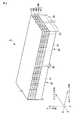
図2は、超音波探触子5の構成を示す斜視図である。図2に示すように、エレベーション(側面)方向に沿って結合される2つのモジュール30を有している。モジュール30の結合にはシリコーン接着等が用いられる。なお2つというのは一例であって、必要に応じて、3つ、4つ或いはそれ以上のモジュール30を結合させても良い。ここで、超音波探触子5の電子走査方向をアジマス(方位)方向、電子走査面に垂直な方向をエレベーション(側面)方向、アジマス方向とエレベーション方向とに垂直な方向をレンジ方向とする。 FIG. 2 is a perspective view showing the configuration of the
モジュール30は、吸音材としての背面材(バッキング材)41を有している。背面材41は矩形ブロック状に形成され、その上部にはフレキシブルPC板(FPC)43を介して複数の圧電振動子45が接合されている。 The
複数の圧電振動子45は、エレベーション方向及びアジマス(方位)方向に所定の間隔をあけて配列されており、2次元アレイ構造を成している。図2の例では複数の圧電振動子は、エレベーション方向に沿って12列、アジマス方向に沿って40列、計480個配列される。もちろんこれ以外の数の圧電振動子45を配列させても良い。各々の圧電振動子45は、圧電素子46、圧電素子46の下部に設けられた信号電極47及び圧電素子46の上部に設けられたアース電極48で構成されている。圧電振動子の配列に関する詳細は後述する。 The plurality of piezoelectric vibrators 45 are arranged at predetermined intervals in the elevation direction and the azimuth (azimuth) direction, and form a two-dimensional array structure. In the example of FIG. 2, a plurality of piezoelectric vibrators are arranged in a total of 480 pieces, 12 rows along the elevation direction and 40 rows along the azimuth direction. Of course, other numbers of piezoelectric vibrators 45 may be arranged. Each piezoelectric vibrator 45 includes a piezoelectric element 46, a
圧電素子46の素材は、2成分系或いは3成分系の圧電セラミックや圧電単結晶が用いられている。 As a material of the piezoelectric element 46, a two-component or three-component piezoelectric ceramic or a piezoelectric single crystal is used.
信号電極47は、銅箔などの金属箔で形成される。複数の信号電極47はフレキシブルPC板43に設けられた複数の配線に一つ一つ電気的に接続され、複数の圧電振動子45に対して独立に駆動信号を印加できるようになっている。 The
フレキシブルPC板43は、上述のように背面材41と圧電振動子45との間に設けられる。フレキシブルPC板43は、複数の信号電極47に電力を供給するための複数の配線及び柔軟性を有する基板等から構成されている。信号電極47と配線とは電気的に接続されており、信号電極47には超音波送信部11から所定の電圧が印加される。フレキシブルPC板43は、背面材41のエレベーション方向に関する両側面に沿って略90°に折り曲げられている。 The
アース電極48は、銅箔などの金属箔で形成される。複数のアース電極48は、超音波探触子5のエレベーション方向に沿う両側面に接続されたアース取り出し電極(図示せず)によって取り出される。アース取り出し電極は、アース電極48をアース接続するための電極である。図示しないが、アース取り出し電極は、超音波探触子5の両側面において、フレキシブルPC板43と接続され一体化される。 The
各々の圧電振動子45の上部はアース電極58を介して第1音響整合層49が接続されている。第1音響整合層49は導電性材料により形成される。第1音響整合層49の上部は第2音響整合層51と接合されている。第2音響整合層51は絶縁性材料により形成される。第1音響整合層49及び第2音響整合層51は、音響インピーダンスを圧電振動子45から被検体に向かって段階的に変化させるために設けられている。第2音響整合層51の上部は、全ての第2音響整合層51の上部を覆うように音響レンズ(図示せず)が設けられている。 A first
なお、本実施形態に係わる超音波探触子5は、第1音響整合層49及び第2音響整合層51を有する構成になっているが、第1音響整合層49のみ有する構成であってもよい。 Note that the
エレベーション方向及びアジマス方向に配列された複数の圧電振動子45、第1音響整合層49及び第2音響整合層51の間にある複数の隙間53には、エポキシ樹脂等の樹脂材やエポキシ樹脂等の樹脂材にフィラー材を混入させた複合充填材が充填さる。 In a plurality of
以下、図3及び図4を参照しながら、超音波探触子5の詳細な構造を説明する。 Hereinafter, the detailed structure of the
図3は、図2の超音波探触子5の簡略的な平面図であり、超音波探触子5の圧電振動子45のアレイを説明するための図である。図3に示すように、シリコーン接着による接着層35を介して2つのモジュール30(図3の太枠)が結合されている。1つのモジュール30には、エレベーション方向に沿って12列、アジマス方向に沿って40列、計480個の圧電振動子45が配列されている。アジマス方向の各列において、モジュール30のエレベーション方向に沿う内部には、エレベーション方向に沿って幅W1を有する10個の圧電振動子45aが設けられている。また、アジマス方向の各列において、モジュール30のエレベーション方向に沿う端部には、エレベーション方向に沿って幅W1よりも小さい幅W2を有する2個の圧電振動子45bが設けられている。 FIG. 3 is a simplified plan view of the
図3に示すように、超音波探触子5には、エレベーション方向に24列、アジマス方向に40列、計960個の圧電振動子45が設けられている。エレベーション方向に関して、超音波探触子5の両端部及び略中央にて隣り合う部分には圧電振動子45bが、残りの部分には圧電振動子45aが設けられている。 As shown in FIG. 3, the
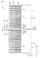
図4は、図3の4―4´断面図である。図4に示すように、モジュール30は、背面材41を有しており、背面材41の上部は厚みWFを有するフレキシブルPC板43を介して複数の圧電振動子45が接合されている。厚みWFは、典型的には50μmである。フレキシブルPC板43は、背面材41の両側面において略90°に折り曲げられている。モジュール30は、シリコーン接着等でエレベーション方向に結合される。シリコーン接着による接着層35の厚み(張り合わされる2つのフレキシブルPC板43間の距離)WAは、典型的には50μmである。 4 is a cross-sectional view taken along the line 4-4 ′ of FIG. As shown in FIG. 4, the
図4に示すように、幅W1を有する第1圧電振動子45aは、サブダイシングによってアジマス方向に沿って幅DSを有するサブダイシング溝が形成されている。幅W1は、典型的には250μmである。また、ダイシングによって形成されるダイシング溝53の幅WD及びサブダイシング溝55の幅WSは、典型的には、50μmである。サブダイシングによって2つに分断され且つエレベーション方向に沿って幅W3を有する第1圧電振動子45aの一部分を、第1圧電振動子片45cと称することにする。幅W3は、100μmである。従って第1圧電振動子45bの実行幅WE(2×W3=W1−DS)は200μmとなる。また、隣り合う2つの第1圧電振動子45aの中心間の距離(第1圧電振動子間ピッチ)p1は、300μmである。 As shown in FIG. 4, the first
図4に示すように、第2圧電振動子45bは、機械的強度の補強のためにサブダイシングされない。幅W2は、結合される2つの第2圧電振動子45bの中心間の距離(第2圧電振動子間ピッチ)p2が第1圧電振動子間ピッチp1と等しくなるように決められる。すなわち、幅W2は、150μmとなる。また、第1圧電振動子の中心と第2圧電振動子の中心との距離(第1圧電振動子―第2圧電振動子間ピッチ)p3は、250μmとなる。 As shown in FIG. 4, the second
以下、上記構成を有する超音波探触子5の効果を説明する。 Hereinafter, effects of the
(1)図7に示す従来の超音波探触子100の構成によれば、接着層を介して隣り合う2つの圧電振動子95aの中心間の距離p91は、モジュール内部において隣り合う2つの圧電振動子95bの中心間の距離p90よりも大きい。一方、図4に示す本実施形態に係わる超音波探触子5の構成によれば、モジュール30端部における圧電振動子45bの幅W2を、モジュール30内部における第1圧電振動子45aの幅W1よりも狭めている。従って、結合される2つの圧電振動子45bの中心間の距離である第2圧電振動子間ピッチp2とモジュール内部において隣り合う2つの圧電振動子45aの中心間の距離である第1圧電振動子間ピッチp1とを略等しくすることが可能である。その結果、超音波探触子5は、従来の超音波探触子100に比して、サイドローブの上昇が低減される。 (1) According to the configuration of the conventional
(2)サブダイシングされた場合において、図7に示す従来の超音波探触子100の構成によれば、モジュール端部における圧電振動子95aの幅W91は250μm、モジュール内部における圧電振動子95bの実行幅W99は200μmである。そのため、圧電振動子95aと圧電振動子95bとに同一の駆動電圧を印加した場合、圧電振動子95aから発生される超音波の強度は、圧電振動子95bから発生される超音波の強度よりも約2dB高い。一方、図4に示す本実施形態に係わる超音波探触子5の構成によれば、第2圧電振動子45bの幅W2を第1圧電振動子45aの幅W1よりも狭めることにより、第2圧電振動子45bの幅W2は、第1圧電振動子45aの実行幅WEよりも狭くなる。図4の例では、幅W3は150μm、幅WEは200μmであるため、圧電振動子45aと圧電振動子45bとに同一の駆動電圧を印加した場合、第2圧電振動子45bから発生される超音波の強度は、第1圧電振動子45aから発生される超音波の強度よりも約2dB小さくなる。その結果、超音波探触子5から発生される超音波の音場は逆ウェイティングにならない。すなわち、超音波探触子5は、従来の超音波探触子100に比してサイドローブの上昇が低減される。 (2) When sub-diced, according to the configuration of the conventional
以下、超音波探触子5から発せられる超音波の特性を図5に示すシミュレーション結果を参照しながら説明する。図5は、3Mz駆動、各圧電振動子同一駆動電圧、超音波ビームを45°偏向した場合における超音波の音場強度と超音波ビームの角度との関係を示す図である。実線は本実施形態における超音波探触子5によるデータ、破線は図7の従来の超音波探触子100によるデータを示す。2つのデータとも45°における音場強度を0としている。図5に示すように、本実施形態における超音波探触子5は、従来の超音波探触子100に比して、−40°〜+30°の広い範囲でサイドローブが低減する。 Hereinafter, the characteristics of the ultrasonic waves emitted from the
なお、上記構成において第1圧電振動子30は、サブダイシングされるものとして説明した。しかしながらこれに拘泥される必要はなく、第1圧電振動子30はサブダイシングされなくても良い。図6は、サブダイシングされていない超音波探触子の横断面図を示す図である。図6に示すように、第1圧電振動子45aの実行幅W1は250μmとなるから、第2圧電振動子45bから発生される超音波の強度は、第1圧電振動子45aから発生される超音波の強度よりも4dB低くなる。そのため、音場が逆ウェイティングにならず、その結果、サブダイシングされていない従来の超音波探触子に比して、図6の超音波探触子は、サイドローブの上昇が低減される。 In the above configuration, the first
また、上記構成においては、モジュール30の張り合わせ方向はエレベーション方向のみ考慮していた。しかしながら、モジュール30は、エレベーション方向だけでなくアジマス方向にも結合せることも可能である。すなわち、モジュール30を2次元状に結合させることも可能である。その際、アジマス方向において結合される2つの圧電振動子の中心間のアジマス方向に関する距離を、アジマス方向におけるモジュール内部の圧電振動子の中心間のアジマス方向に関する距離と等しくする。そのために、アジマス方向において結合される圧電振動子のアジマス方向に関する幅を、アジマス方向に関してモジュール内部の圧電振動子のアジマス方向に沿う幅よりも狭くすればよい。 Moreover, in the said structure, only the elevation direction was considered about the bonding direction of the
また、上記構成においては、圧電振動子は2次元状に配列されるとしたが、これに拘泥される必要はなく、圧電振動子をエレベーション方向又はアジマス方向に沿って1次元状に配列させてもよい。 In the above configuration, the piezoelectric vibrators are arranged in a two-dimensional manner. However, the piezoelectric vibrators are not necessarily limited to this, and the piezoelectric vibrators are arranged in a one-dimensional manner along the elevation direction or the azimuth direction. May be.
また、上記構成において、幅W3を有する第2圧電振動子45bが設けられる場所は、モジュール30の両端部とした。しかしながら、モジュール30の端部であるが結合されない部分には、幅W1を有する圧電振動子45aが設けられても良い。 Further, in the above configuration, the locations where the second
かくして本実施形態によれば、複数のモジュール30からなる超音波探触子5及び超音波診断装置1において、サイドローブ上昇の低減を可能とする。また、超音波探触子5を有する超音波診断装置1は、精度の良いBモード画像やドプラ画像等の超音波画像を提供することが可能となる。 Thus, according to the present embodiment, in the
なお、本発明は上記実施形態そのままに限定されるものではなく、実施段階ではその要旨を逸脱しない範囲で構成要素を変形して具体化できる。また、上記実施形態に開示されている複数の構成要素の適宜な組み合わせにより、種々の発明を形成できる。例えば、実施形態に示される全構成要素から幾つかの構成要素を削除してもよい。さらに、異なる実施形態にわたる構成要素を適宜組み合わせてもよい。 Note that the present invention is not limited to the above-described embodiment as it is, and can be embodied by modifying the constituent elements without departing from the scope of the invention in the implementation stage. In addition, various inventions can be formed by appropriately combining a plurality of components disclosed in the embodiment. For example, some components may be deleted from all the components shown in the embodiment. Furthermore, constituent elements over different embodiments may be appropriately combined.
1…超音波診断装置、5…超音波探触子、10…超音波診断装置本体、11…超音波送信部、12…超音波受信部、13…Bモード処理部、14…ドプラ処理部、15…スキャンコンバータ、16…画像合成部、17…モニター、18…記憶部、19…制御部、20…入力部、30…モジュール、35…接着層、41…背面材、43…フレキシブルPC板、45a…第1圧電振動子、45b…第2圧電振動子、45c…第1圧電振動子片、46…圧電素子、47…信号電極、48…アース電極、49…第1音響整合層、51…第2音響整合層、53…ダイシング溝、55…サブダイシング溝。 DESCRIPTION OF SYMBOLS 1 ... Ultrasonic diagnostic apparatus, 5 ... Ultrasonic probe, 10 ... Ultrasonic diagnostic apparatus main body, 11 ... Ultrasonic transmission part, 12 ... Ultrasonic reception part, 13 ... B mode processing part, 14 ... Doppler processing part, DESCRIPTION OF
Claims (7)
Translated fromJapanese前記複数のモジュールの各々は、
前記第1の方向に関して第1の幅を有する複数の第1圧電振動子と、
前記第1の方向に関して第1の幅よりも狭い第2の幅を有する少なくとも1つの第2圧電振動子と、を有し、
前記複数のモジュールは、前記第2圧電振動子において隣の前記モジュールと結合されることを特徴とする超音波探触子。In an ultrasound probe having a plurality of modules coupled at least in a first direction,
Each of the plurality of modules is
A plurality of first piezoelectric vibrators having a first width with respect to the first direction;
And at least one second piezoelectric vibrator having a second width narrower than the first width with respect to the first direction,
The ultrasonic probe according to claim 2, wherein the plurality of modules are coupled to the adjacent module in the second piezoelectric vibrator.
前記少なくとも2つの第1振動子群がなす少なくとも1つの間に配置され、前記第1の方向に関して前記第1の幅より狭い第2の幅を有し、前記第1の方向に2列及び前記第2の方向に複数配列される複数の第2圧電振動子を有する少なくとも1つの第2振動子群と、
を具備することを特徴とする超音波探触子。A plurality of first piezoelectric vibrators having a first width with respect to a first direction and a plurality of first piezoelectric vibrators arranged in a second direction different from the first direction and the first direction; At least two first vibrator groups arranged along a direction;
The at least two first vibrator groups are arranged between at least one, have a second width that is narrower than the first width with respect to the first direction, and two rows in the first direction and the row At least one second vibrator group having a plurality of second piezoelectric vibrators arranged in a second direction;
An ultrasonic probe comprising:
前記複数のモジュールの各々は、
前記第1の方向に関して第1の幅を有する複数の第1圧電振動子と、
前記第1の方向に関して第1の幅よりも狭い第2の幅を有する少なくとも1つの第2圧電振動子と、を有し、
前記複数のモジュールは、前記第2圧電振動子において隣のモジュールと結合されることを特徴とする超音波診断装置。Comprising an ultrasound probe having a plurality of modules coupled in at least a first direction;
Each of the plurality of modules is
A plurality of first piezoelectric vibrators having a first width with respect to the first direction;
And at least one second piezoelectric vibrator having a second width narrower than the first width with respect to the first direction,
The ultrasonic diagnostic apparatus, wherein the plurality of modules are coupled to an adjacent module in the second piezoelectric vibrator.
Priority Applications (5)
| Application Number | Priority Date | Filing Date | Title |
|---|---|---|---|
| JP2007260320AJP5002402B2 (en) | 2007-10-03 | 2007-10-03 | Ultrasonic probe and ultrasonic diagnostic apparatus |
| KR1020080093608AKR101172935B1 (en) | 2007-10-03 | 2008-09-24 | Ultrasonic probe and ultrasonic diagnostic apparatus |
| US12/240,232US8091428B2 (en) | 2007-10-03 | 2008-09-29 | Ultrasonic probe and ultrasonic diagnostic apparatus |
| CN201210109361.0ACN102631220B (en) | 2007-10-03 | 2008-10-06 | Ultrasonic probe and ultrasonic diagnostic apparatus |
| CN2008101689853ACN101404786B (en) | 2007-10-03 | 2008-10-06 | Ultrasonic probe and ultrasonic diagnostic apparatus |
Applications Claiming Priority (1)
| Application Number | Priority Date | Filing Date | Title |
|---|---|---|---|
| JP2007260320AJP5002402B2 (en) | 2007-10-03 | 2007-10-03 | Ultrasonic probe and ultrasonic diagnostic apparatus |
Publications (2)
| Publication Number | Publication Date |
|---|---|
| JP2009089738A JP2009089738A (en) | 2009-04-30 |
| JP5002402B2true JP5002402B2 (en) | 2012-08-15 |
Family
ID=40523876
Family Applications (1)
| Application Number | Title | Priority Date | Filing Date |
|---|---|---|---|
| JP2007260320AActiveJP5002402B2 (en) | 2007-10-03 | 2007-10-03 | Ultrasonic probe and ultrasonic diagnostic apparatus |
Country Status (4)
| Country | Link |
|---|---|
| US (1) | US8091428B2 (en) |
| JP (1) | JP5002402B2 (en) |
| KR (1) | KR101172935B1 (en) |
| CN (2) | CN102631220B (en) |
Families Citing this family (6)
| Publication number | Priority date | Publication date | Assignee | Title |
|---|---|---|---|---|
| JP6306048B2 (en)* | 2012-12-28 | 2018-04-04 | コーニンクレッカ フィリップス エヌ ヴェKoninklijke Philips N.V. | Acoustic probe having components of acoustic elements having different pitches |
| CN106575698B (en)* | 2014-08-18 | 2020-05-01 | 株式会社村田制作所 | Piezoelectric sensor and bending detection sensor |
| WO2017040979A1 (en) | 2015-09-03 | 2017-03-09 | Fujifilm Sonosite, Inc. | Ultrasound transducer assembly |
| GB2588218B (en)* | 2019-10-17 | 2021-10-27 | Darkvision Tech Ltd | Acoustic transducer and method of manufacturing |
| JP7616837B2 (en)* | 2020-07-29 | 2025-01-17 | キヤノンメディカルシステムズ株式会社 | Ultrasound probe |
| TWI871824B (en)* | 2023-11-07 | 2025-02-01 | 佳世達科技股份有限公司 | Ultrasonic transducers array and ultrasound probe |
Family Cites Families (18)
| Publication number | Priority date | Publication date | Assignee | Title |
|---|---|---|---|---|
| WO1991013588A1 (en)* | 1990-03-14 | 1991-09-19 | Fujitsu Limited | Ultrasonic probe |
| JPH06121390A (en)* | 1991-08-08 | 1994-04-28 | Terumo Corp | Ultrasonic search unit |
| JPH0576527A (en)* | 1991-09-24 | 1993-03-30 | Fujitsu Ltd | Ultrasonic probe and method for manufacturing composite piezoelectric vibrator used in the probe |
| JP3363999B2 (en) | 1994-04-28 | 2003-01-08 | 日本電波工業株式会社 | Ultrasonic transducer |
| JP3625564B2 (en)* | 1996-02-29 | 2005-03-02 | 株式会社日立メディコ | Ultrasonic probe and manufacturing method thereof |
| FR2756447B1 (en)* | 1996-11-26 | 1999-02-05 | Thomson Csf | MULTIPLE ELEMENT ACOUSTIC PROBE COMPRISING A COMMON MASS ELECTRODE |
| US6043589A (en)* | 1997-07-02 | 2000-03-28 | Acuson Corporation | Two-dimensional transducer array and the method of manufacture thereof |
| JP3384403B2 (en) | 2001-03-01 | 2003-03-10 | 株式会社村田製作所 | Surface acoustic wave device, communication device |
| JP2003009288A (en) | 2001-06-11 | 2003-01-10 | Ge Medical Systems Global Technology Co Llc | Piezoelectric device, ultrasonic wave probe and ultrasonic wave image pickup device |
| US6994674B2 (en)* | 2002-06-27 | 2006-02-07 | Siemens Medical Solutions Usa, Inc. | Multi-dimensional transducer arrays and method of manufacture |
| WO2004064614A2 (en)* | 2003-01-23 | 2004-08-05 | 3G Ultrasound, Inc. | Ultrasonic imaging device, system and method of use |
| JP2004251658A (en)* | 2003-02-18 | 2004-09-09 | Jfe Steel Kk | Ultrasonic angle beam probe |
| JP3982824B2 (en)* | 2004-03-04 | 2007-09-26 | 本多電子株式会社 | Array-type ultrasonic probe |
| JP2005296127A (en)* | 2004-04-07 | 2005-10-27 | Toshiba Corp | Ultrasonic probe and ultrasonic diagnostic apparatus |
| JP4693386B2 (en)* | 2004-10-05 | 2011-06-01 | 株式会社東芝 | Ultrasonic probe |
| EP1728563B1 (en) | 2005-05-30 | 2021-08-04 | Toshiba Medical Systems Corporation | Ultrasonic probe and ultrasonic probe manufacturing method |
| JP5132089B2 (en)* | 2005-06-16 | 2013-01-30 | 株式会社東芝 | Ultrasonic diagnostic apparatus, ultrasonic transmission / reception condition optimization program, and ultrasonic transmission / reception condition optimization method |
| JP4897370B2 (en)* | 2006-06-28 | 2012-03-14 | 富士フイルム株式会社 | Ultrasonic transducer array, ultrasonic probe, ultrasonic endoscope, ultrasonic diagnostic equipment |
- 2007
- 2007-10-03JPJP2007260320Apatent/JP5002402B2/enactiveActive
- 2008
- 2008-09-24KRKR1020080093608Apatent/KR101172935B1/enactiveActive
- 2008-09-29USUS12/240,232patent/US8091428B2/ennot_activeExpired - Fee Related
- 2008-10-06CNCN201210109361.0Apatent/CN102631220B/enactiveActive
- 2008-10-06CNCN2008101689853Apatent/CN101404786B/enactiveActive
Also Published As
| Publication number | Publication date |
|---|---|
| CN101404786B (en) | 2012-06-13 |
| KR101172935B1 (en) | 2012-08-10 |
| CN102631220B (en) | 2014-12-10 |
| US20090093722A1 (en) | 2009-04-09 |
| JP2009089738A (en) | 2009-04-30 |
| CN101404786A (en) | 2009-04-08 |
| CN102631220A (en) | 2012-08-15 |
| US8091428B2 (en) | 2012-01-10 |
| KR20090034731A (en) | 2009-04-08 |
Similar Documents
| Publication | Publication Date | Title |
|---|---|---|
| JP6147532B2 (en) | Ultrasonic probe | |
| JP6212870B2 (en) | Ultrasonic device, ultrasonic probe, electronic device and ultrasonic imaging apparatus | |
| EP2243561B1 (en) | Array of electroacoustic transducers and electronic probe for three-dimensional images comprising said transducer array | |
| JP5002402B2 (en) | Ultrasonic probe and ultrasonic diagnostic apparatus | |
| JP5357388B2 (en) | Interconnect structure for transducer assembly | |
| US20120004554A1 (en) | Ultrasound probe and ultrasound imaging apparatus | |
| JP6281262B2 (en) | Ultrasonic device and probe, electronic apparatus and ultrasonic imaging apparatus | |
| JP2022509381A (en) | Scanning device | |
| KR102406927B1 (en) | Ultrasound probe and manufacturing method for the same | |
| JP5461769B2 (en) | Ultrasonic transducer, ultrasonic probe, and method of manufacturing ultrasonic transducer | |
| JP2004033666A (en) | Ultrasonic probe and ultrasonographic apparatus | |
| JP2018114042A (en) | Ultrasound probe, ultrasound diagnostic apparatus, and semiconductor sensor | |
| US20160317125A1 (en) | Ultrasonic device unit, probe, electronic apparatus, and ultrasonic diagnostic apparatus | |
| JP4982135B2 (en) | Ultrasonic transducer | |
| JP4795707B2 (en) | Ultrasonic probe and ultrasonic diagnostic apparatus | |
| JP2010219774A (en) | Ultrasound transducer, ultrasound probe, and ultrasound diagnostic apparatus | |
| JP2016030037A (en) | Ultrasonic probe and ultrasonic probe manufacturing method | |
| JP2005328507A (en) | Ultrasonic probe and ultrasonic diagnostic apparatus | |
| JP2017086156A (en) | Ultrasonic imaging device, control device for ultrasonic imaging device, and ultrasonic image forming method | |
| JP6451216B2 (en) | Ultrasonic probe, electronic device and ultrasonic imaging device | |
| JP5299128B2 (en) | Ultrasonic probe, ultrasonic diagnostic equipment | |
| US20130253326A1 (en) | Method and system for interfacing high-density transducer arrays | |
| JP2017063383A (en) | Ultrasonic probe | |
| JPS6279046A (en) | Electronic scanning ultrasonic tomography device |
Legal Events
| Date | Code | Title | Description |
|---|---|---|---|
| A621 | Written request for application examination | Free format text:JAPANESE INTERMEDIATE CODE: A621 Effective date:20100924 | |
| TRDD | Decision of grant or rejection written | ||
| A01 | Written decision to grant a patent or to grant a registration (utility model) | Free format text:JAPANESE INTERMEDIATE CODE: A01 Effective date:20120424 | |
| A01 | Written decision to grant a patent or to grant a registration (utility model) | Free format text:JAPANESE INTERMEDIATE CODE: A01 | |
| A977 | Report on retrieval | Free format text:JAPANESE INTERMEDIATE CODE: A971007 Effective date:20120425 | |
| A61 | First payment of annual fees (during grant procedure) | Free format text:JAPANESE INTERMEDIATE CODE: A61 Effective date:20120521 | |
| R150 | Certificate of patent or registration of utility model | Ref document number:5002402 Country of ref document:JP Free format text:JAPANESE INTERMEDIATE CODE: R150 Free format text:JAPANESE INTERMEDIATE CODE: R150 | |
| FPAY | Renewal fee payment (event date is renewal date of database) | Free format text:PAYMENT UNTIL: 20150525 Year of fee payment:3 | |
| RD04 | Notification of resignation of power of attorney | Free format text:JAPANESE INTERMEDIATE CODE: A7424 Effective date:20120529 | |
| A072 | Dismissal of procedure [no reply to invitation to correct request for examination] | Free format text:JAPANESE INTERMEDIATE CODE: A072 Effective date:20121030 | |
| S111 | Request for change of ownership or part of ownership | Free format text:JAPANESE INTERMEDIATE CODE: R313115 Free format text:JAPANESE INTERMEDIATE CODE: R313117 | |
| R350 | Written notification of registration of transfer | Free format text:JAPANESE INTERMEDIATE CODE: R350 | |
| S533 | Written request for registration of change of name | Free format text:JAPANESE INTERMEDIATE CODE: R313533 | |
| R350 | Written notification of registration of transfer | Free format text:JAPANESE INTERMEDIATE CODE: R350 |