JP5001799B2 - Wire harness wiring structure for robot joints - Google Patents
Wire harness wiring structure for robot jointsDownload PDFInfo
- Publication number
- JP5001799B2 JP5001799B2JP2007304587AJP2007304587AJP5001799B2JP 5001799 B2JP5001799 B2JP 5001799B2JP 2007304587 AJP2007304587 AJP 2007304587AJP 2007304587 AJP2007304587 AJP 2007304587AJP 5001799 B2JP5001799 B2JP 5001799B2
- Authority
- JP
- Japan
- Prior art keywords
- joint
- wire harness
- forming member
- joint forming
- robot
- Prior art date
- Legal status (The legal status is an assumption and is not a legal conclusion. Google has not performed a legal analysis and makes no representation as to the accuracy of the status listed.)
- Expired - Fee Related
Links
Images


Landscapes
- Manipulator (AREA)
Description
Translated fromJapanese本発明は、例えばロボットアーム等の関節にワイヤハーネスを配線するロボット関節のワイヤハーネス配線構造に関するものである。 The present invention relates to a wire harness wiring structure of a robot joint for wiring a wire harness to a joint such as a robot arm.
従来におけるロボット関節のワイヤハーネス配線構造としては、例えば特許文献1に記載されているように、ワイヤハーネスを関節部に螺旋状に巻き付けてなるものが知られている。
しかしながら、上記従来技術のようにワイヤハーネスを関節部に螺旋状に巻き付けると、関節部の外径が大きくなってしまう。このため、例えば関節部にアクチュエータ等が内蔵されている場合には、ロボット自体が大型になるばかりでなく、ロボットの外形形状の悪化につながる。 However, when the wire harness is wound around the joint in a spiral manner as in the prior art, the outer diameter of the joint becomes large. For this reason, for example, when an actuator or the like is built in the joint portion, the robot itself is not only large, but also the external shape of the robot is deteriorated.
本発明の目的は、ロボットの外形形状を最適化することができるロボット関節のワイヤハーネス配線構造を提供することである。 The objective of this invention is providing the wire harness wiring structure of the robot joint which can optimize the external shape of a robot.
本発明は、互いに相対回転可能な第1関節形成部材及び第2関節形成部材を備えたロボット関節にワイヤハーネスを配線するロボット関節のワイヤハーネス配線構造において、第1関節形成部材に固定され、第2関節形成部材側に向かって延在するバイパス部材を設け、バイパス部材の先端と第2関節形成部材との境界部を含む部分にワイヤハーネスを可動となるように配線し、バイパス部材は、第2関節形成部材の一部を取り囲むように配置された筒状部と、第1関節形成部材と筒状部とを繋ぐ連結部とを有し、ワイヤハーネスは、筒状部と第2関節形成部材との境界部を含む部分に可動となるように配線されており、筒状部と第2関節形成部材との間にはベアリングが介在されていることを特徴とするものである。The present invention relates to a wire harness wiring structure for a robot joint in which a wire harness is wired to a robot joint having a first joint forming member and a second joint forming member that can rotate relative to each other, and is fixed to the first joint forming member. (2) A bypass member extending toward the joint forming member side is provided, and a wire harness is movably wired at a portion including a boundary portion between the tip of the bypass member and the second joint forming member. A tubular part disposed so as to surround a part of the two joint-forming members, and a connecting part that connects the first joint-forming member and the tubular part, and the wire harness includes the tubular part and the second joint-forming member. It is wired so as to be movable in a portion including the boundary with the member, and a bearing is interposed between the tubular portion and the second joint forming member .
例えばロボット関節において、第1関節形成部材と第2関節形成部材との境界部分の外径が第2関節形成部材の他の部分の外径よりも大きい場合には、第1関節形成部材と第2関節形成部材との境界部分にワイヤハーネスを配線すると、当該境界部分の外径が更に大きくなる。このため、ロボット関節の外面に存在する凹凸が増大する。そのような場合、本発明のワイヤハーネス配線構造では、第1関節形成部材から第2関節形成部材の上記他の部分まで延在するバイパス部材を設け、このバイパス部材の先端と第2関節形成部材との境界部を含む部分にワイヤハーネスを可動となるように配線することにより、ロボット関節の外面に存在する凹凸が小さくなる。これにより、ロボット関節の外形形状を最適化することができる。 For example, in a robot joint, when the outer diameter of the boundary portion between the first joint forming member and the second joint forming member is larger than the outer diameter of the other portion of the second joint forming member, the first joint forming member and the second joint forming member When the wire harness is wired at the boundary portion with the two joint forming members, the outer diameter of the boundary portion is further increased. For this reason, the unevenness | corrugation which exists in the outer surface of a robot joint increases. In such a case, in the wire harness wiring structure of the present invention, a bypass member extending from the first joint forming member to the other portion of the second joint forming member is provided, and the tip of the bypass member and the second joint forming member are provided. By wiring the wire harness so as to be movable in the portion including the boundary portion, the unevenness existing on the outer surface of the robot joint is reduced. Thereby, the external shape of the robot joint can be optimized.
また、バイパス部材は、第2関節形成部材の一部を取り囲むように配置された筒状部と、第1関節形成部材と筒状部とを繋ぐ連結部とを有し、ワイヤハーネスは、筒状部と第2関節形成部材との境界部を含む部分に可動となるように配線されている。この場合には、バイパス部材を簡単な構造で且つ確実に実現できると共に、バイパス部材の筒状部と第2関節形成部材との境界部を含む部分にワイヤハーネスを容易に可動となるように配線することができる。The bypass member includes a cylindrical portion disposed so as to surround a part of the second joint forming member, and a connecting portion that connects the first joint forming memberand the cylindrical portion. It is wired so as to be movable at a portion including the boundary portion between the shape portion and the second joint forming member. In this case, the bypass member can be realized with a simple structure and surely, and the wiring harness can be easily moved in a portion including the boundary portion between the tubular portion of the bypass member and the second joint forming member. can do.
このとき、筒状部と第2関節形成部材との間にはベアリングが介在されている。この場合には、例えばバイパス部材の剛性が低い場合でも、バイパス部材の筒状部の揺れ動きが抑制されるようになる。At this time, between the cylindrical portion and the second joint member bearingthat isinterposed. In this case, for example, even when the rigidity of the bypass member is low, the swinging movement of the tubular portion of the bypass member is suppressed.
本発明によれば、ロボットの外形形状を最適化することができるので、ロボットの性能向上等を図ることが可能となる。 According to the present invention, since the outer shape of the robot can be optimized, it is possible to improve the performance of the robot.
以下、本発明に係わるロボット関節のワイヤハーネス配線構造の好適な実施形態について、図面を参照して詳細に説明する。 Preferred embodiments of a wire harness wiring structure for a robot joint according to the present invention will be described below in detail with reference to the drawings.
図1は、本発明に係わるロボット関節のワイヤハーネス配線構造の一実施形態が適用されるロボットの一例の外観を示す斜視図である。同図において、ロボット1は、4つの車輪2aを有する移動ベース2を備え、この移動ベース2の上面にはロボット胴体3が固定されている。ロボット胴体3の上部には、ロボット頭部4と2本のロボットアーム5が取り付けられている。各ロボットアーム5の先端にはロボットハンド6が連結され、このロボットハンド6には作業用エンドエフェクタ7が設けられている。 FIG. 1 is a perspective view showing an appearance of an example of a robot to which an embodiment of a wire harness wiring structure for a robot joint according to the present invention is applied. In the figure, a
ロボットアーム5は、ロボット胴体3に旋回関節8を介して連結された屈曲関節9と、この屈曲関節9に旋回関節10を介して連結された屈曲関節11とを有している。ロボットハンド6は、屈曲関節11に旋回関節12を介して連結されている。なお、ロボット頭部4及びロボット胴体3の上部は、旋回関節構造を有している。 The
図2は、旋回関節10の具体的構造を示す断面図である。同図において、旋回関節10は、屈曲関節9に結合された関節形成部材13と、屈曲関節11に結合された関節形成部材14とを有している。旋回関節10は、関節形成部材13,14同士が軸P回りに相対回転することで旋回運動する関節である。 FIG. 2 is a cross-sectional view showing a specific structure of the
関節形成部材13は、筒状部15と、この筒状部15から外側に突出するように設けられた環状突部16とを有している。関節形成部材14は、筒状部17と、この筒状部17と屈曲関節11との間に設けられた連結部18とを有している。筒状部17は、環状突部16と並ぶように筒状部15の外側に配置されている。環状突部16の外周面と筒状部17の外周面は、ほぼ面一となっている。また、これらの環状突部16及び筒状部17の外径D1は、関節形成部材14の連結部18の外径D2よりも大きくなっている。 The
筒状部15,17間にはベアリング19が介在されており、関節形成部材13,14が軸P回りにベアリング19を介して相対的に回転可能となっている。ベアリング19としては、例えばラジアル及びスラストの両方向に対して位置決め可能なクロスローラベアリング等が用いられる。 A
また、旋回関節10は、関節形成部材13,14を軸P回りに相対回転させる駆動部20を更に有している。駆動部20は、モータ及び減速機からなるアクチュエータ21と、関節形成部材13に固定された内ハウジング22と、関節形成部材14に固定された外ハウジング23とを有し、これらのハウジング22,23間にアクチュエータ21が配置されている。また、ハウジング22,23間には、2つのベアリング24が介在されている。アクチュエータ21により内ハウジング22及び外ハウジング23が相対回転し、これに伴って関節形成部材13,14が相対回転する。 Further, the
このような旋回関節10には、電線や電気ケーブルを加工してなるワイヤハーネス25が屈曲関節9側から屈曲関節11側に向かって通っており、ワイヤハーネス25の途中でワイヤハーネス25aが分岐されてアクチュエータ21に結線されている。これにより、アクチュエータ21に電気が供給され、アクチュエータ21が駆動されるようになる。 In such a
関節形成部材13の環状突部16の外周面には、ワイヤハーネス25を適切な箇所に配線すべく、関節形成部材13,14の境界部を移すためのバイパス部材26が固定されている。バイパス部材26は、環状突部16の外周面から関節形成部材14側(屈曲関節11側)に向かって延在している。これにより、関節形成部材13,14が相対回転すると、バイパス部材26と関節形成部材14とが相対回転することとなる。 A
バイパス部材26は、関節形成部材14の連結部18の一部を取り囲むように配置された筒状部27と、環状突部16と筒状部27とを繋ぐ断面略L字状の連結部28とを有している。連結部28は、円筒形を有する形状であっても良いし、関節形成部材14の周方向に断続的に設けられた橋渡し形状であっても良い。 The
筒状部27は、連結部18における関節形成部材13側(屈曲関節9側)の部位に形成された環状溝部18aに配置されている。連結部18における屈曲関節11側の部位の外周面と筒状部27の外周面は、ほぼ面一になっている。 The
また、筒状部27と連結部18との間には、ベアリング29が介在されている。これにより、バイパス部材26の剛性が高くなり、バイパス部材26と関節形成部材14との相対回転時にバイパス部材26がぐらつくことが防止される。 A
このようなバイパス部材26を設けることにより、関節形成部材13,14の境界部としては、環状突部16と筒状部17との境界部からバイパス部材26の先端と連結部18との境界部に移されることとなる。そして、上記のワイヤハーネス25は、バイパス部材26と連結部18との境界部を含む部分に可動となるように配線される。 By providing such a
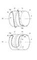
ところで、関節形成部材13,14が相対回転動作すると、バイパス部材26の筒状部27と連結部18との境界部分でワイヤハーネス25のねじれが発生するので、ワイヤハーネス25が引っ張られたり負荷になってしまう。このため、ワイヤハーネス25の配線(取り回し)は、図3に示すように行われる。 By the way, when the
図3(a)に示す構造では、筒状部27と連結部18との境界部を含む部分においてワイヤハーネス25を螺旋状に巻き付ける。そして、筒状部27の外周面にワイヤハーネス25をテープ等で固定してなるワイヤ留め部30aを設けると共に、連結部18の外周面にワイヤハーネス25を同様にして固定してなるワイヤ留め部30bを設ける。この場合には、関節形成部材13に対して関節形成部材14を回転させると、ワイヤハーネス25が2点鎖線Rで示すように移動する。 In the structure shown in FIG. 3A, the
図3(b)に示す構造では、筒状部27と連結部18との境界部を含む部分においてワイヤハーネス25をU字状に配置する。そして、上記と同様に、筒状部27の外周面にワイヤ留め部30aを設けると共に、連結部18の外周面にワイヤ留め部30bを設ける。この場合には、関節形成部材13に対して関節形成部材14を回転させると、ワイヤハーネス25が2点鎖線Sで示すように移動する。 In the structure shown in FIG. 3B, the
上記の何れの構造においても、関節形成部材13,14の相対回転時にワイヤハーネス25がスムーズに動くように、余裕のあるスペースを確保したケース31(図2参照)にワイヤハーネス25を収容する。このとき、ワイヤハーネス25を螺旋状に巻き付けた構造では、関節形成部材13,14が相対回転すると、ワイヤハーネス25が外側に撓むようになるために、その分を考慮した厚さを有するケース31が必要となる。 In any of the structures described above, the
ここで、比較例として、従来におけるロボット関節のワイヤハーネス配線構造の一例を図4に示す。同図において、本比較例のワイヤハーネス配線構造では、本実施形態のようなバイパス部材26が設けられておらず、関節形成部材13の環状突部16と関節形成部材14の筒状部17との境界部を含む部分にワイヤハーネス25が取り回されている。 Here, as a comparative example, an example of a conventional wire harness wiring structure of a robot joint is shown in FIG. In the figure, in the wire harness wiring structure of this comparative example, the
このような構造では、環状突部16及び筒状部17の外周面側にワイヤハーネス25を収容したケース31を含むスペースが必要となる。その結果、ワイヤハーネス25及びケース31を含むロボットアーム5の外形形状は、図4中の2点鎖線Q’に示すようになる。つまり、環状突部16と筒状部17との境界部分の外径D3が関節形成部材14の連結部18の外径D4に比べて極めて大きくなってしまう。このため、ロボットアーム5の外面の凹凸が大きくなり、外観的にもロボットアーム5の見栄えが悪くなる。 In such a structure, a space including the
これに対し本実施形態では、関節形成部材13の環状突部16から関節形成部材14の連結部18まで延びるバイパス部材26を設け、このバイパス部材26の筒状部27と連結部18との境界部を含む部分にワイヤハーネス25を取り回すような構造としたので、関節形成部材14において最も外径の小さい連結部18の外周面側にワイヤハーネス25を収容したケース31が配置されることとなる。その結果、ワイヤハーネス25及びケース31を含むロボットアーム5の外形形状は、図2中の2点鎖線Qに示すようになる。つまり、元々最小径部である連結部8の外径D4のみが増大し、環状突部16と筒状部17との境界部分の外径D3を増大させなくて済む。これにより、ロボットアーム5のサイズの増大が抑えられると共に、ロボットアーム5の外面の凹凸を小さくすることができる。 In contrast, in the present embodiment, a
このようにロボットアーム5の外径形状を最適化することにより、旋回関節10の可動角が大きくとれるようになり、ロボットの性能を向上させることができる。また、ロボットアーム5の外面の凹凸が少なくなるため、外観的にロボットアーム5の見栄えが良好なものとなる。 Thus, by optimizing the outer diameter shape of the
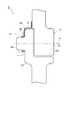
図5は、屈曲関節9の構造の一例を簡略化して示す断面図である。同図において、屈曲関節9は、旋回関節8に結合された関節形成部材32と、旋回関節10に結合された関節形成部材33とを有している。屈曲関節9は、関節形成部材32,33同士が軸P回りに相対回転することで屈曲運動する関節である。 FIG. 5 is a cross-sectional view schematically showing an example of the structure of the bending joint 9. In the figure, the bending joint 9 has a joint forming
関節形成部材33の一側面には、略円柱状の突起部34が設けられている。突起部34は、その中心軸が軸Pに一致するように構成されている。 On one side surface of the joint forming
関節形成部材32の外面には、ワイヤハーネス25(図2参照)を適切な箇所に配線すべく、関節形成部材32,33の境界部を移すためのバイパス部材35が固定されている。バイパス部材35は、関節形成部材32から関節形成部材33側に向かって突起部34まで延在している。これにより、関節形成部材32,33が相対回転すると、バイパス部材35と関節形成部材33とが相対回転することとなる。 On the outer surface of the joint forming
バイパス部材35は、突起部34の一部を取り囲むように配置された筒状部36と、関節形成部材32と筒状部36とを繋ぐ断面略L字状の連結部37とを有している。連結部37は、橋渡し形状となっているが、円筒形状であっても良い。また、筒状部36と突起部34との間にはベアリングが介在されていても良い。 The
このような屈曲関節9では、バイパス部材35の筒状部36と突起部34との境界部を含む部分にワイヤハーネス25が可動となるように螺旋状またはU字状に取り回される(図3参照)。つまり、筒状部36と突起部34との境界部分の外側にワイヤハーネス25を収容したケース31が配置されることになる。これにより、屈曲関節9の外径D5の増大が抑えられ、ロボットアーム5の外形形状の小型化及び最適化を図ることができる。 In such a bending joint 9, the
他の旋回関節8,12についても、上記の旋回関節10と同様のワイヤハーネス配線構造が採用される。また、他の屈曲関節11についても、上記の屈曲関節9と同様のワイヤハーネス配線構造が採用される。 For the
なお、本発明は、上記実施形態に限定されるものではない。例えば上記実施形態では、関節形成部材の外径の小さい部分にワイヤハーネスを配線するようにバイパス部材を構成することにより、ロボットアーム自体の小型化及びロボットアームの凹凸の低減化を図るようにしたが、ロボットの種類、構造及び用途等によっては、関節形成部材の外径の大きい部分に積極的にワイヤハーネスを配線するようにバイパス部材を設けても良い。要は、バイパス部材を設けてワイヤハーネスの取り回し位置を変えることで、特に大きな設計変更を行わなくても、ロボットアームの外径形状を自由に変えることが可能となる。 The present invention is not limited to the above embodiment. For example, in the above-described embodiment, the bypass member is configured so that the wire harness is wired to the portion having a small outer diameter of the joint forming member, thereby reducing the size of the robot arm itself and reducing the unevenness of the robot arm. However, depending on the type, structure, application, etc. of the robot, a bypass member may be provided so as to positively wire the wire harness to a portion having a large outer diameter of the joint forming member. In short, by providing a bypass member and changing the routing position of the wire harness, it is possible to freely change the outer diameter shape of the robot arm without making a particularly large design change.
また、上記実施形態は、ロボットアームの旋回関節及び屈曲関節にワイヤハーネスを配線する構造であるが、本発明は、ロボットハンドの各指の関節やロボット脚部の関節に対しても適用可能である。 In the above embodiment, the wire harness is wired to the turning joint and the bending joint of the robot arm. However, the present invention can also be applied to the joint of each finger of the robot hand and the joint of the robot leg. is there.
5…ロボットアーム、8…旋回関節、9…屈曲関節、10…旋回関節、11…屈曲関節、12…旋回関節、13…関節形成部材(第1関節形成部材)、14…関節形成部材(第2関節形成部材)、25…ワイヤハーネス、26…バイパス部材、27…筒状部、28…連結部、29…ベアリング、32…関節形成部材(第1関節形成部材)、33…関節形成部材(第2関節形成部材)、35…バイパス部材、36…筒状部、37…連結部。
DESCRIPTION OF
Claims (1)
Translated fromJapanese前記第1関節形成部材に固定され、前記第2関節形成部材側に向かって延在するバイパス部材を設け、
前記バイパス部材の先端と前記第2関節形成部材との境界部を含む部分に前記ワイヤハーネスを可動となるように配線し、
前記バイパス部材は、前記第2関節形成部材の一部を取り囲むように配置された筒状部と、前記第1関節形成部材と前記筒状部とを繋ぐ連結部とを有し、
前記ワイヤハーネスは、前記筒状部と前記第2関節形成部材との境界部を含む部分に可動となるように配線されており、
前記筒状部と前記第2関節形成部材との間にはベアリングが介在されていることを特徴とするロボット関節のワイヤハーネス配線構造。In a wire harness wiring structure of a robot joint that routes a wire harness to a robot joint provided with a first joint forming member and a second joint forming member that can rotate relative to each other,
A bypass member fixed to the first joint forming member and extending toward the second joint forming member side;
Wiring the wire harness to be movable at a portion including the boundary between the tip of the bypass member and the second joint forming member,
The bypass member includes a cylindrical portion disposed so as to surround a part of the second joint forming member, and a connecting portion that connects the first joint forming member and the cylindrical portion,
The wire harness is wired so as to be movable at a portion including a boundary portion between the tubular portion and the second joint forming member,
A wire harness wiring structure for a robot joint,wherein a bearing is interposed between the tubular portion and the second joint forming member .
Priority Applications (1)
| Application Number | Priority Date | Filing Date | Title |
|---|---|---|---|
| JP2007304587AJP5001799B2 (en) | 2007-11-26 | 2007-11-26 | Wire harness wiring structure for robot joints |
Applications Claiming Priority (1)
| Application Number | Priority Date | Filing Date | Title |
|---|---|---|---|
| JP2007304587AJP5001799B2 (en) | 2007-11-26 | 2007-11-26 | Wire harness wiring structure for robot joints |
Publications (2)
| Publication Number | Publication Date |
|---|---|
| JP2009125874A JP2009125874A (en) | 2009-06-11 |
| JP5001799B2true JP5001799B2 (en) | 2012-08-15 |
Family
ID=40817298
Family Applications (1)
| Application Number | Title | Priority Date | Filing Date |
|---|---|---|---|
| JP2007304587AExpired - Fee RelatedJP5001799B2 (en) | 2007-11-26 | 2007-11-26 | Wire harness wiring structure for robot joints |
Country Status (1)
| Country | Link |
|---|---|
| JP (1) | JP5001799B2 (en) |
Cited By (1)
| Publication number | Priority date | Publication date | Assignee | Title |
|---|---|---|---|---|
| WO2022060722A1 (en)* | 2020-09-18 | 2022-03-24 | Boston Dynamics, Inc. | Omega wire routing |
Families Citing this family (2)
| Publication number | Priority date | Publication date | Assignee | Title |
|---|---|---|---|---|
| JP5540981B2 (en)* | 2010-08-09 | 2014-07-02 | 株式会社デンソーウェーブ | Articulated robot |
| CN114347097A (en)* | 2022-01-27 | 2022-04-15 | 南京蔚蓝智能科技有限公司 | Method and device for accommodating robot joint lead |
Family Cites Families (3)
| Publication number | Priority date | Publication date | Assignee | Title |
|---|---|---|---|---|
| JPS5936391Y2 (en)* | 1979-07-16 | 1984-10-06 | 株式会社明電舎 | Manipulator. Wiring structure in arm |
| JPH08155880A (en)* | 1994-12-05 | 1996-06-18 | Fanuc Ltd | Cable handling device of industrial robot |
| JP3746244B2 (en)* | 2002-04-10 | 2006-02-15 | ファナック株式会社 | Laying structure of the striatum on the wrist of the robot |
- 2007
- 2007-11-26JPJP2007304587Apatent/JP5001799B2/ennot_activeExpired - Fee Related
Cited By (3)
| Publication number | Priority date | Publication date | Assignee | Title |
|---|---|---|---|---|
| WO2022060722A1 (en)* | 2020-09-18 | 2022-03-24 | Boston Dynamics, Inc. | Omega wire routing |
| US11707854B2 (en) | 2020-09-18 | 2023-07-25 | Boston Dynamics, Inc. | Omega wire routing |
| US12233543B2 (en) | 2020-09-18 | 2025-02-25 | Boston Dynamics, Inc. | Wire routing for robotic manipulator |
Also Published As
| Publication number | Publication date |
|---|---|
| JP2009125874A (en) | 2009-06-11 |
Similar Documents
| Publication | Publication Date | Title |
|---|---|---|
| US7513174B2 (en) | Industrial robot | |
| JP2014030893A (en) | robot | |
| EP3010684B1 (en) | A rotary joint of a robot and the robot including the same | |
| EP2364821B1 (en) | Robot with seven joints | |
| JP6337432B2 (en) | Joint drive device and robot | |
| CN106687259B (en) | Cable management system, rotary joint and robot | |
| JP3830488B2 (en) | Wiring and piping processing equipment | |
| JPH09267289A (en) | Industrial robot | |
| JP6849363B2 (en) | Rotating actuators and robots | |
| CN110202611B (en) | robot | |
| JP2010094749A (en) | Articulated robot and robot system | |
| WO2014185373A1 (en) | Link actuation device | |
| JP5001799B2 (en) | Wire harness wiring structure for robot joints | |
| JP2011194495A (en) | Arm connecting device of robot | |
| JP2016068201A (en) | robot | |
| JP7290312B2 (en) | Actuator and SCARA robot | |
| JP2007175849A (en) | robot | |
| JPH01306193A (en) | Cable process device at joint part of robot for industrial use | |
| WO2016092627A1 (en) | Robot | |
| JP2006007355A (en) | Robot wrist device | |
| JPH07328982A (en) | Wiring and piping structure of articulated robot | |
| JP2012101324A (en) | Mechanical restriction of rotation in rotary joint for robot | |
| JP2009125885A (en) | Cable wiring structure | |
| JP2012187667A (en) | Multijoint robot | |
| JP7497018B2 (en) | Robot Hand |
Legal Events
| Date | Code | Title | Description |
|---|---|---|---|
| A621 | Written request for application examination | Free format text:JAPANESE INTERMEDIATE CODE: A621 Effective date:20100302 | |
| A977 | Report on retrieval | Free format text:JAPANESE INTERMEDIATE CODE: A971007 Effective date:20110922 | |
| A131 | Notification of reasons for refusal | Free format text:JAPANESE INTERMEDIATE CODE: A131 Effective date:20111018 | |
| A521 | Request for written amendment filed | Free format text:JAPANESE INTERMEDIATE CODE: A523 Effective date:20111206 | |
| TRDD | Decision of grant or rejection written | ||
| A01 | Written decision to grant a patent or to grant a registration (utility model) | Free format text:JAPANESE INTERMEDIATE CODE: A01 Effective date:20120424 | |
| A01 | Written decision to grant a patent or to grant a registration (utility model) | Free format text:JAPANESE INTERMEDIATE CODE: A01 | |
| A61 | First payment of annual fees (during grant procedure) | Free format text:JAPANESE INTERMEDIATE CODE: A61 Effective date:20120518 | |
| R151 | Written notification of patent or utility model registration | Ref document number:5001799 Country of ref document:JP Free format text:JAPANESE INTERMEDIATE CODE: R151 | |
| FPAY | Renewal fee payment (event date is renewal date of database) | Free format text:PAYMENT UNTIL: 20150525 Year of fee payment:3 | |
| R250 | Receipt of annual fees | Free format text:JAPANESE INTERMEDIATE CODE: R250 | |
| R250 | Receipt of annual fees | Free format text:JAPANESE INTERMEDIATE CODE: R250 | |
| R250 | Receipt of annual fees | Free format text:JAPANESE INTERMEDIATE CODE: R250 | |
| R250 | Receipt of annual fees | Free format text:JAPANESE INTERMEDIATE CODE: R250 | |
| R250 | Receipt of annual fees | Free format text:JAPANESE INTERMEDIATE CODE: R250 | |
| R250 | Receipt of annual fees | Free format text:JAPANESE INTERMEDIATE CODE: R250 | |
| R250 | Receipt of annual fees | Free format text:JAPANESE INTERMEDIATE CODE: R250 | |
| LAPS | Cancellation because of no payment of annual fees |