JP4998581B2 - Gas turbine combustor and method of operating gas turbine combustor - Google Patents
Gas turbine combustor and method of operating gas turbine combustorDownload PDFInfo
- Publication number
- JP4998581B2 JP4998581B2JP2010094596AJP2010094596AJP4998581B2JP 4998581 B2JP4998581 B2JP 4998581B2JP 2010094596 AJP2010094596 AJP 2010094596AJP 2010094596 AJP2010094596 AJP 2010094596AJP 4998581 B2JP4998581 B2JP 4998581B2
- Authority
- JP
- Japan
- Prior art keywords
- fuel
- air
- combustion chamber
- combustion
- combustor
- Prior art date
- Legal status (The legal status is an assumption and is not a legal conclusion. Google has not performed a legal analysis and makes no representation as to the accuracy of the status listed.)
- Expired - Lifetime
Links
Images


Classifications
- F—MECHANICAL ENGINEERING; LIGHTING; HEATING; WEAPONS; BLASTING
- F23—COMBUSTION APPARATUS; COMBUSTION PROCESSES
- F23R—GENERATING COMBUSTION PRODUCTS OF HIGH PRESSURE OR HIGH VELOCITY, e.g. GAS-TURBINE COMBUSTION CHAMBERS
- F23R3/00—Continuous combustion chambers using liquid or gaseous fuel
- F23R3/28—Continuous combustion chambers using liquid or gaseous fuel characterised by the fuel supply
- F23R3/36—Supply of different fuels
- F—MECHANICAL ENGINEERING; LIGHTING; HEATING; WEAPONS; BLASTING
- F23—COMBUSTION APPARATUS; COMBUSTION PROCESSES
- F23R—GENERATING COMBUSTION PRODUCTS OF HIGH PRESSURE OR HIGH VELOCITY, e.g. GAS-TURBINE COMBUSTION CHAMBERS
- F23R3/00—Continuous combustion chambers using liquid or gaseous fuel
- F23R3/02—Continuous combustion chambers using liquid or gaseous fuel characterised by the air-flow or gas-flow configuration
- F23R3/04—Air inlet arrangements
- F23R3/10—Air inlet arrangements for primary air
- F—MECHANICAL ENGINEERING; LIGHTING; HEATING; WEAPONS; BLASTING
- F23—COMBUSTION APPARATUS; COMBUSTION PROCESSES
- F23R—GENERATING COMBUSTION PRODUCTS OF HIGH PRESSURE OR HIGH VELOCITY, e.g. GAS-TURBINE COMBUSTION CHAMBERS
- F23R3/00—Continuous combustion chambers using liquid or gaseous fuel
- F23R3/28—Continuous combustion chambers using liquid or gaseous fuel characterised by the fuel supply
- F23R3/286—Continuous combustion chambers using liquid or gaseous fuel characterised by the fuel supply having fuel-air premixing devices
- F—MECHANICAL ENGINEERING; LIGHTING; HEATING; WEAPONS; BLASTING
- F23—COMBUSTION APPARATUS; COMBUSTION PROCESSES
- F23R—GENERATING COMBUSTION PRODUCTS OF HIGH PRESSURE OR HIGH VELOCITY, e.g. GAS-TURBINE COMBUSTION CHAMBERS
- F23R2900/00—Special features of, or arrangements for continuous combustion chambers; Combustion processes therefor
- F23R2900/03282—High speed injection of air and/or fuel inducing internal recirculation
Landscapes
- Engineering & Computer Science (AREA)
- Chemical & Material Sciences (AREA)
- Combustion & Propulsion (AREA)
- Mechanical Engineering (AREA)
- General Engineering & Computer Science (AREA)
- Fluidized-Bed Combustion And Resonant Combustion (AREA)
- Spray-Type Burners (AREA)
Description
Translated fromJapanese本発明は、ガスタービン燃焼器およびガスタービン燃焼器の運転方法に関する。 The present invention relates to a gas turbine combustor and a method for operating a gas turbine combustor.
本発明は、特に、窒素酸化物の排出の少ない低NOx型ガスタービン燃焼器に関し、従来技術として、特開平5−172331号公報等があげられる。 In particular, the present invention relates to a low NOx type gas turbine combustor that emits less nitrogen oxides, and JP-A-5-172331 is cited as a prior art.
ガスタービン燃焼器においては、起動から定格負荷条件までのターンダウン比が大きく、広範囲の燃焼安定性を確保するため、燃料を燃焼室に直接噴射する拡散燃焼方式が広く採用されてきた。また、予混合燃焼方式等もある。 In a gas turbine combustor, a diffusion combustion system in which fuel is directly injected into a combustion chamber has been widely employed in order to ensure a large turndown ratio from startup to a rated load condition and to ensure a wide range of combustion stability. There are also premixed combustion systems.
前記従来例においては、拡散燃焼方式の場合には、高レベルのNOxという課題があった。予混合燃焼方式の場合には、逆火などの燃焼安定性の課題や、起動や部分負荷時の火炎安定化の課題があった。実際の運用においては、これらの課題を同時に解決することが望ましい。 In the conventional example, the diffusion combustion method has a problem of high level NOx. In the case of the premixed combustion method, there are problems of combustion stability such as flashback and flame stabilization at start-up and partial load. In actual operation, it is desirable to solve these problems simultaneously.
本発明の目的は、低NOxかつ燃焼安定性に優れたガスタービン燃焼器およびガスタービン燃焼器の運転方法を提供することにある。 An object of the present invention is to provide a gas turbine combustor having low NOx and excellent combustion stability and a method for operating the gas turbine combustor.
本発明のガスタービン燃焼器は、燃料と空気とを混合燃焼させる燃焼室と、前記燃焼室に気体燃料を噴出する複数の燃料ノズルと、前記燃焼室の壁面に配置され、前記気体燃料と空気とを燃焼室に噴出するように複数の空気孔を有する部材とを備え、燃料噴流とそれを包み込む空気の環状流が、前記燃料ノズルから噴出した燃料が前記空気孔を通過する際に形成され、前記空気孔を出た後に拡大するよう構成し、前記燃焼室内に再循環流を形成し、前記再循環流に向かって、前記燃料ノズルからの燃料噴流とそれを包み込む空気の環状流が複数供給されるよう構成したことを特徴とする。A gas turbine combustor according to the present invention is disposed on a combustion chamber for mixing and burning fuel and air, a plurality of fuel nozzles for ejecting gaseous fuel into thecombustion chamber, and a wall surface of the combustion chamber, and the gaseous fuel and air And a member having a plurality of air holes so that thefuel jet and the annular flow of air surrounding thefuel jet flow are formed when the fuel jetted from the fuel nozzle passes through the air hole. A recirculation flow is formed in the combustion chamberafter exiting the air hole, and a plurality of fuel jets from the fuel nozzle and an annular flow of air surrounding the recirculation flow are formed toward the recirculation flow. It is configured to be supplied.
或いは、本発明のガスタービン燃焼器の運転方法は、燃料と空気とを混合燃焼させる燃焼室と、前記燃焼室に気体燃料を噴出する複数の燃料ノズルと、前記燃焼室の壁面に配置され、前記気体燃料と空気とを燃焼室に噴出するように複数の空気孔を有する部材とを備えた燃焼器の運転方法において、燃料噴流とそれを包み込む空気の環状流を、前記燃料ノズルから噴出した燃料が前記空気孔を通過する際に形成し、前記空気孔を通過させた後に前記燃焼室に噴出して拡大させ、再循環流を形成するように空気及び燃料を前記燃焼室内に供給し、前記再循環流に向かって、燃料噴流とそれを包み込む空気の環状流を複数供給することを特徴とする。Alternatively, the gas turbine combustor operating method of the present invention is disposed on a combustion chamber for mixing and burning fuel and air, a plurality of fuel nozzles for ejecting gaseous fuel into thecombustion chamber, and a wall surface of the combustion chamber, In a method of operating a combustor includinga member having a plurality of air holes so as to eject the gaseous fuel and air into a combustion chamber , afuel jet and an annular flow of air surrounding thefuel jet are ejected from the fuel nozzle. Formed when the fuel passes through the air holes, and then injected and expanded into the combustion chamber after passing through the air holes , supplying air and fuel into the combustion chamber so as to form a recirculation flow; wherein toward the recycle stream, it characterized bya plurality supplied annular flow of air enveloping it with the fuel jet.
本発明によると、低NOxかつ燃焼安定性に優れたガスタービン燃焼器およびガスタービン燃焼器の運転方法を提供することができる。 According to the present invention, it is possible to provide a gas turbine combustor having low NOx and excellent combustion stability and a method for operating the gas turbine combustor.
まず、ガスタービン燃焼器での2種の燃焼方式について説明する。 First, two types of combustion methods in a gas turbine combustor will be described.
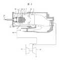
(1)拡散燃焼方式では、図2に示すように、燃焼器の頭部に設けた空気旋回器の出口付近に空気の旋回流と交差するように燃料を外側へ向けて噴出し、中心軸上にできる循環流によって拡散火炎を安定化するように図っている。 (1) In the diffusion combustion system, as shown in FIG. 2, fuel is ejected outward near the outlet of the air swirler provided at the head of the combustor so as to intersect the swirling flow of air, and the central axis It aims to stabilize the diffusion flame by the circulation flow that can be made above.
図2において、圧縮機10から送られる空気50は外筒2と燃焼器ライナ3の間を通り、一部は燃焼器ライナの冷却空気31及び燃焼ガスの混合を促す希釈空気32として燃焼室1へ、また一部は頭部旋回空気49として空気旋回器12を通り燃焼室1へ流入する。気体燃料16は拡散燃料ノズル13から旋回空気流に交差するように外側へ向けて燃焼室1に噴射され、頭部旋回空気49および1次燃焼用空気33とともに安定な拡散火炎4を形成する。発生した高温燃焼ガスはタービン18へ入り仕事をして排気される。 In FIG. 2, the
ここに示した拡散燃焼方式は、燃焼安定性が高い反面、燃料と酸素が量論比になる部分に火炎が形成され、火炎温度が断熱火炎温度に近い高温となる。窒素酸化物の生成速度が火炎温度上昇に対し指数関数的に増加するため、一般的に拡散燃焼では窒素酸化物の排出濃度が高く、大気汚染防止の観点から望ましくない。 Although the diffusion combustion system shown here has high combustion stability, a flame is formed in a portion where the fuel and oxygen have a stoichiometric ratio, and the flame temperature becomes a high temperature close to the adiabatic flame temperature. Since the generation rate of nitrogen oxides increases exponentially with an increase in flame temperature, the diffusion concentration of nitrogen oxides is generally high in diffusion combustion, which is undesirable from the viewpoint of preventing air pollution.
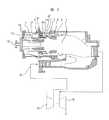
(2)一方、予混合燃焼方式は、低NOx化のために用いられる。図3は中心部を安定性に優れた拡散燃焼とし、外周側に低NOx性に優れた予混合燃焼を配して低NOx化を図った例である。図3において、圧縮機10から送られる空気50は外筒2と燃焼器ライナ3の間を通り、一部は燃焼器ライナの冷却空気31として燃焼室1へ、また一部は予混合燃焼用空気48として予混合器23へ流入する。残りは予混合器流路と燃焼器端板の間の通路を経て燃焼空気孔14と冷却空気孔17から燃焼室1へと流入する。拡散燃焼用の気体燃料16は拡散燃料ノズル13から燃焼室1に噴射され安定な拡散火炎4を形成する。予混合用気体燃料21は燃料ノズル8から環状の予混合器23内へと噴出して空気と混合して予混合気22となる。この予混合気22は燃焼室1へ流出し予混合火炎5を形成する。発生した高温燃焼ガスはタービン18へ入り仕事をして排気される。 (2) On the other hand, the premixed combustion method is used for reducing NOx. FIG. 3 shows an example in which NOx is reduced by using diffusion combustion with excellent stability at the center and premixed combustion with excellent low NOx performance on the outer peripheral side. In FIG. 3, the
しかし、このような予混合燃焼方式を採用した場合、予混合器内に火炎が入り込んで構造物を焼損する、いわゆる逆火現象が発生するなど予混合燃焼特有の不安定な要素を含んでいる。 However, when such a premixed combustion method is adopted, an unstable element peculiar to premixed combustion is included, such as a so-called flashback phenomenon in which a flame enters the premixer and burns out the structure. .
本発明の実施の形態では、燃料噴流と燃焼用空気流路を同軸上に配置し、燃料流を空気流が包み込むような同軸の噴流とするとともに、さらにそれらを多数に分散するように構成した多孔同軸噴流として燃焼室壁面に配置する。一方、一部またはすべての同軸噴流に対して、燃焼器の軸まわりに適度な旋回角をもって流入するように構成する。また、燃料の供給系統を複数に分割し、ガスタービンの起動,部分負荷運転時には、一部の系統のみに燃料を供給するように構成する。 In the embodiment of the present invention, the fuel jet and the combustion air flow path are arranged coaxially so that the fuel flow is a coaxial jet that wraps the air flow, and further, the fuel jet and the combustion air flow path are configured to be dispersed in a large number. It is arranged on the combustion chamber wall surface as a perforated coaxial jet. On the other hand, a part or all of the coaxial jets are configured to flow at an appropriate swirl angle around the combustor axis. In addition, the fuel supply system is divided into a plurality of parts, and the fuel is supplied to only a part of the system when the gas turbine is started and partially loaded.
燃料を空気流が包み込むような同軸の噴流とすることにより、燃料は燃焼室に流入した後、実際に高温ガスに接触して燃焼を開始する前に周囲の同軸空気流と混合し、適度な混合比の予混合気となったあと燃焼する。このため、希薄予混合燃焼と同等の低NOx燃焼が可能となる。このとき、従来の予混合燃焼器の予混合管に相当する部分が極めて短く、また壁面近傍で燃料濃度がほぼゼロとなるため逆火による焼損のポテンシャルも極めて低い。 By making the fuel into a coaxial jet that envelops the airflow, the fuel flows into the combustion chamber and then mixes with the surrounding coaxial airflow before actually in contact with the hot gas and starting combustion. It burns after it becomes a premixed gas mixture. For this reason, low NOx combustion equivalent to lean premixed combustion becomes possible. At this time, the portion corresponding to the premixing tube of the conventional premixing combustor is extremely short, and the fuel concentration is almost zero in the vicinity of the wall surface, so the potential for burnout due to flashback is extremely low.
また、一部またはすべての同軸噴流に対して、燃焼器の軸まわりに適度な旋回角をもって流入するように構成することで、同軸噴流という流れ形態ながら、同時に火炎を安定化するための再循環流を形成することができる。 In addition, recirculation for stabilizing the flame at the same time while forming a flow form of a coaxial jet by configuring it so that a part or all of the coaxial jet flows with an appropriate swirl angle around the axis of the combustor. A flow can be formed.
また、ガスタービンの起動,部分負荷運転時には、一部の系統のみに燃料を供給するようにすることで、局部的に燃料を過濃度の状態とし、周囲の空気中の酸素を利用する拡散燃焼に近い形で燃焼させることにより燃焼安定性を確保することができる。 In addition, when starting up gas turbines and under partial load operation, by supplying fuel to only some systems, the fuel is locally over-concentrated, and diffusion combustion that uses oxygen in the surrounding air Combustion stability can be ensured by burning in a form close to.
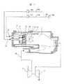
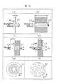
以下、本発明の実施例1を図1により説明する。図1において、圧縮機10から送られる空気50は、外筒2と燃焼器ライナ3の間を通る。その空気50の一部は、燃焼器ライナ3の冷却空気31として燃焼室1へ流入する。またその空気50の残りは、同軸空気51として空気孔52を通り燃焼室1へ流入する。 A first embodiment of the present invention will be described below with reference to FIG. In FIG. 1, the
燃料ノズル55および燃料ノズル56は、燃焼空気孔52の噴孔と同軸又は同軸に近い位置となるように配置されており、燃料53および燃料54は燃料ノズル55および燃料ノズル56から燃焼空気とほぼ同軸の噴流として燃焼室1に噴出し安定な火炎を形成する。発生した高温燃焼ガスは、タービン18へ入り仕事をして排気される。 The
本実施例では、燃料53および燃料54は、制御弁80aを備えた燃料供給系80が分割されている。つまり、ここでは、燃料供給系80が、第一の燃料供給系54bと、第二の燃料供給系53bの2つに分割されている。これら第一の燃料供給系54b及び第二の燃料供給系53bには夫々個別に単独で制御可能な制御弁53a及び制御弁54aが設けられている。これら制御弁53a及び制御弁54aは、ガスタービンの負荷によって夫々の燃料流量が独立に制御するように構成される。ここで、制御弁53aは、中央部の燃料ノズル群である燃料ノズル56群の流量が制御でき、制御弁54aは、周囲の燃料ノズル群である燃料ノズル55群の流量が制御できる。本実施例では中央部の燃料ノズル群とその周囲の燃料ノズル群とに複数に分割し、夫々に対応する燃料供給系統を設け、各々独立に燃料流量を制御できる前述した制御装置を備えている。 In the present embodiment, the
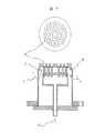
次に、図4を用いノズル部の詳細を説明する。本実施例では、燃料ノズル本体は中央の燃料ノズル56と周囲の燃料ノズル55に分かれている。これら燃料ノズル55及び燃料ノズル56の噴射方向前方側に、夫々に対応する空気孔52及び空気孔57が設けられている。これら空気孔52及び空気孔57は、円盤状部材に小径で複数設けられている。複数の燃料ノズル55及び燃料ノズル56に対応するよう複数の空気孔52及び空気孔57が設けられている。 Next, details of the nozzle portion will be described with reference to FIG. In this embodiment, the fuel nozzle body is divided into a
空気孔52及び空気孔57は、小径であるが、燃料ノズル55及び燃料ノズル56から噴射される燃料が空気孔52及び空気孔57を通過する際に、周囲の空気を伴って、燃料噴流とそれを包み込む空気の環状流が形成される程度の大きさとすることが望ましい。例えば、燃料ノズル55及び燃料ノズル56からの噴流径より若干大きくすることが望ましい。 The
空気孔52,空気孔57は、燃料ノズル55,燃料ノズル56と同軸噴流を形成するように配置されており、燃料噴流を空気環状流で包んだような多数の同軸噴流が空気孔52,空気孔57端面から噴出する。即ち、燃料ノズル55,燃料ノズル56の燃料噴孔が空気孔52や空気孔57と、同軸または同軸に近い位置に設置され、燃料噴流が空気孔52や空気孔57の入り口中心近傍に向けて噴出し、燃料噴流とそれを包み込む空気の環状流が同軸噴流となる。 The
燃料と空気が多数の小径の同軸噴流として構成されているので、これらの燃料と空気は短距離で混合させることができる。そのため、燃料の偏在もなく高い燃焼効率を保つことができる。 Since fuel and air are configured as a large number of small-diameter coaxial jets, these fuel and air can be mixed in a short distance. Therefore, high combustion efficiency can be maintained without uneven distribution of fuel.
また、本実施例の構成では燃料が空気孔の端面から噴出するまでに一部混合が進み、一層短い距離での燃料と空気の混合が期待できる。さらに、空気孔の流路長さを調節することにより、ほとんど流路内で混合しない状態からほぼ完全予混合の状態にまで設定することが可能である。 Further, in the configuration of the present embodiment, partial mixing proceeds until the fuel is ejected from the end face of the air hole, and mixing of fuel and air at a shorter distance can be expected. Furthermore, by adjusting the flow path length of the air hole, it is possible to set from a state of hardly mixing in the flow path to a state of almost complete premixing.
なお、本実施例では、中央の燃料ノズル56と中央の空気孔57には燃焼室軸周りの旋回がかかるように適当な旋回角が付与されている。このように対応する空気孔57に燃焼室軸周りに旋回する成分を与える旋回角を設けることにより、中央燃料を含む混合気流に旋回による安定な再循環領域が形成され、火炎を安定化することができる。 In this embodiment, an appropriate swirl angle is given to the
また、本実施例では、ガスタービンの種々の負荷条件に対して顕著な効果が期待できる。図1に示す制御弁53a及び制御弁54aを利用し燃料流量を調整してガスタービンの種々の負荷条件に対応できる。 In this embodiment, a remarkable effect can be expected for various load conditions of the gas turbine. The fuel flow rate is adjusted using the
つまり、ガスタービン負荷の小さい条件では、全空気量に対する燃料流量が小さくなるが、その場合には中央燃料53のみを供給し、中央領域での燃料濃度を火炎が安定に形成される濃度以上に保つように運用することができる。また、ガスタービン負荷の大きい条件では、中央の燃料53と周囲の燃料54の両方を供給して全体として希薄低NOx燃焼を行うことができる。また、中間的な負荷においては、中央の燃料53の量を空気孔57から流れる空気量に対して当量比が1を超えるような設定として、周囲の空気を燃焼に使う拡散燃焼的な運用することも可能である。 In other words, under conditions where the gas turbine load is small, the fuel flow rate with respect to the total air amount is small. In this case, only the
従って、種々のガスタービン負荷に応じて、火炎の安定化や低NOx燃焼に寄与できる。 Therefore, it can contribute to flame stabilization and low NOx combustion according to various gas turbine loads.
このように、燃料を空気流が包み込むような同軸の噴流とすることにより、燃料は燃焼室に流入した後、実際に高温ガスに接触して燃焼を開始する前に周囲の同軸空気流と混合し、適度な混合比の予混合気となったあと燃焼する。このため、希薄予混合燃焼と同等の低NOx燃焼が可能となる。このとき、本実施例では、従来の予混合燃焼器の予混合管に相当する部分が極めて短くできる。 In this way, by making the fuel jet into a coaxial jet that envelops the air flow, the fuel flows into the combustion chamber and then mixes with the surrounding coaxial air flow before actually contacting the hot gas and starting combustion. Then, after it becomes a premixed gas with an appropriate mixing ratio, it burns. For this reason, low NOx combustion equivalent to lean premixed combustion becomes possible. At this time, in this embodiment, the portion corresponding to the premixing tube of the conventional premixing combustor can be made extremely short.
また、壁面近傍で燃料濃度がほぼゼロとなるため、逆火による焼損のポテンシャルも極めて低い。 Moreover, since the fuel concentration is almost zero near the wall surface, the potential for burnout due to flashback is extremely low.
以上のように、本実施例によると、低NOxかつ燃焼安定性に優れたガスタービン燃焼器およびガスタービン燃焼器の運転方法を提供することができる。 As described above, according to the present embodiment, it is possible to provide a gas turbine combustor and a gas turbine combustor operating method that have low NOx and excellent combustion stability.
図5に実施例2のノズル部詳細を示す。本実施例では、燃料の系統が1つで中央と周囲とに分かれていない。また、中央付近のノズル,燃焼空気孔には旋回角が付与されていない。本実施例では、運用上、あるいは燃料の性状により燃焼安定性があまり問題とならないような状況の場合にノズル構造の簡素化が図れる。 FIG. 5 shows details of the nozzle portion of the second embodiment. In this embodiment, there is one fuel system and it is not divided into the center and the periphery. Further, the swivel angle is not given to the nozzle and the combustion air hole near the center. In this embodiment, the nozzle structure can be simplified in operation or in a situation where combustion stability is not a significant problem due to the properties of the fuel.
図6に実施例3を示す。本実施例では図5に示した実施例2のノズルを複数個組み合わせて一つの燃焼器を構成するようにしたものである。つまり、燃料ノズルと空気孔を一つのモジュールとしてこれらを複数個組み合わせて1つの燃焼器を構成している。 Example 3 is shown in FIG. In this embodiment, a single combustor is constituted by combining a plurality of nozzles of
このような構成とすることで、実施例1で説明したように燃料系統を複数化してガスタービンの負荷の変化に対して柔軟に対処できるとともに、ノズルの数の増減で燃焼器1缶あたりの容量の異なるものを比較的容易に提供できる。 By adopting such a configuration, as described in the first embodiment, it is possible to flexibly cope with a change in the load of the gas turbine by using a plurality of fuel systems and to increase / decrease the number of nozzles per can of the combustor. Those having different capacities can be provided relatively easily.
図7に実施例4を示す。本実施例では実施例2と基本的に同じであるが、空気旋回器58により同軸噴流自体に、旋回成分を持たせた点が異なる。 Example 4 is shown in FIG. The present embodiment is basically the same as the second embodiment except that the coaxial jet itself is provided with a swirl component by the
このように構成することにより、個々の同軸噴流の混合が促進され、より均一な低NOx燃焼が可能となる。燃料ノズル内に燃料噴流に旋回成分を与えるような構造も混合促進に有効である。 With this configuration, mixing of individual coaxial jets is promoted, and more uniform low NOx combustion is possible. A structure in which a swirl component is given to the fuel jet in the fuel nozzle is also effective for promoting mixing.
図8には実施例5を示す。本実施例では実施例3の中心軸に設置したノズルを空気旋回器63とこれに交差する燃料噴孔62を備える従来型の拡散バーナー61とした点が異なる。 FIG. 8 shows a fifth embodiment. This embodiment is different from the third embodiment in that the nozzle installed on the central axis of the third embodiment is a conventional diffusion burner 61 having an
このように構成することで従来の拡散燃焼バーナーを起動・昇速,部分負荷で使うことにより起動安定性を重視する場合有利と考えられる。 Such a configuration is considered advantageous when starting stability is emphasized by using a conventional diffusion combustion burner at start-up / acceleration and partial load.
図9には実施例6を示す。本実施例では、図8に示した実施例の拡散バーナー61の中に液体燃料ノズル68と噴霧空気ノズル69を設置し、液体燃料66を噴霧空気65で霧化して液体燃料の燃焼にも対応できるようにしたものである。低NOx化という点では多くは期待できないが、燃料の供給状況によっては柔軟な対応が可能な燃焼器を提供するものである。 FIG. 9 shows a sixth embodiment. In this embodiment, the liquid fuel nozzle 68 and the spray air nozzle 69 are installed in the diffusion burner 61 of the embodiment shown in FIG. 8, and the
図10には実施例7を示す。本実施例は図1および図4で示した第1の実施例に、燃焼器の下流側に補助的な燃料供給系71とヘッダー72,ノズル73を追加した例である。
ノズル73から噴出した燃料は空気孔74を通って同軸状の噴流となって燃焼室に流入し、上流側から流れてくる高温ガスにより燃焼反応が進む。FIG. 10 shows a seventh embodiment. This embodiment is an example in which an auxiliary fuel supply system 71, a
The fuel ejected from the
このような構成とすることにより、構造は複雑となるが、さらに、負荷対応が柔軟な低NOx燃焼器を提供できる。 By adopting such a configuration, the structure is complicated, but a low NOx combustor that is flexible in load handling can be provided.
図11には実施例8を示す。本実施例では図5に示した実施例の個々の燃料ノズルを2重構造化することにより、内側の液体燃料ノズル68には液体燃料66を供給し、外側のノズル81には噴霧空気65を供給することで液体燃料66を用いた場合にも多数の同軸噴流を形成して逆火ポテンシャルのきわめて小さい低NOx燃焼を実現することができる。 FIG. 11 shows an eighth embodiment. In this embodiment, the individual fuel nozzles of the embodiment shown in FIG. 5 are made into a double structure so that the
また、液体燃料の供給を止め、噴霧空気の代わりに気体燃料を供給することにより、気体燃料の低NOx燃焼器としても動作することが可能であり、液体と気体の両方の燃料に対応した燃焼器の提供が可能となる特徴も合わせ持つことができる。 In addition, by stopping the supply of liquid fuel and supplying gaseous fuel instead of atomizing air, it is possible to operate as a low-NOx combustor of gaseous fuel, and combustion corresponding to both liquid and gaseous fuel It can also have features that make it possible to provide vessels.
このように、燃料ノズルの一部またはすべてを二重構造として、液体燃料の噴霧と気体燃料を切り替えてまたは併用して使用できるようにしたことで、液体と気体の両方の燃料に対応できる。 As described above, a part or all of the fuel nozzles have a double structure so that the spraying of the liquid fuel and the gaseous fuel can be switched or used in combination, so that both liquid and gaseous fuels can be used.
以上のように、前述の実施例によると、燃料を空気流が包み込むような多数の同軸の噴流とすることにより、燃料は燃焼室に流入した後、実際に高温ガスに接触して燃焼を開始する前に周囲の同軸空気流と混合し、適度な混合比の予混合気となったあと燃焼する。このため、希薄予混合燃焼と同等の低NOx燃焼が可能となる。このとき、従来の予混合燃焼器の予混合管に相当する部分が極めて短く、また壁面近傍で燃料濃度がほぼゼロとなるため逆火による焼損のポテンシャルも極めて低い信頼性の高い燃焼器を提供できる。 As described above, according to the above-described embodiment, the fuel is flowed into the combustion chamber by making many coaxial jets that wrap the fuel in the air flow, and then actually comes into contact with the hot gas and starts combustion. Before mixing, it is mixed with the surrounding coaxial air flow, and after it becomes a premixed gas with an appropriate mixing ratio, it burns. For this reason, low NOx combustion equivalent to lean premixed combustion becomes possible. At this time, the part corresponding to the premixing tube of the conventional premixing combustor is extremely short, and the fuel concentration is almost zero near the wall surface. it can.
図12は、燃料ノズル55と燃焼空気孔52をほぼ同軸配置した部分断面図を示す。燃料ノズル55の燃料噴出下流側に燃焼空気孔52を設けている。つまり、燃料ノズル55の燃料噴出下流側に予混合流路が形成される。この燃焼空気孔52の大きさ(流路面積)は、燃料ノズル55の燃料噴出孔面積よりも大きく形成することが良い。本実施例では、燃焼空気孔52の直径(予混合流路直径面積)は、燃料ノズル55の燃料噴出孔直径(面積)よりも大きく形成されている。燃料ノズル55からこの予混合流路を介して燃料を噴出して、燃料と空気を同軸噴流している。この際、燃料ノズル55からの燃料は、燃焼空気孔52の入り口部のほぼ中心に向かって噴出し良好な同軸噴流を形成することが望ましい。また、本実施例の場合、空気出口下流の燃料濃度分布は図中に示すとおり同軸流の軸を中心に対称な形をしており、下流に行くに従い急速に混合し均一化していく。これにより従来の予混合燃焼方式に比べて、短い予混合距離で同等の低NOx性能を実現することができる。 FIG. 12 shows a partial cross-sectional view in which the
また、図13(a)及び図13(b)は、燃料ノズル55の燃料噴流軸に対して燃焼空気孔52の軸を角度θ°傾けて配置した例である。燃焼空気孔52の入り口付近では同軸状配置で、流れ方向に対して燃焼空気孔52を傾けたものである。このように配置した場合の空気出口下流の燃料濃度分布は、図中に示すように空気噴流軸に対して非対称な分布となる。下流に行くに従い混合して均一化するが軸に対する非対称性は完全には解消されず、濃度偏差が残ると考えられる。そして、例えば、図13(b)に示すように、同軸噴流の集合体で形成されるバーナの中心近くの同軸噴孔にこのような燃料噴流軸と空気孔軸のズレを積極的に利用することが考えられる。つまり、本実施例では、保炎領域周り,バーナ中心部付近に前述の燃焼空気孔52の傾きθ°を設け、反中心側の燃焼空気孔52を傾けずに(θ=0°)構成し、火炎保持領域の燃料濃度を比較的濃い状態に保ち、火炎の安定性を強化することができる。本実施例では燃料噴孔に旋回角や内向き・外向き角の無いストレートな燃料噴孔を採用しながら空気孔のみに旋回角などのバーナの軸と平行ではない角度を持たせることにより、比較的簡単な構造で予混合気に旋回や内向き・外向き角を付与することができ、バーナの構成・目的に応じて予混合気の流れを比較的簡単な構造で設定できる点で優れている。 FIGS. 13A and 13B are examples in which the axis of the
次に、図14は、燃料噴孔と空気孔の同軸配置の軸方向は同一で位置ずれdを意図的に設定した例である。このずれによって、図中に示すように空気噴流軸に対して濃度偏差は非対称な分布となり、燃料の濃度偏差を積極的に発生させることができ、燃焼安定性向上などの燃焼特性改善をはかることができる。 Next, FIG. 14 is an example in which the axial direction of the coaxial arrangement of the fuel injection hole and the air hole is the same and the positional deviation d is set intentionally. Due to this deviation, as shown in the figure, the concentration deviation is asymmetrically distributed with respect to the air jet axis, and the concentration deviation of the fuel can be positively generated, and combustion characteristics such as combustion stability can be improved. Can do.
このような本実施例では、予混合流路内で燃料ノズル55からの燃料は、ほぼ予混合流路中心に沿って流れる。また、燃料ノズル55の外周側から空気が予混合流路内でその流路外周側に沿って流れるよう構成している。そのため、予混合流路内では燃料の流れに沿ってその燃料流れの外周側を空気が流れ、両者の流れはほぼ同軸状となる。このようなノズル形態を複数設けることで、混合促進が図れ、簡易な構造で安定燃焼を実現可能となる。 In this embodiment, the fuel from the
また、図15(a)及び(b)には、予混合長さLの長短の例を示す。空気孔から出た後の急拡大による混合が支配的で、予混合長さLが混合の均一性、低NOx性能に与える影響はそれほど大きくないと考えられる。図15(a)のように空気孔を形成する部材を薄くして予混合距離Lを短くしても低NOx性能は十分に確保できると考えられる。一方、空気孔を形成する部材の材料や、空気孔の穴加工の加工費節約が期待できコスト低減が有利である。図15(b)には予混合長さLを十分長くとった場合の例を示す。燃料と空気がこの流路内で十分に混合することが期待でき、一層低NOx性に優れた燃焼器を提供できる。更に、空気孔に斜めの角度をつけて旋回成分を与えたり、内向き・外向きの偏向角を与えるなどの機能を付与する場合にもLが空気孔径の数倍程度あった方が有利である。 15A and 15B show examples of the length of the premixing length L. Mixing due to rapid expansion after exiting the air hole is dominant, and it is considered that the influence of the premixing length L on the uniformity of mixing and the low NOx performance is not so great. As shown in FIG. 15A, it is considered that the low NOx performance can be sufficiently ensured even if the member for forming the air hole is made thin and the premixing distance L is shortened. On the other hand, it is possible to expect savings in the material of the member forming the air holes and the processing cost of the hole processing of the air holes, and the cost reduction is advantageous. FIG. 15B shows an example where the premix length L is sufficiently long. Fuel and air can be expected to be sufficiently mixed in this flow path, and a combustor with even lower NOx properties can be provided. Furthermore, it is advantageous that L is about several times the diameter of the air hole in order to give a function such as giving a swirl component by giving an oblique angle to the air hole or giving an inward / outward deflection angle. is there.
図15(c)及び(d)には、燃料噴孔先端と空気孔入り口の軸方向距離Gが違う例を示す。図15(c)は、Gが大きい例で、実質的な予混合距離が長く取れ、混合の均一化,低NOx性について有利と考えられる。また、燃料ノズルの長さを短くできるため、燃料ノズルの製作性が向上し、コスト低減が図れる。一方、図15(d)は、相対的に燃料ノズル55の下流側に予混合流路を形成し、軸方向距離Gがマイナスで燃料噴孔が空気孔内に突き出した配置である。このような配置とすることにより、逆火のポテンシャルは一層低減され、ジメチルエーテル(DME)などの着火性の良い燃料を低NOxで燃焼させる場合などに有効であると考えられる。 FIGS. 15C and 15D show examples in which the axial distance G between the fuel nozzle tip and the air hole inlet is different. FIG. 15C is an example in which G is large. A substantial premixing distance can be taken, and it is considered advantageous for uniform mixing and low NOx properties. Further, since the length of the fuel nozzle can be shortened, the manufacturability of the fuel nozzle is improved and the cost can be reduced. On the other hand, FIG. 15 (d) shows an arrangement in which a premixing channel is formed relatively downstream of the
図15(e)及び(f)には、空気孔の直径Dの大きさが小さい例と大きい例である。
空気孔の直径Dが小さくその分、数を多く設置した図15(e)の場合は、燃料と空気がバーナから細かく分散して供給されるため、短い距離で均一に良く混合し、より低NOx性能を重視する場合に適している。図15(f)のように空気孔直径Dを大きくして空気孔の数を少なく配置する場合には、混合距離が長く必要で、均一性もやや損なわれるため低NOx性能はやや劣るが、製作工数の削減が図れるとともに要求される製作精度も比較的粗くでき、コスト低減に重点をおく場合に有利である。FIGS. 15E and 15F show an example in which the diameter D of the air hole is small and large.
In the case of FIG. 15 (e) in which the diameter D of the air hole is small and the number thereof is increased, the fuel and air are finely dispersed from the burner, so that they are uniformly mixed well in a short distance, and are lower. Suitable when NOx performance is important. When the air hole diameter D is increased and the number of air holes is reduced as shown in FIG. 15 (f), a long mixing distance is required and the uniformity is somewhat impaired, so the low NOx performance is slightly inferior. It is possible to reduce the number of manufacturing steps and to make the required manufacturing accuracy relatively rough, which is advantageous when emphasizing cost reduction.
図16(a)には他の実施例を示す。これまでに述べた実施例では同軸空気孔のバーナ面内の配置は同心円状に分散して配置する例を示してきたが、格子状配置や千鳥配置としても基本的な特性は失われるものではない。図16(a)はそのように配置する場合の例を示すものである。このように配置する場合、燃焼器ライナーでの平均流速にもよるが、火炎の形成される軸方向位置がライナー断面内でほぼ同一の浮き上がった火炎となる。製作する上では単純で良いが火炎の安定化という点では十分ではない場合もある。図16(b)はそのような場合に対して、バーナ面内の一部に、空気孔のピッチは同一でも空気孔の面積の小さな領域や、空気孔の無いまたはピッチの大きな領域などを設けて低流速部や循環流領域を形成し、この部分で火炎を安定化するようにした例である。このように構成することで逆火ポテンシャルが小さく、低NOx性と燃焼安定性を兼ね備えた燃焼器を提供できる。 FIG. 16A shows another embodiment. In the embodiment described so far, the arrangement of the coaxial air holes in the burner surface has been shown as being concentrically distributed, but the basic characteristics are not lost even in a lattice arrangement or a staggered arrangement. Absent. FIG. 16 (a) shows an example of such arrangement. When arranged in this manner, although depending on the average flow velocity in the combustor liner, the axial position in which the flame is formed becomes a substantially lifted flame within the liner cross section. It may be simple to produce but may not be sufficient in terms of flame stabilization. In FIG. 16B, in such a case, a part of the burner surface is provided with a region having a small air hole area or a region having no air hole or a large pitch even though the air hole pitch is the same. In this example, a low flow velocity portion and a circulation flow region are formed, and the flame is stabilized at this portion. Such a configuration can provide a combustor having a low flashback potential and having both low NOx properties and combustion stability.
図17に本発明の予混合距離LとNOx排出量の関係についての実験結果の一例を示す。燃料と空気を完全に混合したあと燃焼させる完全予混合燃焼では混合距離を十分長くとるか圧力損失の大きな混合デバイスが必要であるが、排出されるNOxは非常に低くなる。(図中A点)一方、環状の予混合流路に複数の燃料ノズルを配置して形成する実用的な予混合器構造においては予混合距離Lに概略逆比例でNOxが増加し、このような予混合器の一例のNOxを図中B点に示す。 FIG. 17 shows an example of an experimental result regarding the relationship between the premix distance L and the NOx emission amount of the present invention. Complete premix combustion, in which fuel and air are completely mixed and then combusted, requires a mixing device having a sufficiently long mixing distance or a large pressure loss, but the NOx discharged is very low. (Point A in the figure) On the other hand, in a practical premixer structure formed by arranging a plurality of fuel nozzles in an annular premixing flow path, NOx increases approximately in inverse proportion to the premixing distance L. An example of a premixer, NOx, is shown at point B in the figure.
これに対し、本発明では、燃料と空気を多数の同軸噴流として配置する本発明の一実施例の予混合距離とNOx排出量の関係は図中C点に示すとおりで、完全予混合燃焼には及ばないものの、従来構造の20分の1以下の予混合距離で従来の予混合器と同等のNOx性能を発揮することが示されている。 On the other hand, in the present invention, the relationship between the premix distance and the NOx emission amount in one embodiment of the present invention in which fuel and air are arranged as a large number of coaxial jets is as shown at point C in the figure. However, it has been shown that the NOx performance equivalent to that of the conventional premixer is exhibited at a premixing distance of 1/20 or less that of the conventional structure.
1…燃焼室、2…外筒、3…燃焼器ライナ、4…拡散火炎、5…予混合火炎、8,55,56…燃料ノズル、10…圧縮機、12,63…空気旋回器、13…拡散燃料ノズル、14…燃焼空気孔、16…気体燃料、17…冷却空気孔、18…タービン、21…予混合用気体燃料、22…予混合気、23…予混合器、31…冷却空気、32…希釈空気、33…1次燃焼用空気、49…頭部旋回空気、50…空気、51…同軸空気、52,57,74…空気孔、53,54…燃料、61…拡散バーナー、62…燃料噴孔、65…噴霧空気、66…液体燃料、68…液体燃料ノズル、69…噴霧空気ノズル、71,80…燃料供給系、72…ヘッダー、73…ノズル。 DESCRIPTION OF
Claims (5)
Translated fromJapanese前記燃焼室に気体燃料を噴出する複数の燃料ノズルと、
前記燃焼室の壁面に配置され、前記気体燃料と空気とを燃焼室に噴出するように複数の空気孔を有する部材とを備え、
燃料噴流とそれを包み込む空気の環状流が、前記燃料ノズルから噴出した前記気体燃料が前記空気孔を通過する際に形成され、前記空気孔を出た後に拡大するよう構成され、
前記燃焼室内に再循環流を形成し、前記再循環流に向かって、前記燃料ノズルからの燃料噴流とそれを包み込む空気の環状流が複数供給されるよう構成されていることを特徴とする燃焼器。A combustion chamber for mixing and burning fuel and air;
A plurality of fuel nozzles for ejecting gaseous fuel into the combustion chamber;
A member disposed on a wall surface of the combustion chamber, and having a plurality of air holes so as to eject the gaseous fuel and air into the combustion chamber ;
An annular flow of fuel jet and air enclosing it is formed when the gaseous fuel ejected from the fuel nozzle passes through the air hole, and is configured to expand after leaving the air hole,
Combustion characterized in that a recirculation flow is formed in the combustion chamber, and a plurality of fuel jets from the fuel nozzle and an annular flow of air surrounding the fuel nozzle are supplied toward the recirculation flow. vessel.
前記再循環流は、前記燃料ノズルと前記空気孔少なくとも一方に付与された旋回角により与えられた、前記燃焼室の軸周りに旋回する成分により形成されることを特徴とする燃焼器。The combustor of claim 1.
Before Symbol recycle stream combustor characterized by being formed by a component the fuel nozzle and the provided by an air hole at least one turning angle imparted to the pivots around the axis of the combustion chamber.
前記再循環流は、前記部材に設けられた空気孔のない領域または空気孔の面積の小さな領域に向かう流れであることを特徴とする燃焼器。The combustor of claim 2.
The combustor according to claim 1, wherein the recirculation flow is a flow toward a region without air holes or a region with a small area of air holes provided in the member.
前記部材に設けられた空気孔のない領域は、前記部材の中心に設けられていることを特徴とする燃焼器。The combustor of claim 3.
The combustor characterized in that the region without air holes provided in the member is provided in the center of the member.
前記燃焼室に気体燃料を噴出する複数の燃料ノズルと、
前記燃焼室の壁面に配置され、前記気体燃料と空気とを燃焼室に噴出するように複数の空気孔を有する部材とを備えた燃焼器の運転方法において、
燃料噴流とそれを包み込む空気の環状流を、前記燃料ノズルから噴出した燃料が前記空気孔を通過する際に形成し、前記空気孔から前記燃焼室に噴出させて拡大させ、
再循環流を形成するように空気及び燃料を前記燃焼室内に供給し、前記再循環流に向かって、燃料噴流とそれを包み込む空気の環状流を複数供給することを特徴とする燃焼器の運転方法。A combustion chamber for mixing and burning fuel and air;
A plurality of fuel nozzles for ejecting gaseous fuel into the combustion chamber;
In a method of operating a combustor, whichis disposed on a wall surface of the combustion chamber and includes amember having a plurality of air holes so as to eject the gaseous fuel and air into the combustion chamber .
A fuel jet and an annular flow of air enclosing it are formed when the fuel jetted from the fuel nozzle passes through the air holes, and are blown out from the air holes into the combustion chamber to be expanded,
Combustor operation characterized in that air and fuel are supplied into the combustion chamber so as to form a recirculation flow, and a plurality of fuel jets and an annular flow of air enclosing it are supplied toward the recirculation flow. Method.
Priority Applications (1)
| Application Number | Priority Date | Filing Date | Title |
|---|---|---|---|
| JP2010094596AJP4998581B2 (en) | 2001-08-29 | 2010-04-16 | Gas turbine combustor and method of operating gas turbine combustor |
Applications Claiming Priority (3)
| Application Number | Priority Date | Filing Date | Title |
|---|---|---|---|
| JP2001259119 | 2001-08-29 | ||
| JP2001259119 | 2001-08-29 | ||
| JP2010094596AJP4998581B2 (en) | 2001-08-29 | 2010-04-16 | Gas turbine combustor and method of operating gas turbine combustor |
Related Parent Applications (1)
| Application Number | Title | Priority Date | Filing Date |
|---|---|---|---|
| JP2009012467ADivisionJP2009079893A (en) | 2001-08-29 | 2009-01-23 | Gas turbine combustor and method of operating gas turbine combustor |
Publications (2)
| Publication Number | Publication Date |
|---|---|
| JP2010156350A JP2010156350A (en) | 2010-07-15 |
| JP4998581B2true JP4998581B2 (en) | 2012-08-15 |
Family
ID=19086541
Family Applications (2)
| Application Number | Title | Priority Date | Filing Date |
|---|---|---|---|
| JP2009012467APendingJP2009079893A (en) | 2001-08-29 | 2009-01-23 | Gas turbine combustor and method of operating gas turbine combustor |
| JP2010094596AExpired - LifetimeJP4998581B2 (en) | 2001-08-29 | 2010-04-16 | Gas turbine combustor and method of operating gas turbine combustor |
Family Applications Before (1)
| Application Number | Title | Priority Date | Filing Date |
|---|---|---|---|
| JP2009012467APendingJP2009079893A (en) | 2001-08-29 | 2009-01-23 | Gas turbine combustor and method of operating gas turbine combustor |
Country Status (5)
| Country | Link |
|---|---|
| US (4) | US6813889B2 (en) |
| EP (3) | EP1843099B1 (en) |
| JP (2) | JP2009079893A (en) |
| CN (1) | CN1157563C (en) |
| DE (1) | DE60216206T2 (en) |
Families Citing this family (202)
| Publication number | Priority date | Publication date | Assignee | Title |
|---|---|---|---|---|
| US6813889B2 (en)* | 2001-08-29 | 2004-11-09 | Hitachi, Ltd. | Gas turbine combustor and operating method thereof |
| DE10160997A1 (en) | 2001-12-12 | 2003-07-03 | Rolls Royce Deutschland | Lean premix burner for a gas turbine and method for operating a lean premix burner |
| US6962055B2 (en)* | 2002-09-27 | 2005-11-08 | United Technologies Corporation | Multi-point staging strategy for low emission and stable combustion |
| US20090217669A1 (en)* | 2003-02-05 | 2009-09-03 | Young Kenneth J | Fuel nozzles |
| GB0302721D0 (en)* | 2003-02-05 | 2003-03-12 | Rolls Royce Plc | Fuel nozzles |
| US7546740B2 (en) | 2004-05-11 | 2009-06-16 | United Technologies Corporation | Nozzle |
| JP4626251B2 (en)* | 2004-10-06 | 2011-02-02 | 株式会社日立製作所 | Combustor and combustion method of combustor |
| JP4509742B2 (en)* | 2004-11-04 | 2010-07-21 | 株式会社日立製作所 | Gas turbine power generation equipment |
| US20080229749A1 (en)* | 2005-03-04 | 2008-09-25 | Michel Gamil Rabbat | Plug in rabbat engine |
| US20060196189A1 (en)* | 2005-03-04 | 2006-09-07 | Rabbat Michel G | Rabbat engine |
| ES2356355T3 (en) | 2005-04-12 | 2011-04-07 | Zilkha Biomass Energy Llc | BIOMASS INTEGRATED ENERGY SYSTEM. |
| US20070204624A1 (en)* | 2006-03-01 | 2007-09-06 | Smith Kenneth O | Fuel injector for a turbine engine |
| JP5046194B2 (en) | 2006-08-07 | 2012-10-10 | 日本電気株式会社 | MRAM with variable word line drive potential |
| CA2642303A1 (en)* | 2006-09-29 | 2008-07-31 | Zilkha Biomass Energy Llc | Integrated biomass energy system |
| US20080092544A1 (en)* | 2006-10-18 | 2008-04-24 | Lean Flame, Inc. | Premixer for gas and fuel for use in combination with energy release/conversion device |
| US7937945B2 (en) | 2006-10-27 | 2011-05-10 | Kinde Sr Ronald August | Combining a series of more efficient engines into a unit, or modular units |
| JP4466667B2 (en)* | 2007-03-19 | 2010-05-26 | 株式会社日立製作所 | High-humidity air-utilizing gas turbine, control device for high-humidity air-utilizing gas turbine, and control method for high-humidity air-utilizing gas turbine |
| JP2008261605A (en)* | 2007-04-13 | 2008-10-30 | Mitsubishi Heavy Ind Ltd | Gas turbine combustor |
| JP4959620B2 (en)* | 2007-04-26 | 2012-06-27 | 株式会社日立製作所 | Combustor and fuel supply method for combustor |
| EP1985920B1 (en)* | 2007-04-26 | 2019-04-10 | Mitsubishi Hitachi Power Systems, Ltd. | Combustor and a fuel suppy method for the combustor |
| US20080268387A1 (en)* | 2007-04-26 | 2008-10-30 | Takeo Saito | Combustion equipment and burner combustion method |
| GB2449267A (en)* | 2007-05-15 | 2008-11-19 | Alstom Technology Ltd | Cool diffusion flame combustion |
| JP4906689B2 (en)* | 2007-11-29 | 2012-03-28 | 株式会社日立製作所 | Burner, combustion device, and method for modifying combustion device |
| US8042339B2 (en)* | 2008-03-12 | 2011-10-25 | General Electric Company | Lean direct injection combustion system |
| DE102008015577A1 (en)* | 2008-03-18 | 2009-10-22 | Deutsches Zentrum für Luft- und Raumfahrt e.V. | Method for low-emission combustion with liquid fuel and combustion chamber device |
| EP2276559A4 (en) | 2008-03-28 | 2017-10-18 | Exxonmobil Upstream Research Company | Low emission power generation and hydrocarbon recovery systems and methods |
| WO2009120779A2 (en) | 2008-03-28 | 2009-10-01 | Exxonmobil Upstream Research Company | Low emission power generation and hydrocarbon recovery systems and methods |
| JP5115372B2 (en)* | 2008-07-11 | 2013-01-09 | トヨタ自動車株式会社 | Operation control device for gas turbine |
| JP2010060189A (en)* | 2008-09-03 | 2010-03-18 | Hitachi Ltd | Burner, and method for supplying fuel and method for modifying fuel nozzle in burner |
| JP4872992B2 (en)* | 2008-09-12 | 2012-02-08 | 株式会社日立製作所 | Combustor, fuel supply method for combustor, and modification method for combustor |
| EA026915B1 (en) | 2008-10-14 | 2017-05-31 | Эксонмобил Апстрим Рисерч Компани | Methods and systems for controlling the products of combustion |
| US8327642B2 (en)* | 2008-10-21 | 2012-12-11 | General Electric Company | Multiple tube premixing device |
| US9822649B2 (en) | 2008-11-12 | 2017-11-21 | General Electric Company | Integrated combustor and stage 1 nozzle in a gas turbine and method |
| EP2189720A1 (en)* | 2008-11-21 | 2010-05-26 | Siemens Aktiengesellschaft | Burner assembly |
| US8297059B2 (en)* | 2009-01-22 | 2012-10-30 | General Electric Company | Nozzle for a turbomachine |
| US9140454B2 (en) | 2009-01-23 | 2015-09-22 | General Electric Company | Bundled multi-tube nozzle for a turbomachine |
| US8763399B2 (en)* | 2009-04-03 | 2014-07-01 | Hitachi, Ltd. | Combustor having modified spacing of air blowholes in an air blowhole plate |
| US8161751B2 (en)* | 2009-04-30 | 2012-04-24 | General Electric Company | High volume fuel nozzles for a turbine engine |
| WO2010128882A1 (en)* | 2009-05-07 | 2010-11-11 | General Electric Company | Multi-premixer fuel nozzle |
| JP5663023B2 (en) | 2009-09-13 | 2015-02-04 | リーン フレイム インコーポレイテッド | Inlet premixer for combustion equipment |
| JP5103454B2 (en)* | 2009-09-30 | 2012-12-19 | 株式会社日立製作所 | Combustor |
| JP5159741B2 (en)* | 2009-09-30 | 2013-03-13 | 株式会社日立製作所 | Control device for gas turbine combustor and control method for gas turbine combustor |
| US8402763B2 (en)* | 2009-10-26 | 2013-03-26 | General Electric Company | Combustor headend guide vanes to reduce flow maldistribution into multi-nozzle arrangement |
| EP2499332B1 (en) | 2009-11-12 | 2017-05-24 | Exxonmobil Upstream Research Company | Integrated system for power generation and method for low emission hydrocarbon recovery with power generation |
| US20110131998A1 (en)* | 2009-12-08 | 2011-06-09 | Vaibhav Nadkarni | Fuel injection in secondary fuel nozzle |
| US20110162375A1 (en)* | 2010-01-05 | 2011-07-07 | General Electric Company | Secondary Combustion Fuel Supply Systems |
| JP5084847B2 (en)* | 2010-01-13 | 2012-11-28 | 株式会社日立製作所 | Gas turbine combustor |
| EP2362143B1 (en)* | 2010-02-19 | 2012-08-29 | Siemens Aktiengesellschaft | Burner assembly |
| EP2362142A1 (en)* | 2010-02-19 | 2011-08-31 | Siemens Aktiengesellschaft | Burner assembly |
| US20110289929A1 (en)* | 2010-05-28 | 2011-12-01 | General Electric Company | Turbomachine fuel nozzle |
| MY156099A (en)* | 2010-07-02 | 2016-01-15 | Exxonmobil Upstream Res Co | Systems and methods for controlling combustion of a fuel |
| CA2801492C (en) | 2010-07-02 | 2017-09-26 | Exxonmobil Upstream Research Company | Stoichiometric combustion with exhaust gas recirculation and direct contact cooler |
| CN102971508B (en) | 2010-07-02 | 2016-06-01 | 埃克森美孚上游研究公司 | CO2 separation system and method for separating CO2 |
| TWI564475B (en) | 2010-07-02 | 2017-01-01 | 艾克頌美孚上游研究公司 | Low emission triple-cycle power generation systems and methods |
| MX354587B (en) | 2010-07-02 | 2018-03-12 | Exxonmobil Upstream Res Company Star | Stoichiometric combustion of enriched air with exhaust gas recirculation. |
| US8261555B2 (en)* | 2010-07-08 | 2012-09-11 | General Electric Company | Injection nozzle for a turbomachine |
| US8733108B2 (en)* | 2010-07-09 | 2014-05-27 | General Electric Company | Combustor and combustor screech mitigation methods |
| US20120015311A1 (en)* | 2010-07-14 | 2012-01-19 | Dawson Robert W | Burner for a gas combustor and a method of operating the burner thereof |
| US9334808B2 (en) | 2010-08-05 | 2016-05-10 | Mitsubishi Hitachi Power Systems, Ltd. | Combustor and the method of fuel supply and converting fuel nozzle for advanced humid air turbine |
| US8800289B2 (en)* | 2010-09-08 | 2014-08-12 | General Electric Company | Apparatus and method for mixing fuel in a gas turbine nozzle |
| US8707672B2 (en)* | 2010-09-10 | 2014-04-29 | General Electric Company | Apparatus and method for cooling a combustor cap |
| US8776529B2 (en)* | 2010-09-27 | 2014-07-15 | Hamilton Sundstrand Corporation | Critical flow nozzle for controlling fuel distribution and burner stability |
| US8991187B2 (en) | 2010-10-11 | 2015-03-31 | General Electric Company | Combustor with a lean pre-nozzle fuel injection system |
| JP5546432B2 (en)* | 2010-11-30 | 2014-07-09 | 株式会社日立製作所 | Gas turbine combustor and fuel supply method |
| US9488105B2 (en)* | 2010-12-01 | 2016-11-08 | Siemens Aktiengesellschaft | Gas turbine assembly and method therefor |
| US20120180487A1 (en)* | 2011-01-19 | 2012-07-19 | General Electric Company | System for flow control in multi-tube fuel nozzle |
| JP5470662B2 (en) | 2011-01-27 | 2014-04-16 | 株式会社日立製作所 | Gas turbine combustor |
| US8875516B2 (en)* | 2011-02-04 | 2014-11-04 | General Electric Company | Turbine combustor configured for high-frequency dynamics mitigation and related method |
| TWI563165B (en) | 2011-03-22 | 2016-12-21 | Exxonmobil Upstream Res Co | Power generation system and method for generating power |
| TWI593872B (en) | 2011-03-22 | 2017-08-01 | 艾克頌美孚上游研究公司 | Integrated system and method of generating power |
| TWI564474B (en) | 2011-03-22 | 2017-01-01 | 艾克頌美孚上游研究公司 | Integrated systems for controlling stoichiometric combustion in turbine systems and methods of generating power using the same |
| TWI563166B (en) | 2011-03-22 | 2016-12-21 | Exxonmobil Upstream Res Co | Integrated generation systems and methods for generating power |
| US8893501B2 (en)* | 2011-03-28 | 2014-11-25 | General Eletric Company | Combustor crossfire tube |
| FR2976649B1 (en)* | 2011-06-20 | 2015-01-23 | Turbomeca | FUEL INJECTION METHOD IN A COMBUSTION CHAMBER OF A GAS TURBINE AND INJECTION SYSTEM FOR ITS IMPLEMENTATION |
| EP2551470A1 (en)* | 2011-07-26 | 2013-01-30 | Siemens Aktiengesellschaft | Method for starting a stationary gas turbine |
| JP5438727B2 (en)* | 2011-07-27 | 2014-03-12 | 株式会社日立製作所 | Combustor, burner and gas turbine |
| US8966906B2 (en)* | 2011-09-28 | 2015-03-03 | General Electric Company | System for supplying pressurized fluid to a cap assembly of a gas turbine combustor |
| US20130081397A1 (en)* | 2011-10-04 | 2013-04-04 | Brandon Taylor Overby | Forward casing with a circumferential sloped surface and a combustor assembly including same |
| US9033699B2 (en)* | 2011-11-11 | 2015-05-19 | General Electric Company | Combustor |
| US9810050B2 (en) | 2011-12-20 | 2017-11-07 | Exxonmobil Upstream Research Company | Enhanced coal-bed methane production |
| US9134023B2 (en)* | 2012-01-06 | 2015-09-15 | General Electric Company | Combustor and method for distributing fuel in the combustor |
| JP5452634B2 (en)* | 2012-01-06 | 2014-03-26 | 株式会社日立製作所 | Fuel control method and fuel control apparatus for gas turbine combustor installed in gas turbine using high humidity air |
| JP5458121B2 (en)* | 2012-01-27 | 2014-04-02 | 株式会社日立製作所 | Gas turbine combustor and method of operating gas turbine combustor |
| US20130196270A1 (en)* | 2012-01-30 | 2013-08-01 | General Electric Company | Jet micro-induced flow reversals combustor |
| US20130199189A1 (en)* | 2012-02-08 | 2013-08-08 | Jong Ho Uhm | Fuel injection assembly for use in turbine engines and method of assembling same |
| US9353682B2 (en) | 2012-04-12 | 2016-05-31 | General Electric Company | Methods, systems and apparatus relating to combustion turbine power plants with exhaust gas recirculation |
| US10273880B2 (en) | 2012-04-26 | 2019-04-30 | General Electric Company | System and method of recirculating exhaust gas for use in a plurality of flow paths in a gas turbine engine |
| US9784185B2 (en) | 2012-04-26 | 2017-10-10 | General Electric Company | System and method for cooling a gas turbine with an exhaust gas provided by the gas turbine |
| US9534781B2 (en)* | 2012-05-10 | 2017-01-03 | General Electric Company | System and method having multi-tube fuel nozzle with differential flow |
| US9267690B2 (en) | 2012-05-29 | 2016-02-23 | General Electric Company | Turbomachine combustor nozzle including a monolithic nozzle component and method of forming the same |
| US20130318976A1 (en)* | 2012-05-29 | 2013-12-05 | General Electric Company | Turbomachine combustor nozzle and method of forming the same |
| JP5911387B2 (en)* | 2012-07-06 | 2016-04-27 | 三菱日立パワーシステムズ株式会社 | Gas turbine combustor and gas turbine combustor operating method |
| JP5908361B2 (en)* | 2012-07-24 | 2016-04-26 | 三菱日立パワーシステムズ株式会社 | Gas turbine combustor |
| JP5889754B2 (en)* | 2012-09-05 | 2016-03-22 | 三菱日立パワーシステムズ株式会社 | Gas turbine combustor |
| JP5908379B2 (en) | 2012-09-24 | 2016-04-26 | 三菱日立パワーシステムズ株式会社 | Gas turbine combustor |
| US10215412B2 (en) | 2012-11-02 | 2019-02-26 | General Electric Company | System and method for load control with diffusion combustion in a stoichiometric exhaust gas recirculation gas turbine system |
| US9631815B2 (en) | 2012-12-28 | 2017-04-25 | General Electric Company | System and method for a turbine combustor |
| US9803865B2 (en) | 2012-12-28 | 2017-10-31 | General Electric Company | System and method for a turbine combustor |
| US10161312B2 (en) | 2012-11-02 | 2018-12-25 | General Electric Company | System and method for diffusion combustion with fuel-diluent mixing in a stoichiometric exhaust gas recirculation gas turbine system |
| US9611756B2 (en) | 2012-11-02 | 2017-04-04 | General Electric Company | System and method for protecting components in a gas turbine engine with exhaust gas recirculation |
| US9869279B2 (en) | 2012-11-02 | 2018-01-16 | General Electric Company | System and method for a multi-wall turbine combustor |
| US9708977B2 (en) | 2012-12-28 | 2017-07-18 | General Electric Company | System and method for reheat in gas turbine with exhaust gas recirculation |
| US9574496B2 (en) | 2012-12-28 | 2017-02-21 | General Electric Company | System and method for a turbine combustor |
| US9599070B2 (en) | 2012-11-02 | 2017-03-21 | General Electric Company | System and method for oxidant compression in a stoichiometric exhaust gas recirculation gas turbine system |
| US10107495B2 (en) | 2012-11-02 | 2018-10-23 | General Electric Company | Gas turbine combustor control system for stoichiometric combustion in the presence of a diluent |
| EP2923150B1 (en)* | 2012-11-21 | 2018-09-05 | General Electric Company | Anti-coking liquid fuel cartridge |
| US9182125B2 (en)* | 2012-11-27 | 2015-11-10 | General Electric Company | Fuel plenum annulus |
| US9291103B2 (en)* | 2012-12-05 | 2016-03-22 | General Electric Company | Fuel nozzle for a combustor of a gas turbine engine |
| US10208677B2 (en) | 2012-12-31 | 2019-02-19 | General Electric Company | Gas turbine load control system |
| US9581081B2 (en) | 2013-01-13 | 2017-02-28 | General Electric Company | System and method for protecting components in a gas turbine engine with exhaust gas recirculation |
| US9512759B2 (en) | 2013-02-06 | 2016-12-06 | General Electric Company | System and method for catalyst heat utilization for gas turbine with exhaust gas recirculation |
| US9938861B2 (en) | 2013-02-21 | 2018-04-10 | Exxonmobil Upstream Research Company | Fuel combusting method |
| TW201502356A (en) | 2013-02-21 | 2015-01-16 | Exxonmobil Upstream Res Co | Reducing oxygen in a gas turbine exhaust |
| WO2014133406A1 (en) | 2013-02-28 | 2014-09-04 | General Electric Company | System and method for a turbine combustor |
| US9618261B2 (en) | 2013-03-08 | 2017-04-11 | Exxonmobil Upstream Research Company | Power generation and LNG production |
| US20140250945A1 (en) | 2013-03-08 | 2014-09-11 | Richard A. Huntington | Carbon Dioxide Recovery |
| CA2902479C (en) | 2013-03-08 | 2017-11-07 | Exxonmobil Upstream Research Company | Power generation and methane recovery from methane hydrates |
| TW201500635A (en) | 2013-03-08 | 2015-01-01 | Exxonmobil Upstream Res Co | Processing exhaust for use in enhanced oil recovery |
| EP2975325B1 (en)* | 2013-03-13 | 2019-05-08 | Mitsubishi Hitachi Power Systems, Ltd. | Gas turbine combustor |
| US9383104B2 (en)* | 2013-03-18 | 2016-07-05 | General Electric Company | Continuous combustion liner for a combustor of a gas turbine |
| US9617914B2 (en) | 2013-06-28 | 2017-04-11 | General Electric Company | Systems and methods for monitoring gas turbine systems having exhaust gas recirculation |
| TWI654368B (en) | 2013-06-28 | 2019-03-21 | 美商艾克頌美孚上游研究公司 | System, method and media for controlling exhaust gas flow in an exhaust gas recirculation gas turbine system |
| US9835089B2 (en) | 2013-06-28 | 2017-12-05 | General Electric Company | System and method for a fuel nozzle |
| US9631542B2 (en) | 2013-06-28 | 2017-04-25 | General Electric Company | System and method for exhausting combustion gases from gas turbine engines |
| US9903588B2 (en)* | 2013-07-30 | 2018-02-27 | General Electric Company | System and method for barrier in passage of combustor of gas turbine engine with exhaust gas recirculation |
| US9587510B2 (en) | 2013-07-30 | 2017-03-07 | General Electric Company | System and method for a gas turbine engine sensor |
| US9951658B2 (en) | 2013-07-31 | 2018-04-24 | General Electric Company | System and method for an oxidant heating system |
| US9920927B2 (en)* | 2013-08-13 | 2018-03-20 | Haul-All Equipment Ltd. | Low NOx burner |
| JP6190670B2 (en)* | 2013-08-30 | 2017-08-30 | 三菱日立パワーシステムズ株式会社 | Gas turbine combustion system |
| JP6210810B2 (en)* | 2013-09-20 | 2017-10-11 | 三菱日立パワーシステムズ株式会社 | Dual fuel fired gas turbine combustor |
| JP2015083779A (en)* | 2013-10-25 | 2015-04-30 | 三菱日立パワーシステムズ株式会社 | Gas turbine combustor and gas turbine combustor control method |
| JP6239943B2 (en) | 2013-11-13 | 2017-11-29 | 三菱日立パワーシステムズ株式会社 | Gas turbine combustor |
| JP6228434B2 (en) | 2013-11-15 | 2017-11-08 | 三菱日立パワーシステムズ株式会社 | Gas turbine combustor |
| US9752458B2 (en) | 2013-12-04 | 2017-09-05 | General Electric Company | System and method for a gas turbine engine |
| US10030588B2 (en) | 2013-12-04 | 2018-07-24 | General Electric Company | Gas turbine combustor diagnostic system and method |
| CN103727527A (en)* | 2014-01-02 | 2014-04-16 | 北京建筑大学 | High-power practical gas catalytic combustion kiln |
| US10227920B2 (en) | 2014-01-15 | 2019-03-12 | General Electric Company | Gas turbine oxidant separation system |
| US9863267B2 (en) | 2014-01-21 | 2018-01-09 | General Electric Company | System and method of control for a gas turbine engine |
| US9915200B2 (en) | 2014-01-21 | 2018-03-13 | General Electric Company | System and method for controlling the combustion process in a gas turbine operating with exhaust gas recirculation |
| US10079564B2 (en) | 2014-01-27 | 2018-09-18 | General Electric Company | System and method for a stoichiometric exhaust gas recirculation gas turbine system |
| US11384939B2 (en)* | 2014-04-21 | 2022-07-12 | Southwest Research Institute | Air-fuel micromix injector having multibank ports for adaptive cooling of high temperature combustor |
| US10047633B2 (en) | 2014-05-16 | 2018-08-14 | General Electric Company | Bearing housing |
| US10655542B2 (en) | 2014-06-30 | 2020-05-19 | General Electric Company | Method and system for startup of gas turbine system drive trains with exhaust gas recirculation |
| US9885290B2 (en) | 2014-06-30 | 2018-02-06 | General Electric Company | Erosion suppression system and method in an exhaust gas recirculation gas turbine system |
| US10060359B2 (en) | 2014-06-30 | 2018-08-28 | General Electric Company | Method and system for combustion control for gas turbine system with exhaust gas recirculation |
| JP6301774B2 (en)* | 2014-08-01 | 2018-03-28 | 三菱日立パワーシステムズ株式会社 | Gas turbine combustor |
| JP6262616B2 (en) | 2014-08-05 | 2018-01-17 | 三菱日立パワーシステムズ株式会社 | Gas turbine combustor |
| US20160053681A1 (en)* | 2014-08-20 | 2016-02-25 | General Electric Company | Liquid fuel combustor having an oxygen-depleted gas (odg) injection system for a gas turbomachine |
| JP6440433B2 (en)* | 2014-09-29 | 2018-12-19 | 川崎重工業株式会社 | Fuel injection nozzle, fuel injection module, and gas turbine |
| US9869247B2 (en) | 2014-12-31 | 2018-01-16 | General Electric Company | Systems and methods of estimating a combustion equivalence ratio in a gas turbine with exhaust gas recirculation |
| US9819292B2 (en) | 2014-12-31 | 2017-11-14 | General Electric Company | Systems and methods to respond to grid overfrequency events for a stoichiometric exhaust recirculation gas turbine |
| US10788212B2 (en) | 2015-01-12 | 2020-09-29 | General Electric Company | System and method for an oxidant passageway in a gas turbine system with exhaust gas recirculation |
| US10316746B2 (en) | 2015-02-04 | 2019-06-11 | General Electric Company | Turbine system with exhaust gas recirculation, separation and extraction |
| US10094566B2 (en) | 2015-02-04 | 2018-10-09 | General Electric Company | Systems and methods for high volumetric oxidant flow in gas turbine engine with exhaust gas recirculation |
| US10253690B2 (en) | 2015-02-04 | 2019-04-09 | General Electric Company | Turbine system with exhaust gas recirculation, separation and extraction |
| US10267270B2 (en) | 2015-02-06 | 2019-04-23 | General Electric Company | Systems and methods for carbon black production with a gas turbine engine having exhaust gas recirculation |
| US10145269B2 (en) | 2015-03-04 | 2018-12-04 | General Electric Company | System and method for cooling discharge flow |
| US10480792B2 (en) | 2015-03-06 | 2019-11-19 | General Electric Company | Fuel staging in a gas turbine engine |
| DE102015205069B4 (en)* | 2015-03-20 | 2020-04-23 | Deutsches Zentrum für Luft- und Raumfahrt e.V. | Incinerator |
| JP6423760B2 (en)* | 2015-06-24 | 2018-11-14 | 三菱日立パワーシステムズ株式会社 | Fuel nozzle structure of gas turbine combustor |
| JP6399458B2 (en)* | 2015-09-14 | 2018-10-03 | 大陽日酸株式会社 | Oxygen burner and method of operating oxygen burner |
| CN105090938A (en)* | 2015-09-14 | 2015-11-25 | 中国能源建设集团广东省电力设计研究院有限公司 | Fuel processing and supplying method of multi-fuel fuel machine |
| JP6484546B2 (en) | 2015-11-13 | 2019-03-13 | 三菱日立パワーシステムズ株式会社 | Gas turbine combustor |
| RU2015156419A (en) | 2015-12-28 | 2017-07-04 | Дженерал Электрик Компани | The fuel injector assembly made with a flame stabilizer pre-mixed mixture |
| US11428413B2 (en)* | 2016-03-25 | 2022-08-30 | General Electric Company | Fuel injection module for segmented annular combustion system |
| JP6633982B2 (en)* | 2016-07-01 | 2020-01-22 | 三菱日立パワーシステムズ株式会社 | Gas turbine combustor and method for manufacturing fuel nozzle of gas turbine combustor |
| US10465909B2 (en) | 2016-11-04 | 2019-11-05 | General Electric Company | Mini mixing fuel nozzle assembly with mixing sleeve |
| US10352569B2 (en) | 2016-11-04 | 2019-07-16 | General Electric Company | Multi-point centerbody injector mini mixing fuel nozzle assembly |
| US10724740B2 (en) | 2016-11-04 | 2020-07-28 | General Electric Company | Fuel nozzle assembly with impingement purge |
| US10295190B2 (en) | 2016-11-04 | 2019-05-21 | General Electric Company | Centerbody injector mini mixer fuel nozzle assembly |
| US10393382B2 (en) | 2016-11-04 | 2019-08-27 | General Electric Company | Multi-point injection mini mixing fuel nozzle assembly |
| US10634353B2 (en) | 2017-01-12 | 2020-04-28 | General Electric Company | Fuel nozzle assembly with micro channel cooling |
| US10982593B2 (en)* | 2017-06-16 | 2021-04-20 | General Electric Company | System and method for combusting liquid fuel in a gas turbine combustor with staged combustion |
| TWI725268B (en)* | 2017-12-15 | 2021-04-21 | 潔醇事業股份有限公司 | Jet burner |
| JP6945468B2 (en)* | 2018-02-06 | 2021-10-06 | 三菱パワー株式会社 | Control method of gas turbine combustor, gas turbine and gas turbine combustor |
| US10890329B2 (en) | 2018-03-01 | 2021-01-12 | General Electric Company | Fuel injector assembly for gas turbine engine |
| JP7044669B2 (en)* | 2018-09-05 | 2022-03-30 | 三菱重工業株式会社 | Gas turbine combustor |
| JP7193962B2 (en)* | 2018-09-26 | 2022-12-21 | 三菱重工業株式会社 | Combustor and gas turbine equipped with the same |
| US10935245B2 (en) | 2018-11-20 | 2021-03-02 | General Electric Company | Annular concentric fuel nozzle assembly with annular depression and radial inlet ports |
| CN109357287A (en)* | 2018-11-21 | 2019-02-19 | 贵州智慧能源科技有限公司 | Segmented rocket engine combustion chamber and power drive unit |
| CN109781422B (en)* | 2018-12-09 | 2021-01-12 | 西安航天动力试验技术研究所 | Wide-range simulated incoming flow heating device |
| US11286884B2 (en) | 2018-12-12 | 2022-03-29 | General Electric Company | Combustion section and fuel injector assembly for a heat engine |
| US11073114B2 (en) | 2018-12-12 | 2021-07-27 | General Electric Company | Fuel injector assembly for a heat engine |
| US11156360B2 (en) | 2019-02-18 | 2021-10-26 | General Electric Company | Fuel nozzle assembly |
| JP7287811B2 (en) | 2019-03-25 | 2023-06-06 | 三菱重工業株式会社 | Combustor and gas turbine |
| US12163665B2 (en)* | 2019-07-08 | 2024-12-10 | Opra Technologies Bv | Nozzle and fuel system for operation on gas with varying heating value |
| JP2021055971A (en)* | 2019-10-01 | 2021-04-08 | 三菱パワー株式会社 | Gas turbine combustor |
| JP7270517B2 (en)* | 2019-10-01 | 2023-05-10 | 三菱重工業株式会社 | gas turbine combustor |
| JP7245150B2 (en)* | 2019-12-16 | 2023-03-23 | 三菱重工業株式会社 | gas turbine combustor |
| CN111288490B (en)* | 2020-03-23 | 2024-06-14 | 上海电力大学 | Combustion chamber device of high-temperature backflow area at dispersed boss |
| CN111594875B (en)* | 2020-04-21 | 2021-08-06 | 南京航空航天大学 | A kind of intelligent control system and working method of multi-point fuel injection in combustion chamber head |
| JP7339206B2 (en)* | 2020-04-22 | 2023-09-05 | 三菱重工業株式会社 | Burner assembly, gas turbine combustor and gas turbine |
| US11614233B2 (en) | 2020-08-31 | 2023-03-28 | General Electric Company | Impingement panel support structure and method of manufacture |
| US11994293B2 (en) | 2020-08-31 | 2024-05-28 | General Electric Company | Impingement cooling apparatus support structure and method of manufacture |
| US11371702B2 (en) | 2020-08-31 | 2022-06-28 | General Electric Company | Impingement panel for a turbomachine |
| US11460191B2 (en) | 2020-08-31 | 2022-10-04 | General Electric Company | Cooling insert for a turbomachine |
| US11994292B2 (en) | 2020-08-31 | 2024-05-28 | General Electric Company | Impingement cooling apparatus for turbomachine |
| US11255545B1 (en) | 2020-10-26 | 2022-02-22 | General Electric Company | Integrated combustion nozzle having a unified head end |
| US12331932B2 (en) | 2022-01-31 | 2025-06-17 | General Electric Company | Turbine engine fuel mixer |
| US12215866B2 (en) | 2022-02-18 | 2025-02-04 | General Electric Company | Combustor for a turbine engine having a fuel-air mixer including a set of mixing passages |
| CN114992672B (en)* | 2022-06-11 | 2024-04-26 | 江苏中科能源动力研究中心 | A micro-premixed gas turbine combustion chamber |
| US11767766B1 (en) | 2022-07-29 | 2023-09-26 | General Electric Company | Turbomachine airfoil having impingement cooling passages |
Family Cites Families (52)
| Publication number | Priority date | Publication date | Assignee | Title |
|---|---|---|---|---|
| US1758790A (en)* | 1924-01-10 | 1930-05-13 | Doherty Res Co | Gas-burning device |
| US2087031A (en)* | 1933-03-18 | 1937-07-13 | Joseph W Hays | Ingition apparatus for closed-system fluid-combustible burners |
| US2594914A (en)* | 1949-02-12 | 1952-04-29 | Grosskloss John Frederick | Burner |
| NL290637A (en)* | 1963-03-07 | |||
| JPS4931059Y1 (en)* | 1970-11-30 | 1974-08-22 | ||
| US3943705A (en)* | 1974-11-15 | 1976-03-16 | Westinghouse Electric Corporation | Wide range catalytic combustor |
| JPS5620663Y2 (en)* | 1976-02-02 | 1981-05-15 | ||
| US4100733A (en)* | 1976-10-04 | 1978-07-18 | United Technologies Corporation | Premix combustor |
| JPS56119423A (en)* | 1980-02-25 | 1981-09-19 | Mitsubishi Heavy Ind Ltd | Combustion method of combustor for gas turbine |
| US4356698A (en)* | 1980-10-02 | 1982-11-02 | United Technologies Corporation | Staged combustor having aerodynamically separated combustion zones |
| EP0095788B1 (en)* | 1982-05-28 | 1985-12-18 | BBC Aktiengesellschaft Brown, Boveri & Cie. | Gas turbine combustion chamber and method of operating it |
| US5339635A (en)* | 1987-09-04 | 1994-08-23 | Hitachi, Ltd. | Gas turbine combustor of the completely premixed combustion type |
| JP2528894B2 (en)* | 1987-09-04 | 1996-08-28 | 株式会社日立製作所 | Gas turbine combustor |
| US4928479A (en)* | 1987-12-28 | 1990-05-29 | Sundstrand Corporation | Annular combustor with tangential cooling air injection |
| FR2628826B1 (en)* | 1988-03-21 | 1992-04-24 | Chaffoteaux Et Maury | IMPROVEMENTS ON GAS BURNERS |
| JPH02147610A (en) | 1988-08-05 | 1990-06-06 | Showa Denko Kk | Preparation of aromatic vinyl resin with high maleimide content by suspension polymerization |
| US5241818A (en)* | 1989-07-13 | 1993-09-07 | Sundstrand Corporation | Fuel injector for a gas turbine engine |
| JPH03144216A (en) | 1989-10-30 | 1991-06-19 | Mitsui Eng & Shipbuild Co Ltd | Gas-turbine combustor |
| US5097666A (en)* | 1989-12-11 | 1992-03-24 | Sundstrand Corporation | Combustor fuel injection system |
| EP0521568B1 (en)* | 1991-07-05 | 1996-09-18 | Tokyo Gas Co., Ltd. | A low-nox gas burner |
| JP2839777B2 (en) | 1991-12-24 | 1998-12-16 | 株式会社東芝 | Fuel injection nozzle for gas turbine combustor |
| JPH06147418A (en) | 1992-10-30 | 1994-05-27 | Hitachi Ltd | Fuel injection valve |
| US5566544A (en)* | 1992-12-31 | 1996-10-22 | United Technologies Corporation | Rocket preburner injector with tailored gas temperature profile |
| JP3205126B2 (en) | 1993-06-17 | 2001-09-04 | 株式会社日立製作所 | Combustion heater |
| US5437158A (en)* | 1993-06-24 | 1995-08-01 | General Electric Company | Low-emission combustor having perforated plate for lean direct injection |
| FR2712030B1 (en)* | 1993-11-03 | 1996-01-26 | Europ Propulsion | Injection system and associated tricoaxial injection elements. |
| JP3826200B2 (en)* | 1994-03-11 | 2006-09-27 | 川崎重工業株式会社 | Premix combustor |
| JP2954480B2 (en)* | 1994-04-08 | 1999-09-27 | 株式会社日立製作所 | Gas turbine combustor |
| JPH0828871A (en) | 1994-07-20 | 1996-02-02 | Hitachi Ltd | Gas turbine combustor |
| US5746048A (en)* | 1994-09-16 | 1998-05-05 | Sundstrand Corporation | Combustor for a gas turbine engine |
| FR2730555B1 (en)* | 1995-02-15 | 1997-03-14 | Snecma | FUEL INJECTION ASSEMBLY FOR GAS TURBINE COMBUSTION CHAMBER |
| US5722230A (en)* | 1995-08-08 | 1998-03-03 | General Electric Co. | Center burner in a multi-burner combustor |
| US6267585B1 (en)* | 1995-12-19 | 2001-07-31 | Daimlerchrysler Aerospace Airbus Gmbh | Method and combustor for combusting hydrogen |
| GB9607010D0 (en)* | 1996-04-03 | 1996-06-05 | Rolls Royce Plc | Gas turbine engine combustion equipment |
| JP3392633B2 (en)* | 1996-05-15 | 2003-03-31 | 三菱重工業株式会社 | Combustor |
| JP3706455B2 (en) | 1997-01-29 | 2005-10-12 | 三菱重工業株式会社 | Hydrogen / oxygen combustor for hydrogen combustion turbine |
| US5966926A (en)* | 1997-05-28 | 1999-10-19 | Capstone Turbine Corporation | Liquid fuel injector purge system |
| RU2127820C1 (en)* | 1997-08-13 | 1999-03-20 | Конструкторское бюро химавтоматики | Liquid propellant rocket engine combustion chamber mixing head |
| US6047651A (en) | 1998-02-26 | 2000-04-11 | Wilson; Orson W. | Multiple attachment hole digger |
| JP2000039147A (en) | 1998-07-21 | 2000-02-08 | Mitsubishi Heavy Ind Ltd | Pilot nozzle for combustor equipped with flexible joint |
| US6346070B1 (en)* | 1998-12-25 | 2002-02-12 | Mitsui Chemicals Inc | Catalyst for polyester production, process for producing polyester using the catalyst, polyester obtained by the process, and uses of the polyester |
| US6451959B1 (en)* | 1998-12-25 | 2002-09-17 | Mitsui Chemicals, Inc. | Catalyst for polyester production, process for producing polyester using the catalyst, polyester obtained by the process, and uses of the polyester |
| US6321541B1 (en)* | 1999-04-01 | 2001-11-27 | Parker-Hannifin Corporation | Multi-circuit multi-injection point atomizer |
| JP4066658B2 (en)* | 1999-10-20 | 2008-03-26 | 株式会社日立製作所 | Gas turbine combustor, gas turbine combustor premixing device, and gas turbine combustor premixing method |
| JP4021117B2 (en) | 2000-03-17 | 2007-12-12 | 株式会社日立製作所 | Gas turbine combustor |
| US6481209B1 (en)* | 2000-06-28 | 2002-11-19 | General Electric Company | Methods and apparatus for decreasing combustor emissions with swirl stabilized mixer |
| EP1172703B1 (en)* | 2000-07-10 | 2015-09-09 | Canon Kabushiki Kaisha | Toner and full-color image forming method |
| EP1172704B1 (en)* | 2000-07-10 | 2004-12-29 | Canon Kabushiki Kaisha | Toner |
| US6389815B1 (en)* | 2000-09-08 | 2002-05-21 | General Electric Company | Fuel nozzle assembly for reduced exhaust emissions |
| US6405523B1 (en)* | 2000-09-29 | 2002-06-18 | General Electric Company | Method and apparatus for decreasing combustor emissions |
| US6755024B1 (en)* | 2001-08-23 | 2004-06-29 | Delavan Inc. | Multiplex injector |
| US6813889B2 (en)* | 2001-08-29 | 2004-11-09 | Hitachi, Ltd. | Gas turbine combustor and operating method thereof |
- 2002
- 2002-02-27USUS10/083,360patent/US6813889B2/ennot_activeExpired - Lifetime
- 2002-02-28EPEP07012941.6Apatent/EP1843099B1/ennot_activeExpired - Lifetime
- 2002-02-28CNCNB021080372Apatent/CN1157563C/ennot_activeExpired - Lifetime
- 2002-02-28EPEP02004681Apatent/EP1288575B1/ennot_activeExpired - Lifetime
- 2002-02-28EPEP06003977.3Apatent/EP1684016B1/ennot_activeExpired - Lifetime
- 2002-02-28DEDE60216206Tpatent/DE60216206T2/ennot_activeExpired - Lifetime
- 2003
- 2003-09-10USUS10/658,465patent/US6912854B2/ennot_activeExpired - Lifetime
- 2004
- 2004-02-24USUS10/784,216patent/US7313919B2/ennot_activeExpired - Lifetime
- 2004-07-28USUS10/900,107patent/US7117677B2/ennot_activeExpired - Lifetime
- 2009
- 2009-01-23JPJP2009012467Apatent/JP2009079893A/enactivePending
- 2010
- 2010-04-16JPJP2010094596Apatent/JP4998581B2/ennot_activeExpired - Lifetime
Also Published As
| Publication number | Publication date |
|---|---|
| DE60216206D1 (en) | 2007-01-04 |
| EP1843099B1 (en) | 2017-09-27 |
| JP2010156350A (en) | 2010-07-15 |
| EP1843099A2 (en) | 2007-10-10 |
| EP1684016A1 (en) | 2006-07-26 |
| US20040163393A1 (en) | 2004-08-26 |
| CN1157563C (en) | 2004-07-14 |
| US6813889B2 (en) | 2004-11-09 |
| EP1288575A3 (en) | 2004-04-21 |
| JP2009079893A (en) | 2009-04-16 |
| US7117677B2 (en) | 2006-10-10 |
| US6912854B2 (en) | 2005-07-05 |
| EP1684016B1 (en) | 2017-09-20 |
| EP1288575B1 (en) | 2006-11-22 |
| US20040011054A1 (en) | 2004-01-22 |
| US20040045297A1 (en) | 2004-03-11 |
| US7313919B2 (en) | 2008-01-01 |
| US20050000222A1 (en) | 2005-01-06 |
| EP1843099A3 (en) | 2015-03-11 |
| DE60216206T2 (en) | 2007-07-05 |
| EP1288575A2 (en) | 2003-03-05 |
| CN1401938A (en) | 2003-03-12 |
Similar Documents
| Publication | Publication Date | Title |
|---|---|---|
| JP4998581B2 (en) | Gas turbine combustor and method of operating gas turbine combustor | |
| JP3960166B2 (en) | Gas turbine combustor and operation method of gas turbine combustor | |
| US6928823B2 (en) | Gas turbine combustor and operating method thereof | |
| JP4453675B2 (en) | Combustor and method of operating the combustor | |
| US8156746B2 (en) | Lean direct injection atomizer for gas turbine engines | |
| US7568345B2 (en) | Effervescence injector for an aero-mechanical system for injecting air/fuel mixture into a turbomachine combustion chamber | |
| US5307634A (en) | Premix gas nozzle | |
| US8057224B2 (en) | Premix burner with mixing section | |
| JP2005345094A (en) | Premix burner equipped with impingement cooling type center body, and cooling method for center body | |
| JP2008111651A (en) | Gas turbine combustor and fuel supply method for gas turbine combustor | |
| JP2005106305A (en) | Nozzle for fuel combustion and fuel supply method for gas turbine combustor | |
| US5782627A (en) | Premix burner and method of operating the burner | |
| JP4400314B2 (en) | Gas turbine combustor and fuel supply method for gas turbine combustor | |
| JPH09166326A (en) | Gas turbine combustor | |
| JPH09152105A (en) | Low nox burner for gas turbine | |
| JP3449802B2 (en) | Gas combustion equipment | |
| JPH09250714A (en) | Gas combustion equipment | |
| HK1125688A1 (en) | Combustor and a fuel supply method for the combustor | |
| JPH04335902A (en) | Combustion device and boiler having combustion device |
Legal Events
| Date | Code | Title | Description |
|---|---|---|---|
| A621 | Written request for application examination | Free format text:JAPANESE INTERMEDIATE CODE: A621 Effective date:20100416 | |
| A131 | Notification of reasons for refusal | Free format text:JAPANESE INTERMEDIATE CODE: A131 Effective date:20110726 | |
| A521 | Request for written amendment filed | Free format text:JAPANESE INTERMEDIATE CODE: A523 Effective date:20110920 | |
| A131 | Notification of reasons for refusal | Free format text:JAPANESE INTERMEDIATE CODE: A131 Effective date:20120124 | |
| A521 | Request for written amendment filed | Free format text:JAPANESE INTERMEDIATE CODE: A523 Effective date:20120322 | |
| TRDD | Decision of grant or rejection written | ||
| A01 | Written decision to grant a patent or to grant a registration (utility model) | Free format text:JAPANESE INTERMEDIATE CODE: A01 Effective date:20120417 | |
| A01 | Written decision to grant a patent or to grant a registration (utility model) | Free format text:JAPANESE INTERMEDIATE CODE: A01 | |
| A61 | First payment of annual fees (during grant procedure) | Free format text:JAPANESE INTERMEDIATE CODE: A61 Effective date:20120430 | |
| R151 | Written notification of patent or utility model registration | Ref document number:4998581 Country of ref document:JP Free format text:JAPANESE INTERMEDIATE CODE: R151 | |
| FPAY | Renewal fee payment (event date is renewal date of database) | Free format text:PAYMENT UNTIL: 20150525 Year of fee payment:3 | |
| S111 | Request for change of ownership or part of ownership | Free format text:JAPANESE INTERMEDIATE CODE: R313111 | |
| R350 | Written notification of registration of transfer | Free format text:JAPANESE INTERMEDIATE CODE: R350 | |
| R250 | Receipt of annual fees | Free format text:JAPANESE INTERMEDIATE CODE: R250 | |
| R250 | Receipt of annual fees | Free format text:JAPANESE INTERMEDIATE CODE: R250 | |
| R250 | Receipt of annual fees | Free format text:JAPANESE INTERMEDIATE CODE: R250 | |
| R250 | Receipt of annual fees | Free format text:JAPANESE INTERMEDIATE CODE: R250 | |
| R250 | Receipt of annual fees | Free format text:JAPANESE INTERMEDIATE CODE: R250 | |
| R250 | Receipt of annual fees | Free format text:JAPANESE INTERMEDIATE CODE: R250 | |
| R250 | Receipt of annual fees | Free format text:JAPANESE INTERMEDIATE CODE: R250 | |
| R250 | Receipt of annual fees | Free format text:JAPANESE INTERMEDIATE CODE: R250 | |
| EXPY | Cancellation because of completion of term |