JP4997699B2 - Lithium secondary battery - Google Patents
Lithium secondary batteryDownload PDFInfo
- Publication number
- JP4997699B2 JP4997699B2JP2004357502AJP2004357502AJP4997699B2JP 4997699 B2JP4997699 B2JP 4997699B2JP 2004357502 AJP2004357502 AJP 2004357502AJP 2004357502 AJP2004357502 AJP 2004357502AJP 4997699 B2JP4997699 B2JP 4997699B2
- Authority
- JP
- Japan
- Prior art keywords
- formula
- battery
- secondary battery
- alkyl group
- lithium secondary
- Prior art date
- Legal status (The legal status is an assumption and is not a legal conclusion. Google has not performed a legal analysis and makes no representation as to the accuracy of the status listed.)
- Expired - Lifetime
Links
Images


Classifications
- H—ELECTRICITY
- H01—ELECTRIC ELEMENTS
- H01M—PROCESSES OR MEANS, e.g. BATTERIES, FOR THE DIRECT CONVERSION OF CHEMICAL ENERGY INTO ELECTRICAL ENERGY
- H01M10/00—Secondary cells; Manufacture thereof
- H01M10/05—Accumulators with non-aqueous electrolyte
- H01M10/052—Li-accumulators
- H01M10/0525—Rocking-chair batteries, i.e. batteries with lithium insertion or intercalation in both electrodes; Lithium-ion batteries
- H—ELECTRICITY
- H01—ELECTRIC ELEMENTS
- H01M—PROCESSES OR MEANS, e.g. BATTERIES, FOR THE DIRECT CONVERSION OF CHEMICAL ENERGY INTO ELECTRICAL ENERGY
- H01M10/00—Secondary cells; Manufacture thereof
- H01M10/05—Accumulators with non-aqueous electrolyte
- H01M10/056—Accumulators with non-aqueous electrolyte characterised by the materials used as electrolytes, e.g. mixed inorganic/organic electrolytes
- H01M10/0564—Accumulators with non-aqueous electrolyte characterised by the materials used as electrolytes, e.g. mixed inorganic/organic electrolytes the electrolyte being constituted of organic materials only
- H01M10/0566—Liquid materials
- H01M10/0569—Liquid materials characterised by the solvents
- H—ELECTRICITY
- H01—ELECTRIC ELEMENTS
- H01M—PROCESSES OR MEANS, e.g. BATTERIES, FOR THE DIRECT CONVERSION OF CHEMICAL ENERGY INTO ELECTRICAL ENERGY
- H01M10/00—Secondary cells; Manufacture thereof
- H01M10/05—Accumulators with non-aqueous electrolyte
- H01M10/058—Construction or manufacture
- H—ELECTRICITY
- H01—ELECTRIC ELEMENTS
- H01M—PROCESSES OR MEANS, e.g. BATTERIES, FOR THE DIRECT CONVERSION OF CHEMICAL ENERGY INTO ELECTRICAL ENERGY
- H01M4/00—Electrodes
- H01M4/02—Electrodes composed of, or comprising, active material
- H01M4/13—Electrodes for accumulators with non-aqueous electrolyte, e.g. for lithium-accumulators; Processes of manufacture thereof
- H01M4/131—Electrodes based on mixed oxides or hydroxides, or on mixtures of oxides or hydroxides, e.g. LiCoOx
- Y—GENERAL TAGGING OF NEW TECHNOLOGICAL DEVELOPMENTS; GENERAL TAGGING OF CROSS-SECTIONAL TECHNOLOGIES SPANNING OVER SEVERAL SECTIONS OF THE IPC; TECHNICAL SUBJECTS COVERED BY FORMER USPC CROSS-REFERENCE ART COLLECTIONS [XRACs] AND DIGESTS
- Y02—TECHNOLOGIES OR APPLICATIONS FOR MITIGATION OR ADAPTATION AGAINST CLIMATE CHANGE
- Y02E—REDUCTION OF GREENHOUSE GAS [GHG] EMISSIONS, RELATED TO ENERGY GENERATION, TRANSMISSION OR DISTRIBUTION
- Y02E60/00—Enabling technologies; Technologies with a potential or indirect contribution to GHG emissions mitigation
- Y02E60/10—Energy storage using batteries
- Y—GENERAL TAGGING OF NEW TECHNOLOGICAL DEVELOPMENTS; GENERAL TAGGING OF CROSS-SECTIONAL TECHNOLOGIES SPANNING OVER SEVERAL SECTIONS OF THE IPC; TECHNICAL SUBJECTS COVERED BY FORMER USPC CROSS-REFERENCE ART COLLECTIONS [XRACs] AND DIGESTS
- Y02—TECHNOLOGIES OR APPLICATIONS FOR MITIGATION OR ADAPTATION AGAINST CLIMATE CHANGE
- Y02T—CLIMATE CHANGE MITIGATION TECHNOLOGIES RELATED TO TRANSPORTATION
- Y02T10/00—Road transport of goods or passengers
- Y02T10/60—Other road transportation technologies with climate change mitigation effect
- Y02T10/70—Energy storage systems for electromobility, e.g. batteries
Landscapes
- Chemical & Material Sciences (AREA)
- Engineering & Computer Science (AREA)
- Manufacturing & Machinery (AREA)
- Chemical Kinetics & Catalysis (AREA)
- Electrochemistry (AREA)
- General Chemical & Material Sciences (AREA)
- Materials Engineering (AREA)
- Physics & Mathematics (AREA)
- Condensed Matter Physics & Semiconductors (AREA)
- General Physics & Mathematics (AREA)
- Inorganic Chemistry (AREA)
- Secondary Cells (AREA)
- Battery Electrode And Active Subsutance (AREA)
Description
Translated fromJapanese本発明は、高い入出カ性能を有し、電気ハイブリッド自動車等に好適な新規なリチウムニ次電池に関する。 The present invention relates to a novel lithium secondary battery having high input / output performance and suitable for an electric hybrid vehicle or the like.
環境保護、省エネルギーの観点から、エンジンとモーターを動カ源として併用したハイブリッド電気自動車が開発、製品化されている。また、将来的には燃料電池をエンジンの替わりに用いる燃料電池ハイブリッド自動車の開発も盛んになっている。この電気ハイブリツド自動車のエネルギー源として電気を繰返し充電放電可能な二次電池は必須の技術である。 From the viewpoints of environmental protection and energy saving, hybrid electric vehicles using both an engine and a motor as a power source have been developed and commercialized. In the future, fuel cell hybrid vehicles that use fuel cells instead of engines are also actively developed. A secondary battery capable of repeatedly charging and discharging electricity as an energy source of this electric hybrid vehicle is an essential technology.
なかでも、リチウムニ次電池はその動作電圧が高く、高い出カを得やすいので有カな電池であり、今後ハイブリッド自動車の電源として益々重要性が増している。リチウムニ次電池用電解液には、高い耐電圧特性が必要であり、有機溶媒を溶剤とする有機電解液が用いられている。しかし、有機溶媒はリチウム塩の溶解性が乏しく、導電率の温度依存性が大きい。そのため、室温での動作特性に対して、低温での動作特性の低下が大きくなる問題が起こる。 Among them, the lithium secondary battery has a high operating voltage and is easy to obtain a high output, so it is a useful battery, and will become increasingly important as a power source for hybrid vehicles in the future. The electrolyte solution for a lithium secondary battery requires high withstand voltage characteristics, and an organic electrolyte solution using an organic solvent as a solvent is used. However, the organic solvent has poor lithium salt solubility and has a large temperature dependency of electrical conductivity. For this reason, there arises a problem that the operating characteristics at low temperatures are greatly deteriorated with respect to the operating characteristics at room temperature.
リチウムニ次電池用電解液溶媒には、現在、高い耐電圧性を有することから炭酸エステル化合物が主流に用いられている。環状の炭酸エステル溶媒はリチウム塩の溶解性は高いが粘度が高い。一方、鎖状の炭酸エステルは粘度は低いがリチウム塩の溶解性に乏しい。そこで、一般的には、環状の炭酸エステルと鎖状の炭酸エステルを混合して電解液として用いている。低温特性を向上する方法としては、鎖状の炭酸エステルに非対称構造のエチルメチルカーボネートを用いることが特許文献1に提案されているが、リチウム塩の溶解性の問題で特性向上には限界があった。 Currently, carbonate compounds are mainly used as electrolyte solvents for lithium secondary batteries because of their high voltage resistance. A cyclic carbonate solvent has high lithium salt solubility but high viscosity. On the other hand, chain carbonates have low viscosity but poor lithium salt solubility. Therefore, in general, a cyclic carbonate and a chain carbonate are mixed and used as an electrolytic solution. As a method for improving the low-temperature characteristics,
この改善策として、エチルメチルカーボネートよりも分子量が小さく、低粘度、低融点な溶剤である酢酸エステル類を用いることが特許文献2に提案されている。 As an improvement measure,
しかし、酢酸エステル類は炭酸エステル溶媒に比べると、耐還元性が劣る欠点があり、酢酸エステルを単独又は混合して用いた場合、サイクル時の抵抗上昇率が大きくなる問題を生じた。また、サイクル時の抵抗上昇を抑制するために電極上に被膜を形成することが行われるが、その手法を用いるとそもそもの課題である低温特性の向上が果たされなくなる。 However, acetic acid esters have a disadvantage that the resistance to reduction is inferior to that of a carbonic acid ester solvent, and when acetic acid esters are used singly or in combination, there is a problem that the rate of increase in resistance during cycling is increased. In addition, a film is formed on the electrode in order to suppress an increase in resistance during the cycle. However, when this method is used, the improvement of the low-temperature characteristics, which is the original problem, cannot be achieved.
本発明の目的は、リチウムニ次電池のサイクル特性を損なうことなく、低温特性を向上させることのできるリチウム二次電池を提供することにある。 An object of the present invention is to provide a lithium secondary battery capable of improving the low temperature characteristics without impairing the cycle characteristics of the lithium secondary battery.
本発明は、電解液の溶媒及び添加剤を調整することで常温及び低温での導電率を向上させ、更に、サイクル時の抵抗変化を抑制するために電極被膜形成材を混合し、又は更に、低温での電極界面抵抗を小さくするために分子量の大きなアニオンからなるリチウム塩を混合したことを最も主要な特徴とする。 The present invention improves the electrical conductivity at room temperature and low temperature by adjusting the solvent and additives of the electrolytic solution, and further mixes the electrode film forming material in order to suppress the resistance change during the cycle, or The main feature is that a lithium salt composed of an anion having a large molecular weight is mixed in order to reduce the electrode interface resistance at a low temperature.
即ち、本発明は、容器内に、リチウムイオンを吸蔵・放出可能な正極と、リチウムイオンを吸蔵・放出可能な負極と、前記正極と負極との間に配置されたセパレータと、有機電解液とを有するリチウムニ次電池において、前記有機電解液が、以下に示す(式1)で表される環状カーボネート溶媒、(式2)で表される鎖状カーボネート溶媒、及び(式3)で表される鎖状エステル溶媒を含み、容積比で、前記(式3)の1に対して、前記(式1)が3〜4及び前記(式2)が5〜6であり、
(式1)で表される環状カーボネート溶媒That is, the present invention includes a container in which a positive electrode capable of inserting and extracting lithium ions, a negative electrode capable of inserting and extracting lithium ions, a separator disposed between the positive electrode and the negative electrode, an organic electrolyte, In the lithium secondary battery having the above, the organic electrolyte isrepresented by the following cyclic carbonate solvent represented by (Formula 1), chain carbonate solvent represented by (Formula 2), and (Formula 3). Including a chain ester solvent, and by volume ratio, 1 in the (formula 3), the (formula 1) is 3-4 and the (formula 2) is 5-6,
Cyclic carbonate solvent represented by (Formula 1)

(式中、R1、R2、R3、R4は水素、フッ素、塩素、炭素数1〜3のアルキル基、フッ素化されたアルキル基のいずれかを表わし、R1、R2、R3、R4はそれぞれ同一でも異なっていても良い)
(式2)で表される鎖状カーボネート溶媒及び
(Wherein, R 1, R 2, R 3,
A chain carbonate solvent represented by (Formula 2) and
(式3)で表される鎖状エステル溶媒
A chain ester solvent represented by Formula 3
(式中、R7、R8は水素、フッ素、塩素、炭素数1〜3のアルキル基、フッ素化されたアルキル基のいずれかを表わし、R7、R8はそれぞれ同一でも異なっていても良い)を含むことを特徴とする。
(Wherein, R 7,R 8 represents hydrogen, offTsu-containing, chlorine, alkyl group having 1 to 3 carbon atoms, one of the fluorinated alkylgroup, R 7,R 8 are different from each other in the same May be included).
前記有機電解液が、更に、以下に示す(式4)で表される化合物及び(式5)で表される化合物の少なくとも一種を含み、リチウム塩としてLiPF6が1モル濃度溶解された前記有機電解液中に前記(式4)で表される化合物が0.8重量%及び前記(式5)で表される化合物が0.01モル濃度有し、
(式4)で表される化合物及びThe organic electrolytic solution, further, the following contain at least one compound represented by formula (4) and the compound represented by formula (5), wherein the organic which LiPF6 as a lithium salt is 1molar solubility In the electrolytic solution, the compound represented by the above (formula 4) has 0.8% by weight and the compound represented by the above (formula 5) has a 0.01 molarconcentration ,
A compound represented by (formula 4) and
(式中、R9、R10は水素、フッ素、塩素、炭素数1〜3のアルキル基、フッ素化され
たアルキル基のいずれかを表わし、R9、R10はそれぞれ同一でも異なっていても良い)
(式5)で表される化合物
(Wherein, R9, R 10 represents hydrogen, offTsu-containing, chlorine, alkyl group having 1 to 3 carbon atoms, one of the fluorinated alkylgroup, R9, R 10 are different from each other in the same May be)
Compound represented by Formula 5
本発明を実施するための電解液には、(式1)で表される溶媒としてエチレンカーボネート(EC)、プロピレンカーボネート(PC)、ブチレンカーボネート(BC)、トリフロロプロピレンカーボネート(TFPC)、クロロエチレンカーボネート(ClEC)、トリフロロエチレンカーボネート(TFEC)、ジフロロェチレンカーボネート(DFEC)、ビニルエチレンカーボネート(VEC)等を用いることができ、特に、負極電極上の被膜形成の観点からECを用いることが好ましい。また、少量のC1ECやFECやVECの添加も電極被膜形成に関与し、良好なサイクル特性を提供する。更には、TFPCやDFECは正極に対しても被膜形成能カと有するので少量混合して用いることは好ましい。 The electrolytic solution for carrying out the present invention includes ethylene carbonate (EC), propylene carbonate (PC), butylene carbonate (BC), trifluoropropylene carbonate (TFPC), chloroethylene as the solvent represented by (formula 1). Carbonate (ClEC), trifluoroethylene carbonate (TFEC), difluoroethylene carbonate (DFEC), vinyl ethylene carbonate (VEC), etc. can be used, and in particular, EC is used from the viewpoint of film formation on the negative electrode. Is preferred. In addition, addition of a small amount of C1EC, FEC, or VEC is also involved in electrode film formation, and provides good cycle characteristics. Furthermore, since TFPC and DFEC have a film-forming ability with respect to the positive electrode, it is preferable to mix them in small amounts.
更に、電解液には、(式2)で表される溶媒として、ジメチルカーボネート(DMC)、エチルメチルカーボネート(EMC)、ジェチルカーボネート(DEC)、メチルプロピルカーボネート(MPC)、エチルプロピルカーボネート(EPC)、トリフロロメチルエチルカーボネート(TFMEC)、1、1、1一トリフロロエチルメチルカーボネート(TFEMC)等を用いることができる。 Further, in the electrolytic solution, dimethyl carbonate (DMC), ethyl methyl carbonate (EMC), jetyl carbonate (DEC), methyl propyl carbonate (MPC), ethyl propyl carbonate (EPC) are used as the solvent represented by (Formula 2). ), Trifluoromethyl ethyl carbonate (TFMEC), 1, 1, 1, 1 trifluoroethyl methyl carbonate (TFEMC) and the like can be used.
DMCは相溶性の高い溶媒であり、EC等と混合して用いるのに好適である。また、DECはDMCよりも融点が低く低温特性には好適な溶媒である。EMCは分子構造が非対称であり、融点も低いので低温特性には更に好適である。EPC、TFMECは、プロピレン側鎖を有し、非対称な分子構造であるので、低温特性の調整溶媒として好適である。TFEMCは分子の一部をフッ素化することで双極子モーメントが大きくなっており、低温でのリチウム塩の解離性を維持するに好適であり、低温特性に効果がある。 DMC is a highly compatible solvent and is suitable for use by mixing with EC or the like. DEC has a lower melting point than DMC and is a suitable solvent for low temperature characteristics. EMC is more suitable for low-temperature properties because of its asymmetric molecular structure and low melting point. Since EPC and TFMEC have propylene side chains and an asymmetric molecular structure, they are suitable as adjusting solvents for low temperature characteristics. TFEMC has a large dipole moment by fluorinating a part of the molecule, is suitable for maintaining the dissociation property of the lithium salt at low temperature, and is effective in low temperature characteristics.
更に、電解液には、(式3)で表される溶媒として、蟻酸メチル(FA)、蟻酸エチル(FE)、酢酸メチル(MA)、酢酸エチル(EA)、プロピオン酸メチル(PM)、プロピオン酸エチル(PE)、トリフロロ酢酸メチル(TFMA)、トリフロロ酢酸エチル(TFME)等を用いることができる。FA、FEは分子量が小さく、粘度が低いので低温特性の向上に好適である。MA、EAは分子の双極子モーメントが大きく、低温での解離性を維持するのに効果があり、低温特性向上に好適である。TFMA、TFMEは適度な分子量を有するので、低温での溶液構造を調整するのに効果があり、低温特性向上の補助的な混合溶媒として好適である。 Further, in the electrolytic solution, as a solvent represented by (formula 3), methyl formate (FA), ethyl formate (FE), methyl acetate (MA), ethyl acetate (EA), methyl propionate (PM), propion Ethyl acid (PE), methyl trifluoroacetate (TFMA), ethyl trifluoroacetate (TFME), or the like can be used. FA and FE are suitable for improving low-temperature characteristics because of their low molecular weight and low viscosity. MA and EA have a large molecular dipole moment and are effective in maintaining dissociation properties at low temperatures, and are suitable for improving low-temperature characteristics. Since TFMA and TFME have an appropriate molecular weight, they are effective in adjusting the solution structure at low temperature, and are suitable as an auxiliary mixed solvent for improving low temperature characteristics.
更に、電解液には、(式4)で表される化合物として、ビニレンカーボネート(VC)、メチルビニレンカーボネート(MVC)、ジメチルビニレンカーボネート(DMVC)、エチルビニレンカーボネート(EVC)、ジェチルビニレンカーボネート(DEVC)等を用いることができる。VC+は分子量が小さく、級密な電極被膜を形成すると考えられる。VCにアルキル基を置換したMVC、DMVC、EVC、DEVC等はアルキル鎖の大きさに従い密度の低い電極被膜を形成すると考えられ、低温特性向上には有効に作用するものと考えられる。 Further, in the electrolyte solution, vinylene carbonate (VC), methyl vinylene carbonate (MVC), dimethyl vinylene carbonate (DMVC), ethyl vinylene carbonate (EVC), jetyl vinylene carbonate (EVC) are used as compounds represented by (Formula 4). DEVC) or the like can be used. VC + has a low molecular weight and is considered to form a dense electrode film. MVC, DMVC, EVC, DEVC, and the like in which an alkyl group is substituted for VC are considered to form an electrode film having a low density in accordance with the size of the alkyl chain, and are considered to work effectively to improve low-temperature characteristics.
更に、(式5)の化合物は、(式4)の化合物群の一部又は複数と混合して用いることで、電極被膜の構造や密度を調整することができ、低温特性の向上に有効な化合物である。この化合物は初回の充電時に負極炭素質材料の表面に反応して堆積することで、好適なリチウムイオンの移動経路を形成するもと思われる。 Furthermore, the compound of (Formula 5) can adjust the structure and density of the electrode film by mixing with a part or plural of the compound group of (Formula 4), and is effective in improving the low temperature characteristics. A compound. It seems that this compound forms a suitable lithium ion migration path by reacting and depositing on the surface of the negative electrode carbonaceous material during the first charge.
電解液に用いるリチウム塩として、特に限定はないが、無機リチウム塩では、LiPF6、LiBF4、LiClO4、LiI、LiCl、LiBr等、また、有機リチウム塩としてはLiB[OCOCF3]4、LiB[OCOCF2CF3]4、LiPF4(CF3)2、LiN(S02CF3)2、LiN(S02CF2CF3)2等を用いることができる。特に、民生用電池で多く用いられているLiPF6は品質の安定性から好適な材料である。また、LiB[OCOCF3]4は解離性、溶解性が良好で低い濃度で高い導電率を示すので有効な材料である。The lithium salt used in the electrolytic solution is not particularly limited. Inorganic lithium salts include LiPF6 , LiBF4 , LiClO4 , LiI, LiCl, LiBr, etc., and organic lithium salts include LiB [OCOCF 3]4 , LiB [ OCOCF2 CF3 ]4 , LiPF4 (CF3 )2 , LiN (
正極材料には、組成式LiMnxM1yM2z02(式中、M1はCo、Niから選ばれる1種、M2はM1で選ばれなかったCo、Niの一方、Al、B、Fe、Mg、Crから選ばれる少なくとも1種であり、x+y+z=1、0.2≦x≦0.6、0.2≦y≦0.4、0.05≦z≦0.4)で表されるLiMn4Ni3Co202、LiMn1/3Ni1/3Co1/302、LiMn3Ni4Co302、LiMn3.5Ni3Co3Al0.502、LiMn3.5Ni3Co3B0.502、LiMn3.5Ni3Co3Fe0.502、LiMn3.5Ni3Co3Mg0.502などを用いることができる。組成中、Niを多くすると容量が大きく取れ、Coを多くすると低温での出力が向上でき、Mnを多くすると材料コストを抑制できる。また、添加元素はサイクル特性を安定させるのに効果があると共に、Niが多い場合には安全性の向上にも寄与する。中でも、LiMn1/3Ni1/3Co1/3O2は低温特性とサイクル安定性が高く、HEV用リチウム電池材料として好適である。更に、電極を構成するには黒鉛質、非晶質、活性炭などの導電性の炭素質材料を混合すると良い。The positive electrode material, in the composition formulaLiMn x M1 y M2 z 0 2 ( wherein, M1 is Co, 1 kind selected from Ni, Co M2 is not selected by M1, one ofNi, A l, B, Fe And at least one selected from Mg, Cr, x + y + z = 1, 0.2 ≦ x ≦ 0.6, 0.2 ≦ y ≦ 0.4, 0.05 ≦ z ≦ 0.4) LiMn4 Ni3
負極材料には、天然黒鉛、天然黒鉛に乾式のCVD(Chemica1VaporDeposition)法や、湿式のスプレイ法で形成される被膜を形成した複合炭素質材料、エポキシ、フェノール等の樹脂原料、又は、石油や石炭から得られるピッチ系材料を原料として焼成して造られる人造黒鉛や非晶質炭素材料などの炭素質材料、又は、リチウムと化合物を形成することでリチウムを吸蔵放出できるリチウム金属、リチウムと化合物を形成したり、結晶間隙に挿入されることでリチウムを吸蔵放出できる珪素、ゲルマニウム、錫など第四族元素の酸化物又は窒化物を用いることができる。なかでも、炭素質材料は導電性が高く、低温特性、サイクル安定性の面から優れた材料である。炭素質材料の中では、炭素網面層間(d002)の広い材料が急速充放電や低温特性に優れ、本発明の材料としては好適である。しかし、炭素網面層間d002が広い材料は充電の初期での容量低下や充放電効率が低いことがあるので、d002はO.39nm以下が好ましい。更に、電極を構成するには黒鉛質、非晶質、活性炭などの導電性の高い炭素質材料を混合すると良い。Negative electrode materials include natural graphite, composite carbonaceous material formed with a film formed by dry CVD (
本発明の高出カ型リチウムニ次電池は、これまでリチウムニ次電池にくらべ低温でのDCRが改善されており、従来電池に比べ低温での入出力性能が改善され、ハイブリツド自動車の電源や自動車の電動制御系の電源やバツクアツプ電源として広く利用可能であり、電動エ具、フオークリフトなどの産業用機器の電源としても好適な電池である。 The high output type lithium secondary battery of the present invention has improved DCR at a low temperature as compared with the lithium secondary battery so far, and has improved input / output performance at a low temperature as compared with the conventional battery. The battery can be widely used as a power source for an electric control system or a backup power source, and is also suitable as a power source for industrial equipment such as electric tools and forklifts.
又、本発明のリチウムニ次電池は、特に低温での出カ特性が向上しており、寒冷地における使用も多い自動車への利用に有効である。また、電池を組み電池にして実際に数百ボルトのモジュールとして用いる場合においては、低温特性が高いため必要な組電池の本数を低減することができるので、モジュールを小型、軽量化できる。 In addition, the lithium secondary battery of the present invention has improved output characteristics particularly at low temperatures, and is effective for use in automobiles that are frequently used in cold regions. Further, when a battery is used as an assembled battery and actually used as a module of several hundred volts, since the low temperature characteristics are high, the number of necessary assembled batteries can be reduced, so that the module can be reduced in size and weight.
本発明によれば、リチウムニ次電池のサイクル特性を損なうことなく、低温特性を向上させることのできるリチウム二次電池を提供することができる。 ADVANTAGE OF THE INVENTION According to this invention, the lithium secondary battery which can improve a low temperature characteristic can be provided, without impairing the cycling characteristics of a lithium secondary battery.
以下、本発明を実施するための最良の形態を具体的な実施例によって説明する。 Hereinafter, the best mode for carrying out the present invention will be described with reference to specific examples.
電解液として、溶媒を以下の容積組成比EC:DMC:EMC:MA=3:3:3:1で混合したものを用い、リチウム塩としてLiPF6を溶解して電解液を作成した。As an electrolytic solution, a solvent was mixed at the following volume composition ratio EC: DMC: EMC: MA = 3: 3: 3: 1, and LiPF6 was dissolved as a lithium salt to prepare an electrolytic solution.
比較の電解液として、溶媒を以下の容積組成比EC:DMC:DEC=1:1:1で混合したものを用い、リチウム塩としてLiPF6を溶解して電解液を作製した。
(導電率の比較)
図1は、実施例1と比較例1のリチウム塩濃度に対する導電率を3kHzの交流インピーダンスから求め、比較した結果をに示す線図である。図1に示すように、電解液を構成する溶媒の組成をDECからEMCとMAの混合物に変更することで、各リチウム塩濃度で導電率の向上を図ることができ、且つ、導電率の最高点も高くなることが分かる。As a comparative electrolytic solution, a solvent mixed with the following volume composition ratio EC: DMC: DEC = 1: 1: 1 was used, and LiPF6 was dissolved as a lithium salt to prepare an electrolytic solution.
(Conductivity comparison)
FIG. 1 is a diagram showing the results obtained by comparing the conductivity of Example 1 and Comparative Example 1 with respect to the lithium salt concentration from the AC impedance of 3 kHz and comparing the results. As shown in FIG. 1, by changing the composition of the solvent constituting the electrolyte from DEC to a mixture of EMC and MA, the conductivity can be improved at each lithium salt concentration, and the highest conductivity can be achieved. You can see that the points are also higher.
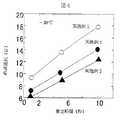
図2は、LiPF6を1モル濃度(mol/l)(以後、このモル濃度をMと記す)溶解した実施例1と比較例1の電解液の温度依存性を比較した結果を示す線図である。実施例1の電解液は−40℃の低温まで比較例1の電解液に比べて高い導電率を維持した。この様に、EMCとMAを併せて用いることは電解液の導電性向上に有効である。FIG. 2 is a diagram showing the results of comparing the temperature dependence of the electrolytic solutions of Example 1 and Comparative Example 1 in which LiPF6 was dissolved at 1molar concentration (mol / l) (hereinafter, this molar concentration is referred to as M) . It is. The electrolytic solution of Example 1 maintained high conductivity as compared with the electrolytic solution of Comparative Example 1 up to a low temperature of −40 ° C. Thus, using EMC and MA together is effective in improving the conductivity of the electrolytic solution.
次に、正極材料にLiMn1/3Ni1/3Co1/302を用い、導電材としてカーボンブラック(CB1)と黒鉛材(GF1)を用い、バインダとしてポリフッ化ビニリデン(PVDF)を用いて、乾燥時の固形分重量を下記の比、
LiMn1/3Ni1/3Co1/302:CB1:GF1:PVDF=86:9:2:3
となるように溶剤としてNMP(N一メチルピロリドン)を用い正極材ぺ一ストを調製した。この正極材ぺ一ストを正極集電体1として用いたアルミ箔に塗布し、80℃で乾燥、加圧ローラーでプレス、120℃で乾燥して正極電極層2を正極集電体1上に形成した。Next, LiMn1/3 Ni1/3 Co1/3 02 is used as the positive electrode material, carbon black (CB1) and graphite material (GF1) are used as the conductive material, and polyvinylidene fluoride (PVDF) is used as the binder. The solid content weight at the time of drying is as follows:
LiMn1/3 Ni1/3 Co1/3 02 : CB1: GF1: PVDF = 86: 9: 2: 3
A positive electrode material paste was prepared using NMP (N-methylpyrrolidone) as a solvent. This positive electrode material paste is applied to the aluminum foil used as the positive electrode
負極材料にクレハ化学製のカーボトロンPを用い、導電材としてカーボンブラック(CB2)を用い、バインダとしてPVDFを用いて、乾燥時の固形分重量を下記の比、
カーボトロンP:CB1:PVDF=88:5:7
となるように溶剤としてNMPを用い負極材ぺ一ストを調製した。この負極材ぺ一ストを負極集電体3として用いた銅箔に塗布し、80℃で乾燥、加圧ローラーでプレス、120℃で乾燥して負極電極層4を負極集電体3上に形成した。Carbotron P made by Kureha Chemical is used as the negative electrode material, carbon black (CB2) is used as the conductive material, PVDF is used as the binder, and the solid content weight at the time of drying is as follows:
Carbotron P: CB1: PVDF = 88: 5: 7
A negative electrode material paste was prepared using NMP as a solvent. The negative electrode material paste is applied to the copper foil used as the negative electrode
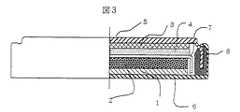
図3は、本実施例で作成したコイン型電池の片側断面である。以上で作製した正極と負極の電極を直径15mmの円形に打ち抜き加工し、厚み25μmのポリエチレン製セパレータ7を挟んで、電解液に実施例1の電解液1を注液して、正極をケース6に入れ、負極をのせてケース5で蓋をし、ガスケット8を挟んでカシメ、図3に示す構造のコイン型電池(実施例1)を作製した。 FIG. 3 is a cross-sectional side view of the coin-type battery prepared in this example. The positive electrode and the negative electrode manufactured as described above are punched into a circle having a diameter of 15 mm, the polyethylene separator 7 having a thickness of 25 μm is sandwiched therebetween, and the
電解液として、溶媒を以下の容積組成比
EC:DMC:EMC:MA=3:3:3:1
で混合したものを用い、リチウム塩としてLIPF6を1Mになるように溶解し、VCを0.8重量%混合した電解液を作製した。As an electrolytic solution, a solvent is used in the following volume composition ratio EC: DMC: EMC: MA = 3: 3: 3: 1
The electrolyte solution was prepared by dissolving LIPF6 as a lithium salt to 1 M and mixing 0.8 wt% of VC.
電解液として、溶媒を以下の容積組成比
EC:DMC:EMC:MA=3:3:3:1
で混合したものを用い、リチウム塩としてLiPF6を1Mになるように溶解し、VCを0.8重量%、(式5)の化合物(テトラキス[トリフロロアセトキシ]ホウ酸リチウム;TTFBL)を0.01M混合し電解液を作製した。As an electrolytic solution, a solvent is used in the following volume composition ratio EC: DMC: EMC: MA = 3: 3: 3: 1
LiPF6 as a lithium salt is dissolved so as to be 1 M, VC is 0.8% by weight, and the compound of formula 5 (tetrakis [trifluoroacetoxy] lithium borate; TTFBL) is 0 An electrolytic solution was prepared by mixing 0.01M.
これらの比較例1、実施例2、実施例3の電解液を用いて、電解液を注液したコイン型電池を実施例1と同様にして作製した。
(セル抵抗の評価)
図4は、以上作製した電池の−30℃での直流抵抗(DCR)を評価、比較したその結果を示す線図である。作製した電池を2mAの定電流で充電し、更に、4.1V定電圧で電流が20μAを切るまで充電し、その後、30分の運転休止を挟んで、定電流2mAで2.7Vまで放電した。この操作を3回繰り返した後、更に、定電流2mAで3.8Vまで充電した。この状態で、電流値20mA、40mA、60mAの電流値で終止電圧2.5Vまで放電し、I−V特性を計測し、その傾きから放電時(出力時)の電池抵抗を評価した。実施例2はVCを混合することで、電極表面での抵抗が増加していることが分かった。しかし、TTFBLを添加することで、実施例3の電池ではVCによる低温での抵抗上昇を抑制できることが分かった。これは、嵩高なTTFBLアニオンが電極被膜の密度を低減しているためと思われる。これにより、低温でのリチウムイオンの移動が良好になり、電池抵抗が低くなったものと考えられる。Using the electrolytic solutions of Comparative Example 1, Example 2, and Example 3, coin-type batteries into which the electrolytic solution was injected were produced in the same manner as in Example 1.
(Evaluation of cell resistance)
FIG. 4 is a diagram showing the results of evaluating and comparing the direct current resistance (DCR) at −30 ° C. of the battery produced as described above. The produced battery was charged at a constant current of 2 mA, further charged at a constant voltage of 4.1 V until the current fell below 20 μA, and then discharged to 2.7 V at a constant current of 2 mA with a 30-minute shutdown. . After repeating this operation three times, the battery was further charged to 3.8 V at a constant current of 2 mA. In this state, discharge was performed at current values of 20 mA, 40 mA, and 60 mA to a final voltage of 2.5 V, the IV characteristics were measured, and the battery resistance at the time of discharge (output) was evaluated from the slope. In Example 2, it was found that the resistance on the electrode surface was increased by mixing VC. However, it was found that by adding TTFBL, the battery of Example 3 can suppress an increase in resistance at a low temperature due to VC. This seems to be because the bulky TTFBL anion reduces the density of the electrode coating. Thereby, the movement of lithium ions at a low temperature is improved, and the battery resistance is considered to be low.
図5は、本実施例の捲回型電池の片側断面図である。図5に示す捲回型電池を作製し、−30℃の電池抵抗とパルスサイクル特性を評価、比較した。電池を定電流0.7Aで4.1Vまで充電し、4.1V定電圧で電流値が20mAになるまで充電し、30分の運転休止の後、0.7Aで2.7Vまで放電した。この操作を3回繰り返した。次に、電池を3.8Vまで定電流O.7Aで充電し、10Aで10s放電し、再度3.8Vまで定電流で充電し、20Aで10s放電し、再度3.8Vまで充電し、30Aで10s放電した。この際のI−V特性から、電池のDCRを評価した。また、50℃に設定した恒温槽中で、20A−2sの充放電を繰り返すパルスサイクル試験を行い、1000h後の25℃の容量及び25℃と−30℃のDCRを評価した。 FIG. 5 is a half sectional view of the wound battery of the present example. The wound battery shown in FIG. 5 was produced, and the battery resistance at −30 ° C. and the pulse cycle characteristics were evaluated and compared. The battery was charged at a constant current of 0.7 A to 4.1 V, charged at a constant voltage of 4.1 V until the current value reached 20 mA, and after 30 minutes of operation stop, discharged at 0.7 A to 2.7 V. This operation was repeated three times. Next, the battery was charged with a constant current O.D. The battery was charged at 7 A, discharged at 10 A for 10 s, charged again at a constant current up to 3.8 V, discharged at 20 A for 10 s, charged again at 3.8 V, and discharged at 30 A for 10 s. The DCR of the battery was evaluated from the IV characteristics at this time. Moreover, the pulse cycle test which repeats charging / discharging of 20A-2s in the thermostat set to 50 degreeC was done, and the capacity | capacitance of 25 degreeC after 1000 h and DCR of 25 degreeC and -30 degreeC were evaluated.
表1は、図5に示す捲回型電池における実施例1〜3及び比較例1の初期の特性及びパルスサイクル後の特性を示すものである。電解液にMAを混合した実施例1の電池は、炭酸エステルのみから構成される比較例1の電池に比べ初期のDCRが10−15%低減している。即ち、入出カの10−15%の向上が期待できる。また、パルスサイクル後のDCR上昇率も比較例1の電池に比べて1O−15%抑制された。 Table 1 shows the initial characteristics and the characteristics after the pulse cycle of Examples 1 to 3 and Comparative Example 1 in the wound battery shown in FIG. In the battery of Example 1 in which MA was mixed with the electrolytic solution, the initial DCR was reduced by 10-15% compared to the battery of Comparative Example 1 composed only of carbonate ester. That is, an improvement of 10-15% in input / output can be expected. In addition, the DCR increase rate after the pulse cycle was also suppressed by 1O-15% as compared with the battery of Comparative Example 1.
更に、実施例1の電池にVCを混合した電池では、実施例1の電池に比べ初期のDCRは若干上昇するものの、パルスサイクル後のDCR上昇が大幅に抑制された。これは、VCの提供する電極被膜がパルスサイクルでの電解液の副反応を抑制するためと考えられる。 Further, in the battery in which VC was mixed with the battery of Example 1, the initial DCR slightly increased as compared with the battery of Example 1, but the DCR increase after the pulse cycle was significantly suppressed. This is presumably because the electrode coating provided by VC suppresses the side reaction of the electrolyte in the pulse cycle.
更には、実施例2にTTFBLを添加した実施例3の電池では、初期のDCRを25℃、−30℃ともに大幅に低減することに成功した。更に、パルスサイクル後のDCRも実施例2比比べ上昇率では劣るものの絶対値では低い値を維持し、良好なサイクル特性になっていた。以上のように、MAは低温特性の改善に効果があり、VCはサイクル特性の向上に寄与し、TTFBLは低温特性の大幅な改善に効果があることが確認された。 Furthermore, in the battery of Example 3 in which TTFBL was added to Example 2, the initial DCR was successfully reduced significantly at both 25 ° C. and −30 ° C. Furthermore, although the DCR after the pulse cycle was inferior in the rate of increase compared to Example 2, the absolute value was kept low and the cycle characteristics were good. As described above, it was confirmed that MA is effective in improving low temperature characteristics, VC contributes to improving cycle characteristics, and TTFBL is effective in greatly improving low temperature characteristics.
電解液として、溶媒を以下の容積組成比
EC:DMC:EMC:EA=3:3:3:1
で混合したものを用い、リチウム塩としてLiPF6を1Mになるように溶解し、VCを0.8重量%混合した電解液を調製し、実施例1と同じ仕様の電池に注液して実施例4の電池を作製した。As an electrolytic solution, the following volume composition ratio is used: EC: DMC: EMC: EA = 3: 3: 3: 1
The electrolyte solution was prepared by dissolving LiPF6 as a lithium salt so as to be 1 M, and mixing 0.8 wt% of VC, and injecting it into a battery having the same specifications as in Example 1. The battery of Example 4 was produced.
電解液として、溶媒を以下の容積組成比
EC:DMC:EMC:EA=3:3:3:1
で混合したものを用い、リチウム塩としてLiPF6を1Mになるように溶解し、VCを0.8重量%及びTTFBLを0.01M混合し電解液を調製し、実施例1と同じ仕様の電池に注液して実施例5の電池を作製した。As an electrolytic solution, the following volume composition ratio is used: EC: DMC: EMC: EA = 3: 3: 3: 1
A battery having the same specifications as in Example 1 was prepared by dissolving LiPF6 as a lithium salt to 1 M, mixing 0.8 wt% of VC and 0.01 M of TTFBL. The battery of Example 5 was produced.
電解液として、溶媒を以下の容積組成比
EC:DMC:EMC:PM=3:3:3:1
で混合したものを用い、リチウム塩としてLiPF6を1Mになるように溶解し、VCを0.8重量%混合した電解液を調製し、実施例1と同じ仕様の電池に注液して実施例6の電池を作製した。As an electrolytic solution, the following volume composition ratio of EC: DMC: EMC: PM = 3: 3: 3: 1
In using a mixture, the LiPF6 as a lithium salt was dissolved so as to 1M, the electrolytic solution obtained by mixing 0.8by weight% of VC was prepared, injected into cells of the same specifications as in Example 1 A battery of Example 6 was produced.
電解液として、溶媒を以下の容積組成比
EC:DMC:EMC:PM=3:3:3:1
で混合したものを用い、リチウム塩としてLiPF6を1Mになるように溶解し、VCを0.8重量%及びTTFBLを0.01M混合した電解液を調製し、実施例1と同じ仕様の電池に注液して実施例7の電池を作製した。As an electrolytic solution, a solvent is used in the following volume composition ratio EC: DMC: EMC: PM = 3: 3: 3: 1
LiPF6 as a lithium salt was dissolved so as to be 1 M, VC was 0.8 wt%, and TTFBL was0 . An electrolyte solution mixed with 01M was prepared and poured into a battery having the same specifications as in Example 1, and a battery of Example 7 was produced.
電解液として、溶媒を以下の容積組成比
EC:DMC:EMC:PE=3:3:3:1
で混合したものを用い、リチウム塩としてLiPF6を1Mになるように溶解し、VCを0.8重量%混合した電解液を調製し、実施例1と同じ仕様の電池に注液して実施例8の電池を作製した。As an electrolytic solution, a solvent is used in the following volume composition ratio EC: DMC: EMC: PE = 3: 3: 3: 1
The electrolyte solution was prepared by dissolving LiPF6 as a lithium salt so as to be 1 M, and mixing 0.8 wt% of VC, and injecting it into a battery having the same specifications as in Example 1. The battery of Example 8 was produced.
電解液として、溶媒を以下の容積組成比
EC:DMC:EMC:PE=3:3:3:1
で混合したものを用い、リチウム塩としてLiPF6を1Mになるように溶解し、VCを0.8重量%及びTTFBLを0.01M混合した電解液を調製し、実施例1と同じ仕様の電池に注液して実施例9の電池を作製した。As an electrolytic solution, a solvent is used in the following volume composition ratio EC: DMC: EMC: PE = 3: 3: 3: 1
In using a mixture, the LiPF6 as a lithium salt was dissolved so as to 1M, the VC 0.8by weight% and
電解液として、溶媒を以下の容積組成比
EC:DMC:EMC:TFMA=3:3:3:1
で混合したものを用い、リチウム塩としてLiPF6を1Mになるように溶解し、VCを0.8重量%混合した電解液を調製し、実施例1と同じ仕様の電池に注液して実施例10の電池を作製した。As an electrolytic solution, a solvent is used in the following volume composition ratio EC: DMC: EMC: TFMA = 3: 3: 3: 1
The electrolyte solution was prepared by dissolving LiPF6 as a lithium salt so as to be 1 M, and mixing 0.8 wt% of VC, and injecting it into a battery having the same specifications as in Example 1. The battery of Example 10 was produced.
電解液として、溶媒を以下の容積組成比
EC:DMC=EMC:TFMA=3:3:3:1
で混合したものを用い、リチウム塩としてLiPF6を1Mになるように溶解し、VCを0.8重量%及びTTFBLを0.01M混合した電解液を調製し、実施例1と同じ仕様の電池に注液して実施例11の電池を作製した。
(実施例4〜11の電池特性の評価)
表2は、実施例4〜11について実施例1〜3の電池と同様の試験・評価を行った結果を示すものである。MAをEAに替えた実施例4の電池は実施例2に比べDCRが25℃で3mΩ低くなり、−30℃では20mΩ低くなった。更に、実施例4の電解液にTTFBLを添加した実施例5の電池は実施例4の電池に比べDCRが25℃で3mΩ低くなり、−30℃では30mΩ低くなった。As an electrolytic solution, the following volume composition ratio of EC: DMC = EMC: TFMA = 3: 3: 3: 1
LiPF6 as a lithium salt was dissolved so as to be 1 M, VC was 0.8 wt%, and TTFBL was0 . An electrolyte solution mixed with 01M was prepared, and poured into a battery having the same specifications as in Example 1, to produce a battery of Example 11.
(Evaluation of battery characteristics of Examples 4 to 11)
Table 2 shows the results of tests and evaluations similar to the batteries of Examples 1 to 3 for Examples 4 to 11. The battery of Example 4 in which MA was replaced with EA had a DCR of 3 mΩ lower at 25 ° C. and 20 mΩ lower at −30 ° C. compared to Example 2. Further, the battery of Example 5 in which TTFBL was added to the electrolyte solution of Example 4 had a DCR of 3 mΩ lower at 25 ° C. and 30 mΩ lower at −30 ° C. than that of Example 4.
MAをPMに替えた実施例6の電池のDCRは比較例1の電池に比べDCRが25℃で2mΩ低くなり、−30℃では45mΩ低くなった。実施例6の電解液にTTFBLを添加した実施例7の電池は比較例1の電池に比べDCRが25℃で7mΩ低くなり、−30oCでは55mΩ低くなった。 The DCR of the battery of Example 6 in which MA was replaced with PM was 2 mΩ lower at 25 ° C. and 45 mΩ at −30 ° C. than that of Comparative Example 1. The battery of Example 7 in which TTFBL was added to the electrolyte solution of Example 6 had a DCR of 7 mΩ lower at 25 ° C. and 55 mΩ at −30 ° C. than that of Comparative Example 1.
MAをPEに替えた実施例8の電池のDCRは比較例1の電池に比べDCRが25℃で3mΩ低くなり、−30℃では40mΩ低くなった。更に、実施例8の電解液にTTFBLを添加した実施例9の電池は比較例1の電池に比べDCRが25℃で7mΩ低くなり、−30℃では95mΩ低くなった。 The DCR of the battery of Example 8 in which MA was replaced with PE was 3 mΩ lower at 25 ° C. than the battery of Comparative Example 1, and 40 mΩ lower at −30 ° C. Further, the battery of Example 9 in which TTFBL was added to the electrolyte solution of Example 8 had a DCR of 7 mΩ lower at 25 ° C. and 95 mΩ lower at −30 ° C. than the battery of Comparative Example 1.
MAをTFMAに替えた実施例10の電池のDCRは比較例1の電池に比べDCRが25℃で2mΩ低くなり、−30℃では30mΩ低くなった。更に、実施例10の電解液にTTFBLを添加した実施例11の電池は比較例1の電池に比べDCRが25℃で8mΩ低くなり、−30℃では95mΩ低くなった。パルスサイクル試験後においても、これら実施例電池は比較例電池に比べ、25℃、−30℃ともに低いDCRを維持していた。 The DCR of the battery of Example 10 in which MA was replaced with TFMA was 2 mΩ lower at 25 ° C. and 30 mΩ at −30 ° C. than the battery of Comparative Example 1. Further, the battery of Example 11 in which TTFBL was added to the electrolytic solution of Example 10 had a DCR of 8 mΩ lower at 25 ° C. and 95 mΩ lower at −30 ° C. than that of Comparative Example 1. Even after the pulse cycle test, these example batteries maintained a low DCR at both 25 ° C. and −30 ° C. compared to the comparative example batteries.
電解液として、溶媒を以下の容積組成比
EC:DMC:EMC:MA=3:3:3:1
で混合したものを用い、リチウム塩としてLiPF6を1Mになるように溶解し、MVCを0.8重量%混合した電解液を調製し、実施例1と同じ仕様の電池に注液して実施例12の電池を作製した。As an electrolytic solution, a solvent is used in the following volume composition ratio EC: DMC: EMC: MA = 3: 3: 3: 1
In using a mixture, the LiPF6 as a lithium salt was dissolved so as to 1M, the
電解液として、溶媒を以下の容積組成比
EC:DMC:EMC:MA=3:3:3:1
で混合したものを用い、リチウム塩としてLiPF6を1Mになるように溶解し、MVCを0.8重量%混合し、さらに、TTFBLをO.01M混合した電解液を調製し、実施例1と同じ仕様の電池に注液して実施例13の電池を作製した。As an electrolytic solution, a solvent is used in the following volume composition ratio EC: DMC: EMC: MA = 3: 3: 3: 1
LiPF6 as a lithium salt is dissolved to 1 M, 0.8 wt% of MVC is mixed, and TTFBL is mixed with O.D. An electrolyte solution mixed with 01M was prepared, and poured into a battery having the same specifications as in Example 1, to produce a battery of Example 13.
電解液として、溶媒を以下の容積組成比
EC:DMC:EMC:MA:TFPC=3:2:3:1:1
で混合したものを用い、リチウム塩としてLiPF6を1Mになるように溶解し、VCを0.8重量%混合した電解液を調製し、実施例1と同じ仕様の電池に注液して実施例14の電池を作製した。As an electrolytic solution, the following volume composition ratio was used: EC: DMC: EMC: MA: TFPC = 3: 2: 3: 1: 1
The electrolyte solution was prepared by dissolving LiPF6 as a lithium salt so as to be 1 M, and mixing 0.8 wt% of VC, and injecting it into a battery having the same specifications as in Example 1. The battery of Example 14 was produced.
電解液として、溶媒を以下の容積組成比
EC:DMC:EMC:MA:TFPC=3:2:3:1:1
で混合したものを用い、リチウム塩としてLiPF6を1Mになるように溶解し、VCを0.8重量%及びTTFBLを0.01M混合した電解液を調製し、実施例1と同じ仕様の電池に注液して実施例15の電池を作製した。As an electrolytic solution, the following volume composition ratio of EC: DMC: EMC: MA: TFPC = 3: 2: 3: 1: 1
A battery having the same specifications as in Example 1 was prepared by dissolving LiPF6 as a lithium salt so as to be 1 M, and preparing an electrolyte solution containing 0.8 wt% VC and 0.01 M TTFBL. The battery of Example 15 was produced.
電解液として、溶媒を以下の容積組成比
EC:DMC:EMC:MA:VEC=3:2.5:3:1:0.5
で混合したものを用い、リチウム塩としてLiPF6を1Mになるように溶解し、VCを0、8重量%混合した電解液を調製し、実施例1と同じ仕様の電池に注液して実施例16の電池を作製した。As an electrolytic solution, the following volume composition ratio of EC: DMC: EMC: MA: VEC = 3: 2.5: 3: 1: 0.5
In this case, LiPF6 as a lithium salt is dissolved to 1 M, and an electrolyte solution is prepared by mixing 0,8% by weight of VC. The solution is injected into a battery having the same specifications as in Example 1. The battery of Example 16 was made.
電解液として、溶媒を以下の容積組成比
EC:DMC:EMC:MA:VEC=3:2.5:3:1:0.5
で混合したものを用い、リチウム塩としてLiPF6を1Mになるように溶解し、VCを0.8重量%混合し、さらに、TTFBLを0.01M混合した電解液を調製し、実施例1と同じ仕様の電池に注液して実施例17の電池を作製した。
As an electrolytic solution, the following volume composition ratio of EC: DMC: EMC: MA: VEC = 3: 2.5: 3: 1: 0.5
LiPF6 as a lithium salt was dissolved so as to be 1 M, VC was mixed by 0.8 wt%, and TTFBL was adjusted to0 . An electrolyte solution mixed with 01M was prepared, and poured into a battery having the same specifications as in Example 1, to produce a battery of Example 17.
電解液として、溶媒を以下の容積組成比
EC:DMC:EMC:MA:ClEC=3:2.5:3:1:0.5
で混合したものを用い、リチウム塩としてLiPF6を1Mになるように溶解し、VCを0.8重量%混合した電解液を調製し、実施例1と同じ仕様の電池に注液して実施例18の電池を作製した。As an electrolytic solution, a solvent is used in the following volume composition ratio EC: DMC: EMC: MA: ClEC = 3: 2.5: 3: 1: 0.5
The electrolyte solution was prepared by dissolving LiPF6 as a lithium salt so as to be 1 M, and mixing 0.8 wt% of VC, and injecting it into a battery having the same specifications as in Example 1. The battery of Example 18 was produced.
電解液として、溶媒を以下の容積組成比
EC:DMC=EMC:MA:ClEC=3:2.5:3:1:0.5
で混合したものを用い、リチウム塩としてLiPF6を1Mになるように溶解し、VCを0.8重量%及びTTFBLを0.01M混合した電解液を調製し、実施例1と同じ仕様の電池に注液して実施例19の電池を作製した。
(実施例12〜19の電池特性の評価)
表3は、実施例12〜19について実施例1〜3の電池と同様の試験・評価を行った結果を示すものである。実施例2の電解液のVCをMVCに変更した実施例12の電池は、比較例1の電池に比べDCRが25℃で3mΩ、−30℃で0mΩ小さくなった。更に、実施例12の電解液にTTFBLを混合した実施例13の電池では、DCRが比較例1の電池に比べ25℃で6mΩ、−30℃で105mΩ小さくなった。As an electrolytic solution, the following volume composition ratio of EC: DMC = EMC: MA: ClEC = 3: 2.5: 3: 1: 0.5
LiPF6 as a lithium salt was dissolved so as to be 1 M, and an electrolyte solution was prepared by mixing 0.8 wt% of VC and 0.01 M of TTFBL. The battery of Example 19 was produced by pouring the liquid.
(Evaluation of battery characteristics of Examples 12 to 19)
Table 3 shows the results of tests and evaluations similar to the batteries of Examples 1 to 19 for Examples 12 to 19. The battery of Example 12 in which the electrolytic solution VC of Example 2 was changed to MVC had a DCR of 3 mΩ at 25 ° C. and 0 mΩ at −30 ° C. compared to the battery of Comparative Example 1. Furthermore, in the battery of Example 13 in which TTFBL was mixed with the electrolyte solution of Example 12, the DCR was 6 mΩ smaller at 25 ° C. and 105 mΩ at −30 ° C. than the battery of Comparative Example 1.
実施例2の電解液にTFPCを混合した実施例14の電池では、DCRが比較例1の電池に比べ25℃で1mΩ、−30℃で70mΩ小さくなった。更に、実施例14の電解液にTTFBLを混合した実施例15の電池では、DCRが比較例1の電池に比べ25℃で3mΩ、−30℃で95mΩ小さくなった。 In the battery of Example 14 in which TFPC was mixed with the electrolyte solution of Example 2, the DCR was 1 mΩ lower at 25 ° C. and 70 mΩ at −30 ° C. than the battery of Comparative Example 1. Further, in the battery of Example 15 in which TTFBL was mixed with the electrolytic solution of Example 14, the DCR was 3 mΩ at 25 ° C. and 95 mΩ at −30 ° C. smaller than that of Comparative Example 1.
実施例2の電解液にVECを混合した実施例16の電池では、DCRが比較例1の電池に比べ25℃で3mΩ、−30℃で50mΩ小さくなった。更に、実施例16の電解液にTTFBLを混合した実施例17の電池では、DCRが比較例1の電池に比べ25℃で8mΩ、−30℃で75mΩ小さくなった。 In the battery of Example 16 in which VEC was mixed with the electrolytic solution of Example 2, the DCR was 3 mΩ lower at 25 ° C. and 50 mΩ at −30 ° C. than the battery of Comparative Example 1. Furthermore, in the battery of Example 17 in which TTFBL was mixed with the electrolyte solution of Example 16, the DCR was 8 mΩ lower at 25 ° C. and 75 mΩ at −30 ° C. than the battery of Comparative Example 1.
実施例2の電解液にClECを混合した実施例18の電池では、DCRが比較例1の電池に比べ25℃で2mΩ、−30℃で45mΩ小さくなった。更に、実施例18の電解液にTTFBLを混合した実施例19の電池では、DCRが比較例1の電池に比べ25℃で7mΩ、−30℃で45mΩ小さくなった。パルスサイクル試験後においても、これら実施例電池は比較例電池に比べ、25℃、−30℃ともに低いDCRを維持していた。 In the battery of Example 18 in which ClEC was mixed with the electrolyte solution of Example 2, the DCR was 2 mΩ lower at 25 ° C. and 45 mΩ at −30 ° C. than the battery of Comparative Example 1. Furthermore, in the battery of Example 19 in which TTFBL was mixed with the electrolyte solution of Example 18, the DCR was 7 mΩ smaller at 25 ° C. and 45 mΩ at −30 ° C. than the battery of Comparative Example 1. Even after the pulse cycle test, these example batteries maintained a low DCR at both 25 ° C. and −30 ° C. compared to the comparative example batteries.
又、本実施例においては、高出カ型リチウムニ次電池として、これまでリチウムニ次電池にくらべ低温でのDCRが改善されており、従来電池に比べ低温での入出力性能が改善され、ハイブリツド自動車の電源や自動車の電動制御系の電源やバツクアツプ電源として広く利用可能であり、電動エ具、フオークリフトなどの産業用機器の電源としても好適である。 Further, in this embodiment, as a high output type lithium secondary battery, DCR at a low temperature is improved as compared with the lithium secondary battery so far, and the input / output performance at a low temperature is improved as compared with the conventional battery, and the hybrid vehicle. It can be widely used as a power source for automobiles, an electric control system for automobiles and a backup power source, and is also suitable as a power source for industrial equipment such as electric tools and forklifts.
更に、本実施例のリチウムニ次電池は、特に低温での出カ特性が向上しており、寒冷地における使用も多い自動車への利用に有効である。そして、電池を組み電池にして実際に数百ボルトのモジュールとして用いる場合においては、低温特性が高いため必要な組電池の本数を低減することができるので、モジュールを小型、軽量化できる効果がある。 Further, the lithium secondary battery of this example has improved output characteristics particularly at low temperatures, and is effective for use in automobiles that are frequently used in cold regions. When the battery is used as an assembled battery and actually used as a module of several hundred volts, since the low temperature characteristics are high, the number of necessary assembled batteries can be reduced, so that the module can be reduced in size and weight. .
1…正極集電体アルミ箔、2…正極電極層、3…負極銅箔、4…負極電極層、5…負極ケース(蓋)、6…正極ケース、7…セパレータ、8…ガスケット、9…負極リード、10…正極リード、11…正極インシュレータ、12…負極インシュレータ、13…負極電池缶、14…ガスケット、15…正極電池蓋。
DESCRIPTION OF
Claims (6)
Translated fromJapanese(式1)で表される環状カーボネート溶媒
(式中、R1、R2、R3、R4は水素、フッ素、塩素、炭素数1〜3のアルキル基、フッ素化されたアルキル基のいずれかを表わし、R1、R2、R3、R4はそれぞれ同一でも異なっていても良い)
(式2)で表される鎖状カーボネート溶媒及び
(式中、R5、R6は水素、フッ素、塩素、炭素数1〜3のアルキル基、フッ素化されたアルキル基のいずれかを表わし、R5、R6はそれぞれ同一でも異なっていても良い)
(式3)で表される鎖状エステル溶媒
(式中、R7、R8は水素、フッ素、塩素、炭素数1〜3のアルキル基、フッ素化されたアルキル基のいずれかを表わし、R7、R8はそれぞれ同一でも異なっていても良い)
を含み、
容積比で、前記(式3)の1に対して、前記(式1)が3〜4及び前記(式2)が5〜6である
ことを特徴とするリチウムニ次電池。In a lithium secondary battery having a positive electrode capable of inserting and extracting lithium ions, a negative electrode capable of inserting and extracting lithium ions, a separator disposed between the positive electrode and the negative electrode, and an organic electrolyte in a container The organic electrolyte solution is
Cyclic carbonate solvent represented by (Formula 1)
(Wherein, R 1, R 2, R 3, R 4 represents hydrogen, offTsu-containing, chlorine, alkyl group having 1 to 3 carbon atoms, one of the fluorinated alkylgroup, R 1,R 2 , R3 and R4 may be the same or different)
A chain carbonate solvent represented by (Formula 2) and
(In the formula, R5 and R6 represent hydrogen, fluorine, chlorine, an alkyl group having 1 to 3 carbon atoms, or a fluorinated alkyl group, and R5 and R6 may be the same or different. good)
A chain ester solvent represented by Formula 3
(Wherein, R 7,R 8 represents hydrogen, offTsu-containing, chlorine, alkyl group having 1 to 3 carbon atoms, one of the fluorinated alkylgroup, R 7,R 8 are different from each other in the same May be)
Including
The lithium secondary battery according to claim 1, wherein, in terms of volume ratio, 1 in the (Expression 3) is 3 to 4 in the (Expression 1) and 5 to 6 in the (Expression 2).
(式4)で表される化合物及び
(式中、R9、R10は水素、フッ素、塩素、炭素数1〜3のアルキル基、フッ素化されたアルキル基のいずれかを表わし、R9、R10はそれぞれ同一でも異なっていても良い)
(式5)で表される化合物
の少なくとも1種を含み、
リチウム塩としてLiPF6が1モル濃度溶解された前記有機電解液中に前記(式4)で表される化合物が0.8重量%及び前記(式5)で表される化合物が0.01モル濃度有することを特徴とするリチウムニ次電池。The organic electrolyte solution according to claim 1,
A compound represented by (formula 4) and
(In the formula, R9 and R10 each represent hydrogen, fluorine, chlorine, an alkyl group having 1 to 3 carbon atoms, or a fluorinated alkyl group, and R9 and R10 may be the same or different. good)
Compound represented by Formula 5
Including at least one of
Wherein said organic electrolytic solution LiPF6 was 1 molconcentration dissolved as a lithium salt compound compound represented by formula (4) is expressed by 0.8 wt% and the (Formula 5) is 0.01 moles A lithium secondary battery having aconcentration .
Priority Applications (2)
| Application Number | Priority Date | Filing Date | Title |
|---|---|---|---|
| JP2004357502AJP4997699B2 (en) | 2004-12-10 | 2004-12-10 | Lithium secondary battery |
| US11/296,277US20060154149A1 (en) | 2004-12-10 | 2005-12-08 | Lithium secondary battery |
Applications Claiming Priority (1)
| Application Number | Priority Date | Filing Date | Title |
|---|---|---|---|
| JP2004357502AJP4997699B2 (en) | 2004-12-10 | 2004-12-10 | Lithium secondary battery |
Publications (2)
| Publication Number | Publication Date |
|---|---|
| JP2006164860A JP2006164860A (en) | 2006-06-22 |
| JP4997699B2true JP4997699B2 (en) | 2012-08-08 |
Family
ID=36653635
Family Applications (1)
| Application Number | Title | Priority Date | Filing Date |
|---|---|---|---|
| JP2004357502AExpired - LifetimeJP4997699B2 (en) | 2004-12-10 | 2004-12-10 | Lithium secondary battery |
Country Status (2)
| Country | Link |
|---|---|
| US (1) | US20060154149A1 (en) |
| JP (1) | JP4997699B2 (en) |
Families Citing this family (18)
| Publication number | Priority date | Publication date | Assignee | Title |
|---|---|---|---|---|
| JP4349321B2 (en) | 2004-12-10 | 2009-10-21 | ソニー株式会社 | battery |
| CN101218706B (en)* | 2005-06-10 | 2011-09-28 | 三菱化学株式会社 | Nonaqueous electrolyte, nonaqueous electrolyte secondary battery and carbonate compound |
| KR100816208B1 (en)* | 2007-03-27 | 2008-03-28 | 삼성에스디아이 주식회사 | Electrolyte for lithium ion secondary battery and lithium ion secondary battery comprising same |
| JP5338041B2 (en)* | 2007-06-05 | 2013-11-13 | ソニー株式会社 | Negative electrode for secondary battery and secondary battery |
| JP5338151B2 (en)* | 2008-06-16 | 2013-11-13 | 三菱化学株式会社 | Non-aqueous electrolyte and non-aqueous electrolyte battery |
| FR2948232B1 (en)* | 2009-07-16 | 2011-08-26 | Commissariat Energie Atomique | LIQUID ELECTROLYTE FOR LITHIUM ACCUMULATOR COMPRISING A MIXTURE OF NONAQUEOUS ORGANIC SOLVENTS |
| US9673450B2 (en) | 2011-09-02 | 2017-06-06 | Solvay Sa | Lithium ion battery |
| JP6178316B2 (en) | 2011-09-02 | 2017-08-09 | イー・アイ・デュポン・ドウ・ヌムール・アンド・カンパニーE.I.Du Pont De Nemours And Company | Fluorinated electrolyte composition |
| JP6319305B2 (en) | 2012-06-01 | 2018-05-09 | ソルベー エスアー | Lithium ion battery |
| US10044066B2 (en) | 2012-06-01 | 2018-08-07 | Solvary SA | Fluorinated electrolyte compositions |
| US10916805B2 (en) | 2013-04-04 | 2021-02-09 | Solvay Sa | Nonaqueous electrolyte compositions |
| KR102304201B1 (en)* | 2013-07-19 | 2021-09-23 | 바스프 에스이 | Use of reactive lithium alkoxyborates as electrolyte additives in electrolytes for lithium ion batteries |
| US20170294677A1 (en)* | 2014-08-27 | 2017-10-12 | Hsc Corporation | Fluorine-Substituted Propylene Carbonate-Based Electrolytic Solution and Lithium-Ion Battery |
| HUE054899T2 (en) | 2014-11-21 | 2021-10-28 | Daikin Ind Ltd | Electrolyte solution containing unsaturated cyclic carbonates, electrochemical device and lithium-ion secondary battery comprising the same |
| JP6693393B2 (en)* | 2016-11-16 | 2020-05-13 | トヨタ自動車株式会社 | Battery manufacturing method |
| JP7032115B2 (en)* | 2017-01-13 | 2022-03-08 | トヨタ自動車株式会社 | Non-aqueous electrolyte secondary battery |
| JP2021176131A (en)* | 2020-05-01 | 2021-11-04 | ダイキン工業株式会社 | Learning model generation method, program, storage medium and learned model |
| KR102633532B1 (en)* | 2021-08-26 | 2024-02-06 | 주식회사 엘지에너지솔루션 | Non-aqueous electrolyte and lithium secondary battery comprising the same |
Family Cites Families (11)
| Publication number | Priority date | Publication date | Assignee | Title |
|---|---|---|---|---|
| JP3199426B2 (en)* | 1991-12-27 | 2001-08-20 | 松下電器産業株式会社 | Non-aqueous electrolyte secondary battery |
| FR2719161B1 (en)* | 1994-04-22 | 1996-08-02 | Accumulateurs Fixes | Electrochemical rechargeable lithium battery with carbon anode. |
| JP3460407B2 (en)* | 1995-09-27 | 2003-10-27 | ソニー株式会社 | Non-aqueous electrolyte secondary battery |
| JPH09147910A (en)* | 1995-11-22 | 1997-06-06 | Sanyo Electric Co Ltd | Lithium secondary battery |
| US6040090A (en)* | 1997-04-15 | 2000-03-21 | Sanyo Electric Co., Ltd. | Positive electrode material for use in non-aqueous electrolyte battery, process for preparing the same, and non-aqueous electrolyte battery |
| EP1197494A3 (en)* | 2000-09-21 | 2004-05-26 | Kanto Kagaku Kabushiki Kaisha | New organic borate compounds and the nonaqueous electrolytes and lithium secondary batteries using the compounds |
| JP4639573B2 (en)* | 2002-03-25 | 2011-02-23 | 住友化学株式会社 | Method for producing positive electrode active material for non-aqueous secondary battery |
| JP2004296237A (en)* | 2003-03-26 | 2004-10-21 | Toshiba Corp | Non-aqueous electrolyte secondary battery |
| JP4417649B2 (en)* | 2003-04-11 | 2010-02-17 | パナソニック株式会社 | Nonaqueous electrolyte secondary battery |
| JP4062169B2 (en)* | 2003-05-20 | 2008-03-19 | 株式会社日立製作所 | Positive electrode material for lithium secondary battery |
| JP4283593B2 (en)* | 2003-05-22 | 2009-06-24 | 三菱化学株式会社 | Non-aqueous electrolyte and non-aqueous electrolyte secondary battery using the same |
- 2004
- 2004-12-10JPJP2004357502Apatent/JP4997699B2/ennot_activeExpired - Lifetime
- 2005
- 2005-12-08USUS11/296,277patent/US20060154149A1/ennot_activeAbandoned
Also Published As
| Publication number | Publication date |
|---|---|
| US20060154149A1 (en) | 2006-07-13 |
| JP2006164860A (en) | 2006-06-22 |
Similar Documents
| Publication | Publication Date | Title |
|---|---|---|
| JP5779639B2 (en) | Lithium secondary battery | |
| JP6631404B2 (en) | Non-aqueous electrolyte for non-aqueous electrolyte secondary battery, non-aqueous electrolyte secondary battery, and method of manufacturing non-aqueous electrolyte secondary battery | |
| US11799132B2 (en) | Non-aqueous electrolyte solution for lithium secondary battery and lithium secondary battery including the same | |
| JP4774426B2 (en) | Lithium secondary battery | |
| JP4997699B2 (en) | Lithium secondary battery | |
| CN113692668A (en) | Electrolyte solution for lithium secondary battery and lithium secondary battery comprising the same | |
| JP6005277B2 (en) | Lithium secondary battery with improved life characteristics | |
| KR102525619B1 (en) | Rechargeable lithium battery | |
| JP2007317582A (en) | Energy storing device | |
| JP2010232117A (en) | Lithium secondary battery | |
| US20230067792A1 (en) | Lithium Secondary Battery | |
| JP6656623B2 (en) | Non-aqueous electrolyte for non-aqueous electrolyte secondary battery, non-aqueous electrolyte secondary battery, and method for producing non-aqueous electrolyte secondary battery | |
| CN116325270A (en) | Nonaqueous electrolyte for lithium secondary battery and lithium secondary battery comprising same | |
| KR102829174B1 (en) | Lithium secondary battery having improved cycle property | |
| JP5724116B2 (en) | Non-aqueous electrolyte for lithium secondary batteries with excellent high-temperature storage characteristics | |
| JP5171854B2 (en) | Lithium secondary battery | |
| JP5193921B2 (en) | Lithium secondary battery | |
| KR102473691B1 (en) | Electrolyte for lithium secondary battery | |
| JP7118479B2 (en) | Electrolyte for lithium secondary battery and lithium secondary battery containing the same | |
| CN120345092A (en) | Lithium secondary battery | |
| KR20240100283A (en) | Lithium secondary battery | |
| JP2012138317A (en) | Lithium ion battery |
Legal Events
| Date | Code | Title | Description |
|---|---|---|---|
| A621 | Written request for application examination | Free format text:JAPANESE INTERMEDIATE CODE: A621 Effective date:20070405 | |
| A977 | Report on retrieval | Free format text:JAPANESE INTERMEDIATE CODE: A971007 Effective date:20091228 | |
| A131 | Notification of reasons for refusal | Free format text:JAPANESE INTERMEDIATE CODE: A131 Effective date:20100709 | |
| A521 | Request for written amendment filed | Free format text:JAPANESE INTERMEDIATE CODE: A523 Effective date:20100902 | |
| A131 | Notification of reasons for refusal | Free format text:JAPANESE INTERMEDIATE CODE: A131 Effective date:20110802 | |
| A521 | Request for written amendment filed | Free format text:JAPANESE INTERMEDIATE CODE: A523 Effective date:20110826 | |
| TRDD | Decision of grant or rejection written | ||
| A01 | Written decision to grant a patent or to grant a registration (utility model) | Free format text:JAPANESE INTERMEDIATE CODE: A01 Effective date:20120417 | |
| A01 | Written decision to grant a patent or to grant a registration (utility model) | Free format text:JAPANESE INTERMEDIATE CODE: A01 | |
| A61 | First payment of annual fees (during grant procedure) | Free format text:JAPANESE INTERMEDIATE CODE: A61 Effective date:20120430 | |
| R150 | Certificate of patent or registration of utility model | Free format text:JAPANESE INTERMEDIATE CODE: R150 Ref document number:4997699 Country of ref document:JP Free format text:JAPANESE INTERMEDIATE CODE: R150 | |
| FPAY | Renewal fee payment (event date is renewal date of database) | Free format text:PAYMENT UNTIL: 20150525 Year of fee payment:3 | |
| R250 | Receipt of annual fees | Free format text:JAPANESE INTERMEDIATE CODE: R250 | |
| S111 | Request for change of ownership or part of ownership | Free format text:JAPANESE INTERMEDIATE CODE: R313113 | |
| R350 | Written notification of registration of transfer | Free format text:JAPANESE INTERMEDIATE CODE: R350 | |
| R250 | Receipt of annual fees | Free format text:JAPANESE INTERMEDIATE CODE: R250 | |
| S111 | Request for change of ownership or part of ownership | Free format text:JAPANESE INTERMEDIATE CODE: R313111 | |
| R350 | Written notification of registration of transfer | Free format text:JAPANESE INTERMEDIATE CODE: R350 | |
| R250 | Receipt of annual fees | Free format text:JAPANESE INTERMEDIATE CODE: R250 | |
| R250 | Receipt of annual fees | Free format text:JAPANESE INTERMEDIATE CODE: R250 | |
| R250 | Receipt of annual fees | Free format text:JAPANESE INTERMEDIATE CODE: R250 | |
| R250 | Receipt of annual fees | Free format text:JAPANESE INTERMEDIATE CODE: R250 | |
| R250 | Receipt of annual fees | Free format text:JAPANESE INTERMEDIATE CODE: R250 | |
| EXPY | Cancellation because of completion of term |