JP4997141B2 - Vacuum processing apparatus and substrate temperature control method - Google Patents
Vacuum processing apparatus and substrate temperature control methodDownload PDFInfo
- Publication number
- JP4997141B2 JP4997141B2JP2008040183AJP2008040183AJP4997141B2JP 4997141 B2JP4997141 B2JP 4997141B2JP 2008040183 AJP2008040183 AJP 2008040183AJP 2008040183 AJP2008040183 AJP 2008040183AJP 4997141 B2JP4997141 B2JP 4997141B2
- Authority
- JP
- Japan
- Prior art keywords
- substrate
- mounting table
- elastic member
- holding device
- holes
- Prior art date
- Legal status (The legal status is an assumption and is not a legal conclusion. Google has not performed a legal analysis and makes no representation as to the accuracy of the status listed.)
- Active
Links
Images


Landscapes
- Container, Conveyance, Adherence, Positioning, Of Wafer (AREA)
- Chemical Vapour Deposition (AREA)
- Drying Of Semiconductors (AREA)
Description
Translated fromJapanese本発明は、基板を保持する基板トレイと、基板ホルダ、その基板ホルダを有する真空処理装置、及び基板の温度制御方法に関する。 The present invention relates to a substrate tray for holding a substrate, a substrate holder, a vacuum processing apparatus having the substrate holder, and a substrate temperature control method.
従来より、ドライエッチングや成膜等の基板処理を行う際、基板の冷却、加熱等の温度制御が行われる。
一般に、温度制御は、基板を載置する載置台に、加熱手段や冷却手段等の温度制御手段を設け、該温度制御手段で載置台を加熱又は冷却し、熱伝導により、載置台上の基板を加熱又は冷却する。
しかしながら、複数の基板を同時に載置台に配置して処理を行う場合、基板毎に温度のばらつきが生じ、処理速度にばらつきが生じやすい。
In general, temperature control is performed by providing temperature control means such as a heating means and a cooling means on a mounting table on which a substrate is mounted, and heating or cooling the mounting table with the temperature control means, and by heat conduction, the substrate on the mounting table. Is heated or cooled.
However, when processing is performed with a plurality of substrates placed on the mounting table at the same time, temperature variations occur between the substrates, and the processing speed tends to vary.
本発明は上記課題を解決するためのものであり、その目的は、複数枚の基板を同時に温度制御可能な装置及び方法を提供することである。 The present invention has been made to solve the above problems, and an object of the present invention is to provide an apparatus and method capable of simultaneously controlling the temperature of a plurality of substrates.
上記課題を解決するために本発明は、真空槽と、前記真空槽内に配置される基板保持装置と、前記基板保持装置が配置される載置台と、前記基板保持装置上に乗せられる押圧板と、前記押圧板を昇降させるピンと、を有し、前記基板保持装置は、二以上の第一の貫通孔が形成された支持板と、前記支持板の片面に配置された1又は複数のリング状の弾性部材とを有し、各前記第一の貫通孔は前記弾性部材で取り囲まれ、前記支持板の前記弾性部材とは反対側の面の各前記第一の貫通孔周囲の部分は、保持対象の基板が密着可能な着座部にされ、各前記第一の貫通孔は前記弾性部材で取り囲まれ、前記弾性部材は、前記支持板の裏面と、前記載置台の表面と密着した状態で、前記載置台上に配置されるように構成され、前記載置台には、前記弾性部材のリング内側の空間に熱媒体ガスを供給する供給路が設けられ、前記押圧板は、前記載置台上の前記基板保持装置を覆うように、前記ピンに取り付けられ、各前記第一の貫通孔上にそれぞれ前記基板を配置して各前記基板の裏面を前記第一の貫通孔内にそれぞれ露出させ、前記押圧板によって前記基板保持装置を前記載置台に押し付けて前記弾性部材を前記載置台に密着させると、前記基板と前記載置台の間の空間が前記弾性部材によって密閉され、前記熱媒体ガスが密閉された前記空間に供給されるように構成された真空処理装置である。
本発明は真空処理装置であって、前記支持板に重ね合わされるカバーを有し、前記カバーには、各前記第一の貫通孔上に配置された前記基板の表面がそれぞれ露出される第二の貫通孔が設けられ、前記ピンによって前記押圧板を降下させると、前記押圧板によって、前記カバーを介して前記支持板が押圧されて前記弾性部材が前記載置台に密着され、前記第二の貫通孔に露出する前記基板表面は、前記押圧板に設けられた第三の貫通孔内に露出される真空処理装置である。
本発明は真空処理装置であって、各前記第一の貫通孔は、別々の前記弾性部材でそれぞれ周囲が取り囲まれた真空処理装置である。
本発明は真空処理装置であって、前記弾性部材には、一の前記弾性部材で複数の前記第一の貫通孔を取り囲むものが含まれる真空処理装置である。
本発明は真空処理装置であって、前記弾性部材は、前記支持板の裏面に密着して取り付けられた真空処理装置である。
本発明は真空処理装置であって、前記載置台を冷却又は加熱する温度制御手段を有する真空処理装置である。
本発明は上記記載の真空処理装置を用い、複数枚の前記基板の温度を真空処理しながら制御する基板の温度制御方法であって、各前記第一の貫通孔をそれぞれ覆うように、前記支持板の表面上に複数の前記基板をそれぞれ配置し、各前記第一の貫通孔に前記基板の裏面が露出された状態で、前記第二の貫通孔内に露出する各前記基板の表面を真空処理する際に、前記温度制御手段で前記載置台を加熱又は冷却しながら各前記基板の裏面の密閉された前記空間に前記熱媒体を供給し、前記基板温度を測定して前記熱媒体の温度を制御して、前記基板の温度を制御する基板の温度制御方法である。
In order to solve the above problems, the present invention provides avacuum chamber, a substrate holding device disposed in the vacuum chamber, a mounting table on which the substrate holding device is disposed, and a pressing plate placed on the substrate holding device. And a pin for raising and lowering the pressing plate, and the substrate holding device includes a support plate in which two or more first through holes are formed, and one or a plurality of rings arranged on one side of the support plateEach of the first through holes is surrounded by the elastic member, and a portion of the surface of the support plate on the side opposite to the elastic member is aroundthe first through hole. The holding target substrate is a seating portion that can be in close contact, and each of the first through holes is surrounded by the elastic member, and the elastic member is in close contact with the back surface of the support plate and the surface of the mountingtable. The mounting table is configured to be disposed on the mounting table. A supply path for supplying a heat medium gas is provided in a space inside the ring of the member, and the pressing plate is attached to the pin so as to cover the substrate holding device on the mounting table, and each of the first penetrations The substrates are respectively disposed on the holes, the back surfaces of the substrates are exposed in the first through holes, and the elastic member is pressed against the mounting table by pressing the substrate holding device against the mounting table with the pressing plate. Is a vacuum processing apparatus configured such that a space between the substrate and the mounting table is sealed by the elastic member, and the heat medium gas is supplied to the sealed space .
The present invention is a vacuum processing apparatus, comprising a cover superimposed on the support plate, wherein the cover exposes a surface of the substrate disposed on each of the first through holes. When the pressing plate is lowered by the pin, the supporting plate is pressed by the pressing plate through the cover, and the elastic member is brought into close contact with the mounting table. The substrate surface exposed in the through hole is a vacuum processing apparatus exposed in a third through hole provided in the pressing plate.
The present invention provides avacuum processing apparatus,each of said first through hole is avacuum processing apparatus peripherally surrounded respectively by separate the elastic member.
The present invention provides avacuum processing apparatus, the elastic member is avacuum processing apparatus include those surrounding one of said elastic member in a plurality of thefirst throughhole.
The present invention provides avacuum processing apparatus, the elastic member is avacuum processing apparatus which is mounted in close contact with the back surface of the support plate.
The present invention is a vacuum processing apparatushaving a temperature control means for cooling or heating the mounting table .
The present inventionuses a vacuum processing apparatus described above, a temperature control method of the substrate for controllingwhile vacuum processing a plurality of temperature ofthe substrate so as tocover these first through holes respectively, said support A plurality of the substrates are respectively arranged on the surface of the plate, and the surface ofeach substrate exposed in the second through hole is vacuumed in a state where the back surface of the substrate is exposed in each first through hole. When processing, the heating medium is supplied to the sealed space on the back surface of each substrate while heating or cooling the mounting table by the temperature control means, and the temperature of the heating medium is measured by measuring the substrate temperature. Is a substrate temperature control methodfor controlling the substratetemperature by controlling the temperature of the substrate.
本発明は上記のように構成されており、弾性部材は支持板に接触し、基板には接触しないようになっている。従って、基板が弾性部材の構成材料(ゴム等)で汚染されない。
また、基板トレイを載置台上で昇降させるとき、昇降ピンを支持板に接触させれば、基板は昇降ピンにも接触しないので、昇降ピンにより基板が汚染されたり、破損することもない。The present invention is configured as described above, and the elastic member contacts the support plate and does not contact the substrate. Therefore, the substrate is not contaminated with the constituent material (rubber or the like) of the elastic member.
Further, when the substrate tray is moved up and down on the mounting table, if the lifting pins are brought into contact with the support plate, the substrate does not come into contact with the lifting pins either, so that the substrate is not contaminated or damaged by the lifting pins.
弾性部材は載置台に取り付けてもよいし、基板トレイの支持板に取り付けてもよい。更に、弾性部材を載置台と支持板のいずれにも取り付けずに分離させておき、基板トレイを載置台に置くときに、基板トレイと載置台の間に配置してもよい。
しかしながら、弾性部材を、載置台と支持板のいずれかに予め取り付けておいた方が、基板トレイの交換作業が簡易である。また、弾性部材は消耗品であるため、定期的に交換が必要であり、弾性部材を支持板に取り付けた方が、載置台に取り付けた場合に比べて、弾性部材の交換作業が簡易である。The elastic member may be attached to the mounting table or may be attached to the support plate of the substrate tray. Further, the elastic member may be separated without being attached to either the mounting table or the support plate, and may be disposed between the substrate tray and the mounting table when the substrate tray is placed on the mounting table.
However, it is easier to replace the substrate tray if the elastic member is attached in advance to either the mounting table or the support plate. In addition, since the elastic member is a consumable item, it needs to be replaced periodically, and replacing the elastic member is simpler when the elastic member is attached to the support plate than when the elastic member is attached to the mounting table. .
複数の基板を温度制御(冷却又は加熱)しながらエッチングや成膜等の処理をすることができる。各基板は熱媒体ガスに接触し、熱伝導で温度制御されるか、温度応答性が高い。複数枚の基板を同時に同じ処理速度で処理することができる。基板は弾性部材にも昇降ピンにも接触しないから、汚染されない。 A plurality of substrates can be subjected to processing such as etching and film formation while controlling the temperature (cooling or heating). Each substrate is in contact with the heat medium gas and is temperature-controlled by heat conduction or has high temperature responsiveness. A plurality of substrates can be processed at the same processing speed at the same time. The substrate is not contaminated because it does not contact the elastic member or the lifting pins.
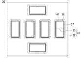
図5は本発明の基板保持装置30の平面図であり、基板保持装置30に基板を保持させる前の状態を示している。この基板保持装置30は、板状の基板トレイ31を有している。
基板トレイ31は支持板32と、支持板32を表面から裏面まで貫通する複数の貫通孔35とを有している。支持板32の片面(裏面)の各貫通孔35周囲にはリング状の溝(不図示)が設けられ、各貫通孔35は溝で取り囲まれている。FIG. 5 is a plan view of the
The
各溝にはリング状の弾性部材41が嵌め込まれ、各弾性部材41は底面が溝の底面と接触し、上部が溝から突き出された状態で、支持板32の裏面に貫通孔35を取り囲んで配置されている。
支持板32の弾性部材41が配置された側と反対側の面(表面)のうち、貫通孔35を取り囲む部分にはシール部材37が配置され、貫通孔35はシール部材37で取り囲まれている。A ring-shaped
Of the surface (surface) opposite to the side on which the
この基板保持装置30に保持される基板7の形状と大きさは予め分かっている。
貫通孔35の外周は基板7の平面形状外周よりも小さくされ、貫通孔35を覆うように基板7を支持板32表面に載せると、支持板32の貫通孔35周囲の部分と、シール部材37とが着座部36となり、基板7は裏面が貫通孔35内に露出し、縁部分が着座部36と接触した状態で、支持板32表面上に配置される。The shape and size of the
The outer periphery of the
ここでは、着座部36のうち、シール部材37が基板7と接触するようになっているが、シール部材37を設けず、支持板32の貫通孔周囲の部分で着座部36を構成し、基板7を支持板32に接触させてもよい。
図6は基板7を支持板32表面上に配置した状態を示しており、図6と、後述する図7、8では着座部36は省略している。Here, the sealing
FIG. 6 shows a state in which the
図9は板状のカバー33を示している。カバー33には貫通孔34が複数形成されている。
ここでは、カバー33の貫通孔34は基板7の平面形状より小さく、その間隔は、支持板32上の基板7の間隔と略等しくされ、各基板7上に、カバー33の貫通孔34が位置するように、カバー33を支持板32に重ね合わせると、基板7表面の処理されるべき処理領域は貫通孔34内に露出し、基板7表面の処理領域外の部分がカバー33と接触する。
基板7はカバー33と支持板32とで挟まれた状態になるから、ボルト等の締め付け部材で、カバー33を支持板32とを互いに押し付けると、基板7は押圧され、固定される。FIG. 9 shows a plate-
Here, the through-
Since the
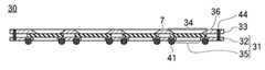
図3、7は締め付け部材44で固定した状態を示しており、図3は図7のA−A切断線断面図に相当する。この状態では、基板7は支持板32とカバー33に固定されているから、貫通孔34、35との位置関係が変化しない。従って、基板7表面の処理領域がカバー33の貫通孔34内に露出し、基板7の裏面が支持板32の貫通孔35内に露出した状態が維持される。 3 and 7 show a state of being fixed by the fastening
次に、上記基板保持装置30を用いた本発明の真空処理装置について説明する。
図1の符号1は本発明の真空処理装置1を示している。この真空処理装置1は、真空槽11と、基板ホルダ2とを有しており、基板ホルダ2は、載置台21と、上述した基板保持装置30を有している。Next, the vacuum processing apparatus of the present invention using the
載置台21は真空槽11の内部に配置されるか、真空槽11の一壁面(ここでは底面)に形成された貫通孔内に、表面を真空槽11の内部空間に向けて配置され、いずれの場合も、載置台21の少なくとも表面が真空槽11内部に位置する。 The mounting table 21 is disposed inside the
ここでは、載置台21は真空槽11壁面の貫通孔内に配置されている。当該貫通孔の内壁面と、載置台21の側面は直接密着するか、アルミナ等の絶縁部材16等を介して密着し、載置台21側面と貫通孔内壁面の間は気密にされ、気体が通過しないようになっている。 Here, the mounting table 21 is disposed in a through hole in the wall surface of the
真空槽11は開閉バルブを介して、他の真空槽(ここでは搬送室6)に接続されている。搬送室6には搬送ロボットのような搬送装置が配置されており、基板保持装置30は、弾性部材41が露出する面を下方に向けて搬送ロボットのハンド4に乗せられる。 The
基板7は支持板32上に乗せられているから、ハンド4には接触せず、基板保持装置30は支持板32又は弾性部材41がハンド4と接触して、ハンド4上に保持される。
ハンド4を回転又は収縮させると、基板保持装置30はハンド4と一緒に真空槽11内部に搬入され、載置台21上の所定位置に配置される。Since the
When the
真空槽11の底壁(載置台21、絶縁部材16を含む)には貫通孔57、58が形成され、貫通孔57、58には第一、第二のピン51、52が挿通されている。第一、第二のピン51、52は不図示の昇降装置に接続されており、真空槽11の内部雰囲気を外部雰囲気から遮断したまま、昇降可能になっている。 Through
第一のピン51は、上端が、基板保持装置30の基板7以外の部分(ここでは支持板32)と対面している。第一のピン51を上昇させると、上端が、基板保持装置30の基板7以外の部分と接触する。 The upper end of the
第一のピン51は3本以上が基板保持装置30と接触するか、第一のピン51の数が3本未満の場合は、第一のピン51が分岐して、基板保持装置30と接触する上端の数が3本以上になっており、第一のピン51を更に上昇させると、基板保持装置30がハンド4から第一のピン51に移載され、保持される。上述したように、第一のピン51は基板7に接触しないから、基板7の汚染がおこらない。 If three or more
基板保持装置30を第一のピン51に保持されたら、ハンド4を載置台21と基板保持装置30の間から退避させる。第一のピン51を下降させると、基板保持装置30が下降し、載置台21上に移載される。基板保持装置30の裏面には弾性部材41が突き出ているから、基板保持装置30は弾性部材41が載置台21と接触し、基板7は載置台21とは接触しない。 When the
第二のピン52の上端には、基板保持装置30よりも平面形状が大きい押圧板53が、載置台21上の基板保持装置30を覆うように取り付けられている。
基板保持装置30を真空槽11に搬入する前には、第二のピン52を上昇させ、押圧板53をハンド4上の基板保持装置30よりも上方に配置しておき、基板保持装置30が第一のピン51に保持された後に、第二のピン52を下降させ、載置台21上の基板保持装置30に押圧板53を押し付ける。A
Before the
図8は、押圧板53と基板保持装置30との位置関係を示す平面図である。押圧板53には貫通孔54又は切り込みが形成されており、カバー33の貫通孔34は全て押圧板53の貫通孔54又は切り込み内に露出し、カバー33の縁部分(又は支持板32)が押圧板53に接触して押圧される。
従って、押圧板53と第二のピン52とで構成される密着部材59により、基板保持装置30は、各基板7の処理領域が露出した状態で載置台21に押し付けられる。FIG. 8 is a plan view showing the positional relationship between the
Accordingly, the
ここでは、押圧板53にはカバー33の貫通孔34上にそれぞれ貫通孔54が形成され、基板保持装置30の縁部分だけでなく、基板保持装置30の基板7と基板7の間の部分も、押圧板53で押圧されるようになっており、基板保持装置30の縁部分だけが押圧される場合に比べて、基板保持装置30がより安定して載置台21上に保持される。 Here, through
上述したように、基板保持装置30のうち、弾性部材41が載置台21と接触している。弾性部材41はゴム等弾性変形可能な弾性材料で構成されており、押圧板53を下降させ、基板保持装置30を載置台21に押し付けると、弾性部材41が弾性変形し、支持板32と載置台21の両方に密着する(図2)。 As described above, in the
弾性部材41のリング内側には、支持板32の貫通孔35が位置するが、その貫通孔35は基板7で覆われ、しかも、基板7は貫通孔35周囲の着座部36と密着している。従って、弾性部材41のリング内側の空間は、載置台21と、弾性部材41と、支持板32と、着座部36と、基板7とで囲まれ、密閉される。 A through
図4は図2の部分拡大断面図であり、載置台21にはガス供給路25が設けられている。載置台21表面の、弾性部材41と接触する部分の内側には、噴出口が設けられ、噴出口はガス供給路25を介してガス供給系26に接続されている。
ガス供給系26には熱媒体ガスが配置されており、熱媒体ガスは、ガス供給系26から、ガス供給路25を通って、噴出口から、弾性部材41で取り囲まれた空間に供給される。FIG. 4 is a partially enlarged cross-sectional view of FIG. 2, and the mounting table 21 is provided with a
A heat medium gas is disposed in the
載置台21には温度制御手段61が取り付けられている。温度制御手段61は特に限定されないが、ピエゾ素子のように通電することで冷却する冷却手段、ヒーターのように通電することで発熱する加熱手段、載置台21に取り付けられた配管を有し、該配管内に水やガス等の熱媒体を流すことで、載置台21を冷却又は加熱する循環手段等がある。 A temperature control means 61 is attached to the mounting table 21. The temperature control means 61 is not particularly limited, and has a cooling means for cooling by energizing like a piezo element, a heating means for generating heat by energizing like a heater, a pipe attached to the mounting table 21, There is a circulation means for cooling or heating the mounting table 21 by flowing a heat medium such as water or gas through the pipe.
弾性部材41のリング内側の空間には載置台21表面が露出しており、載置台21が温度制御手段61で冷却又は加熱されると、弾性部材41のリング内側の空間に充満する熱媒体ガスは、載置台21表面と接触して冷却又は加熱される。各基板7は裏面が支持板32の貫通孔35内に露出して、熱媒体ガスと接触するから、各基板7は熱媒体ガスにより冷却又は加熱される。 The surface of the mounting table 21 is exposed in the space inside the ring of the
次に、この真空処理装置1を用いて複数枚の基板7を同時に処理する工程について説明する。
真空槽11と搬送室6には真空排気系9が接続されており、真空排気系9により、真空槽11と搬送室6内部を真空排気し、所定圧力の真空雰囲気を形成する。Next, a process of simultaneously processing a plurality of
An
真空処理装置1の外部で、上述したように、複数の基板7を基板保持装置30に保持させる。その基板保持装置30を、搬送ロボットのハンド4に載せ、搬送室6内と真空槽11内の真空雰囲気を維持したまま、真空槽11内に搬入する。 As described above, the plurality of
上述したように基板保持装置30を載置台21に乗せて密着部材59で基板保持装置30を押圧(又は吸着)し、弾性部材41が弾性変形して支持板32と載置台21の両方に密着し、かつ、支持板32と載置台21とが所定距離離間(例えば200μm以上400μm以下)した状態を維持する。 As described above, the
真空槽11内の真空雰囲気を維持したまま、各弾性部材41のリング内側の空間に、Heガスのような熱媒体ガスを供給し、そのリング内側の空間に、真空槽11内部のリング外側の空間よりも高圧(例えば1000Pa以上)で、大気圧よりも低圧の温度調整雰囲気を形成する。 While maintaining the vacuum atmosphere in the
このとき、基板保持装置30は上述した密着部材59により、載置台21に押し付けられるから、弾性部材41のリング内側の空間と、外側の空間に圧力差が生じても、基板保持装置30が載置台21上から外れない。 At this time, since the
真空槽11には処理ガス供給系8が接続されており、真空槽11の内部を真空排気しながら、処理ガス供給系8からエッチングガスや原料ガス等の処理ガスを導入して、真空槽11内部に温度調整雰囲気よりも低圧の処理雰囲気を形成する。
基板7を処理するときの処理温度は予め設定されている。例えば、エッチングの処理温度は10℃以上100℃以下の範囲にある。A processing
The processing temperature when processing the
予備試験により、実際の処理工程と同じ条件で、基板保持装置30に保持された基板7を処理し、各基板7が決められた温度になるような温度制御手段61の運転条件を予め求めておく。尚、運転条件とは、温度制御手段61が冷却手段や加熱手段の場合は通電量であり、循環手段の場合は熱媒体の温度と熱媒体の流量である。 By the preliminary test, the
真空槽11の内部には電極15が配置されており、真空槽11内部の処理雰囲気を維持しながら、予備試験で求めた運転条件で温度制御手段61を動作させ、電源5から電極15に高周波電圧を印加すると、処理ガスがプラズマ化する。処理ガスがエッチングガスの場合は基板7表面がエッチングされ、処理ガスが原料ガスの場合は、基板7表面に原料ガスの反応生成物の膜が成膜される。 An
各基板7は決められた温度にされているから、エッチング速度や成膜速度等の処理速度は、各基板7で略等しくなる。
所定膜厚がエッチング除去されるか、反応生成物の膜が所定膜厚に達したら、電極15への通電を停止し、処理を終了する。Since each
When the predetermined film thickness is removed by etching or when the film of the reaction product reaches the predetermined film thickness, the energization to the
真空槽11内部を真空排気しながら、密着部材59による押圧力(又は後述する吸着力)を徐々に弱める。真空槽11の内部圧力と、各弾性部材41のリング内側の空間の圧力とが略等しくなったら、第一、第二のピン51、52を上昇させ、基板保持装置30を載置台21から分離する。 While evacuating the inside of the
押圧板53を基板保持装置30よりも上方に移動させて基板保持装置30から分離し、基板保持装置30と載置台21との間にハンド4を配置し、第一のピン51を下降させると、基板保持装置30が第一のピン51からハンド4に移載される。 When the
ハンド4を伸縮、回転させ、基板保持装置30をハンド4と一緒に真空槽11から搬出し、ハンド4に未処理の基板7が複数保持された基板保持装置30を載せ、上述したように、真空槽11内に搬入して載置台21に置き、密着部材59で載置台21に押し付ける(基板保持装置30の交換)。 The
基板保持装置30の交換後、上述したように各基板7を予め決められた温度にしながら処理を行えば、各基板7が均一に処理される。基板保持装置30の交換と、各基板7の処理とを交互に行えば、多数の基板7を連続して処理することができる。 After the replacement of the
真空槽11から搬出した処理済みの基板保持装置30は、そのまま真空処理装置1外部に搬出するか、搬送室に接続された他の処理室で、後処理や成膜等の処理を行った後、真空処理装置1外部に搬出する。
搬出後は、締め付け部材44を取り外せば、処理済みの基板7を基板保持装置30から分離させることができる。The processed
After unloading, the processed
尚、載置台21を電極で構成し、載置台21と真空槽11を絶縁部材16で絶縁させておき、真空槽11を接地電位に置いた状態で、載置台21を構成する電極に高周波電圧を印加すれば、基板7表面に入射する処理ガスのプラズマ等の入射エネルギーを制御することができる。例えば、入射エネルギーを小さくしてダメージを低減させたり、逆に入射エネルギーを大きくして処理速度を大きくする。 The mounting table 21 is composed of electrodes, the mounting table 21 and the
以上は、予備試験で予め温度制御手段61の運転条件を求めておく場合について説明したが、本発明はこれに限定されない。例えば、真空槽11に温度センサーを設け、基板7の温度を温度センサーで測定し、その測定温度に基づいて、温度制御手段61の運転条件(冷却手段の熱媒体温度及び流量、又は加熱手段の発熱量)を、基板7が決められた温度になるように調整してもよい。 Although the case where the operating condition of the temperature control means 61 is previously obtained in the preliminary test has been described above, the present invention is not limited to this. For example, a temperature sensor is provided in the
処理ガスの種類と基板7の処理方法は特に限定されない。エッチングの場合は、基板7表面に露出してエッチング対象物と化学反応して、エッチング対象物を除去するものを用いる。例えば、エッチング対象物がシリコン(Si)の場合、処理ガスは化学構造中にフッ素原子を含有するフッ化ガス(例えばXeF2)である。The type of the processing gas and the processing method for the
また、処理ガスとして、化学構造中に酸素を有する酸化ガスや、化学構造中に窒素を有する窒化ガスを用い、該処理ガスを基板表面に接触させて、基板7表面に露出する物質を酸化又は窒化させてもよい。 Further, an oxidizing gas having oxygen in the chemical structure or a nitriding gas having nitrogen in the chemical structure is used as the processing gas, and the processing gas is brought into contact with the substrate surface to oxidize or expose a substance exposed on the surface of the
処理ガスとして、原料ガスと反応性ガス(例えば還元ガス)を用い、基板7表面で原料ガスと反応性ガスとを化学反応(例えば還元)させ、反応生成物を基板7表面に堆積させて、反応生成物の膜を成膜してもよい。更に、原料ガスを基板7表面に露出する物質と反応させて、反応生成物の膜を成膜してもよい。 Using a source gas and a reactive gas (for example, a reducing gas) as a processing gas, the source gas and the reactive gas are chemically reacted (for example, reduced) on the surface of the
要するに、本発明は、処理ガスを基板7表面上で化学反応させて、基板7の処理を行うものであり、成膜装置やエッチング装置や表面改質装置等の真空処理を行なう真空処理装置を広く含む。 In short, the present invention performs processing of the
基板7と弾性部材41及び貫通孔34、35、54の形状は特に限定されないが、具体的には、基板7が矩形の場合、弾性部材41は四角リング状、貫通孔34、35、54は矩形であり、基板7が円形の場合、弾性部材41は円形リング状、貫通孔34、35、54は円形である。 The shapes of the
以上は、密着部材59で基板保持装置30を載置台21に押し付ける場合について説明したが、本発明はこれに限定されない。例えば、密着部材59として、載置台21に静電吸着装置(静電チャックプレート)を設け、該静電吸着装置に通電して、基板保持装置30を吸着し、載置台21に密着させてもよい。しかしながら、静電吸着力により基板7に形成された回路等が破損する虞がある場合は、静電吸着装置ではなく、図1、2に示したように、押圧力で基板保持装置30を載置台21に密着させることが望ましい。 The case where the
支持板32やカバー33の材質は特に限定されないが、一例を挙げるとアルミナ等のセラミックである。
弾性部材41の材質は特に限定されないが、基板7を処理する時の温度で弾性変形可能な材料を用いる。一例を述べるとシリコーンゴム等である。The material of the
The material of the
シール部材37の材質も特に限定されないが、ゴムのように弾性変形可能な弾性材料は、一般に加硫剤、充填剤、架橋剤等の添加剤が添加されているから、シール部材37とを弾性材料で構成すると添加剤により基板7が汚染されてしまう。従って、シール部材37の材質としては、ポリイミド、フッ素樹脂等、基板7を処理する時の温度で弾性変形しない硬質樹脂を用いることが望ましい。 The material of the
また、シール部材37の設置場所は支持板32と基板7の間(着座部36)に限定されず、基板7とカバー33の間、更に、押圧板53とカバー33の間に配置してもよい。
熱媒体ガスは特に限定されないが、比熱が高く、かつ、基板7や弾性部材41を腐食しないものが望ましく、例えば、熱媒体ガスは、Heと、Neと、Arとからなる群より選択されるいずれか一種類以上を含有する。Further, the installation location of the
Although the heat medium gas is not particularly limited, it is desirable that the heat medium gas has a high specific heat and does not corrode the
本発明によりエッチングを行う際の、処理条件の一例を述べると、エッチング電極(載置台21)の温度が5℃〜30℃、エッチング電極に印加するRF電力が1.8kW、電極15に印加するRF電力が2.7kW、真空槽11の内部圧力が13.3Pa、エッチング時間が90秒、弾性部材41リング内側のHe圧力が1300Pa〜1500Pa、処理ガスがSF6(200sccm)と、CHF3(350sccm)と、Ar(300sccm)であり、この条件では基板7の温度は71℃〜93℃になった。尚、基板7毎の温度のばらつきは小さく、処理速度の違いも実用上無視できる範囲であった。An example of processing conditions when performing etching according to the present invention will be described. The temperature of the etching electrode (mounting table 21) is 5 ° C. to 30 ° C., the RF power applied to the etching electrode is 1.8 kW, and the
以上は各基板7を同じ温度にする場合について説明したが、本発明はこれに限定されない。例えば、支持板32の貫通孔35が異なる弾性部材41で取り囲まれ、弾性部材41のリング内側の空間が互いに分離された場合には、各弾性部材41のリング内側を、異なる温度の熱媒体ガスで充満させ、基板7を異なる温度にすることもできる。 Although the above has described the case where each
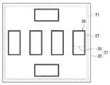
以上は、支持板32の貫通孔35を、別々の弾性部材41で取り囲む場合について説明したが、本発明はこれに限定されるものではなく、図10に示すように、支持板32の貫通孔35のうち、二以上を一つの弾性部材71で取り囲んでもよい。 The case where the through
1……真空処理装置 2……基板ホルダ 7……基板 11……真空槽 21……載置台 25……ガス供給路 30……基板保持装置 31……基板トレイ 32……支持板 35……貫通孔 41、71……弾性部材 61……温度制御手段 DESCRIPTION OF
Claims (7)
Translated fromJapanese前記真空槽内に配置される基板保持装置と、
前記基板保持装置が配置される載置台と、
前記基板保持装置上に乗せられる押圧板と、
前記押圧板を昇降させるピンと、
を有し、
前記基板保持装置は、
二以上の第一の貫通孔が形成された支持板と、
前記支持板の片面に配置された1又は複数のリング状の弾性部材とを有し、
各前記第一の貫通孔は前記弾性部材で取り囲まれ、
前記支持板の前記弾性部材とは反対側の面の各前記第一の貫通孔周囲の部分は、保持対象の基板が密着可能な着座部にされ、
各前記第一の貫通孔は前記弾性部材で取り囲まれ、前記弾性部材は、前記支持板の裏面と、前記載置台の表面と密着した状態で、前記載置台上に配置されるように構成され、
前記載置台には、前記弾性部材のリング内側の空間に熱媒体ガスを供給する供給路が設けられ、
前記押圧板は、前記載置台上の前記基板保持装置を覆うように、前記ピンに取り付けられ、
各前記第一の貫通孔上にそれぞれ前記基板を配置して各前記基板の裏面を前記第一の貫通孔内にそれぞれ露出させ、
前記押圧板によって前記基板保持装置を前記載置台に押し付けて前記弾性部材を前記載置台に密着させると、前記基板と前記載置台の間の空間が前記弾性部材によって密閉され、前記熱媒体ガスが密閉された前記空間に供給されるように構成された真空処理装置。A vacuum chamber;
A substrate holding device disposed in the vacuum chamber;
A mounting table on which the substrate holding device is disposed;
A pressing plate placed on the substrate holding device;
A pin for raising and lowering the pressing plate;
Have
The substrate holding device is
A support plate in which two or more first through holes are formed;
One or more ring-shaped elastic members disposed on one side of the support plate;
Each of the first through holes is surrounded by the elastic member,
A portion aroundeach of the first through holes on the surface of the support plate opposite to the elastic member is a seating portion to which a substrate to be held can be closely attached,
Each of the first through holes is surrounded by the elastic member, and the elastic member is configured to be disposed on the mounting table in close contact with the back surface of the support plate and the surface of the mounting table. ,
The mounting table is provided with a supply path for supplying a heat medium gas to a space inside the ring of the elastic member,
The pressing plate is attached to the pin so as to cover the substrate holding device on the mounting table,
Placing each of the substrates on each of the first through holes and exposing the back surface of each of the substrates in the first through holes,
When the substrate holding device is pressed against the mounting table by the pressing plate to bring the elastic member into close contact with the mounting table, a space between the substrate and the mounting table is sealed by the elastic member, and the heat medium gas is A vacuum processing apparatus configured to be supplied to the sealed space.
前記カバーには、各前記第一の貫通孔上に配置された前記基板の表面がそれぞれ露出される第二の貫通孔が設けられ、The cover is provided with a second through hole in which the surface of the substrate disposed on each first through hole is exposed,
前記ピンによって前記押圧板を降下させると、前記押圧板によって、前記カバーを介して前記支持板が押圧されて前記弾性部材が前記載置台に密着され、前記第二の貫通孔に露出する前記基板表面は、前記押圧板に設けられた第三の貫通孔内に露出される請求項1記載の真空処理装置。When the pressing plate is lowered by the pin, the supporting plate is pressed by the pressing plate through the cover, and the elastic member is brought into close contact with the mounting table, and is exposed to the second through hole. The vacuum processing apparatus according to claim 1, wherein the surface is exposed in a third through hole provided in the pressing plate.
各前記第一の貫通孔をそれぞれ覆うように、前記支持板の表面上に複数の前記基板をそれぞれ配置し、
各前記第一の貫通孔に前記基板の裏面が露出された状態で、前記第二の貫通孔内に露出する各前記基板の表面を真空処理する際に、
前記温度制御手段で前記載置台を加熱又は冷却しながら各前記基板の裏面の密閉された前記空間に前記熱媒体を供給し、前記基板温度を測定して前記熱媒体の温度を制御して、前記基板の温度を制御する基板の温度制御方法。Using the vacuum processing apparatus according to claim 6, a plurality of temperature ofthe substrate to a temperature control method of the substrate for controllingwhile vacuum processing,
A plurality of the substrates are respectively arranged on the surface of the support plate so as to covereach of the first through holes,
When the surface of each of the substrates exposed in the second through hole is vacuum-treated in a state where the back surface of the substrate is exposed in each of the first through holes,
Supplying the heat medium to the sealed space on the back surface of each substrate while heating or cooling the mounting table with the temperature control means, measuring the substrate temperature, and controlling the temperature of the heat medium, A substrate temperature control methodfor controlling a temperature of the substrate.
Priority Applications (1)
| Application Number | Priority Date | Filing Date | Title |
|---|---|---|---|
| JP2008040183AJP4997141B2 (en) | 2008-02-21 | 2008-02-21 | Vacuum processing apparatus and substrate temperature control method |
Applications Claiming Priority (1)
| Application Number | Priority Date | Filing Date | Title |
|---|---|---|---|
| JP2008040183AJP4997141B2 (en) | 2008-02-21 | 2008-02-21 | Vacuum processing apparatus and substrate temperature control method |
Publications (2)
| Publication Number | Publication Date |
|---|---|
| JP2009200241A JP2009200241A (en) | 2009-09-03 |
| JP4997141B2true JP4997141B2 (en) | 2012-08-08 |
Family
ID=41143434
Family Applications (1)
| Application Number | Title | Priority Date | Filing Date |
|---|---|---|---|
| JP2008040183AActiveJP4997141B2 (en) | 2008-02-21 | 2008-02-21 | Vacuum processing apparatus and substrate temperature control method |
Country Status (1)
| Country | Link |
|---|---|
| JP (1) | JP4997141B2 (en) |
Families Citing this family (9)
| Publication number | Priority date | Publication date | Assignee | Title |
|---|---|---|---|---|
| JP5144352B2 (en)* | 2008-04-22 | 2013-02-13 | 株式会社アルバック | Etching device |
| KR101160994B1 (en)* | 2010-09-01 | 2012-07-02 | 주식회사 테스 | A substrate processing apparatus |
| JP5873251B2 (en)* | 2011-04-28 | 2016-03-01 | キヤノンアネルバ株式会社 | Substrate tray and substrate processing apparatus using the tray |
| DE102012100929A1 (en)* | 2012-02-06 | 2013-08-08 | Roth & Rau Ag | Substrate processing system |
| CN103474322B (en)* | 2013-09-27 | 2016-08-17 | 广东尚能光电技术有限公司 | Dry etching equipment and lithographic method |
| JP2016069714A (en)* | 2014-10-01 | 2016-05-09 | 新日鐵住金株式会社 | Substrate holder, and film deposition apparatus equipped with the same |
| JP6270952B1 (en) | 2016-09-28 | 2018-01-31 | 株式会社日立国際電気 | Substrate processing apparatus, semiconductor device manufacturing method, and recording medium. |
| JP7582749B2 (en) | 2021-05-20 | 2024-11-13 | 東京エレクトロン株式会社 | Temperature control method and temperature control device |
| KR102598450B1 (en)* | 2021-06-23 | 2023-11-06 | 주식회사 엘에이티 | A sputtering process system for workpieces for eletromagnetic wave shielding |
Family Cites Families (4)
| Publication number | Priority date | Publication date | Assignee | Title |
|---|---|---|---|---|
| JPS62147340U (en)* | 1987-02-10 | 1987-09-17 | ||
| JPH0371626U (en)* | 1989-11-16 | 1991-07-19 | ||
| JP3640385B2 (en)* | 2001-12-26 | 2005-04-20 | 株式会社アルバック | Pyroelectric high-dielectric etching method and apparatus |
| JP4878109B2 (en)* | 2004-08-24 | 2012-02-15 | 株式会社アルバック | Substrate transfer system and substrate transfer method |
- 2008
- 2008-02-21JPJP2008040183Apatent/JP4997141B2/enactiveActive
Also Published As
| Publication number | Publication date |
|---|---|
| JP2009200241A (en) | 2009-09-03 |
Similar Documents
| Publication | Publication Date | Title |
|---|---|---|
| JP4997141B2 (en) | Vacuum processing apparatus and substrate temperature control method | |
| US8198567B2 (en) | High temperature vacuum chuck assembly | |
| JP6728196B2 (en) | Ceramic electrostatic chuck bonded to metal base by high temperature polymer bonding | |
| JP5274918B2 (en) | Method for controlling temperature of chamber inner member of plasma processing apparatus, chamber inner member and substrate mounting table, and plasma processing apparatus including the same | |
| US7922440B2 (en) | Apparatus and method for centering a substrate in a process chamber | |
| KR20210119296A (en) | Edge ring, substrate support, plasma processing system and method of replacing edge ring | |
| US20100122774A1 (en) | Substrate mounting table and substrate processing apparatus having same | |
| US20100163188A1 (en) | Mounting table structure and processing apparatus | |
| JP5886700B2 (en) | Heat transfer sheet sticking device and heat transfer sheet sticking method | |
| US11515130B2 (en) | Fast response pedestal assembly for selective preclean | |
| JP2019505088A (en) | Solutions for lifting wafer edge rings | |
| KR20100127200A (en) | Placement Structure and Processing Unit | |
| JP2008251742A (en) | Substrate treating apparatus, and substrate mounting base on which focus ring is mounted | |
| JP5981358B2 (en) | Heat transfer sheet affixing method | |
| JP2000124299A (en) | Semiconductor device manufacturing method and semiconductor manufacturing apparatus | |
| JP4992630B2 (en) | Mounting table structure and processing device | |
| JP2001127041A (en) | Substrate plasma processing apparatus and plasma processing method | |
| JP5247175B2 (en) | Vacuum processing equipment | |
| CN114026673B (en) | Heater Support Kit for Bevel Etch Chambers | |
| JP4518712B2 (en) | Tray-type multi-chamber substrate processing equipment | |
| JP2017022295A (en) | Plasma processing equipment | |
| KR20210157876A (en) | Plasma processing system, plasma processing apparatus, and method for replacing edge ring | |
| JPH05275385A (en) | Plasma processing device | |
| JP5838054B2 (en) | Plasma processing equipment | |
| KR101574779B1 (en) | Cap type electrostatic chuck having heater and method of manufacturing the same |
Legal Events
| Date | Code | Title | Description |
|---|---|---|---|
| A621 | Written request for application examination | Free format text:JAPANESE INTERMEDIATE CODE: A621 Effective date:20101112 | |
| A977 | Report on retrieval | Free format text:JAPANESE INTERMEDIATE CODE: A971007 Effective date:20111020 | |
| A131 | Notification of reasons for refusal | Free format text:JAPANESE INTERMEDIATE CODE: A131 Effective date:20111108 | |
| A521 | Request for written amendment filed | Free format text:JAPANESE INTERMEDIATE CODE: A523 Effective date:20111228 Free format text:JAPANESE INTERMEDIATE CODE: A821 Effective date:20111228 | |
| TRDD | Decision of grant or rejection written | ||
| A01 | Written decision to grant a patent or to grant a registration (utility model) | Free format text:JAPANESE INTERMEDIATE CODE: A01 Effective date:20120424 | |
| A01 | Written decision to grant a patent or to grant a registration (utility model) | Free format text:JAPANESE INTERMEDIATE CODE: A01 | |
| A61 | First payment of annual fees (during grant procedure) | Free format text:JAPANESE INTERMEDIATE CODE: A61 Effective date:20120514 | |
| FPAY | Renewal fee payment (event date is renewal date of database) | Free format text:PAYMENT UNTIL: 20150518 Year of fee payment:3 | |
| R150 | Certificate of patent or registration of utility model | Free format text:JAPANESE INTERMEDIATE CODE: R150 Ref document number:4997141 Country of ref document:JP Free format text:JAPANESE INTERMEDIATE CODE: R150 | |
| R250 | Receipt of annual fees | Free format text:JAPANESE INTERMEDIATE CODE: R250 | |
| R250 | Receipt of annual fees | Free format text:JAPANESE INTERMEDIATE CODE: R250 | |
| R250 | Receipt of annual fees | Free format text:JAPANESE INTERMEDIATE CODE: R250 | |
| R250 | Receipt of annual fees | Free format text:JAPANESE INTERMEDIATE CODE: R250 | |
| R250 | Receipt of annual fees | Free format text:JAPANESE INTERMEDIATE CODE: R250 | |
| R250 | Receipt of annual fees | Free format text:JAPANESE INTERMEDIATE CODE: R250 | |
| R250 | Receipt of annual fees | Free format text:JAPANESE INTERMEDIATE CODE: R250 | |
| R250 | Receipt of annual fees | Free format text:JAPANESE INTERMEDIATE CODE: R250 | |
| R250 | Receipt of annual fees | Free format text:JAPANESE INTERMEDIATE CODE: R250 |