JP4996702B2 - Chain saw - Google Patents
Chain sawDownload PDFInfo
- Publication number
- JP4996702B2 JP4996702B2JP2010016777AJP2010016777AJP4996702B2JP 4996702 B2JP4996702 B2JP 4996702B2JP 2010016777 AJP2010016777 AJP 2010016777AJP 2010016777 AJP2010016777 AJP 2010016777AJP 4996702 B2JP4996702 B2JP 4996702B2
- Authority
- JP
- Japan
- Prior art keywords
- chain
- saw
- guide bar
- tension
- brake
- Prior art date
- Legal status (The legal status is an assumption and is not a legal conclusion. Google has not performed a legal analysis and makes no representation as to the accuracy of the status listed.)
- Active
Links
Images


Classifications
- B—PERFORMING OPERATIONS; TRANSPORTING
- B27—WORKING OR PRESERVING WOOD OR SIMILAR MATERIAL; NAILING OR STAPLING MACHINES IN GENERAL
- B27B—SAWS FOR WOOD OR SIMILAR MATERIAL; COMPONENTS OR ACCESSORIES THEREFOR
- B27B17/00—Chain saws; Equipment therefor
- B27B17/14—Arrangements for stretching the chain saw
- B—PERFORMING OPERATIONS; TRANSPORTING
- B27—WORKING OR PRESERVING WOOD OR SIMILAR MATERIAL; NAILING OR STAPLING MACHINES IN GENERAL
- B27B—SAWS FOR WOOD OR SIMILAR MATERIAL; COMPONENTS OR ACCESSORIES THEREFOR
- B27B17/00—Chain saws; Equipment therefor
- B27B17/08—Drives or gearings; Devices for swivelling or tilting the chain saw
- B27B17/083—Devices for arresting movement of the saw chain
- Y—GENERAL TAGGING OF NEW TECHNOLOGICAL DEVELOPMENTS; GENERAL TAGGING OF CROSS-SECTIONAL TECHNOLOGIES SPANNING OVER SEVERAL SECTIONS OF THE IPC; TECHNICAL SUBJECTS COVERED BY FORMER USPC CROSS-REFERENCE ART COLLECTIONS [XRACs] AND DIGESTS
- Y10—TECHNICAL SUBJECTS COVERED BY FORMER USPC
- Y10T—TECHNICAL SUBJECTS COVERED BY FORMER US CLASSIFICATION
- Y10T83/00—Cutting
- Y10T83/707—By endless band or chain knife
- Y10T83/7226—With means to guard the tension
Landscapes
- Life Sciences & Earth Sciences (AREA)
- Engineering & Computer Science (AREA)
- Mechanical Engineering (AREA)
- Wood Science & Technology (AREA)
- Forests & Forestry (AREA)
- Sawing (AREA)
Description
Translated fromJapanese本発明は、チェンソーに関する。 The present invention relates to a chain saw.
従来、下記特許文献1に記載されるように、駆動力を伝達するための回転部を有する本体と、本体に装着されて本体の前方に延出するガイドバーと、回転部及びガイドバーの外縁部に沿って取り付けられる無終端状のソーチェンと、を備えるチェンソーにおいて、ガイドバーの孔に緊張部品を嵌入させ、この緊張部品をガイドバーの延出方向(前方)に押し出すコイルばねを有するソーチェンの張り機構が知られている。 Conventionally, as described in
この機構では、コイルばねの付勢力によりガイドバーをその延出方向に押し出し、ガイドバーに取り付けられたソーチェンに所定の張力を与えている。そして、押し出された状態のガイドバーを、ボルトの締結により本体に固定している。 In this mechanism, the guide bar is pushed in the extending direction by the urging force of the coil spring, and a predetermined tension is applied to the saw chain attached to the guide bar. And the guide bar of the extruded state is being fixed to the main body by fastening of the volt | bolt.
しかしながら、上記の機構では、コイルばねの付勢力のみによってガイドバーを押し出すようにしているため、十分な張力でソーチェンを張るにはコイルばねを強くする必要があり、その取り扱いが困難になるという問題があった。 However, in the above mechanism, since the guide bar is pushed out only by the urging force of the coil spring, it is necessary to strengthen the coil spring in order to stretch the saw chain with sufficient tension, which makes it difficult to handle. was there.
そこで本発明は、簡便にソーチェンを張ることができるチェンソーを提供することを目的とする。 Then, an object of this invention is to provide the chain saw which can stretch a saw chain simply.
本発明に係るチェンソーは、駆動力を伝達するための回転部(2)を有する本体(3)と、本体(3)に装着されて本体(3)の前方に延出するガイドバー(4)と、回転部(2)及びガイドバー(4)の外縁部に沿って取り付けられる無終端状のソーチェン(6)と、を備えるチェンソー(1)であって、ガイドバー(4)をガイドバー(4)の延出方向(A)に案内するための案内部(15)と、ガイドバー(4)に設けられ、ガイドバー(4)を厚み方向に貫通する孔部(4c)と、孔部(4c)に進入する係止突部(23)と、係止突部(23)を、操作者により操作される操作レバー(40)に連結する連結部(24)と、を有し、ガイドバー(4)の孔部(4c)に進入した係止突部(23)と共にガイドバー(4)が、操作レバー(40)の操作に連動して、延出方向(A)であってソーチェン(6)を張る方向に移動可能とされており、回転部(2)の回転を停止するためのブレーキ機構(46)を更に備え、操作レバー(40)は、回動支持部(41)を中心として第1の範囲(R1)を回動することにより、回動支持部(41)とは異なる位置にある軸(48)を中心として回動するブレーキ機構(46)の回動レバー(47)に当接しブレーキ機構(46)を操作可能であると共に、操作レバー(40)は、回動支持部(41)を中心とし第1の範囲(R1)とは異なる第2の範囲(R2)では、回動支持部(41)と軸(48)との位置の相違により回動レバー(47)から位置(P)で離脱し連結部(24)に連結されることを特徴とする。The chain saw according to the present invention includes a main body (3) having a rotating part (2) for transmitting a driving force, and a guide bar (4) attached to the main body (3) and extending forward of the main body (3). And a chain saw (1) that is attached along the outer edge of the rotating part (2) and the guide bar (4), the chain saw (1), the guide bar (4) being a guide bar ( 4) a guide portion (15) for guiding in the extending direction (A), a hole portion (4c) provided in the guide bar (4) and penetrating the guide bar (4) in the thickness direction, and a hole portion A locking protrusion (23) that enters (4c), and a connecting portion (24) that connects the locking protrusion (23) to an operation lever (40) operated by an operator, The guide bar (4), together with the locking protrusion (23) that has entered the hole (4c) of the bar (4), is In conjunction with the operation of chromatography (40), extending direction (A) a aare movable in the direction tensioning the saw chain(6), a brake mechanism for stopping the rotation of the rotating section (2) ( 46), and the operation lever (40) is located at a position different from the rotation support portion (41) by rotating the first range (R1) about the rotation support portion (41). The brake mechanism (46) can be operated by coming into contact with the rotation lever (47) of the brake mechanism (46) that rotates about the shaft (48), and the operation lever (40) is connected to the rotation support portion (41). ) In the second range (R2), which is different from the first range (R1), the position (from the rotation lever (47) due to the difference in position between the rotation support portion (41) and the shaft (48)). It is separated at P) and connected to the connecting part (24) .
本発明に係るチェンソーでは、ガイドバー(4)の孔部(4c)に進入した係止突部(23)は、連結部(24)によって操作レバー(40)に連結されており、この係止突部(23)が操作レバー(40)の操作に連動して延出方向(A)に沿って移動すると共に、この係止突部(23)の移動により、ガイドバー(4)が、案内部(15)により案内されながら延出方向(A)であってソーチェン(6)を張る方向に移動する。この際、ガイドバー(4)の外縁部に沿って取り付けられたソーチェン(6)の張力は、操作レバー(40)の操作により連結部(24)に伝わる力を調整することで、適宜調整することができる。よって、十分な張力でソーチェン(6)を張る場合であっても強いコイルばねを要するようなことがなく、簡便にソーチェン(6)を張ることができる。さらに、上記構成によれば、第1の範囲(R1)においてはブレーキ機構(46)によるブレーキ操作を支障なく行うことができ、また、第2の範囲(R2)においては操作レバー(40)の操作に連動してガイドバー(4)を移動させることによりソーチェン(6)の張り調整を支障なく行うことができる。In the chain saw according to the present invention, the locking protrusion (23) that has entered the hole (4c) of the guide bar (4) is connected to the operating lever (40) by the connecting portion (24). The protrusion (23) moves along the extending direction (A) in conjunction with the operation of the operation lever (40), and the guide bar (4) is guided by the movement of the locking protrusion (23). While being guided by the part (15), it moves in the extending direction (A) and the direction in which the saw chain (6) is stretched. Under the present circumstances, the tension | tensile_strength of the saw chain (6) attached along the outer edge part of a guide bar (4) is adjusted suitably by adjusting the force transmitted to a connection part (24) by operation of an operation lever (40). be able to. Therefore, even when the saw chain (6) is stretched with sufficient tension, a strong coil spring is not required, and the saw chain (6) can be easily stretched.Furthermore, according to the above configuration, the brake operation by the brake mechanism (46) can be performed without any trouble in the first range (R1), and the operation lever (40) can be operated in the second range (R2). By moving the guide bar (4) in conjunction with the operation, the tension of the saw chain (6) can be adjusted without any trouble.
ここで、連結部(24)は、操作レバー(40)に接続されたばね部材(26)を含む構成とすれば、ばね部材(26)の弾性によって、連結部(24)に伝わる力に対する緩衝作用が生じ、ソーチェン(6)の張力を略一定に調整することができる。 Here, if the connection portion (24) includes the spring member (26) connected to the operation lever (40), the buffer member acts on the force transmitted to the connection portion (24) by the elasticity of the spring member (26). Thus, the tension of the saw chain (6) can be adjusted to be substantially constant.
また、操作レバー(40)は、操作者の手を保護するためのハンドガードである構成とすれば、ソーチェン(6)の張り調整のための専用のレバーを別途設ける必要がなく部材の共用化が図られる。 Further, if the operation lever (40) is a hand guard for protecting the operator's hand, there is no need to separately provide a dedicated lever for adjusting the tension of the saw chain (6), and the members can be shared. Is planned.
また、連結部(24)は、その一端にU字部(26a,60a)を有する連結具(26,60)を含み、操作レバー(40)は、ピン(42)を有し、ピン(42)は、U字部(26a,60a)内に遊嵌配置されている構成とすれば、ソーチェン(6)の張り調整時以外の通常の使用時においては、U字部(26a,60a)内でピン(42)をフリーにすることができ連結部(24)による連結機能がはたらかず、鋸断作業を支障なく行うことができる。 The connection portion (24) includes a connection tool (26, 60) having a U-shaped portion (26a, 60a) at one end thereof, and the operation lever (40) has a pin (42), and the pin (42 ) In the U-shaped portion (26a, 60a), when it is in a normal use other than when adjusting the tension of the saw chain (6), Thus, the pin (42) can be made free, the connecting function by the connecting portion (24) does not work, and the sawing operation can be performed without any trouble.
また、ガイドバー(4)の基部(4a)を覆うように本体(3)に取り付けられるチェンケース(7)を備え、係止突部(23)、操作レバー(40)、及び連結部(24)は、チェンケース(7)に一体のユニットとして設けられている構成とすれば、ソーチェン(6)の張り調整に係るこれらの部品の組立が容易となる。 Moreover, the chain case (7) attached to the main body (3) so as to cover the base (4a) of the guide bar (4) is provided, and the locking projection (23), the operation lever (40), and the connecting portion (24). ) Is provided as an integral unit in the chain case (7), it is easy to assemble these parts for adjusting the tension of the saw chain (6).
本発明に係るチェンソーによれば、簡便な操作によりソーチェン張りを行うことができる。 According to the chain saw according to the present invention, the saw chain can be stretched by a simple operation.
以下、本発明の実施形態に係るチェンソーについて、図面を参照しながら説明する。なお、図面の説明において同一要素には同一符号を付し、重複する説明は省略する。 Hereinafter, a chain saw according to an embodiment of the present invention will be described with reference to the drawings. In the description of the drawings, the same elements are denoted by the same reference numerals, and redundant descriptions are omitted.
(第1実施形態)
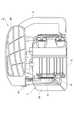
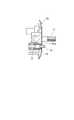
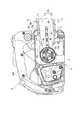
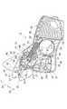
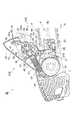
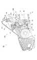
図1は、本発明の第1実施形態に係るチェンソーの右側面図、図2は、図1のチェンソーを前方から見た図、図3は、図1のチェンソーを構成する本体の右側面図である。(First embodiment)
1 is a right side view of the chain saw according to the first embodiment of the present invention, FIG. 2 is a view of the chain saw of FIG. 1 as viewed from the front, and FIG. 3 is a right side view of a main body constituting the chain saw of FIG. It is.
本実施形態のチェンソー1は、操作者により操作されて木材等の対象物を切るためのものであり、駆動力を伝達するための回転部2を有するチェンソー本体(本体)3と、チェンソー本体3に装着されてチェンソー本体3の前方(図1では右側)に延出するガイドバー4と、回転部2及びガイドバー4の外縁部に沿って取り付けられる無終端状のソーチェン6と、回転部2及びガイドバー4の基部4a(図5参照)を覆うようにチェンソー本体3に取り付けられるチェンケース7と、を備えている。本実施形態の説明においては、特に断らない限り、ガイドバー4の突出方向を前、チェンケース7の取り付け側を右とする。 The chain saw 1 of the present embodiment is for cutting an object such as wood, which is operated by an operator, and a chain saw body (main body) 3 having a rotating
回転部2は、チェンソー本体3に内蔵されたエンジンに連結されエンジンで生じた回転駆動力を伝達する略円筒形状のクラッチドラム2aと、クラッチドラム2aに設けられたスプロケット2bとを有している。ソーチェン6は、無終端状のチェーン6aに鋸刃6bを付けたものであり、このチェーン6aがスプロケット2bとガイドバー4の外周に掛け渡されている。 The rotating
このようなチェンソー1では、操作者がフロントハンドル8を左手で握ると共にリヤハンドル9の把手部9aを右手で握り、エンジンを駆動させることでスプロケット2bを回転させ、ソーチェン6を、スプロケット2b及びガイドバー4の外周により形成されている略長円形状の周回軌道を移動させることによって、道具を引くことなく対象物を切ることが可能になっている。 In such a chain saw 1, the operator grasps the
図4は、図3のIV-IV線断面図である。図3及び図4に示すように、チェンソー本体3の右側面には、回転部2の前方側において、ガイドバー4の基部4a(図5参照)をチェンソー本体3に取り付けるためのガイドプレート10が設けられている。ガイドプレート10には、その上下方向の中央部の位置において、前後方向に互いに離間するガイドバー取付ボルト11(以下、単に「ボルト11」ともいう)及びボルト12が、ガイドプレート10の表面10aに対して垂直に突出するようにして並設されている。 4 is a cross-sectional view taken along line IV-IV in FIG. As shown in FIGS. 3 and 4, a
更に、ガイドプレート10には、ガイドバー取付ボルト11及びボルト12の並設位置よりも下側において、ガイドバー4の延出方向Aに沿って延び、所定の上下幅を有する溝(溝部)14が形成されている。 Further, the
また、溝14内の後端部(図3の左側端部)には、先端側が閉じられた略円筒形状のキャップ(突起)16が、表面10aに対して垂直を成すように配置されており、このキャップ16の基端側(底部側)で溝14内には、当該キャップ16を外方へ付勢する圧縮スプリング17が設けられている。この状態で、キャップ16の先端側は、表面10aより所定長さ外方へ突出するように構成されている。 In addition, a substantially cylindrical cap (projection) 16 whose front end is closed is disposed at the rear end portion (left end portion in FIG. 3) in the
そして、このキャップ16は、後述するチェンケース7のボス(係止突部)23により、キャップ16の先端から基端に向けての押圧力を受けると、ガイドプレート10内に押し込まれてその先端が表面10aよりも内側に退避する(図6参照)。このように、キャップ16は、チェンソー本体3内に押込可能とされている。 When the
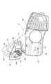
図5は、図3の本体3にガイドバー4を仮装着した状態を示す図である。図5に示すように、ガイドバー4には、ガイドバー4を厚み方向に貫通すると共にガイドバー4の延出方向Aに沿って延び、所定の上下幅を有する長孔部4bと、長孔部4bとは別に当該長孔部4bよりも下方の位置でガイドバー4を厚み方向に貫通する円形状の孔部4cとが設けられている。これらの長孔部4b及び孔部4cは、上記したボルト11,12及びキャップ16に対応する位置にそれぞれ設けられており、図5に示すガイドバー4の仮装着状態では、ボルト11,12は長孔部4bに挿入され、キャップ16は孔部4cに挿入される。 FIG. 5 is a view showing a state where the
上記構成により、キャップ16がチェンソー本体3から突出した状態となるガイドバー4の仮装着時には、当該キャップ16と、ボルト11,12とによって、ガイドバー4が3点(上下方向で見ると2点)で支持され、ガイドバー4が前方向に倒れたりガイドプレート10から脱落したりすることが防止され、仮装着時におけるガイドバー4の姿勢を安定にできる。また、キャップ16がチェンソー本体3内に押し込まれた状態では、ガイドバー4は、ボルト11,12及び長孔部4bにより案内され、ガイドプレート10上に摺接しながら延出方向Aに沿って移動できる。 With the above configuration, when the
斯くの如く、ガイドバー取付ボルト11、ボルト12、及び長孔部4bにより、ガイドバー4を延出方向Aに案内するための案内部15が構成されている。 As described above, the
また、図6に示すように、チェンソー本体3にチェンケース7が取り付けられ、ガイドバー取付ボルト11とナット18とが締結されることにより、ガイドバー4は、ガイドプレート10及びチェンケース7によって挟持固定される。なお、ソーチェン6を張り調整する場合には、ナット18を緩めることにより、ガイドバー4の姿勢を保持しつつガイドバー4の延出方向Aに沿う移動を許容することができる。 As shown in FIG. 6, the
図7は、図1中のチェンケース7を内側から見た図、図8は、図7のチェンケース7においてチェンブレーキが非作動の状態を示す図、図9は、図7のチェンケース7においてチェンブレーキを作動させた状態を示す図である。 7 is a view of the
図7〜図9に示すように、チェンケース7は、チェンソー本体3の右側面に取り付けられるケース本体20を備え、当該ケース本体20の上部に回動支持部41を介して回動可能に連結され操作者の手を保護するためのハンドガード40を有している(図1、図2も参照)。 As shown in FIGS. 7 to 9, the
このチェンケース7は、チェンソー1の使用中に回転部2の回転を停止するためのブレーキ機構であるチェンブレーキ46と、ソーチェン6の張力を調整するための張り調整機構であるチェン張り部21(図10参照)とを備えている。 The
ハンドガード40は、チェンブレーキ46を操作する機能を有すると共に、チェン張り部21の一部である操作レバーとしての機能を有している。このハンドガード40は、回動支持部41を中心として所定の範囲を回動可能とされている。より詳しくは、ハンドガード40は、下方の回動範囲(第1の範囲)R1(図9参照)を回動することによりチェンブレーキ46を操作可能となっており、回動範囲R1とは異なる上方の回動範囲(第2の範囲)R2を回動することによりチェン張り部21を操作可能となっている。 The
更に、ハンドガード40は、ハンドガード40の内側に設けられてチェンソー1の幅方向に所定長さ突出する丸棒状の第1ピン42及び第2ピン43を有している。 Further, the
第1ピン42は、図7において実線で示される通常の使用状態を基準として、ハンドガード40の前方側に配置され、第2ピン43は、第1ピン42よりも後方且つ僅かに上方に配置されている(図8参照)。第1ピン42は、チェンブレーキ46のブレーキを解除し、更には、ソーチェン6を張るためのものである。また、第2ピン43は、チェンブレーキ46のブレーキを作動させるためのものである。以下、チェンブレーキ46及びチェン張り部21について説明する。 The
まず、チェンブレーキ46について説明する。図8に示すように、チェンブレーキ46は、第2ピン43又は第1ピン42からの押圧作用を受けて軸48を中心に回動させられブレーキの作動又は解除を行うためのブレーキレバー(回動レバー)47と、ブレーキレバー47の基端側にその一端が連結されたリンク50と、円筒形状のスプリング収容部51内に配置され、リンク50の他端側を押圧する圧縮コイルばねであるブレーキスプリング52と、ブレーキスプリング52の伸張に伴い回転部2(図5参照)を制動するブレーキリング53とを有している。 First, the
ブレーキレバー47は、ハンドガード40の回動範囲R1(図9参照)において、軸48よりも上部に延びたピン当接部49が、第1ピン42及び第2ピン43の間に位置するように設けられており、ハンドガード40の下降操作に伴い第2ピン43により上方から摺接(当接)状態で押し下げられることによりブレーキを作動させ、一方、ハンドガード40の上昇操作に伴い第1ピン42により下方から摺接(当接)状態で押し上げられることによりブレーキを解除させる。 The
ここで、ピン当接部49の回動中心である軸48は、第1ピン42の回動中心である回動支持部41とは異なる位置に設けられている。このような回動支持部41と軸48との位置の相違により、第1ピン42の回動軌跡とピン当接部49先端の回動軌跡とは、ブレーキレバー47のブレーキ解除位置付近で交差するようになっている(図9の位置P参照)。そのため、ハンドガード40の上昇操作によって、ピン当接部49先端より下方に位置する第1ピン42により押し上げられたブレーキレバー47は、その後、位置Pにおいて第1ピン42から離脱する構成とされている。換言すれば、ハンドガード40は、回動範囲R1ではブレーキレバー47に当接するが、第1ピン42の位置が離脱位置Pよりも上方側となる回動範囲R2では、ブレーキレバー47から離脱する構成とされている。 Here, the
ブレーキリング53は、回転部2(図5参照)のクラッチドラム2aの外周に着脱自在に巻回された部材であり、一端がブレーキスプリング52の先端側(上端側)に設けられた掛止部55に接続され、他端がケース本体20側に設けられた掛止部80に固定されている。このブレーキリング53は、図8に示すブレーキ非作動状態では、クラッチドラム2aから離隔されて回転部2の回転を許容し、図9に示すブレーキ作動状態では、ブレーキスプリング52の伸張に従いクラッチドラム2aを締め付けて回転部2を制動する。 The
ここで、ブレーキスプリング52は、ブレーキスプリング52の押圧力とリンク50の壁56への当接により、ブレーキ非作動の状態でその位置(姿勢)を保持するようになっている。よって、ハンドガード40の下降操作又は上昇操作によってチェンブレーキ46のブレーキを作動又は解除するためには、ブレーキスプリング52の姿勢保持力を上回る程度の強い力でハンドガード40を操作すれば良い。なお、上記チェンブレーキ46では、チェンソー1使用時の跳ね返り現象である所謂キックバックが発生した場合にハンドガード40が左手により強く押し下げられ、チェンソー1が非常停止するようになっている。 Here, the
続いて、チェン張り部21について、図10も参照しながら説明する。図10は、チェンソー1のチェン張り部21によるソーチェン6の張り調整の動作概念図である。図10に示すように、チェン張り部21は、操作者により操作される操作レバーとしてのハンドガード40と、チェンケース7の内側面に設けられた内側カバー19(図6及び図7参照)の開口部25(図7参照)からチェンソー本体3に向けて突出し、ガイドバー4の孔部4c(図5参照)に進入するソーチェン張り調整用のボス23と、ボス23をハンドガード40に連結する連結部24とを有している。これらのハンドガード40、ボス23、及び連結部24は、チェンケース7に一体のユニットとして設けられている。 Next, the
ボス23は、チェンケース7の内側カバー19から所定長さだけ突出している。このボス23は、その突出長さが、図6に示すようにガイドバー4の厚みよりも長くされ、チェンケース7をチェンソー本体3に装着した状態でガイドバー4の孔部4cに進入し、更には、キャップ16が設けられた溝14内に進入するようになっている。 The
連結部24は、その上端がハンドガード40の第1ピン42に接続され、所定のばね定数を有する引張コイルばねである連結スプリング(ばね部材)26と、その一端が連結スプリング26の下端に連結され軸29を中心に回動自在に設けられた第1リンク27と、第1リンク27の他端に対し連結軸31を介して回動可能に連結され、前方の端部に前述したボス23が設けられた第2リンク28とを有している。 The connecting
連結スプリング26は、ハンドガード40の操作により引っ張られて第1リンク27を図8及び図9の時計周りに回動させ,この回動により第2リンク28と共にボス23を前方に移動させるための連結具である。連結スプリング26は、その上端部(一端)において、コイルばね部分の軸線よりも後方に屈曲したU字部26aを有している(図7、図10参照)。このU字部26aは、コイルばね部分から延びる線材とU字状に折り返された線材とにより形成されており、折り返された線材の終端はコイルばね部分の上端付近まで戻ると共に当該上端からは所定距離だけ離間している。そして、このU字部26a内に、上記した第1ピン42が遊嵌配置され、U字部26a内を長手方向に往復移動可能とされている。 The
図7において実線で示される通常の使用状態では、ハンドガード40の第1ピン42はU字部26a内の長手方向中央部に位置しているが、仮想線で示すように、ハンドガード40の上昇操作に伴い第1ピン42がU字部26a内を上昇し、U字部26aの長手方向上端部内側に係合する。この係合により、連結スプリング26は第1ピン42により引っ張り上げられるようになっている。このようにして、ハンドガード40は、第1ピン42により連結スプリング26に対し接続されている。 In a normal use state indicated by a solid line in FIG. 7, the
なお、第1ピン42がU字部26aの長手方向上端部内側に係合する位置は、上述したブレーキレバー47の第1ピン42からの離脱位置P(第1ピン42の回動軌跡とピン当接部49先端の回動軌跡とが交差する位置P;図9参照)と同程度の位置とされている。すなわち、第1ピン42がブレーキレバー47から離脱する回動範囲R2では、第1ピン42とU字部26aとの係合により、ハンドガード40は連結スプリング26を引っ張り上げることが可能となっている。これによって、回動範囲R2ではハンドガード40が連結部24に連結され、ソーチェン6の張り作業時(図10の仮想線から実線への移動時)には、第1ピン42はブレーキレバー47に干渉せず、張り作業が支障なく行われる。 The position where the
連結部24を構成する第1リンク27は、その上端27aが連結スプリング26の下端に対し回転自在に連結され、軸29の位置を屈折点として前方に向けて上方に傾くように屈折している。この第1リンク27は、連結スプリング26からの引張力を受けて図10の反時計回りに回動し、第2リンク28と共にボス23を前方(図10の延出方向A)に押し出す。 The
第2リンク28は、図8及び図9に示すように、ケース本体20の内側に形成された長手方向に垂直な断面が溝状のガイド部22により案内されて、ガイド部22内を前後方向に移動可能に設けられている。ガイド部22の後端及び前端には、第2リンク28の移動範囲を規制するための後方壁36及び前方壁37が形成されている。 As shown in FIGS. 8 and 9, the
ここで、上記第1リンク27には、ボス23を図8に実線で示す初期位置Bに移動するためのねじりばね32が取り付けられている。より詳しくは、ねじりばね32は、その一端がケース本体20の内側に形成された係止部33に係止され、軸29の周りを下側から一又は複数巻きした上で、他端が第1リンク27の下部27bに対し前方から引っ掛けられている。 Here, a
このような構成により、チェン張り部21では、ねじりばね32により第1リンク27の下部27bが後方に付勢されて後方壁36に当接すると共に、この状態でボス23が初期位置Bに位置する。この初期位置Bは、チェンケース7をチェンソー本体3に装着する際にチェンソー本体3に設けられたキャップ16(図3、図5参照)に対面する位置となっている。そして、これらの第1リンク27、第2リンク28、ガイド部22、ねじりばね32、及び後方壁36を含んで、ボス23を初期位置Bに移動させる移動手段34が構成されている。 With such a configuration, in the
従って、ボス23は、ハンドガード40に連結されてハンドガード40の動きと連動し、移動手段34による後方への付勢力に抗して、ソーチェン6を張るために必要な最低限の前進位置であるチェン最短位置Cや、このチェン最短位置Cから、前方壁37により規制される最前位置に至るまでの所定範囲の調整位置Dを移動可能とされている(図8参照)。 Accordingly, the
以上の構成を有するチェンソー1では、ガイドバー4をチェンソー本体3に仮装着するにあたって、ガイドバー4に設けられた長孔部4b及び孔部4cの各々に、チェンソー本体3に設けられたボルト11,12及びキャップ16を挿入する。ここで、ボルト11,12及びキャップ16の位置は、長孔部4b及び孔部4cの各々に予め対応しているため、位置合わせの手間を要せず、ガイドバー4を容易に仮装着することができる。 In the chain saw 1 having the above configuration, when the
そして、チェンケース7を、図1に示すようにチェンソー本体3に取り付けることにより、移動手段34により初期位置Bに移動された状態のボス23が、ガイドバー4の孔部4c及びチェンソー本体3の溝14に進入し、キャップ16をチェンソー本体3内に押し込む(図6参照)。 Then, by attaching the
キャップ16は、このように、チェンソー本体3内に押し込まれることによりガイドバー4の孔部4cから退避(離脱)しているため、案内部15(ボルト11,12及び長孔部4b)によってガイドバー4を延出方向Aに案内しながらソーチェン6の張り調整を行うことができる。 Since the
より詳しくは、ハンドガード40を回動範囲R2(図9参照)内で上方に向けて回動操作することにより、この操作に連動して連結スプリング26が引っ張られて伸張しつつ、第1リンク27を回動させ、この回動により、ガイドバー4の孔部4cに進入したボス23が溝14内を延出方向Aに移動し、このボス23の移動に伴い、ガイドバー4が延出方向Aであってソーチェン6を張る方向に移動する(図10の実線参照)。 More specifically, by rotating the
ここで、連結スプリング26のばね定数とソーチェン6の張り抵抗とのバランスにより、ハンドガード40を上方へ所定の回動位置まで回動させることによってソーチェン6は所望の張力に調整される。例えば、ソーチェン6の張り抵抗が大きい場合には、ハンドガード40を所定の回動位置から更に上方に向けて回動させても、連結スプリング26が伸張するのみで第1リンク27、第2リンク28、及びボス23はほとんど移動しなくなり、そのためソーチェン6の張力は誰がハンドガード40を操作しても略一定に保たれる。そして、ソーチェン6を張り終えた後、ナット18を締めてガイドバー4を挟持固定する。 Here, the
また、チェンソー1の使用時において、例えばキックバック等が発生し操作者の左手によりハンドガード40が強く押し下げられる(下方に回動させられる)と、チェンブレーキ46のブレーキレバー47が第2ピン43により押し下げられてブレーキが作動し、図9の実線で示す状態となる。 Further, when the chain saw 1 is used, for example, when a kickback or the like occurs and the
また、ブレーキが作動した後、ハンドガード40が上方に向けて回動操作されると、ブレーキレバー47が第1ピン42により押し上げられてブレーキが解除され、図8に示す状態となる。 When the
以上説明した本実施形態のチェンソー1によれば、ソーチェン6の張り調整を行う際、ガイドバー4の外縁部に沿って取り付けられたソーチェン6の張力は、ハンドガード40の操作により連結部24に伝わる力を調整することで、適宜調整することができる。よって、十分な張力でソーチェン6を張る場合であっても強いコイルばねを要するようなことがなく、簡便にソーチェンを張ることができる。 According to the chain saw 1 of the present embodiment described above, when the tension of the
また、連結部24は、ハンドガード40に接続された連結スプリング26を含むため、連結スプリング26の弾性によって連結部24に伝わる力に対する緩衝作用が生じ、ソーチェン6の張力を略一定に調整することができる。 In addition, since the connecting
また、ハンドガード40は、操作者の手を保護するためのハンドガードであるため、ソーチェン6の張り調整のための専用のレバーを別途設ける必要がなく部材の共用化が図られる。 Moreover, since the
また、ハンドガード40は、回動支持部41を中心として回動範囲R1を回動することにより軸48を中心として回動するブレーキレバー47に当接しチェンブレーキ46を操作可能であると共に、ハンドガード40は、回動範囲R1とは異なる回動範囲R2では、回動支持部41と軸48との位置の相違によりブレーキレバー47から離脱位置Pで離脱し連結部24に連結されるため、回動範囲R1においてはチェンブレーキ46によるブレーキ操作を支障なく行うことができ、また、回動範囲R2においてはハンドガード40の操作に連動してガイドバー4を移動させることによりソーチェン6の張り調整を支障なく行うことができる。すなわち、ブレーキ操作及びソーチェン6の張り調整を各々独立して行うことができる。 Further, the
また、ハンドガード40の第1ピン42は、連結スプリング26のU字部26a又は連結具60のU字部60a内に遊嵌配置されているため、ソーチェン6の張り調整時以外の通常の使用時においては、U字部26a,60a内で第1ピン42をフリーにすることができ連結部24による連結機能がはたらかず、鋸断作業を支障なく行うことができる。 Further, since the
また、ボス23、ハンドガード40、及び連結部24は、チェンケース7に一体のユニットとして設けられているため、ソーチェン6の張り調整に係るこれらの部品の組立が容易となる。 In addition, since the
また、連結スプリング26の弾性(ばね定数)によりソーチェン6の張力が決まるので、操作者によらず誰でも同程度の張り調整が行えると共に、ソーチェン6の張り強さのバラツキが無くなることにより安全性が向上し、ソーチェン6の張り過ぎによるガイドバー4、ソーチェン6の短寿命化を防止でき、更には、ソーチェン6の張り不足によるガイドバー4の損傷やソーチェン6の脱落を防止できる。 Further, since the tension of the
また、チェン張り部21によって迅速かつ確実にソーチェン6の張り調整を行うことができると共に、ソーチェン6の初期伸びが発生する新品のソーチェン6使用時に必要となる頻繁なソーチェン6の張り調整に際しても、鋸断作業の停止時間を最小限に抑えつつ張り調整を行うことができる。 In addition, the
更にまた、精密部品や歯車等を用いずにばね等の汎用技術でチェン張り部21を構成できるため、製造コストを抑えることができる。 Furthermore, since the
(第2実施形態)
図11は、第2実施形態に係るチェンソーのチェン張り部によるソーチェンの張り調整の動作概念図である。図11に示す本実施形態のチェンソー1Aが図10に示した第1実施形態のチェンソー1と違う点は、チェンブレーキ46を備えていない点である。このチェンソー1Aにおいても、チェン張り部21によって、チェンソー1と同様のソーチェン6の張り調整を行うことができ、チェンソー1と同様の作用・効果を得ることができる。(Second Embodiment)
FIG. 11 is an operation conceptual diagram of the tension adjustment of the saw chain by the chain tension portion of the chain saw according to the second embodiment. The chain saw 1A of the present embodiment shown in FIG. 11 is different from the chain saw 1 of the first embodiment shown in FIG. 10 in that the
(第3実施形態)
図12は、第3実施形態に係るチェンソーのチェン張り部によるソーチェンの張り調整の動作概念図である。図12に示す本実施形態のチェンソー1Bが図10に示した第1実施形態のチェンソー1と違う点は、連結スプリング26に代えて樹脂製の連結具60を用いた点である。なお、この変更に伴い、連結部24及びチェン張り部21は、連結部24B及びチェン張り部21Bに変更されている。(Third embodiment)
FIG. 12 is an operation conceptual diagram of tension adjustment of the saw chain by the chain tension portion of the chain saw according to the third embodiment. The chain saw 1B of the present embodiment shown in FIG. 12 is different from the chain saw 1 of the first embodiment shown in FIG. 10 in that a
この連結具60は、連結スプリング26のU字部26aと同様の形状を成すU字部60aを有しており、このU字部60a内に、ハンドガード40の第1ピン42が遊嵌配置されている。チェン張り部21Bのその他の構成は、チェンソー1のチェン張り部21と同様である。 The connecting
このチェンソー1Bにおいても、チェン張り部21Bによって、チェンソー1と同様のソーチェン6の張り調整を行うことができる。なお、チェン張り部21Bの連結具60によれば、ハンドガード40を引き上げる強さ(回動位置の高さ)に応じて、ソーチェン6の張力を調整することができる。 Also in this chain saw 1B, the tension adjustment of the
(第4実施形態)
図13は、第4実施形態に係るチェンソーのチェン張り部によるソーチェンの張り調整の動作概念図である。図13に示す本実施形態のチェンソー1Cが図12に示した第3実施形態のチェンソー1Bと違う点は、チェンブレーキ46を備えていない点である。このチェンソー1Cにおいても、チェン張り部21Bによって、チェンソー1Bと同様のソーチェン6の張り調整を行うことができる。(Fourth embodiment)
FIG. 13: is an operation | movement conceptual diagram of the tension adjustment of the saw chain by the chain tension part of the chain saw which concerns on 4th Embodiment. The chain saw 1C of the present embodiment shown in FIG. 13 is different from the chain saw 1B of the third embodiment shown in FIG. 12 in that the
以上、本発明の実施形態について説明したが、本発明は、上記実施形態に限られるものではない。例えば、上記実施形態では、チェン張り部21は、チェンケース7に一体のユニットとして設けられている場合について説明したが、チェンソー本体3側に設けられていてもよい。また、連結部24は、連結スプリング26や連結具60を有する構成に限られず、リンク機構のみにより構成されていてもよい。 As mentioned above, although embodiment of this invention was described, this invention is not limited to the said embodiment. For example, in the above embodiment, the
1,1A,1B,1C…チェンソー、2…回転部、3…チェンソー本体、4…ガイドバー、4a…基部、4c…孔部、6…ソーチェン、7…チェンケース、15…案内部、23…ボス(係止突部)、24,24B…連結部、26…連結スプリング(ばね部材)、26a…U字部、40…ハンドガード(操作レバー)、41…回動支持部、42…第1ピン(ピン)、46…チェンブレーキ(ブレーキ機構)、47…ブレーキレバー(回動レバー)、48…軸、60…連結具、60a…U字部、A…延出方向、P…離脱位置(位置)、R1…回動範囲(第1の範囲)、R2…回動範囲(第2の範囲)。 1, 1A, 1B, 1C ... chain saw, 2 ... rotating part, 3 ... chain saw body, 4 ... guide bar, 4a ... base, 4c ... hole, 6 ... saw chain, 7 ... chain case, 15 ... guide part, 23 ... Boss (locking protrusion), 24, 24B ... connecting part, 26 ... connecting spring (spring member), 26a ... U-shaped part, 40 ... hand guard (operating lever), 41 ... rotation support part, 42 ... first Pin (pin), 46 ... Chain brake (brake mechanism), 47 ... Brake lever (rotating lever), 48 ... Shaft, 60 ... Connector, 60a ... U-shaped part, A ... Extension direction, P ... Release position ( Position), R1... Rotation range (first range), R2... Rotation range (second range).
Claims (5)
Translated fromJapanese前記ガイドバー(4)を前記ガイドバー(4)の延出方向(A)に案内するための案内部(15)と、
前記ガイドバー(4)に設けられ、前記ガイドバー(4)を厚み方向に貫通する孔部(4c)と、
前記孔部(4c)に進入する係止突部(23)と、
前記係止突部(23)を、操作者により操作される操作レバー(40)に連結する連結部(24)と、を有し、
前記ガイドバー(4)の前記孔部(4c)に進入した前記係止突部(23)と共に前記ガイドバー(4)が、前記操作レバー(40)の操作に連動して、前記延出方向(A)であってソーチェン(6)を張る方向に移動可能とされており、
前記回転部(2)の回転を停止するためのブレーキ機構(46)を更に備え、
前記操作レバー(40)は、回動支持部(41)を中心として第1の範囲(R1)を回動することにより、前記回動支持部(41)とは異なる位置にある軸(48)を中心として回動する前記ブレーキ機構(46)の回動レバー(47)に当接し前記ブレーキ機構(46)を操作可能であると共に、
前記操作レバー(40)は、前記回動支持部(41)を中心とし前記第1の範囲(R1)とは異なる第2の範囲(R2)では、回動支持部(41)と軸(48)との位置の相違により回動レバー(47)から位置(P)で離脱し前記連結部(24)に連結されることを特徴とするチェンソー。A main body (3) having a rotating part (2) for transmitting a driving force, a guide bar (4) attached to the main body (3) and extending forward of the main body (3), and the rotating part A chain saw (1) comprising (2) and an endless saw chain (6) attached along the outer edge of the guide bar (4),
A guide portion (15) for guiding the guide bar (4) in the extending direction (A) of the guide bar (4);
A hole (4c) provided in the guide bar (4) and penetrating the guide bar (4) in the thickness direction;
A locking projection (23) that enters the hole (4c);
A connecting portion (24) for connecting the locking projection (23) to an operating lever (40) operated by an operator;
The guide bar (4), together with the locking projection (23) that has entered the hole (4c) of the guide bar (4), moves in the extending direction in conjunction with the operation of the operation lever (40). (A) is movable in the direction of stretching the saw chain (6),
A brake mechanism (46) for stopping the rotation of the rotating part (2);
The operating lever (40) has a shaft (48) located at a position different from the rotation support portion (41) by rotating in the first range (R1) about the rotation support portion (41). The brake mechanism (46) that rotates about the center of the brake mechanism (46) abuts on the rotation lever (47) and can be operated,
In the second range (R2), which is different from the first range (R1), the operation lever (40) is centered on the rotation support portion (41). The chain sawis separated from the rotating lever (47) at the position (P) due to the difference in position with respect to the connecting portion (24) .
前記操作レバー(40)は、ピン(42)を有し、
前記ピン(42)は、前記U字部(26a,60a)内に遊嵌配置されていることを特徴とする請求項1〜3のいずれか一項記載のチェンソー。The connecting part (24) includes a connecting tool (26, 60) having a U-shaped part (26a, 60a) at one end thereof,
The operating lever (40) has a pin (42),
The chain saw according to any one of claims 1 to3 , wherein the pin (42) is loosely arranged in the U-shaped part (26a, 60a).
前記係止突部(23)、前記操作レバー(40)、及び前記連結部(24)は、前記チェンケース(7)に一体のユニットとして設けられていることを特徴とする請求項1〜4のいずれか一項記載のチェンソー。A chain case (7) attached to the main body (3) so as to cover the base (4a) of the guide bar (4);
The locking projection (23), said operating lever (40), and the connecting portion (24), according to claim1-4, characterized in that is provided as an integral unit in the chain case (7) The chain saw according to any one of the above.
Priority Applications (4)
| Application Number | Priority Date | Filing Date | Title |
|---|---|---|---|
| JP2010016777AJP4996702B2 (en) | 2010-01-28 | 2010-01-28 | Chain saw |
| ES11152293.4TES2670230T3 (en) | 2010-01-28 | 2011-01-27 | Chainsaw |
| US13/015,205US8549761B2 (en) | 2010-01-28 | 2011-01-27 | Chain saw |
| EP11152293.4AEP2353812B1 (en) | 2010-01-28 | 2011-01-27 | Chain Saw |
Applications Claiming Priority (1)
| Application Number | Priority Date | Filing Date | Title |
|---|---|---|---|
| JP2010016777AJP4996702B2 (en) | 2010-01-28 | 2010-01-28 | Chain saw |
Publications (2)
| Publication Number | Publication Date |
|---|---|
| JP2011152750A JP2011152750A (en) | 2011-08-11 |
| JP4996702B2true JP4996702B2 (en) | 2012-08-08 |
Family
ID=43896868
Family Applications (1)
| Application Number | Title | Priority Date | Filing Date |
|---|---|---|---|
| JP2010016777AActiveJP4996702B2 (en) | 2010-01-28 | 2010-01-28 | Chain saw |
Country Status (4)
| Country | Link |
|---|---|
| US (1) | US8549761B2 (en) |
| EP (1) | EP2353812B1 (en) |
| JP (1) | JP4996702B2 (en) |
| ES (1) | ES2670230T3 (en) |
Families Citing this family (3)
| Publication number | Priority date | Publication date | Assignee | Title |
|---|---|---|---|---|
| CN105459213B (en)* | 2016-01-13 | 2017-08-25 | 大连丰和金瑞设备制造有限公司 | The continuous stock-cutter of the full specification of numerical control |
| JP6583436B2 (en)* | 2016-01-30 | 2019-10-02 | 工機ホールディングス株式会社 | Chain saw |
| USD1018234S1 (en)* | 2021-07-12 | 2024-03-19 | Westcoast Saw, Llc | Pair of felling dogs |
Family Cites Families (19)
| Publication number | Priority date | Publication date | Assignee | Title |
|---|---|---|---|---|
| US3457970A (en)* | 1966-11-09 | 1969-07-29 | Omark Industries Inc | Self-tensioning chain devices |
| JPS471949Y1 (en) | 1969-06-24 | 1972-01-24 | ||
| US3636995A (en)* | 1970-07-02 | 1972-01-25 | Textron Inc | Tensioner for saw chain |
| SE7506347L (en)* | 1975-06-04 | 1976-12-05 | Partner Ab | DEVICE FOR MOTORSAWS |
| JPS6039201A (en) | 1983-08-10 | 1985-03-01 | Mitsubishi Electric Corp | Manual operating device |
| JPH03128689A (en) | 1989-10-11 | 1991-05-31 | Fanuc Ltd | Torque fluctuation observer |
| JPH03128689U (en)* | 1990-04-05 | 1991-12-25 | ||
| FR2763013B1 (en)* | 1997-05-06 | 1999-07-16 | Bernard Barbe | CHAIN TENSION AND SAFETY MECHANISM FOR CHAINSAW |
| US6944958B1 (en)* | 2000-11-06 | 2005-09-20 | King William C | Chain saw chain tensioning and braking system |
| WO2004103657A1 (en)* | 2003-05-20 | 2004-12-02 | Komatsu Zenoah Co. | Auto chain tensioner |
| JP2006015606A (en)* | 2004-07-01 | 2006-01-19 | Kioritz Corp | Saw chain tensioning device |
| US7434502B2 (en)* | 2004-07-21 | 2008-10-14 | Husqvarna Outdoor Products Inc. | Bar knob with cam-operated locking mechanism |
| GB0515970D0 (en)* | 2005-08-03 | 2005-09-07 | Bosch Gmbh Robert | Chain saw |
| US7350301B2 (en)* | 2005-08-25 | 2008-04-01 | Hsin-Chih Chung Lee | Tension-adjusting device for a chain in chain saw |
| US7743513B1 (en)* | 2006-10-31 | 2010-06-29 | Mtd Products Inc | Chainsaw tensioning device |
| FR2913076B1 (en)* | 2007-02-26 | 2010-10-22 | Pellenc Sa | CLAMPING DEVICE WITH RETRACTABLE SHAFT ARM AND APPARATUS INCLUDING THE SAME |
| EP2408600B1 (en)* | 2009-03-18 | 2015-11-04 | Husqvarna Ab | Chainsaw comprising a quick tensioning unit and a guide bar |
| JP5297290B2 (en)* | 2009-07-23 | 2013-09-25 | 株式会社やまびこ | Chain saw |
| JP5486325B2 (en)* | 2010-01-21 | 2014-05-07 | 株式会社丸山製作所 | Chain saw |
- 2010
- 2010-01-28JPJP2010016777Apatent/JP4996702B2/enactiveActive
- 2011
- 2011-01-27USUS13/015,205patent/US8549761B2/enactiveActive
- 2011-01-27ESES11152293.4Tpatent/ES2670230T3/enactiveActive
- 2011-01-27EPEP11152293.4Apatent/EP2353812B1/enactiveActive
Also Published As
| Publication number | Publication date |
|---|---|
| US20110179653A1 (en) | 2011-07-28 |
| ES2670230T3 (en) | 2018-05-29 |
| JP2011152750A (en) | 2011-08-11 |
| EP2353812A1 (en) | 2011-08-10 |
| EP2353812B1 (en) | 2018-03-07 |
| US8549761B2 (en) | 2013-10-08 |
Similar Documents
| Publication | Publication Date | Title |
|---|---|---|
| EP2106888B1 (en) | Chain saw | |
| JP5086569B2 (en) | Bicycle derailleur control device | |
| US8627572B2 (en) | Coasting brake arrangement for a power tool | |
| US11104026B2 (en) | Chain and bar cassette and chainsaw guide bar with tension indicator | |
| EP1759944B1 (en) | Parking brake apparatus | |
| JP4996702B2 (en) | Chain saw | |
| WO2004103657A1 (en) | Auto chain tensioner | |
| US20100218388A1 (en) | Chainsaw throttle and brake mechanisms | |
| JP2011218550A (en) | Bevel adjustment device for circular saw | |
| EP0538066B1 (en) | Miter saw | |
| JP2009154895A (en) | Binding machine for horticulture | |
| JP5486325B2 (en) | Chain saw | |
| US7331111B2 (en) | Chainsaw throttle and brake mechanisms | |
| JP2005328847A (en) | Brake system for power tool | |
| US20070011888A1 (en) | Chainsaw throttle and brake mechanisms | |
| US4246701A (en) | Safety braking device for a portable power saw | |
| JP2016182790A (en) | Brake device of chain-saw | |
| JP4438640B2 (en) | Telescopic operation device | |
| JP4051057B2 (en) | Parking brake device | |
| JP2007505779A (en) | Steering column device | |
| JP2010133532A (en) | Braking device for chain saw, and chain saw | |
| JP2009153418A (en) | Horticultural binder | |
| JP4484454B2 (en) | Parking brake device | |
| JP4638809B2 (en) | Seedling planting equipment | |
| JP2011025470A (en) | Chain saw |
Legal Events
| Date | Code | Title | Description |
|---|---|---|---|
| A621 | Written request for application examination | Free format text:JAPANESE INTERMEDIATE CODE: A621 Effective date:20111104 | |
| A131 | Notification of reasons for refusal | Free format text:JAPANESE INTERMEDIATE CODE: A131 Effective date:20111206 | |
| A521 | Request for written amendment filed | Free format text:JAPANESE INTERMEDIATE CODE: A523 Effective date:20120131 | |
| TRDD | Decision of grant or rejection written | ||
| A01 | Written decision to grant a patent or to grant a registration (utility model) | Free format text:JAPANESE INTERMEDIATE CODE: A01 Effective date:20120508 | |
| A01 | Written decision to grant a patent or to grant a registration (utility model) | Free format text:JAPANESE INTERMEDIATE CODE: A01 | |
| A61 | First payment of annual fees (during grant procedure) | Free format text:JAPANESE INTERMEDIATE CODE: A61 Effective date:20120511 | |
| FPAY | Renewal fee payment (event date is renewal date of database) | Free format text:PAYMENT UNTIL: 20150518 Year of fee payment:3 | |
| R150 | Certificate of patent or registration of utility model | Free format text:JAPANESE INTERMEDIATE CODE: R150 Ref document number:4996702 Country of ref document:JP Free format text:JAPANESE INTERMEDIATE CODE: R150 |