JP4996481B2 - Ignition device, gas generator for airbag, and gas generator for seat belt pretensioner - Google Patents
Ignition device, gas generator for airbag, and gas generator for seat belt pretensionerDownload PDFInfo
- Publication number
- JP4996481B2 JP4996481B2JP2007553007AJP2007553007AJP4996481B2JP 4996481 B2JP4996481 B2JP 4996481B2JP 2007553007 AJP2007553007 AJP 2007553007AJP 2007553007 AJP2007553007 AJP 2007553007AJP 4996481 B2JP4996481 B2JP 4996481B2
- Authority
- JP
- Japan
- Prior art keywords
- ignition device
- heating element
- gas generator
- asic
- ignition
- Prior art date
- Legal status (The legal status is an assumption and is not a legal conclusion. Google has not performed a legal analysis and makes no representation as to the accuracy of the status listed.)
- Expired - Fee Related
Links
Images


Classifications
- F—MECHANICAL ENGINEERING; LIGHTING; HEATING; WEAPONS; BLASTING
- F42—AMMUNITION; BLASTING
- F42B—EXPLOSIVE CHARGES, e.g. FOR BLASTING, FIREWORKS, AMMUNITION
- F42B3/00—Blasting cartridges, i.e. case and explosive
- F42B3/10—Initiators therefor
- F42B3/12—Bridge initiators
- F42B3/121—Initiators with incorporated integrated circuit
- F42B3/122—Programmable electronic delay initiators
- B—PERFORMING OPERATIONS; TRANSPORTING
- B60—VEHICLES IN GENERAL
- B60R—VEHICLES, VEHICLE FITTINGS, OR VEHICLE PARTS, NOT OTHERWISE PROVIDED FOR
- B60R21/00—Arrangements or fittings on vehicles for protecting or preventing injuries to occupants or pedestrians in case of accidents or other traffic risks
- B60R21/02—Occupant safety arrangements or fittings, e.g. crash pads
- B60R21/16—Inflatable occupant restraints or confinements designed to inflate upon impact or impending impact, e.g. air bags
- B60R21/26—Inflatable occupant restraints or confinements designed to inflate upon impact or impending impact, e.g. air bags characterised by the inflation fluid source or means to control inflation fluid flow
- B60R2021/26029—Ignitors
Landscapes
- Engineering & Computer Science (AREA)
- Computer Hardware Design (AREA)
- Microelectronics & Electronic Packaging (AREA)
- General Engineering & Computer Science (AREA)
- Air Bags (AREA)
- Feeding, Discharge, Calcimining, Fusing, And Gas-Generation Devices (AREA)
Description
Translated fromJapanese本発明は、エアバッグ等の自動車の安全装置に使用されるガス発生器等に搭載される点火装置およびかかる点火装置を搭載したエアバッグ用ガス発生装置およびシートベルトプリテンショナー用ガス発生装置に関するものである。 The present invention relates to an ignition device mounted on a gas generator or the like used in a safety device of an automobile such as an airbag, an airbag gas generator mounted with the ignition device, and a gas generator for a seat belt pretensioner. It is.
自動車に装着されるエアバッグを膨張させるためのガス発生器用の点火装置として、従来から種々の電気式点火装置が開発されている。
この点火装置は、通常、外部と電気的に接続するための金属ピンを有し、またこの金属ピンの他端には火薬に点火するための加熱素子をそなえている。
かような加熱素子としては、特許文献1およびこれに対応する特許文献2に開示されているような、プリントサブサーキットに組み込まれた加熱素子が知られている。Conventionally, various electric ignition devices have been developed as an ignition device for a gas generator for inflating an airbag mounted on an automobile.
This ignition device usually has a metal pin for electrically connecting to the outside, and a heating element for igniting explosives at the other end of the metal pin.
As such a heating element, a heating element incorporated in a print subcircuit as disclosed in
また、一方で、エアバッグシステムをLAN化して通信により点火装置の点火をコントロールすることが考えられている。
この場合には、特許文献3に記載されているように、通信および点火のための電気回路を点火装置内に設置する必要がある。On the other hand, it is considered to control the ignition of the ignition device by communication using LAN as an airbag system.
In this case, as described in
従って、上記のような構造になる点火装置では、内蔵する電気回路に通電するための手段が必要となる。
例えば、特許文献4には、電気回路基板を塞栓の電極ピンにハンダ等で固定した構造が示されている。Therefore, the ignition device having the above-described structure requires means for energizing the built-in electric circuit.
For example, Patent Document 4 shows a structure in which an electric circuit board is fixed to an electrode pin of an embolus with solder or the like.
内部に通信および点火のための電気回路を組み込んだ構造の点火装置において、誤発火を防止するためには、内部の電気回路に対する外部からの電磁波ノイズや電磁誘導を遮断できれば良い。 In an ignition device having a structure in which an electric circuit for communication and ignition is incorporated inside, in order to prevent erroneous ignition, it is only necessary to block electromagnetic noise and electromagnetic induction from the outside with respect to the internal electric circuit.
また、内部に電気回路を組み込んだ構造の点火装置では、従来、特許文献4に開示されているように、予め基板に回路を構成し、塞栓の電極ピンと結合後、樹脂でモールドしなければならなかった。
しかしながら、特に塞栓と接続した状態での樹脂モールドは、通常のICなどリードフレームに固定された部品のモールドに比べると著しく生産性が低い。
また、電極ピンと電気回路の接続をハンダでしっかり固定した場合には、残留応力に起因したハンダ割れの発生が懸念される。
さらに、電極ピンと電気回路の接続を頑強に行うためにはある程度の接続部長さが必要となるため、元々体積の小さい点火装置の中でこのような構造を採用すると点火装置が大きなものとなり、ガス発生器に搭載する際、サイズの増大を招くという問題もある。Moreover, in an ignition device having a structure in which an electric circuit is incorporated inside, as disclosed in Patent Document 4, a circuit is previously formed on a substrate, bonded to an embolic electrode pin, and then molded with a resin. There wasn't.
However, the resin mold particularly in a state where it is connected to the embolus is remarkably less productive than the mold of a part fixed to a lead frame such as a normal IC.
Further, when the connection between the electrode pin and the electric circuit is firmly fixed with solder, there is a concern that solder cracking due to residual stress may occur.
Furthermore, since a certain length of connecting portion is required to make the connection between the electrode pin and the electric circuit robust, when such a structure is adopted in an ignition device having a small volume, the ignition device becomes large and the gas When mounted on the generator, there is also a problem of increasing the size.
本発明は、上記の実情に鑑み開発されたもので、内部に電気回路を組み込んだ構造になる点火装置において、内部電気回路に対する外部からの電磁波ノイズ等を効果的に遮断することができる点火装置を提案することを目的とする。
また、本発明は、樹脂モールドの製造に際して生産性を低下させることがなく、またサイズの増大を招くことがなく、しかも点火装置に内蔵された電気回路への通電が確実な点火装置を提案することを目的とする。
さらに、本発明は、上記した電磁波ノイズ等のシールド性が高くかつコンパクトな点火装置を搭載したエアバッグ用ガス発生装置を提案することを目的とする。The present invention has been developed in view of the above circumstances, and in an ignition device having a structure in which an electric circuit is incorporated, an ignition device capable of effectively blocking electromagnetic noise from the outside to the internal electric circuit. The purpose is to propose.
In addition, the present invention proposes an ignition device that does not decrease productivity in the production of a resin mold, does not increase in size, and reliably energizes an electric circuit built in the ignition device. For the purpose.
Furthermore, an object of the present invention is to propose a gas generator for an air bag equipped with a compact ignition device having high shielding properties such as electromagnetic noise.
さて、発明者らは、まず、点火装置の内部に組み込んだ電気回路を誤動作させないために、電磁波ノイズ等を遮断する手段について検討した。
その結果、内部電気回路の周囲を金属製のカップ体で覆うと共に、このカップ体を金属製の塞栓と一体化し、さらにこの塞栓の周囲にフランジを設け、このフランジを点火装置の設置体(例えばインフレータ)のハウジングに接続してやれば、点火装置の内部が効果的にシールドされ、かつ点火装置自体を電気的にガス発生装置を介してグランドに落とすことができるとの知見を得た。
また、フランジをハウジングに接続する際、カシメにより接続すれば、フランジを設置体に対して強固に固定できると共に、ガス発生装置の作動時の圧力にも十分に耐え得るとの知見を得た。The inventors first examined means for blocking electromagnetic wave noise and the like in order to prevent malfunction of an electric circuit incorporated in the ignition device.
As a result, the periphery of the internal electric circuit is covered with a metal cup body, the cup body is integrated with a metal embolus, and a flange is provided around the embolus. It has been found that if it is connected to the housing of the inflator, the inside of the ignition device is effectively shielded and the ignition device itself can be electrically dropped to the ground via the gas generator.
In addition, when connecting the flange to the housing, it has been found that if the connection is made by caulking, the flange can be firmly fixed to the installation body and can sufficiently withstand the pressure during operation of the gas generator.
さらに、発明者らは、電極ピンと電気回路の接続方法に関して鋭意検討を重ねた結果、以下に述べる知見を得た。
a)塞栓の電極ピンを切り離し、ASIC等の電気回路のみ樹脂でモールドすることにより、樹脂モールドの製造を生産性よく行うことができる。
b)電極ピンと樹脂モールド内の電気回路との接続は、該樹脂モールドに設けた通信電極を介して接触により行う。これにより、電極ピンと電気回路の接続が容易となる上に、点火装置の体積を小さく保つことができる。Furthermore, as a result of intensive studies on the method of connecting the electrode pins and the electric circuit, the inventors have obtained the following knowledge.
a) By cutting off the electrode pins of the embolus and molding only the electric circuit such as ASIC with resin, the resin mold can be manufactured with high productivity.
b) The connection between the electrode pin and the electric circuit in the resin mold is performed by contact via a communication electrode provided in the resin mold. Thereby, the connection between the electrode pin and the electric circuit is facilitated, and the volume of the ignition device can be kept small.
但し、樹脂モールドに設けた通信電極に軽く接触する程度の力で塞栓の電極ピンを押し付けただけでは、点火装置が衝撃を受けた場合に、通信電極と電極ピンの接続が切断される場合があることが判明した。
そこで、この点に関し、さらに検討を重ねた結果、
c)点火装置のカップ体と塞栓は最終的には溶接により一体化するのであるが、この溶接を、点火装置のカップ体に塞栓を一定以上の圧力で押し込んだ状態で行えば、電気回路を包む樹脂モールドとカップ体の弾性反力によって通信電極と電極ピンの接合は押圧接合となり、かような押圧接合下では、点火装置がかなりの力で衝撃を受けた場合でも、通信電極と電極ピンの接続が切断されることはない。
d)さらに、上記したような押圧接合とすれば、樹脂モールドとカップ体の弾性反力は点火薬と加熱素子間にも作用するため、樹脂モールドの他端に設けた加熱素子と火薬が圧接状態で接合することになり、その結果、確実な点火と点火時間の短縮化が達成される。
本発明は、上記の知見に立脚するものである。However, if the electrode pin of the embolus is simply pressed with a force that makes light contact with the communication electrode provided on the resin mold, the connection between the communication electrode and the electrode pin may be disconnected when the ignition device is impacted. It turned out to be.
Therefore, as a result of further examination on this point,
c) The cup body and the plug of the igniter are finally integrated by welding, but if this welding is performed with the plug being pushed into the cup body of the igniter with a certain pressure or more, the electric circuit is Due to the elastic reaction force between the encapsulating resin mold and the cup body, the connection between the communication electrode and the electrode pin becomes a pressure bond. Under such a pressure bond, even if the ignition device is subjected to an impact with a considerable force, the communication electrode and the electrode pin Will never be disconnected.
d) Furthermore, if the above-described pressure bonding is used, the elastic reaction force between the resin mold and the cup body also acts between the igniting agent and the heating element, so that the heating element provided at the other end of the resin mold and the explosive are pressed. As a result, reliable ignition and shortening of the ignition time are achieved.
The present invention is based on the above findings.
すなわち、本発明の要旨構成は次のとおりである。
(1)金属製のカップ体と、複数の電極ピンをそれぞれ絶縁して保持し、該カップ体の開口部を封じて一体化する金属製の塞栓をそなえ、該カップ体の内部には、点火薬、ASIC、コンデンサーおよび加熱素子を有し、該ASICは、該電極ピン、該コンデンサーおよび該加熱素子とそれぞれ電気的に接続され、さらに該加熱素子が該点火薬に当接してなる点火装置において、
上記したASIC、コンデンサーおよび加熱素子を、該ASICと該コンデンサーが基盤に搭載され、該基盤が樹脂でモールドされた樹脂モールドの頭部に該ASICと接続された加熱素子を有し、またその底部には該ASICと該電極ピンを接続するための通信電極を配設したASICコンポーネントとして有すると共に、
該塞栓の外周部に、点火装置の設置体に固定するための金属製のフランジをそなえることを特徴とする点火装置。That is, the gist configuration of the present invention is as follows.
(1) A metal cup body and a plurality of electrode pins are respectively insulated and held, and a metal embolus for sealing and integrating the opening of the cup body is provided. In an ignition device having an explosive, an ASIC, a condenser, and a heating element, wherein the ASIC is electrically connected to the electrode pin, the condenser, and the heating element, and the heating element is in contact with the ignition charge. ,
The ASIC, the condenser and the heating element described above have the heating element connected to the ASIC on the top of the resin mold in which the ASIC and the condenser are mounted on the base, and the base is molded with resin, and the bottom of the base. Has a communication electrode for connecting the ASIC and the electrode pin as an ASIC component,
An ignition device comprising a metal flange for fixing to an installation body of an ignition device on an outer peripheral portion of the embolus.
(2)上記(1)において、前記電極ピンと前記通信電極を押圧接合としたことを特徴とする点火装置。(2 ) The ignition device according to (1 ), wherein the electrode pin and the communication electrode are press-bonded.
(3)上記(1)または(2)において、前記加熱素子と前記火薬は圧接してなることを特徴とする点火装置。(3 ) The ignition device according to (1)or (2) , wherein the heating element and the explosive are in pressure contact.
(4)上記(1)〜(3)のいずれかにおいて、前記加熱素子の上面に点火薬組成物を塗布することを特徴とする点火装置。(4 ) The ignition device according to any one of (1) to (3 ), wherein an igniter composition is applied to the upper surface of the heating element.
(5)上記(1)〜(4)のいずれかにおいて、前記加熱素子はSCBチップからなることを特徴とする点火装置。(5 ) In any one of the above (1) to (4 ), the heating element is an SCB chip.
(6)上記(5)において、前記SCBチップは、金属と絶縁物を積層したブリッジを含むことを特徴とする点火装置。(6 ) In the above (5 ), the SCB chip includes a bridge in which a metal and an insulator are laminated.
(7)上記(1)〜(6)のいずれかに記載した点火装置に設けた前記フランジを、カシメまたは溶接により、ガス発生器が有する点火装置の設置体の金属部に電気的に接続しつつ固定したことを特徴とするエアバッグ用ガス発生装置。(7 ) The flange provided in the ignition device described in any one of (1) to (6 ) above is electrically connected to a metal part of the installation body of the ignition device included in the gas generator by caulking or welding. A gas generator for an air bag which is fixed while being fixed.
(8)上記(1)〜(6)のいずれかに記載した点火装置に設けた前記フランジを、カシメまたは溶接により、ガス発生器が有する点火装置の設置体の金属部に電気的に接続しつつ固定したことを特徴とするシートベルトプリテンショナー用ガス発生装置。(8 ) The flange provided in the ignition device described in any of (1) to (6 ) above is electrically connected to a metal part of the installation body of the ignition device included in the gas generator by caulking or welding. A gas generator for a seat belt pretensioner, which is fixed while being fixed.
本発明の効果を列挙すると次のとおりである。
(1) 点火装置内部の電気回路に対する外部からの電磁波ノイズや電磁誘導を効果的に遮断することができるので、内部電気回路の誤動作ひいては誤発火を防止することができる。
(2) 点火装置を設置体に強固に固定することができ、しかもガス発生装置の作動時における圧力にも十分に耐え得る。
(3) 設置体が高温に曝された場合であっても、固定部分に樹脂を使用しないので熱による軟化が少ないため、バーストの発生がなく、安全である。
(4) 樹脂でモールドするのはASIC等の電気回路のみなので、樹脂モールドの生産性が向上する。
(5) 点火装置の外部モールドを必要としないので、点火装置の製造工程を1工程省略することができ、その分点火装置を安価に製造することができる。The effects of the present invention are listed as follows.
(1) Since electromagnetic noise and electromagnetic induction from the outside with respect to the electric circuit inside the ignition device can be effectively cut off, it is possible to prevent malfunction of the internal electric circuit and thus false ignition.
(2) The ignition device can be firmly fixed to the installation body and can sufficiently withstand the pressure during operation of the gas generator.
(3) Even when the installation body is exposed to a high temperature, since no resin is used for the fixed part, there is little softening due to heat, so there is no burst and it is safe.
(4) Since only electrical circuits such as ASIC are molded with resin, the productivity of resin molding is improved.
(5) Since an external mold for the ignition device is not required, one step of manufacturing the ignition device can be omitted, and the ignition device can be manufactured at that cost.
さらに、好ましい態様とすることにより、以下の効果が得られる。
(6) 電気回路と電極ピンとの接合は、樹脂モールドの底部に設けた通信電極と電極ピンとの押圧接合により行うので、点火装置自体をコンパクト化することができ、また組み立ても簡便化される。
(7) 通信電極と電極ピンとを押圧接合とすることにより、点火装置がかなりの力で衝撃を受けた場合でも、通信電極と電極ピンの接続が切断されることはない。
(8) 上記の押圧接合を介して、加熱素子と火薬が圧接接合となるので、確実な点火と点火時間の短縮化が達成される。Furthermore, the following effects are acquired by setting it as a preferable aspect.
(6) Since the electrical circuit and the electrode pin are joined by pressing the communication electrode provided at the bottom of the resin mold and the electrode pin, the ignition device itself can be made compact and assembly can be simplified.
(7) By making the communication electrode and the electrode pin press-bonded, the connection between the communication electrode and the electrode pin is not disconnected even when the ignition device receives an impact with a considerable force.
(8) Since the heating element and the explosive are pressure-bonded through the above-described press bonding, reliable ignition and shortening of the ignition time are achieved.
1 カップ体
2 点火薬
2′伝火薬
2″点火薬組成物
3 ASICコンポーネント
4 ASIC
5 コンデンサー
6 加熱素子
7 通信電極
8 塞栓
9 電極ピン
10 ガラス封止
11 フランジ
12 点火用電極
13 ハウジング
21 エアバッグ用ガス発生装置
22 点火装置
23 エンハンサー剤
24 ガス発生剤
25 フィルター
26 外郭容器
27 孔
31 シートベルトプリテンショナー用ガス発生装置(マイクロガスジェネレータ)
32 点火装置
33 ガス発生剤
34 基台(ホルダー)
35 カップ体
110 中央制御ユニット
111a〜111d エアバッグモジュール
114,115 電極ピン1
5
10 Glass sealing
11 Flange
12 Ignition electrode
13 Housing
21 Gas generator for airbags
22 Ignition system
23 Enhancer
24 Gas generant
25 filters
26 Outer container
27 holes
31 Gas generator for seat belt pretensioner (micro gas generator)
32 Ignition system
33 Gas generant
34 Base (holder)
35 cup body
110 Central control unit
111a to 111d airbag module
114,115 electrode pin
以下、本発明を具体的に説明する。
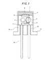
図1に、本発明に従う点火装置を断面図で示す。図中、番号1は金属製のカップ体、2は点火薬である。3は、ASICやコンデンサーなど電気回路に必要な素子を搭載した基盤を樹脂でモールドしたASICコンポーネントであり、図中4がASIC、5がコンデンサーである。ここに、ASIC(Application Specific Integrated Circuit)4とは、特定用途向け集積回路のことで、本発明では、外部と相互通信してコード化された情報に基づいて点火装置を点火する相互通信スイッチ手段として機能する。また、コンデンサー5は、電気エネルギーの蓄積手段として機能する。
そして、6は、ASICコンポーネント3の頭部に設置した加熱素子、7は、同じくASICコンポーネント3の底部に配設した通信電極である。なお、ASICコンポーネント3の基盤としては、リードフレームを使うこともできる。Hereinafter, the present invention will be specifically described.
FIG. 1 shows a cross-sectional view of an ignition device according to the present invention. In the figure,
また、8は金属製の塞栓であり、この塞栓8には、外部と電気的に接続するための電極ピン9がガラス封止10によって固定されている。このようにガラス封止によって電極ピンを固定することにより、高い気密性を保ちながら電気的絶縁を確保することができる。さらに、金属製カップ体と塞栓金属部が溶接されることで、カップ体の内部は高い気密性の下でシールされる。そして、11が塞栓8の外周部に設けられた金属製のフランジである。フランジ用金属の好適例としては、例えばステンレススチール、ニッケル鉄およびニッケルめっきされたSPCなど鉄系のものが挙げられる。
さて、本発明では、まず、カップ体1の最深部に粉末状の点火薬2を配置する。この点火薬2は、図1に示したように、一種類の火薬の一層配置としてもよいが、図2に示すように、点火薬2の外側により伝火力の強い伝火薬2′を配置した二層構造とするのがより有利である。
ここに、伝火薬2′としては、その組成中にジルコニウムを含むものが好適である。その他、水素化チタンやボロン、トリシネートなどを含むものも有利に適合する。
また、点火薬2としては、上記したものの他に、例えば特願2001−140468号明細書や特開2002−362992号公報に開示のものが使用でき、特に限定されるものではない。
そして、かかる点火薬2に接触させて加熱素子6を配置する。
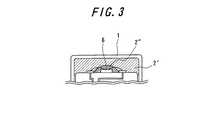
この際、加熱素子の上面に、図3に示すような点火薬組成物2″を塗布することが、加熱素子と点火薬の接触をより安定化させる上で有利である。In the present invention, first, the
Here, as the
In addition to the above, the
And the
At this time, it is advantageous to apply the
かような加熱素子6としては、低エネルギーでの着火が可能ないわゆるSCBチップが有利に適合する。また、かかるSCBチップを、金属と絶縁物を積層したブリッジ構造とすれば、低エネルギーで大きな火花を発生させることができるので一層有利である。
ここに、SCBとは、Semiconductor Bridgeのことで、通常の半導体ICの製造工程を使用して作製された加熱素子をいう。As such a
Here, SCB is a Semiconductor Bridge, which is a heating element manufactured using a normal semiconductor IC manufacturing process.
上記のブリッジ構造としては、チタン、ニッケルクロム合金、ニッケル、アルミニウム、マグネシウムおよびジルコニウムの組と、カルシウム、マンガン、二酸化珪素およびシリコンの組から選ばれた各1種以上の組成物を交互に積層したものを適用することもできる。
好ましいブリッジ構造としては、シリコン基板上に、チタンとSiO2(またはボロン)を交互に積層したものが有利に適合する。各層の厚みは、それぞれ0.05〜10μm 程度とするのが好ましい。より好ましい膜厚は0.1〜4μm である。
なお、加熱素子6に対する電気的接続は、ASICコンポーネント3の上面に設けた点火用電極12を介して行う。As the above bridge structure, a set of titanium, nickel chromium alloy, nickel, aluminum, magnesium and zirconium and one or more compositions each selected from the set of calcium, manganese, silicon dioxide and silicon were alternately laminated. Things can also be applied.
As a preferable bridge structure, a structure in which titanium and SiO2 (or boron) are alternately laminated on a silicon substrate is advantageously suitable. The thickness of each layer is preferably about 0.05 to 10 μm. A more preferable film thickness is 0.1 to 4 μm.
The electrical connection to the
本発明におけるASICコンポーネント3中には、相互通信と特定の電気パルスの列をトリガするための手段としてのASIC4と電気エネルギー蓄積手段としてコンデンサー5が内蔵されている。
なお、このASICコンポーネント3は、2本の電極ピン9を介して、後述する中央制御ユニットに連絡しているLAN化されたエアバッグシステムに統合される。In the
The
また、このASICコンポーネント3は、円筒形カップ1の内径に沿う大きさの円柱形状として、該カップ1内への挿入をスムーズに行う必要がある。そのためには、ASICコンポーネント3の外径はカップ内径の85%以上、99%以下程度とすることが好ましい。 Further, the
ここに、ASICコンポーネント3の底部に配設した通信電極7の直径は、電極ピン9の直径よりも幾分小さくして、組み立て時の公差等により、通信電極7と電極ピン9の接触位置が幾分ズレたとしても、両者が常に接合状態を維持し、電気的接続を保持できるようにすることが好ましい。
また、通信電極7と電極ピン9との接触部分は、平坦にしておくことが、強く押し付けたときに安定した接触を可能とする上で有利である。Here, the diameter of the
In addition, it is advantageous to make the contact portion between the
本発明では、上述したように、カップ体1の最深部に、点火薬2を充填したのち、ASICコンポーネント3を、その頭部に配置した加熱素子6が点火薬2に当接するように挿入し、ついで該ASICコンポーネント3の底部に配設した通信電極7に、塞栓8に設けた電極ピン9が当接するように挿入したのち、カップ体1と塞栓8とを溶接して一体化する。 In the present invention, as described above, after filling the deepest portion of the
かくすることにより、ASICを含む点火装置の内部が導電性のある金属体で覆われていて、フランジを介してガス発生装置に固定されることになるので、電磁波ノイズ等の効果的なシールドが可能となる。
また、溶接して一体化することにより、内部の気密性が保持される。
さらに、点火装置全体が金属体で覆われることにより、ガス発生装置が輸送中に火災等に遭遇し、高温下に曝された場合であっても、バーストの発生がなく、安全である。
この点、従来の点火装置は、プラスチックで絶縁を保っていたため、火災に遭遇した場合にはどうしても樹脂部が軟化し、ガス発生剤が作動したときの内圧で吹き飛ばされ、飛散する可能性があり、これを防止するため特別な工夫をする必要があった。By doing so, the inside of the ignition device including the ASIC is covered with a conductive metal body and is fixed to the gas generator through the flange, so that an effective shield such as electromagnetic noise can be obtained. It becomes possible.
Moreover, the internal airtightness is maintained by welding and integrating.
Furthermore, since the entire ignition device is covered with a metal body, even if the gas generator encounters a fire during transportation and is exposed to high temperatures, it does not generate a burst and is safe.
In this respect, since the conventional ignition device kept insulation with plastic, the resin part inevitably softens in the event of a fire, and may be blown away and scattered by the internal pressure when the gas generating agent is activated It was necessary to devise special measures to prevent this.
また、カップ体1と塞栓8の溶接による一体化に際しては、かかる溶接を、カップ体1内に塞栓8を圧入した状態で行うことが好ましい。
すなわち、塞栓8をカップ体1内に一定以上の圧力で押し込んだ状態で溶接を行えば、樹脂でモールドされたASICコンポーネント3とカップ体1の弾性反力によって通信電極7と電極ピン9の接合は押圧接合となり、その結果、点火装置がかなりの力で衝撃を受けた場合でも、通信電極7と電極ピン9との接続の切断が有利に回避されるのである。Moreover, when integrating the
That is, if welding is performed in a state where the
また、通信電極7と電極ピン9の接合を、上記したような押圧接合とすれば、ASICコンポーネント3とカップ体1の弾性反力は反対側にも作用するため、該ASICコンポーネント3の反対側に設けた加熱素子6が点火薬2と圧接状態で接合する、すなわち点火薬2の密度が向上することになるので、確実な点火と点火時間の有利な短縮化が達成されるのである。
さらに、上記のような押圧接合は、接続部をハンダや溶接で固定する構造に比べて簡便なだけでなく、接続に必要な体積がほとんど不要という利点もある。Further, if the
Furthermore, the above press bonding is not only simpler than the structure in which the connecting portion is fixed by soldering or welding, but also has an advantage that almost no volume necessary for connection is required.
ここに、上記した塞栓8のカップ体1内への圧入力は1〜250 MPa程度とすることが好ましい。というのは、圧入力が1MPaに満たないと通信電極7と電極ピン9の接合に十分な押圧力が得られず、一方250 MPaを超えるとASICコンポーネントに加わる応力が大きくなりすぎて、ASICコンポーネントが破損する危険があるからである。なお、より好ましい圧入力は2〜130 MPaの範囲である。 Here, the pressure input into the
また、本発明では、図3に示すように、加熱素子6の上面に、予め点火薬組成物2″を塗布しておくこともできる。すなわち、加熱素子6の上面にスラリー状の点火薬をディスペンスし、乾燥させる。この点火薬組成物2″は、粉末状の点火薬を単に充填した場合に比べると点火薬と加熱素子の接触が安定であるため、確実な点火と点火時間の短縮化に有効に寄与する。 In the present invention, as shown in FIG. 3, the
本発明の点火装置を、設置体内例えばインフレータ内に設置する場合には、図4に示すように、かしめを利用して、フランジ11をインフレータのハウジング13と直接接合することが望ましい。なお、接続方法としては、上記したかしめの他、溶接も有利に適合する。
というのは、上記の構成にすれば、点火装置の内部が効果的にシールドされ、かつ点火装置自体をインフレータを介して電気的にグランドすることができるからである。When the ignition device of the present invention is installed in an installation body, for example, in an inflator, it is desirable to join the
This is because with the above configuration, the interior of the ignition device is effectively shielded, and the ignition device itself can be electrically grounded via the inflator.
また、本発明の点火装置は、ASICコンポーネント3を、気密に保たれた塞栓8とカップ1の内側に設置でき、通信電極7と電極ピン8の電気的な接続を接触によって保持できるので、ASICコンポーネント3を搭載しているにもかかわらず、点火装置1の外形寸法を従来の点火装置に近いものとすることができる。
さらに、本発明の点火装置は、ASICコンポーネント3に内蔵させた、相互通信スイッチ手段としてのASIC4および電気エネルギー蓄積手段としてコンデンサー5を使用することにより、外部(例えば中央制御ユニット)と連絡することができる。In the ignition device of the present invention, the
Furthermore, the ignition device of the present invention can communicate with the outside (for example, the central control unit) by using the ASIC 4 incorporated in the
従って、例えば、自動車に組み込まれるエアバッグモジュールであって、LAN化されたエアバッグシステムを介して中央制御ユニットに接続されるエアバッグモジュールの各々にこのような点火装置を使用することは、衝突時に中央制御ユニットが所望のエアバッグモジュールのみを点火させることを可能にし、またかような点火装置を起爆させるための特別な電気エネルギーを送ることも不要となる。
このような作用効果は特に、各点火装置に、中央制御ユニットより発せられた電圧信号に含まれる微弱なエネルギーを蓄積するコンデンサー5を設け、従来よりも低いエネルギーで点火することができるSCBチップを加熱素子6として使用し、また中央制御ユニットから来るコード化された情報を検出しかつ点火装置の状態を送るコマンドを送信することができる相互通信および点火スイッチ手段とてしのASIC4を設けることにより達成される。Thus, for example, the use of such an ignition device for each of the airbag modules incorporated in an automobile and connected to the central control unit via a LAN-enabled airbag system is a collision. Sometimes it is possible for the central control unit to ignite only the desired airbag module, and it is not necessary to send special electrical energy to initiate such an igniter.
In particular, such an operational effect is provided with a capacitor 5 for storing weak energy included in the voltage signal generated by the central control unit in each ignition device, and an SCB chip that can be ignited with lower energy than before. By providing an ASIC 4 as an intercommunication and ignition switch means which can be used as a
なお、本発明において、中央制御ユニットとの相互通信で使用されるコード化された情報とは、各点火装置を点火するコマンドを含む情報、および各点火装置に含まれる電子的要素の状態を中央制御ユニットに伝える情報の両者を意味する。 In the present invention, the coded information used for mutual communication with the central control unit means information including a command for igniting each ignition device, and a state of an electronic element included in each ignition device. It means both information to be transmitted to the control unit.
次に、本発明の点火装置を用いたエアバッグ用ガス発生装置について説明する。
図5に、エアバッグ用ガス発生装置の概念図を示す。同図に示したとおり、エアバッグ用ガス発生装置21は、その内部に点火装置22、エンハンサー剤23、ガス発生剤24、フィルター25を有し、外部はガス発生剤24の燃焼圧力に耐え得る外郭容器26からなる。外郭容器26には、発生したガスをエアバッグ側に放出するための孔27が開けられている。
点火装置22が作動すると、点火装置22から発生する熱エネルギーでエンハンサー剤23が燃焼し高温ガスを発生する。この高温ガスによりガス発生剤24が燃焼し、エアバッグを膨らませるためのガスが発生する。このガスは、エアバッグの外郭容器26に開いた孔27から外部に放出されるが、このときフィルター25を通過させることで燃焼したガス発生剤の残渣が捕集されると同時にガス自身が冷却される。
本発明の点火装置を用いることで、点火装置がASICからなる通信回路を有しているにもかかわらず、コンパクトに作ることができ、従来の形状とほとんど変わらない大きさのエアバッグ用ガス発生装置を容易に提供することができる。また、加熱素子としてSCBを使用すると、短時間で発火させることができるので、通信による発火の遅れを防止することができる。Next, a gas generator for an air bag using the ignition device of the present invention will be described.
In FIG. 5, the conceptual diagram of the gas generator for airbags is shown. As shown in the figure, the
When the
By using the ignition device of the present invention, the ignition device can be made compact in spite of the fact that the ignition device has a communication circuit made of ASIC. The device can be provided easily. In addition, when SCB is used as a heating element, it can be ignited in a short time, so that it is possible to prevent a delay in ignition due to communication.
さらに、本発明の点火装置を用いたシートベルトプリテンショナー用ガス発生装置について説明する。
図6に、シートベルトプリテンショナー用ガス発生装置(マイクロガスジェネレータ)の概念図を示す。同図に示したとおり、マイクロガスジェネレータ31は、その内部に点火装置32とガス発生剤33を有し、点火装置32はホルダーと呼ばれる金属製の基台34に固定されている。さらにガス発生剤33を格納するカップ体35も、ホルダーに例えばカシメによつて固定された構造になっている。点火装置32が作動すると、点火装置32からの熱により、カップ体35内のガス発生剤33が燃焼してガスが発生する。
このマイクロガスジェネレータにおいても、本発明の点火装置を用いることで、点火装置がASICからなる通信回路を有しているにもかかわらず、コンパクトになるので、従来の形状とほとんど変わらない大きさのものを提供することができる。同様に、加熱素子としてSCBを使用すると、短時間で発火させることができるので、通信による発火の遅れを防止することができる。Furthermore, a gas generator for a seat belt pretensioner using the ignition device of the present invention will be described.
FIG. 6 shows a conceptual diagram of a gas generator (micro gas generator) for a seat belt pretensioner. As shown in the figure, the
Even in this micro gas generator, by using the ignition device of the present invention, the ignition device is compact in spite of having a communication circuit made of ASIC, so the size is almost the same as the conventional shape. Things can be provided. Similarly, when SCB is used as a heating element, it can be ignited in a short time, and thus the ignition delay due to communication can be prevented.
次に、本発明の点火装置の点火動作について説明する。
通常の動作条件下、すなわち例えば点火装置1が組み込まれたエアバッグが、展開を必要とするような事故に巻き込まれていない時には、電気エネルギー蓄積手段としてのコンデンサーは、中央制御ユニットにより発せられる通信用の信号でエネルギーを蓄えている状態にある。Next, the ignition operation of the ignition device of the present invention will be described.
Under normal operating conditions, for example when the airbag incorporating the
ここで、事故等の衝撃により点火装置1の作動を要求された時には、中央制御ユニットは点火装置内のASICコンポーネント3に特定の電気パルスの列の形態の点火コマンドを送る。すると、このASICコンポーネント3では、蓄えた電気エネルギーを加熱素子6に放つように、電子スイッチによりコンデンサー5からの電気エネルギーの放電を行う。加熱素子6は、コンデンサー5からの電気エネルギーによって点火薬2の燃焼を開始させる。 Here, when the operation of the
次に、中央制御ユニットによる制御要領について説明する。
図7は、中央制御ユニット110と、4つのエアバッグモジュール111a,111b,111c,111dとが集積されたLAN化されたエアバッグシステムの例を示したものである。2つのエアバッグモジュール111bと111cは各々、例えばフロントエアバッグを膨張させるガス発生器を有することができ、他の2つのエアバッグモジュール111aと111dは各々、例えばサイドエアバッグを膨張させるガス発生器を有することができる。Next, the control procedure by the central control unit will be described.
FIG. 7 shows an example of a LAN-configured airbag system in which a
これらモジュールの各々に含まれるガス発生器内に点火装置が収納されていて、各点火装置は2つの電極ピン114,115を有し、電極ピン114が中央制御ユニット110に連絡された第1の電気供給導電体112に接続され、電極ピン115が中央制御ユニット110に連絡された第2の電気供給導電体113に接続されている。 An ignition device is housed in a gas generator included in each of these modules. Each ignition device has two
通常の動作状態、すなわち自動車が1以上のエアバッグモジュール111a,111b,111c,111dを活性化することを求める特定の衝撃に巻き込まれていない時には、中央制御ユニット110は定期的に該電気供給導電体112,113に低い強度の電流を与え、この電流は電極ピン114と115を介して4つのエアバッグモジュール111a,111b,111c,111dの各々に含まれる点火装置の電気エネルギー蓄積手段(コンデンサー)に送られる。 During normal operating conditions, i.e., when the vehicle is not involved in a particular shock that seeks to activate one or
衝撃が生じて、例えばエアバッグ111cを活性化することが望ましい場合には、中央制御ユニット110は第1の電気供給導電体112にエアバッグモジュール111cの点火装置のための点火コマンドを構成する特有の電気パルスの列を送る。この特有の電気パルスの列は電極ピン114と115を介して各点火装置に送られるが、エアバッグモジュール111cの点火装置に含まれる相互通信手段のみがそのコマンドに反応して点火スイッチ手段と関連した電気エネルギー蓄積手段を活性化し、上述したように点火薬を起動せしめる。 In the event that an impact occurs and it is desirable to activate the
もし、衝撃に続いて幾つかのエアバッグモジュール、例えばエアバッグモジュール111a,111bを活性化することが望ましい場合には、中央制御ユニット110は、第1の電気供給導電体112にエアバッグモジュール111aと111bの各々に含まれる点火装置のための特有の電気パルスの列を与える。2つの点火装置の各々の動作は上述したとおりである。 If it is desired to activate several airbag modules, such as
Claims (8)
Translated fromJapanese上記したASIC、コンデンサーおよび加熱素子を、該ASICと該コンデンサーが基盤に搭載され、該基盤が樹脂でモールドされた樹脂モールドの頭部に該ASICと接続された加熱素子を有し、またその底部には該ASICと該電極ピンを接続するための通信電極を配設したASICコンポーネントとして有すると共に、
該塞栓の外周部に、点火装置の設置体に固定するための金属製のフランジをそなえることを特徴とする点火装置。A metal cup body and a plurality of electrode pins are respectively insulated and held, and provided with a metal embolus that seals and integrates the opening of the cup body. In the ignition device having a capacitor and a heating element, the ASIC is electrically connected to the electrode pin, the capacitor and the heating element, respectively, and the heating element is in contact with the igniting agent.
The ASIC, the condenser and the heating element described above have the heating element connected to the ASIC on the top of the resin mold in which the ASIC and the condenser are mounted on the base, and the base is molded with resin, and the bottom of the base. Has a communication electrode for connecting the ASIC and the electrode pin as an ASIC component,
An ignition device comprising a metal flange for fixing to an installation body of an ignition device on an outer peripheral portion of the embolus.
Priority Applications (1)
| Application Number | Priority Date | Filing Date | Title |
|---|---|---|---|
| JP2007553007AJP4996481B2 (en) | 2006-01-06 | 2007-01-05 | Ignition device, gas generator for airbag, and gas generator for seat belt pretensioner |
Applications Claiming Priority (4)
| Application Number | Priority Date | Filing Date | Title |
|---|---|---|---|
| JP2006001548 | 2006-01-06 | ||
| JP2006001548 | 2006-01-06 | ||
| PCT/JP2007/050039WO2007078000A1 (en) | 2006-01-06 | 2007-01-05 | Ignition device, gas generation device for airbag, and gas generation device for seatbelt pretensioner |
| JP2007553007AJP4996481B2 (en) | 2006-01-06 | 2007-01-05 | Ignition device, gas generator for airbag, and gas generator for seat belt pretensioner |
Publications (2)
| Publication Number | Publication Date |
|---|---|
| JPWO2007078000A1 JPWO2007078000A1 (en) | 2009-06-11 |
| JP4996481B2true JP4996481B2 (en) | 2012-08-08 |
Family
ID=38228336
Family Applications (1)
| Application Number | Title | Priority Date | Filing Date |
|---|---|---|---|
| JP2007553007AExpired - Fee RelatedJP4996481B2 (en) | 2006-01-06 | 2007-01-05 | Ignition device, gas generator for airbag, and gas generator for seat belt pretensioner |
Country Status (5)
| Country | Link |
|---|---|
| US (1) | US20090266265A1 (en) |
| EP (1) | EP1970663A4 (en) |
| JP (1) | JP4996481B2 (en) |
| CN (1) | CN101365921A (en) |
| WO (1) | WO2007078000A1 (en) |
Families Citing this family (3)
| Publication number | Priority date | Publication date | Assignee | Title |
|---|---|---|---|---|
| JP4813904B2 (en)* | 2006-01-06 | 2011-11-09 | 日本化薬株式会社 | Ignition device, manufacturing method thereof, gas generator for airbag, and gas generator for seat belt pretensioner |
| WO2014147721A1 (en)* | 2013-03-18 | 2014-09-25 | 株式会社日立システムズ | Igniter, igniter assembly, and detection system and detection method therefor |
| SE546845C2 (en)* | 2022-09-19 | 2025-02-25 | Saab Ab | An igniter for igniting explosives or pyrotechnic composition |
Citations (3)
| Publication number | Priority date | Publication date | Assignee | Title |
|---|---|---|---|---|
| JPS5727442U (en)* | 1980-07-16 | 1982-02-13 | ||
| JPH05105027A (en)* | 1991-04-05 | 1993-04-27 | Morton Internatl Inc | Universal ignition pipe connector and gas generator using said connector |
| JP2005140477A (en)* | 2003-11-10 | 2005-06-02 | Honda Motor Co Ltd | Ignition device |
Family Cites Families (18)
| Publication number | Priority date | Publication date | Assignee | Title |
|---|---|---|---|---|
| US5912427A (en)* | 1993-02-26 | 1999-06-15 | Quantic Industries, Inc. | Semiconductor bridge explosive device |
| FR2704944B1 (en)* | 1993-05-05 | 1995-08-04 | Ncs Pyrotechnie Technologies | Electro-pyrotechnic initiator. |
| FR2720493B1 (en)* | 1994-05-31 | 1996-07-19 | Giat Ind Sa | Pyrotechnic initiator. |
| US6096997A (en)* | 1997-08-29 | 2000-08-01 | Trw Inc. | Method of assembling an igniter including infrared testing of heating element and welds |
| US6166452A (en)* | 1999-01-20 | 2000-12-26 | Breed Automotive Technology, Inc. | Igniter |
| US6848365B2 (en)* | 2000-12-08 | 2005-02-01 | Special Devices, Inc. | Initiator with an internal sleeve retaining a pyrotechnic charge and methods of making same |
| JP4811975B2 (en)* | 2001-06-06 | 2011-11-09 | 日本化薬株式会社 | Ignition composition and igniter using the ignition composition |
| US6820557B2 (en)* | 2002-01-25 | 2004-11-23 | Daicel Chemical Industries, Ltd. | Igniter for air bag system |
| US7168737B2 (en)* | 2002-01-25 | 2007-01-30 | Daicel Chemical Industries, Ltd. | Integrated circuit for air bag system |
| JP3803636B2 (en)* | 2002-12-26 | 2006-08-02 | 本田技研工業株式会社 | Ignition device for bus connection |
| US20040244624A1 (en)* | 2003-01-31 | 2004-12-09 | Hiroshi Harada | Parts of igniter |
| US7343859B2 (en)* | 2003-11-10 | 2008-03-18 | Honda Motor Co., Ltd. | Squib |
| JP4335725B2 (en)* | 2004-03-30 | 2009-09-30 | 日本化薬株式会社 | Gas generator |
| JP4633522B2 (en)* | 2005-04-05 | 2011-02-16 | ダイセル化学工業株式会社 | Igniter assembly |
| JP4813904B2 (en)* | 2006-01-06 | 2011-11-09 | 日本化薬株式会社 | Ignition device, manufacturing method thereof, gas generator for airbag, and gas generator for seat belt pretensioner |
| JP4705550B2 (en)* | 2006-10-26 | 2011-06-22 | 日本化薬株式会社 | Gas generator for squib and airbag and gas generator for seat belt pretensioner |
| JP4714669B2 (en)* | 2006-12-01 | 2011-06-29 | 日本化薬株式会社 | Gas generator for header assembly, squib and airbag and gas generator for seat belt pretensioner |
| JP4916868B2 (en)* | 2006-12-20 | 2012-04-18 | 株式会社ダイセル | Device assembly method using electrical ignition |
- 2007
- 2007-01-05CNCNA2007800019773Apatent/CN101365921A/enactivePending
- 2007-01-05WOPCT/JP2007/050039patent/WO2007078000A1/enactiveApplication Filing
- 2007-01-05USUS12/159,877patent/US20090266265A1/ennot_activeAbandoned
- 2007-01-05EPEP07706386Apatent/EP1970663A4/ennot_activeWithdrawn
- 2007-01-05JPJP2007553007Apatent/JP4996481B2/ennot_activeExpired - Fee Related
Patent Citations (3)
| Publication number | Priority date | Publication date | Assignee | Title |
|---|---|---|---|---|
| JPS5727442U (en)* | 1980-07-16 | 1982-02-13 | ||
| JPH05105027A (en)* | 1991-04-05 | 1993-04-27 | Morton Internatl Inc | Universal ignition pipe connector and gas generator using said connector |
| JP2005140477A (en)* | 2003-11-10 | 2005-06-02 | Honda Motor Co Ltd | Ignition device |
Also Published As
| Publication number | Publication date |
|---|---|
| US20090266265A1 (en) | 2009-10-29 |
| CN101365921A (en) | 2009-02-11 |
| WO2007078000A1 (en) | 2007-07-12 |
| EP1970663A4 (en) | 2012-04-04 |
| EP1970663A1 (en) | 2008-09-17 |
| JPWO2007078000A1 (en) | 2009-06-11 |
Similar Documents
| Publication | Publication Date | Title |
|---|---|---|
| JP4705550B2 (en) | Gas generator for squib and airbag and gas generator for seat belt pretensioner | |
| EP1383664B1 (en) | Gas generator | |
| JP4653718B2 (en) | Gas generator for squib and airbag and gas generator for seat belt pretensioner | |
| JP5285711B2 (en) | Ignition system, gas generator for airbag, and gas generator for seat belt pretensioner | |
| CN104567555A (en) | Ignition unit for inflator, inflator, airbag module, vehicle safety system, and method of manufacturing ignition unit | |
| JP4953838B2 (en) | Gas generator | |
| JP4714669B2 (en) | Gas generator for header assembly, squib and airbag and gas generator for seat belt pretensioner | |
| JP4813904B2 (en) | Ignition device, manufacturing method thereof, gas generator for airbag, and gas generator for seat belt pretensioner | |
| JP2007314050A (en) | Device including igniter | |
| JP4996481B2 (en) | Ignition device, gas generator for airbag, and gas generator for seat belt pretensioner | |
| JP2009286218A (en) | Gas generator | |
| JP6781072B2 (en) | An igniter and a gas generator with the igniter | |
| JP4914193B2 (en) | Gas generator for squib and airbag and gas generator for seat belt pretensioner | |
| JP4944584B2 (en) | Gas generator for header assembly, squib and airbag and gas generator for seat belt pretensioner | |
| EP3134298B1 (en) | Surface mount initiators | |
| JP2003205823A (en) | Gas generator | |
| JP4248423B2 (en) | Gas generator | |
| JP7534871B2 (en) | Gas generator and manufacturing method thereof | |
| JP2019100677A (en) | Igniter | |
| JP4397731B2 (en) | Ignition device | |
| WO2000073729A1 (en) | Igniter, header assembly, and igniter plug |
Legal Events
| Date | Code | Title | Description |
|---|---|---|---|
| A621 | Written request for application examination | Free format text:JAPANESE INTERMEDIATE CODE: A621 Effective date:20091026 | |
| A131 | Notification of reasons for refusal | Free format text:JAPANESE INTERMEDIATE CODE: A131 Effective date:20120214 | |
| A521 | Request for written amendment filed | Free format text:JAPANESE INTERMEDIATE CODE: A523 Effective date:20120411 | |
| TRDD | Decision of grant or rejection written | ||
| A01 | Written decision to grant a patent or to grant a registration (utility model) | Free format text:JAPANESE INTERMEDIATE CODE: A01 Effective date:20120508 | |
| A01 | Written decision to grant a patent or to grant a registration (utility model) | Free format text:JAPANESE INTERMEDIATE CODE: A01 | |
| A61 | First payment of annual fees (during grant procedure) | Free format text:JAPANESE INTERMEDIATE CODE: A61 Effective date:20120511 | |
| FPAY | Renewal fee payment (event date is renewal date of database) | Free format text:PAYMENT UNTIL: 20150518 Year of fee payment:3 | |
| R150 | Certificate of patent or registration of utility model | Free format text:JAPANESE INTERMEDIATE CODE: R150 | |
| S531 | Written request for registration of change of domicile | Free format text:JAPANESE INTERMEDIATE CODE: R313531 | |
| R350 | Written notification of registration of transfer | Free format text:JAPANESE INTERMEDIATE CODE: R350 | |
| LAPS | Cancellation because of no payment of annual fees |