JP4994849B2 - Endoscope assembly - Google Patents
Endoscope assemblyDownload PDFInfo
- Publication number
- JP4994849B2 JP4994849B2JP2006552774AJP2006552774AJP4994849B2JP 4994849 B2JP4994849 B2JP 4994849B2JP 2006552774 AJP2006552774 AJP 2006552774AJP 2006552774 AJP2006552774 AJP 2006552774AJP 4994849 B2JP4994849 B2JP 4994849B2
- Authority
- JP
- Japan
- Prior art keywords
- endoscope
- balloon
- radially expandable
- selectively
- endoscope tip
- Prior art date
- Legal status (The legal status is an assumption and is not a legal conclusion. Google has not performed a legal analysis and makes no representation as to the accuracy of the status listed.)
- Expired - Fee Related
Links
- 239000012530fluidSubstances0.000claimsdescription58
- 238000004891communicationMethods0.000claimsdescription13
- 239000013307optical fiberSubstances0.000claimsdescription11
- 238000007689inspectionMethods0.000claimsdescription5
- 238000001839endoscopyMethods0.000description49
- 210000000936intestineAnatomy0.000description43
- 238000004873anchoringMethods0.000description34
- 238000010586diagramMethods0.000description32
- 238000000034methodMethods0.000description25
- 238000007789sealingMethods0.000description17
- 238000003384imaging methodMethods0.000description9
- 238000012545processingMethods0.000description9
- 239000004677NylonSubstances0.000description6
- 239000004816latexSubstances0.000description6
- 229920000126latexPolymers0.000description6
- 229920001778nylonPolymers0.000description6
- 229920001296polysiloxanePolymers0.000description6
- 238000011179visual inspectionMethods0.000description6
- 238000005452bendingMethods0.000description5
- 238000006073displacement reactionMethods0.000description5
- 230000000968intestinal effectEffects0.000description5
- 210000000813small intestineAnatomy0.000description5
- 210000002429large intestineAnatomy0.000description4
- 239000000463materialSubstances0.000description4
- 230000002093peripheral effectEffects0.000description4
- 210000001367arteryAnatomy0.000description3
- 238000001727in vivoMethods0.000description3
- 238000003780insertionMethods0.000description3
- 230000037431insertionEffects0.000description3
- 229920002635polyurethanePolymers0.000description3
- 239000004814polyurethaneSubstances0.000description3
- 210000003462veinAnatomy0.000description3
- 239000000853adhesiveSubstances0.000description2
- 230000001070adhesive effectEffects0.000description2
- 238000002052colonoscopyMethods0.000description2
- 230000006835compressionEffects0.000description2
- 238000007906compressionMethods0.000description2
- 230000008602contractionEffects0.000description2
- 230000000249desinfective effectEffects0.000description2
- 230000002708enhancing effectEffects0.000description2
- 239000007788liquidSubstances0.000description2
- 230000001225therapeutic effectEffects0.000description2
- 238000011144upstream manufacturingMethods0.000description2
- 239000003929acidic solutionSubstances0.000description1
- 230000002378acidificating effectEffects0.000description1
- 239000003637basic solutionSubstances0.000description1
- 238000001574biopsyMethods0.000description1
- 230000013011matingEffects0.000description1
- 238000012986modificationMethods0.000description1
- 230000004048modificationEffects0.000description1
- 230000005855radiationEffects0.000description1
- 239000000523sampleSubstances0.000description1
- 239000002699waste materialSubstances0.000description1
Images


Classifications
- A—HUMAN NECESSITIES
- A61—MEDICAL OR VETERINARY SCIENCE; HYGIENE
- A61B—DIAGNOSIS; SURGERY; IDENTIFICATION
- A61B1/00—Instruments for performing medical examinations of the interior of cavities or tubes of the body by visual or photographical inspection, e.g. endoscopes; Illuminating arrangements therefor
- A61B1/04—Instruments for performing medical examinations of the interior of cavities or tubes of the body by visual or photographical inspection, e.g. endoscopes; Illuminating arrangements therefor combined with photographic or television appliances
- A—HUMAN NECESSITIES
- A61—MEDICAL OR VETERINARY SCIENCE; HYGIENE
- A61B—DIAGNOSIS; SURGERY; IDENTIFICATION
- A61B1/00—Instruments for performing medical examinations of the interior of cavities or tubes of the body by visual or photographical inspection, e.g. endoscopes; Illuminating arrangements therefor
- A61B1/00064—Constructional details of the endoscope body
- A61B1/00071—Insertion part of the endoscope body
- A61B1/0008—Insertion part of the endoscope body characterised by distal tip features
- A61B1/00082—Balloons
- A—HUMAN NECESSITIES
- A61—MEDICAL OR VETERINARY SCIENCE; HYGIENE
- A61B—DIAGNOSIS; SURGERY; IDENTIFICATION
- A61B1/00—Instruments for performing medical examinations of the interior of cavities or tubes of the body by visual or photographical inspection, e.g. endoscopes; Illuminating arrangements therefor
- A61B1/00131—Accessories for endoscopes
- A—HUMAN NECESSITIES
- A61—MEDICAL OR VETERINARY SCIENCE; HYGIENE
- A61B—DIAGNOSIS; SURGERY; IDENTIFICATION
- A61B1/00—Instruments for performing medical examinations of the interior of cavities or tubes of the body by visual or photographical inspection, e.g. endoscopes; Illuminating arrangements therefor
- A61B1/00147—Holding or positioning arrangements
- A61B1/00148—Holding or positioning arrangements using anchoring means
- A—HUMAN NECESSITIES
- A61—MEDICAL OR VETERINARY SCIENCE; HYGIENE
- A61B—DIAGNOSIS; SURGERY; IDENTIFICATION
- A61B1/00—Instruments for performing medical examinations of the interior of cavities or tubes of the body by visual or photographical inspection, e.g. endoscopes; Illuminating arrangements therefor
- A61B1/00147—Holding or positioning arrangements
- A61B1/00154—Holding or positioning arrangements using guiding arrangements for insertion
- A—HUMAN NECESSITIES
- A61—MEDICAL OR VETERINARY SCIENCE; HYGIENE
- A61B—DIAGNOSIS; SURGERY; IDENTIFICATION
- A61B1/00—Instruments for performing medical examinations of the interior of cavities or tubes of the body by visual or photographical inspection, e.g. endoscopes; Illuminating arrangements therefor
- A61B1/00147—Holding or positioning arrangements
- A61B1/00156—Holding or positioning arrangements using self propulsion
- A—HUMAN NECESSITIES
- A61—MEDICAL OR VETERINARY SCIENCE; HYGIENE
- A61B—DIAGNOSIS; SURGERY; IDENTIFICATION
- A61B1/00—Instruments for performing medical examinations of the interior of cavities or tubes of the body by visual or photographical inspection, e.g. endoscopes; Illuminating arrangements therefor
- A61B1/005—Flexible endoscopes
- A61B1/0051—Flexible endoscopes with controlled bending of insertion part
- A61B1/0055—Constructional details of insertion parts, e.g. vertebral elements
- A—HUMAN NECESSITIES
- A61—MEDICAL OR VETERINARY SCIENCE; HYGIENE
- A61B—DIAGNOSIS; SURGERY; IDENTIFICATION
- A61B1/00—Instruments for performing medical examinations of the interior of cavities or tubes of the body by visual or photographical inspection, e.g. endoscopes; Illuminating arrangements therefor
- A61B1/012—Instruments for performing medical examinations of the interior of cavities or tubes of the body by visual or photographical inspection, e.g. endoscopes; Illuminating arrangements therefor characterised by internal passages or accessories therefor
- A—HUMAN NECESSITIES
- A61—MEDICAL OR VETERINARY SCIENCE; HYGIENE
- A61B—DIAGNOSIS; SURGERY; IDENTIFICATION
- A61B1/00—Instruments for performing medical examinations of the interior of cavities or tubes of the body by visual or photographical inspection, e.g. endoscopes; Illuminating arrangements therefor
- A61B1/04—Instruments for performing medical examinations of the interior of cavities or tubes of the body by visual or photographical inspection, e.g. endoscopes; Illuminating arrangements therefor combined with photographic or television appliances
- A61B1/041—Capsule endoscopes for imaging
- A—HUMAN NECESSITIES
- A61—MEDICAL OR VETERINARY SCIENCE; HYGIENE
- A61M—DEVICES FOR INTRODUCING MEDIA INTO, OR ONTO, THE BODY; DEVICES FOR TRANSDUCING BODY MEDIA OR FOR TAKING MEDIA FROM THE BODY; DEVICES FOR PRODUCING OR ENDING SLEEP OR STUPOR
- A61M2210/00—Anatomical parts of the body
- A61M2210/10—Trunk
- A61M2210/1042—Alimentary tract
- A61M2210/1064—Large intestine
- A—HUMAN NECESSITIES
- A61—MEDICAL OR VETERINARY SCIENCE; HYGIENE
- A61M—DEVICES FOR INTRODUCING MEDIA INTO, OR ONTO, THE BODY; DEVICES FOR TRANSDUCING BODY MEDIA OR FOR TAKING MEDIA FROM THE BODY; DEVICES FOR PRODUCING OR ENDING SLEEP OR STUPOR
- A61M25/00—Catheters; Hollow probes
- A61M25/01—Introducing, guiding, advancing, emplacing or holding catheters
- A61M25/0105—Steering means as part of the catheter or advancing means; Markers for positioning
- A61M25/0116—Steering means as part of the catheter or advancing means; Markers for positioning self-propelled, e.g. autonomous robots
- A—HUMAN NECESSITIES
- A61—MEDICAL OR VETERINARY SCIENCE; HYGIENE
- A61M—DEVICES FOR INTRODUCING MEDIA INTO, OR ONTO, THE BODY; DEVICES FOR TRANSDUCING BODY MEDIA OR FOR TAKING MEDIA FROM THE BODY; DEVICES FOR PRODUCING OR ENDING SLEEP OR STUPOR
- A61M25/00—Catheters; Hollow probes
- A61M25/10—Balloon catheters
- A61M25/1002—Balloon catheters characterised by balloon shape
Landscapes
- Health & Medical Sciences (AREA)
- Life Sciences & Earth Sciences (AREA)
- Surgery (AREA)
- Biomedical Technology (AREA)
- Medical Informatics (AREA)
- Optics & Photonics (AREA)
- Pathology (AREA)
- Radiology & Medical Imaging (AREA)
- Biophysics (AREA)
- Engineering & Computer Science (AREA)
- Physics & Mathematics (AREA)
- Heart & Thoracic Surgery (AREA)
- Nuclear Medicine, Radiotherapy & Molecular Imaging (AREA)
- Molecular Biology (AREA)
- Animal Behavior & Ethology (AREA)
- General Health & Medical Sciences (AREA)
- Public Health (AREA)
- Veterinary Medicine (AREA)
- Endoscopes (AREA)
- Instruments For Viewing The Inside Of Hollow Bodies (AREA)
Description
Translated fromJapanese2004年2月9日出願の「MICRO−ROBOT AND ACCESSORIES FOR ENDOSCOPY AND IN−PIPE LOCOMOTION」という名称の米国仮特許出願第60/542,680号、および2004年4月6日出願の「MICRO−ROBOT AND ACCESSORIES FOR ENDOSCOPY AND IN−PIPE LOCOMOTION」という名称の米国仮特許出願第60/559,461号が参照され、それらの開示は参照により本明細書に組み込まれ、米国特許法施行規則第1.78(a)条(4)項および(5)(i)項に従って本明細書にその優先権が主張される。 US Provisional Patent Application No. 60 / 542,680 entitled “MICRO-ROBOT AND ACCESSORIES FOR ENDOSCOPY AND IN-PIPE LOCATION” filed on February 9, 2004, and “MICRO-ROBOT” filed on April 6, 2004. Reference is made to US Provisional Patent Application No. 60 / 559,461, entitled “AND ACCESSORIES FOR ENDOSCOPY” IN IN-PIPE LOCATION, the disclosure of which is incorporated herein by reference and is governed by 37 CFR 1.78. (A) The priority is claimed herein according to paragraphs (4) and (5) (i).
本発明は、一般に内視鏡に関し、より詳細には移動式内視鏡に関する。 The present invention relates generally to endoscopes, and more particularly to mobile endoscopes.
以下の米国特許文書は、当技術分野の現状を表していると考えられる。 The following US patent documents are believed to represent the current state of the art.
米国特許第4,040,413号、同第4,176,662号、および同第5,662,587号、ならびに米国特許出願公開第2002/0156347号。 U.S. Patent Nos. 4,040,413, 4,176,662, and 5,662,587, and U.S. Patent Application Publication No. 2002/0156347.
本発明は、改善された移動式内視鏡を提供しようとするものである。 The present invention seeks to provide an improved mobile endoscope.
「内視鏡」および「内視鏡検査」という用語は、本明細書ではその慣例的な意味よりもいくぶん広く使用され、体腔、通路、ならびに、その他、たとえば小腸、大腸、動脈、および静脈などの内部で動作する装置および方法を指す。これらの用語は、通常目視検査を指すが、本明細書で使用されるように、それらは目視検査を使用する応用例に限定されず、目視検査に必ずしも関与しない装置、システム、および方法も指す。 The terms “endoscope” and “endoscopy” are used herein somewhat more broadly than their customary meanings, and include body cavities, passages, and others, such as the small intestine, large intestine, arteries, and veins. Refers to an apparatus and method that operates within a computer. These terms usually refer to visual inspection, but as used herein, they are not limited to applications that use visual inspection, but also refer to devices, systems, and methods that are not necessarily involved in visual inspection. .
したがって、本発明の好ましい一実施形態によれば、長手軸に沿って延びる、そこに結合された第1の選択可能に膨張可能なバルーンを有する主部分と、主部分に沿って選択可能に軸方向に位置決め可能な、そこに結合された第2の選択可能に膨張可能なバルーンを有する、選択可能に位置決め可能な部分とを備える移動式内視鏡先端、ならびに、移動式内視鏡先端の動作を制御し、主部分に対する選択可能に位置決め可能な部分の位置決めと、第1および第2の選択可能に膨張可能なバルーンの選択可能な膨張とを制御するために動作する移動式内視鏡先端制御装置を備える、移動式内視鏡アセンブリが提供される。 Thus, in accordance with a preferred embodiment of the present invention, a main portion having a first selectably inflatable balloon coupled therewith extending along a longitudinal axis and a selectably axis along the main portion. A moveable endoscope tip comprising a selectably positionable portion having a second selectably inflatable balloon coupled thereto in a direction, and a mobile endoscope tip; Mobile endoscope that operates to control operation and to control the positioning of the selectably positionable portion relative to the main portion and the selectable inflation of the first and second selectably inflatable balloons A mobile endoscope assembly is provided that includes a tip control device.
本発明の好ましい一実施形態によれば、少なくとも1つの第1および第2の選択可能に膨張可能なバルーンが、伸縮性のバルーンを含む。好ましくは、移動式内視鏡アセンブリはまた、移動式内視鏡先端に結合された内視鏡本体を備える。任意でおよび好ましくは、機器チャネルが、少なくとも部分的に移動式内視鏡先端および内視鏡本体を通って延びる。 According to a preferred embodiment of the present invention, the at least one first and second selectably inflatable balloon comprises a stretchable balloon. Preferably, the mobile endoscope assembly also includes an endoscope body coupled to the mobile endoscope tip. Optionally and preferably, the instrument channel extends at least partially through the mobile endoscope tip and the endoscope body.
本発明の別の好ましい実施形態によれば、移動式内視鏡先端は、固定された長さを有する。好ましくは、内視鏡本体は、多管腔チューブを備える。あるいは、またはさらに、内視鏡本体は、移動式内視鏡先端制御装置とインタフェースを取る。 According to another preferred embodiment of the present invention, the mobile endoscope tip has a fixed length. Preferably, the endoscope body includes a multi-lumen tube. Alternatively or additionally, the endoscope body interfaces with a mobile endoscope tip control device.
本発明のさらに別の好ましい実施形態によれば、移動式内視鏡アセンブリは、内視鏡検査システムをさらに備え、それに対して移動式内視鏡先端制御装置が接続可能である。 According to yet another preferred embodiment of the present invention, the mobile endoscope assembly further comprises an endoscopy system, to which a mobile endoscope tip control device can be connected.
本発明のさらに別の好ましい実施形態によれば、多管腔チューブは、バルーンの膨張、移動式内視鏡先端にある選択可能に位置決め可能な部分の位置決め、光ファイバおよび導電バンドルのうち少なくとも一方の管腔内通過、ならびに流体連通のうちの少なくとも1つのために動作する、少なくとも1つの管腔を備える。好ましくは、多管腔チューブは、バルーンの膨張、移動式内視鏡先端にある選択可能に位置決め可能な部分の位置決め、ならびに光ファイバおよび導電バンドルのうち少なくとも一方の管腔内通過の、それぞれのために動作する、少なくとも1つの管腔を備える。通常および好ましくは、少なくとも1つの管腔は、第1の選択可能に膨張可能なバルーンの膨張のために動作する、少なくとも1つの第1の管腔、および第2の選択可能に膨張可能なバルーンの膨張のために動作する、少なくとも1つの第2の管腔を備える。 According to yet another preferred embodiment of the present invention, the multi-lumen tube comprises at least one of balloon inflation, positioning a selectable positionable portion at the distal end of the mobile endoscope, optical fiber and conductive bundle. At least one lumen that operates for at least one of intraluminal passage as well as fluid communication. Preferably, the multi-lumen tube is each of the balloon inflation, the positioning of the selectable positionable portion at the distal end of the mobile endoscope, and the intraluminal passage of at least one of the optical fiber and the conductive bundle. At least one lumen that operates for the purpose. Typically and preferably, at least one lumen operates for inflation of the first selectably inflatable balloon, and at least one first lumen and second selectable inflatable balloon. At least one second lumen that operates for inflation of the at least one second.
本発明のさらなる好ましい一実施形態によれば、選択可能に位置決め可能な部分は、主部分に対して摺動可能に位置決め可能である。好ましくは、移動式内視鏡先端は、少なくとも1つの光源および少なくとも1つの撮像センサを備える。さらに、またはあるいは、第1の選択可能に膨張可能なバルーンは、少なくとも2つの個別に膨張可能なバルーン部分を備える。さらなる代替形態として、第2の選択可能に膨張可能なバルーンは、少なくとも2つの個別に膨張可能なバルーン部分を備える。好ましくは、第2の選択可能に膨張可能なバルーンの、少なくとも2つの個別に膨張可能なバルーン部分は、第1の選択可能に膨張可能なバルーンの、少なくとも2つの個別に膨張可能なバルーン部分に対して方位角的にずれる。 According to a further preferred embodiment of the invention, the selectably positionable part is slidably positionable with respect to the main part. Preferably, the mobile endoscope tip includes at least one light source and at least one imaging sensor. Additionally or alternatively, the first selectably inflatable balloon comprises at least two individually inflatable balloon portions. As a further alternative, the second selectably inflatable balloon comprises at least two individually inflatable balloon portions. Preferably, the at least two individually inflatable balloon portions of the second selectably inflatable balloon are in the at least two individually inflatable balloon portions of the first selectably inflatable balloon. On the other hand, it shifts in azimuth.
本発明のさらに別の好ましい実施形態によれば、移動式内視鏡先端制御装置は、ほぼ管状の身体部分を通して移動式内視鏡先端を順次移動させるようになされた、移動運動機能を提供する。好ましくは、移動運動機能は、以下の、第1の選択可能に膨張可能なバルーンを膨張させ、それによって第1の選択可能に膨張可能なバルーンを、ほぼ管状の身体部分の内面に係留し、選択可能に位置決め可能な部分および第2の選択可能に膨張可能なバルーンを、第1の選択可能に膨張可能なバルーンに対して軸方向に移動させ、第2の選択可能に膨張可能なバルーンを膨張させ、それによって第2の選択可能に膨張可能なバルーンを、ほぼ管状の身体部分の内面に係留し、第1の選択可能に膨張可能なバルーンを収縮させ、それによって第1の選択可能に膨張可能なバルーンを、ほぼ管状の身体部分の内面と非係留状態にし、第1の選択可能に膨張可能なバルーンを、選択可能に位置決め可能な部分および第2の選択可能に膨張可能なバルーンに対して軸方向に移動させる、順次的な動作を提供する機能を備える。任意で、第1の選択可能に膨張可能なバルーンが、ほぼ管状の身体部分に対して、第2の選択可能に膨張可能なバルーンの前方となるように配置される。あるいは、第2の選択可能に膨張可能なバルーンが、ほぼ管状の身体部分に対して、第1の選択可能に膨張可能なバルーンの前方となるように配置される。 According to yet another preferred embodiment of the present invention, the mobile endoscope tip control device provides a mobile motion function adapted to sequentially move the mobile endoscope tip through a generally tubular body part. . Preferably, the moving motion function inflates the following first selectable inflatable balloon, thereby anchoring the first selectably inflatable balloon to the inner surface of the generally tubular body part; The selectably positionable portion and the second selectably inflatable balloon are moved axially with respect to the first selectably inflatable balloon, and the second selectably inflatable balloon is Inflating and thereby anchoring the second selectably inflatable balloon to the inner surface of the generally tubular body part, causing the first selectably inflatable balloon to deflate, thereby making the first selectable The inflatable balloon is untethered with the inner surface of the generally tubular body portion, and the first selectably inflatable balloon is placed in the selectably positionable portion and the second selectable inflatable bar. Axially moving relative to the over down, a function of providing a sequential operation. Optionally, the first selectably inflatable balloon is positioned relative to the generally tubular body portion to be in front of the second selectably inflatable balloon. Alternatively, the second selectably inflatable balloon is positioned relative to the generally tubular body portion to be in front of the first selectably inflatable balloon.
本発明の別の好ましい実施形態によればまた、長手軸に沿って延びる、そこに結合された第1の選択可能に径方向に拡張可能な要素を有する主部分と、主部分に沿って選択可能に軸方向に位置決め可能な部分である、そこに結合された第2の選択可能に径方向に拡張可能な要素を有する選択可能に位置決め可能な部分とを備える、移動式内視鏡先端、ならびに、移動式内視鏡先端の動作を制御し、主部分に対する選択可能に位置決め可能な部分の位置決めと、第1および第2の選択可能に径方向に拡張可能な要素の選択的な拡張とを制御するために動作する移動式内視鏡先端制御装置を備える、移動式内視鏡アセンブリが提供される。 In accordance with another preferred embodiment of the present invention, a main portion having a first selectably radially expandable element coupled thereto extending along the longitudinal axis and selected along the main portion A movable endoscope tip comprising: a selectably positionable portion having a second selectably radially expandable element coupled thereto, the portion being possibly axially positionable; And positioning of the selectable positionable portion relative to the main portion, controlling the movement of the mobile endoscope tip, and selective expansion of the first and second selectably radially expandable elements. A mobile endoscope assembly is provided that includes a mobile endoscope tip controller that operates to control the movement of the endoscope.
本発明の好ましい一実施形態によれば、第1および第2の選択可能に径方向に拡張可能な要素のうちの少なくとも1つが、選択可能に膨張可能なバルーンを含む。好ましくは、選択可能に膨張可能なバルーンは、伸縮性のバルーンを含む。 According to a preferred embodiment of the present invention, at least one of the first and second selectably radially expandable elements includes a selectably inflatable balloon. Preferably, the selectably inflatable balloon comprises a stretchable balloon.
本発明の別の好ましい実施形態によれば、移動式内視鏡アセンブリはまた、移動式内視鏡先端に結合された内視鏡本体を備える。好ましくは、機器チャネルは少なくとも部分的に、移動式内視鏡先端および内視鏡本体を通って延びる。さらに好ましくは、移動式内視鏡先端は、固定された長さを有する。 According to another preferred embodiment of the present invention, the mobile endoscope assembly also includes an endoscope body coupled to the mobile endoscope tip. Preferably, the instrument channel extends at least partially through the mobile endoscope tip and the endoscope body. More preferably, the distal end of the movable endoscope has a fixed length.
本発明のさらに別の好ましい実施形態によれば、内視鏡本体は、多管腔チューブを備える。好ましくは、内視鏡本体は、移動式内視鏡先端制御装置とインタフェースを取る。さらに、かつ好ましくは、移動式内視鏡アセンブリはまた、移動式内視鏡先端制御装置がそれに対して接続可能である、内視鏡検査システムを備える。 According to still another preferred embodiment of the present invention, the endoscope body includes a multi-lumen tube. Preferably, the endoscope body interfaces with a movable endoscope tip control device. Additionally and preferably, the mobile endoscope assembly also comprises an endoscopy system to which a mobile endoscope tip control device can be connected.
本発明のさらに別の好ましい実施形態によれば、多管腔チューブは、径方向拡張要素の拡張、移動式内視鏡先端にある選択可能に位置決め可能な部分の位置決め、光ファイバおよび導電バンドルのうち少なくとも一方の管腔内通過、ならびに流体連通のうちの少なくとも1つのために動作する、少なくとも1つの管腔を備える。好ましくは、多管腔チューブは、径方向拡張要素の拡張、移動式内視鏡先端にある選択可能に位置決め可能な部分の位置決め、ならびに光ファイバおよび導電バンドルのうち少なくとも一方の管腔内通過の、それぞれのために動作する、少なくとも1つの管腔を備える。通常および好ましくは、少なくとも1つの管腔は、第1の選択可能に径方向に拡張可能な要素の拡張のために動作する、少なくとも1つの第1の管腔と、第2の選択可能に径方向に拡張可能な要素の拡張のために動作する、少なくとも1つの第2の管腔とを備える。 According to yet another preferred embodiment of the present invention, a multi-lumen tube is provided for expanding a radially expanding element, positioning a selectable positionable portion at the distal end of a mobile endoscope, optical fibers and conductive bundles. At least one lumen operating for at least one of at least one of the intraluminal passage and fluid communication. Preferably, the multi-lumen tube is configured to expand the radially expanding element, position a selectable positionable portion at the distal end of the mobile endoscope, and pass through at least one of the optical fiber and the conductive bundle. Each having at least one lumen operating. Typically and preferably, the at least one lumen is operated for expansion of the first selectably radially expandable element and the at least one first lumen and the second selectable diameter. And at least one second lumen that operates for expansion of the directionally expandable element.
本発明のさらなる好ましい一実施形態によれば、選択可能に位置決め可能な部分は、主部分に対して摺動可能に位置決め可能である。好ましくは、移動式内視鏡先端は、少なくとも1つの光源および少なくとも1つの撮像センサを備える。 According to a further preferred embodiment of the invention, the selectably positionable part is slidably positionable with respect to the main part. Preferably, the mobile endoscope tip includes at least one light source and at least one imaging sensor.
本発明のさらなる好ましい実施形態によれば、第1の選択可能に径方向に拡張可能な要素は、少なくとも2つの個別に拡張可能な要素部分を備える。さらに、またはあるいは、第2の選択可能に径方向に拡張可能な要素は、少なくとも2つの個別に拡張可能な要素部分を備える。好ましくは、第2の選択可能に径方向に拡張可能な要素の、少なくとも2つの個別に拡張可能な要素部分は、第1の選択可能に径方向に拡張可能な要素の、少なくとも2つの個別に拡張可能な要素部分に対して方位角的にずれる。 According to a further preferred embodiment of the invention, the first selectably radially expandable element comprises at least two individually expandable element parts. Additionally or alternatively, the second selectably radially expandable element comprises at least two individually expandable element portions. Preferably, at least two individually expandable element portions of the second selectably radially expandable element are at least two individually expandable elements of the first selectably radially expandable element. Azimuthally deviates from the expandable element part.
本発明のさらに別の好ましい実施形態によれば、移動式内視鏡先端制御装置は、ほぼ管状の身体部分を通る移動式内視鏡先端を順次移動させるようになされた、移動運動機能を提供する。好ましくは、移動運動機能は、以下の、第1の選択可能に径方向に拡張可能な要素を拡張させ、それによって第1の選択可能に径方向に拡張可能な要素を、ほぼ管状の身体部分の内面に係留し、選択可能に位置決め可能な部分および第2の選択可能に径方向に拡張可能な要素を、第1の選択可能に径方向に拡張可能な要素に対して軸方向に移動させ、第2の選択可能に径方向に拡張可能な要素を拡張させ、それによって第2の選択可能に径方向に拡張可能な要素を、ほぼ管状の身体部分の内面に係留し、第1の選択可能に径方向に拡張可能な要素を収縮させ、それによって第1の選択可能に径方向に拡張可能な要素を、ほぼ管状の身体部分の内面と非係留状態にし、第1の選択可能に径方向に拡張可能な要素を、選択可能に位置決め可能な部分および第2の選択可能に径方向に拡張可能な要素に対して軸方向に移動させる順次的な動作を提供する、機能を含む。任意で、第1の選択可能に径方向に拡張可能な要素が、ほぼ管状の身体部分に対して、第2の選択可能に径方向に拡張可能な要素の前方となるように配置される。あるいは、第2の選択可能に径方向に拡張可能な要素が、ほぼ管状の身体部分に対して、第1の選択可能に径方向に拡張可能な要素の前方となるように配置される。 According to yet another preferred embodiment of the present invention, the mobile endoscope tip control device provides a mobile motion function adapted to sequentially move the mobile endoscope tip through a generally tubular body part. To do. Preferably, the movement function expands the following first selectably radially expandable element, thereby allowing the first selectably radially expandable element to be substantially tubular body part. The selectably positionable portion and the second selectably radially expandable element are axially moved relative to the first selectably radially expandable element Expanding the second selectably radially expandable element, thereby anchoring the second selectably radially expandable element to the inner surface of the generally tubular body part, the first selection Retracting the radially expandable element as possible, thereby disengaging the first selectably radially expandable element from the inner surface of the generally tubular body portion and first selecting the diameter Selectable positioning of elements that can be expanded in the direction And providing a sequential operation to move axially relative to the second selectable expandable element in the radial direction, including functions. Optionally, the first selectably radially expandable element is positioned relative to the generally tubular body portion to be in front of the second selectably radially expandable element. Alternatively, the second selectably radially expandable element is positioned relative to the generally tubular body portion to be in front of the first selectably radially expandable element.
本発明のさらに別の好ましい実施形態によれば、長手軸に沿って延び、かつ、そこに沿った少なくとも1つの第1の軸方向位置にてそこに結合された、第1の複数の選択可能に膨張可能なバルーンと、そこに沿った少なくとも1つの第2の軸方向位置にてそこに結合された、第2の複数の選択可能に膨張可能なバルーンとを有する内視鏡先端、ならびに、内視鏡先端を選択可能に位置決めするための、第1および第2の複数の選択可能に膨張可能なバルーンの選択的な膨張を制御するために動作する内視鏡先端制御装置を備える、内視鏡アセンブリがさらに提供される。 According to yet another preferred embodiment of the present invention, a first plurality of selectables extending along the longitudinal axis and coupled thereto at at least one first axial position along the longitudinal axis. An endoscope tip having a second inflatable balloon and a second plurality of selectably inflatable balloons coupled thereto at at least one second axial position along the balloon; and An endoscope tip control device operable to control selective inflation of a first and second plurality of selectably inflatable balloons for selectably positioning an endoscope tip; A scope assembly is further provided.
本発明の好ましい一実施形態によれば、内視鏡先端制御装置は、内視鏡先端を選択可能に平行な中心からずれた向きにするために、第1および第2の複数の選択可能に膨張可能なバルーンの選択可能な膨張を制御するために動作する。好ましくは、内視鏡先端制御装置は、内視鏡先端を選択可能な傾斜した向きにするために、第1および第2の複数の選択可能に膨張可能なバルーンの選択可能な膨張を制御するために動作する。任意で、かつ好ましくは、第1および第2の複数の選択可能に膨張可能なバルーンの少なくとも1つが、内視鏡先端の周りでほぼ方位角的に分布された複数のバルーンを含む。より好ましくは、第1および第2の複数の選択可能に膨張可能なバルーンのうち少なくとも1つのバルーンが、伸縮性のバルーンを含む。 According to a preferred embodiment of the present invention, the endoscope tip control device is capable of selecting a plurality of first and second pluralities in order to orient the endoscope tip so as to be deviated from the parallel center. Operates to control the selectable inflation of the inflatable balloon. Preferably, the endoscope tip control device controls selectable inflation of the first and second plurality of selectably inflatable balloons in order to place the endoscope tip in a selectable tilted orientation. Work for. Optionally and preferably, at least one of the first and second plurality of selectably inflatable balloons includes a plurality of balloons distributed approximately azimuthally around the endoscope tip. More preferably, at least one of the first and second plurality of selectably inflatable balloons comprises a stretchable balloon.
本発明の別の好ましい実施形態によれば、内視鏡先端は、移動式内視鏡先端を含む。好ましくは、移動式内視鏡先端は、長手軸に沿って延びる、第1の複数の選択可能に膨張可能なバルーンに結合された主部分と、主部分に沿って選択可能に軸方向に位置決め可能である、第2の複数の選択可能に膨張可能なバルーンと結合された、選択可能に位置決め可能な部分とを備える。 According to another preferred embodiment of the present invention, the endoscope tip includes a mobile endoscope tip. Preferably, the mobile endoscope tip is coupled to a first plurality of selectably inflatable balloons extending along the longitudinal axis and is selectably axially positioned along the main portion. A selectable positionable portion coupled with a second plurality of selectably inflatable balloons.
本発明のさらに別の好ましい実施形態によれば、内視鏡アセンブリはまた、内視鏡先端に結合された内視鏡本体を備える。好ましくは、機器チャネルは少なくとも部分的に、内視鏡先端および内視鏡本体を通って延びる。任意で、かつ好ましくは、内視鏡先端は、固定された長さを有する。 According to yet another preferred embodiment of the present invention, the endoscope assembly also comprises an endoscope body coupled to the endoscope tip. Preferably, the instrument channel extends at least partially through the endoscope tip and the endoscope body. Optionally and preferably, the endoscope tip has a fixed length.
本発明のさらなる好ましい一実施形態によれば、内視鏡本体は、多管腔チューブを備える。さらに、またはあるいは、内視鏡本体は、内視鏡先端制御装置とインタフェースを取る。好ましくは、内視鏡アセンブリはまた、内視鏡先端制御装置をそれに対して接続することができる、内視鏡検査システムを含む。 According to a further preferred embodiment of the invention, the endoscope body comprises a multi-lumen tube. Additionally or alternatively, the endoscope body interfaces with an endoscope tip control device. Preferably, the endoscope assembly also includes an endoscopy system to which an endoscope tip control device can be connected.
本発明のさらに別の好ましい実施形態によれば、多管腔チューブは、バルーンの膨張、内視鏡先端にある選択可能に位置決め可能な部分の位置決め、光ファイバおよび導電バンドルのうち少なくとも一方の管腔内通過、ならびに流体連通のうちの、少なくとも1つのために動作する、少なくとも1つの管腔を備える。好ましくは、多管腔チューブは、バルーンの膨張、内視鏡先端にある選択可能に位置決め可能な部分の位置決め、ならびに光ファイバおよび導電バンドルのうち少なくとも一方の管腔内通過の、それぞれのために動作する、少なくとも1つの管腔を備える。 According to yet another preferred embodiment of the present invention, the multi-lumen tube is a balloon inflation, positioning a selectable positionable portion at an endoscope tip, at least one of an optical fiber and a conductive bundle. At least one lumen is provided that operates for at least one of intraluminal passage as well as fluid communication. Preferably, the multi-lumen tube is for balloon inflation, positioning of the selectable positionable portion at the endoscope tip, and intraluminal passage of at least one of the optical fiber and the conductive bundle, respectively. It comprises at least one lumen that operates.
本発明のさらに好ましい実施形態によれば、選択可能に位置決め可能な部分は、主部分に対して摺動可能に位置決め可能である。好ましくは、内視鏡先端は、少なくとも1つの光源および少なくとも1つの撮像センサを備える。さらに、またはあるいは、第1の複数の選択可能に膨張可能なバルーンは、少なくとも2つの個別に膨張可能なバルーン部分を備える。さらなる代替形態として、第2の複数の選択可能に膨張可能なバルーンは、少なくとも2つの個別に膨張可能なバルーン部分を備える。好ましくは、第2の複数の選択可能に膨張可能なバルーンの、少なくとも2つの個別に膨張可能なバルーン部分は、第1の複数の選択可能に膨張可能なバルーンの、少なくとも2つの個別に膨張可能なバルーン部分に対して方位角的にずれる。 According to a further preferred embodiment of the invention, the selectably positionable part is slidably positionable with respect to the main part. Preferably, the endoscope tip includes at least one light source and at least one image sensor. Additionally or alternatively, the first plurality of selectably inflatable balloons comprises at least two individually inflatable balloon portions. As a further alternative, the second plurality of selectably inflatable balloons comprises at least two individually inflatable balloon portions. Preferably, at least two individually inflatable balloon portions of the second plurality of selectably inflatable balloons are at least two individually inflatable of the first plurality of selectably inflatable balloons. Azimuthally deviates with respect to the balloon part.
本発明のさらなる好ましい実施形態によれば、内視鏡先端制御装置は、ほぼ管状の身体部分を通して移動式内視鏡先端を順次移動させるようになされた、移動運動機能を備える。好ましくは、移動運動機能は、以下の、第1の複数の選択可能に膨張可能なバルーンの少なくとも一部を膨張させ、それによって第1の複数の選択可能に膨張可能なバルーンを、ほぼ管状の身体部分の内面に係留し、選択可能に位置決め可能な部分および第2の複数の選択可能に膨張可能なバルーンを、第1の複数の選択可能に膨張可能なバルーンに対して軸方向に移動させ、第2の複数の選択可能に膨張可能なバルーンの少なくとも一部を膨張させ、それによって第2の複数の選択可能に膨張可能なバルーンを、ほぼ管状の身体部分の内面に係留し、第1の複数の選択可能に膨張可能なバルーンを収縮させ、それによって第1の複数の選択可能に膨張可能なバルーンを、ほぼ管状の身体部分の内面と非係留状態にし、第1の複数の選択可能に膨張可能なバルーンを、選択可能に位置決め可能な部分および第2の複数の選択可能に膨張可能なバルーンに対して軸方向に移動させる、順次的な動作を提供する、機能を含む。任意で、第1の複数の選択可能に膨張可能なバルーンが、ほぼ管状の身体部分に対して、第2の複数の選択可能に膨張可能なバルーンのほぼ前方となるように配置される。あるいは、第2の複数の選択可能に膨張可能なバルーンが、ほぼ管状の身体部分に対して、第1の複数の選択可能に膨張可能なバルーンのほぼ前方となるように配置される。 According to a further preferred embodiment of the present invention, the endoscope tip control device comprises a moving motion function adapted to sequentially move the mobile endoscope tip through a generally tubular body part. Preferably, the moving motion function inflates at least a portion of the following first plurality of selectably inflatable balloons, thereby causing the first plurality of selectably inflatable balloons to be substantially tubular. The tethered inner surface of the body part and the selectably positionable portion and the second plurality of selectably inflatable balloons are moved axially relative to the first plurality of selectably inflatable balloons. Inflating at least a portion of the second plurality of selectably inflatable balloons, thereby anchoring the second plurality of selectably inflatable balloons to the inner surface of the generally tubular body portion; The plurality of selectably inflatable balloons, thereby detaching the first plurality of selectably inflatable balloons from the inner surface of the generally tubular body portion and the first plurality of selectable An inflatable balloon, is moved axially relative to selectably positionable portion and a second plurality of selectably inflatable balloon, to provide a sequential operation, including functions. Optionally, the first plurality of selectably inflatable balloons are positioned relative to the generally tubular body portion so as to be approximately in front of the second plurality of selectably inflatable balloons. Alternatively, the second plurality of selectably inflatable balloons is positioned relative to the generally tubular body portion so as to be generally in front of the first plurality of selectably inflatable balloons.
本発明のさらに別の好ましい実施形態によれば、長手軸に沿って延び、かつ、そこに沿った少なくとも1つの第1の軸方向位置にてそこに結合された、第1の複数の選択可能に径方向に拡張可能な要素と、そこに沿った少なくとも1つの第2の軸方向位置にてそこに結合された、第2の複数の選択可能に径方向に拡張可能な要素とを有する内視鏡先端、ならびに、内視鏡先端を選択可能に位置決めするための、第1および第2の複数の選択可能に径方向に拡張可能な要素の選択的な拡張を制御するために動作する内視鏡先端制御装置を備える、内視鏡アセンブリがさらに提供される。 According to yet another preferred embodiment of the present invention, a first plurality of selectables extending along the longitudinal axis and coupled thereto at at least one first axial position along the longitudinal axis. A radially expandable element and a second plurality of selectably radially expandable elements coupled thereto at at least one second axial position along the element. An endoscope operable to control the selective expansion of the endoscope tip and the first and second plurality of selectably radially expandable elements to selectably position the endoscope tip; Further provided is an endoscope assembly comprising an endoscope tip control device.
本発明の別の好ましい実施形態によれば、内視鏡先端制御装置は、内視鏡先端を選択可能に平行な中心からずれた向きにするために、第1および第2の複数の選択可能に径方向に拡張可能な要素の選択的な拡張を制御するために動作する。好ましくは、内視鏡先端制御装置は、内視鏡先端を選択可能な傾斜した向きにするために、第1および第2の複数の選択可能に径方向に拡張可能な要素の選択的な拡張を制御するために動作する。さらに、またはあるいは、第1および第2の複数の選択可能に径方向に拡張可能な要素の少なくとも1つが、内視鏡先端の周りでほぼ方位角的に分布された、複数の径方向に拡張可能な要素を含む。 According to another preferred embodiment of the present invention, the endoscope tip control device has a plurality of first and second selectables to orient the endoscope tip in a selectably parallel orientation. Operates to control the selective expansion of radially expandable elements. Preferably, the endoscope tip control device selectively expands the first and second plurality of selectably radially expandable elements to provide a selectable tilted orientation of the endoscope tip. Operate to control. Additionally or alternatively, a plurality of radially expandable at least one of the first and second plurality of selectably radially expandable elements distributed approximately azimuthally around the endoscope tip Contains possible elements.
本発明の別の好ましい実施形態によれば、内視鏡先端は、移動式内視鏡先端を含む。好ましくは、移動式内視鏡先端は、長手軸に沿って延びる、第1の複数の選択可能に径方向に拡張可能な要素に結合された主部分と、主部分に沿って選択可能に軸方向に位置決め可能である、第2の複数の選択可能に径方向に拡張可能な要素と結合された、選択可能に位置決め可能な部分とを備える。 According to another preferred embodiment of the present invention, the endoscope tip includes a mobile endoscope tip. Preferably, the movable endoscope tip is coupled to a first plurality of selectably radially expandable elements extending along the longitudinal axis, and a selectable axis along the main portion. A selectably positionable portion coupled with a second plurality of selectably radially expandable elements that are positionally directional.
本発明のさらに別の好ましい実施形態によれば、第1および第2の複数の選択可能に径方向に拡張可能な要素のうち少なくとも1つが、複数の選択可能に膨張可能なバルーンを備える。通常および好ましくは、複数の選択可能に膨張可能なバルーンの少なくとも1つのバルーンが、伸縮性のバルーンを含む。 According to yet another preferred embodiment of the present invention, at least one of the first and second plurality of selectably radially expandable elements comprises a plurality of selectably inflatable balloons. Usually and preferably, at least one of the plurality of selectably inflatable balloons comprises a stretchable balloon.
本発明のさらに別の好ましい実施形態によれば、内視鏡アセンブリはまた、内視鏡先端に結合された内視鏡本体を備える。好ましくは、機器チャネルは、少なくとも部分的に、内視鏡先端および内視鏡本体を通って延びる。さらに、またはあるいは、内視鏡先端は、固定された長さを有する。 According to yet another preferred embodiment of the present invention, the endoscope assembly also comprises an endoscope body coupled to the endoscope tip. Preferably, the instrument channel extends at least partially through the endoscope tip and the endoscope body. Additionally or alternatively, the endoscope tip has a fixed length.
本発明のさらなる好ましい一実施形態によれば、内視鏡本体は、多管腔チューブを備える。好ましくは、内視鏡本体は、内視鏡先端制御装置とインタフェースを取る。さらに、またはあるいは、内視鏡アセンブリはまた、内視鏡先端制御装置をそれに対して接続することができる、内視鏡検査システムを備える。 According to a further preferred embodiment of the invention, the endoscope body comprises a multi-lumen tube. Preferably, the endoscope body interfaces with an endoscope tip control device. Additionally or alternatively, the endoscope assembly also comprises an endoscopy system to which an endoscope tip control device can be connected.
本発明のさらに好ましい実施形態によれば、多管腔チューブは、径方向拡張要素の拡張、内視鏡先端にある選択可能に位置決め可能な部分の位置決め、光ファイバおよび導電バンドルのうち少なくとも一方の管腔内通過、ならびに流体連通のうちの、少なくとも1つのために動作する、少なくとも1つの管腔を備える。好ましくは、多管腔チューブは、径方向拡張要素の拡張、内視鏡先端にある選択可能に位置決め可能な部分の位置決め、ならびに、光ファイバおよび導電バンドルのうち少なくとも一方の管腔内通過のそれぞれのために動作する、少なくとも1つの管腔を備える。 According to a further preferred embodiment of the present invention, the multi-lumen tube comprises at least one of expansion of a radially expanding element, positioning of a selectably positionable portion at the endoscope tip, optical fiber and conductive bundle. At least one lumen is provided that operates for at least one of intraluminal passage as well as fluid communication. Preferably, the multi-lumen tube each expands the radial expansion element, positions the selectable positionable portion at the endoscope tip, and passes through the lumen of at least one of the optical fiber and the conductive bundle, respectively. At least one lumen that operates for the purpose.
本発明のさらなる好ましい実施形態によれば、選択可能に位置決め可能な部分は、主部分に対して摺動可能に位置決め可能である。好ましくは、内視鏡先端は、少なくとも1つの光源、および少なくとも1つの撮像センサを備える。さらに、またはあるいは、第1の複数の選択可能に径方向に拡張可能な要素は、少なくとも2つの個別に選択可能に径方向に拡張可能な要素を備える。さらなる代替形態として、第2の複数の選択可能に径方向に拡張可能な要素は、少なくとも2つの個別に選択可能に径方向に拡張可能な要素を備える。好ましくは、第2の複数の選択可能に径方向に拡張可能な要素の、少なくとも2つの個別に選択可能に径方向に拡張可能な要素は、第1の複数の選択可能に径方向に拡張可能な要素の、少なくとも2つの個別に選択可能に径方向に拡張可能な要素に対して方位角的にずれる。 According to a further preferred embodiment of the invention, the selectably positionable part is slidably positionable with respect to the main part. Preferably, the endoscope tip includes at least one light source and at least one imaging sensor. Additionally or alternatively, the first plurality of selectably radially expandable elements comprises at least two individually selectably radially expandable elements. As a further alternative, the second plurality of selectably radially expandable elements comprises at least two individually selectable radially expandable elements. Preferably, at least two individually selectable radially expandable elements of the second plurality of selectably radially expandable elements are the first plurality of selectably radially expandable elements. Azimuthally with respect to at least two individually selectable radially expandable elements.
本発明の別の好ましい実施形態によれば、内視鏡先端制御装置は、ほぼ管状の身体部分を通って内視鏡先端を順次移動させるようになされた、移動運動機能を提供する。好ましくは、移動運動機能は、以下の、第1の複数の選択可能に径方向に拡張可能な要素の少なくとも一部を拡張させ、それによって第1の複数の選択可能に径方向に拡張可能な要素を、ほぼ管状の身体部分の内面に係留し、選択可能に位置決め可能な部分、および第2の複数の選択可能に径方向に拡張可能な要素を、第1の複数の選択可能に径方向に拡張可能な要素に対して軸方向に移動させ、第2の複数の選択可能に径方向に拡張可能な要素の、少なくとも一部分を拡張させ、それによって第2の複数の選択可能に径方向に拡張可能な要素を、ほぼ管状の身体部分の内面に係留し、第1の複数の選択可能に径方向に拡張可能な要素を収縮させ、それによって第1の複数の選択可能に径方向に拡張可能な要素を、ほぼ管状の身体部分の内面と非係留状態にし、第1の複数の選択可能に径方向に拡張可能な要素を、選択可能に位置決め可能な部分および第2の複数の選択可能に径方向に拡張可能な要素に対して軸方向に移動させる、順次的な動作を提供する、機能を含む。任意で、第1の複数の選択可能に径方向に拡張可能な要素が、ほぼ管状の身体部分に対して、 第2の複数の選択可能に径方向に拡張可能な要素のほぼ前方となるように配置される。あるいは、第2の複数の選択可能に径方向に拡張可能な要素が、ほぼ管状の身体部分に対して、第1の複数の選択可能に径方向に拡張可能な要素のほぼ前方となるように配置される。 According to another preferred embodiment of the present invention, the endoscope tip control device provides a moving motion function adapted to sequentially move the endoscope tip through a generally tubular body part. Preferably, the mobile motion function expands at least a portion of the following first plurality of selectably radially expandable elements, thereby causing the first plurality of selectably radially expandable elements. An element is anchored to the inner surface of the generally tubular body portion, the selectably positionable portion, and the second plurality of selectably radially expandable elements, the first plurality of selectable radially Axially moving relative to the expandable element to expand at least a portion of the second plurality of selectably radially expandable elements, thereby causing the second plurality of selectable radially expandable elements The expandable element is anchored to the inner surface of the generally tubular body portion, and the first plurality of selectably radially expandable elements are contracted, thereby expanding the first plurality of selectably radially expands. Possible elements on the inner surface of a generally tubular body part Axial with respect to the first plurality of selectably radially expandable elements in a non-tethered state and the second plurality of selectably radially expandable elements It includes a function that provides sequential operation. Optionally, the first plurality of selectably radially expandable elements is generally in front of the second plurality of selectably radially expandable elements with respect to the generally tubular body portion. Placed in. Alternatively, the second plurality of selectably radially expandable elements is generally in front of the first plurality of selectably radially expandable elements with respect to the generally tubular body part. Be placed.
本発明の別の好ましい実施形態によればまた、長手軸に沿って延び、かつ、そこに沿った第1の軸方向位置にてそこに結合された、少なくとも1つの第1の選択可能に拡張可能な管状身体部分封止要素、およびそこに沿った第2の軸方向位置にてそこに結合された、少なくとも1つの第2の管状身体部分封止要素を有する要素と、少なくとも1つの第1および第2の管状身体部分封止要素を管状身体部分内で選択可能に拡張させて、それらの間に封止領域を画成する制御装置と、封止領域に流体を供給する流体供給機能とを備える、管状身体部分内部への流体供給用装置が提供される。 In accordance with another preferred embodiment of the present invention, also at least one first selectable extension extending along the longitudinal axis and coupled thereto at a first axial position along the longitudinal axis. A possible tubular body part sealing element and an element having at least one second tubular body part sealing element coupled thereto at a second axial position therewith; and at least one first And a controller for selectively expanding the second tubular body part sealing element within the tubular body part to define a sealed area therebetween, and a fluid supply function for supplying fluid to the sealed area A device for supplying fluid into a tubular body part is provided.
本発明の好ましい一実施形態によれば、第1および第2の管状身体部分封止要素のうちの少なくとも1つが、選択可能に膨張可能なバルーンを備える。好ましくは、選択可能に膨張可能なバルーンは、伸縮性のバルーンを含む。より好ましくは、選択可能に膨張可能なバルーンは、複数の選択可能に膨張可なバルーン部分を備える。 According to one preferred embodiment of the present invention, at least one of the first and second tubular body part sealing elements comprises a selectably inflatable balloon. Preferably, the selectably inflatable balloon comprises a stretchable balloon. More preferably, the selectably inflatable balloon comprises a plurality of selectably inflatable balloon portions.
本発明の別の好ましい実施形態によれば、この装置は、移動式内視鏡先端を備える。好ましくは、流体供給用装置はまた、流体を封止領域へと供給するように動作する、少なくとも1つの流体供給リザーバをさらに備える。より好ましくは、流体供給用装置はまた、封止領域から流体を吸引するための流体吸引機能を備える。 According to another preferred embodiment of the invention, the device comprises a mobile endoscope tip. Preferably, the fluid supply device also further comprises at least one fluid supply reservoir that operates to supply fluid to the sealed area. More preferably, the fluid supply device also includes a fluid suction function for suctioning fluid from the sealed area.
本発明のさらなる好ましい一実施形態によれば、その中を通って延びる少なくとも第1、第2、および第3の管腔を備える多管腔チューブと、膨張されたときに管状身体部分を封止するように動作する、第1の管腔と流体連通する選択可能に膨張可能な前方バルーンと、膨張されたときに管状身体部分を封止するように動作する、第2の管腔と流体連通する選択可能に膨張可能な後方バルーンと、選択可能に膨張可能な前方および後方バルーンの中間に配置された、第3の管腔と流体連通する流体供給出口と、第1および第2の選択可能に膨張可能なバルーンを管状身体部分内で選択可能に膨張させて、それらの間に封止領域を画成するための、かつ封止領域へと流体を供給するための制御装置とを備える、管状身体部分内部への流体供給用装置がさらに提供される。 In accordance with a further preferred embodiment of the present invention, a multi-lumen tube comprising at least first, second, and third lumens extending therethrough and sealing the tubular body part when inflated. A selectable inflatable forward balloon in fluid communication with the first lumen, and a second lumen in fluid communication with the tubular body portion when inflated. A selectably inflatable posterior balloon, a fluid supply outlet in fluid communication with the third lumen, disposed between the selectably inflatable anterior and posterior balloons, and first and second selectable A control device for selectively inflating an inflatable balloon within the tubular body part to define a sealing region therebetween and to supply fluid to the sealing region; For fluid supply inside tubular body parts Location is further provided.
本発明のさらに別の好ましい実施形態によれば、機器チャネルを有する内視鏡チューブと、機器チャネルに沿って内視鏡チューブの前方の使用位置へと移動するように構成され、機器チャネル内に摺動可能かつ封止可能に配置される内視鏡道具と、機器チャネルに沿った、流体駆動による内視鏡道具の所望の位置決めを提供するための、機器チャネルを選択可能に加圧するための流体内視鏡道具位置決め装置とを備える、内視鏡アセンブリがさらに提供される。 According to yet another preferred embodiment of the present invention, an endoscope tube having an instrument channel and configured to move along the instrument channel to a use position in front of the endoscope tube, An endoscopic tool that is slidably and sealably arranged and for selectively pressurizing the instrument channel to provide the desired positioning of the fluid-driven endoscopic tool along the instrument channel An endoscope assembly is further provided comprising a fluid endoscope tool positioning device.
本発明の好ましい一実施形態によれば、内視鏡道具は、機器チャネルに封止可能かつ摺動可能に係合する、ピストン画成部分を備える。 According to a preferred embodiment of the present invention, the endoscopic tool comprises a piston-defining portion that sealably and slidably engages the instrument channel.
本発明の好ましい一実施形態によれば、少なくとも1つの管腔を有するチューブと、少なくとも1つの管腔内を通って移動するように構成され、収縮性の選択可能に膨張可能な係留バルーンを備える内視鏡道具とを備える、内視鏡アセンブリが提供される。 In accordance with a preferred embodiment of the present invention, a tube having at least one lumen and a tetherable, selectably inflatable anchoring balloon configured to move through the at least one lumen. An endoscope assembly is provided comprising an endoscopic tool.
本発明の別の好ましい実施形態によればまた、少なくとも1つの管腔を有するチューブと、少なくとも1つの管腔に沿ってチューブ前方の使用位置に移動するように構成され、チューブの前方へと選択可能に屈曲可能である内視鏡道具とを備える、内視鏡アセンブリが提供される。 In accordance with another preferred embodiment of the present invention, a tube having at least one lumen and also configured to move along the at least one lumen to a use position in front of the tube and selected forward of the tube An endoscope assembly is provided comprising an endoscope tool that is bendable.
本発明のさらに別の好ましい実施形態によれば、少なくとも1つの管腔を有するチューブと、少なくとも1つの管腔に沿って移動するように構成される、道具先端および道具先端に結合された多管腔チューブを備える内視鏡道具とを備える、内視鏡アセンブリがさらに提供される。 In accordance with yet another preferred embodiment of the present invention, a tube having at least one lumen and a multi-tube coupled to the tool tip and the tool tip configured to move along the at least one lumen An endoscope assembly is further provided comprising an endoscope tool comprising a cavity tube.
本発明の好ましい一実施形態によれば、チューブは、内視鏡チューブを含む。好ましくは、少なくとも1つの管腔は、機器チャネルを備える。さらに、またはあるいは、多管腔チューブは、収縮性の選択可能に膨張可能な係留バルーンを膨張および収縮させるための第1の管腔、および第2の管腔を、少なくとも備える。 According to a preferred embodiment of the present invention, the tube comprises an endoscopic tube. Preferably, the at least one lumen comprises an instrument channel. Additionally or alternatively, the multi-lumen tube comprises at least a first lumen and a second lumen for inflating and deflating a contractible selectably inflatable anchoring balloon.
本発明の別の好ましい実施形態によれば、内視鏡アセンブリはまた、第2の管腔を通って延びる、内視鏡道具をチューブ前方に選択可能に屈曲させるために動作する緊張ワイヤを備える。好ましくは、内視鏡道具は、全体的に可撓性がチューブよりも高い。さらに、またはあるいは、内視鏡アセンブリはまた、内視鏡チューブをそれに接続することができる、内視鏡検査システムを備える。さらなる代替形態として、内視鏡アセンブリはまた、内視鏡道具位置決め制御装置、およびバルーン膨張/収縮制御装置を備える。 According to another preferred embodiment of the present invention, the endoscope assembly also includes a tension wire that extends through the second lumen and that operates to selectively flex the endoscopic tool forward of the tube. . Preferably, the endoscopic tool is generally more flexible than the tube. Additionally or alternatively, the endoscope assembly also comprises an endoscopy system that can have an endoscope tube connected to it. As a further alternative, the endoscope assembly also comprises an endoscopic tool positioning control device and a balloon inflation / deflation control device.
本発明のさらに別の好ましい実施形態によれば、内視鏡アセンブリはまた、内視鏡道具の挿入および取出しのために動作する、チューブに結合された道具ポートを備える。 According to yet another preferred embodiment of the present invention, the endoscope assembly also includes a tool port coupled to the tube that operates for insertion and removal of the endoscopic tool.
本発明のさらなる好ましい一実施形態によれば、内視鏡チューブの前端に隣接する第1の収縮性の選択可能に膨張可能な係留バルーンを有する、内視鏡チューブと、内視鏡チューブに対して相対的に、内視鏡チューブ前方の使用位置へと移動するように構成された内視鏡道具とを備え、内視鏡道具が、その前端に隣接する第2の収縮性の選択可能に膨張可能な係留バルーンを有する、内視鏡アセンブリがさらに提供される。 In accordance with a further preferred embodiment of the present invention, an endoscopic tube having a first retractable selectably inflatable anchoring balloon adjacent to the front end of the endoscopic tube, and the endoscopic tube And an endoscopic tool configured to move to a use position in front of the endoscopic tube, the endoscopic tool being selectable in a second contractility adjacent its front end. An endoscope assembly is further provided having an inflatable anchoring balloon.
本発明の好ましい一実施形態によれば、内視鏡道具は、内視鏡チューブの前方へと選択可能に屈曲可能である。任意で、かつ好ましくは、内視鏡道具は、道具先端、および道具先端に結合された多管腔チューブを備える。さらに、またはあるいは、多管腔チューブは、第2の収縮性の選択可能に膨張可能な係留バルーンを膨張および収縮させるための第1の管腔、および第2の管腔を少なくとも備える。 According to a preferred embodiment of the present invention, the endoscope tool is selectably bendable forward of the endoscope tube. Optionally and preferably, the endoscopic tool comprises a tool tip and a multi-lumen tube coupled to the tool tip. Additionally or alternatively, the multi-lumen tube comprises at least a first lumen and a second lumen for inflating and deflating a second contractible selectably inflatable anchoring balloon.
本発明の別の好ましい実施形態によれば、内視鏡アセンブリはまた、第2の管腔を通って延びる、内視鏡道具を内視鏡チューブの前方へと選択可能に屈曲させるために動作する緊張ワイヤをさらに備える。好ましくは、内視鏡道具は、全体的に内視鏡チューブより可撓性が高い。さらに、またはあるいは、内視鏡アセンブリはまた、内視鏡チューブをそれに対して接続することができる、内視鏡検査システムを備える。さらに、またはあるいは、内視鏡アセンブリはまた、内視鏡道具位置決め制御装置、および少なくとも1つのバルーン膨張/収縮制御をさらに備える。さらなる代替形態として、内視鏡アセンブリはまた、内視鏡道具の挿入および取出しのために動作する、内視鏡チューブに結合された道具ポートを備える。 In accordance with another preferred embodiment of the present invention, the endoscope assembly also operates to selectably bend the endoscopic tool extending forward of the endoscopic tube extending through the second lumen. A tension wire that further comprises Preferably, the endoscopic tool is generally more flexible than the endoscopic tube. Additionally or alternatively, the endoscope assembly also comprises an endoscopy system that can have an endoscope tube connected thereto. Additionally or alternatively, the endoscope assembly further comprises an endoscope tool positioning controller and at least one balloon inflation / deflation control. As a further alternative, the endoscope assembly also includes a tool port coupled to the endoscope tube that operates for insertion and removal of the endoscope tool.
本発明のさらに別の好ましい実施形態によれば、管状身体部分を通る移動運動および管状身体部分内の所望の位置での係留に適合された、移動式内視鏡先端および内視鏡本体を備える移動式内視鏡と、内視鏡本体に沿った所望の道具動作位置への移動に適合された内視鏡道具とを備える、内視鏡アセンブリがさらに提供される。 In accordance with yet another preferred embodiment of the present invention, a mobile endoscope tip and endoscope body adapted for movement through the tubular body part and anchoring at a desired location within the tubular body part are provided. There is further provided an endoscope assembly comprising a mobile endoscope and an endoscope tool adapted for movement to a desired tool operating position along the endoscope body.
本発明の好ましい一実施形態によれば、内視鏡アセンブリはまた、移動式内視鏡先端に結合され、移動式内視鏡先端を管状身体部分内の所望の位置にて係留するようになされた、少なくとも1つの選択可能に径方向に拡張可能な要素を備える。好ましくは、少なくとも1つの選択可能に径方向に拡張可能な要素は、選択可能に膨張可能な係留バルーンを備える。さらに、またはあるいは、移動式内視鏡先端は、少なくとも1つの光源、および少なくとも1つの撮像センサを備える。 In accordance with a preferred embodiment of the present invention, the endoscope assembly is also coupled to the mobile endoscope tip and is adapted to anchor the mobile endoscope tip at a desired location within the tubular body part. And at least one selectably radially expandable element. Preferably, the at least one selectably radially expandable element comprises a selectably inflatable anchoring balloon. Additionally or alternatively, the mobile endoscope tip comprises at least one light source and at least one imaging sensor.
本発明の別の好ましい実施形態によれば、内視鏡アセンブリはまた、内視鏡本体に沿って摺動可能なオーバーチューブを備える。好ましくは、オーバーチューブは、内視鏡道具に結合される。さらに、またはあるいは、内視鏡本体は、オーバーチューブのためのガイドワイヤとして機能するようになされる。 According to another preferred embodiment of the present invention, the endoscope assembly also comprises an overtube that is slidable along the endoscope body. Preferably, the overtube is coupled to the endoscopic tool. Additionally or alternatively, the endoscope body is adapted to function as a guide wire for the overtube.
本発明のさらに別の好ましい実施形態によれば、内視鏡道具は、治療用道具を含む。あるいは、内視鏡道具は、診断用道具を含む。さらなる代替形態として、内視鏡道具は、手術道具を含む。 According to still another preferred embodiment of the present invention, the endoscopic tool includes a therapeutic tool. Alternatively, the endoscopic tool includes a diagnostic tool. As a further alternative, the endoscopic tool includes a surgical tool.
本発明の別の好ましい実施形態によればまた、長手軸に沿って延びる、そこに結合された第1の選択可能に径方向に拡張可能な要素を有する主部分と、主部分に沿って選択可能に軸方向に位置決め可能な部分である、それに結合された第2の選択可能に径方向に拡張可能な要素を有する選択可能に位置決め可能な部分とを備える、移動式内視鏡先端を提供するステップ、ならびに、摺動可能な部分を主部分に対して選択可能に位置決めすることと、第1および第2の選択可能に径方向に拡張可能な要素を選択可能に拡張および収縮させることとによって、移動式内視鏡先端の移動運動を提供するステップを含む、移動式内視鏡検査方法が提供される。 In accordance with another preferred embodiment of the present invention, a main portion having a first selectably radially expandable element coupled thereto extending along the longitudinal axis and selected along the main portion A mobile endoscope tip comprising: a selectably positionable portion having a second selectably radially expandable element coupled thereto, the portion being possibly axially positionable And selectively positioning the slidable portion relative to the main portion and selectively expanding and contracting the first and second selectably radially expandable elements. Provides a mobile endoscopy method comprising the step of providing a moving motion of the mobile endoscope tip.
本発明の好ましい一実施形態によれば、第1および第2の選択可能に径方向に拡張可能な要素の少なくとも1つが、選択可能に膨張可能なバルーンを備える。好ましくは、移動式内視鏡検査方法はまた、第1の選択可能に径方向に拡張可能な要素の、少なくとも2つの個別に径方向に拡張可能な要素部分と、第2の選択可能に径方向に拡張可能な要素の、少なくとも2つの個別に径方向に拡張可能な要素部分とを選択可能に非同一に拡張させることによって、移動式内視鏡先端を、管状身体部分に対して選択可能に非平行向きに位置決めするステップを含む。さらに、またはあるいは、移動式内視鏡検査方法はまた、第1の選択可能に径方向に拡張可能な要素の、少なくとも2つの個別に径方向に拡張可能な要素部分と、第2の選択可能に径方向に拡張可能な要素の、少なくとも2つの個別に径方向に拡張可能な要素部分とを選択可能に非同一に拡張させることによって、移動式内視鏡先端を、管状身体部分に対して選択可能に平行な中心からずれた向きに位置決めするステップを含む。 According to a preferred embodiment of the present invention, at least one of the first and second selectably radially expandable elements comprises a selectably inflatable balloon. Preferably, the mobile endoscopy method also includes at least two individually radially expandable element portions of the first selectably radially expandable element, and a second selectable diameter. Selectable mobile endoscope tip relative to tubular body part by selectively non-coincidentally expanding at least two individually radially expandable element parts of the directionally expandable element Positioning in a non-parallel orientation. Additionally or alternatively, the mobile endoscopy method also includes a first selectable radially expandable element, at least two individually radially expandable element portions, and a second selectable. By selectively expanding non-identically at least two individually radially expandable element portions of the radially expandable element with respect to the tubular body portion Positioning in a selectably parallel orientation away from the center.
本発明の別の好ましい実施形態によれば、移動運動を提供するステップは、ほぼ管状の身体部分を通る移動式内視鏡先端を、順次移動させるステップを含む。好ましくは、移動運動を提供するステップは、大腸、小腸、動脈、および静脈のうちの少なくとも1つを通る移動式内視鏡先端を順次移動させるステップを含む。より好ましくは、順次移動させるステップは、以下の、第1の選択可能に径方向に拡張可能な要素を拡張させ、それによって第1の選択可能に径方向に拡張可能な要素を、ほぼ管状の身体部分の内面に係留し、選択可能に位置決め可能な部分および第2の選択可能に径方向に拡張可能な要素を、第1の選択可能に径方向に拡張可能な要素に対して軸方向に移動させ、第2の選択可能に径方向に拡張可能な要素を膨張させ、それによって第2の選択可能に径方向に拡張可能な要素を、ほぼ管状の身体部分の内面に係留し、第1の選択可能に径方向に拡張可能な要素を収縮させ、それによって第1の選択可能に径方向に拡張可能な要素を、ほぼ管状の身体部分の内面から非係留状態にし、第1の選択可能に径方向に拡張可能な要素を、選択可能に位置決め可能な部分、および第2の選択可能に径方向に拡張可能な要素に対して軸方向に移動させる、順次的な動作を含む。 According to another preferred embodiment of the present invention, providing the moving motion includes sequentially moving the mobile endoscope tip through the generally tubular body part. Preferably, providing the moving motion includes sequentially moving the mobile endoscope tip through at least one of the large intestine, small intestine, artery and vein. More preferably, the step of sequentially moving expands the following first selectably radially expandable element, thereby causing the first selectably radially expandable element to be substantially tubular. The selectable positionable portion and the second selectably radially expandable element anchored to the inner surface of the body portion are axially relative to the first selectably radially expandable element. Moving and inflating the second selectably radially expandable element, thereby anchoring the second selectably radially expandable element to the inner surface of the generally tubular body portion; The first selectable radially expandable element, thereby disengaging the first selectably radially expandable element from the inner surface of the generally tubular body portion and the first selectable Selectable elements that can be expanded radially Moiety Me-decided, and is moved axially relative to the second selectable expandable element in the radial direction, including a sequential operation.
本発明のさらに別の好ましい実施形態によれば、長手軸に沿って延び、かつ、そこに沿った少なくとも第1の軸方向位置にてそこに結合された、第1の複数の選択可能に径方向に拡張可能な要素と、そこに沿った少なくとも第2の軸方向位置にてそこに結合された、第2の複数の選択可能に径方向に拡張可能な要素とを有する、内視鏡先端を提供するステップ、ならびに、第1および第2の複数の選択可能に径方向に拡張可能な要素の選択的な拡張によって、内視鏡先端を選択可能に位置決めするステップを含む、内視鏡位置決め方法がさらに提供される。 According to yet another preferred embodiment of the present invention, a first plurality of selectable diameters extending along the longitudinal axis and coupled thereto at at least a first axial position along the longitudinal axis. An endoscope tip having a directionally expandable element and a second plurality of selectably radially expandable elements coupled thereto at at least a second axial position along the direction Endoscopic positioning, including the step of selectively positioning the endoscope tip by selective expansion of the first and second plurality of selectably radially expandable elements A method is further provided.
本発明の好ましい一実施形態によれば、第1および第2の複数の選択可能に径方向に拡張可能な要素の少なくとも1つが、内視鏡先端の周りに方位角的に分布された、複数の径方向に拡張可能な要素を含み、内視鏡先端の位置決めが、複数の径方向に拡張可能な要素の個々の選択的な拡張を含む。好ましくは、第1および第2の複数の選択可能に径方向に拡張可能な要素の、選択可能に径方向に拡張可能な要素の少なくとも1つが、膨張可能バルーンを含む。 According to a preferred embodiment of the present invention, a plurality of first and second plurality of selectably radially expandable elements are azimuthally distributed around the endoscope tip The radially expandable elements, and positioning of the endoscope tip includes individual selective expansion of a plurality of radially expandable elements. Preferably, at least one of the first and second plurality of selectably radially expandable elements includes an inflatable balloon.
本発明のさらに別の好ましい実施形態によれば、長手軸に沿って延びる、そこに沿った第1の軸方向位置にてそこに結合された、少なくとも1つの第1の選択可能に拡張可能な管状身体部分封止要素と、そこに沿った第2の軸方向位置にてそこに結合された、少なくとも1つの第2の管状身体部分封止要素とを有する要素を提供するステップ、少なくとも1つの第1および第2の管状身体部分封止要素を管状身体部分の内部で拡張させて、それらの間に封止領域を画成するステップ、ならびに、封止領域に流体を供給するステップを含む、管状身体部分内部への流体供給方法がさらに提供される。 In accordance with yet another preferred embodiment of the present invention, at least one first selectably expandable coupled therewith at a first axial position there along the longitudinal axis. Providing an element having a tubular body part sealing element and at least one second tubular body part sealing element coupled thereto at a second axial position along the tubular body part sealing element; Expanding the first and second tubular body part sealing elements within the tubular body part to define a sealed region therebetween, and supplying fluid to the sealed region; There is further provided a method of supplying fluid to the interior of the tubular body part.
本発明の好ましい一実施形態によれば、流体を供給するステップは、治療流体を供給するステップを含む。あるいは、流体を供給するステップは、造影強化流体を供給するステップを含む。さらなる代替形態として、流体を供給するステップは、消毒流体を供給するステップを含む。 According to a preferred embodiment of the present invention, supplying the fluid includes supplying a treatment fluid. Alternatively, supplying the fluid includes supplying a contrast enhancing fluid. As a further alternative, supplying the fluid includes supplying a disinfecting fluid.
本発明の別の好ましい実施形態によれば、流体を供給するステップは、酸性流体を供給するステップ含む。あるいは、流体を供給するステップは、塩基性流体を供給するステップを含む。 According to another preferred embodiment of the present invention, supplying the fluid includes supplying an acidic fluid. Alternatively, supplying the fluid includes supplying a basic fluid.
本発明のさらなる好ましい一実施形態によればまた、機器チャネルを有する内視鏡チューブと、機器チャネルに沿って内視鏡チューブ前方の使用位置に移動する、機器チャネル内に摺動可能かつ封止可能に配置される内視鏡道具とを提供するステップ、ならびに、機器チャネルに沿って流体駆動による内視鏡道具の所望の位置決めを提供するために、機器チャネルを選択可能に加圧するステップを含む、内視鏡検査方法が提供される。 According to a further preferred embodiment of the invention, an endoscope tube having an instrument channel and also slidable and sealed in the instrument channel moving along the instrument channel to a use position in front of the endoscope tube Providing an endoscopic tool that is operatively disposed and selectively pressurizing the instrument channel to provide a desired positioning of the endoscopic tool by fluid drive along the instrument channel. An endoscopy method is provided.
本発明のさらに好ましい実施形態によれば、少なくとも1つの管腔を有するチューブと、少なくとも1つの管腔を通って移動するようになされた、収縮性の選択可能に膨張可能な係留バルーンを含む内視鏡道具とを提供するステップ、ならびに、係留バルーンを膨張させて管状身体部分の内壁と係留係合させることによって、チューブ前方の内視鏡道具を、管状身体部分内部に係留させるステップとを含む内視鏡検査方法がさらに提供される。 In accordance with a further preferred embodiment of the present invention, an inner tube comprising a tube having at least one lumen and a contractible, selectably inflatable anchoring balloon adapted to move through the at least one lumen. Providing an endoscopic tool, and anchoring the endoscopic tool in front of the tube within the tubular body part by inflating the anchoring balloon into anchoring engagement with the inner wall of the tubular body part. An endoscopy method is further provided.
本発明の別の好ましい実施形態によればまた、少なくとも1つの管腔を有するチューブと、少なくとも1つの管腔を通って移動するようになされた、チューブ前方へと選択可能に屈曲可能な内視鏡道具とを提供するステップ、ならびに、内視鏡道具をチューブ前方へと選択可能に屈曲させるステップを含む、内視鏡検査方法が提供される。 In accordance with another preferred embodiment of the present invention, a tube having at least one lumen and an endoscopically selectable bend forward of the tube adapted to move through the at least one lumen. An endoscopy method is provided that includes providing a mirror tool and selectively bending the endoscope tool forward of the tube.
本発明の好ましい一実施形態によれば、内視鏡道具は、収縮性の選択可能に膨張可能な係留バルーンを備え、本方法はさらに、係留バルーンを膨張させて管状身体部分の内壁と係留係合させることによって、チューブ前方の内視鏡道具を管状身体部分の内部に係留させるステップを含む。好ましくは、内視鏡検査方法はまた、チューブを内視鏡道具に沿って前方に摺動させ、それによって内視鏡道具をガイドとして使用するステップを含む。 According to a preferred embodiment of the present invention, the endoscopic tool comprises a retractable, selectably inflatable anchoring balloon, and the method further includes inflating the anchoring balloon to anchor the inner wall of the tubular body part and the anchoring anchor. Anchoring the endoscopic tool in front of the tube within the tubular body part by mating. Preferably, the endoscopy method also includes the step of sliding the tube forward along the endoscopic tool, thereby using the endoscopic tool as a guide.
本発明の別の好ましい実施形態によれば、内視鏡検査方法はまた、チューブを前方に摺動させる前に内視鏡道具を緊張させるステップを含む。好ましくは、内視鏡検査方法はまた、係留ステップ、緊張ステップ、および摺動ステップのうちの少なくとも2つを順次的に繰り返すステップを含む。 According to another preferred embodiment of the present invention, the endoscopy method also includes the step of tensioning the endoscopic tool prior to sliding the tube forward. Preferably, the endoscopy method also includes the step of sequentially repeating at least two of the anchoring step, the tensioning step, and the sliding step.
本発明のさらに別の好ましい実施形態によれば、チューブは、内視鏡チューブを含む。好ましくは、少なくとも1つの管腔は、機器チャネルを含む。 According to yet another preferred embodiment of the invention, the tube comprises an endoscopic tube. Preferably, the at least one lumen includes an instrument channel.
本発明のさらに好ましい実施形態によればまた、その前端に隣接する第1の収縮性の選択可能に膨張可能な係留バルーンを有する内視鏡チューブと、その前端に隣接する第2の収縮性の選択可能に膨張可能な係留バルーンを有する内視鏡道具とを提供するステップ、ならびに、この内視鏡道具を、内視鏡チューブ前方の使用位置に位置決めするステップを含む、内視鏡検査方法が提供される。 In accordance with a further preferred embodiment of the present invention, an endoscopic tube having a first contractively selectable inflatable anchoring balloon adjacent to its front end and a second contractible adjacent to its front end. An endoscopy method comprising: providing an endoscopic tool having a selectably inflatable anchoring balloon; and positioning the endoscopic tool in a use position in front of the endoscopic tube Provided.
本発明の好ましい一実施形態によれば、内視鏡検査方法はまた、位置決めの前に、内視鏡チューブを管状身体部分の内壁に係留するために、管状身体部分内の内視鏡チューブ上にある第1の選択可能に膨張可能な係留バルーンを膨張させるステップと、位置決めに続いて、内視鏡道具を管状身体部分の内壁に係留するために、管状身体部分内の内視鏡チューブ前方の道具上にある、第2の選択可能に膨張可能な係留バルーンを膨張させるステップと、その後、第1の選択可能に膨張可能な係留バルーンを収縮させるステップと、内視鏡道具をガイドとして用いることによって、内視鏡チューブを、内視鏡道具を覆って前進させるステップとを含む。 According to a preferred embodiment of the present invention, the endoscopy method is also provided on the endoscopic tube in the tubular body part for anchoring the endoscopy tube to the inner wall of the tubular body part prior to positioning. Inflating a first selectably inflatable anchoring balloon at the front of the endoscopic tube in the tubular body part for positioning and, following positioning, the endoscopic tool to anchor to the inner wall of the tubular body part. Inflating a second selectably inflatable anchoring balloon on the tool, then deflating the first selectably inflatable anchoring balloon, and using the endoscopic tool as a guide Thereby advancing the endoscopic tube over the endoscopic tool.
本発明の別の好ましい実施形態によれば、内視鏡検査方法はまた、内視鏡道具が内視鏡チューブの前方にあるとき、かつ第2の選択可能に膨張可能な係留バルーンを膨張させる前に、内視鏡道具を屈曲させるステップを含む。好ましくは、内視鏡検査方法はまた、膨張ステップ、位置決めステップ、収縮ステップ、前進ステップのうちの少なくとも2つを順次的に繰り返すステップを含む。 According to another preferred embodiment of the present invention, the endoscopy method also inflates a second selectably inflatable anchoring balloon when the endoscopic tool is in front of the endoscopic tube. Prior to bending the endoscopic tool. Preferably, the endoscopy method also includes a step of sequentially repeating at least two of an expansion step, a positioning step, a contraction step, and an advance step.
本発明のさらに別の好ましい実施形態によれば、内視鏡検査方法はまた、膨張ステップ、位置決めステップ、屈曲ステップ、収縮ステップ、および前進ステップのうちの少なくとも2つを順次的に繰り返すステップを含む。好ましくは、内視鏡道具の位置決めステップが、内視鏡チューブの機器チャネルを通して内視鏡道具を送るステップを含む。 According to still another preferred embodiment of the present invention, the endoscopy method also includes the step of sequentially repeating at least two of an expansion step, a positioning step, a bending step, a contraction step, and an advancement step. . Preferably, the positioning step of the endoscopic tool includes the step of sending the endoscopic tool through the instrument channel of the endoscopic tube.
本発明の別の好ましい実施形態によれば、移動式内視鏡先端および内視鏡本体を備える移動式内視鏡を提供するステップと、管状身体部分を通る移動式内視鏡先端の移動運動を提供するステップと、移動式内視鏡先端を管状身体部分内の所望の位置で係留するステップと、内視鏡道具を内視鏡本体に沿って所望の道具動作位置へと移動させるステップとを含む、内視鏡検査方法がさらに提供される。 According to another preferred embodiment of the present invention, providing a mobile endoscope comprising a mobile endoscope tip and an endoscope body, and a moving motion of the mobile endoscope tip through a tubular body part Providing a step of anchoring the movable endoscope tip at a desired position within the tubular body part; and moving the endoscope tool along the endoscope body to a desired tool operating position; An endoscopy method is further provided, including:
本発明の好ましい一実施形態によれば、内視鏡検査方法はまた、移動式内視鏡先端の係留後、かつ内視鏡道具の移動前に、内視鏡本体を緊張させるステップを含む。好ましくは、内視鏡検査方法はまた、係留前に、移動式内視鏡先端に結合された少なくとも1つの光源および少なくとも1つの撮像センサを使用することによって、管状身体部分内の所望の位置を検出するステップを含む。 According to a preferred embodiment of the present invention, the endoscopy method also includes the step of tensioning the endoscope body after anchoring the mobile endoscope tip and before moving the endoscope tool. Preferably, the endoscopy method also determines a desired position within the tubular body part by using at least one light source and at least one imaging sensor coupled to the mobile endoscope tip prior to anchoring. Detecting.
本発明の別の好ましい実施形態によれば、内視鏡検査方法はまた、内視鏡道具の移動前に、移動式内視鏡先端に結合された少なくとも1つの光源および少なくとも1つの撮像センサを使用することによって、管状身体部分内の所望の道具動作位置を検出するステップを含む。好ましくは、内視鏡道具の移動が、内視鏡道具に結合されたオーバーチューブを、内視鏡本体を覆って摺動させるステップを含む。 In accordance with another preferred embodiment of the present invention, the endoscopy method also includes at least one light source and at least one imaging sensor coupled to the mobile endoscope tip prior to movement of the endoscopic tool. Using to detect a desired tool motion position within the tubular body part. Preferably, the movement of the endoscope tool includes the step of sliding an overtube coupled to the endoscope tool over the endoscope body.
本発明は、以下の詳細な説明を図面と併せて読むことによって、より完全に理解され、認識さされるであろう。 The present invention will be understood and appreciated more fully from the following detailed description when read in conjunction with the drawings.
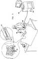
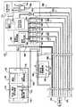
ここで、本発明の好ましい実施形態に従って構築され動作する内視鏡検査システムの、簡略化された絵図である図1を参照する。 Reference is now made to FIG. 1, which is a simplified pictorial illustration of an endoscopy system constructed and operative in accordance with a preferred embodiment of the present invention.
「内視鏡」および「内視鏡検査」という用語は、全体を通して、その慣例的な意味よりもいくぶん広く使用され、体腔、通路、ならびに、その他、たとえば小腸、大腸、動脈、および静脈などの内部で動作する装置および方法を指す。これらの用語は、通常目視検査を指すが、本明細書で使用されるように、それらは目視検査を使用する応用例に限定されず、目視検査に必ずしも関与しない装置、システム、および方法も指す。 The terms “endoscope” and “endoscopy” are used somewhat more extensively than their conventional meaning throughout and include body cavities, passages, and others such as the small intestine, large intestine, arteries, and veins. Refers to devices and methods that operate internally. These terms usually refer to visual inspection, but as used herein, they are not limited to applications that use visual inspection, but also refer to devices, systems, and methods that are not necessarily involved in visual inspection. .
図1から分かるように、すべてOlympus America Inc.社(2 Corporate Center Drive, Melville, NY 11747, USA)から市販される、CV160ビデオシステムセンタ、CLC−160光源、OEV−203ビデオモニタ、およびOFPフラッシングポンプを備える操作卓など、従来の内視鏡検査システム100が使用される。本発明の好ましい一実施形態に従って構築され動作する移動式内視鏡先端102が、患者の大腸内に配置されており、同じく本発明の好ましい一実施形態に従って構築され動作する多管腔チューブ104によって、システム100に結合される。多管腔チューブ104は、いずれも同様に本発明の好ましい一実施形態に従って構築され動作する、移動先端制御装置106および操作者制御装置108とインタフェースを取る。 As can be seen from FIG. 1, all of Olympus America Inc. (2 Corporate Center Drive, Melville, NY 11747, USA), such as a CV160 video system center, a CLC-160 light source, an OEV-203 video monitor, and a console equipped with an OFP flashing pump. An
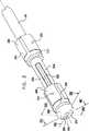
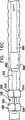
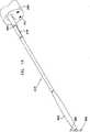
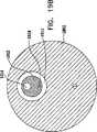
次に本発明の好ましい一実施形態に従って構築され動作する移動式内視鏡先端を示す、それぞれ概略分解図および組立図である図2および図3、ならびに、図3の線IVA−IVA、IVB−IVB、およびIVC−IVCに沿った概略断面図である、図4A、図4B、図4Cを参照する。 2 and 3, which are schematic exploded views and assembled views, respectively, showing a mobile endoscope tip constructed and operative in accordance with a preferred embodiment of the present invention, and lines IVA-IVA, IVB- in FIG. Reference is made to FIGS. 4A, 4B, and 4C, which are schematic cross-sectional views along IVB and IVC-IVC.
図2から図4Cから分かるように、とりわけ道具挿入、吹送、および吸引に有用な機器チャネルを画成する中央通路202と、通常10個である複数の周囲管腔204とを有する多管腔チューブ104は、ハウジング部分208内に形成された適当な構成の凹部206内に収まる。長手軸210について全体的に線対称のハウジング部分208は、凹部206を画成する比較的幅広の後部部分212、および比較的狭い主部分214を備える。 As can be seen from FIGS. 2-4C, a multi-lumen tube having a
後部部分212は、後部部分212の後部へと延びる、後部部分212の円周に沿って互いに120°離された軸方向スリットの3つの対220を備えて形成される。軸方向スリットの各対220の中間に膨張通路222が設けられ、それらはそれぞれ、多管腔チューブ202内に形成された対応する膨張通路224と連通し、この膨張通路224は、9つの多数周囲管腔204に含まれる3つの後部バルーン膨張管腔226のうちの1つとそれぞれ連通する。後部バルーン膨張管腔226は、膨張通路224の前方で封228によって封止される。 The
主部分214は、後部部分212の後部へと延びる、後部部分212の円周に沿って互いに離された3つの軸方向スロット230を備えて形成される。 The
摺動可能前方バルーン支持部238が、ハウジング部分208の主部分214上に摺動可能に取り付けられる。前方バルーン支持部238は、前方バルーン支持部238の後部へと延びる、前方バルーン支持部238の円周に沿って互いに120°離された軸方向スリットの3つの対240を備えて形成される。軸方向スリットの各対240の中間に膨張通路242が設けられ、それらはそれぞれ、対応する膨張通路244と連通し、この膨張通路244は、後方に、9つの多数周囲管腔204に含まれる3つの前方バルーン膨張管腔246のうちのそれぞれ1つとの摺動可能封止係合部内へと延びる。膨張通路244は、通常比較的剛性であり、多管腔チューブ104の前方端部で前方バルーン膨張管腔246内に挿入された適当に構成された低摩擦ライナ248内で、封止しながら摺動することが理解される。 A slidable
1対のピストンロッド250が、前方バルーン支持部238に固定されまたはそれと一体に形成され、その内側および後方へと延び、10個の多数周囲管腔204に含まれる前方バルーン支持部の2つの軸方向位置決め管腔252のうち一方に、それぞれ摺動可能に封止係合する。ピストンロッド250が、通常比較的剛性であり、多管腔チューブ104の前方端部で前方バルーン支持部の軸方向位置決め管腔252内に挿入された適当に構成された低摩擦ライナ254内で、封止しながら摺動することが理解される。 A pair of
比較的剛性の膨張通路244およびピストンロッド250は、好ましくは軸方向スロット230内に配置される。 The relatively
前部ハウジング部分260が、ハウジング部分208の主部214の前端262上に固定して取り付けられる。前部ハウジング部分は、摺動可能前方バルーン支持部238の中央ボア268を貫通して延びる円筒部分266に固定されまたはそれと一体に形成される、キャップ部分264を備える。円筒部分266の後端は、凹部270内に、かつ多管腔チューブ104の中央通路202内に画成されたショルダ272に押し付けられて収まる。円筒部分266の内部ボア274は、中央通路202によって画成される機器チャネルの連続部を画成する。 A
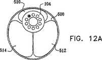
キャップ部分264の前端に、好ましくは発光ダイオード280および1つまたは複数の撮像センサ282が設けられる。キャップ部分264の前端から多管腔チューブ104内の周囲管腔286を通って移動先端制御装置106(図1)へと延びる、光ファイバおよび導電バンドル284を通して、発光ダイオード280に電流が供給され、素子282から撮像データが受け取られる。 A
ハウジング部分208内のスロット230を通して腸の内部と流体連通するための、さらなる周囲管腔290が、多管腔チューブ104内に設けられる。この管腔を通して、液体または加圧ガスを導入または排出することができる。 An additional
膨張可能バルーンシリンダ300が、ハウジング部分208の後部部分212上に取り付けられている。図2からはっきりと分かるように、膨張可能バルーンシリンダ300は均一な断面を有し、この断面は、その長手方向長さに沿って延びる、後部部分212の後部へと延びた対応する軸方向スリット220に係合する、軸方向壁の3つの対320を備える。軸方向壁の各対320は、円周壁部分322によって接合される。軸方向壁の対320は、膨張可能バルーンシリンダ300の円周に沿って互いに120°離されている。 An
軸方向壁の対320の中間に、3つの膨張可能バルーン部分324が画成され、それらはそれぞれ、別個の膨張通路222と別々に連通する。バルーン部分324は、接着剤によって、または、後部部分212の周囲の周りに分配される、3つの別々の個別制御可能に膨張可能かつ収縮可能なバルーン部分を画成するのに適したその他何らかのやり方で、その前端および後端ならびにスリット220にて、後部部分212に対して封止される。少なくとも3つの別々の個別制御可能に膨張可能かつ収縮可能なバルーン部分が好ましいが、より少ないまたはより多いいかなる適当な数のそのような別々の個別制御可能に膨張可能かつ収縮可能なバルーン部分を、代わりに使用することもできることが理解される。 In the middle of the pair of
膨張可能バルーンシリンダ350は、前方バルーン支持部238上に取り付けられる。図2ではっきりと分かるように、膨張可能バルーンシリンダ350は均一な断面を有し、この断面は、その長手方向長さに沿って延びる、前方バルーン支持部238の後部へと延びた対応する軸方向スリット240に係合する、軸方向壁の3つの対370を備える。軸方向壁の各対370は、円周壁部分372によって接合される。軸方向壁の対370は、膨張可能バルーンシリンダ350の円周に沿って、互いに120°離されている。 An
軸方向壁の対370の中間に、3つの膨張可能バルーン部分374が画成され、それらはそれぞれ、別個の膨張通路242と別々に連通する。バルーン部分374は、接着剤によって、または、前方バルーン支持部238の周囲の周りに分配される、3つの別々の個別制御可能に膨張可能かつ収縮可能なバルーン部分を画成するのに適したその他何らかのやり方で、その前端および後端ならびにスリット240にて、前方バルーン支持部238に対して封止される。後部部分212上のバルーン部分に対して位相が60°ずれた、少なくとも3つの別々の個別制御可能に膨張可能かつ収縮可能なバルーン部分が好ましいが、より少ないまたはより多いいかなる適当な数のそのような別々の個別制御可能に膨張可能かつ収縮可能なバルーン部分を、代わりに使用することもできることが理解される。 In the middle of the pair of
本発明の好ましい一実施形態によれば、バルーンシリンダ300および350は、全体的に伸縮性であり、膨張されないときのシリンダ300および350の半径の、約5〜20倍の半径までの拡張を許容するように収縮させることができることが理解される。好ましくは、10〜50ミリバールなどの比較的低圧で、バルーンシリンダ300および350の膨張が実現されることができる。 According to a preferred embodiment of the present invention,
変化する断面直径を有するほぼ管状の身体部分の生体内(in vivo)検査に有用な、本発明の好ましい一実施形態によれば、バルーンシリンダ300および350の拡張直径範囲は、ほぼ管状の身体部分の最大断面直径よりも大きく、したがって、拡張されたバルーンシリンダ300および350を、ほぼ管状の身体部分の内面に確実に係合させ、移動式内視鏡先端102をそこに係留することが理解される。好ましくは、バルーンシリンダ300および350は、比較的軟質の可撓性バルーンであり、ほぼ管状の身体部分に係合したときに、その内面形状と少なくとも部分的に共形になるように動作する。 In accordance with a preferred embodiment of the present invention, useful for in vivo inspection of generally tubular body parts having varying cross-sectional diameters, the expanded diameter range of
バルーンシリンダ300および350は、ラテックス、可撓性シリコーン、または高度に可撓性のナイロンなどの、よく知られた伸縮性材料とすることができることが理解される。あるいは、バルーンシリンダ300および350は、ラテックス、可撓性シリコーン、および高度に可撓性のナイロンなどに比べて可撓性および共形性が低い、ポリウレタン製とすることができる。好ましくは、バルーンシリンダ300および350は、ほぼ管状の身体部分のいかなる部分にも確実にきつく係留するのに十分な直径を有する。 It is understood that the
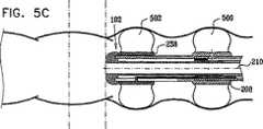
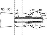
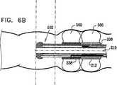
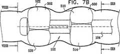
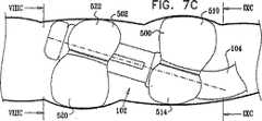
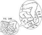
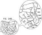
次に、腸内を通る前進運動の様々な段階における、図3の線IVB−IVBに沿った図2〜図4Cの移動式内視鏡先端の概略断面図である、図5A、図5B、図5C、図5D、図5E、図5F、および図5Gを参照する。図5A〜図5Gから分かるように、図2〜図4Cの移動式内視鏡先端102の移動運動は、ハウジング208に対する前方バルーン支持部238の相対的な軸方向変位と組み合わされた、ここでは参照番号500および502によって指示されそれぞれハウジング部分208および前方バルーン支持部238上に取り付けられたバルーンの、連続的な膨張および収縮の組合せによって達成される。バルーン500および502はそれぞれ、好ましくは、上記で説明したような複数の別々の個別制御可能に膨張可能かつ収縮可能なバルーン部分を備えることが理解される。 Next, FIGS. 5A, 5B, and 5B are schematic cross-sectional views of the mobile endoscope tip of FIGS. 2-4C, taken along line IVB-IVB of FIG. 3, at various stages of forward movement through the intestine. Reference is made to FIGS. 5C, 5D, 5E, 5F, and 5G. As can be seen from FIGS. 5A-5G, the moving motion of the
図5Aに移ると、バルーン500が膨張され、こうして腸の内壁に係合し、そこに対してハウジング部分208の位置を固定することが分かる。この向きでは、前方バルーン支持部238は、後部部分212に隣接する、後方の軸方向配置で示される。図5Bを見ると、ハウジング部分208が腸に対して軸方向に固定されたままで、前方バルーン支持部238が、ハウジング部分208に対して相対的に軸方向前方に動いたことが分かる。 Turning to FIG. 5A, it can be seen that the
図5Cに移ると、前方バルーン支持部238が図5Bでのその軸方向配置にある状態で、バルーン502が膨張され、腸の内壁に係合し、そこに対して前方バルーン支持部238の位置を固定することが分かる。その後、図5Dに示すように、バルーン500が収縮される。 Turning to FIG. 5C, with the
図5Eに移ると、バルーン500の収縮に続いて、前方バルーン支持部238が腸に対して軸方向に固定されたままで、前方バルーン支持部238が、ハウジング部分208に対して軸方向後方に動かされることが分かる。これによって、ハウジング208およびしたがって移動式内視鏡先端102が、軸方向前方へと移動する。 Turning to FIG. 5E, following deflation of the
図5Fに移ると、前方バルーン支持部238が図5Eでのその軸方向配置にある状態で、バルーン500が膨張され、腸の内壁に係合し、そこに対してハウジング部分208の位置を固定することが分かる。その後、図5Gに示すように、バルーン502が収縮される。 Turning to FIG. 5F, with the
したがって、このようにして移動式内視鏡先端102の前進変位が行われることが理解される。 Therefore, it is understood that the forward displacement of the
次に、腸内を通る後退運動の様々な段階における、図3の線IVB−IVBに沿った図2〜図4Cの移動式内視鏡先端の概略断面図である、図6A、図6B、図6C、図6D、図6E、図6F、および図6Gを参照する。図6A〜図6Gから分かるように、図2〜図4Cの移動式内視鏡先端102の後退移動運動は、ハウジング208に対する前方バルーン支持部238の相対的な軸方向変位と組み合わされた、ここでもまたそれぞれ参照番号500および502によって指示されハウジング部分208および前方バルーン支持部238上に取り付けられたバルーンの、連続的な膨張および収縮の組合せによって達成される。バルーン500および502はそれぞれ、好ましくは、上記で説明したような複数の別々の個別制御可能に膨張可能かつ収縮可能なバルーン部分を備えることが理解される。 Next, FIGS. 6A, 6B, and 6B are schematic cross-sectional views of the mobile endoscope tip of FIGS. 2-4C, taken along line IVB-IVB of FIG. 3, at various stages of retraction movement through the intestine. Reference is made to FIGS. 6C, 6D, 6E, 6F, and 6G. As can be seen from FIGS. 6A-6G, the retracting movement of the
図6Aに移ると、バルーン500が膨張されて、腸の内壁に係合し、そこに対してハウジング部分208の位置を固定することが分かる。この配置では、前方バルーン支持部238は、後部部分212に隣接する後方軸方向配置で示される。図6Bを見ると、前方バルーン支持部238が図6A内のその軸方向配置にある状態で、バルーン502が膨張されて腸の内壁に係合し、そこに対して前方バルーン支持部238の位置を固定することが分かる。その後、図6Cに示すように、バルーン500が収縮される。 Turning to FIG. 6A, it can be seen that the
図6Dに移ると、前方バルーン支持部238が腸に対して軸方向に固定されたままで、前方バルーン支持部238が、ハウジング部分208に対して軸方向前方に動かされることが分かる。 Turning to FIG. 6D, it can be seen that the
図6Eに移ると、前方バルーン支持部238が図6Dでのその軸方向配置にある状態で、バルーン500が膨張されて、腸の内壁に係合し、そこに対してハウジング部分208の位置を固定することが分かる。その後、図6Fに示すように、バルーン502が収縮される。 Turning to FIG. 6E, with the
図6Gに移ると、ハウジング部分208が腸に対して軸方向に固定されたままで、前方バルーン支持部238が、ハウジング部分208に対して軸方向後方に移動したことが分かる。 Turning to FIG. 6G, it can be seen that the
したがって、このようにして移動式内視鏡先端102の後退移動が行われることが理解される。あるいは、バルーン500および502は両方とも、収縮されることができ、移動式内視鏡先端102は、多管腔チューブ104の引張りによって腸外に引き出されることができる。 Therefore, it is understood that the
次に、バルーン500および502の個々のバルーンローブを適切に選択可能に膨張させることによって実現されることが可能になる、図2〜図4Cの移動式内視鏡先端102の様々な異なる向きを示す、図7A〜図9Cを参照する。これらの図は、バルーン500および502のバルーンローブの回転向きの位相の差を考慮した、バルーン500のバルーンローブの何らかの適当な非同一な膨張、ならびに、反対の方向で対応するバルーン502の非同一な膨張によって実現される、平行でなく傾斜した向きの例である。 Next, various different orientations of the
図7A、図8A、および図9Aに移ると、身体通路の内にある、図1〜図6Gの移動式内視鏡先端の、第1の、下方に面した選択可能な傾斜向きの図が見られる。この向きは、ここでは参照番号520によって指示される、バルーン502の1つのバルーンローブの比較的小さい膨張、ならびに参照番号522および524によって指示される、バルーン502のバルーンローブの比較的大きい膨張がもたらされると同時に、ここでは参照番号510で指示される、バルーン500の1つのバルーンローブの比較的小さい膨張、ならびに参照番号512および514によって指示される、バルーン500のバルーンローブの比較的大きい膨張によって実現される。図7A〜図7Cの向きでは、バルーンローブ510および520は、それぞれ図7A〜図7Cの方向で移動式内視鏡先端102の頂部および底部にあることに留意されたい。 Turning to FIGS. 7A, 8A, and 9A, a first, downwardly-facing, selectable tilted view of the mobile endoscope tip of FIGS. 1-6G within the body passageway. It can be seen. This orientation results in a relatively small inflation of one balloon lobe of
図7B、図8B、および図9Bに移ると、身体通路内にある図1〜図6Gの移動式内視鏡先端の、第2の平行向きの図が見られる。この向きは、バルーン500のバルーンローブ510、512、および514のほぼ同一の膨張、ならびに、バルーン502のバルーンローブ520、522、および524の同一の膨張によって実現される。 Turning to FIGS. 7B, 8B, and 9B, a second parallel view of the mobile endoscope tip of FIGS. 1-6G in the body passageway can be seen. This orientation is achieved by approximately the same inflation of the
図7C、図8C、および図9Cに移ると、身体通路内にある図1〜図6Gの移動式内視鏡先端の、第3の、上方に面し選択可能に傾斜した向きの図が見られる。この向きは、バルーン502のバルーンローブ520の比較的大きい膨張、ならびにバルーン502のバルーンローブ522および524の比較的小さい膨張がもたらされることによるのと同時に、バルーン500のバルーンローブ510の比較的大きい膨張、ならびにバルーン500のバルーンローブ512および514の比較的小さい膨張によって実現される。 Turning to FIGS. 7C, 8C, and 9C, a third, upwardly facing, selectively tilted view of the tip of the mobile endoscope of FIGS. 1-6G in the body passageway is seen. It is done. This orientation is due to the relatively large expansion of the
次に、身体通路内にある図1〜図6Gの移動式内視鏡先端の、選択可能に平行な中心からずれた向きを示す側面図である図10Aおよび図10B、図10Aおよび図10Bに対応し、後方を見た、それぞれ図10Aおよび図10Bの平面XIA−XIA、XIB−XIBに沿った図である図11Aおよび図11B、ならびに、図10Aおよび図10Bに対応し、前方を見た、それぞれ図10Aおよび図10Bの平面XIIA−XIIA、XIIB−XIIBに沿った図である図12Aおよび図12Bを参照する。これらの図は、バルーン500および502のバルーンローブの回転向きにおける位相の差を考慮した、バルーン500のバルーンローブ510、512、および514の何らかの適切な非同一の膨張、ならびに、バルーン502のバルーンローブ520、522、および524の対応する非同一の膨張によって達成される、平行向きの例である。 Next, FIGS. 10A and 10B, 10A and 10B are side views showing the orientation of the movable endoscope tip in FIGS. Corresponding and looking backwards, corresponding to FIGS. 11A and 11B and FIGS. 10A and 10B, which are views along the planes XIA-XIA, XIB-XIB of FIGS. 10A and 10B, respectively, looking forward Reference is made to FIGS. 12A and 12B, which are views along planes XIIA-XIIA, XIIB-XIIB of FIGS. 10A and 10B, respectively. These figures illustrate any suitable non-identical inflation of
図10A、図11A、および図12Aに移ると、身体通路内にある図1〜図6Gの移動式内視鏡先端の、第1の中心からずれた平行向きの図が見られる。この向きは、バルーン500および502のバルーンローブの回転向きの位相の差を考慮した、バルーン500の、バルーンローブ510の比較的小さい膨張とバルーンローブ512および514の比較的大きい膨張、ならびにバルーン502の、バルーンローブ502の対応する比較的大きい膨張とバルーンローブ522および524の比較的小さい膨張によって達成される。 Turning to FIGS. 10A, 11A, and 12A, a parallel view of the distal end of the mobile endoscope of FIGS. 1-6G in the body passage, offset from the first center, can be seen. This orientation takes into account the phase difference between the rotational orientations of the balloon lobes of the
図10B、図11B、および図12Bに移ると、身体通路内にある図1〜図6Gの移動式内視鏡先端の、第2の中心からずれた平行向きの図が見られる。この向きは、バルーン500の、バルーンローブ510の比較的大きい膨張とバルーンローブ512および514の比較的小さい膨張、ならびにバルーン502の、バルーンローブ520の対応する比較的小さい膨張とバルーンローブ522および524の比較的大きい膨張によって達成される。 Turning to FIGS. 10B, 11B, and 12B, a parallel view of the distal end of the mobile endoscope of FIGS. 1-6G in the body passage, offset from the second center, can be seen. This orientation is such that the
図7A〜図12Bを考慮することによって、バルーン500および502の両方の上に少なくとも3つのバルーンローブが設けられる場合、実際には、移動式内視鏡先端102の、いかなる所望の幾何学的に許可された向きも実現されることができることが理解されることができる。これはたとえば、上下および左右の傾斜ならびにそれらの組合せ、ならびに、所望の上下および左右に中心からずれた平行向きならびにそれらの組合せを含む。 By considering FIGS. 7A-12B, if at least three balloon lobes are provided on both
バルーン500および502それぞれの上に少なくとも2つのバルーンローブが設けられ、特にバルーン500および502の少なくとも2つのバルーンローブが方位角的にずれる場合、移動式内視鏡先端102の、様々な所望の幾何学的に許可された向きが実現されることができることが理解される。 At least two balloon lobes are provided on each of the
移動式内視鏡が押し込み機構以外によって動かされることにより、多管腔チューブ104の可撓性をその他の内視鏡チューブよりもかなり高くすることができることは、本発明の特有の特徴である。 It is a unique feature of the present invention that the flexibility of the
次に、多管腔チューブ104の中央通路202内、および移動式内視鏡先端102の円筒部分266の内部ボア274内に画成された機器チャネルを通って移動するようになされた、付属装置600の概略的な絵図である図13を参照する。付属装置600は、それらのいくつかは当技術分野でよく知られた、生検鉗子、ポリープ切除わな、異物回収装置、ヒートプローブおよび針など、いかなる適当な付属装置の中から選択されることもできる。本発明の好ましい実施形態によれば、ピストン602が、付属装置に、その本体604に沿ってその先端606の上流で結合される。ピストン602は、たとえば、従来の内視鏡検査システムに設けられた従来の吹送および吸引機能によって行われることができる、機器チャネルの適当な正または負の与圧によってもたらされるようなその上流と下流の圧力差に応答して、機器チャネルに沿って摺動可能に封止されて動くように構成される。 Next, an accessory device adapted to move through an instrument channel defined in the
次に、本発明の好ましい一実施形態に従って構築され動作する図1〜図13の内視鏡検査システムの部分を示す、簡略化された、部分的にブロック図、部分的に概略図である図14を参照する。 FIG. 2 is a simplified, partially block diagram, partially schematic diagram illustrating portions of the endoscopy system of FIGS. 1-13 constructed and operating in accordance with a preferred embodiment of the present invention. 14 is referred to.
図14から分かるように、すべてOlympus America Inc.社(2 Corporate Center Drive, Melville, NY 11747, USA)から市販される、CV−160ビデオシステムセンタ、CLC−160光源、OEV−203ビデオモニタ、およびOFPフラッシングポンプを備える操作卓などの、従来の内視鏡検査システム100が使用される。従来の内視鏡検査システム100は、吹送/吸引発生装置700、および液体供給源702を備え、これらは流量制御弁704を通じて、多管腔チューブ104の中央通路202によって、かつ移動式内視鏡先端102の円筒部分266の内部ボア274によって画成された、機器チャネルと連通する。従来の内視鏡検査システム100はまた、好ましくは、撮像システム710およびLED制御装置712を備え、これらは、好ましくは、多管腔チューブ104内の管腔286を通って延びる光ファイバおよび導電バンドル284として実施される、電子データおよび電力ラインによって接続される。 As can be seen from FIG. 14, all of Olympus America Inc. (2 Corporate Center Drive, Melville, NY 11747, USA), such as consoles equipped with CV-160 video system center, CLC-160 light source, OEV-203 video monitor, and OFP flashing pump. An
好ましくはジョイスティック722、傾斜/非傾斜機能選択スイッチ724、ならびに動きの方向(前方/後方)および速さを調節するためのボタン725を備える、操作者制御装置108が、移動先端制御装置106の動作を調節する。本発明の好ましい一実施形態では、図示のとおり、操作者制御装置108は、空気圧発生装置728、真空発生装置730、および正および負の油圧供給源732を操作する、移動先端制御回路726への制御入力を提供する。 The
空気圧発生装置728および真空発生装置730は、バルーンローブ510、512、514、520、522および524を選択可能に膨張させるために、適当なマニホルド734および736を通じて、かつ、各管腔用の参照番号740、742、744、746、748および750によって指示される個々のフローバルブを介して、管腔226および246に結合される。正および負の油圧供給源732は、ピストンロッド250を駆動するために、フローバルブ752を介して管腔252に結合される。さらに、フローバルブ754は、処理流体リザーバ756からの、管腔290への処理流体供給を調節する。さらなる流体弁758が、腸から真空状態に維持された廃棄流体位置(図示せず)への、管腔290を通した処理流体の除去を調節する。
フローバルブ704、740、742、744、746、748、750、752、754および758は、腸内の移動式内視鏡先端102の選択された配置および/または傾斜を提供するために、バルーンローブ510、512、514、520、522および524を適当に膨張および収縮させるように、かつ、移動式内視鏡先端102の移動運動のために、また図15を参照しながら以下で説明するように処理流体を腸へと選択可能に供給するために、前方バルーン支持部238を適当に変位させるように、移動先端制御回路726を介して、操作者制御装置108によって制御される。
次に、腸流体処理動作モードである図1〜図12Bの移動式内視鏡先端の、簡略化された絵図である図15を参照する。図15から分かるように、バルーン500のバルーンローブ510、512、および514、ならびにバルーン502のバルーンローブ520、522、および524などの管状身体部分の封止要素は、バルーンローブ510、512、および514と、バルーンローブ520、522、および524との中間の腸の空間を腸の残りの空間から封止するために、好ましくはすべて膨張される。 Reference is now made to FIG. 15, which is a simplified pictorial illustration of the distal tip of the mobile endoscope of FIGS. As can be seen from FIG. 15, the sealing elements of the tubular body parts, such as
封止が達成されると、処理流体760が、処理流体リザーバ756から、弁754、管腔290、およびスロット230を通じて腸の封止部分へと供給される。処理に続いて、処理流体760は腸の封止部分から、スロット230、管腔290、および弁758を通じて流体廃棄位置(図示せず)へと吸引されることができる。任意でかつ好ましくは、処理流体760は、治療流体、造影強化流体、消毒流体、酸性溶液、塩基性溶液、またはその他いかなる適当な流体のうちの少なくとも1つを含む。 Once the seal is achieved, processing
次に、ガイドワイヤ動作モードである図1〜図12Bの移動式内視鏡先端の、簡略化された絵図である図16A〜図16Cを参照する。図16Aから分かるように、バルーン500のバルーンローブ510、512、および514、ならびにバルーン502のバルーンローブ520、522、および524は、移動式内視鏡先端102を腸に係留するために、好ましくはすべて膨張される。所望の位置で係留が達成されると、図16Bから分かるように多管腔チューブ104に張力がかけられる。 Reference is now made to FIGS. 16A-16C, which are simplified pictorial views of the distal tip of the mobile endoscope of FIGS. As can be seen from FIG. 16A,
バルーン500および502のそれぞれの直径は、腸のいかなる部分に確実にきつく係留するのにも十分な大きさであることが理解される。 It will be appreciated that the diameter of each of the
図16Cから分かるように、オーバーチューブ800が、多管腔チューブ104を覆って、それをガイドワイヤとして利用して摺動させられる。オーバーチューブ800は、好ましくは、その前方部分802にて、内視鏡検査道具804を備える。好ましくは、内視鏡検査道具804は、治療、診察、または手術道具とすることができ、多管腔チューブ104に沿って選択可能に位置決めすることができる。本発明の好ましい一実施形態では、内視鏡検査道具804は、超音波振動子である。本発明の別の好ましい実施形態では、内視鏡検査道具804は、X線放射源/発生装置である。 As can be seen from FIG. 16C, an overtube 800 is slid over the
次に、それぞれ本発明の別の好ましい実施形態に従って構築され動作する、内視鏡検査システムの簡略化された絵図、ならびにそれぞれ本発明の好ましい一実施形態に従って構築され動作する、付属装置の簡略化された絵図および断面図である、図17〜図19Bを参照する。 Next, a simplified pictorial view of an endoscopy system, each constructed and operative in accordance with another preferred embodiment of the present invention, as well as a simplification of an accessory device each constructed and operative in accordance with a preferred embodiment of the present invention. Reference is made to FIGS. 17-19B which are pictorial and sectional views.
図17〜図19Bから分かるように、すべてOlympus America Inc.社(2 Corporate Center Drive, Melville, NY 11747, USA)から市販される、CV160ビデオシステムセンタ、CLC−160光源、OEV−203ビデオモニタ、およびOFPフラッシングポンプを備える操作卓など、従来の内視鏡検査システム1000が使用される。Olympus America Inc.社(2 Corporate Center Drive, Melville, NY 11747, USA)から市販される、CF−Q160ALビデオ結腸鏡などの、従来の内視鏡検査システム1000の一部を形成する従来の内視鏡1002が使用されることができる。 As can be seen from FIGS. 17-19B, all of Olympus America Inc. (2 Corporate Center Drive, Melville, NY 11747, USA), such as a CV160 video system center, a CLC-160 light source, an OEV-203 video monitor, and a console equipped with an OFP flashing pump. An
本発明の好ましい一実施形態に従って構築され動作する内視鏡道具1010は、従来の内視鏡1002の機器チャネル1011を通って延びる。内視鏡道具1010は、膨張開口1017を通じてバルーン1016を膨張および収縮させるための第1の管腔1014、および第2の管腔1018を少なくとも備える、多管腔チューブ1012を備えることを特徴とする。好ましくは、第2の管腔1018は、緊張および圧縮ワイヤ1020を収容することができる。あるいは、またはさらに、第2の管腔1018は、他の機能を有することができる。さらなる代替形態として、内視鏡道具1010の一部を形成する多管腔チューブ1012は、3つ以上の管腔を備えることができる。好ましくは、多管腔チューブ1012の断面領域は、そこを通る吹送用流体の供給および流体の排出を可能にするために、機器チャネル1011のそれよりも十分に小さい。 An
本発明の好ましい一実施形態によれば、内視鏡道具1010および多管腔チューブ1012は、一般に、従来の内視鏡1002およびその内視鏡チューブより可撓性がかなり高いことが理解される。 In accordance with a preferred embodiment of the present invention, it will be appreciated that
本発明の好ましい一実施形態によれば、バルーン1016は、一般的に伸縮性であり、それが膨張されていないときの直径に比べて、約5〜20倍の直径に大きく伸張させることができることが理解される。小腸内視鏡検査に有用な特定の一実施形態では、完全に伸張されたときのバルーン直径は4cmである。好ましくは、直径4cm未満までのバルーン1016の膨張は、10〜50ミリバールの範囲など比較的低圧で達成されることができる。大腸内視鏡検査に有用な別の特定の実施形態では、完全に膨張されたときのバルーン直径は7cmである。好ましくは、直径7cm未満までのバルーン1016の膨張は、10〜50ミリバールの範囲など比較的低圧で達成されることができる。 According to one preferred embodiment of the present invention, the
様々な断面直径を有するほぼ管状の身体部分のin vivo検査に有用な、本発明の好ましい一実施形態によれば、バルーン1016の拡大直径範囲は、ほぼ管状の身体部分の最大断面直径よりも大きく、したがって、拡張されたバルーン1016をほぼ管状の身体部分の内面に確実に係合させ、そこに内視鏡道具1010を係留することが理解される。好ましくは、バルーン1016は、ほぼ管状の身体部分に係合したときに、その内面形状と少なくとも部分に共形となるように動作する、比較的軟質で高度に弾性のバルーンである。 In accordance with a preferred embodiment of the present invention, useful for in vivo examination of generally tubular body parts having various cross-sectional diameters, the expanded diameter range of
バルーン1016は、ラテックス、可撓性シリコーン、または高度に可撓性のナイロンなど、よく知られた伸縮性材料製とすることができることが理解される。あるいは、バルーン1016は、ラテックス、可撓性シリコーン、および高度に可撓性のナイロンなどに比べて可撓性および共形性が低い、ポリウレタン製とすることができる。好ましくは、バルーン1016の直径は、ほぼ管状の身体部分のいかなる部分にも確実にきつく係留するのに十分な大きさである。 It is understood that the
図17〜図19Bから分かるように、内視鏡道具1010は、好ましくは、道具位置決め制御装置1024、およびバルーン膨張/収縮制御インタフェース1026を備える。多管腔チューブ1012および内視鏡道具1010全体は、従来の内視鏡1002の一部を形成する従来の操作者制御装置1032上の、従来の道具ポート1030を通して挿入され、取り出されることができることが理解される。 As can be seen from FIGS. 17-19B, the
次に、図17〜図19Bの様々な動作向きの内視鏡道具1010を示す略図である、図20A、図20B、図20C、図20D、図20E、図20F、図20G、図20Hおよび図20Iを参照する。図示の実施形態では、ワイヤ1020の適当な緊張および内視鏡道具1010の腸に対する適当な回転向きと組み合わされた、内視鏡1002の機器チャネル1011を通る道具の適当な軸方向変位によって、内視鏡道具1010前端の所望の方向向きが得られる。 Next, FIG. 20A, FIG. 20B, FIG. 20C, FIG. 20D, FIG. 20E, FIG. 20F, FIG. 20G, FIG. Reference is made to 20I. In the illustrated embodiment, an appropriate axial displacement of the tool through the
図20Aから分かるように、内視鏡道具1010は、収縮状態の間、主に内視鏡1002の機器チャネル1011内に配置され、また、そこから突出するバルーン1016を有する。 As can be seen from FIG. 20A, the
図20Bは、機器チャネル1011からさらに延びる内視鏡道具1010を示し、図20Cは、矢印1022によって指示されるような多管腔チューブ1012の適当なねじりによってその図20Bの向きに対して180°回転された、内視鏡道具1010を示す。 FIG. 20B shows an
図20Dは、道具が従来のやり方で前方に押されてその図20C内の向きにあるときに、ワイヤ1020の緊張によって生じる、内視鏡道具1010の前端の曲げを示す。 FIG. 20D shows the bending of the front end of the
図20Eは、ワイヤ1020にかかる張力を道具位置決め制御装置1024の動作によって解放することと組み合わせて、道具を前方に押すことによって生じる、腸を通る内視鏡道具1010のさらなる前進を示す。 FIG. 20E shows further advancement of the
図20Fは、バルーン膨張/収縮制御インタフェース1026の動作による、バルーン1016の膨張を示す。本発明の好ましい一実施形態によれば、この膨張は、内視鏡道具1010の前端をバルーン1016の位置で腸に係留する。 FIG. 20F illustrates the inflation of the
図20Gは、多管腔チューブ1012の引張りによる、多管腔チューブ1012を備える内視鏡道具1010の緊張を示す。 FIG. 20G shows the tension of the
図20Hは、多管腔チューブを一種のガイドワイヤとして使用して、多管腔チューブ1012に沿って前方に押された内視鏡1002を示す。内視鏡1002は、従来のやり方で前方に押されることができる。その後、図19Iに示すように、バルーン1016は収縮されることができる。 FIG. 20H shows the
図20Aに示す向きと同様の、好ましくは機器チャネル1011の前端がバルーン1016の直後にくる位置までの、腸を通る内視鏡のさらなる前進は、図20A〜図20Iを参照して上記で説明したいくつかまたはすべてのステップを、遭遇されるジオメトリによって要求されるように繰り返すことによって達成されることができる。 Further advancement of the endoscope through the intestine, similar to the orientation shown in FIG. 20A, preferably to a position where the front end of
次に、それぞれ本発明の別の好ましい実施形態に従って構築され動作する内視鏡検査システムの簡略化された絵図、およびそれぞれ本発明の好ましい一実施形態に従って構成され動作する付属装置の簡略化された断面図である、図21〜図23Bを参照する。 Next, a simplified pictorial illustration of an endoscopy system each constructed and operating in accordance with another preferred embodiment of the present invention, and a simplified accessory device each constructed and operated in accordance with a preferred embodiment of the present invention. Reference is made to FIGS. 21-23B, which are cross-sectional views.
図21〜図23Bから分かるように、すべてOlympus America Inc.社(2 Corporate Center Drive, Melville, NY 11747, USA)から市販される、CV160ビデオシステムセンタ、CLC−160光源、OEV−203ビデオモニタ、およびOFPフラッシングポンプを備える操作卓など、従来の内視鏡検査システム1300が使用される。Olympus America Inc.社(2 Corporate Center Drive, Melville, NY 11747, USA)から市販される、CF−Q160ALビデオ結腸鏡などの、従来の内視鏡検査システム1300の一部を形成する従来の内視鏡1302が使用されることができる。本発明の好ましい実施形態によれば、周囲バルーン1304は、図示のとおり内視鏡1302上に取り付けられることができる。好ましくは、バルーン1304の膨張および収縮は、その内部と連通するチューブ1306によって行われることができる。 As can be seen from FIGS. 21 to 23B, all of Olympus America Inc. (2 Corporate Center Drive, Melville, NY 11747, USA), such as a CV160 video system center, a CLC-160 light source, an OEV-203 video monitor, and a console equipped with an OFP flashing pump. An
本発明の好ましい一実施形態に従って構築され動作する内視鏡道具1310は、従来の内視鏡1302の機器チャネル1311を通って延びる。内視鏡道具1310は、膨張開口1317を通じてバルーン1316を膨張および収縮させるための第1の管腔、および第2の管腔1318を少なくとも備える、多管腔チューブ1312を備えることを特徴とする。好ましくは、第2の管腔1318は、緊張および圧縮ワイヤ1320を収容することができる。あるいは、またはさらに、第2の管腔1318は、他の機能を有することができる。さらなる代替形態として、内視鏡道具1310の一部を形成する多管腔チューブ1312は、3つ以上の管腔を備えることができる。好ましくは、多管腔チューブ1312の断面領域は、そこを通る吹送用流体の供給および流体の排出を可能にするために、機器チャネル1311のそれよりも十分に小さい。 An
本発明の好ましい一実施形態によれば、内視鏡道具1310および多管腔チューブ1312は、一般に、従来の内視鏡1302およびその内視鏡チューブより可撓性がかなり高いことが理解される。 In accordance with a preferred embodiment of the present invention, it will be appreciated that
本発明の好ましい一実施形態によれば、バルーン1316は、一般的に伸縮性であり、それが膨張されていないときの直径に比べて、約5〜20倍の直径に大きく伸張させることができることが理解される。小腸内視鏡検査に有用な特定の一実施形態では、完全に伸張されたときのバルーン直径は4cmである。好ましくは、直径4cm未満までのバルーン1316の膨張は、10〜50ミリバールの範囲など比較的低圧で達成されることができる。大腸内視鏡検査に有用な別の特定の実施形態では、完全に膨張されたときのバルーン直径は7cmである。好ましくは、直径7cm未満までのバルーン1316の膨張は、10〜50ミリバールの範囲など比較的低圧で達成されることができる。 According to one preferred embodiment of the present invention, the
様々な断面直径を有するほぼ管状の身体部分のin vivo検査に有用な、本発明の好ましい一実施形態によれば、バルーン1316の拡大直径範囲は、ほぼ管状の身体部分の最大断面直径よりも大きく、したがって、拡張されたバルーン1316をほぼ管状の身体部分の内面に確実に係合させ、そこに内視鏡道具1310を係留することが理解される。好ましくは、バルーン1316は、ほぼ管状の身体部分に係合したときに、その内面形状と少なくとも部分に共形となるように動作する、比較的軟質で高度に弾性のバルーンである。 According to a preferred embodiment of the present invention, useful for in vivo examination of generally tubular body parts having various cross-sectional diameters, the expanded diameter range of
バルーン1316は、ラテックス、可撓性シリコーン、または高度に可撓性のナイロンなど、よく知られた伸縮性材料製とすることができることが理解される。あるいは、バルーン1316は、ラテックス、可撓性シリコーン、および高度に可撓性のナイロンなどに比べて可撓性および共形性が低い、ポリウレタン製とすることができる。好ましくは、バルーン1316の直径は、ほぼ管状の身体部分のいかなる部分にも確実にきつく係留するのに十分な大きさである。 It is understood that the
図21〜図23Bから分かるように、内視鏡道具1310は、好ましくは、道具位置決め制御装置1324、およびバルーン膨張/収縮制御インタフェース1326を備える。さらに、チューブ1306と連通し、周囲バルーン1304の膨張および収縮を調節する、周囲バルーン膨張/収縮制御インタフェース1328が、好ましくは設けられる。多管腔チューブ1312および内視鏡道具1310全体は、従来の内視鏡1302の一部を形成する従来の操作者制御装置1332上の、従来の道具ポート1330を通して挿入され、取り出されることができることが理解される。 As can be seen from FIGS. 21-23B, the
次に、様々な動作向きの図21〜図23Bの内視鏡道具1310を示す略図である、図24A、図24B、図24C、図24D、図24E、図24F、図24G、図24H、図24I、図24J、図24K、および図24Lを参照する。図示の実施形態では、ワイヤ1320の適当な緊張および内視鏡道具1310の腸に対する適当な回転向きと組み合わされた、内視鏡1302の機器チャネル1311を通る道具の適当な軸方向変位によって、内視鏡道具1310前端の所望の方向向きが得られる。 Next, FIGS. 24A, 24B, 24C, 24D, 24E, 24F, 24G, 24H, and 24H are schematic diagrams illustrating the
図24Aから分かるように、内視鏡道具1310は、収縮状態の間、主に内視鏡1302の機器チャネル1311内に配置され、また、そこから突出するバルーン1316を有する。図示のとおり、周囲バルーン1304は、収縮状態である。 As can be seen in FIG. 24A, the
図24Bは、収縮状態の間、主に内視鏡1302の機器チャネル1311内に配置され、また、そこから突出するバルーン1316を有する、内視鏡道具1310を示す。図示のとおり、周囲バルーン1304は、腸の内壁と係合する膨張状態であり、それによって、内視鏡1302をそこに係留する。 FIG. 24B shows an
図24Cは、さらに機器チャネル1311から延びる内視鏡道具1310を示し、図24Dは、矢印1340によって指示されるような多管腔チューブ1312の適当なねじりによってその図24Cの向きに対して180°回転された、内視鏡道具1310を示す。 FIG. 24C further shows an
図24Eは、道具が従来のやり方で前方に押されてその図24内の向きにあるときに、ワイヤ1320の緊張によって生じる、内視鏡道具1310の前端の曲げを示す。 FIG. 24E shows the bending of the front end of the
図24Fは、ワイヤ1320にかかる張力を道具位置決め制御装置1324の動作によって解放することと組み合わせて、道具を前方に押すことによって生じる、腸を通る内視鏡道具1310のさらなる前進を示す。 FIG. 24F shows further advancement of the
図24Gは、バルーン膨張/収縮制御インタフェース1326の動作による、バルーン1316の膨張を示す。本発明の好ましい一実施形態によれば、この膨張は、内視鏡道具1310の前端をバルーン1316の位置で腸に係留する。 FIG. 24G illustrates inflation of the
図24Hは、多管腔チューブ1312の引張りによる、多管腔チューブ1312を備える内視鏡道具1310の緊張を示す。 FIG. 24H shows the tension of the
図24Iは、周囲バルーン1304の収縮を示す。 FIG. 24I shows the deflation of the surrounding
図24Jは、多管腔チューブを一種のガイドワイヤとして使用して、多管腔チューブ1312に沿って前方に押された内視鏡1302を示す。内視鏡1302は、従来のやり方で前方に押されることができる。 FIG. 24J shows the
図24Kは、腸の内壁と係合し、それによって内視鏡1302をそこに係留する、周囲バルーン1304の膨張を示す。 FIG. 24K shows the inflation of the surrounding
その後、図24Lに示すように、バルーン1316が収縮されることができる。 Thereafter, as shown in FIG. 24L, the
図24Bに示す向きと同様の、好ましくは機器チャネル1311の前端がバルーン1316の直後にくる位置までの、腸を通る内視鏡のさらなる前進は、図24B〜図24Lを参照して上記で説明したいくつかまたはすべてのステップを、遭遇されるジオメトリによって要求されるように繰り返すことによって達成されることができる。 Further advancement of the endoscope through the intestine, similar to the orientation shown in FIG. 24B, preferably to a position where the front end of the
本発明は、上記で特に図示および説明されてきたものに限定されないことが、当業者には理解されるであろう。本発明の範囲はむしろ、上記の明細書を読めば当業者が考え付く、従来技術にはない、上記で説明された様々な特徴の組合せおよび部分の両方、ならびにその修正形態を包含する。 It will be appreciated by persons skilled in the art that the present invention is not limited to what has been particularly shown and described hereinabove. Rather, the scope of the present invention encompasses both the various feature combinations and portions described above, as well as modifications thereof, not found in the prior art, as would occur to one skilled in the art upon reading the above specification.
図7Bは、身体通路内にある、図1〜図6Gの移動式内視鏡先端の選択可能な傾斜向きを示す側面図である。 FIG. 7B is a side view showing selectable tilt orientations of the mobile endoscope tip of FIGS. 1-6G in the body passageway.
図7Cは、身体通路内にある、図1〜図6Gの移動式内視鏡先端の選択可能な傾斜向きを示す側面図である。
図8Bは、図7Bに対応する、図7Bの面VIIIB−VIIIBに沿った、後方に向かって見た略図である。 FIG. 8B is a schematic view looking rearward, along plane VIIIB-VIIIB of FIG. 7B, corresponding to FIG. 7B.
図8Cは、図7Cに対応する、図7Cの面VIIIC−VIIICに沿った、後方に向かって見た略図である。
図9Bは、図7Bに対応する、図7Bの面IXB−IXBに沿った、前方に向かって見た略図である。 FIG. 9B is a schematic view looking forward along the plane IXB-IXB of FIG. 7B, corresponding to FIG. 7B.
図9Cは、図7Cに対応する、図7Cの面IXC−IXCに沿った、前方に向かって見た略図である。
図10Bは、身体通路内にある図1〜図6Gの移動式内視鏡先端の、選択可能な平行向きを示す側面図である。
図11Bは、図10Bに対応する、図10Bの面XIB−XIBに沿った、後方に向かって見た略図である。
図12Bは、図10Bに対応する、図10Bの面XIIB−XIIBに沿った、前方に向かって見た略図である。
図16Bは、ガイドワイヤ動作モードである、図1〜図12Bの移動式内視鏡先端を示す簡略化された絵図である。 FIG. 16B is a simplified pictorial diagram showing the distal tip of the mobile endoscope of FIGS. 1-12B in the guidewire mode of operation.
図16Cは、ガイドワイヤ動作モードである、図1〜図12Bの移動式内視鏡先端を示す簡略化された絵図である。
図19Bは、本発明の好ましい一実施形態に従って構築され動作する付属装置を示す断面図である。
図23Bは、本発明の好ましい一実施形態に従って構築され動作する付属装置を示す断面図である。
Claims (16)
Translated fromJapanese内視鏡先端であって、長手軸に沿って延び、前記長手軸に沿う少なくとも一つの第1の軸方向位置にて前記内視鏡先端に結合された複数の第1の選択的に径方向に拡張可能な要素と、前記長手軸に沿う少なくとも一つの第2の軸方向位置にて前記内視鏡先端に結合された複数の第2の選択的に径方向に拡張可能な要素とを有する、前記内視鏡先端と、
前記内視鏡先端を選択可能に位置決めするために、前記第1および第2の選択的に径方向に拡張可能な複数の要素の選択的な拡張を制御する内視鏡先端制御装置と、
を備え、
前記第1の複数の選択的に径方向に拡張可能な要素が少なくとも2つの個別に径方向に拡張可能な要素を備え、
前記第2の複数の選択的に径方向に拡張可能な要素が、少なくとも2つの個別に選択的に径方向に拡張可能な要素を備え、
前記第2の複数の選択的に径方向に拡張可能な要素に設けられた前記少なくとも2つの個別に選択的に径方向に拡張可能な要素が、前記第1の複数の選択的に径方向に拡張可能な要素に設けられた前記少なくとも2つの個別に選択的に径方向に拡張可能な要素に対して、前記内視鏡先端の長手軸の周りに角度を付けてずれて配置されている、内視鏡アセンブリ。In the endoscope assembly,
An endoscope tip, a plurality of first selectively radial directions extending along the longitudinal axis and coupled to the endoscope tip at at least one first axial position along the longitudinal axis And a plurality of second selectively radially expandable elements coupled to the endoscope tip at at least one second axial position along the longitudinal axis. The endoscope tip;
An endoscope tip control device for controlling selective expansion of the first and second selectively radially expandable elements in order to selectively position the endoscope tip;
With
The first plurality of selectively radially expandable elements comprises at least two individually radially expandable elements;
The second plurality of selectively radially expandable elements comprises at least two individually selectively radially expandable elements;
The at least two individually selectively radially expandable elementsprovided on the second plurality of selectively radially expandable elements are the first plurality of selectively radially expandable elements.Arranged at an angle around the longitudinal axis of the endoscope tip with respectto the at least two individually selectively radially expandable elements provided on the expandable element, Endoscope assembly.
少なくとも部分的に、前記内視鏡先端および前記内視鏡本体を通って延びる機器チャネルと、
を更に備える、請求項1から6のいずれかに記載の内視鏡アセンブリ。An endoscope body coupled to the endoscope tip;
An instrument channel extending at least partially through the endoscope tip and the endoscope body;
The endoscope assembly according to any one of claims 1 to 6, further comprising:
前記径方向に拡張可能な要素の拡張、
前記内視鏡先端にある前記選択的に位置決め可能な部分の位置決め、
光ファイバおよび導電バンドルのうち少なくとも一方の管腔内通過、ならびに
流体連通のうちの少なくとも1つのために動作する、請求項7から9のいずれかに記載の内視鏡アセンブリ。The endoscope body comprises at least one lumen, the lumen comprising:
Expansion of the radially expandable element,
Positioning of the selectively positionable portion at the distal end of the endoscope;
The endoscope assembly according to any of claims 7 to 9, wherein the endoscope assembly operates for at least one of an optical fiber and a conductive bundle passing through the lumen and fluid communication.
前記機器チャネルに沿って、流体駆動による前記内視鏡道具の所望の位置決めを提供するために、前記機器チャネルを選択的に加圧する流体内視鏡道具位置決め装置と、
を備える、請求項7から14のいずれかに記載の内視鏡アセンブリ。An endoscope tool configured to move along the instrument channel to a use position in front of the endoscope tip and slidably and sealably disposed within the instrument channel;
A fluid endoscopic tool positioning device that selectively pressurizes the instrument channel to provide a desired positioning of the endoscopic tool by fluid drive along the instrument channel;
The endoscope assembly according to claim 7, comprising:
Applications Claiming Priority (5)
| Application Number | Priority Date | Filing Date | Title |
|---|---|---|---|
| US54268004P | 2004-02-09 | 2004-02-09 | |
| US60/542,680 | 2004-02-09 | ||
| US55946104P | 2004-04-06 | 2004-04-06 | |
| US60/559,461 | 2004-04-06 | ||
| PCT/IL2005/000152WO2005074377A2 (en) | 2004-02-09 | 2005-02-07 | Endoscope assembly |
Publications (3)
| Publication Number | Publication Date |
|---|---|
| JP2007521907A JP2007521907A (en) | 2007-08-09 |
| JP2007521907A5 JP2007521907A5 (en) | 2008-03-21 |
| JP4994849B2true JP4994849B2 (en) | 2012-08-08 |
Family
ID=34841142
Family Applications (1)
| Application Number | Title | Priority Date | Filing Date |
|---|---|---|---|
| JP2006552774AExpired - Fee RelatedJP4994849B2 (en) | 2004-02-09 | 2005-02-07 | Endoscope assembly |
Country Status (8)
| Country | Link |
|---|---|
| US (3) | US20070276181A1 (en) |
| EP (2) | EP1718193B1 (en) |
| JP (1) | JP4994849B2 (en) |
| CN (2) | CN106235993B (en) |
| AU (2) | AU2005211257B2 (en) |
| CA (2) | CA2555314C (en) |
| ES (1) | ES2429591T3 (en) |
| WO (1) | WO2005074377A2 (en) |
Families Citing this family (130)
| Publication number | Priority date | Publication date | Assignee | Title |
|---|---|---|---|---|
| CA2618366C (en)* | 2005-08-11 | 2014-05-27 | Technion Research And Development Foundation Ltd. | Tip propelled device for motion through a passage |
| US7798992B2 (en)* | 2005-11-04 | 2010-09-21 | Ethicon Endo-Surgery, Inc. | Lumen traversing device |
| WO2007052354A1 (en)* | 2005-11-04 | 2007-05-10 | Olympus Medical Systems Corp. | Endoscope system, endoscope, supporting member and method of using endoscope system |
| US8038598B2 (en)* | 2006-05-15 | 2011-10-18 | Baystate Health, Inc. | Balloon endoscope device |
| CA2955328C (en) | 2006-05-18 | 2018-04-10 | Smart Medical Systems Ltd. | Flexible endoscope system and functionality |
| US20080103360A1 (en) | 2006-11-01 | 2008-05-01 | Boris Shtul | Endoscopic device insertable into a body cavity and movable in a predetermined direction, and method of moving the endoscopic device in the body cavity |
| US9232959B2 (en) | 2007-01-02 | 2016-01-12 | Aquabeam, Llc | Multi fluid tissue resection methods and devices |
| US12290277B2 (en) | 2007-01-02 | 2025-05-06 | Aquabeam, Llc | Tissue resection with pressure sensing |
| US12082781B2 (en)* | 2007-01-30 | 2024-09-10 | Loma Vista Medical, Inc. | Biological navigation device |
| WO2008095052A2 (en)* | 2007-01-30 | 2008-08-07 | Loma Vista Medical, Inc., | Biological navigation device |
| WO2008099389A2 (en)* | 2007-02-12 | 2008-08-21 | Technion Research & Development Foundation Ltd. | Inflatable balloon device and applications |
| US7655004B2 (en) | 2007-02-15 | 2010-02-02 | Ethicon Endo-Surgery, Inc. | Electroporation ablation apparatus, system, and method |
| US20080249358A1 (en)* | 2007-04-04 | 2008-10-09 | Olympus Medical Systems Corporation | Therapeutic method and therapeutic system that use overtube with balloons |
| ES2769535T3 (en) | 2008-03-06 | 2020-06-26 | Aquabeam Llc | Tissue ablation and cauterization with optical energy carried in a fluid stream |
| EP2278908B1 (en)* | 2008-04-27 | 2021-06-02 | Loma Vista Medical, Inc. | Biological navigation device |
| US8939991B2 (en) | 2008-06-08 | 2015-01-27 | Hotspur Technologies, Inc. | Apparatus and methods for removing obstructive material from body lumens |
| US8945160B2 (en) | 2008-07-03 | 2015-02-03 | Hotspur Technologies, Inc. | Apparatus and methods for treating obstructions within body lumens |
| US9101382B2 (en) | 2009-02-18 | 2015-08-11 | Hotspur Technologies, Inc. | Apparatus and methods for treating obstructions within body lumens |
| CA2729750C (en)* | 2008-07-03 | 2017-06-06 | Hotspur Technologies, Inc. | Apparatus and method comprising an expandable balloon or member for treating obstructions within body lumens |
| US8888792B2 (en) | 2008-07-14 | 2014-11-18 | Ethicon Endo-Surgery, Inc. | Tissue apposition clip application devices and methods |
| US20100056865A1 (en)* | 2008-08-28 | 2010-03-04 | Toshiharu Nagamachi | Actuator for intraductal moving body and endoscope |
| US8157834B2 (en) | 2008-11-25 | 2012-04-17 | Ethicon Endo-Surgery, Inc. | Rotational coupling device for surgical instrument with flexible actuators |
| JP5389426B2 (en)* | 2008-12-01 | 2014-01-15 | 富士フイルム株式会社 | Optical probe device and operating method thereof |
| US8361066B2 (en) | 2009-01-12 | 2013-01-29 | Ethicon Endo-Surgery, Inc. | Electrical ablation devices |
| US20120109057A1 (en) | 2009-02-18 | 2012-05-03 | Hotspur Technologies, Inc. | Apparatus and methods for treating obstructions within body lumens |
| WO2010114972A2 (en)* | 2009-04-01 | 2010-10-07 | University Of Florida Research Foundation, Inc. | Apparatuses for advancing an endoscope through a passage |
| US9596979B2 (en)* | 2009-05-29 | 2017-03-21 | Smart Medical Systems Ltd. | Anchoring assemblies for endoscopes |
| US20110098704A1 (en) | 2009-10-28 | 2011-04-28 | Ethicon Endo-Surgery, Inc. | Electrical ablation devices |
| US11986150B2 (en) | 2009-12-15 | 2024-05-21 | Lumendi Ltd. | Method and apparatus for manipulating the side wall of a body lumen or body cavity so as to provide increased visualization of the same and/or increased access to the same, and/or for stabilizing instruments relative to the same |
| US20220183540A1 (en)* | 2009-12-15 | 2022-06-16 | Lumendi Ltd. | Method and apparatus for manipulating the side wall of a body lumen or body cavity so as to provide increased visualization of the same and/or increased access to the same, and/or for stabilizing instruments relative to the same |
| US12121209B2 (en) | 2014-02-11 | 2024-10-22 | Cornell University | Method and apparatus for providing increased visualization and manipulation of a body side wall |
| WO2011084490A1 (en) | 2009-12-15 | 2011-07-14 | Cornell University | Method and apparatus for stabilizing, straightening, or expanding the wall of a lumen or cavity |
| US11877722B2 (en) | 2009-12-15 | 2024-01-23 | Cornell University | Method and apparatus for manipulating the side wall of a body lumen or body cavity |
| US10485401B2 (en) | 2009-12-15 | 2019-11-26 | Lumendi Ltd. | Method and apparatus for manipulating the side wall of a body lumen or body cavity so as to provide increased visualization of the same and/or increased access to the same, and/or for stabilizing instruments relative to the same |
| US10149601B2 (en)* | 2009-12-15 | 2018-12-11 | Lumendi Ltd. | Method and apparatus for manipulating the side wall of a body lumen or body cavity so as to provide increased visualization of the same and/or increased access to the same, and/or for stabilizing instruments relative to the same |
| US9986893B2 (en) | 2009-12-15 | 2018-06-05 | Cornell University | Method and apparatus for manipulating the side wall of a body lumen or body cavity so as to provide increased visualization of the same and/or increased access to the same, and/or for stabilizing instruments relative to the same |
| US9028483B2 (en) | 2009-12-18 | 2015-05-12 | Ethicon Endo-Surgery, Inc. | Surgical instrument comprising an electrode |
| CN105193371B (en)* | 2010-03-09 | 2020-11-24 | 智能医疗系统有限公司 | Balloon endoscope and methods of making and using the same |
| US20120191079A1 (en) | 2011-01-20 | 2012-07-26 | Hansen Medical, Inc. | System and method for endoluminal and translumenal therapy |
| US9254169B2 (en) | 2011-02-28 | 2016-02-09 | Ethicon Endo-Surgery, Inc. | Electrical ablation devices and methods |
| US9233241B2 (en) | 2011-02-28 | 2016-01-12 | Ethicon Endo-Surgery, Inc. | Electrical ablation devices and methods |
| EP3998099A1 (en)* | 2011-03-07 | 2022-05-18 | Smart Medical Systems Ltd. | Balloon-equipped endoscopic devices and methods thereof |
| US9049987B2 (en) | 2011-03-17 | 2015-06-09 | Ethicon Endo-Surgery, Inc. | Hand held surgical device for manipulating an internal magnet assembly within a patient |
| JP5469115B2 (en)* | 2011-03-28 | 2014-04-09 | 富士フイルム株式会社 | Double overtube |
| US20120253123A1 (en)* | 2011-03-29 | 2012-10-04 | Terumo Kabushiki Kaisha | Otorhinolaryngological treatment device and method |
| US9242058B2 (en)* | 2011-07-29 | 2016-01-26 | Covidien Lp | Tracheal tube positioning devices and methods |
| US20130158348A1 (en)* | 2011-12-14 | 2013-06-20 | Ethicon Endo-Surgery, Inc. | Introducer for an internal magnetic camera |
| EP3351196A1 (en) | 2012-02-29 | 2018-07-25 | Procept Biorobotics Corporation | Automated image-guided tissue resection and treatment |
| US9126013B2 (en) | 2012-04-27 | 2015-09-08 | Teleflex Medical Incorporated | Catheter with adjustable guidewire exit position |
| US9427255B2 (en) | 2012-05-14 | 2016-08-30 | Ethicon Endo-Surgery, Inc. | Apparatus for introducing a steerable camera assembly into a patient |
| US9078662B2 (en) | 2012-07-03 | 2015-07-14 | Ethicon Endo-Surgery, Inc. | Endoscopic cap electrode and method for using the same |
| US9545290B2 (en) | 2012-07-30 | 2017-01-17 | Ethicon Endo-Surgery, Inc. | Needle probe guide |
| US10314649B2 (en) | 2012-08-02 | 2019-06-11 | Ethicon Endo-Surgery, Inc. | Flexible expandable electrode and method of intraluminal delivery of pulsed power |
| US9277957B2 (en) | 2012-08-15 | 2016-03-08 | Ethicon Endo-Surgery, Inc. | Electrosurgical devices and methods |
| AU2013340300A1 (en) | 2012-11-02 | 2015-05-07 | Smart Medical Systems Ltd. | Endoscopy devices and applications thereof |
| US8836937B2 (en)* | 2012-11-19 | 2014-09-16 | General Electric Company | Actuatable visual inspection device |
| US10231867B2 (en) | 2013-01-18 | 2019-03-19 | Auris Health, Inc. | Method, apparatus and system for a water jet |
| US10098527B2 (en) | 2013-02-27 | 2018-10-16 | Ethidcon Endo-Surgery, Inc. | System for performing a minimally invasive surgical procedure |
| CN114951190A (en) | 2013-05-21 | 2022-08-30 | 智能医疗系统有限公司 | Endoscope reprocessing system and method |
| WO2014201165A1 (en) | 2013-06-11 | 2014-12-18 | Auris Surgical Robotics, Inc. | System for robotic assisted cataract surgery |
| JP6185294B2 (en)* | 2013-06-11 | 2017-08-23 | オリンパス株式会社 | Endoscope |
| CN103385685A (en)* | 2013-08-09 | 2013-11-13 | 广州宝胆医疗器械科技有限公司 | Colposcope with inflating air sac |
| US10426661B2 (en) | 2013-08-13 | 2019-10-01 | Auris Health, Inc. | Method and apparatus for laser assisted cataract surgery |
| US20150314110A1 (en)* | 2014-05-05 | 2015-11-05 | Hansen Medical, Inc. | Balloon visualization for traversing a vessel |
| AU2015294857B2 (en) | 2014-07-28 | 2020-03-26 | Smart Medical Systems Ltd. | Controlled furling balloon assembly |
| US20170290493A1 (en)* | 2014-09-29 | 2017-10-12 | Nanyang Technological University | Carrying platform for moving a device within a conduit |
| AU2015369539B2 (en)* | 2014-12-22 | 2020-06-25 | Smart Medical Systems Ltd. | Balloon endoscope reprocessing system and method |
| CN107072491B (en)* | 2015-03-19 | 2019-08-13 | 奥林巴斯株式会社 | Plug-in part installation equipment of plug-in equipment, plug-in system |
| CN107835704B (en) | 2015-03-27 | 2020-12-15 | 项目莫里股份有限公司 | Fluid drive system for catheter articulation and other uses |
| US20160287279A1 (en) | 2015-04-01 | 2016-10-06 | Auris Surgical Robotics, Inc. | Microsurgical tool for robotic applications |
| US10835107B2 (en) | 2015-04-03 | 2020-11-17 | Smart Medical Systems Ltd. | Endoscope electro-pneumatic adaptor |
| US10136799B2 (en) | 2015-09-28 | 2018-11-27 | Bio-Medical Engineering (HK) Limited | Endoscopic systems, devices, and methods |
| US10448805B2 (en) | 2015-09-28 | 2019-10-22 | Bio-Medical Engineering (HK) Limited | Endoscopic systems, devices and methods |
| US10765304B2 (en)* | 2015-09-28 | 2020-09-08 | Bio-Medical Engineering (HK) Limited | Endoscopic systems, devices, and methods for performing in vivo procedures |
| US10231793B2 (en) | 2015-10-30 | 2019-03-19 | Auris Health, Inc. | Object removal through a percutaneous suction tube |
| US9949749B2 (en) | 2015-10-30 | 2018-04-24 | Auris Surgical Robotics, Inc. | Object capture with a basket |
| US9955986B2 (en) | 2015-10-30 | 2018-05-01 | Auris Surgical Robotics, Inc. | Basket apparatus |
| WO2017096362A1 (en) | 2015-12-04 | 2017-06-08 | Barrish Mark D | Lateral articulation anchors for catheters and other uses |
| CN108601925B (en) | 2015-12-04 | 2021-06-29 | 项目莫里股份有限公司 | Input and articulation system for catheters and other uses |
| WO2017143170A1 (en) | 2016-02-17 | 2017-08-24 | Keith Phillip Laby | Local contraction of flexible bodies using balloon expansion for extension-contraction catheter articulation and other uses |
| US11420021B2 (en) | 2016-03-25 | 2022-08-23 | Project Moray, Inc. | Fluid-actuated displacement for catheters, continuum manipulators, and other uses |
| EP3432834B1 (en) | 2016-03-25 | 2021-01-13 | Project Moray, Inc. | Fluid-actuated sheath displacement and articulation behavior improving systems for catheters |
| CN110603005A (en) | 2016-09-28 | 2019-12-20 | 项目莫里股份有限公司 | Delivery methods and devices for arrhythmia diagnosis and/or treatment, and robotic systems for other uses |
| CN109996490B (en) | 2016-09-28 | 2023-01-10 | 项目莫里股份有限公司 | Base station, charging station and/or server for robotic catheter systems and other uses, and improved articulation apparatus and systems |
| EP3531932B1 (en)* | 2016-12-27 | 2025-05-07 | Boston Scientific Scimed, Inc. | Medical device delivery system |
| WO2018170285A1 (en)* | 2017-03-15 | 2018-09-20 | University Of Maryland, Baltimore | Body temperature management devices and methods |
| CN108934160B (en) | 2017-03-28 | 2021-08-31 | 奥瑞斯健康公司 | Shaft actuating handle |
| EP3606400B1 (en) | 2017-04-07 | 2022-03-09 | Auris Health, Inc. | Patient introducer alignment |
| US10285574B2 (en) | 2017-04-07 | 2019-05-14 | Auris Health, Inc. | Superelastic medical instrument |
| US10905861B2 (en) | 2017-04-25 | 2021-02-02 | Project Moray, Inc. | Matrix supported balloon articulation systems, devices, and methods for catheters and other uses |
| CN108652570B (en)* | 2018-05-18 | 2023-06-09 | 清华大学 | Self-propelled soft robot body |
| JP7267309B2 (en) | 2018-06-07 | 2023-05-01 | オーリス ヘルス インコーポレイテッド | Robotic medical system with high-strength instruments |
| WO2019234906A1 (en) | 2018-06-08 | 2019-12-12 | オリンパス株式会社 | Overtube system |
| JP7391886B2 (en) | 2018-06-28 | 2023-12-05 | オーリス ヘルス インコーポレイテッド | Medical system incorporating pulley sharing |
| WO2020036685A1 (en) | 2018-08-15 | 2020-02-20 | Auris Health, Inc. | Medical instruments for tissue cauterization |
| WO2020036686A1 (en) | 2018-08-17 | 2020-02-20 | Auris Health, Inc. | Bipolar medical instrument |
| WO2020046979A1 (en)* | 2018-08-27 | 2020-03-05 | Drive Medical, Inc. | Devices and systems for body cavities and methods of use |
| CN112770689B (en) | 2018-09-26 | 2024-07-19 | 奥瑞斯健康公司 | Systems and instruments for suction and irrigation |
| US11576738B2 (en) | 2018-10-08 | 2023-02-14 | Auris Health, Inc. | Systems and instruments for tissue sealing |
| WO2020131529A1 (en) | 2018-12-20 | 2020-06-25 | Auris Health, Inc. | Shielding for wristed instruments |
| CN109589488B (en)* | 2019-01-11 | 2021-07-30 | 陈锋 | Intestinal obstruction dredging device |
| EP3883492B1 (en) | 2019-01-25 | 2025-05-21 | Auris Health, Inc. | Vessel sealer with heating capabilities |
| EP3908201B1 (en) | 2019-03-25 | 2024-04-24 | Auris Health, Inc. | Instruments for medical stapling |
| CN113164719B (en)* | 2019-04-24 | 2022-12-30 | 贝克生医股份有限公司 | Device and method for treating gastrointestinal tumors |
| CN114126529A (en) | 2019-06-25 | 2022-03-01 | 奥瑞斯健康公司 | Medical instrument including a wrist with hybrid redirecting surfaces |
| WO2020263629A1 (en) | 2019-06-27 | 2020-12-30 | Auris Health, Inc. | Systems and methods for a medical clip applier |
| WO2020263949A1 (en) | 2019-06-28 | 2020-12-30 | Auris Health, Inc. | Medical instruments including wrists with hybrid redirect surfaces |
| US11896330B2 (en) | 2019-08-15 | 2024-02-13 | Auris Health, Inc. | Robotic medical system having multiple medical instruments |
| US10959792B1 (en) | 2019-09-26 | 2021-03-30 | Auris Health, Inc. | Systems and methods for collision detection and avoidance |
| WO2021059100A1 (en) | 2019-09-26 | 2021-04-01 | Auris Health, Inc. | Systems and methods for collision avoidance using object models |
| US11737845B2 (en) | 2019-09-30 | 2023-08-29 | Auris Inc. | Medical instrument with a capstan |
| US20210113765A1 (en)* | 2019-10-17 | 2021-04-22 | National Guard Health Affairs | Smart device and system for treatment of gastric reflux |
| US11737835B2 (en) | 2019-10-29 | 2023-08-29 | Auris Health, Inc. | Braid-reinforced insulation sheath |
| CN114727850A (en) | 2019-11-21 | 2022-07-08 | 奥瑞斯健康公司 | Systems and methods for draping surgical systems |
| CN114901188A (en) | 2019-12-31 | 2022-08-12 | 奥瑞斯健康公司 | Dynamic pulley system |
| EP4084724A4 (en) | 2019-12-31 | 2023-12-27 | Auris Health, Inc. | ADVANCED BASKET DRIVE MODE |
| US20230149020A1 (en)* | 2020-03-23 | 2023-05-18 | Endovision Foundation | Devices and methods for at least partially occluding a bodily lumen |
| US12370002B2 (en) | 2020-03-30 | 2025-07-29 | Auris Health, Inc. | Workspace optimization for robotic surgery |
| CN115802975A (en) | 2020-06-29 | 2023-03-14 | 奥瑞斯健康公司 | System and method for detecting contact between a connecting rod and an external object |
| CN115734765A (en) | 2020-06-30 | 2023-03-03 | 奥瑞斯健康公司 | Robotic medical system with crash proximity indicator |
| US11357586B2 (en) | 2020-06-30 | 2022-06-14 | Auris Health, Inc. | Systems and methods for saturated robotic movement |
| CN111839430A (en)* | 2020-07-21 | 2020-10-30 | 南京航空航天大学 | Crawler-type capsule robot |
| KR20250134710A (en)* | 2020-08-28 | 2025-09-11 | 보스톤 싸이엔티픽 싸이메드 인코포레이티드 | stabilization and leverage device and stabilization and leverage system |
| WO2022066501A1 (en)* | 2020-09-27 | 2022-03-31 | Boston Scientific Scimed, Inc. | Expandable guide devices, systems, and methods |
| WO2022066500A2 (en)* | 2020-09-27 | 2022-03-31 | Boston Scientific Scimed, Inc. | Expandable guide devices, systems, and methods |
| WO2022104262A1 (en) | 2020-11-16 | 2022-05-19 | Lumendi Ltd. | Methods and apparatus for inverting a hollow sleeve and thereafter reverting an inverted hollow sleeve |
| GB202020301D0 (en)* | 2020-12-21 | 2021-02-03 | Ucl Business Ltd | A system for positioning a medical tool |
| WO2022208755A1 (en)* | 2021-03-31 | 2022-10-06 | オリンパス株式会社 | Overtube for endoscope |
| US20250041565A1 (en)* | 2023-07-31 | 2025-02-06 | Dvx Llc | Catheter platform for therapy and measurement |
| JP2025047203A (en)* | 2023-09-21 | 2025-04-03 | 富士フイルム株式会社 | Balloon for endoscope, balloon unit for endoscope, and endoscope |
Family Cites Families (93)
| Publication number | Priority date | Publication date | Assignee | Title |
|---|---|---|---|---|
| GB1045868A (en)* | 1964-07-16 | 1966-10-19 | Int Research & Dev Co Ltd | Improvements in and relating to ophthalmoscopes |
| US3508545A (en)* | 1967-11-16 | 1970-04-28 | Dow Corning | Catheter placement unit for paracervical anesthesia |
| JPS506192A (en)* | 1973-05-18 | 1975-01-22 | ||
| US4040413A (en)* | 1974-07-18 | 1977-08-09 | Fuji Photo Optical Co. Ltd. | Endoscope |
| JPS5431825Y2 (en)* | 1975-06-30 | 1979-10-04 | ||
| US4148307A (en)* | 1975-12-26 | 1979-04-10 | Olympus Optical Company Limited | Tubular medical instrument having a flexible sheath driven by a plurality of cuffs |
| US4176662A (en)* | 1977-06-17 | 1979-12-04 | The United States Of America As Represented By The Administrator Of The National Aeronautics And Space Administration | Apparatus for endoscopic examination |
| CH616337A5 (en)* | 1977-10-21 | 1980-03-31 | Schneider Medintag Ag | |
| US4195633A (en)* | 1977-11-07 | 1980-04-01 | International Paper Company | Chest drainage system with visual float means |
| US4224929A (en)* | 1977-11-08 | 1980-09-30 | Olympus Optical Co., Ltd. | Endoscope with expansible cuff member and operation section |
| JPS55130640A (en)* | 1979-03-30 | 1980-10-09 | Olympus Optical Co | Endoscope |
| JPS6010740B2 (en)* | 1981-05-07 | 1985-03-19 | 宏司 井上 | Endotracheal tube for unilateral lung ventilation |
| US4875897A (en)* | 1981-06-12 | 1989-10-24 | Regents Of University Of California | Catheter assembly |
| JPS58502037A (en) | 1981-12-01 | 1983-12-01 | ザ リ−ジエンツ オブ ザ ユニバ−シテイ オブ カリフオルニア | catheter assembly |
| US4445892A (en)* | 1982-05-06 | 1984-05-01 | Laserscope, Inc. | Dual balloon catheter device |
| US4616652A (en)* | 1983-10-19 | 1986-10-14 | Advanced Cardiovascular Systems, Inc. | Dilatation catheter positioning apparatus |
| US4646722A (en)* | 1984-12-10 | 1987-03-03 | Opielab, Inc. | Protective endoscope sheath and method of installing same |
| US4646988A (en)* | 1985-04-04 | 1987-03-03 | Burlington Industries, Inc. | Tube gripper |
| US4690131A (en)* | 1985-05-31 | 1987-09-01 | The United States Of America As Represented By The Department Of Health And Human Services | Medical apparatus |
| US4676228A (en)* | 1985-10-25 | 1987-06-30 | Krasner Jerome L | Medical apparatus having inflatable cuffs and a middle expandable section |
| US4807593A (en)* | 1987-05-08 | 1989-02-28 | Olympus Optical Co. Ltd. | Endoscope guide tube |
| DE3719250A1 (en)* | 1987-06-10 | 1988-12-22 | Kellner Hans Joerg Dr Med | ENDOSCOPE |
| WO1989000829A1 (en)* | 1987-07-23 | 1989-02-09 | Terumo Kabushiki Kaisha | Catheter tube |
| US5090259A (en)* | 1988-01-18 | 1992-02-25 | Olympus Optical Co., Ltd. | Pipe-inspecting apparatus having a self propelled unit |
| JPH01207078A (en)* | 1988-02-15 | 1989-08-21 | Terumo Corp | Catheter tube and endoscope |
| JPH01244732A (en)* | 1988-03-28 | 1989-09-29 | Asahi Optical Co Ltd | Endoscope with sheath |
| US5144848A (en)* | 1989-11-27 | 1992-09-08 | Olympus Optical Co., Ltd. | Intra-tube traveling apparatus |
| US4983165A (en)* | 1990-01-23 | 1991-01-08 | Loiterman David A | Guidance system for vascular catheter or the like |
| US5025778A (en)* | 1990-03-26 | 1991-06-25 | Opielab, Inc. | Endoscope with potential channels and method of using the same |
| US5135001A (en)* | 1990-12-05 | 1992-08-04 | C. R. Bard, Inc. | Ultrasound sheath for medical diagnostic instruments |
| US5271379A (en)* | 1991-07-26 | 1993-12-21 | The Regents Of The University Of California | Endoscopic device actuator and method |
| US5662587A (en)* | 1992-09-16 | 1997-09-02 | Cedars Sinai Medical Center | Robotic endoscopy |
| US5259366A (en)* | 1992-11-03 | 1993-11-09 | Boris Reydel | Method of using a catheter-sleeve assembly for an endoscope |
| US5447148A (en)* | 1993-07-08 | 1995-09-05 | Vision Sciences, Inc. | Endoscopic contamination protection system to facilitate cleaning of endoscopes |
| AU7567394A (en)* | 1993-08-18 | 1995-03-14 | Technology Development Center | Treatment chamber catheter |
| US5398670A (en)* | 1993-08-31 | 1995-03-21 | Ethicon, Inc. | Lumen traversing device |
| SE9303122D0 (en)* | 1993-09-24 | 1993-09-24 | Siemens Elema Ab | Device for explantation of an electrode device |
| US5577992A (en)* | 1993-10-05 | 1996-11-26 | Asahi Kogaku Kogyo Kabushiki Kaisha | Bendable portion of endoscope |
| US5625816A (en)* | 1994-04-05 | 1997-04-29 | Advanced Micro Devices, Inc. | Method and system for generating product performance history |
| US5679110A (en)* | 1994-05-26 | 1997-10-21 | Olympus Optical Co., Ltd. | Endoscope cover attaching apparatus |
| US5569183A (en)* | 1994-06-01 | 1996-10-29 | Archimedes Surgical, Inc. | Method for performing surgery around a viewing space in the interior of the body |
| US5665063A (en)* | 1994-06-24 | 1997-09-09 | Focal, Inc. | Methods for application of intraluminal photopolymerized gels |
| US5746694A (en)* | 1996-05-16 | 1998-05-05 | Wilk; Peter J. | Endoscope biopsy channel liner and associated method |
| US5904648A (en)* | 1996-06-18 | 1999-05-18 | Cook Incorporated | Guided endobronchial blocker catheter |
| US5685822A (en)* | 1996-08-08 | 1997-11-11 | Vision-Sciences, Inc. | Endoscope with sheath retaining device |
| US6007482A (en)* | 1996-12-20 | 1999-12-28 | Madni; Asad M. | Endoscope with stretchable flexible sheath covering |
| US6039346A (en)* | 1997-01-17 | 2000-03-21 | General Motors Corporation | Air bag module with variable inflation |
| US5904657A (en)* | 1997-02-26 | 1999-05-18 | Unsworth; John D. | System for guiding devices in body lumens |
| JP3541623B2 (en)* | 1997-06-27 | 2004-07-14 | 松下電器産業株式会社 | Data processing device |
| US6309347B1 (en)* | 1998-03-17 | 2001-10-30 | Fuji Photo Optical Co., Ltd. | Air and water supply system for endoscopes |
| GB9808426D0 (en) | 1998-04-21 | 1998-06-17 | Univ London | Device with means for propelling it along a passage |
| US6162171A (en)* | 1998-12-07 | 2000-12-19 | Wan Sing Ng | Robotic endoscope and an autonomous pipe robot for performing endoscopic procedures |
| IL128286A (en)* | 1999-01-29 | 2004-01-04 | Sightline Techn Ltd | Propulsion of a probe in the colon using a flexible sleeve |
| US6161049A (en)* | 1999-03-26 | 2000-12-12 | Urologix, Inc. | Thermal therapy catheter |
| AU2632001A (en)* | 2000-01-06 | 2001-07-16 | Raymond L. Bedell | Steerable fiberoptic epidural balloon catheter and scope |
| US6517477B1 (en)* | 2000-01-27 | 2003-02-11 | Scimed Life Systems, Inc. | Catheter introducer system for exploration of body cavities |
| US6440061B1 (en)* | 2000-03-24 | 2002-08-27 | Donald E. Wenner | Laparoscopic instrument system for real-time biliary exploration and stone removal |
| WO2001074260A1 (en)* | 2000-03-24 | 2001-10-11 | Johns Hopkins University | Peritoneal cavity device and method |
| US6860849B2 (en)* | 2000-05-08 | 2005-03-01 | Pentax Corporation | Flexible tube for an endoscope |
| US6663589B1 (en)* | 2000-06-20 | 2003-12-16 | Haim Halevy | Catheter system |
| US6309346B1 (en)* | 2000-06-29 | 2001-10-30 | Ashkan Farhadi | Creeping colonoscope |
| US6702735B2 (en)* | 2000-10-17 | 2004-03-09 | Charlotte Margaret Kelly | Device for movement along a passage |
| US6585639B1 (en)* | 2000-10-27 | 2003-07-01 | Pulmonx | Sheath and method for reconfiguring lung viewing scope |
| US20020143237A1 (en)* | 2000-10-30 | 2002-10-03 | Katsumi Oneda | Inflatable member for an endoscope sheath |
| US6461294B1 (en) | 2000-10-30 | 2002-10-08 | Vision Sciences, Inc. | Inflatable member for an endoscope sheath |
| EP1370320B1 (en)* | 2001-02-28 | 2006-08-30 | KIST(Korean Institute of Science and Technology) | Endoscopic device for locomotion through the gastro-intestinal tract |
| KR100413058B1 (en) | 2001-04-24 | 2003-12-31 | 한국과학기술연구원 | Micro Robotic Colonoscope with Motor Locomotion |
| US6988986B2 (en)* | 2002-11-25 | 2006-01-24 | G. I. View | Self-propelled imaging system |
| US6867295B2 (en)* | 2001-09-07 | 2005-03-15 | Dionex Corporation | Ion exchange cryptands covalently bound to substrates |
| US6764441B2 (en)* | 2001-09-17 | 2004-07-20 | Case Western Reserve University | Peristaltically self-propelled endoscopic device |
| CN1346732A (en)* | 2001-10-30 | 2002-05-01 | 上海大学 | Actively guiding robot for endoscopic inspection |
| US20030114732A1 (en)* | 2001-12-18 | 2003-06-19 | Advanced Cardiovascular Systems, Inc. | Sheath for guiding imaging instruments |
| US6740030B2 (en)* | 2002-01-04 | 2004-05-25 | Vision Sciences, Inc. | Endoscope assemblies having working channels with reduced bending and stretching resistance |
| WO2003077735A1 (en)* | 2002-03-15 | 2003-09-25 | KELLY, Charlotte, Margaret | A device for movement along a passage accompagnied by progressive movement of an annular inflatable chamber |
| US7351214B2 (en)* | 2002-03-22 | 2008-04-01 | Cordis Corporation | Steerable balloon catheter |
| US20040236366A1 (en) | 2002-05-16 | 2004-11-25 | Kennedy Kenneth C. | Non-buckling balloon catheter |
| US20050261719A1 (en)* | 2002-11-25 | 2005-11-24 | Israel Chermoni | Catheter and method of its use |
| US6951554B2 (en)* | 2002-12-16 | 2005-10-04 | Intraluminal Therapeutics Inc. | Deflecting catheter |
| JP4527058B2 (en)* | 2003-01-30 | 2010-08-18 | 住友ベークライト株式会社 | Puncture balloon |
| US20050038319A1 (en)* | 2003-08-13 | 2005-02-17 | Benad Goldwasser | Gastrointestinal tool over guidewire |
| US20050038318A1 (en)* | 2003-08-13 | 2005-02-17 | Benad Goldwasser | Gastrointestinal tool over guidewire |
| US7833176B2 (en)* | 2003-08-13 | 2010-11-16 | G. I. View Ltd. | Pressure-propelled system for body lumen |
| US20050059931A1 (en)* | 2003-09-16 | 2005-03-17 | Venomatrix | Methods and apparatus for localized and semi-localized drug delivery |
| US20050159645A1 (en)* | 2003-11-12 | 2005-07-21 | Bertolero Arthur A. | Balloon catheter sheath |
| US20050165233A1 (en)* | 2003-11-18 | 2005-07-28 | Mourad Hamedi | Continuous process for producing hydroxyazapirones by oxidation |
| JP3864344B2 (en)* | 2003-12-05 | 2006-12-27 | フジノン株式会社 | Endoscope insertion aid |
| JP3791011B2 (en)* | 2003-12-08 | 2006-06-28 | 有限会社エスアールジェイ | Balloon mounting jig |
| JP3804068B2 (en)* | 2003-12-22 | 2006-08-02 | フジノン株式会社 | Endoscope insertion aid |
| JP3877075B2 (en)* | 2004-01-28 | 2007-02-07 | 有限会社エスアールジェイ | Endoscope device |
| JP4504696B2 (en)* | 2004-02-03 | 2010-07-14 | オリンパス株式会社 | Endoscopic treatment tool, endoscope, and endoscope treatment system |
| JP4149987B2 (en)* | 2004-11-09 | 2008-09-17 | フジノン株式会社 | Endoscope device |
| US7798992B2 (en)* | 2005-11-04 | 2010-09-21 | Ethicon Endo-Surgery, Inc. | Lumen traversing device |
| JP4981344B2 (en)* | 2006-04-13 | 2012-07-18 | 富士フイルム株式会社 | Endoscope balloon unit |
- 2005
- 2005-02-07EPEP05703194.0Apatent/EP1718193B1/ennot_activeExpired - Lifetime
- 2005-02-07CNCN201610702295.6Apatent/CN106235993B/ennot_activeExpired - Fee Related
- 2005-02-07CACA2555314Apatent/CA2555314C/ennot_activeExpired - Lifetime
- 2005-02-07EPEP13162977.6Apatent/EP2614765B1/ennot_activeExpired - Lifetime
- 2005-02-07ESES05703194Tpatent/ES2429591T3/ennot_activeExpired - Lifetime
- 2005-02-07WOPCT/IL2005/000152patent/WO2005074377A2/enactiveApplication Filing
- 2005-02-07USUS10/588,131patent/US20070276181A1/ennot_activeAbandoned
- 2005-02-07CNCN201210539164.2Apatent/CN103142199B/ennot_activeExpired - Fee Related
- 2005-02-07JPJP2006552774Apatent/JP4994849B2/ennot_activeExpired - Fee Related
- 2005-02-07AUAU2005211257Apatent/AU2005211257B2/ennot_activeCeased
- 2005-02-07CACA2912914Apatent/CA2912914C/ennot_activeExpired - Lifetime
- 2007
- 2007-10-30USUS11/980,046patent/US20080091068A1/ennot_activeAbandoned
- 2007-10-30USUS11/980,025patent/US7963911B2/ennot_activeExpired - Fee Related
- 2011
- 2011-02-14AUAU2011200624Apatent/AU2011200624B2/ennot_activeCeased
Also Published As
| Publication number | Publication date |
|---|---|
| AU2011200624B2 (en) | 2012-04-12 |
| CN103142199B (en) | 2016-09-28 |
| EP1718193A4 (en) | 2010-10-13 |
| AU2005211257A1 (en) | 2005-08-18 |
| WO2005074377A3 (en) | 2005-11-10 |
| US20080064930A1 (en) | 2008-03-13 |
| EP1718193A2 (en) | 2006-11-08 |
| CA2912914C (en) | 2018-04-17 |
| EP2614765B1 (en) | 2016-10-19 |
| US20070276181A1 (en) | 2007-11-29 |
| JP2007521907A (en) | 2007-08-09 |
| CN103142199A (en) | 2013-06-12 |
| EP1718193B1 (en) | 2013-07-03 |
| CN106235993A (en) | 2016-12-21 |
| WO2005074377A2 (en) | 2005-08-18 |
| CA2912914A1 (en) | 2005-08-18 |
| CN106235993B (en) | 2018-06-19 |
| AU2011200624A1 (en) | 2011-03-03 |
| ES2429591T3 (en) | 2013-11-15 |
| CA2555314A1 (en) | 2005-08-18 |
| US7963911B2 (en) | 2011-06-21 |
| AU2005211257B2 (en) | 2010-11-18 |
| CA2555314C (en) | 2016-02-02 |
| EP2614765A1 (en) | 2013-07-17 |
| US20080091068A1 (en) | 2008-04-17 |
Similar Documents
| Publication | Publication Date | Title |
|---|---|---|
| JP4994849B2 (en) | Endoscope assembly | |
| US20150335229A1 (en) | Endoscope assembly | |
| JP5144515B2 (en) | Endoscope assembly | |
| JP4885640B2 (en) | Endoscope insertion aid | |
| AU2012203616A1 (en) | Endoscope assembly | |
| US20110190583A1 (en) | Medical fixed balloon, actuator for intraductal moving body, and endoscope | |
| CN100431477C (en) | Endoscope assembly | |
| JP2013505058A (en) | Propulsion device with a function of actively changing the size | |
| JP2009195321A (en) | Endoscope and endoscope system | |
| JP2006223895A (en) | Intestinal intubation apparatus | |
| AU2017203207A1 (en) | Endoscope assembly | |
| IL177148A (en) | Endoscope assembly | |
| JP6461852B2 (en) | Endoscopy tools | |
| JP6023755B2 (en) | Endoscope assembly, endoscope tool, device that interacts medically with tubular body parts | |
| JP2013046769A (en) | Endoscope assembly | |
| JP2018008088A (en) | Endoscopy tools | |
| JP2011072765A (en) | Actuator for intratubular moving body, endoscope, and control method of the actuator for intratubular moving body |
Legal Events
| Date | Code | Title | Description |
|---|---|---|---|
| A521 | Request for written amendment filed | Free format text:JAPANESE INTERMEDIATE CODE: A523 Effective date:20080201 | |
| A621 | Written request for application examination | Free format text:JAPANESE INTERMEDIATE CODE: A621 Effective date:20080201 | |
| A131 | Notification of reasons for refusal | Free format text:JAPANESE INTERMEDIATE CODE: A131 Effective date:20110112 | |
| A601 | Written request for extension of time | Free format text:JAPANESE INTERMEDIATE CODE: A601 Effective date:20110411 | |
| A602 | Written permission of extension of time | Free format text:JAPANESE INTERMEDIATE CODE: A602 Effective date:20110418 | |
| A521 | Request for written amendment filed | Free format text:JAPANESE INTERMEDIATE CODE: A523 Effective date:20110509 | |
| A131 | Notification of reasons for refusal | Free format text:JAPANESE INTERMEDIATE CODE: A131 Effective date:20110527 | |
| A601 | Written request for extension of time | Free format text:JAPANESE INTERMEDIATE CODE: A601 Effective date:20110824 | |
| A602 | Written permission of extension of time | Free format text:JAPANESE INTERMEDIATE CODE: A602 Effective date:20110831 | |
| RD04 | Notification of resignation of power of attorney | Free format text:JAPANESE INTERMEDIATE CODE: A7424 Effective date:20110905 | |
| A601 | Written request for extension of time | Free format text:JAPANESE INTERMEDIATE CODE: A601 Effective date:20110926 | |
| A602 | Written permission of extension of time | Free format text:JAPANESE INTERMEDIATE CODE: A602 Effective date:20111003 | |
| A521 | Request for written amendment filed | Free format text:JAPANESE INTERMEDIATE CODE: A523 Effective date:20111014 | |
| TRDD | Decision of grant or rejection written | ||
| A01 | Written decision to grant a patent or to grant a registration (utility model) | Free format text:JAPANESE INTERMEDIATE CODE: A01 Effective date:20120410 | |
| A01 | Written decision to grant a patent or to grant a registration (utility model) | Free format text:JAPANESE INTERMEDIATE CODE: A01 | |
| A61 | First payment of annual fees (during grant procedure) | Free format text:JAPANESE INTERMEDIATE CODE: A61 Effective date:20120509 | |
| FPAY | Renewal fee payment (event date is renewal date of database) | Free format text:PAYMENT UNTIL: 20150518 Year of fee payment:3 | |
| R150 | Certificate of patent or registration of utility model | Ref document number:4994849 Country of ref document:JP Free format text:JAPANESE INTERMEDIATE CODE: R150 Free format text:JAPANESE INTERMEDIATE CODE: R150 | |
| R250 | Receipt of annual fees | Free format text:JAPANESE INTERMEDIATE CODE: R250 | |
| R250 | Receipt of annual fees | Free format text:JAPANESE INTERMEDIATE CODE: R250 | |
| R250 | Receipt of annual fees | Free format text:JAPANESE INTERMEDIATE CODE: R250 | |
| R250 | Receipt of annual fees | Free format text:JAPANESE INTERMEDIATE CODE: R250 | |
| R250 | Receipt of annual fees | Free format text:JAPANESE INTERMEDIATE CODE: R250 | |
| R250 | Receipt of annual fees | Free format text:JAPANESE INTERMEDIATE CODE: R250 | |
| R250 | Receipt of annual fees | Free format text:JAPANESE INTERMEDIATE CODE: R250 | |
| R250 | Receipt of annual fees | Free format text:JAPANESE INTERMEDIATE CODE: R250 | |
| LAPS | Cancellation because of no payment of annual fees |