JP4990166B2 - Method and apparatus for communicating haptic data descriptions - Google Patents
Method and apparatus for communicating haptic data descriptionsDownload PDFInfo
- Publication number
- JP4990166B2 JP4990166B2JP2007557555AJP2007557555AJP4990166B2JP 4990166 B2JP4990166 B2JP 4990166B2JP 2007557555 AJP2007557555 AJP 2007557555AJP 2007557555 AJP2007557555 AJP 2007557555AJP 4990166 B2JP4990166 B2JP 4990166B2
- Authority
- JP
- Japan
- Prior art keywords
- image
- pad
- pads
- tactile
- information
- Prior art date
- Legal status (The legal status is an assumption and is not a legal conclusion. Google has not performed a legal analysis and makes no representation as to the accuracy of the status listed.)
- Expired - Fee Related
Links
- 238000000034methodMethods0.000titleclaimsdescription31
- 238000013461designMethods0.000claimsdescription56
- 230000005540biological transmissionEffects0.000claimsdescription22
- 230000007935neutral effectEffects0.000claimsdescription13
- 230000008859changeEffects0.000claimsdescription12
- 239000011159matrix materialSubstances0.000claimsdescription5
- 239000001993waxSubstances0.000claims1
- 210000004027cellAnatomy0.000description19
- 230000035807sensationEffects0.000description10
- 230000008451emotionEffects0.000description9
- 230000006735deficitEffects0.000description7
- 230000006870functionEffects0.000description5
- 238000004891communicationMethods0.000description4
- 210000003811fingerAnatomy0.000description4
- 206010047571Visual impairmentDiseases0.000description3
- 238000002474experimental methodMethods0.000description3
- 230000003993interactionEffects0.000description3
- 210000003491skinAnatomy0.000description3
- 125000002066L-histidyl groupChemical group[H]N1C([H])=NC(C([H])([H])[C@](C(=O)[*])([H])N([H])[H])=C1[H]0.000description2
- 230000009471actionEffects0.000description2
- 238000013459approachMethods0.000description2
- 230000008901benefitEffects0.000description2
- 238000006243chemical reactionMethods0.000description2
- 230000008447perceptionEffects0.000description2
- 208000029257vision diseaseDiseases0.000description2
- 230000000007visual effectEffects0.000description2
- 230000004393visual impairmentEffects0.000description2
- 230000006399behaviorEffects0.000description1
- 238000010586diagramMethods0.000description1
- 230000000694effectsEffects0.000description1
- 230000002996emotional effectEffects0.000description1
- 210000002615epidermisAnatomy0.000description1
- 210000004247handAnatomy0.000description1
- 210000000412mechanoreceptorAnatomy0.000description1
- 108091008704mechanoreceptorsProteins0.000description1
- 239000002184metalSubstances0.000description1
- 210000002569neuronAnatomy0.000description1
- 230000010355oscillationEffects0.000description1
- 230000002093peripheral effectEffects0.000description1
- 238000011160researchMethods0.000description1
- 230000035945sensitivityEffects0.000description1
- 230000003068static effectEffects0.000description1
- 239000000126substanceSubstances0.000description1
- 239000000758substrateSubstances0.000description1
- 210000003813thumbAnatomy0.000description1
Images


Classifications
- G—PHYSICS
- G09—EDUCATION; CRYPTOGRAPHY; DISPLAY; ADVERTISING; SEALS
- G09B—EDUCATIONAL OR DEMONSTRATION APPLIANCES; APPLIANCES FOR TEACHING, OR COMMUNICATING WITH, THE BLIND, DEAF OR MUTE; MODELS; PLANETARIA; GLOBES; MAPS; DIAGRAMS
- G09B21/00—Teaching, or communicating with, the blind, deaf or mute
- G09B21/001—Teaching or communicating with blind persons
- G09B21/003—Teaching or communicating with blind persons using tactile presentation of the information, e.g. Braille displays
Landscapes
- Engineering & Computer Science (AREA)
- Educational Administration (AREA)
- General Health & Medical Sciences (AREA)
- Business, Economics & Management (AREA)
- Physics & Mathematics (AREA)
- Audiology, Speech & Language Pathology (AREA)
- Health & Medical Sciences (AREA)
- Educational Technology (AREA)
- General Physics & Mathematics (AREA)
- Theoretical Computer Science (AREA)
- User Interface Of Digital Computer (AREA)
- Position Input By Displaying (AREA)
- Input From Keyboards Or The Like (AREA)
Description
Translated fromJapanese技術分野
本発明は、触覚情報を触覚情報送信機器と触覚情報受信機器との間で伝達する方法に関する。本発明は更に、触覚ディスプレイを搭載し、そして触覚情報を伝達する方法を実行するデバイス、例えば電話機、コンピュータ機器、または車両ハンドルのような装置に関する。TECHNICAL FIELD The present invention relates to a method for transmitting haptic information between a haptic information transmitting device and a haptic information receiving device. The invention further relates to a device carrying a tactile display and performing a method for transmitting tactile information, such as an apparatus such as a telephone, computer equipment or vehicle handle.
背景技術
触覚ディスプレイには種々のタイプがある。2003年12月3日出願の国際特許出願WO(PCT国際出願番号:PCT/FR 03/50152)に対応する、2002年12月9日出願のフランス特許出願第02−15527号は触覚ディスプレイを開示している。この触覚ディスプレイは、
−タッチエリア付きのタッチプレートと、
−複数の可動部品を作動させる磁気コイル群から成る回路であって、これらの可動部品によって、触覚感覚を前記コイル群を流れる電流の大きさによって変わる形で変更して触覚感覚をタッチエリア上に提示し、触覚感覚が、前記コイル群の各コイルを循環する種々の電流によって変わる構成の回路と、
−異なるコイルを流れる電流の値を選択的に指定するアドレス指定回路と、を含み、
−タッチプレートは触覚感覚を変更する要素群から成るモノリシック回路を含み、回路の各要素は全ての可動部品を含み、各可動部品は磁界の作用を受けながら移動することができ、一つの回路要素の各セットの可動部品は回路の一つの、または幾つかのコイルによって生成される磁界に曝され、
−磁気コイル群から成る回路はモノリシック層の形態であり、
−絶縁中間層がコイル群から成るモノリシック層とタッチプレートとの間に配置され、この絶縁中間層は触覚感覚を変更する要素群の各々に対向する凹部を含み、凹部はこの要素の前記可動部品一式の移動空間となる。
触覚感覚を変更する要素群は、本開示の残りの記述部分においてパッドと表記することとする。There are various types of tactile displays. French Patent Application No. 02-15527, filed on Dec. 9, 2002, corresponding to International Patent Application WO (PCT International Application Number: PCT / FR 03/50152) filed Dec. 3, 2003, discloses a tactile display. is doing. This tactile display
-A touch plate with a touch area;
-A circuit comprising a group of magnetic coils for actuating a plurality of moving parts, by means of these moving parts, the tactile sensation is changed on the touch area by changing the magnitude of the current flowing through the coil group. A circuit configured to present and change the tactile sensation according to various currents circulating through each coil of the coil group;
-An addressing circuit for selectively designating the value of the current flowing through the different coils;
-The touch plate includes a monolithic circuit composed of elements that change tactile sensation, each element of the circuit includes all movable parts, and each movable part can move while receiving the action of a magnetic field, Each set of moving parts is exposed to a magnetic field generated by one or several coils of the circuit,
The circuit consisting of the group of magnetic coils is in the form of a monolithic layer;
The insulating intermediate layer is arranged between the monolithic layer of the coil group and the touch plate, the insulating intermediate layer including a recess facing each of the elements changing the tactile sensation, the recess being the movable part of the element It becomes a set of moving space.
The group of elements that change the tactile sensation is referred to as a pad in the remaining description part of the present disclosure.
触覚ディスプレイは2つの機能を有することができる。触覚ディスプレイは、触覚感度を利用して情報を伝達する(これは携帯電話バイブレータの場合)、または局部形状、粗さ、肌触り、熱交換及び化学交換などのような接触情報を伝達するように構成することができる。仮想現実アプリケーションまたは遠隔操作アプリケーションでは、「生の」触覚知覚を再生する試みが為され、障害者または通常の電気通信に関しては、普通、触覚情報を伝達する試みが為されている。これらのディスプレイは、小さい変形、または小さい圧力振動及び小さい圧力を皮膚に印加する。これらのディスプレイは、皮膚の表皮に存在する機械的受容体を刺激し、皮膚の表面で測定される静的な、または動的なギザギザを神経細胞内に流入する信号に変換することができる。 The tactile display can have two functions. Tactile display uses tactile sensitivity to convey information (this is the case with cell phone vibrators) or is configured to convey contact information such as local shape, roughness, texture, heat exchange and chemical exchange can do. In virtual reality or remote control applications, an attempt is made to reproduce “live” haptic perceptions, and for disabled persons or normal telecommunications, attempts are usually made to convey haptic information. These displays apply small deformations, or small pressure vibrations and small pressures to the skin. These displays can stimulate mechanoreceptors present in the epidermis of the skin and convert static or dynamic jaggedness measured at the surface of the skin into a signal that flows into neurons.
これらのデバイスは最初、眼に障害を持つ人専用の、そして点字の読み取り専用のアプリケーションとして開発されたが、現在ではマン−マシンインターフェースに益々盛んに使用されて、仮想提示の現実感を高め、そしてヒトとマシンとの相互作用を向上させている。 These devices were originally developed for people with eye impairments and Braille read-only applications, but are now increasingly used in man-machine interfaces to enhance the realism of virtual presentations, And the interaction between human and machine is improved.
課題を解決するための手段
先行技術による触覚伝達法では、触覚パッド群の各構造は情報アイテムに対応する。従って、例えば情報シーケンス、例えば点字アルファベットの文字を伝達して眼に障害を持つ人がテキストを読み取ることができるようにすることが可能である。このタイプの情報伝達では、各構造は、読み取りが異なる文字を連続的に送ることを意味する場合においても、特定の意味を持つ。Means for Solving the Problems In the haptic transmission method according to the prior art, each structure of the haptic pad group corresponds to an information item. Thus, for example, it is possible to transmit an information sequence, for example characters in the Braille alphabet, so that a person with an eye impairment can read the text. In this type of information transmission, each structure has a specific meaning, even when the reading means sending different characters sequentially.
本発明は触覚情報を伝達する新規の方法を提案し、この方法では、メッセージの意味はタッチプレート上の触覚パッド群の所定の構造によって伝達されるのではなく、複数の構造から成るシーケンスによって伝達され、シーケンスにおける各特定構造は特定の意味を持たない。メッセージはその意味を、互いの後に続く構成の異なる触覚ディスプレイの状態だけでなく、これらのディスプレイが互いの後に続く速度によっても取得する。従って、例えば触覚ディスプレイパターン群から成る同じシーケンスは、このシーケンスの伝達速度が速い、または遅いかによって変わる異なる意味を持つことができる。
この目的を達成するための第1ステップでは、本発明による構造化触覚情報伝達言語を定義する。伝達情報の意味は、時間が経過しないと明らかになることがないので、発明者らは、メッセージを受け取る触覚ディスプレイのユーザに感情を発生させる情報を伝達することを選択した。このタイプの情報の利点は、この情報にはユーザによる学習が全く、またはほとんど必要ではないということである。この特徴は、発明者らが或るサンプル数の人に対して実験を行ない、そして提案速度によって実際に、要求通りの印象を与えることができたという事実から結論付けられる。人の特定の体験に適応させるということであれば、個人専用化は簡単である。The present invention proposes a new method for transmitting haptic information, in which the meaning of a message is not transmitted by a predetermined structure of tactile pads on the touch plate but by a sequence of structures. Each specific structure in the sequence has no specific meaning. The message captures its meaning not only by the state of the different tactile displays that follow each other, but also by the speed at which these displays follow each other. Thus, for example, the same sequence of tactile display pattern groups can have different meanings depending on whether the transmission speed of this sequence is fast or slow.
In the first step to achieve this objective, a structured haptic information transmission language according to the present invention is defined. Since the meaning of the transmitted information does not become apparent until time has passed, the inventors have chosen to convey emotional information to the user of the tactile display that receives the message. The advantage of this type of information is that this information requires little or no learning by the user. This feature is concluded from the fact that the inventors have experimented with a sample number of people and were able to actually give the desired impression with the proposed speed. Personalization is easy if it is adapted to a specific experience of a person.
この言語は通信にも使用することができる。本発明によれば、交換プロトコルの定義をこの言語に関連付けて、交換プロトコルをネットワーク、例えばインターネット、またはリアルタイムプロトコルが定義されるネットワークを通して使用することができるようにする。本発明はこの目的を、ビーコンを定義することにより達成する。定義ビーコン構造によって、この触覚言語を他の通信媒体(テキスト、音声など)に関連付ける、または合わせることができる。 This language can also be used for communication. According to the invention, the definition of the exchange protocol is associated with this language so that the exchange protocol can be used over a network, for example the Internet, or a network in which a real-time protocol is defined. The present invention achieves this goal by defining beacons. The definition beacon structure allows this haptic language to be associated with or matched to other communication media (text, speech, etc.).
ここに提案する言語は機能向上することができる。用語の始点、別の表現をすると、1セットの触覚パターンの始点が提案される。ユーザはこの用語を上に説明したように拡張する、または変更することができる。 The proposed language can be improved. In other words, the starting point of the term, a starting point for a set of tactile patterns is proposed. The user can extend or change this term as described above.
ここに提案する言語は、使用する触覚ディスプレイが遠く離れた場所に位置するかどうかに関係ない。触覚ディスプレイの制御サーバがこの言語に関連付けられる。このサーバはリモートサーバとすることができる。この場合、触覚情報はネットワークを通して伝達される。サーバは、触覚ディスプレイを含む端末に配置することもできる。使用するサーバは、遠く離れた場所に配置することができる、または使用している端末に収容することができ、そして用語の特定ワードを触覚イメージシーケンスに変換して触覚ディスプレイに表示する。 The language proposed here is independent of whether the tactile display used is located far away. A tactile display control server is associated with this language. This server can be a remote server. In this case, the haptic information is transmitted through the network. The server can also be located on a terminal that includes a tactile display. The server used can be located at a remote location or can be accommodated in the terminal being used, and the specific word of terms is converted into a haptic image sequence for display on the haptic display.
これらの目的の全てを達成するために、本発明は触覚情報を、パッド群を含む触覚ディスプレイのタッチプレートに伝達する方法に関連するものであり、前記タッチプレートはサーバによって制御され、そしてこの方法では、
(a)デジタルワードの構成で伝達される触覚情報を、一つのパターンを集合的に形成する所定数のイメージから成るシーケンスとして定義し、各イメージは前記パターンの中で或るランクを有し、各パターンは、
−連続イメージから成る図と、
−各イメージに関する期間であって、前記期間が当該イメージのシーケンスにおけるランクによって変わる構成の期間と、
−連続する連続イメージの間の期間と、
−連続するパターンの間の期間と、
によって定義され、
(b)前記ワードを触覚ディスプレイサーバ(54,64,74)に、ビーコンに続くデータをタッチプレート制御サーバに振り向ける必要があることを示すビーコンの後に送信し、
(c)命令シリーズを、触覚ディスプレイサーバがワードを受信するときに実行し、このシリーズは、前記ワードによって変わる開始アドレスを有し、前記命令シリーズを使用して、表示対象のワードに対応するパターンを集合的に形成する連続イメージを表示し、前記命令シリーズを繰り返して同じパターンを所定回数だけ、または所定期間に渡って表示する。To achieve all of these objectives, the present invention relates to a method for transmitting haptic information to a touch plate of a tactile display including a group of pads, said touch plate being controlled by a server, and this method. Then
(A) defining the haptic information conveyed in the configuration of the digital word as a sequence of a predetermined number of images that collectively form a pattern, each image having a rank in the pattern; Each pattern is
-A diagram consisting of continuous images;
A period for each image, wherein the period varies according to the rank in the sequence of the images;
-The period between successive successive images;
-The period between successive patterns;
Defined by
(B) sending the word to the tactile display server (54, 64, 74) after the beacon indicating that the data following the beacon needs to be directed to the touch plate control server;
(C) executing an instruction series when the tactile display server receives a word, the series having a start address that varies with the word, and using the instruction series, a pattern corresponding to the word to be displayed; Are continuously displayed, and the command series is repeated to display the same pattern a predetermined number of times or over a predetermined period.
パッドは、当該パッドが基準状態である所謂中立状態以外の状態になっているときにアクティブであると考えられる。第1パッドは第2パッドとは、第1及び第2パッドを触覚手段によって区別することができる場合に、異なる触覚状態となる。 A pad is considered active when the pad is in a state other than the so-called neutral state, which is the reference state. The first pad is different from the second pad when the first and second pads can be distinguished by the tactile means.
或る情報伝達方法では、パターンは単一のイメージから形成され、単一のイメージでは全てのパッドがアクティブであり、イメージは所定回数だけイメージ間の所定期間ごとに繰り返され、所定期間の間は、どのパッドもアクティブではない。In one communication method, the pattern isformed from asingle image, where all pads are active in asingle image, and the image is repeated a predetermined number of times for a predetermined period between images, during a predetermined period. , No pad is active.
或る情報伝達方法では、パターンは単一イメージであり、単一イメージでは、全てのパッドがアクティブであり、イメージは所定回数だけイメージ間の所定期間ごとに繰り返され、所定期間の間はどのパッドもアクティブではなく、そして前記パターンが繰り返される場合には、パターン間の期間TIMはイメージ間の期間とは異なる。 In one communication method, the pattern is a single image, in which all pads are active, and the image is repeated a predetermined number of times during a predetermined period between images, and for which pad If the pattern is not active and the pattern repeats, the period TIM between patterns is different from the period between images.
或る情報伝達方法では、パターンは順方向イメージ群、及び可能であれば戻り方向イメージ群から成るシーケンスにより構成され、第1順方向イメージでは、アクティブパッド群が第1多角形の頂点を形成し、前記第1多角形は複数のアクティブパッドペアを結ぶ閉じたダミーラインから成り、第2順方向イメージでは、アクティブパッド群が第2多角形の頂点を形成し、前記第2多角形は複数のアクティブパッドペアを結ぶ閉じたダミーラインから成り、前記第2多角形は前記第1多角形と相似であり、かつ第1多角形を完全に包含し、この構成が、アクティブパッド群が最大多角形の頂点を形成する構成の最後の順方向イメージまで適用され、前記最大多角形は複数のアクティブパッドペアを結ぶ閉じたダミーラインから成り、前記最大多角形は第1及び第2多角形と相似であり、かつ最後の多角形と同じ方法により作成される第1及び第2多角形と相似である最後から2番目の多角形を完全に包含し、前記最後の多角形は、連続する触覚イメージが出力されるタッチプレートの上に形成することができる最大の多角形であり、順方向イメージの後に戻り方向イメージが続くことができ、第1戻り方向イメージは最後から2番目の順方向イメージであり、この関係が、第1順方向イメージである最後の戻り方向イメージまで続く。 In one method of information transmission, the pattern consists of a sequence of forward image groups and possibly return direction image groups, and in the first forward image, the active pad groups form the vertices of the first polygon. The first polygon is formed of a closed dummy line connecting a plurality of active pad pairs, and in the second forward image, the active pad group forms a vertex of the second polygon, and the second polygon has a plurality of The second polygon is similar to the first polygon and completely includes the first polygon, and the configuration is such that the active pad group is the largest polygon. Up to the last forward image of the configuration forming the vertices, the maximum polygon consisting of closed dummy lines connecting a plurality of active pad pairs, the maximum The polygon is completely similar to the first and second polygons and completely encompasses the penultimate polygon that is similar to the first and second polygons created in the same way as the last polygon, The last polygon is the largest polygon that can be formed on the touch plate where a continuous haptic image is output, and the forward image can be followed by the return image, and the first return direction. The image is the second forward image from the end, and this relationship continues to the last return image, which is the first forward image.
或る情報伝達方法では、パターンは、第1順方向イメージから最後の順方向イメージまで、そして可能であれば最後の戻り方向イメージまで変化するイメージから成るシーケンスにより構成される。第1順方向イメージは、アクティブパッド群が、プレート上のパッド群の内の一つのパッドを通過し、かつ所定方向に平行な第1ダミー直線ラインに沿って配列されるパッド群である構成のイメージであり、前記方向は、タッチプレート上の少なくとも一つのパッドに関して、この方向に平行なライン群の内の少なくとも一つのラインが少なくとも2つのパッドを含むように決定される。第2順方向イメージは、アクティブパッド群が、プレート上のパッド群の内の一つのパッドを通過し、かつ第1ダミー直線ラインに平行であり、更には第1ダミー直線ラインから決められた距離だけずれた第2ダミー直線ラインのパッド群である構成のイメージであり、この構成が最後の順方向イメージまで適用され、最後の順方向イメージでは、アクティブパッド群が、プレート上のパッド群の内の一つのパッドを通過し、かつ第1ダミー直線ラインに平行であり、更には最後から2番目のダミー直線ラインから決められた距離だけずれた最後のダミー直線ラインのパッド群であり、前記最後の直線ラインは、この直線ラインから同じ決められた距離だけ同じ方向に沿ってずれた次の直線ラインはもはやどのパッドも含まないので最後のラインとなる。戻り方向イメージ群は、最後から2番目の順方向イメージから始まって最後の戻り方向イメージで終わる順番で並び、この最後の戻り方向イメージは、最後の戻り方向イメージにおける前記直線ラインから同じ決められた距離だけ、順方向イメージ群の連続するダミー直線ラインのずれ方向とは反対の方向にずれた次の直線ラインはもはやどのパッドも含まないので最後のイメージとなる。 In one method of communicating information, the pattern consists of a sequence of images that change from the first forward image to the last forward image, and possibly from the last return image. The first forward image is a pad group in which the active pad group passes through one of the pads on the plate and is arranged along a first dummy straight line parallel to a predetermined direction. The image is determined with respect to at least one pad on the touch plate such that at least one line in the group of lines parallel to the direction includes at least two pads. The second forward image shows that the active pad group passes through one of the pads on the plate and is parallel to the first dummy straight line, and further a distance determined from the first dummy straight line. This is an image of a configuration that is a pad group of second dummy straight lines that are offset by a distance, and this configuration is applied up to the last forward image, in which the active pad group is within the pad groups on the plate. A pad group of the last dummy straight line that passes through one of the pads and is parallel to the first dummy straight line and further shifted from the last dummy straight line by a predetermined distance. The next straight line displaced along the same direction by the same determined distance from this straight line no longer contains any pads, so the last line The emissions. The return direction images are arranged in the order starting from the second forward image and ending at the last return image, and this last return image is determined from the straight line in the last return image. The next straight line shifted in the direction opposite to the shift direction of the continuous dummy straight lines in the forward image group by the distance no longer contains any pad, and is the last image.
或る情報伝達方法をパッド群がマトリクス状のライン及びカラムで配置されるタッチプレートに応用した場合、一つのラインまたは一つのカラムは一つのロウを構成し、連続するダミー直線ラインが一つのロウに平行であり、かつ連続するダミー直線ラインの間の距離が一つのロウの2つの連続パッドの間の距離の整数倍の距離に等しく、整数は1よりも大きい、または1に等しく、かつロウの数よりも小さい。 When a certain information transmission method is applied to a touch plate in which pads are arranged in matrix-like lines and columns, one line or one column constitutes one row, and continuous dummy straight lines constitute one row. And the distance between successive dummy straight lines is equal to an integer multiple of the distance between two consecutive pads of a row, where the integer is greater than or equal to 1, and the row Less than the number of.
パッドの第1状態は同じパッドまたは別のパッドの第2状態とは、第1及び第2状態が、以下に示す複数の特徴の内の少なくとも一つの特徴によって互いから明確に区別され、これにより触覚的に区別することができる。
−第1状態では、タッチプレートの表面に対するパッドの隆起位置が第2状態における隆起位置とは異なる。
−第1及び第2状態の振動モードは互いに異なる。
−第1及び第2状態の温度は互いに異なる。A first state of a pad is distinct from a second state of the same pad or another pad by which the first and second states are clearly distinguished from each other by at least one of the following features: Tactile distinction can be made.
-In the first state, the raised position of the pad with respect to the surface of the touch plate is different from the raised position in the second state.
-The vibration modes of the first and second states are different from each other.
The temperatures of the first and second states are different from each other;
本発明は、触覚ディスプレイ制御サーバにも関するものであり、触覚ディスプレイ制御サーバは、
−触覚パッド群を収容するタッチエリアを有するタッチプレートを備え、触覚パッド群は、互いに明らかに異なり、かつ所謂中立状態を含む幾つかの触覚状態を持つことができ、
−磁気コイル群から成る回路を備え、磁気コイル群は触覚パッド群を、前記コイル群を循環する電流によって変わる形で作動させて、前記コイル群の各々を循環する異なる電流によって変わる触覚感覚をタッチエリアに生成し、
−異なるコイルを流れる電流の値を選択的に指定する少なくとも一つのアドレス指定回路を備え、
サーバにソフトウェアモジュールを設け、このソフトウェアモジュールは、一つのグローバルコマンドを、各磁気コイルにアドレス指定回路を通して、アドレス指定送信される電気信号の一連の値及び性質に変換し、電気信号のこの一連の値及び性質は一つの状態を各パッドに付与するように作用し、異なるパッドの異なる状態によって一つのデザインがタッチプレート上に形成され、前記デザインは、終了時に全てのパッドが中立状態に戻る所定期間に渡って、または新規コマンドを受信するときに終了する或る期間に渡ってそのままの状態を維持し、パッド群はその時点で状態を変えて、前記新規グローバルコマンドによって遷移した状態を反映し、そして新規デザインを形成し、
サーバは次のような特徴を持つ、すなわちソフトウェアモジュールが更に命令を含み、命令によって、第1デザインを所定期間に渡って維持し、所定の正の期間、またはゼロの期間に渡って続く中立状態に戻った後に第1デザインを更新し、そして第1デザインを第1デザインとは異なる、または第1デザインと同じ第2デザインに置き換え、そして同じ操作を他のデザインに対して、最後から2番目のデザインとは異なる、または最後から2番目のデザインと同じ最後のデザインになるまで繰り返し、一連のデザインのタイミングは、各デザインの期間と、一連のイメージを形成する連続したランクのデザインを分離する期間を決定するように設定され、一連のイメージは一つのパターンを形成し、そしてソフトウェアモジュールは更に命令を含み、命令によって、このように形成されるパターンを所定回数だけ、または所定期間に渡って、任意の正の期間を持つ、または一つのパターンの連続するデザインの間の期間に等しい期間を持つパターン間時間間隔(TIM)で繰り返す。The present invention also relates to a tactile display control server,
Comprising a touch plate having a touch area for accommodating tactile pad groups, the tactile pad groups being distinctly different from each other and having several tactile states including a so-called neutral state;
A circuit comprising a magnetic coil group, wherein the magnetic coil group operates the tactile pad group in a manner that varies depending on the current circulating in the coil group, and touches a tactile sensation that varies depending on the different current circulating in each of the coil groups. Generated in the area,
-Comprising at least one addressing circuit for selectively designating the value of the current flowing through the different coils;
The server is provided with a software module that converts a single global command through a series of addressing circuits to each magnetic coil into a series of values and properties of the electrical signal addressed and transmitted. Values and properties act to give one state to each pad, and a different design with different pads will form a design on the touch plate, which will return all pads to neutral when finished. The state remains unchanged over a period of time or over a period of time that ends when a new command is received, and the pad group changes state at that time to reflect the state transitioned by the new global command. And forming a new design,
The server has the following characteristics, i.e. the software module further includes instructions that maintain the first design for a predetermined period of time and a neutral state that continues for a predetermined positive period or a period of zero Update the first design after returning to, and replace the first design with a second design that is different from or the same as the first design, and the same operation with respect to other designs Repeat until the last design is different or the same as the penultimate design, the timing of the series separates the duration of each design and the consecutive ranks that form the series of images Set to determine the duration, the series of images form a pattern, and the software module further orders The pattern formed in this way can have any positive period, or a period equal to the period between successive designs of one pattern, for a predetermined number of times or over a predetermined period, depending on the instruction It repeats at the time interval (TIM) between patterns.
本発明によるサーバは更に、触覚ディスプレイに達する情報リンクを備え、そして触覚ディスプレイは、
−触覚パッド群を収容するタッチエリアを有するタッチプレートを含み、触覚パッド群は、互いに明らかに異なり、かつ所謂中立状態を含む幾つかの触覚状態を持つことができ、
−磁気コイル群から成る回路を含み、磁気コイル群は触覚パッド群を、前記コイル群を流れる電流によって変わる形で作動させて、前記コイル群の各々を循環する異なる電流によって変わる触覚感覚をタッチエリアに生成し、
−異なるコイルを流れる電流の値を選択的に指定する少なくとも一つのアドレス指定回路を含む。The server according to the invention further comprises an information link reaching the tactile display, and the tactile display comprises:
-Including a touch plate having a touch area that houses the tactile pads, the tactile pads being distinct from each other and having several tactile states including a so-called neutral state;
Including a circuit comprising a magnetic coil group, wherein the magnetic coil group activates the tactile pad group in a manner that varies depending on the current flowing through the coil group, so that a tactile sensation that varies with a different current circulating in each of the coil groups is displayed in the touch area. To generate
Including at least one addressing circuit for selectively designating the value of the current through the different coils;
サーバが更に接続手段及び触覚ディスプレイを備える構成の一の実施形態では、触覚ディスプレイは更に、複数のペルチェセル、及び前記ペルチェセル群を個々にアドレス指定する第2アドレス指定回路を含み、各セルは、一つのパッドまたは幾つかのパッドの温度を変更することができるように配置される。 In one embodiment where the server further comprises connection means and a tactile display, the tactile display further comprises a plurality of Peltier cells and a second addressing circuit for individually addressing the Peltier cells, each cell being It is arranged so that the temperature of one pad or several pads can be changed.
本発明はまた、ユーザの手で作動させる、持ち運ぶ、把持する、または保持することができるような性質を持つデバイスに関するものであり、デバイスは、デバイスが使用されるときにユーザの手に接触する接触表面の少なくとも一部分を備え、前記デバイスは触覚ディスプレイサーバを備え、触覚ディスプレイのタッチプレートのタッチエリアがデバイスの前記接触表面の一部分を構成することを特徴とする。 The present invention also relates to a device that has the property of being able to be actuated, carried, grasped or held by the user's hand, which contacts the user's hand when the device is used. Comprising at least a portion of a contact surface, the device comprising a tactile display server, wherein a touch area of a touch plate of the tactile display comprises a portion of the contact surface of the device.
ある応用形態では、前記デバイスは手に保持される電話機の一部分であり、前記電話機は、情報フローを受信する受信機回路と、受信機回路によってデコードされる情報を受信し、そして情報の送信先を、当該情報の性質によって変わる形で、受信情報をアナログ物理量に変換する手段を制御するデバイスに切り替えるマルチプレクサと、を含み、電話機は接続手段をマルチプレクサと触覚ディスプレイ制御サーバとの間に含む。 In one application, the device is a part of a handheld phone that receives a receiver circuit that receives an information flow, information that is decoded by the receiver circuit, and a destination for the information. And a multiplexer that switches to a device that controls the means for converting the received information into analog physical quantities, depending on the nature of the information, and the telephone includes connection means between the multiplexer and the tactile display control server.
別の応用形態では、前記デバイスはシステム手帳であり、前記システム手帳は、地上ビーコンまたは衛星ビーコンに関する位置特定情報を受信する受信機回路と、受信機回路によってデコードされる情報を受信し、そして情報の送信先を、当該情報の性質によって変わる形で、受信情報をアナログ物理量に変換する手段を制御するデバイスに切り替えるマルチプレクサと、を含み、システム手帳は接続手段をマルチプレクサと触覚ディスプレイ制御サーバとの間に含む。 In another application, the device is a system organizer, the system notebook receives location information relating to terrestrial or satellite beacons, receives information decoded by the receiver circuit, and information And a multiplexer that switches the destination to a device that controls the means for converting the received information into an analog physical quantity in a manner that depends on the nature of the information, and the system organizer connects the connection means between the multiplexer and the tactile display control server. Included.
別の応用形態では、前記デバイスはコンピュータマウスであり、前記マウスは、前記マウスを操作することによって制御されるカーソルが指す位置特定情報を受信する受信機回路と、受信機回路によってデコードされる情報を受信し、そして情報の送信先を、当該情報の性質によって変わる形で、受信情報をアナログ物理量に変換する手段を制御するデバイスに切り替えるマルチプレクサと、を含み、マウスは接続手段をマルチプレクサと触覚ディスプレイ制御サーバとの間に含む。 In another application, the device is a computer mouse, the mouse receiving receiver location information pointed to by a cursor controlled by operating the mouse, and information decoded by the receiver circuit. And a multiplexer that switches the destination of the information to a device that controls the means for converting the received information into an analog physical quantity in a manner that depends on the nature of the information, the mouse including the connection means as a multiplexer and a tactile display Included with the control server.
別の応用形態では、前記デバイスはコンピュータキーボードであり、前記コンピュータキーボードは、情報をコンピュータのシステムユニットから受信する受信機回路と、受信機回路によってデコードされる情報を受信し、かつ受信情報をアナログ物理量に変換する手段を制御するデバイスへの情報を、当該情報の性質によって変わる形で切り替えるマルチプレクサと、を含み、キーボードはマルチプレクサと触覚ディスプレイ制御サーバとの間の接続手段を含む。 In another application, the device is a computer keyboard, the computer keyboard receives a receiver circuit that receives information from a system unit of the computer, receives information decoded by the receiver circuit, and analogizes the received information. And a multiplexer that switches information to a device that controls the means for converting to a physical quantity depending on the nature of the information, and the keyboard includes connection means between the multiplexer and the tactile display control server.
更に別の応用形態では、前記デバイスは車両ハンドルであり、前記ハンドルは、情報を車両内に配置されるセンサ群から受信する受信機回路と、受信機回路によってデコードされる情報を受信し、そして情報の送信先を、当該情報の性質によって変わる形で、受信情報をアナログ物理量に変換する手段を制御するデバイスに切り替えるマルチプレクサと、を含み、ハンドルは接続手段をマルチプレクサと触覚ディスプレイ制御サーバとの間に含む。 In yet another application, the device is a vehicle handle, the handle receives a receiver circuit that receives information from a group of sensors located in the vehicle, receives information decoded by the receiver circuit, and A multiplexer that switches the destination of the information to a device that controls the means for converting the received information into an analog physical quantity in a manner that depends on the nature of the information, and the handle connects the connection means between the multiplexer and the tactile display control server. Included.
本発明は、触覚パッド群から成る回路を含むタッチプレートに適用することができる。従って、タッチプレートはタッチエリアを含み、タッチエリアの上で触覚パッド群を使用して、タッチプレートに触れて感じる触覚感覚を変更することができる。各要素を制御してタッチプレートのタッチエリアの触覚発生を変更することができる。従って、タッチプレートの触覚発生は当該プレートの触覚パッド群の各パッドの状態によって変わる。 The present invention can be applied to a touch plate including a circuit including a tactile pad group. Accordingly, the touch plate includes a touch area, and a tactile sensation sensed by touching the touch plate can be changed using the tactile pad group on the touch area. Each element can be controlled to change the haptic generation of the touch area of the touch plate. Accordingly, the generation of touch on the touch plate varies depending on the state of each pad of the touch pad group on the plate.
明確な定義によれば、触覚パッド群が全て同じ状態である限り、プレートはイメージを提示する。触覚パッド群の内の少なくとも一つの触覚パッドの状態変化はイメージ変化に対応する。各イメージは或る期間を持ち、この期間は、タッチエリア付きのタッチパッドを集合的に形成する触覚パッド群の各々が同じ状態を維持する時間である。各特定イメージはイメージのデザインによって定義される。イメージのデザインは、触覚パッド群の各パッドの状態を、タッチプレート上のパッドの分布状況と比較した結果である。2つのイメージ(第1及び第2)は、同じ分布位置における第1及び第2イメージの各々における触覚パッド群が第1及び第2イメージの中で同じ状態である場合、互いに同じとなる。このような状態にならない場合には、2つのイメージは互いから明確に区別される。 According to a clear definition, as long as all tactile pads are in the same state, the plate presents an image. A change in state of at least one tactile pad in the tactile pad group corresponds to an image change. Each image has a certain period, which is the time during which each group of haptic pads that collectively form a touchpad with a touch area remains in the same state. Each specific image is defined by the image design. The image design is the result of comparing the state of each pad of the tactile pad group with the distribution of the pads on the touch plate. The two images (first and second) are the same when the tactile pad groups in each of the first and second images at the same distribution position are in the same state in the first and second images. If this is not the case, the two images are clearly distinguished from each other.
回路の各要素は3つの異なるモード、すなわち振動モード、位置モード、及び温度モードで作動させることができる。一般的に、所定の実施形態では、これらのモードの内の一つのモードだけが実用上の理由及びサイズの理由により使用される。しかしながら、幾つかのモードを同じタッチプレート上で使用することができるということは不可能ではない。 Each element of the circuit can be operated in three different modes: vibration mode, position mode, and temperature mode. In general, in certain embodiments, only one of these modes is used for practical and size reasons. However, it is not impossible that several modes can be used on the same touch plate.
振動モードでは、触覚パッド群は可変周波数fcで振動する。サイクル時間tcは、後の詳細な記述から分かるように、触覚パッド群の各々の振動周波数fcに対応する半周期に等しい周波数に関連付けられる。 In the vibration mode, the tactile pad group vibrates at the variable frequency fc. The cycle time tc is associated with a frequency equal to a half period corresponding to each vibration frequency fc of the tactile pad group, as will be seen from the detailed description below.
例えば、位置モードでは、或る触覚パッドは2つの位置、すなわち窪み位置及び隆起位置を持つことができ、窪み位置では、パッドがタッチエリアと同一平面に在り、そして隆起位置では、パッドがタッチエリアから飛び出す。この位置モードは2つの位置に制限される必要はない。 For example, in position mode, a haptic pad can have two positions: a dent position and a raised position, where the pad is flush with the touch area and in the raised position the pad is in the touch area. Jump out from. This position mode need not be limited to two positions.
温度モードでは、各触覚パッドは、少なくとも2つの高温及び低温を含む幾つかの温度を持つことができる。この温度モードは2つの温度に制限される必要はない。 In temperature mode, each haptic pad can have several temperatures including at least two high and low temperatures. This temperature mode need not be limited to two temperatures.
或るパターンは、第1イメージ、第2イメージなどと最後のイメージが列挙されるまでの幾つかのイメージから成るシーケンスとして定義される。従って、或るパターンは、当該パターンが含む或る個数のイメージ、第1から最後までのランクが付された各イメージ上に提示されるデザイン、及びイメージ群がパターン内で互いの後に続くときの速度、別の表現をすると、2つの連続するイメージの間に経過する時間によって定義される。現在まで、同じパターン内のイメージ間の等しい時間が、これまで行なわれてきた実験に、実験を簡易にするために使用されてきた。同じパターン内のイメージ間の時間がこのように等しいことは必須の条件ではない。
A pattern is defined as a sequence of several images until the first image, the second image, etc. and the last image are enumerated. Thus, a pattern consists of a certain number of images that the pattern contains, the design presented on each image ranked from first to last, and when a group of images follows each other in the pattern. Velocity, another expression, is defined by the time elapsed between two consecutive images. To date, equal times between images in the same pattern have been used to simplify experiments in experiments that have been performed so far.It is not a requirement that the time between images in the same pattern be equal in this way.
或るパターンは、集合的に一つのパターンを定義するイメージ群からなる前のシーケンスが繰り返される場合に繰り返されると言える。従って、イメージ群からなる次のシーケンスは、前のシーケンスと同じ数のイメージを有し、そして前のシーケンス及び次のシーケンスの中の同じランクの或るイメージは上に説明したように、同じデザインを持つことになる、別の表現をすると、全ての触覚パッドが同じ状態になっている、例えば或るパッドに印加される信号が振動信号である場合、当該振動信号は同じ信号周波数及び信号電力を有し、かつ全ての場合において、同じイメージ期間及び同じイメージ間期間を有する。 A pattern can be said to be repeated when the previous sequence of images that collectively define one pattern is repeated. Thus, the next sequence of images has the same number of images as the previous sequence, and certain images of the same rank in the previous sequence and the next sequence have the same design as described above. In other words, when all tactile pads are in the same state, for example, when a signal applied to a certain pad is a vibration signal, the vibration signal has the same signal frequency and signal power. And in all cases has the same image period and the same inter-image period.
互いに順番に続く繰り返しパターンのパターン間時間、または互いに順番に続く異なるパターンから成るシーケンスのパターン間時間は、前のパターンの最後のイメージと次のパターンの最初のイメージとの間に経過する時間として定義される。 The time between patterns of repeating patterns that are in sequence with each other, or the time between patterns in a sequence of different patterns that are in sequence with each other, is the time that elapses between the last image of the previous pattern and the first image of the next pattern. Defined.
本開示の残りの部分では、触覚パッド群の振動状態により構成される触覚イメージ群について更に詳細に説明する。 In the remaining part of the present disclosure, the tactile image group constituted by the vibration state of the tactile pad group will be described in more detail.
次の表は、6個の特定用語ワードの例を記述している。これらのワードは、感情伝達状況で用いられる単語である。列1に呼称が表示される特定の感情に関連する各ワードは、列2に表現される触覚刺激パターン、及び列3のパターンを定義するパラメータの可変範囲に関連付けられる。 The following table describes examples of six specific term words. These words are words used in emotion transmission situations. Each word associated with a particular emotion whose designation is displayed in

上の表では、
DIはイメージ期間であり、
TIMはパターン間時間であり、
Tcはサイクル時間であり、サイクル時間は所定の触覚パッドの半振動周期である。今日まで本願発明者らによって使用されたパターンに関して、この周期は振動状態に置かれている各触覚パッドに関して同じである。しかしながら、異なる振動信号をイメージのパッド群に、これらのパッドの平面的位置によって変わる形で割り当ててはならない理由はない。In the table above,
DI is the image period,
TIM is the time between patterns,
Tc is the cycle time, which is the half vibration period of a given tactile pad. For the pattern used by the inventors to date, this period is the same for each tactile pad that is placed in a vibrating state. However, there is no reason why different vibration signals should not be assigned to the image pads in a manner that varies depending on the planar position of these pads.
Fcはサイクル周波数であり、触覚パッドが一つのイメージの間に振動する周波数である。 Fc is the cycle frequency, which is the frequency at which the haptic pad vibrates during one image.
上の表の列3に定義されるパラメータの意味について、本発明による方法の特定の例示としての実施形態を分析することにより以下に説明する。これらの例示としての実施形態は、触覚パターンの定義において作用する種々のパラメータに関して設計される値範囲に含まれる。 The meaning of the parameters defined in
「触発作用」、「ストレス」、「不快」、及び「緊急」というワードは同じ方法で表わされる、別の表現をすると、全ての触覚パッドは表に示されるように、パラメータの異なる値によってアクティブになる。このワードはシングルイメージパターンとも表記され、これらのシングルイメージパターンはイメージが繰り返されるという理由により意味を持つ。これらのシングルイメージパターンは、或るメッセージ、例えば「触発作用」が送信される期間全体を通じて繰り返すことができる。所定数のイメージをグループ化してマルチイメージパターンを生成することも可能である。この場合、同じイメージが次から次に表示され、2つの連続するイメージはイメージ間時間によって分離される。所定数のイメージから成る各シーケンスの後、同じ数のイメージから成る新規のシーケンスが実行され、このシーケンスは前のシーケンスからイメージ間時間とは異なるパターン間時間TIMによって分離される。 The words “tactile action”, “stress”, “discomfort” and “emergency” are expressed in the same way. In other words, all tactile pads are activated by different values of parameters as shown in the table become. This word is also referred to as a single image pattern, and these single image patterns are meaningful because the image is repeated. These single image patterns can be repeated throughout the period during which a message, eg, “trigger”, is transmitted. It is also possible to create a multi-image pattern by grouping a predetermined number of images. In this case, the same image is displayed next to next, and two successive images are separated by the time between images. After each sequence of a predetermined number of images, a new sequence of the same number of images is executed, which is separated from the previous sequence by an inter-pattern time TIM that is different from the inter-image time.
連続するイメージの間の期間がパターン間の期間とは異なるという情報が無い場合、これは、シングルイメージが、連続するイメージの間の時間で繰り返され、この時間がパターン間時間TIMに関して示される期間に等しいことを意味する。 In the absence of information that the period between successive images is different from the period between patterns, this is the period during which a single image is repeated at the time between successive images, and this time is indicated with respect to the inter-pattern time TIM. Is equal to
「触発作用」感情の場合、タッチプレート上の全ての触覚パッドが使用される。全てのこれらの触覚パッドは、以下に説明する方法を使用して振動状態に置かれる。 For “inspired effects” emotions, all tactile pads on the touch plate are used. All these tactile pads are placed in a vibrating state using the method described below.
一つのイメージの期間は、1.76×(2つのパターンの間で経過する期間)+148msに等しい。触覚感覚を変更する各要素は、一つのイメージの期間の間に1回だけ振動する。この動作は、一つのイメージの期間が2×半振動周期Tcに等しいという事象によって表わされる。2つのパターン、この場合は2つのイメージの間の時間TIMは100〜350msである。従って、例えば2つのパターンの間の時間TIMが200msに等しい場合、一つのイメージの期間は500msとなる(200*1.76+148=500)。この期間は要素群の振動周期に等しい、すなわち振動周波数fcは2に等しい。この例では、「触発作用」感情は500msのイメージ群から成り、この期間の間、全ての触覚パッドが周波数2で振動し、これらの振動は200msのイメージ間時間によって分離され、この200msの間は、触覚パッド群は振動しない。The duration of one image is equal to 1.76 × (the duration that elapses between two patterns) +148 ms. Each element that changes the tactile sensation vibrates only once during one image period. This behavior is represented by the event that the duration of one image is equal to 2 × half vibration period Tc. The time TIM between the two patterns, in this case the two images, is 100-350 ms. Thus, for example, if the time TIM between two patterns is equal to 200 ms, the duration of one image is 500 ms (200* 1.76 + 148 = 500). This period is equal to the vibration period of the element group, that is, the vibration frequency fc is equal to 2. In this example, the “tactile” emotion consists of a group of 500 ms images, during which all tactile pads vibrate at a frequency of 2 and these vibrations are separated by a 200 ms inter-image time, during this 200 ms The tactile pads do not vibrate.
「ストレス」が作用する場合、かつ例えば200msのパターン間時間TIMが使用される場合、イメージ期間は170msとなる。この期間は一つのパッドの振動周期2Tcに等しい。この例では、「ストレス」感情は170msのイメージによって変換され、この170msの間に、全ての触覚パッドが周波数fc=1/0.170で振動し、これらの振動は200msのイメージ間時間によって分離され、この200msの間は、触覚パッド群は振動しない。 When “stress” is applied and, for example, an inter-pattern time TIM of 200 ms is used, the image period is 170 ms. This period is equal to the vibration period 2Tc of one pad. In this example, the “stress” emotion is transformed by a 170 ms image, during which all tactile pads vibrate at a frequency fc = 1 / 0.170, and these vibrations are separated by a 200 ms inter-image time. During this 200 ms, the tactile pad group does not vibrate.
「不快」が作用する場合、例えば500msのパターン間時間TIMを使用することができ、そしてイメージの期間は50msである。ここで、Tcは0に等しいことに注目されたい。これは、等幅の短パルス群から成るシーケンスが各パッドに送信されるので、触覚提示デバイスの慣性力を使用することができることを意味する。これらのパルスは、一つのイメージの期間、すなわちこの場合は50msに渡ってずっと繰り返される。 If “discomfort” acts, for example, an inter-pattern time TIM of 500 ms can be used and the duration of the image is 50 ms. Note that Tc is equal to 0. This means that the inertial force of the haptic presentation device can be used because a sequence of short pulses of equal width is transmitted to each pad. These pulses are repeated throughout the duration of one image, in this
この例では、「不快」感情は50msのイメージ群によって表現され、この50msの間に、全ての触覚パッドが短パルスを受信する。イメージ群は互いに500msのイメージ間時間によって分離され、この500msの間は、触覚パッド群はパルスを全く受信することがない。 In this example, “unpleasant” emotions are represented by 50 ms images, during which all tactile pads receive short pulses. The groups of images are separated from each other by an inter-image time of 500 ms, during which time the haptic pads do not receive any pulses.
「緊急」が作用する場合、例えば50msに等しいイメージ期間DIが使用される場合、パッドの半振動周期Tcは10.5msであり、周期は21msである。パターン間期間はゼロであるので、これは、50msのイメージが得られ、この50msの間に、パッドは2つの完全振動周期を持つことを意味する。強度が最大であるということは、パッドの制御コイルに流すことができる最大値電流が実際に前記コイルに流れることを意味する。この状態は各コイルによって生成される電力が最大になる状態に対応する。 If “emergency” is active, for example, if an image period DI equal to 50 ms is used, the half-vibration period Tc of the pad is 10.5 ms and the period is 21 ms. Since the inter-pattern period is zero, this means that a 50 ms image is obtained and during this 50 ms the pad has two complete oscillation periods. The maximum strength means that the maximum current that can flow through the control coil of the pad actually flows through the coil. This state corresponds to a state where the power generated by each coil is maximized.
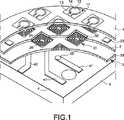
次の用語ワードについて説明する前に、実験を行なったときに用いたタッチプレートを備える触覚ディスプレイの特徴について図1を参照しながら説明することとする。 Before describing the next term word, the characteristics of the tactile display including the touch plate used in the experiment will be described with reference to FIG.
プレート10は、2003年12月3日出願の国際特許出願WO(PCT国際出願番号:PCT/FR 03/50152)に対応する、2002年12月9日出願のフランス特許出願第02−15527号に開示されるプレートに従って作製されるタイプである。本出願に開示する触覚ディスプレイに関する簡単な説明が、先行技術についての記述を参照しながら上の文献において行なわれている。このようなタッチプレートの全ての変形、特にパッドの形状によって変わる変形は本明細書に提示される適用形態に有用である。他の触覚ディスプレイも、これらの触覚ディスプレイを使用してパッド群の状態を個々に制御することができる場合には適切となり得る。先行技術によって定義される触覚ディスプレイは、本出願による情報伝達方法を定義するために最初に行われた研究の間に使用されている。研究は現在も同様の触覚ディスプレイを用いて継続して行なわれているが、触覚ディスプレイはまず、各パッドに接続されるペルチェセル、または互いに隣接するパッドグループを含み、そして次に、個々にペルチェセルをアドレス指定するために使用される第2アドレス指定回路を含む。このような構成では、温度によって変わる更に別の状態を一つのパッドまたはパッドグループに割り当てることができる。図1は、ペルチェセルも備えるこのような触覚ディスプレイの主要構造を集合的に形成する複数の層の拡大透視図を示している。
触覚ディスプレイは、基板6に搭載されるアドレス指定回路を構成するプリント回路層4を備える。層4は絶縁支持体により構成され、絶縁支持体の上には、複数の導電配線41が縦横に形成され、各導電配線はプリント回路のエッジを当該配線のコンタクト端部45に、層3に属するコイル31の端部で接続する。層3は触覚パッド群の制御コイル群31を含む層である。層3は層4の真上に配置される。層3は、螺旋状導電配線32を収容する絶縁支持体33により構成され、これらの配線の各々は、複数のフラットコイル31の内の一つを構成する。このようなコイルの構造はそれ自体が公知であるので、ここでは説明しないこととする。一つのコイル31を構成する導電トラック32の一端部35、例えばこの配線の中心に位置する端部はアドレス指定回路4の導電配線41のコンタクト端部45と接触する。 The tactile display includes a printed
2つの配線41を図1に観察することができる。コイル31の一端部と接触する配線41のコンタクト端部45の内の一方の端部を観察することができるが、他方の端部はコイル群から成る層3によって隠れて見えなくなっている。 Two
アドレス指定回路の各配線41はコイル層3の中の一つの、かつ唯一のコイル31をアドレス指定する。ここに説明する例では、コイル31群から成る層3は8本のラインを含み、各ラインは8個のコイル31を含む。これらのコイルはマトリクス状に形成される。この構成は必須ではない。 Each
コイル群31の配置は、一つのコイルの磁界が、例えば触覚パッド、例えばブレードを構成する可動部品に一つのコイルが対向するので磁界によって作動することになる触覚パッドの位置で大きくなり、そしてこのコイルで制御されない触覚パッドの位置で小さくなるように構成される。 The arrangement of the
電気絶縁層2はフラットコイル群31から成る層3の真上に配置される。この層2は第1セットの凹部21を含む。この第1セットにおけるこれらの凹部21は、複数のブレード12の移動を可能にするように構成され、各ブレードが触覚パッド11を構成する。先行技術においては公知になっていない新規の態様で、層2は第2セットの凹部22を含む。層2における各凹部22を使用してペルチェセル23を保持することができる。図示の例では、4つのセル23が、8×8個の触覚パッド11から成るセットによって構成されるマトリクスの外側エッジの各々に沿って横方向に配置される。これらのセル23は、アドレス指定回路4の補助配線42を使用して同時に制御され、これらの補助配線の内の一つだけが図示されている。これらの配線は図示しない複数のビアに接続され、これらのビアは層3及び2を貫通し、かつ複数のペルチェセルの電気接続手段とのコンタクトポイントで終端する。この実施形態では、タッチプレート10の表面1の温度状態を全体的に変更する。 The electrical
図示しない一の実施形態では、層2は一つの凹部22を各触覚パッド11に対応して含む。この実施形態では、各凹部22及び当該凹部に収容されるセルは、パッド11を構成するブレード12を区切る凹部14の垂直突起を取り囲むリングの形状を有する。 In one embodiment not shown, the
図示しない別の実施形態では、層2は一つの凹部22を、互いに隣接する複数の触覚パッドから成る各グループに対応して含む。この実施形態では、各凹部22及び当該凹部に収容されるセルは、パッド群11から成るグループを構成する、ブレード群12から成るグループを区切る、複数の凹部14から成るグループの輪郭の垂直突起を取り囲むリングの形状を有し、パッド群11から成るグループは前記輪郭内に含まれる。 In another embodiment, not shown, the
図示しない更に別の実施形態では、層2は一つの凹部22を、各ロウまたは各カラムに配列されるパッド群に対応して含む。この実施形態では、各凹部22及び当該凹部に収容されるセルは、2つの連続ラインまたは2つの連続コラムに配列される複数の凹部14の垂直突起に沿って収容される矩形の形状を有し、これらの凹部14は前記連続ラインまたは連続カラムにそれぞれ属する。この実施形態の一の変形例では、1つ、または2つの追加ペルチェセルが最も外側の触覚パッドから成るラインまたはカラムに沿って横方向に配置される。 In yet another embodiment not shown, the
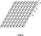
最後に、例えば磁気金属シートにより構成されるタッチプレート10は絶縁層2の真上に設けられ、絶縁層2は凹部21、及びペルチェセル23を収容することができる凹部22を含む。図示の例では、触角感覚を変更する要素群の各々を構成するブレード12は図2に示す例に従って配設される。この図について次に説明することとする。 Finally, the
図2は、タッチプレートの上面図のみを含み、タッチプレートのタッチエリア1を示している。このプレート10は、ライン及びカラムにマトリクス状に配置されるパッド群11を含む。図示の例では、プレートは、1〜8の番号が付された8本のライン、及びa〜hの記号で特定される8本のカラムを含む方形マトリクスにより構成される。 FIG. 2 shows only a
各触覚パッド11は単一ブレード12の形態である。各単一ブレード12の周辺の大部分は、上側表面1がタッチプレート10の表面となる構成の一つの層の連続体から凹部14によって隔絶され、この凹部は、或る部分を除いてブレード12全体を取り囲み、当該部分では、このブレード12がタッチプレート10の連続体に、ブレード12を前記連続体に接続するアーム13を介して接続される。従って、各パッド11はブレード12、及びブレード12をプレート10上の連続体に接続するアーム13により構成される。 Each
実験モデルでは、1本のラインまたは1本のカラムの2つの連続パッドの間の距離は5mmである。平面からはみ出す変形の最大値は100μmである。この変形は、触覚パッドの駆動振幅と呼ばれるものを表わしている。
通過帯域は800Hzである。
各パッドによって生成される最大力は13mNである。
各パッドは他のパッドとは無関係にアドレス指定することができる。In the experimental model, the distance between two consecutive pads of one line or one column is 5 mm. The maximum value of deformation that protrudes from the plane is 100 μm. This deformation represents what is called the drive amplitude of the tactile pad.
The passband is 800 Hz.
The maximum force generated by each pad is 13 mN.
Each pad can be addressed independently of the other pads.
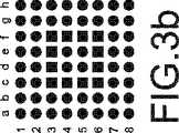
上に説明を行なってきたが、次に、「快適」及び「探索」というワードについて図3及び4を参照しながら説明する。 Having described above, the words “comfort” and “search” will now be described with reference to FIGS.
「快適」感情の場合、例えば20msに等しいパッドの半振動周期Tcの期間を使用することができ、そしてパターン間期間は70msである。次に、「快適」感情を表わすように設計される触覚収束/発散波について図3を参照しながら説明する。この図は、部分A,B,C,及びDを含む。これらの部分の各々は、一つのパターンの一つのイメージを表わす。「快適」感情の場合、パターンは、図3の部分A〜Dの上で表現される4つのイメージから成る。各イメージは64個のパッドを、非アクティブパッドに関してドット記号形態で、そしてアクティブパッドに関して方形記号形態で表わす。イメージAの上では、第1方形の第1輪郭を画定する要素群がアクティブである、別の表現をすると、これらの該要素は振動している。この第1輪郭は最も中心に位置する最小の方形として定義され、この方形は、最初のラインの2つの連続パッドを連結し、次に、これらの2つのパッドの各々を直近の垂直方向パッドに連結して、最初のラインに続く2番目のラインの2つの連続パッドに到達し、そして最後に、到達した2つの連続パッドを連結する一つのセグメントが得られることにより形成することができる。この中心方形輪郭は、方形d4,e4,e5,及びd5を連結することにより形成されるラインである。 For “comfortable” emotions, a period of pad half-vibration period Tc equal to 20 ms, for example, can be used, and the inter-pattern period is 70 ms. Next, tactile convergence / diverging waves designed to represent “comfortable” emotions will be described with reference to FIG. This figure includes parts A, B, C, and D. Each of these parts represents one image of one pattern. In the case of “comfortable” emotions, the pattern consists of four images represented on parts A to D of FIG. Each image represents 64 pads in dot symbol form for inactive pads and in square symbol form for active pads. On image A, the elements defining the first contour of the first square are active. In other words, these elements are oscillating. This first contour is defined as the smallest centrally located rectangle that connects two consecutive pads of the first line and then each of these two pads to the nearest vertical pad. It can be formed by joining and reaching two consecutive pads of the second line following the first line, and finally obtaining one segment connecting the two consecutive pads reached. This central square contour is a line formed by connecting squares d4, e4, e5, and d5.
第2イメージ、すなわちイメージBでは、次に大きいサイズを持ち、かつ第1方形を完全に包含する第2方形を形成するパッド群がアクティブである。第3イメージ、すなわちイメージCでは、第2方形よりも大きいサイズを持ち、かつ第2方形を完全に包含する第3方形を形成するパッド群がアクティブである。最後に、第4イメージ、すなわちイメージDでは、第3方形よりも大きいサイズを持ち、かつ第3方形を完全に包含する第4方形を形成するパッド群がアクティブである。図示の例では、タッチプレート10の外周に沿って位置する全てのパッド11が含まれる。 In the second image, ie, image B, a group of pads forming the second rectangle having the next largest size and completely including the first rectangle is active. In the third image, ie, image C, a group of pads forming a third square having a size larger than that of the second square and completely including the second square is active. Finally, in the fourth image, ie, image D, the pads that form a fourth rectangle that is larger in size than the third square and completely encompasses the third square are active. In the illustrated example, all the
従って、「快適」という言葉の語感を伝達するために、各イメージは0.9msだけ継続し、そして2つの連続イメージの間の期間は0.1msである。連続するイメージの間の期間中は、どのパッドもアクティブではない、別の表現をすると、どのパッドも振動しない。従って、直ぐ上に説明した例では、4つのイメージを有する一つのパターンを持つことができ、当該パターンはイメージA,B,C,及びDにより構成される。パターンはイメージAから始まり、かつイメージA,B,C,及びDから成る同じシーケンスを繰り返す形で繰り返される。7つのイメージから成るパターンを持つこともできる、すなわちイメージA,B,C,そしてDの順に進み、そして逆の順に、別の表現をすると、C,B,そしてイメージAの順に戻る構成のパターンを持つこともできる。
従って、この最後のパターンは7msだけ続く。Thus, to convey the sensation of the word “comfortable”, each image lasts 0.9 ms and the period between two consecutive images is 0.1 ms. During the period between successive images, no pad is active, in other words no pad vibrates. Therefore, in the example described immediately above, it is possible to have one pattern having four images, and the pattern is composed of images A, B, C, and D. The pattern is repeated starting with image A and repeating the same sequence of images A, B, C, and D. It is also possible to have a pattern consisting of seven images, that is, a pattern that proceeds in the order of images A, B, C, and D, and in reverse, in another order, returns in the order of C, B, and image A. You can also have
This last pattern therefore lasts for 7 ms.
パターン間期間は70msであるので、一つのパターンの周期は7ms+70ms=77msとなる。 Since the inter-pattern period is 70 ms, the period of one pattern is 7 ms + 70 ms = 77 ms.
半振動周期の期間Tcが20msであるということは、アクティブパッドが、例えば一つのイメージの期間が0.9msであるので、一つのイメージの期間全体に渡ってハイ状態のまま隆起していることを意味する。イメージ間の中立状態に戻すコマンドは、触覚パッドの振動周期を決定するパルスコマンドよりも高い優先度を持つ。これは、触覚パッド11が中立状態、例えばロー状態に戻り、例えばタッチプレートと次の20ms全体に渡って同一平面になることを意味する。 That the period Tc of the half-vibration period is 20 ms means that the active pad is raised in a high state over the entire period of one image because the period of one image is 0.9 ms, for example. Means. The command to return to the neutral state between images has a higher priority than the pulse command that determines the vibration period of the haptic pad. This means that the
従って、直ぐ上に説明したパターンでは、パターンを初期時点t0で送信し始める場合、第1方形の4つのパッドがロー状態からハイ状態に変化する。第1方形のこれらの4つのパッドはロー状態に0.9ms後に戻り、そしてロー状態を維持する。同じ事象が第2方形のパッド群にmsで表わされる次の期間に生じ、同様の事象が第3及び第4方形に関して生じる。 Therefore, in the pattern described immediately above, when the pattern starts to be transmitted at the initial time point t0, the four pads of the first square change from the low state to the high state. These four pads of the first square return to the low state after 0.9 ms and remain in the low state. The same event occurs on the second square pad group in the next period, expressed in ms, and a similar event occurs for the third and fourth squares.
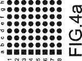
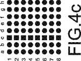
次に、「探索」というワードについて図4を参照しながら説明する。
一つのイメージの期間とイメージ間時間の合計は20〜90msである。Next, the word “search” will be described with reference to FIG.
The sum of the period of one image and the time between images is 20 to 90 ms.
例えば、50msのイメージ期間、及び5msのイメージ間期間を使用することとする。従って、最大パターン間時間TIMは100.8*55−200=5344msとなり、Tc=10.20*35/70=5.1msが成り立つ。For example, an image period of 50 ms and an inter-image period of 5 ms are used. Therefore, the maximum inter-pattern time TIM is 100.8* 55−200 = 5344 ms, and Tc = 10.20* 35/70 = 5.1 ms.
イメージAでは、最左列である第1カラム(a)のパッドのみが振動する。これらのパッドは5.1ミリ秒の半振動周期で振動する、別の表現をすると、これらのパッドはイメージAが継続している間に約10回だけ隆起し、そして戻る。これらのパッドはイメージ間周期の間に、そしてイメージ間周期の後にロー状態のままになっている。55msが経過した後、最左列から2番目のカラム(b)のパッドが第1カラム(a)のパッド群と同じ態様でイメージBに示すように振動し始め、3番目のカラム以降にも同様の事象が生じ、最後のカラム(h)は、第1カラム(a)が振動し始めた後、55*8msが経過した後にイメージHに示すように振動を停止する。この時点で、同じイメージシーケンスが始まるが、今度は右から左に向かって始まる。イメージHが終了した後、次のイメージはイメージG、次にイメージFなどと続き、最後にイメージAが再び現われる。次に、パターンが終了し、そして5.344秒の待機時間となり、この待機時間の間は、全てのパッドが、同じパターンが再開する前に中立状態になっている。In image A, only the pad in the first column (a), which is the leftmost column, vibrates. These pads vibrate with a half-vibration period of 5.1 milliseconds. To put it another way, these pads rise and return about 10 times while image A continues. These pads remain low during the inter-image period and after the inter-image period. After 55 ms, the pad of the second column (b) from the leftmost column starts to vibrate as shown in image B in the same manner as the pad group of the first column (a), and after the third column. A similar event occurs and the last column (h) stops oscillating as shown in image H after 55* 8 ms has elapsed after the first column (a) begins to oscillate. At this point, the same image sequence begins, but this time from right to left. After image H ends, the next image follows image G, then image F, etc., and finally image A appears again. Next, the pattern ends and there is a 5.344 second waiting time during which all pads are in a neutral state before the same pattern resumes.
直ぐ上に説明したパターンは15個のイメージA,B,C,D,E,F,G,H,G,F,E,D,C,Bを順番に含む。イメージAからイメージHの順方向経路に続いてイメージHからイメージAに戻るのではなく、イメージAからイメージHの順方向経路を採り、次に同じ順方向経路を再開すると決定された場合には、イメージを8個しか持たないことも可能である。 The pattern just described includes 15 images A, B, C, D, E, F, G, H, G, F, E, D, C, B in order. If it is decided to take the forward path from image A to image H and then resume the same forward path instead of returning from image H to image A following the forward path from image A to image H It is possible to have only 8 images.
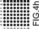
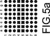
次に、図5を参照しながら示される例について説明する。この例では、ラインの数が奇数である場合の第1イメージを除き、常に2ライン分のアクティブ触覚パッドが存在する。図5の部分Aに示す第1イメージでは、2つのアクティブラインは、タッチエリアの中心に最も近い番号4及び5が付された2つの連続するラインである。ラインの数が奇数であった場合、中心に最も近いラインのみがアクティブになっていることになる。Bに示される第2イメージでは、番号3及び6が付されたラインがアクティブであり、これらのラインは、第1イメージで作動したラインの後に続く、連続するラインである。これらの2つのラインは、第1イメージの間に作動した2つのラインよりも、最も外側のラインに近い。第3イメージの間、外側の次の2つの連続するラインが作動し、そして最終的にイメージDでは、最も外側のラインが作動する。次に、パターンはイメージDからイメージCに戻る形で継続し、同様にして最終的にイメージAに戻る。従って、パターンは、イメージA,B,C,D,C,B,及びAから成るシーケンスを含む。最後に、同じパターンがパターン間時間が経過した後に繰り返される。 Next, an example shown in FIG. 5 will be described. In this example, there are always two lines of active haptic pads, except for the first image where the number of lines is odd. In the first image shown in part A of FIG. 5, the two active lines are two consecutive lines numbered 4 and 5 that are closest to the center of the touch area. If the number of lines is an odd number, only the line closest to the center is active. In the second image shown in B, the lines numbered 3 and 6 are active, and these lines are successive lines following the line that was activated in the first image. These two lines are closer to the outermost line than the two lines that were activated during the first image. During the third image, the next two consecutive lines outside are activated, and finally in image D, the outermost line is activated. The pattern then continues from image D back to image C, and finally returns to image A as well. Thus, the pattern includes a sequence consisting of images A, B, C, D, C, B, and A. Finally, the same pattern is repeated after the inter-pattern time has elapsed.
従って、このパターンに関して、最も中心の1つのライン、または最も中心の2つのラインが第1イメージにおいて作動し、ラインが1つになるか2つになるかは、ラインの数が奇数または偶数であるかどうかによって変わり、次に、第2イメージでは、前のイメージの間に作動していたラインの外側の2つの連続するラインが作動し、同様の事象が、イメージnの最も外側のラインに到達するまで続き、次に、手順は第1イメージに戻るまで、イメージn−1,n−2などと続くイメージを再表示することにより中心に向かって戻る。図3及び4を参照しながら説明した事例に示すように、例えばイメージA〜Dから成るシーケンスが示すように中心から周辺に向かい、次に、イメージAから再開するような順方向経路のみを採る、または中心から周辺に向かった後、単純に、イメージDからイメージAに戻る経路を採ることも可能である。 Thus, for this pattern, the most central line, or the two most central lines, will operate in the first image and whether the number of lines will be one or two is an odd or even number of lines. Then, in the second image, two consecutive lines outside the line that was active during the previous image are activated, and a similar event occurs in the outermost line of image n. The procedure continues until it reaches, and then the procedure returns towards the center by redisplaying the image n-1, n-2, etc., and so on, until it returns to the first image. As shown in the example described with reference to FIGS. 3 and 4, for example, only the forward path is taken from the center to the periphery as shown by the sequence of images A to D and then resumed from image A. It is also possible to simply take a path from image D back to image A after going from the center to the periphery.
図4及び5を参照しながら説明したパターン例では、ラインの代わりにカラムを使用する、またはカラムの代わりにラインを使用することが当然可能である。アクティブラインを、pを法とする数だけずらすことにより連続するイメージを進むこともできる、別の表現をすると、例えばこれらの例で説明したように単一ラインではなく、pライン分だけラインをずらすことにより、一つのイメージから次のイメージに移動することもできる。 In the example pattern described with reference to FIGS. 4 and 5, it is naturally possible to use columns instead of lines, or lines instead of columns. Another way of moving the active line by moving the active image by a number modulo p is to move forward images, for example, instead of a single line as described in these examples, the lines are moved by p lines. By shifting, you can move from one image to the next.
上に説明した例によれば、例えば以下のような多数のパラメータを変更することにより用語ワードを定義することができることは明らかである。
−イメージのデザイン。このデザインはパッド振動周波数、パッドに加わる力、前記パッドの隆起位置、またはパッドの平面位置によって変わる各パッドの温度に対応する。
−イメージ期間。
−複数のイメージの間の期間。
−連続するイメージのデザイン、及び1つのパターンを定義するイメージの数。
−複数のパターンの間の期間。According to the example described above, it is clear that the term word can be defined by changing a number of parameters, for example:
-Image design. This design corresponds to the temperature of each pad depending on the pad vibration frequency, the force applied to the pad, the raised position of the pad, or the planar position of the pad.
-Image period.
-A period between multiple images.
-The number of images defining a continuous image design and one pattern.
A period between patterns.
次に、デバイスの幾つかの例について説明することとするが、これらの例では、タッチプレートを備え、かつイメージシーケンスによって構成されるパターンを、コマンドワードの受信に続いて生成する機能を備えるサーバが配設される触覚ディスプレイを導入することによって、前記デバイスに更に別の高性能機能が付与され、かつデバイスの基本機能の効率が高くなる。 Next, some examples of devices will be described. In these examples, a server having a touch plate and a function of generating a pattern constituted by an image sequence following reception of a command word. By introducing a tactile display in which the device is arranged, another high performance function is given to the device, and the efficiency of the basic function of the device is increased.
図6及び7はそれぞれ、触覚ディスプレイのレイアウトを示し、触覚ディスプレイはタッチプレート10を携帯電話機の持ち運び部分の上に備える。持ち運び部分は、無線電話機または電話機ハンドセットの持ち運び部分とすることもできる。 6 and 7 each show the layout of a tactile display, where the tactile display comprises a
図6では、タッチプレート10は前面58に配置され、前面は電話機50のヘッドセット及びマイクロホンを含む。図7では、タッチプレート10は電話機50の側面に配置される。この配置によって、手の指または手のひらとの接触が可能になり、手の指または手のひらのいずれと接触するかは、電話機50がどのように保持されるかによって変わる。最後に、タッチプレート10を電話機50の背面に配置して、手のひらと接触するようにすることもできるが、この様子は図には示していない。伝達情報はパターンシーケンスにより構成されるので、例えば点字読取に関する事例と同じように、人体の一部分がタッチプレートと接触して、複数の触覚パッドを明確に区別することができるようにする、という必要はない。 In FIG. 6, the
図に記号で示す回路に関して、触覚ディスプレイがそのタッチプレート10を備える構成の触覚ディスプレイが配設された電話機50は、流れ込むフローを受信し、そしてデコードする受信機51と、マルチプレクサ52と、を備え、マルチプレクサは、デコード情報を受信し、そして当該情報の送信先を、情報の性質によって変わる形でアナログ変換装置に切り替え、アナログ変換装置は、情報の再生に必要な、例えば画面に表示することができるデータ、またはハンドセットによって復元される音声データの再生に必要なトランスデューサに適する。電話機がタッチプレート付き触覚ディスプレイを備える場合、マルチプレクサは、触覚情報に固有の出力53を含む。電話機は更にサーバ54を備える。サーバ54にはソフトウェアモジュール57が配設され、ソフトウェアモジュールは、各個々のグローバルコマンド、例えば「触発作用」のようなコマンドワードを電気信号の一連の値及び状態に変換し、これらの電気信号はパッドを制御する各コイル31宛てに送出される、または可能であればペルチェセル23宛てにプレート10上のパッド11から成るアドレス指定回路4を通して送出される。ソフトウェアモジュール57は、この動作を行なうために複数の命令を含み、これらの命令を組み合わせて一つのルーチンを作成し、この場合、一つの個別ルーチンが各個々のグローバルコマンドに対応する。ルーチン内の第1命令のメモリアドレスは個々のグローバルコマンドによって変わる。別の構成として、ソフトウェアモジュール57は複数の命令を含み、これらの命令を組み合わせて一つのルーチンを作成し、この場合、一つの個別コマンドが一つのルーチンに対応し、これらの命令は、指定メモリアドレスでのパラメータの値に対するサーチを指示するサーチ命令を含む。後者の処置方法は、或るワードが与えられる場合、ユーザはイメージ期間、パッド振動周波数、イメージ間期間のようなパラメータ値、及び一般的には、タッチプレートによって与えられる印象の変更に影響する全てのパラメータを、パッド群がこれらのパラメータに関連してアクティブになるように指定することができるという利点を有する。電気信号の一連の値及び状態は、或る状態を各パッド11に付与する。異なるパッド11の異なる状態はタッチパッド10上のデザインを形成する。前記デザインは、所定期間の最後に、全てのパッドが中立状態に戻る構成の所定期間に渡って、または新規コマンドの受信時に終了する或る期間に渡ってそのままの状態を維持し、次にパッドは状態を変えて、前記新規グローバルコマンドによって遷移した状態になり、そして新規デザインを形成する。 With respect to the circuit shown symbolically in the figure, the
ソフトウェアモジュール57は更に、第1デザインを所定期間に渡って維持し、第1デザインを更新し、そして第1デザインを第1デザインとは異なる、または第1デザインと同じ第2デザインに、正の、またはゼロの所定期間に渡る中立状態に戻った後に置き換え、これと同じ動作を、最後の1つ前のデザインとは異なる、または最後の1つ前のデザインと同じ最後のデザインまで続け、一連のデザインのタイミングは、各デザインの期間、及びデザイン群を、一連のイメージを形成する連続ランクに分離する期間に合わせ、一連のイメージは一つのパターンを形成し、そしてソフトウェアモジュール57は更に、このように形成されるパターンを、いずれかの正の期間を持つ、または一つのパターンの連続図の間の期間に等しいパターン間時間間隔(TiM)で、所定回数だけ、または所定期間に渡って繰り返す。 The
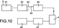
図9は別のデバイス60を示し、このデバイスの上には、触覚ディスプレイが配置され、触覚ディスプレイはタッチプレート10及び当該プレートの制御サーバを含む。前記デバイスはシステム手帳60である。タッチプレート10は表面68の一部分の上に設けられ、当該部分には、ユーザが当該ユーザの手の一部分で触れることができる。前記システム手帳60は、図10に記号化して示される受信機回路61を内部に含み、前記受信機回路61は特に、位置特定情報を地上ビーコンまたは衛星ビーコンから受信し、そして前記受信機61の地理的位置を推定する機能を備える。システム手帳にはマルチプレクサ62が設けられ、マルチプレクサ62は受信機回路61によってデコードされる情報を受信し、そして情報の送信先を、当該情報の性質によって変わる形で、受信する情報をアナログ物理量に変換する手段を制御するデバイスに切り替える。詳細には、マルチプレクサ62は地理的位置情報を受信する。詳細には、マルチプレクサ62には、地理的位置情報を受信する出力63が設けられる。マルチプレクサ62からの出力63は接続手段65を介して、触覚デバイス10を制御するサーバ64に接続される。システム手帳は更にメモリ66を含み、メモリ66には、2次元地図または3次元地図が読み込まれる。訪問地リストを読み込むこともできる。訪問地リストがメモリ空間66に読み込まれると、触覚ディスプレイを制御するソフトウェアモジュール67は、タッチプレート10の触覚パッド群11にこの訪問地リスト情報によって変わる形で指示して、訪問地リストの地理的形状、または受信機61が位置する場所である訪問地リストの一部分のみの地理的形状を再生させる。受信機61の実際の地理的位置に対応するパッドは決められたの方法で制御される、例えば特定の振動周波数で制御される。このようにして構成されるシステム手帳によって、部分的な視力障害を持つ人が自分の位置を自然環境の中において特定し易くなる。部分的な視力障害を持つ人が移動すると、この移動はGPS受信機61及びソフトウェアモジュール67を使用して、表示される訪問地リストの上にもう一度再生されることになり、そして決められた方法で振動する触覚パッドがタッチプレート10上を移動する。障害物は、異なる周波数で振動する触覚パッド、または隆起モードのコマンドを受信する触覚パッドのいずれかにより表示される。これにより、部分的な視力障害を持つ人は自分の位置を、所定環境において少なくとも相対的に特定することができる。これによって更に、或るワード、例えば「真っ直ぐに進む」または「左に曲がる」などを意味するワードを送信することにより方向指示メッセージを表示する手段が提供される。明らかなことであるが、各ワードに対応する特定パターンが上述のように設けられる。従って、部分的な視力障害を持つ人は、自分が左に、右に、または或る角度の方向に、例えば直線状の振動パッドを所定の協定周波数で左から右に向かってタッチエリア1上を移動させることにより、曲がる必要があるという通知を、いずれの時点においても受け取ることができる。従って、人が学習し、そして予め記憶することができるナビゲーション方法のプログラムを作成することができる。 FIG. 9 shows another
図11は別のデバイス70を示し、このデバイスの上には、触覚ディスプレイが搭載され、触覚ディスプレイはタッチプレート10及び当該プレートの制御サーバを含む。前記デバイスはコンピュータマウス70である。タッチプレート10は表面78の一部分の上に設けられ、当該部分には、ユーザが当該ユーザの手の一部分で触れることができる。このタッチプレート10は、マウスの複数のボタンの内の一方(または、両方)の上に配置することができる。当該タッチプレート10はマウスを把持するときに指に触れる領域でもあることから、マウスの各側に配置することもできる。前記マウス70は、図12に記号化して示されるように受信機回路71をその内部に含み、この受信機回路は、前記マウスを操作することによって制御される「人差し指」が示す位置特定情報を受信する。詳細には、マルチプレクサ72は、受信機回路71によってデコードされる位置特定情報を受信する。マルチプレクサ72は、情報の送信先を、当該情報の性質によって変わる形で、受信情報をアナログ物理量に変換する手段を制御するデバイスに切り替える。詳細には、当該情報は、例えば特定記号によって変わる位置を表示する視覚情報とすることができ、この特定記号は、位置、音、または他の情報によって異なってくる。マルチプレクサ72からの出力73を使用してマウスのマルチプレクサ72を、接続手段75を介して、触覚デバイス10のサーバ74に接続することができる。サーバ74にはソフトウェアモジュール77が設けられ、ソフトウェアモジュール77は触覚ディスプレイを、マウスの位置、及び当該位置の性質によって変わる形で制御する。位置の性質とは、異なるコマンドまたはアイコン、またはウィンドウの上下端、或いは他の要素に対応する位置を指す。 FIG. 11 shows another
従って例えば、部分的な視力障害を持つ人は、マウスのカーソルがアイコン選択領域上に位置しているかどうかを判断する方法を最初に定義することができる。新規パターンの形態の触覚関連ワードを付加して(従って、パターンに影響する種々のパラメータを変更することにより)、各ボタンを他のボタンから区別することもできる。例えば、上に説明した「探索」触覚関連ワードは、Windows(登録商標)スタートメニューのサーチボタンに関連付けることができ、そして別の触覚関連ワードは、《“OKまたはVALIDATE》タイプボタンに関連付けることができる。 Thus, for example, a person with partial vision impairment can first define a method for determining whether the mouse cursor is positioned over the icon selection area. Each button can also be distinguished from other buttons by adding tactile-related words in the form of new patterns (and thus changing various parameters that affect the pattern). For example, the “search” haptic-related word described above can be associated with a search button in the Windows® start menu, and another haptic-related word can be associated with a << “OK or VALIDATE” type button. it can.
詳細には、このようにして搭載されるタッチプレート10によって、部分的な視力障害を持つ人は、異なるウィンドウの輪郭をなぞる感触を得ることもできる。最後に、タッチプレート10を制御するソフトウェアモジュール77に調整を加えて、表面の異なる肌触り、または手探り感を与えることができる。これによりユーザは、例えば当該ユーザが現時点で、2つの異なるウィンドウを表わす2つの異なるゾーンを探索していることを認識することができる。 Specifically, the
ソフトウェア制御モジュール77付きのタッチプレート10は専用周辺機器の上に、またはコンピュータ80のキーボード89のゾーン88の上に配置することもできる。図13に示すこの構成によって、部分的な視力障害を持つ人は、自分のコンピュータを使用してテキストタイプのファイルを読み取ることができる。ソフトウェアモジュールは、ASCII文字で表記されるテキストタイプのファイルを点字ファイルに変換する。従って、前記ファイルは順番に文字毎に、またはワード毎に、或いはライン毎に表示され、いずれの形式で表示されるかは、前記表面1上のタッチプレート10の表面1によって変わる。上に定義した触覚関連ワードは他の触覚情報と一緒に同じ表面1の上に表示して、ユーザと当該ユーザのオペレーティングシステムとの間の相互作用を向上させる、またはインターネット上のアプリケーションを動作させている間の相互作用を向上させることができる。ここで、コンピュータマウスの場合は、上に述べた全ての機能は、タッチプレートをキーボード位置に配置する場合に置き換えて考えることができることに注目されたい。 The
図14及び15は別のデバイス90を示し、このデバイスの上には、少なくとも一つの触覚ディスプレイが配置され、触覚ディスプレイはタッチプレート10及び当該プレートの制御サーバを含む。この場合、デバイスは車両のハンドル90である。 FIGS. 14 and 15 show another
図14に示す例では、2つのタッチプレート10を設ける。2つのプレートを制御するためには単一のソフトウェアモジュールを備えるだけで十分であるので、単一のタッチプレート10を2つの部品として設けることも考えられる。ソフトウェアモジュールをハンドルに搭載する必要はない。詳細には、ソフトウェアモジュールは車載コンピュータのメモリ領域に配置することができる。 In the example shown in FIG. 14, two
自動車環境におけるドライバの視覚的環境認知に対する要求が益々強くなっている。例えば、タッチプレート10を車両のハンドルに設けることにより、情報をドライバに、ドライバが道から眼をそらす必要を生じることなく、かつ車載ラジオの聞き取りを中断することもなく伝達することができる。 There is an increasing demand for visual environment recognition by drivers in the automotive environment. For example, by providing the
従って、ハンドルに取り付けられる2つのタッチプレート10によって、ドライバは触覚情報を、例えばドライバの2つの手の親指で感知することができる。例えばこの場合においては、一例としてタッチプレートをナビゲーションシステム搭載車両に設けて、ドライバを、「右に曲がりなさい」または「左に曲がりなさい」のような知覚メッセージによって支援することができる。このようなデバイスのソフトウェア構成は、システム手帳60について説明したソフトウェア構成と同じである。この場合、位置特定情報は車両に固有のナビゲーションシステムから送出される。 Accordingly, the two
図15に示す事例では、タッチプレート10はハンドルの外形形状に一致する。従って、例えば複数の触覚パッドはハンドルの輪郭周辺に、またはハンドルの一部分、例えばドライバが普通、ドライバの手を置く下側部分にのみ分散配置される。従って、ドライバは、ハンドルを握ったときに触覚情報を知覚することができる。センサシステムが車両に既に組み込まれていて、障害物が車両の後方、前方に接近する事象、更には両側に接近する事象も検出することができる。これらのセンサによって生成される情報は特に、タッチプレート10のソフトウェアコマンドモジュールに送信されて、ドライバに、例えば障害物が存在している事実、及び車両に対する障害物の位置を、ハンドルに取り付けられた触覚パッドによって通知することができる。従って、車両の右側の連続白線ラインを跨っているかどうかを判断するセンサを使用する場合、ドライバには、この事象が発生する時点を知覚メッセージによって、例えばハンドルの右側部分に配置されるタッチプレート10の触覚パッド11への圧力知覚メッセージの送信を開始することによって通知することができる。全てのこれらの例は、ドライバがこれらの例を眼で追う必要を伴なうことのないナビゲーション支援例であると考えることができる。 In the case shown in FIG. 15, the
Claims (19)
Translated fromJapanese(a)デジタルワードの構成で伝達される触覚情報を、所定数のイメージのシーケンスとして定義し、所定数のイメージは、全体として1つのパターンを形成し、
各イメージは、前記パターンにおいて、順番付がされており、
各パターンは、
−連続するイメージのデザインと、
−前記シーケンスにおけるイメージの順番に応じた、各イメージの期間と、
−連続するイメージ間の期間と、
−連続するパターン間の期間と、
によって定義され、
前記第1デザインにおける前記触覚パッドと、前記第2デザインにおける前記触覚パッドとが、第1及び第2イメージのそれぞれの同じ平面的位置で、それぞれ同じ状態の場合、前記第1及び第2イメージに対応する前記デザインは、互いに同一であり、同じ状態でない場合、前記第1及び第2イメージに対応する前記デザインは、互いに異なり、
(b)
前記ワードは、ビーコンに先立って、制御サーバ(54、64、74)に送信され、
前記ビーコンは、当該ビーコンに続いて、前記サーバにデータが送られることを示し、
(c)
前記サーバが、前記ワードを受信すると、一連の命令が起動され、
当該一連の命令は、前記ワードに応じた開始アドレスを有し、
前記一連の命令は、表示されるべき前記ワードに対応する前記パターンを、全体として形成する、連続するイメージを表示するのに用いられ、
前記一連の命令は、所定回数、又は、所定期間に渡って、同一のパターンを表示するために繰り返される、
触覚情報伝達方法。A method for transmitting tactile information to a touch plate (10) of a tactile display includinga plurality of tactilepads (11), wherein the touch plate (10) iscontrolled by a control server (54, 64, 74), and in this way,
(A) The haptic information transmitted in the configuration of the digital wordis defined as a sequence of a predetermined number of images, and the predetermined number of images forms a pattern as a whole,
Each image is ordered in the pattern,
Each pattern is
-and the designof successiveimages,
-The duration of each imageaccording to the order of the images in the sequence;
-The periodbetween successiveimages ;
-The periodbetween successivepatterns ;
Defined by
When the haptic pad in the first design and the haptic pad in the second design are in the same state at the same planar position of the first and second images, respectively, the first and second images The corresponding designs are identical to each other, and if not the same state, the designs corresponding to the first and second images are different from each other,
(B)
The word issent to thecontrol server (54, 64, 74)prior tothe beacon,
The beacon indicates that data is sent to the server following the beacon;
(C)
Theserver,upon receivingtheword, a sequence of instructions is started,
The series of instructions hasa start addressaccording to the word,
It said sequence of instructions,the pattern corresponding tothe wordto bedisplayed, to formas awhole,used to display the successiveimages,
The series of instructions isrepeatedto display thesame patterna predetermined number of timesor over a predetermined period.
Tactile information transmission method.
当該イメージは、所定回数繰り返され、所定の前記イメージ間の期間では、全てのパッド(11)が非アクティブである、
請求項1に記載の触覚情報伝達方法。The pattern isformed from a single image in which aplurality of pads (11) are active;
The image isrepeateda predetermined number of times, and all pads (11)are inactiveduring a predetermined periodbetween the images.
The tactile information transmission method according to claim 1.
当該イメージは、所定回数繰り返され、所定の前記イメージ間の期間では、全てのパッド(11)が非アクティブであり、
前記パターンが繰り返される場合、前記パターン間の期間TIMは、前記イメージ間の期間とは異なる、
請求項1に記載の触覚情報伝達方法。Thepattern, all pads (11)are formed from a single image Ru activeder,
The image isrepeateda predetermined number of times, and all the pads (11)are inactiveduring a predetermined periodbetween the images,
If the pattern isrepeated, a period TIM between the patternis different from the period between the images,
The tactile information transmission method according to claim 1.
第1順方向イメージでは、アクティブなパッド(11)が第1多角形の頂点を形成し、
前記第1多角形は、複数のアクティブなパッド(11)のペアを結ぶ閉じたラインから成り、
第2順方向イメージでは、アクティブのパッド(11)が第2多角形の頂点を形成し、
前記第2多角形は、複数のアクティブなパッド(11)のペアを結ぶ閉じたラインから成り、
前記第2多角形は、前記第1多角形と相似であり、かつ第1多角形を完全に包含し、
この構成が、アクティブなパッド(11)が、最大多角形の頂点を形成する最後の順方向イメージまで適用され、
前記最大多角形は、複数のアクティブのパッド(11)のペアを結ぶ閉じたラインから成り、
前記最大多角形は、前記第1及び第2多角形と相似であり、かつ最後の多角形と同じ方法により作成される前記第1及び第2多角形と相似である、最後から2番目の多角形を完全に包含し、
前記最後の多角形は、連続する触覚イメージが出力されるタッチプレート(10)の上に形成することができる最大の多角形である、
請求項1記載の触覚情報伝達方法。The pattern is composed of a sequence ofimages moving in the forward direction(hereinafter referred to as forward images),
In the first forward image, the activepad (11) forms the vertex of the first polygon,
The first polygon consists ofa closedline connecting a pluralityof pairs of activepads (11),
In the second forward image, the activepad (11) forms the vertex of the second polygon,
The second polygon consists ofa closedline connectinga pluralityof pairs of activepads (11),
The second polygonis similar to the first polygon, and fully encompasses the firstpolygon,
This configuration, theactive pad (11)is applied to the end of the forward image to form a vertex of the maximum polygon,
The maximum polygon consists ofa closedline connectinga pluralityof pairs of activepads (11),
The maximumpolygon, said a similar to the first and second polygons, and is similar to the last ofsaid first and second polygons are created in the same manner aspolygonal, penultimate multi Completely encompassing the square,
The last polygon is the largest polygon that can be formed on the touch plate(10) from which successive haptic images are output.
The tactile information transmission method according to claim 1.
第1順方向イメージでは、アクティブなパッド(11)が第1多角形の頂点を形成し、
前記第1多角形は、複数のアクティブなパッド(11)のペアを結ぶ閉じたラインから成り、
第2順方向イメージでは、アクティブなパッド(11)が第2多角形の頂点を形成し、
前記第2多角形は、複数のアクティブなパッド(11)のペアを結ぶ閉じたラインから成り、
前記第2多角形は、前記第1多角形と相似であり、かつ前記第1多角形を完全に包含し、
この構成が、アクティブなパッド(11)が、最大多角形の頂点を形成する最後の順方向イメージまで適用され、
前記最大多角形は、複数のアクティブなパッド(11)のペアを結ぶ閉じたラインから成り、
前記最大多角形は、前記第1及び第2多角形と相似であり、かつ最後の多角形と同じ方法により作成される前記第1及び第2多角形と相似である、最後から2番目の多角形を完全に包含し、
前記最後の多角形は、連続する触覚イメージが出力されるタッチプレート(10)の上に形成することができる最大の多角形であり、
最後の順方向イメージの後には戻り方向イメージが続き、
第1戻り方向イメージは、最後から2番目の順方向イメージであり、
この構成が、第1順方向イメージである最後の戻り方向イメージまで適用される、
請求項1記載の触覚情報伝達方法。Thepattern, forward image, anda direction opposite to the forward direction, the image to be moved toward the back direction (hereinafter,referred to as backward directionimages) is constituted by a sequence consistingof,
In the first forward image, the activepad (11) forms the vertex of the first polygon,
The first polygon consists ofa closed line connectinga pluralityof pairs of activepads (11),
In the second forward image, the activepad (11) forms the vertex of the second polygon,
The second polygon consists ofa closedline connectinga pluralityof pairs of activepads (11),
The second polygonis similar to the first polygon, and fully encompassesthe firstpolygon,
This configuration, theactive pad (11)is applied to the end of the forward image to form a vertex of the maximumpolygon,
The largest polygon consists ofa closedline connectinga pluralityof pairs of activepads (11),
The maximumpolygon, said a similar to the first and second polygons, and is similar to the last ofsaid first and second polygons are created in the same manner as polygonal, penultimate multi Completely encompassing the square,
The last polygon is the largest polygon that can be formed on the touch plate(10) where a continuous haptic image is output;
Thevapor return directionthe image is continued after thelast of the forwardimage,
The first return image isthe second forward image fromthe end,
This configuration is applied up to the last return image which is the first forward image.
The tactile information transmission method according to claim 1.
第1順方向イメージでは、アクティブなパッド(11)は、プレート上のパッド(11)の内の一つのパッドを含み、かつ第1直線ラインに沿って配列されるパッドであり、
前記第1直線ラインは、所定の方向に平行であり、
前記方向は、タッチプレート(10)上の少なくとも一つのパッド(11)に関して、当該方向に平行なラインの内の少なくとも一つのラインが、少なくとも2つのパッド(11)を含むように決定され、
第2順方向イメージでは、アクティブなパッド(11)は、プレート(10)上のパッド(11)の内の一つのパッドを含み、
第2直線ラインは、第1直線ラインに平行であり、更には、第1直線ラインから決められた距離だけ離れており、
そしてこの構成が最後の順方向イメージまで適用され、
最後の順方向イメージでは、アクティブのパッド(11)がタッチプレート(10)上のパッド(11)の内の一つのパッドを含み、
最後の直線ラインは、第1直線ラインに平行であり、更には最後から2番目の直線ラインから決められた距離だけ離れており、
当該直線ラインは、この直線ラインから、同じ方向に上記決められた距離だけ離れた次の直線ラインが、どのパッドも含まないので最後のラインとなる、
請求項1記載の触覚情報伝達方法。The pattern is formed by a sequence ofa plurality of changingimages from the first forward image to the end of the forwardimage,
In the first forward image, theactive pad (11)comprises one pad of thepad on the plate (11), and apad which is arranged along a firststraight lineline,
The first straight line is parallel to a predetermined direction;
The direction, with respect to at least one of the pads on the touch plate (10) (11), at least one line of the parallellines inthe direction, are determined to include at least two pads(11),
In the second forward image, the activepad (11)includes one of thepads (11) on the plate (10),
The second straight line is parallel to the firststraight line, and furtheraway from the firststraight line by a determined distance,
And this configuration is applied until the last forward image,
In the final forward image, the activepad (11)includes one of thepads (11) on thetouch plate (10),
The last straight line is parallel to the firststraight line and furtheraway from the laststraight line by a determined distance,
The straight line is the last line becausethe next straight lineaway from the straight line bythe determined distancein the samedirection does not include any pads.
The tactile information transmission method according to claim 1.
第1順方向イメージでは、アクティブなパッド(11)は、プレート上のパッド(11)の内の一つのパッドを含み、かつ所定の方向に平行な第1直線ラインに沿って配列されるパッドの全てであり、
前記第1直線ラインは、所定の方向に平行であり、
前記方向は、タッチプレート(10)上の少なくとも一つのパッド(11)に関して、当該方向に平行なラインの内の少なくとも一つのラインが、少なくとも2つのパッド(11)を含むように決定され、
第2順方向イメージでは、アクティブなパッド(11)は、プレート(10)上のパッド(11)の内の一つのパッドを含み、
前記第2直線ラインは、第1直線ラインに平行であり、更には第1直線ラインから決められた距離だけ離れており、
そしてこの構成が最後の順方向イメージまで適用され、
最後の順方向イメージでは、アクティブなパッド(11)がプレート(10)上のパッド(11)の内の一つのパッドを含み、かつ第1直線ラインに平行であり、更には最後から2番目の直線ラインから決められた距離だけ離れた最後の直線ラインのパッドであり、
前記最後の直線ラインは、この直線ラインから同じ決められた距離だけ同じ方向に沿って離れた次の直線ラインはもはやどのパッドも含まないので最後のラインとなり、
戻り方向イメージの順番は、最後から2番目の順方向イメージから始まって最後の戻り方向イメージで終わる順番であり、
前記最後の戻り方向イメージは、最後の戻り方向イメージにおけるこの直線ラインから同じ決められた距離だけ、順方向イメージの連続する直線ラインのずれ方向とは反対の方向に沿って離れた次の直線ラインはもはやどのパッドも含まないので最後のイメージとなる、
請求項1記載の触覚情報伝達方法。The pattern is composed of a sequence of aplurality of images that change from afirst forward image to a last return image,
In the first forward image,pad (11) is active, on the platepad (11)comprises one pad of the, and thepads are arranged along the firststraight line parallel to the predetermined direction It isall,
The first straight line is parallel to a predetermined direction;
The direction, with respect to at least one of the pads on the touch plate (10) (11), at least one line of the parallellines inthedirection, are determined to include at least two pads(11),
In the second forward image, the activepad (11)includes one of thepads (11) on the plate (10),
The second straight line is parallel to the firststraight line, and furtheraway from the firststraight line by a determined distance,
And this configuration is applied until the last forward image,
In the last forward image, the activepad (11)includes one of thepads (11) on the plate (10) and is parallel to the firststraight line, and the second to last is the last of thelinear linepadat a distance that is determined from thelinearline,
The last straight line is the last line becausethe next straight lineaway from the straight line by the same determineddistance along the same direction no longer contains any pads,
The order of the return directionimage is the order that starts with the second forward image from the end and ends with the last return direction image,
The last return direction image isthe next straight line that isseparated from the straight line in the last return direction image by the same determined distance along a direction opposite to the shift direction of successivestraight lines in the forwardimage. Will no longer contain any pads, so it will be the last image,
The tactile information transmission method according to claim 1.
このタッチプレートでは、パッド(11)がライン及びカラムのマトリクス状に配置され、
一つのラインまたは一つのカラムは、一つのロウを構成し、
連続する直線ラインが、一つのロウに平行であり、かつ連続する直線ラインの間の距離が一つのロウの2つの連続パッドの間の距離の整数倍の距離に等しく、当該整数は、1以上であり、かつロウの数よりも小さい、
請求項5又は6記載の触覚情報伝達方法。A tactile information transmission method applied to a touch plate (10),
In this touch plate,pads (11) are arranged in a matrix of lines and columns,
One line or one column constitutes one row,
Continuousstraight line is parallel to one of the row, and the distance between consecutivestraight lines equal toan integral multiple lengthof the distance between two successive pads of one row,theinteger 1 or more And smaller than the number of waxes,
The tactile information transmission method according to claim 5 or 6.
−第1及び第2状態の振動モードが、互いに異なる第2の特徴、及び、
−第1及び第2状態の温度が、互いに異なる第3の特徴のうちの少なくとも一つの特徴によって、第1状態と第2状態とが、互いに明確に区別される場合、パッド(11)の第1状態と、同じパッド(11)または別のパッドの第2状態とは、異なる、
請求項1から8のいずれかに記載の触覚情報伝達方法。- In a first state, the raised position of the pad (11) against the area of the touch plate (10)(1),a first feature that is different from the raised position of the secondstate,
- first and the vibration mode of the second stateis differentsecond features and,
- temperature of the first and secondstates,the at least one feature of the differentthird feature, when the first state and the second state is clearly distinguished from one another, the pad (11) 1 state is different from the second state of the same pad (11) or another pad,
The tactile information transmission method according to claim 1.
複数の触覚パッド(11)上に配置されるタッチエリア(1)を有するタッチプレート(10)と、
複数の磁気コイル(31)から成る回路と、
異なる磁気コイル(31)の電流を選択的に指定する少なくとも1つのアドレス指定回路(4)と、
ソフトウェアモジュール(57、67、77)を備える制御サーバ(54、64、74)と、を有し、
触覚パッド(11)は、互いに明確に区別がつく触覚状態であって、中立状態を含む幾つかの触覚状態を取る得ることができ、
磁気コイル(31)の回路は、
前記磁気コイル(31)を循環する電流に応じて、触覚パッド(11)を作動させ、前記磁気コイル(31)の各々を循環する異なる電流に応じた触覚感情を、タッチエリア(1)上に生じさせ、
制御サーバ(54、64、74)は、複数の利用可能な個々のグローバルコマンドのうちの個々のコマンドを、アドレス指定回路(4)を介して、各磁気コイル(31)に指定される、電気信号の一連の値及び種類に変換し、
電気信号の一連の値及び種類は、各個々のグローバルコマンドに対応していて、各パッド(11)の状態を与え、
異なるパッド(11)の異なる状態は、タッチプレート(10)上にデザインを形成し、
前記デザインは、全てのパッド(11)が中立状態に戻る所定の期間の最後まで、又は、新規コマンドが受信されて、期間が終了するまで、変化せず、
前記パッド(11)は、前記新規グローバルコマンドに起因する状態を反映するために、状態を変化させ、新規デザインを形成し、
前記制御サーバは、触覚ディスプレイへの情報接続手段(55、65、75)を有し、
前記ソフトウェアモジュール(57、67、87)は、第1デザインを所定の期間に渡って維持し、前記第1デザインを更新し、所定の正の期間又はゼロの期間に渡って、中立状態に戻った後、前記第1デザインと異なる又は同じ第2デザインで、前記第1デザインを置換し、そして、最後から2番目のデザインと異なる又は同一の最後のデザインまで、同様の操作を繰り返す命令を含み、
各デザインの期間と、連続する順番のデザイン間の期間とが、一連のイメージを形成するように、一連のデザインは区切られ、
一連のイメージは、パターンを形成し、
そしてソフトウェアモジュール(57、67、77)は、所定回数だけ、又は、所定期間に渡って、任意の正の期間を持つ、又は、パターン内の連続するデザイン間の期間に等しい期間を持つパターン間の期間(TIM)で、形成されるパターンを繰り返す命令を含む、
触覚ディスプレイ。A tactile display,
A touch plate (10) having a touch area (1)disposed ona plurality of tactile pads(11),
A circuit comprising a plurality of magnetic coils (31);
At least one addressing circuit (4) for selectively designating currents of different magnetic coils (31);
A control server (54, 64, 74) comprising software modules (57, 67, 77),
The tactilepad (11) is atactile state that is clearly distinguishable from each otherandcan take several tactile states, includinga neutral state,
The circuitof the magnetic coil (31)is
Depending on the current circulatingthroughthe magnetic coil(31), actuatesthe tactile pad(11),each tactile feeling corresponding to the different currents circulating inthe magnetic coil(31),on the touch area (1)Give rise to
The control server (54, 64, 74)is configured to specify an individualcommand among a plurality of available global commandsto each magnetic coil (31) via the addressing circuit (4). Convert to a series of values andtypes of signals,
A series of values andtypes of electrical signalscorrespond to each individual global command,giving the state of each pad (11),
Different statesof different pads (11)form a design on the touch plate (10)
The designdoes not change until the end ofthepredetermined periodwhen all the pads (11) return to the neutral stateor until the endof the periodwhen a new commandis received ,
The pad(11), in order to reflect the state resulting from the new global command changes state, to form a newdesign,
Thecontrol server hasinformation connection means (55, 65, 75) to the tactile display,
The software module (57,67,87)maintains over the first design to a predetermined time period,the firstupdate the design, over a predetermined positive time period or zeroperiod, returns to the neutral state andthen, in the first design is different from or the same seconddesign,replacingthe firstdesign,and, finally from a differentortothe same end of the design second designincludes instructions to repeatthe same operation ,
The series of designs are separatedso that the period of each design and the periodbetween successive designsform a series of images ,
A series of images forma pattern,
And the software module (57, 67, 77) has an arbitrary positive period, or a period equal to the period between successive designs in the pattern, a predetermined number of times or over a predetermined period. Including an instruction to repeat a pattern to be formed in a period (TIM) of
Tactile display .
各ペルチェセル(23)は、一つのパッドまたは幾つかのパッド(11)の温度を変更することができるように、触覚パッド(11)の下の層に配置され、
第2アドレス指定回路(4,42)を使用してペルチェセル(23)を個々にアドレス指定することができる、
請求項10記載の触覚ディスプレイ。A plurality of Peltier cells (23) and a second addressing circuit (4, 42);
Each Peltier cell (23) is arranged ina layer below the tactile pad (11) so that the temperature of one pad or several pads (11) can be changed,
The Peltier cell (23) can be individually addressed using the second addressing circuit (4, 42).
Thetactile display according toclaim 10 .
デバイスが使用されるときにユーザの手に接触する接触表面(58,68,78,88)の少なくとも一部分と、
請求項10に記載の触覚ディスプレイと、を備え、
タッチプレート(10)のタッチエリア(1)がデバイスの前記接触表面(58,68,78,88)の一部分を構成することを特徴とする、
デバイス(50,60,70,80,90)。A device (50, 60, 70, 80, 90) having the property of being actuated, carried, grasped or held by the user's hand,
At least a portion of a contact surface (58, 68, 78, 88) that contacts a user's hand when the device is used;
Andatactile display according to claim 10,
The touch area (1) of the touch plate (10) forms part of the contact surface (58, 68, 78, 88) of the device,
Device (50, 60, 70, 80, 90).
前記電話機は、
情報フローを受信する受信機回路(51)と、
受信機回路(51)によってデコードされる情報を受信し、そして情報の送信先を、当該情報の性質によって変わる形で、受信情報をアナログ物理量に変換する手段を制御するデバイスに切り替えるマルチプレクサ(52)と、を含み、
電話機は、接続手段(55)をマルチプレクサ(521)と触覚ディスプレイ制御サーバとの間に含むことを特徴とする、
請求項12記載のデバイス。The device (50, 60, 70, 80, 90) is a part (50) of the phone held inthe hand,
The telephone is
A receiver circuit (51) for receiving the information flow;
A multiplexer (52) that receives information decoded by the receiver circuit (51) and switches the destination of the information to a device that controls means for converting the received information into an analog physical quantity in a manner that depends on the nature of the information. and, itincludes,
Telephone, characterized in that it comprises between the connecting means (55) and a multiplexer (521) and the tactile display controlserver,
The device ofclaim 12 .
前記システム手帳(60)は、
地上ビーコンまたは衛星ビーコンに関する位置特定情報を受信する受信機回路(61)と、
受信機回路(61)によってデコードされる情報を受信し、そして情報の送信先を、当該情報の性質によって変わる形で、受信情報をアナログ物理量に変換する手段を制御するデバイスに切り替えるマルチプレクサ(62)と、を含み、
システム手帳(60)は、
接続手段(65)をマルチプレクサ(62)と触覚ディスプレイ制御サーバとの間に含むことを特徴とする、
請求項12記載のデバイス。The device (50, 60, 70, 80, 90) isa system notebook (60),
The system notebook (60)
A receiver circuit (61) for receiving location information relating to a ground beacon or a satellite beacon;
A multiplexer (62) that receives information decoded by the receiver circuit (61) and switches the destination of the information to a device that controls means for converting the received information into an analog physical quantity in a manner that depends on the nature of the information. and, itincludes,
Filofax(60),
Characterized in that it comprises connecting means (65) between the multiplexer (62) and the tactile display control server,
The device ofclaim 12 .
前記マウス(70)は、
前記マウス(70)を操作することによって制御されるカーソルが指す位置特定情報を受信する受信機回路(71)と、
受信機回路(71)によってデコードされる情報を受信し、そして情報の送信先を、当該情報の性質によって変わる形で、受信情報をアナログ物理量に変換する手段を制御するデバイスに切り替えるマルチプレクサ(72)と、を含み、
マウス(70)は、
接続手段をマルチプレクサ(72)と触覚ディスプレイ制御サーバとの間に含むことを特徴とする、
請求項12記載のデバイス。The device (50, 60, 70, 80, 90) isa computer mouse (70),
The mouse (70)
A receiver circuit (71) for receiving position specifying information pointed to by a cursor controlled by operating the mouse (70);
A multiplexer (72) that receives information decoded by the receiver circuit (71) and switches the destination of the information to a device that controls means for converting the received information into an analog physical quantity in a manner that depends on the nature of the information. And including
Mouse(70),
Characterized in that it comprises connecting means between the multiplexer (72) and the tactile display control server,
The device ofclaim 12 .
前記キーボード(80)は、
情報をコンピュータのシステムユニットから受信する受信機回路と、
受信機回路によってデコードされる情報を受信し、そして情報の送信先を、当該情報の性質によって変わる形で、受信情報をアナログ物理量に変換する手段を制御するデバイスに切り替えるマルチプレクサと、を含み、
キーボード(80)は、接続手段をマルチプレクサと触覚ディスプレイ制御サーバとの間に含むことを特徴とする、
請求項12記載のデバイス。The device (50, 60, 70, 80, 90) is a computer keyboard,
The keyboard (80)
A receiver circuit for receiving information from a computer system unit;
A multiplexer that receives information decoded by the receiver circuit and switches the destination of the information to a device that controls the means for converting the received information into an analog physical quantity in a manner that depends on the nature of the information;
The keyboard (80) is characterized in that it comprises connecting means between the multiplexer and the tactile display control server,
The device ofclaim 12 .
前記ハンドル(90)は、
情報を車両内に配置される複数のセンサから受信する受信機回路と、
受信機回路によってデコードされる情報を受信し、そして情報の送信先を、当該情報の性質によって変わる形で、受信情報をアナログ物理量に変換する手段を制御するデバイスに切り替えるマルチプレクサと、を含み、
ハンドル(90)は、接続手段をマルチプレクサと触覚ディスプレイ制御サーバとの間に含むことを特徴とする、
請求項12記載のデバイス。The device (50, 60, 70, 80, 90) isa vehicle handle (90),
The handle(90),
A receiver circuit for receiving information from aplurality of sensors disposed in the vehicle;
A multiplexer that receives information decoded by the receiver circuit and switches the destination of the information to a device that controls the means for converting the received information into an analog physical quantity in a manner that depends on the nature of the information;
Handle (90)is characterized in that it comprises connection means between the multiplexer and the tactile display controlserver,
The device ofclaim 12 .
請求項17記載のデバイス。The touch plate (10) is composed of two parts, one part being arranged on the right side of the handle (90) and the other on the left side,
The device ofclaim 17 .
請求項17記載のデバイス。The touch plate (10) includes aplurality of tactilepads (11) that are continuously distributed around at least a portion around the contour of the handle (90).
The device ofclaim 17 .
Applications Claiming Priority (3)
| Application Number | Priority Date | Filing Date | Title |
|---|---|---|---|
| FR0550539AFR2882881B1 (en) | 2005-03-01 | 2005-03-01 | METHOD AND DEVICES FOR TRANSMITTING TOUCH INFORMATION |
| FR0550539 | 2005-03-01 | ||
| PCT/FR2006/050178WO2006092531A1 (en) | 2005-03-01 | 2006-02-28 | Method and devices for transmitting tactile data |
Publications (3)
| Publication Number | Publication Date |
|---|---|
| JP2008532159A JP2008532159A (en) | 2008-08-14 |
| JP2008532159A5 JP2008532159A5 (en) | 2012-03-01 |
| JP4990166B2true JP4990166B2 (en) | 2012-08-01 |
Family
ID=35427836
Family Applications (1)
| Application Number | Title | Priority Date | Filing Date |
|---|---|---|---|
| JP2007557555AExpired - Fee RelatedJP4990166B2 (en) | 2005-03-01 | 2006-02-28 | Method and apparatus for communicating haptic data descriptions |
Country Status (6)
| Country | Link |
|---|---|
| US (1) | US8228298B2 (en) |
| EP (1) | EP1854087A1 (en) |
| JP (1) | JP4990166B2 (en) |
| CN (1) | CN101133432B (en) |
| FR (1) | FR2882881B1 (en) |
| WO (1) | WO2006092531A1 (en) |
Families Citing this family (36)
| Publication number | Priority date | Publication date | Assignee | Title |
|---|---|---|---|---|
| KR20080029676A (en)* | 2006-09-29 | 2008-04-03 | 한국전자통신연구원 | Touch sensor |
| US8740618B2 (en)* | 2007-07-20 | 2014-06-03 | Keith N. Shaw | Braille module with compressible pin arrays |
| US20090073112A1 (en)* | 2007-09-14 | 2009-03-19 | International Business Machines Corporation | Method and system for dynamically configurable tactile feedback for navigational support |
| DE202007014209U1 (en)* | 2007-10-10 | 2009-02-26 | Autoliv Development Ab | Driver alarm system for the steering wheel of a motor vehicle |
| JP5302610B2 (en)* | 2008-10-01 | 2013-10-02 | キヤノン株式会社 | Information processing apparatus and information processing method |
| JP4522475B1 (en)* | 2009-03-19 | 2010-08-11 | Smk株式会社 | Operation input device, control method, and program |
| JP2010278727A (en)* | 2009-05-28 | 2010-12-09 | Kddi Corp | Mobile terminal with vibration function |
| TW201101137A (en)* | 2009-06-29 | 2011-01-01 | J Touch Corp | Touch panel with matrix type tactile feedback |
| US20110111375A1 (en)* | 2009-11-11 | 2011-05-12 | At&T Mobility Ii Llc | Messaging Device Having Braille Output |
| CN102804105B (en)* | 2010-03-16 | 2016-05-04 | 意美森公司 | For the system and method for tactile data preview |
| FR2959382B1 (en)* | 2010-04-21 | 2022-01-28 | Valeo Systemes Thermiques | HUMAN-MACHINE INTERFACE WITH REINFORCED HOUSING |
| US20120218193A1 (en)* | 2011-02-28 | 2012-08-30 | Research In Motion Limited | Patterned activation of piezoelectric actuators |
| JP5529789B2 (en)* | 2011-03-28 | 2014-06-25 | 株式会社デンソーアイティーラボラトリ | Information presentation system |
| US20120271500A1 (en)* | 2011-04-20 | 2012-10-25 | GM Global Technology Operations LLC | System and method for enabling a driver to input a vehicle control instruction into an autonomous vehicle controller |
| US9390676B2 (en) | 2011-09-21 | 2016-07-12 | International Business Machines Corporation | Tactile presentation of information |
| CN102819975B (en)* | 2012-09-10 | 2014-06-18 | 重庆大学 | Braille display device based on temperature control |
| EA032658B1 (en)* | 2013-07-15 | 2019-06-28 | Вр Электроникс Лимитид | Method for the interactive physiological synchronization of a user with a virtual environment |
| TWI486922B (en)* | 2013-09-14 | 2015-06-01 | Chunghwa Telecom Co Ltd | Based on Jiugongge 's Blind Braille Input Device and Method |
| WO2015054789A1 (en)* | 2013-10-18 | 2015-04-23 | Hagedorn Douglas | Systems and methods for non-visual spatial interfacing with a computer |
| US9358887B2 (en)* | 2013-12-09 | 2016-06-07 | Harman Becker Automotive Systems Gmbh | User interface |
| US10121335B2 (en) | 2014-07-18 | 2018-11-06 | Google Technology Holdings LLC | Wearable haptic device for the visually impaired |
| US9965036B2 (en)* | 2014-07-18 | 2018-05-08 | Google Technology Holdings LLC | Haptic guides for a touch-sensitive display |
| EP3112987A1 (en)* | 2015-06-29 | 2017-01-04 | Thomson Licensing | Method and schemes for perceptually driven encoding of haptic effects |
| CN104932621B (en)* | 2015-06-29 | 2018-07-27 | 清华大学 | Tactile pattern guide device towards blind person |
| JP6495788B2 (en)* | 2015-09-10 | 2019-04-03 | 日本電信電話株式会社 | Steering device |
| US20170270827A1 (en)* | 2015-09-29 | 2017-09-21 | Sumanth Channabasappa | Networked Sensory Enhanced Navigation System |
| ITUB20155578A1 (en)* | 2015-11-16 | 2017-05-16 | Riccardo Tornese | CONTROL SYSTEM FOR SELF-PROPELLED PLATFORMS |
| US10530468B2 (en)* | 2016-10-19 | 2020-01-07 | Vector Launch Inc. | State transfer among virtualized nodes in spaceborne or airborne systems |
| CN106598242B (en)* | 2016-12-07 | 2019-04-02 | 浙江传媒学院 | For the intelligent movable mobile phone tactile textures coding and perception interactive method of number |
| EP3382678B1 (en) | 2017-03-27 | 2019-07-31 | Ecole Polytechnique Federale De Lausanne (Epfl) | An electromagnetic actuator |
| US10388186B2 (en) | 2017-04-17 | 2019-08-20 | Facebook, Inc. | Cutaneous actuators with dampening layers and end effectors to increase perceptibility of haptic signals |
| FR3065547B1 (en)* | 2017-04-24 | 2019-07-12 | Commissariat A L'energie Atomique Et Aux Energies Alternatives | TEMPERATURE-REVERSING INTERFACE GENERATING ACOUSTIC LUBRICATION |
| CN112955852B (en)* | 2019-01-15 | 2025-03-07 | 华为技术有限公司 | Tactile stimulation system and method |
| EP3867731B1 (en)* | 2019-04-30 | 2024-02-14 | Huawei Technologies Co., Ltd. | Spatial-temporal haptic stimulation systems and methods |
| CN111067708B (en)* | 2019-12-27 | 2022-06-21 | 长江师范学院 | Display method and display system for tactile perception of images |
| GB2637508A (en)* | 2024-01-24 | 2025-07-30 | Sony Interactive Entertainment Europe Ltd | Video game system with improved accessibility features |
Family Cites Families (7)
| Publication number | Priority date | Publication date | Assignee | Title |
|---|---|---|---|---|
| CN1110421A (en)* | 1994-12-30 | 1995-10-18 | 黄思源 | New braille publishing and reading method and reading device |
| US6278441B1 (en)* | 1997-01-09 | 2001-08-21 | Virtouch, Ltd. | Tactile interface system for electronic data display system |
| US6128671A (en) | 1998-05-18 | 2000-10-03 | F.J. Tieman B.V. | Tactile feel device having a plurality of pins that allow a user to read information from the pins and make selection by depressing the pins |
| JP2001074508A (en)* | 1999-08-31 | 2001-03-23 | Toshiba Corp | Environmental monitoring device and method using tactile sensation |
| US6924787B2 (en)* | 2000-04-17 | 2005-08-02 | Immersion Corporation | Interface for controlling a graphical image |
| JP2002207419A (en)* | 2001-01-12 | 2002-07-26 | Uniplan:Kk | Image providing system for visually handicapped person |
| FR2848326B1 (en)* | 2002-12-09 | 2005-01-14 | Commissariat Energie Atomique | MULTI-LAYER TOUCH PANEL DISPLAY DEVICE BASED ON ELECTROMAGNETIC ACTUATORS |
- 2005
- 2005-03-01FRFR0550539Apatent/FR2882881B1/ennot_activeExpired - Fee Related
- 2006
- 2006-02-28JPJP2007557555Apatent/JP4990166B2/ennot_activeExpired - Fee Related
- 2006-02-28CNCN2006800066731Apatent/CN101133432B/ennot_activeExpired - Fee Related
- 2006-02-28USUS11/885,065patent/US8228298B2/ennot_activeExpired - Fee Related
- 2006-02-28WOPCT/FR2006/050178patent/WO2006092531A1/ennot_activeApplication Discontinuation
- 2006-02-28EPEP06726202Apatent/EP1854087A1/ennot_activeCeased
Also Published As
| Publication number | Publication date |
|---|---|
| US8228298B2 (en) | 2012-07-24 |
| JP2008532159A (en) | 2008-08-14 |
| US20080246737A1 (en) | 2008-10-09 |
| FR2882881A1 (en) | 2006-09-08 |
| EP1854087A1 (en) | 2007-11-14 |
| CN101133432B (en) | 2012-03-21 |
| CN101133432A (en) | 2008-02-27 |
| WO2006092531A1 (en) | 2006-09-08 |
| FR2882881B1 (en) | 2015-09-25 |
Similar Documents
| Publication | Publication Date | Title |
|---|---|---|
| JP4990166B2 (en) | Method and apparatus for communicating haptic data descriptions | |
| JP7396980B2 (en) | Vibrotactile device for visually impaired people | |
| JP6001611B2 (en) | Input device and method for tactile feedback | |
| US10496174B2 (en) | Systems and methods for surface elements that provide electrostatic haptic effects | |
| Choi et al. | Vibrotactile display: Perception, technology, and applications | |
| US10248210B2 (en) | Systems and methods for haptically-enabled conformed and multifaceted displays | |
| CN100426213C (en) | Haptic interface for laptop computers and other portable devices | |
| US7667692B2 (en) | Human interface system | |
| CN103440040B (en) | Method and apparatus for providing sense of touch | |
| JP2008532159A5 (en) | ||
| US20180246573A1 (en) | Electrostatic Haptic Actuator and User Interface With an Electrostatic Haptic Actuator | |
| CA2731042A1 (en) | Portable electronic device and method of controlling same | |
| US20120206371A1 (en) | Direction Sensation Haptic Motion | |
| WO2007105937A1 (en) | Tactile device, navigation device and system comprising such a tactile device and navigation device | |
| Yang et al. | T-mobile: Vibrotactile display pad with spatial and directional information for hand-held device | |
| WO2017222581A1 (en) | Haptically enabled overlay for a pressure sensitive surface | |
| Arasan et al. | Haptic stylus with inertial and vibro-tactile feedback | |
| JP2014081716A (en) | Force feedback device and user interface system | |
| JP2017037583A (en) | Computer input system | |
| CN110307835B (en) | Navigation reminder method, device, storage medium and electronic device | |
| JP2014142869A (en) | Information processor, information processing method, program and recording medium | |
| Kirisken et al. | A novel driving pattern to actualize haptic effects in mobile devices | |
| JP2005128891A (en) | Visual and tactile information presentation device | |
| CN106097834A (en) | Braille reader | |
| JP2005085048A (en) | Tactile sense presentation device and driving method thereof |
Legal Events
| Date | Code | Title | Description |
|---|---|---|---|
| A621 | Written request for application examination | Free format text:JAPANESE INTERMEDIATE CODE: A621 Effective date:20090120 | |
| A977 | Report on retrieval | Free format text:JAPANESE INTERMEDIATE CODE: A971007 Effective date:20110624 | |
| A131 | Notification of reasons for refusal | Free format text:JAPANESE INTERMEDIATE CODE: A131 Effective date:20110809 | |
| A601 | Written request for extension of time | Free format text:JAPANESE INTERMEDIATE CODE: A601 Effective date:20111108 | |
| A602 | Written permission of extension of time | Free format text:JAPANESE INTERMEDIATE CODE: A602 Effective date:20111115 | |
| A601 | Written request for extension of time | Free format text:JAPANESE INTERMEDIATE CODE: A601 Effective date:20111207 | |
| A602 | Written permission of extension of time | Free format text:JAPANESE INTERMEDIATE CODE: A602 Effective date:20111214 | |
| A601 | Written request for extension of time | Free format text:JAPANESE INTERMEDIATE CODE: A601 Effective date:20120105 | |
| A524 | Written submission of copy of amendment under article 19 pct | Free format text:JAPANESE INTERMEDIATE CODE: A524 Effective date:20120110 | |
| A602 | Written permission of extension of time | Free format text:JAPANESE INTERMEDIATE CODE: A602 Effective date:20120113 | |
| TRDD | Decision of grant or rejection written | ||
| A01 | Written decision to grant a patent or to grant a registration (utility model) | Free format text:JAPANESE INTERMEDIATE CODE: A01 Effective date:20120404 | |
| A01 | Written decision to grant a patent or to grant a registration (utility model) | Free format text:JAPANESE INTERMEDIATE CODE: A01 | |
| A61 | First payment of annual fees (during grant procedure) | Free format text:JAPANESE INTERMEDIATE CODE: A61 Effective date:20120501 | |
| R150 | Certificate of patent or registration of utility model | Free format text:JAPANESE INTERMEDIATE CODE: R150 | |
| FPAY | Renewal fee payment (event date is renewal date of database) | Free format text:PAYMENT UNTIL: 20150511 Year of fee payment:3 | |
| R250 | Receipt of annual fees | Free format text:JAPANESE INTERMEDIATE CODE: R250 | |
| R250 | Receipt of annual fees | Free format text:JAPANESE INTERMEDIATE CODE: R250 | |
| LAPS | Cancellation because of no payment of annual fees |