JP4989472B2 - LED control using dynamic resistance of LED - Google Patents
LED control using dynamic resistance of LEDDownload PDFInfo
- Publication number
- JP4989472B2 JP4989472B2JP2007526149AJP2007526149AJP4989472B2JP 4989472 B2JP4989472 B2JP 4989472B2JP 2007526149 AJP2007526149 AJP 2007526149AJP 2007526149 AJP2007526149 AJP 2007526149AJP 4989472 B2JP4989472 B2JP 4989472B2
- Authority
- JP
- Japan
- Prior art keywords
- led
- led array
- array
- luminaire
- light
- Prior art date
- Legal status (The legal status is an assumption and is not a legal conclusion. Google has not performed a legal analysis and makes no representation as to the accuracy of the status listed.)
- Expired - Fee Related
Links
Images


Classifications
- F—MECHANICAL ENGINEERING; LIGHTING; HEATING; WEAPONS; BLASTING
- F21—LIGHTING
- F21V—FUNCTIONAL FEATURES OR DETAILS OF LIGHTING DEVICES OR SYSTEMS THEREOF; STRUCTURAL COMBINATIONS OF LIGHTING DEVICES WITH OTHER ARTICLES, NOT OTHERWISE PROVIDED FOR
- F21V3/00—Globes; Bowls; Cover glasses
- F21V3/02—Globes; Bowls; Cover glasses characterised by the shape
- F—MECHANICAL ENGINEERING; LIGHTING; HEATING; WEAPONS; BLASTING
- F21—LIGHTING
- F21K—NON-ELECTRIC LIGHT SOURCES USING LUMINESCENCE; LIGHT SOURCES USING ELECTROCHEMILUMINESCENCE; LIGHT SOURCES USING CHARGES OF COMBUSTIBLE MATERIAL; LIGHT SOURCES USING SEMICONDUCTOR DEVICES AS LIGHT-GENERATING ELEMENTS; LIGHT SOURCES NOT OTHERWISE PROVIDED FOR
- F21K9/00—Light sources using semiconductor devices as light-generating elements, e.g. using light-emitting diodes [LED] or lasers
- F21K9/20—Light sources comprising attachment means
- F21K9/23—Retrofit light sources for lighting devices with a single fitting for each light source, e.g. for substitution of incandescent lamps with bayonet or threaded fittings
- F21K9/232—Retrofit light sources for lighting devices with a single fitting for each light source, e.g. for substitution of incandescent lamps with bayonet or threaded fittings specially adapted for generating an essentially omnidirectional light distribution, e.g. with a glass bulb
- F—MECHANICAL ENGINEERING; LIGHTING; HEATING; WEAPONS; BLASTING
- F21—LIGHTING
- F21V—FUNCTIONAL FEATURES OR DETAILS OF LIGHTING DEVICES OR SYSTEMS THEREOF; STRUCTURAL COMBINATIONS OF LIGHTING DEVICES WITH OTHER ARTICLES, NOT OTHERWISE PROVIDED FOR
- F21V29/00—Protecting lighting devices from thermal damage; Cooling or heating arrangements specially adapted for lighting devices or systems
- F21V29/50—Cooling arrangements
- F21V29/502—Cooling arrangements characterised by the adaptation for cooling of specific components
- F21V29/506—Cooling arrangements characterised by the adaptation for cooling of specific components of globes, bowls or cover glasses
- F—MECHANICAL ENGINEERING; LIGHTING; HEATING; WEAPONS; BLASTING
- F21—LIGHTING
- F21V—FUNCTIONAL FEATURES OR DETAILS OF LIGHTING DEVICES OR SYSTEMS THEREOF; STRUCTURAL COMBINATIONS OF LIGHTING DEVICES WITH OTHER ARTICLES, NOT OTHERWISE PROVIDED FOR
- F21V29/00—Protecting lighting devices from thermal damage; Cooling or heating arrangements specially adapted for lighting devices or systems
- F21V29/50—Cooling arrangements
- F21V29/70—Cooling arrangements characterised by passive heat-dissipating elements, e.g. heat-sinks
- F21V29/74—Cooling arrangements characterised by passive heat-dissipating elements, e.g. heat-sinks with fins or blades
- F21V29/76—Cooling arrangements characterised by passive heat-dissipating elements, e.g. heat-sinks with fins or blades with essentially identical parallel planar fins or blades, e.g. with comb-like cross-section
- F21V29/763—Cooling arrangements characterised by passive heat-dissipating elements, e.g. heat-sinks with fins or blades with essentially identical parallel planar fins or blades, e.g. with comb-like cross-section the planes containing the fins or blades having the direction of the light emitting axis
- F—MECHANICAL ENGINEERING; LIGHTING; HEATING; WEAPONS; BLASTING
- F21—LIGHTING
- F21V—FUNCTIONAL FEATURES OR DETAILS OF LIGHTING DEVICES OR SYSTEMS THEREOF; STRUCTURAL COMBINATIONS OF LIGHTING DEVICES WITH OTHER ARTICLES, NOT OTHERWISE PROVIDED FOR
- F21V29/00—Protecting lighting devices from thermal damage; Cooling or heating arrangements specially adapted for lighting devices or systems
- F21V29/50—Cooling arrangements
- F21V29/70—Cooling arrangements characterised by passive heat-dissipating elements, e.g. heat-sinks
- F21V29/83—Cooling arrangements characterised by passive heat-dissipating elements, e.g. heat-sinks the elements having apertures, ducts or channels, e.g. heat radiation holes
- H—ELECTRICITY
- H05—ELECTRIC TECHNIQUES NOT OTHERWISE PROVIDED FOR
- H05B—ELECTRIC HEATING; ELECTRIC LIGHT SOURCES NOT OTHERWISE PROVIDED FOR; CIRCUIT ARRANGEMENTS FOR ELECTRIC LIGHT SOURCES, IN GENERAL
- H05B45/00—Circuit arrangements for operating light-emitting diodes [LED]
- H—ELECTRICITY
- H05—ELECTRIC TECHNIQUES NOT OTHERWISE PROVIDED FOR
- H05B—ELECTRIC HEATING; ELECTRIC LIGHT SOURCES NOT OTHERWISE PROVIDED FOR; CIRCUIT ARRANGEMENTS FOR ELECTRIC LIGHT SOURCES, IN GENERAL
- H05B45/00—Circuit arrangements for operating light-emitting diodes [LED]
- H05B45/30—Driver circuits
- H05B45/357—Driver circuits specially adapted for retrofit LED light sources
- H05B45/3574—Emulating the electrical or functional characteristics of incandescent lamps
- H—ELECTRICITY
- H05—ELECTRIC TECHNIQUES NOT OTHERWISE PROVIDED FOR
- H05B—ELECTRIC HEATING; ELECTRIC LIGHT SOURCES NOT OTHERWISE PROVIDED FOR; CIRCUIT ARRANGEMENTS FOR ELECTRIC LIGHT SOURCES, IN GENERAL
- H05B45/00—Circuit arrangements for operating light-emitting diodes [LED]
- H05B45/30—Driver circuits
- H05B45/357—Driver circuits specially adapted for retrofit LED light sources
- H05B45/3578—Emulating the electrical or functional characteristics of discharge lamps
- H—ELECTRICITY
- H05—ELECTRIC TECHNIQUES NOT OTHERWISE PROVIDED FOR
- H05B—ELECTRIC HEATING; ELECTRIC LIGHT SOURCES NOT OTHERWISE PROVIDED FOR; CIRCUIT ARRANGEMENTS FOR ELECTRIC LIGHT SOURCES, IN GENERAL
- H05B45/00—Circuit arrangements for operating light-emitting diodes [LED]
- H05B45/30—Driver circuits
- H05B45/395—Linear regulators
- F—MECHANICAL ENGINEERING; LIGHTING; HEATING; WEAPONS; BLASTING
- F21—LIGHTING
- F21S—NON-PORTABLE LIGHTING DEVICES; SYSTEMS THEREOF; VEHICLE LIGHTING DEVICES SPECIALLY ADAPTED FOR VEHICLE EXTERIORS
- F21S8/00—Lighting devices intended for fixed installation
- F21S8/02—Lighting devices intended for fixed installation of recess-mounted type, e.g. downlighters
- F21S8/026—Lighting devices intended for fixed installation of recess-mounted type, e.g. downlighters intended to be recessed in a ceiling or like overhead structure, e.g. suspended ceiling
- F—MECHANICAL ENGINEERING; LIGHTING; HEATING; WEAPONS; BLASTING
- F21—LIGHTING
- F21S—NON-PORTABLE LIGHTING DEVICES; SYSTEMS THEREOF; VEHICLE LIGHTING DEVICES SPECIALLY ADAPTED FOR VEHICLE EXTERIORS
- F21S8/00—Lighting devices intended for fixed installation
- F21S8/04—Lighting devices intended for fixed installation intended only for mounting on a ceiling or the like overhead structures
- F21S8/06—Lighting devices intended for fixed installation intended only for mounting on a ceiling or the like overhead structures by suspension
- F—MECHANICAL ENGINEERING; LIGHTING; HEATING; WEAPONS; BLASTING
- F21—LIGHTING
- F21S—NON-PORTABLE LIGHTING DEVICES; SYSTEMS THEREOF; VEHICLE LIGHTING DEVICES SPECIALLY ADAPTED FOR VEHICLE EXTERIORS
- F21S8/00—Lighting devices intended for fixed installation
- F21S8/08—Lighting devices intended for fixed installation with a standard
- F21S8/085—Lighting devices intended for fixed installation with a standard of high-built type, e.g. street light
- F21S8/086—Lighting devices intended for fixed installation with a standard of high-built type, e.g. street light with lighting device attached sideways of the standard, e.g. for roads and highways
- F—MECHANICAL ENGINEERING; LIGHTING; HEATING; WEAPONS; BLASTING
- F21—LIGHTING
- F21V—FUNCTIONAL FEATURES OR DETAILS OF LIGHTING DEVICES OR SYSTEMS THEREOF; STRUCTURAL COMBINATIONS OF LIGHTING DEVICES WITH OTHER ARTICLES, NOT OTHERWISE PROVIDED FOR
- F21V29/00—Protecting lighting devices from thermal damage; Cooling or heating arrangements specially adapted for lighting devices or systems
- F21V29/50—Cooling arrangements
- F21V29/502—Cooling arrangements characterised by the adaptation for cooling of specific components
- F21V29/507—Cooling arrangements characterised by the adaptation for cooling of specific components of means for protecting lighting devices from damage, e.g. housings
- F—MECHANICAL ENGINEERING; LIGHTING; HEATING; WEAPONS; BLASTING
- F21—LIGHTING
- F21V—FUNCTIONAL FEATURES OR DETAILS OF LIGHTING DEVICES OR SYSTEMS THEREOF; STRUCTURAL COMBINATIONS OF LIGHTING DEVICES WITH OTHER ARTICLES, NOT OTHERWISE PROVIDED FOR
- F21V29/00—Protecting lighting devices from thermal damage; Cooling or heating arrangements specially adapted for lighting devices or systems
- F21V29/85—Protecting lighting devices from thermal damage; Cooling or heating arrangements specially adapted for lighting devices or systems characterised by the material
- F21V29/89—Metals
- F—MECHANICAL ENGINEERING; LIGHTING; HEATING; WEAPONS; BLASTING
- F21—LIGHTING
- F21V—FUNCTIONAL FEATURES OR DETAILS OF LIGHTING DEVICES OR SYSTEMS THEREOF; STRUCTURAL COMBINATIONS OF LIGHTING DEVICES WITH OTHER ARTICLES, NOT OTHERWISE PROVIDED FOR
- F21V3/00—Globes; Bowls; Cover glasses
- F21V3/04—Globes; Bowls; Cover glasses characterised by materials, surface treatments or coatings
- F—MECHANICAL ENGINEERING; LIGHTING; HEATING; WEAPONS; BLASTING
- F21—LIGHTING
- F21W—INDEXING SCHEME ASSOCIATED WITH SUBCLASSES F21K, F21L, F21S and F21V, RELATING TO USES OR APPLICATIONS OF LIGHTING DEVICES OR SYSTEMS
- F21W2131/00—Use or application of lighting devices or systems not provided for in codes F21W2102/00-F21W2121/00
- F21W2131/10—Outdoor lighting
- F21W2131/103—Outdoor lighting of streets or roads
- F—MECHANICAL ENGINEERING; LIGHTING; HEATING; WEAPONS; BLASTING
- F21—LIGHTING
- F21Y—INDEXING SCHEME ASSOCIATED WITH SUBCLASSES F21K, F21L, F21S and F21V, RELATING TO THE FORM OR THE KIND OF THE LIGHT SOURCES OR OF THE COLOUR OF THE LIGHT EMITTED
- F21Y2107/00—Light sources with three-dimensionally disposed light-generating elements
- F21Y2107/60—Light sources with three-dimensionally disposed light-generating elements on stacked substrates
- F—MECHANICAL ENGINEERING; LIGHTING; HEATING; WEAPONS; BLASTING
- F21—LIGHTING
- F21Y—INDEXING SCHEME ASSOCIATED WITH SUBCLASSES F21K, F21L, F21S and F21V, RELATING TO THE FORM OR THE KIND OF THE LIGHT SOURCES OR OF THE COLOUR OF THE LIGHT EMITTED
- F21Y2115/00—Light-generating elements of semiconductor light sources
- F21Y2115/10—Light-emitting diodes [LED]
- G—PHYSICS
- G02—OPTICS
- G02B—OPTICAL ELEMENTS, SYSTEMS OR APPARATUS
- G02B6/00—Light guides; Structural details of arrangements comprising light guides and other optical elements, e.g. couplings
- G02B6/0001—Light guides; Structural details of arrangements comprising light guides and other optical elements, e.g. couplings specially adapted for lighting devices or systems
- G02B6/0011—Light guides; Structural details of arrangements comprising light guides and other optical elements, e.g. couplings specially adapted for lighting devices or systems the light guides being planar or of plate-like form
- G02B6/0013—Means for improving the coupling-in of light from the light source into the light guide
- G02B6/0023—Means for improving the coupling-in of light from the light source into the light guide provided by one optical element, or plurality thereof, placed between the light guide and the light source, or around the light source
- G02B6/0031—Reflecting element, sheet or layer
- G—PHYSICS
- G02—OPTICS
- G02B—OPTICAL ELEMENTS, SYSTEMS OR APPARATUS
- G02B6/00—Light guides; Structural details of arrangements comprising light guides and other optical elements, e.g. couplings
- G02B6/0001—Light guides; Structural details of arrangements comprising light guides and other optical elements, e.g. couplings specially adapted for lighting devices or systems
- G02B6/0011—Light guides; Structural details of arrangements comprising light guides and other optical elements, e.g. couplings specially adapted for lighting devices or systems the light guides being planar or of plate-like form
- G02B6/0033—Means for improving the coupling-out of light from the light guide
- G02B6/0035—Means for improving the coupling-out of light from the light guide provided on the surface of the light guide or in the bulk of it
- G02B6/0045—Means for improving the coupling-out of light from the light guide provided on the surface of the light guide or in the bulk of it by shaping at least a portion of the light guide
- G02B6/0046—Tapered light guide, e.g. wedge-shaped light guide
- Y—GENERAL TAGGING OF NEW TECHNOLOGICAL DEVELOPMENTS; GENERAL TAGGING OF CROSS-SECTIONAL TECHNOLOGIES SPANNING OVER SEVERAL SECTIONS OF THE IPC; TECHNICAL SUBJECTS COVERED BY FORMER USPC CROSS-REFERENCE ART COLLECTIONS [XRACs] AND DIGESTS
- Y02—TECHNOLOGIES OR APPLICATIONS FOR MITIGATION OR ADAPTATION AGAINST CLIMATE CHANGE
- Y02B—CLIMATE CHANGE MITIGATION TECHNOLOGIES RELATED TO BUILDINGS, e.g. HOUSING, HOUSE APPLIANCES OR RELATED END-USER APPLICATIONS
- Y02B20/00—Energy efficient lighting technologies, e.g. halogen lamps or gas discharge lamps
- Y02B20/30—Semiconductor lamps, e.g. solid state lamps [SSL] light emitting diodes [LED] or organic LED [OLED]
Landscapes
- Engineering & Computer Science (AREA)
- General Engineering & Computer Science (AREA)
- Physics & Mathematics (AREA)
- Microelectronics & Electronic Packaging (AREA)
- Optics & Photonics (AREA)
- Non-Portable Lighting Devices Or Systems Thereof (AREA)
- Arrangement Of Elements, Cooling, Sealing, Or The Like Of Lighting Devices (AREA)
- Circuit Arrangement For Electric Light Sources In General (AREA)
Description
Translated fromJapanese本発明は、既存の照明を置き換えるのに使用されるLED照明器具、特に、家庭用照明器具および商業用照明器具に関する。特に、本発明は、LEDバルブが、LED照明器具の電力を制御する制御システムの一部であるLED照明器具に関する。 The present invention relates to LED lighting fixtures used to replace existing lighting, and in particular to home lighting fixtures and commercial lighting fixtures. In particular, the present invention relates to an LED lighting fixture in which the LED bulb is part of a control system that controls the power of the LED lighting fixture.
家庭用照明および商業用照明で使用される一般的な照明源は白熱電球であり、白熱電球はワイヤ・フィラメントを使用して照明を生成し、ワイヤ・フィラメントは、水銀蒸気またはハロゲン雰囲気を含むこともできる真空内に収容されたフィラメントを通して電流が流れることによって加熱される。こうしたバルブは、頻繁に故障し、大量の熱を生成し、光を生成するのに著しく多くの電気を使用するため、これらの電球に関して、多くの問題が存在する。これらの欠点は、高い保守コスト、室温の上昇、不必要なエネルギー消費をもたらす。 A common illumination source used in home and commercial lighting is incandescent bulbs, which use wire filaments to produce illumination, and the wire filaments contain mercury vapor or halogen atmospheres It can also be heated by flowing current through a filament housed in a vacuum. There are many problems with these bulbs because such bulbs frequently fail, generate a large amount of heat, and use significantly more electricity to generate light. These disadvantages result in high maintenance costs, increased room temperature, and unnecessary energy consumption.
こうした電球の効率を改善する試み、たとえば、標準的な白熱電球ねじ込み式口金取付け器具において利用することができる低電力蛍光電球の使用などが存在した。こうした電球は、実際、少ない電力を使用するが、バルブ内の水銀蒸気雰囲気の問題は、やはり存在し、廃棄時に環境問題を生じる可能性がある。 There have been attempts to improve the efficiency of such bulbs, such as the use of low power fluorescent bulbs that can be utilized in standard incandescent bulb screw-on cap fittings. Although these bulbs actually use less power, the problem of mercury vapor atmosphere in the bulb still exists and can cause environmental problems when discarded.
多くの工業用および商業用エリアにおいて、別の一般的な照明源は、蛍光電球であり、蛍光電球は、バルブ内の水銀蒸気雰囲気を通して電流を流すことによって光を生成する。こうした蛍光電球は、ワイヤ・フィラメントを加熱することによって光を生成する白熱電球より少ない電力を使用すると共に、白熱電球によって生成されるほどの熱量を生成しないという利点を有する。
しかし、こうしたバルブは、頻繁に故障し、高い保守コストをもたらし、バルブ内の水銀蒸気雰囲気が、廃棄時に環境問題を引き起こす可能性があるため、やはり問題を有する。In many industrial and commercial areas, another common illumination source is a fluorescent bulb, which generates light by passing an electric current through a mercury vapor atmosphere in a bulb. Such fluorescent bulbs have the advantage that they use less power than incandescent bulbs that produce light by heating wire filaments and do not produce as much heat as is produced by incandescent bulbs.
However, such valves also have problems because they frequently fail, resulting in high maintenance costs, and the mercury vapor atmosphere in the valves can cause environmental problems when discarded.
米国特許6,609,804に示すように、種々のタイプの白熱電球をLEDバルブと置き換える試みが過去に存在した。しかし、こうしたLEDバルブは、白熱電球に容易に置き換わらないし、また、同じ光出力についてエネルギー効率が著しく高くもない。さらに、蛍光灯照明器具をLED光源で置き換える試みが行われたようには見えない。
そのため、標準的な家庭用および商業用照明器具に容易に置き換わることができるが、少ない電力を使用し、低い温度で運転され、より長い寿命を有する照明器具についての必要性がやはり存在する。 As such, there is still a need for luminaires that can be easily replaced by standard home and commercial luminaires, but that use less power, operate at lower temperatures, and have a longer lifetime.
本発明は、LED照明器具を対象とし、LED照明器具は、照明器具を電力源に接続するインタフェースと、照明器具が使用されるタスク用の、適した強度と色の光を生成するLEDアレイと、LEDアレイに対して電力を供給し制御する電力制御セクションと、照明器具が使用されるタスク用の、適した光を生成するために、LEDアレイからの光を拡散させる光拡散器とを備え、電力制御セクションは、電源をバラスト動作させるために、負荷としてLEDアレイを利用するリニア非スイッチング電源を備える。 The present invention is directed to LED luminaires, which include an interface that connects the luminaire to a power source, and an LED array that generates light of suitable intensity and color for the task in which the luminaire is used. A power control section for supplying and controlling power to the LED array and a light diffuser for diffusing the light from the LED array to generate suitable light for the task in which the luminaire is used The power control section comprises a linear non-switching power supply that utilizes an LED array as a load to ballast the power supply.
本発明はまた、LEDアレイに対して電力を供給し制御する新規な電力制御を対象とし、新規な電力制御は、電力制御のモノリシック手法に基づく非スイッチングリニアデザインを備え、それによって、負荷(LEDアレイ)が、電力制御システムの一部になる。 The present invention is also directed to a novel power control that supplies and controls power to the LED array, the novel power control comprising a non-switching linear design based on a monolithic approach to power control, thereby providing a load (LED Array) becomes part of the power control system.
本発明はまた、LEDの高密度アレイを相互接続するための、電気−熱コアを使用した新規なLEDアレイを対象とし、電気的相互接続と熱の散乱のための熱収集と、適した強度と色の白色光を生成するLEDアレイを提供する。
本発明の好ましい実施形態は図面に示される。The present invention is also directed to a novel LED array using an electro-thermal core for interconnecting high density arrays of LEDs, heat collection for electrical interconnection and heat scattering, and suitable intensity. And an LED array that produces white light of a color.
Preferred embodiments of the invention are shown in the drawings.
本発明のLED照明器具は、4つの主要なブロック、すなわち、インタフェース、電力/制御セクション、電気−熱コア、ならびにLEDアレイおよび光学部品からなる。インタフェースは、LED照明器具を電力源に接続する。好ましくは、一実施形態では、インタフェースは、LED照明器具が以下で述べる既存の白熱電球照明器具で使用されるバルブであることを可能にする。他の実施形態では、LED照明器具は、従来の蛍光照明器具を置き換える。電力/制御セクションは、LEDバルブ(bulb)・アレイに対して電力を供給し制御し、広い範囲の周囲温度下で最適な光出力を確保すると共に、熱の効率的な散乱を可能にして、個々のLEDの寿命を最大にすることができる。電気/熱コア・セクションは、密度の非常に高いLEDアレイの相互接続を可能にする。LEDアレイ/光学部品は、LEDからの光についての所望の発光スペクトルおよび分布を提供する。本発明のLED証明器具の好ましい実施形態の構造および動作が、ここで述べられるであろう。 The LED luminaire of the present invention consists of four main blocks: an interface, a power / control section, an electro-thermal core, and an LED array and optical components. The interface connects the LED luminaire to a power source. Preferably, in one embodiment, the interface allows the LED lighting fixture to be a bulb used in existing incandescent bulb lighting fixtures described below. In other embodiments, LED lighting fixtures replace conventional fluorescent lighting fixtures. The power / control section powers and controls the LED bulb (bulb) array to ensure optimal light output over a wide range of ambient temperatures, and to allow efficient scattering of heat, The lifetime of individual LEDs can be maximized. The electrical / thermal core section allows for the interconnection of very dense LED arrays. The LED array / optical component provides the desired emission spectrum and distribution for the light from the LED. The structure and operation of a preferred embodiment of the LED verification instrument of the present invention will now be described.
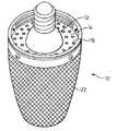
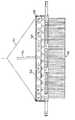
家庭用白熱電球用の置き換えとして使用するための本発明のLED証明器具の第1の実施形態は、図1〜5に示され、全体が数字10で示される。LEDバルブ10は、標準的なねじ込み式口金取付け器具に嵌合するねじ込み式口金インタフェース12を備える。ねじ込み式口金12は、後で述べるように、空気流がバルブ10を通るようにする開口16を含む放熱キャップ(thermal cap)14に固着される。 A first embodiment of the LED verification instrument of the present invention for use as a replacement for a domestic incandescent bulb is shown in FIGS. The
ねじ込み式口金12はまた、LEDバルブ・アレイに電力供給するのに使用される電力/制御電子部品を収容する。ねじ込み式口金12は、電力/制御回路20を収容する空洞18を有するフランジ付き形態である。つや消しアクリル拡散レンズ22は、LEDバルブ・アレイ23を覆い、放熱キャップ14に取り付けられる。The
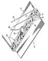
電気/熱コア・セクション24は、密度の非常に高いLEDアレイ26の相互接続を可能にする。コア24は、電気的相互接続、熱収集、およびLED26用の物理的支持を提供する。アレイ内で発生した熱は、制御された対流空気流によって、放熱キャップ14を通して散乱する。 The electrical /
図3〜5に示すように、第1の実施形態では、電気−熱コア24は、セグメント化された構造であり、分割構造は、コアを形成するために積重ねられた一連のディスクからなる。3つのディスク・タイプ、すなわち、回路ディスク28、金属ディスク30、および絶縁体ディスク32が存在する。全てのディスク・タイプは、高い熱コンダクタンスを有するように設計される。ディスクは、ディスク積重ね体(stack)の中心を通ってねじ込まれる保持ロッド34によって固定される。 As shown in FIGS. 3-5, in the first embodiment, the electro-
ディスクの表面は、熱伝達を最大にするために、ディスク間の熱抵抗を低減するように、機械加工され、合わされる。
回路ディスク28は、12個の30°セグメント36を有し、1つのセグメント38は、分割され、回路相互接続点の役をする。これは、各回路ディスク28が、直列に接続された12個のLEDバルブ26を有することを可能にする。4個の回路ディスク28が、直列に接続されて、48個のLEDバルブのLEDクラスタが提供される。光出力を増加するために、いくつかのLEDクラスタが、並列に接続される。通常、2〜6個のこうしたクラスタが並列に接続される。光の拡散を改善するために、LEDクラスタは、交互に配置され、互いに積重ねられない。金属ディスク30および絶縁ディスク32は、積重ね体内に適切に設置され、全ての合わせ面上に、放熱化合物(thermal compound)が使用される。積重ね体は、上記絶縁保持ロッド34によって一緒にねじ込まれ、放熱キャップ14に取り付けられる。キャップ14は、いくつかの機能を果たし、重要な設計要素の1つである。The surfaces of the disks are machined and mated to reduce the thermal resistance between the disks in order to maximize heat transfer.
構築されたコアは、その後、放熱キャップに熱的に、かつ、機械的に固定され、それにより、放熱回路(thermal circuit)が完成する。
LEDアレイからの光についての発光スペクトルおよび分布は、LEDのタイプと光路とによるものである。好ましくは、CRIが85+の白色光を生成するのに、2つのタイプの5mmLEDが利用される。The constructed core is then thermally and mechanically secured to the heat dissipating cap, thereby completing the heat dissipating circuit.
The emission spectrum and distribution for the light from the LED array depends on the type of LED and the light path. Preferably, two types of 5 mm LEDs are utilized to generate white light with a CRI of 85+.
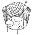
コアは、つや消しされた拡散器によって覆われ、かつ、収容され、つや消しされた拡散器は、光分布および空気流の制御という2つの主要な機能を有する。個々のLEDからの光は、つや消しされた拡散器レンズを使用してまとめられ、散乱させられ、それにより、光が全方向に均等に分布させられる。つや消しされた拡散器レンズの空洞は、放熱キャップに取り付けられると、ベンチュリ管を作る。冷たい空気は、入口に入り、一貫した一様な乱流を作る任意選択の羽根車を通じて流れ、ベンチュリ管を通って、空気流の流量が増加し、それにより、コア温度が低減される。熱い空気は、その後、ベンチュリ管の出口を通ってポート制御され、空気流の経路が終了する。 The core is covered and housed by a frosted diffuser, and the frosted diffuser has two main functions: light distribution and air flow control. The light from the individual LEDs is grouped and scattered using a frosted diffuser lens, thereby distributing the light evenly in all directions. The frosted diffuser lens cavity, when attached to the heat dissipation cap, creates a venturi tube. Cold air enters the inlet and flows through an optional impeller that creates a consistent and uniform turbulent flow, through the venturi, increasing the air flow rate, thereby reducing the core temperature. The hot air is then ported through the venturi exit and the air flow path is terminated.
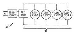
電力/制御セクション20は、LEDバルブ・アレイ24に対して電力を供給し制御し、広い範囲の周囲温度下で最適な光出力を確保すると共に、LED26の寿命を最大にすることができる。図6に示すように、電力/制御セクション20は、リニア電流レギュレーションおよび光学チョークを有するリニアDC電源によって整流およびフィルタリングを提供する。電力/制御セクション20は、「オプティック・バラスト」と呼ばれる独特の技術を利用する。 The power /
従来のLED電力コントローラは、LEDバルブ・アレイに直列に設置された種々のスイッチング回路による。スイッチング・レートおよび継続時間は、有効電力、したがって、発生する熱を制御する。これらの従来の配置構成に対する一部の欠点は、RFI/EMI−他の電子デバイスとの干渉を引き起こすライン汚染(line contamination)、部品数が多いことに伴う回路の複雑さ、効率および回路寿命を減らすコントローラ回路によって発生するさらなる熱、およびストローブ効果(strobe effect)を含む。 Conventional LED power controllers rely on various switching circuits installed in series with the LED bulb array. The switching rate and duration control the active power and thus the heat generated. Some drawbacks to these conventional arrangements are that RFI / EMI—line contamination that causes interference with other electronic devices, circuit complexity, efficiency and circuit life associated with high component count. Includes additional heat generated by the controller circuit to reduce, and the strobe effect.
オプティカル・バラスト技術は、電力制御のモノリシック手法に基づく非スイッチングリニアデザインを利用することによって、上記欠点をなくし、それによって、負荷(LEDアレイ)が、電力制御システムの一部になる。コントローラの外部部分は、低電圧(VLV)デザインであり、アレイによって要求される全エネルギーの約2%だけを消費する。アレイについて要求される電力の残りは、アレイに捕捉され、LEDは、一定範囲の電力によって動作するように強制される。電力範囲が一定であるため、外部コントローラではなく、LEDの動的抵抗が電力コンローラになる。そのため、アレイについて要求される電力は、アレイを制御するのに必要とされる電力を含み、電力は全て、光を生成するのに使用される。アレイをこうして制御することによって、アレイの効率は、ほぼ100%である。それは、電力が全て、光を生成し、生成される熱が、光を生成する結果であり、制御回路において発生しないからである。結果として、アレイを制御するのに必要とされる電力は、全光出力の一部分であることになる。したがって、用語「オプティック・バラスト」の状態となる。電力/制御セクションの好ましい実施形態のさらなる詳細が以下に述べられる。 Optical ballast technology eliminates the above disadvantages by utilizing a non-switching linear design based on a monolithic approach to power control, whereby the load (LED array) becomes part of the power control system. The external part of the controller is a low voltage (VLV) design, consuming only about 2% of the total energy required by the array. The rest of the power required for the array is captured in the array and the LEDs are forced to operate with a range of power. Since the power range is constant, the dynamic resistance of the LED, not the external controller, becomes the power controller. As such, the power required for the array includes the power required to control the array, and all the power is used to generate light. By controlling the array in this way, the efficiency of the array is almost 100%. That is because all the power generates light and the heat generated is the result of generating light and not generated in the control circuit. As a result, the power required to control the array will be part of the total light output. Therefore, the term “optic ballast” results. Further details of preferred embodiments of the power / control section are described below.
4個のLEDクラスタまたは192個のLEDを含む、図1〜6に示す白熱電球(bulb)用のプロトタイプの置き換えが、60ワット白熱電球と等価の光を生成し、一方、約20ワットすなわち60ワット白熱電球の1/3の電力を消費し、約66%の電力節約をもたらすことがわかった。バルブの動作温度は、摂氏51.7°(華氏125°)であり、60ワット電球より35°低かった。LEDバルブの予想平均寿命は、連続使用において20年+である。 Replacing the prototype for the incandescent bulb shown in FIGS. 1-6, including four LED clusters or 192 LEDs, produces light equivalent to a 60 watt incandescent bulb, while approximately 20 watts or 60 It has been found that it consumes 1/3 the power of a watt incandescent bulb, resulting in about 66% power savings. The operating temperature of the bulb was 51.7 degrees Celsius (125 degrees Fahrenheit), 35 degrees lower than the 60 watt bulb. The expected average life of the LED bulb is 20 years + in continuous use.
先に述べた第1の好ましい実施形態では、LEDバルブ10は、既存の120ボルトの白熱電球を置き換えるように設計される。インタフェースを変更することにより、バルブは、他のタイプの照明器具において、ならびに、他の用途に使用されてもよい。In the first preferred embodiment described above, the
たとえば、上述した本発明のLEDバルブは、蛍光灯などの他のタイプの光源を置き換えるのに使用されてもよい。既存の蛍光照明器具に類似のレイ・イン・パネル(lay in panel)は、ねじ込み式口金用のいくつかのレセプタクルを備えてもよい。一般に、4〜8個のいずれかのこうしたレセプタクルは、所望の光出力に応じて設けられる。レセプタクルは、電源からの電気ワイヤへ接続するために、ジャンクション・ボックスに配線される。 For example, the LED bulb of the present invention described above may be used to replace other types of light sources such as fluorescent lamps. A lay in panel, similar to existing fluorescent luminaires, may be equipped with several receptacles for screw caps. In general, any of 4-8 such receptacles are provided depending on the desired light output. The receptacle is wired to a junction box for connection to electrical wires from the power source.
あるいは、図7に示すように、既存の蛍光レイ・イン・パネルを置き換えるために、置き換えレイ・イン・パネル50が設けられてもよい。パネル50は、LEDバルブ54を含む凹所52を備える。インタフェースは、従来の方法で配線に対する直接接続を可能にするジャンクション・ボックス56である。電力/制御回路は、ジャンクション・ボックス56内に含まれてもよく、電力/制御セクションの出力ワイヤ58は、LEDアレイ用のコネクタにつながってもよい。つや消しされた拡散器パネル60が、設けられて、LEDアレイからの光が、まとめられ、散乱させられ、それにより、光が全方向に均等に分布させられる。Alternatively, as shown in FIG. 7, a replacement ray-in panel 50 may be provided to replace an existing fluorescent ray-in panel. The panel 50 includes a
本発明のLEDバルブ68の第2の実施形態は、典型的なコブラ・ヘッド街路灯ヘッド70内で街路灯として使用するために、図8に示される。電球68は、灯器ヘッド(light head)70に電球68を接続することを可能にするねじ込み式口金インタフェース72を備える。第1の実施形態と同様に、電力/制御セクション74は、ねじ込み式口金72内に含まれる。電気/熱コアおよびLEDアレイは、コブラ・ヘッドの一番上に搭載され、ねじ込み式口金72内で、電力/制御セクション74にワイヤ75によって接続される。電気/熱コア76は、第1の実施形態と同様に配列された密度の高いLEDアレイ78を含む。LED78は、各クラスタ内の48個のLEDの8個のクラスタで配列される。コアは、第1の実施形態と同様に、回路ディスク、金属ディスク、および絶縁体ディスクで構築される。コブラ・ヘッド70が、拡散器カバー80を備えるため、LEDバルブ68用の別個の拡散器は必要とされない。 A second embodiment of the
蛍光照明器具の置き換えで使用するための、本発明のLED照明器具の第3の実施形態は、図9〜14に示され、全体が参照数字110で示される。図に示すLED照明器具110は、天井112から懸垂保持されるようになっている。図に示すような搭載ブラケット114は、電気アウトレット・ボックス116を通じて天井112に取り付けられる。LED照明器具110は、適した懸垂保持ガイ・ワイヤ118によってブラケット114から懸垂保持され、ワイヤ120によって電気ボックス116に接続される。ワイヤ120は、次に、LEDアレイ・アセンブリ124に対して電力を供給し制御する電力制御回路を含む制御ボックス122に接続される。その詳細は、以下でさらに述べられるであろう。LEDアレイ124からの光は、拡散器システム126を通過して、照明器具からの、均等で、かつ、一様な光出力が実現される。 A third embodiment of the LED luminaire of the present invention for use in replacing a fluorescent luminaire is shown in FIGS. 9-14 and generally indicated by
この実施形態の光コンポーネントの詳細は、図12〜14に詳細に示される。図示する実施形態は、チップ・ベースLEDアレイ128を利用する。これらのチップは、各チップ当たり約42個のLEDを備え、図に示す光は、一面当たり14個のチップを利用する。LED灯アレイは、LED128の2つの平行列を利用し、各列は、制御セクションによって独立に給電され、制御される。LEDチップ128は、LED128によって発生する熱が、大気内に散乱することを可能にする熱コア・ヒート・シンク130上に搭載される。図示する実施形態で利用されるヒート・シンク130のバージョンは、LEDチップ128が取り付けられた先の金属管130である。中空金属管130は、金属管130の上部および側面に沿って開口132を備えて、熱散乱を補助するように、空気流が管130を流れることが可能になる。LEDチップ128が搭載先の管130の外側の、管134のさらなる対は、他の光学コンポーネントの取付けを可能にするために設けられる。これらの管134はまた、穴136を備え、穴136は、ヒート・シンク130の管内の穴132と整列して、図14で詳細に示すように、適切な空気流を可能にする。 Details of the optical components of this embodiment are shown in detail in FIGS. The illustrated embodiment utilizes a chip-based
図9〜14に示す照明器具110では、LED128からの光は、下方に送られて、プリズム138に入り、プリズム138は、光を拡散器システム126に入るように反射する。図示する実施形態では、拡散器システム126は、導波路であり、導波路は、導波路の全表面に沿って、LED128からの光の拡散を可能にする。プリズム138は、搭載管140によって所定場所に保持され、全体アセンブリは、クロス・ブリッジ142によって接続される。図示する実施形態では、クロス・ブリッジ142は、照明器具に対して美学的に好ましい外観を提供するために、プリズムの長さを持つ。全体アセンブリは、ボルト144を使用して一緒にボルト止めされる。 In the
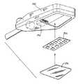
本発明のLED照明器具の第4の実施形態は、図15に示され、全体が参照数字200で示される。この照明器具は、ハウジング214内に搭載されたLEDアレイ212を備える。拡散器216は、ハウジング214に取り付け、ハウジング214内にコンポーネントを保持するために設けられる。LEDアレイ212を拡散器216から離間させるために、スペーサ・ストリップ218が設けられ、スペーサ・ストリップ218は、LEDアレイ212の冷却用の空気流を可能にする。LEDは、ワイヤ222によって電源に接続された電力/制御コンポーネント220によって電力供給される。図15に示す本発明の実施形態は、ストリップ照明または単一蛍光管を有する照明器具の置き換えに特に役立つ。 A fourth embodiment of the LED lighting fixture of the present invention is shown in FIG. The luminaire includes an
本発明のLED照明器具のこの実施形態は、温室および他のこうした用途で使用するための栽培バルブ(grow bulb)について特に有用である。これらの栽培バルブは、通常、400〜525nm、610〜720nmの波長範囲内の光である光合成有効放射(photosynthetic active radiation)(PAR)を提供する。これらの波長は、所望の波長で光を放出する、適した赤および青LEDを利用することによって、本発明の照明器具で複製することができる。 This embodiment of the LED lighting fixture of the present invention is particularly useful for grow bulbs for use in greenhouses and other such applications. These cultivated bulbs typically provide photosynthetic active radiation (PAR), which is light within the wavelength range of 400-525 nm, 610-720 nm. These wavelengths can be replicated with the luminaire of the present invention by utilizing suitable red and blue LEDs that emit light at the desired wavelength.
本発明のLED照明器具の第5の実施形態は、図16に示される。この実施形態は、典型的なコブラ・ヘッド街路灯ヘッド250内で街路灯として使用するためのものである。コブラ・ヘッドは、制御回路252およびコブラ・ヘッド内に搭載するためのLED灯アレイ254を備える。拡散器パネル256は、LEDアレイによって発生した光を拡散するために設けられる。 A fifth embodiment of the LED lighting fixture of the present invention is shown in FIG. This embodiment is for use as a street light in a typical Cobra Head
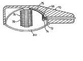
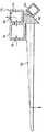
白熱電球を置き換えるときに使用するための、本発明による照明器具の第6の実施形態は、図17および図18に示され、全体が参照数字310で示される。LEDバルブ310は、標準的なねじ込み式口金取付け器具に嵌合するねじ込み式口金インタフェース312を備える。灯器バルブ310は、LED灯アレイ314および電力制御セクションを通して電源に接続されたヒート・シンク316を備える。LED灯アレイ314およびヒート・シンク316は、ねじ込み式口金取付け器具312の空洞内に含まれる。LED灯アレイ314の上には、光学拡散器320がかぶさり、光学拡散器320は、光の他の部分を横にそらしながら、LED灯アレイ314からの光の一部が、光学拡散器320を真っ直ぐに通過することを可能にして、照明器具310によって照明される空間の全体的に良好な照明を実現する。 A sixth embodiment of a luminaire according to the present invention for use when replacing incandescent bulbs is shown in FIGS. 17 and 18 and generally indicated by
白熱電球を置き換えるときに使用するための、本発明による照明器具のこの実施形態の変形は、図19に示され、全体が参照数字410で示される。LEDバルブ410は、標準的なねじ込み式口金取付け器具に嵌合するねじ込み式口金インタフェース412を備える。バルブ410は、制御回路を含む回路板に取り付けられた、複数の個々のLED416からなるLED灯アレイ414を備える。セラミック挿入物418は、LEDアレイ用のヒート・シンクの役目を果たすために設けられる。LED灯アレイの上には、円筒導波路レンズ・ハウジング420がかぶさり、円筒導波路レンズ・ハウジング420は、光の他の部分を横にそらしながら、LED灯アレイ314からの光の一部が、円筒導波路レンズ・ハウジング420を真っ直ぐに通過することを可能にして、照明器具410によって照明される空間の全体的に良好な照明を実現する。A variation of this embodiment of a luminaire according to the present invention for use when replacing incandescent bulbs is shown in FIG. 19 and generally indicated by
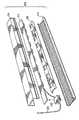
蛍光照明器具の置き換えで使用するための、本発明のLED照明器具の第7の実施形態は、図20〜23に示され、全体が参照数字510で示される。図に示すLED照明器具510は、天井から懸垂保持されるようになっている。搭載ブラケットは、電気アウトレット・ボックスを通じて天井に取り付けられる。照明器具510は、適した懸垂保持ガイ・ワイヤ512の使用によってブラケットから懸垂保持され、ワイヤ514によって電気ボックスに接続される。ワイヤ514は、次に、LEDアレイ・アセンブリ516に対して電力を供給する電源に接続される。その詳細は、以下でさらに述べられるであろう。LEDアレイ516からの光は、拡散器システム518を通過して、照明器具510からの、均等で、かつ、一様な光出力が実現される。 A seventh embodiment of the LED luminaire of the present invention for use in replacing a fluorescent luminaire is shown in FIGS. 20-23 and is generally designated by the
この実施形態の光コンポーネントの詳細は、図21および図22に示される。図示する実施形態は、チップ・ベースLEDアレイ520を利用する。これらのチップ520は、各チップ当たり約42個のLEDを備え、図に示す光は、一面当たり14個のチップを利用する。LED灯アレイは、LEDチップ520の2つの平行列を利用し、各列は、電源によって独立に給電され、制御コントローラによって制御される。LEDチップ520は、LEDチップ520によって発生する熱が、大気内に散乱することを可能にする熱コア・ヒート・シンク522上に搭載される。図示する実施形態で利用されるヒート・シンク522のバージョンは、LEDチップ520が取り付けられた先の金属管522である。中空金属管522は、金属管522の上部および側面に沿って開口524を備えて、熱散乱を補助するように、空気流が管522を流れることが可能になる。管522は、光拡散器アセンブリ518が取り付けられる先のケーシング526内に含まれる。ケーシング526は、穴530のラビリンス配置構成を備え、それによって、図21で詳細に示すように、埃の侵入を最小にしながら、適切な空気流を可能にする。Details of the optical component of this embodiment are shown in FIGS. The illustrated embodiment utilizes a chip-based
図20〜23に示す照明器具510では、LEDアレイ520からの光は、光を拡散器システム518に入るように下方に送られる。図示する実施形態では、拡散器システム518は、複合導波路であり、複合導波路は、導波路の全表面に沿って、LEDアレイ520からの光の拡散を可能にする。複合導波路は、2つのタイプの個々の要素534および536からなり、要素534および536は、交互に積重ねられて、導波路光拡散器518が形成される。 In the
要素534は、全体が半円形状538を有し、翼部540が、要素534の一番上で両側に延びる。翼部540は、個々の要素が、Uチャネル542内で保持されることを可能にし、Uチャネル542は、次に、ケーシング526に接続される。要素534は、半円形状538の露出した表面544に沿ってLEDアレイ520からの光が全体的に拡散することを可能にする。要素534の上部表面546は、LEDアレイ520からの光が、要素534の内部に入ることを可能にする。
要素536は、半円形状548であり、三角形切り欠き部550は、半円形状548の底部から上に延び、翼部540は、要素536の一番上で要素の両側に延びて、Uチャネル542内で保持される。三角形切り欠き部550の角度は、要素536内で、LEDアレイ520からの光の全内部反射を可能にするように選択される。全内部反射は、光作用を提供するように、要素536の露出表面で光が観測されることを可能にする。
要素534および536は、外側に延びる半円端部部品552によってUチャネル542内で保持され、さらなる光投射を行うために、光透過性がある。
上述したように、本発明のLED照明器具は、制御システムにおいてLEDアレイをバラストとして利用する。好ましくは、制御システムは、アクティブ・ブートストラップ回路であり、LEDアレイの動的抵抗が、ブートストラップとして使用される。こうして、LEDアレイは、アクティブ・ブートストラップ回路と組み合わせて、LEDアレイによって使用される電力を制御し、広い範囲の周囲温度下で最適な光出力を確保すると共に、LEDの寿命を最大にする。好ましい実施形態のアクティブ・ブートストラップ回路のブロック図は、図24に示される。好ましくは、本発明のLED照明器具は、北米では一般的であるように、120ボルトACなどの標準的な家庭用電源に接続されるが、他の電源も使用可能である。電源を利用して、120ボルトACが、照明器具で利用されるLEDアレイのサイズについて、所望のレベルのDC電圧に変換される。電源の出力は、LEDアレイに直接送られる。LEDアレイは、電圧からアクティブ・ブートストラップ回路によって使用される小さなブートストラップ電圧を引いた電圧全てを降下させるように構成される。そのため、168DCボルトのリニア出力および5DCボルトを使用するブートストラップ回路の場合、LEDアレイは、163DCボルトを使用するように設計される。こうして、ほとんどの電力が、LEDアレイによって使用される。 As described above, the LED lighting apparatus of the present invention uses the LED array as a ballast in the control system. Preferably, the control system is an active bootstrap circuit and the dynamic resistance of the LED array is used as the bootstrap. Thus, the LED array, in combination with an active bootstrap circuit, controls the power used by the LED array, ensuring optimal light output under a wide range of ambient temperatures and maximizing LED lifetime. A block diagram of the active bootstrap circuit of the preferred embodiment is shown in FIG. Preferably, the LED luminaire of the present invention is connected to a standard household power source, such as 120 volt AC, as is common in North America, although other power sources can be used. Using the power supply, 120 volts AC is converted to a desired level of DC voltage for the size of the LED array utilized in the luminaire. The output of the power supply is sent directly to the LED array. The LED array is configured to drop all of the voltage minus the small bootstrap voltage used by the active bootstrap circuit. Thus, for a bootstrap circuit that uses a linear output of 168 DC volts and 5 DC volts, the LED array is designed to use 163 DC volts. Thus, most of the power is used by the LED array.
LEDアレイは熱的にマッピングされ、動的抵抗範囲が得られる。ブートストラップ回路は、LEDアレイに接続され、LEDアレイの下側からブートストラップ電圧を得る。LEDアレイの動的抵抗は、回路によってブートストラップ源として使用される。ブートストラップ回路は、非常に低い内部電力要件を有し、電力の98%以上が、光を生成するために、LEDアレイによって使用される。 The LED array is thermally mapped to obtain a dynamic resistance range. The bootstrap circuit is connected to the LED array and obtains a bootstrap voltage from the lower side of the LED array. The dynamic resistance of the LED array is used by the circuit as a bootstrap source. Bootstrap circuits have very low internal power requirements, and over 98% of the power is used by the LED array to generate light.
アクティブ・ブートストラップ回路は、ブートストラップ電圧を調節する電圧レギュレータVregを含み、ブートストラップ電圧は、Vrefに提供され、電流レギュレータIregに対して、プログラムされた所定の一定レベルの基準電圧を設定するのに使用される。所定の電圧は、LEDアレイの電力範囲および範囲窓サイズに基づいて選択される。所定の電圧は、好ましくは、LEDアレイの電力範囲の中心になるように選択される。 The active bootstrap circuit includes a voltage regulator Vreg that adjusts the bootstrap voltage, which is provided to Vref and sets a programmed predetermined constant level reference voltage for the current regulator Ireg. Used for. The predetermined voltage is selected based on the power range and range window size of the LED array. The predetermined voltage is preferably selected to be at the center of the power range of the LED array.
ブートストラップ回路はまた、LEDアレイから、効率が最大の光出力を実現するために、LEDアレイに流れる電流を調節する電流レギュレータを含む。アレイ内の電流は、Isensによって検知され、Isensは、電流レギュレータIregに対する制御信号出力を提供するようにプログラムされる。Isensの出力は、LEDアレイの電力範囲を参照してプログラムされ、アレイの安全動作範囲の中心に設定される。ブートストラップ範囲は、非常に狭く、はっきりとは検出できない光出力の非常に小さな変化を反映するだけであり、LEDアレイによって消費される電力の98%以上が、光を生成するために使用されることが確実になる。 The bootstrap circuit also includes a current regulator that regulates the current flowing through the LED array in order to achieve the most efficient light output from the LED array. The current in the array is sensed by Isens, which is programmed to provide a control signal output for the current regulator Ireg. The output of Isens is programmed with reference to the power range of the LED array and is set to the center of the safe operating range of the array. The bootstrap range is very narrow and only reflects very small changes in light output that are not clearly detectable, and more than 98% of the power consumed by the LED array is used to generate light. That will be certain.
Isensからの検知された電流信号は、Vrefからの所定の基準電圧と共に、電流レギュレータIregに送られて、電流、したがって、LEDアレイの電力が制御される。アレイの抵抗の変化の結果として、または、電源電圧の雑音によって、Isensからの検知された電流が所望の値からドリフトする場合、Iregは、アレイ内に流れる電流を能動的に調整して、検知された値を補償し、検知された値を所望レベルに戻す。調整のための応答時間は、瞬時であり、したがって、電力コントローラは、LEDアレイの電力レベルの任意の変動を即座に相殺することができる。これは、電源またはアレイ内で発生する雑音が、即座に相殺されるため、さらに高い電力効率およびフリッカの無い光出力をもたらす。検知された電流および基準電圧のこれらのフィードバック・ループを利用することによって、LEDアレイの動的抵抗の変化は、能動的に、検出され、調整され、最適化されて、最高の電力効率および光出力が得られる。そのため、本発明の回路は、周囲温度の上昇か、LEDアレイによって発生する熱のいずれかによる温度上昇に伴って、LEDの電気的特性が変化するにつれて、LEDアレイが熱暴走する従来技術の問題を克服する。 The sensed current signal from Isens is sent to the current regulator Ireg along with a predetermined reference voltage from Vref to control the current and thus the power of the LED array. If the sensed current from Isens drifts from the desired value as a result of a change in the resistance of the array or due to noise in the supply voltage, Ireg actively adjusts the current flowing in the array to sense Compensate the sensed value and return the sensed value to the desired level. The response time for adjustment is instantaneous, so the power controller can immediately cancel any fluctuations in the power level of the LED array. This results in higher power efficiency and flicker-free light output because noise generated within the power supply or array is immediately canceled. By utilizing these feedback loops of sensed current and reference voltage, LED array dynamic resistance changes are actively detected, tuned and optimized to achieve the highest power efficiency and light. Output is obtained. Therefore, the circuit of the present invention is a problem of the prior art in which the LED array undergoes thermal runaway as the electrical characteristics of the LED change with increasing temperature due to either increased ambient temperature or heat generated by the LED array. Overcome.
本発明は、照明器具が使用されるタスク用の、適した強度と色の光を生成することができるLED照明器具を実現する。たとえば、第3の実施形態によるLED照明器具は、適切なLEDを選択することによって、40ワット蛍光照明器具の照明と等価の照明を生成することになり、一方で、大幅に少ない電力を利用し、一方で、LEDの平均寿命が連続使用状態で20プラス年であるため、交換と交換との間の寿命を延ばすことが実現される。第6の実施形態の照明器具は、地下鉄の、あるセクションが電力供給されていることを指示するために、ならびに、軌道に沿う列車の移動を制御するためのブロック制御のため、したがって、軌道の、あるセクションが電力供給されているかどうかを指示するために、地下鉄で使用されるような、特に、インジケータ・システム内で、典型的な白熱バルブの置き換えに利用することができる。インジケータ・バルブは、一般に、青であり、一方、列車制御照明の場合、典型的な、赤色灯、黄色灯、および緑色灯は、適切なLEDの選択によって利用され、これらのインジケータ灯は、容易に置き換えられる。第6の実施形態のデザインによって、5ワットを引き出すLEDが、60ワット電球と同じ光出力を生成し、一方で、90%の電気的節約を達成すると共に、バルブが、典型的な白熱バルブほどの頻度で交換される必要がないため、保守コストを大幅に低減することがわかった。この実施形態の灯器はまた、リセッタブル・ヒューズと共に利用されてもよく、LEDの一部が、焼損する場合などに、ヒューズは、開き、その後、数秒後に閉じ、したがって、点滅するバルブが、不良LED、および、バルブが交換を必要とすることを指示する。 The present invention provides an LED luminaire that can generate light of suitable intensity and color for the task in which the luminaire is used. For example, an LED luminaire according to the third embodiment will produce illumination equivalent to that of a 40 watt fluorescent luminaire by selecting the appropriate LED, while utilizing significantly less power. On the other hand, since the average life of the LED is 20 plus years in continuous use, it is possible to extend the life between replacements. The luminaire of the sixth embodiment is for indicating that a section of the subway is powered, as well as for block control for controlling the movement of the train along the track, and therefore for the track. It can be used to replace a typical incandescent bulb, especially in an indicator system, such as used in a subway to indicate whether a section is powered. Indicator bulbs are generally blue, while in the case of train control lighting, typical red, yellow, and green lights are utilized by the selection of appropriate LEDs, and these indicator lights are easily Is replaced by With the design of the sixth embodiment, an LED that draws 5 watts produces the same light output as a 60 watt bulb, while achieving 90% electrical savings and the bulb is as much as a typical incandescent bulb. It has been found that the maintenance cost is greatly reduced because it does not need to be replaced frequently. The lamp of this embodiment may also be utilized with resettable fuses, such as when a portion of the LED burns out, the fuse opens and then closes after a few seconds, so the flashing bulb is defective Indicates that the LED and bulb need replacement.
本発明の種々の好ましい実施形態が、詳細に述べられたが、本発明の精神から逸脱することなく、好ましい実施形態に対して変形形態を作ってもよいことが、当業者によって理解されるであろう。 Although various preferred embodiments of the present invention have been described in detail, it will be understood by those skilled in the art that modifications may be made to the preferred embodiments without departing from the spirit of the invention. I will.
Claims (14)
Translated fromJapanese前記LEDアレイは、高い強度の組み合わせ式光源を形成するために、直列接続の十分な数のLED、および、前記低電圧電力制御セクションに電力供給する低電圧電源を生成する電圧逓減デバイスを有し、
前記LEDアレイは動的抵抗を有し、前記低電圧電力制御セクションは、前記LEDアレイの低圧側に接続されるアクティブ・ブートストラップ回路を備え、前記アクティブ・ブートストラップ回路は、前記LEDアレイ内の電流を検知して、前記LEDアレイの動的抵抗によって生じる、所望のレベルからの変動を補償するように、前記LEDアレイの動的抵抗の関数として変わる前記検知された電流を前記LEDアレイを通る電流を調節する電流調節器手段に提供する手段を備える高電圧LED光源。A high voltage LED light source comprising an LED array, the LED array connected in series to a low voltage power control section for current regulation through the LED array;
The LED array has a sufficient number of LEDs connected in series to form a high intensity combined light source and a voltage grading device that generates a low voltage power supply that powers the low voltage power control section. ,
The LED array has a dynamic resistance, and thelow voltage power control section comprises an active bootstrap circuit connected to the low voltage side of the LED array, the active bootstrap circuit in the LED array The sensed current that changes as a function of the dynamic resistance of the LED array is passed through the LED array to sense current and compensate for variations from a desired level caused by the dynamic resistance of the LED array. A high voltage LED light sourcecomprising means for providing current regulator means for regulating current .
Applications Claiming Priority (5)
| Application Number | Priority Date | Filing Date | Title |
|---|---|---|---|
| CA2,478,001 | 2004-08-18 | ||
| CA002478001ACA2478001A1 (en) | 2004-08-18 | 2004-08-18 | Led light bulb |
| CA2,507,081 | 2005-05-11 | ||
| CA002507081ACA2507081A1 (en) | 2005-05-11 | 2005-05-11 | Led light |
| PCT/CA2005/001255WO2006017930A1 (en) | 2004-08-18 | 2005-08-18 | Led control utilizing dynamic resistance of leds |
Publications (2)
| Publication Number | Publication Date |
|---|---|
| JP2008510283A JP2008510283A (en) | 2008-04-03 |
| JP4989472B2true JP4989472B2 (en) | 2012-08-01 |
Family
ID=35907195
Family Applications (1)
| Application Number | Title | Priority Date | Filing Date |
|---|---|---|---|
| JP2007526149AExpired - Fee RelatedJP4989472B2 (en) | 2004-08-18 | 2005-08-18 | LED control using dynamic resistance of LED |
Country Status (5)
| Country | Link |
|---|---|
| US (1) | US7712925B2 (en) |
| EP (1) | EP1785011A4 (en) |
| JP (1) | JP4989472B2 (en) |
| AU (1) | AU2005274629B2 (en) |
| WO (1) | WO2006017930A1 (en) |
Families Citing this family (49)
| Publication number | Priority date | Publication date | Assignee | Title |
|---|---|---|---|---|
| WO2007008801A2 (en) | 2005-07-12 | 2007-01-18 | Spirit Acoustics Inc. | Acoustic systems for lighting in suspended ceilings |
| CN101595342B (en)* | 2006-10-23 | 2012-10-24 | 科锐公司 | Lighting device and installation method of light engine housing and/or decoration in lighting device |
| EP2088835A4 (en)* | 2006-10-24 | 2009-11-18 | Momo Alliance Co Ltd | Illumination device |
| US7686476B2 (en)* | 2007-07-26 | 2010-03-30 | Dl Manufacturing | LED dock light |
| CN101836042B (en) | 2007-09-21 | 2014-11-05 | 库帕技术公司 | Light emitting diode recessed light fixture |
| WO2009048951A2 (en)* | 2007-10-09 | 2009-04-16 | Philips Solid-State Lighting Solutions | Methods and apparatus for controlling respective load currents of multiple series-connected loads |
| US8322881B1 (en) | 2007-12-21 | 2012-12-04 | Appalachian Lighting Systems, Inc. | Lighting fixture |
| WO2010041044A2 (en)* | 2008-10-10 | 2010-04-15 | Carbon Innovation Technology Limited | Method of operating an led |
| US20100090576A1 (en) | 2008-10-14 | 2010-04-15 | Juang Der Ming | Omnidirectional light bulb using light emitting diode |
| US20100097798A1 (en)* | 2008-10-22 | 2010-04-22 | Caltraco International Limited | LED light module for portable lighting |
| US20100308731A1 (en)* | 2009-06-03 | 2010-12-09 | Anthony Mo | Light Engine |
| JP2011009064A (en)* | 2009-06-25 | 2011-01-13 | Aiko Giken Co Ltd | Base separation type led illumination fixture for road illumination lamp |
| FR2947852B1 (en)* | 2009-07-10 | 2014-08-22 | Elyssa | HOUSING FOR COMBINING AND ORIENTING SHEATHES, PIPES, CABLES IN A FLOORED CHAPE |
| US8596825B2 (en)* | 2009-08-04 | 2013-12-03 | 3M Innovative Properties Company | Solid state light with optical guide and integrated thermal guide |
| US8466628B2 (en)* | 2009-10-07 | 2013-06-18 | Lutron Electronics Co., Inc. | Closed-loop load control circuit having a wide output range |
| US8540402B2 (en) | 2010-05-23 | 2013-09-24 | RAB Lighting Inc. | LED housing with heat transfer sink |
| US8905589B2 (en) | 2011-01-12 | 2014-12-09 | Kenall Manufacturing Company | LED luminaire thermal management system |
| US9752769B2 (en) | 2011-01-12 | 2017-09-05 | Kenall Manufacturing Company | LED luminaire tertiary optic system |
| US20130294082A1 (en)* | 2011-01-18 | 2013-11-07 | Panasonic Corporation | Light bulb shaped lamp and lighting apparatus |
| US9010956B1 (en) | 2011-03-15 | 2015-04-21 | Cooper Technologies Company | LED module with on-board reflector-baffle-trim ring |
| US8680787B2 (en) | 2011-03-15 | 2014-03-25 | Lutron Electronics Co., Inc. | Load control device for a light-emitting diode light source |
| WO2012142447A1 (en)* | 2011-04-13 | 2012-10-18 | Amerlux, Llc | Directionally controllable street lamp |
| ITVI20110098A1 (en)* | 2011-04-18 | 2012-10-19 | Beghelli Spa | LED LIGHTING DEVICE FOR PUBLIC OR PRIVATE LIGHTING SYSTEMS |
| EP2735211B1 (en) | 2011-07-20 | 2018-04-18 | Philips Lighting Holding B.V. | Light source comprising a led strip |
| JP2013026061A (en)* | 2011-07-22 | 2013-02-04 | Panasonic Corp | Lamp and lighting fixture |
| US20130039074A1 (en)* | 2011-08-08 | 2013-02-14 | Yi Ding | Led Luminaire with Convection Cooling |
| US8888320B2 (en)* | 2012-01-27 | 2014-11-18 | Hubbell Incorporated | Prismatic LED module for luminaire |
| US9151477B2 (en) | 2012-02-03 | 2015-10-06 | Cree, Inc. | Lighting device and method of installing light emitter |
| US9151457B2 (en) | 2012-02-03 | 2015-10-06 | Cree, Inc. | Lighting device and method of installing light emitter |
| US8939600B1 (en)* | 2012-02-14 | 2015-01-27 | Hunter Industries, Inc. | Landscape down light fixture configured for water drainage |
| US8878443B2 (en) | 2012-04-11 | 2014-11-04 | Osram Sylvania Inc. | Color correlated temperature correction for LED strings |
| KR101981717B1 (en)* | 2012-05-10 | 2019-05-24 | 엘지이노텍 주식회사 | Lighting device |
| US8974077B2 (en) | 2012-07-30 | 2015-03-10 | Ultravision Technologies, Llc | Heat sink for LED light source |
| US9171826B2 (en) | 2012-09-04 | 2015-10-27 | Micron Technology, Inc. | High voltage solid-state transducers and solid-state transducer arrays having electrical cross-connections and associated systems and methods |
| US9055634B2 (en) | 2013-04-17 | 2015-06-09 | Kevin McDermott | Light emitting diode lighting device |
| US9386654B2 (en) | 2013-05-31 | 2016-07-05 | Damien McDermott | Controlled function light emitting diode lighting device and method |
| US20140354169A1 (en)* | 2013-05-31 | 2014-12-04 | Kevin McDermott | Light emitting diode lighting device |
| US9195281B2 (en) | 2013-12-31 | 2015-11-24 | Ultravision Technologies, Llc | System and method for a modular multi-panel display |
| US12372219B2 (en)* | 2014-05-30 | 2025-07-29 | Cree Lighting Usa Llc | LED luminaire with a cavity, finned interior, and a curved outer wall extending from a surface on which the light source is mounted |
| US9541270B2 (en) | 2014-07-18 | 2017-01-10 | ETi Solid State Lighting Inc. | Integral LED light fixture |
| USD776326S1 (en) | 2015-12-28 | 2017-01-10 | ETi Solid State Lighting Inc. | LED light fixture |
| US10197252B2 (en) | 2016-01-29 | 2019-02-05 | Hunter Industries, Inc. | Light fixture with removable light cartridge |
| US20170307183A1 (en)* | 2016-04-26 | 2017-10-26 | Lighting Science Group Corporation | Lamp assembly with universal base |
| US10553137B2 (en)* | 2018-02-21 | 2020-02-04 | Plantronics, Inc. | Visual display having adjustable diffusion strength |
| CN109640451B (en)* | 2018-12-29 | 2024-03-29 | 广东晶科电子股份有限公司 | Automobile dynamic turn signal lamp circuit |
| US20230161127A1 (en)* | 2020-04-15 | 2023-05-25 | CommScope Connectivity Belgium BV | Device and method for sealing cables in telecommunications enclosures |
| US11384925B1 (en) | 2021-04-29 | 2022-07-12 | Hunter Industries, Inc. | Light fixture and mount with multiple adjustments |
| US12331907B2 (en) | 2023-07-10 | 2025-06-17 | Hunter Industries, Inc. | Light fixture with expanding collar |
| US12305848B1 (en)* | 2024-09-04 | 2025-05-20 | Merry Electronics (Shenzhen) Co., Ltd. | Microphone having light-emitting structure |
Family Cites Families (32)
| Publication number | Priority date | Publication date | Assignee | Title |
|---|---|---|---|---|
| US3787752A (en)* | 1972-07-28 | 1974-01-22 | Us Navy | Intensity control for light-emitting diode display |
| JPS556687A (en)* | 1978-06-29 | 1980-01-18 | Handotai Kenkyu Shinkokai | Traffic use display |
| US5025204A (en)* | 1990-01-05 | 1991-06-18 | Hewlett-Packard Company | Current mirror using resistor ratios in CMOS process |
| JPH0525751U (en)* | 1991-09-12 | 1993-04-02 | 昌弘 奥村 | Light source cap for light emitting diode |
| US5149191A (en)* | 1991-12-23 | 1992-09-22 | Ian Lewin | Combination louver/lens light fixture shield |
| US5655830A (en)* | 1993-12-01 | 1997-08-12 | General Signal Corporation | Lighting device |
| JP2605874Y2 (en)* | 1993-12-28 | 2000-08-21 | 日本信号株式会社 | Multi-chip LED |
| FR2763203B1 (en)* | 1997-05-09 | 1999-06-04 | Schneider Electric Sa | ELECTRICAL CIRCUIT FOR SUPPLYING A LIGHT EMITTING DIODE |
| JP2000131529A (en)* | 1998-10-28 | 2000-05-12 | Bridgestone Corp | Linear luminous body |
| US6414801B1 (en)* | 1999-01-14 | 2002-07-02 | Truck-Lite Co., Inc. | Catadioptric light emitting diode assembly |
| US6267492B1 (en)* | 1999-04-15 | 2001-07-31 | 3M Innovative Properties Company | Illumination device with side emitting light guide |
| DE19922176C2 (en)* | 1999-05-12 | 2001-11-15 | Osram Opto Semiconductors Gmbh | Surface-mounted LED multiple arrangement and its use in a lighting device |
| US6367949B1 (en)* | 1999-08-04 | 2002-04-09 | 911 Emergency Products, Inc. | Par 36 LED utility lamp |
| US6161910A (en)* | 1999-12-14 | 2000-12-19 | Aerospace Lighting Corporation | LED reading light |
| CA2312285C (en)* | 2000-06-15 | 2008-06-17 | Go Simon Sunatori | Disc-shaped light-emitting diode illumination device |
| US6614358B1 (en)* | 2000-08-29 | 2003-09-02 | Power Signal Technologies, Inc. | Solid state light with controlled light output |
| US6598998B2 (en)* | 2001-05-04 | 2003-07-29 | Lumileds Lighting, U.S., Llc | Side emitting light emitting device |
| US6871983B2 (en)* | 2001-10-25 | 2005-03-29 | Tir Systems Ltd. | Solid state continuous sealed clean room light fixture |
| JP2003163090A (en)* | 2001-11-26 | 2003-06-06 | Matsushita Electric Works Ltd | Lighting equipment |
| US6600274B1 (en)* | 2001-12-14 | 2003-07-29 | Dme Corporation | LED current regulation circuit for aircraft lighting system |
| US6851834B2 (en)* | 2001-12-21 | 2005-02-08 | Joseph A. Leysath | Light emitting diode lamp having parabolic reflector and diffuser |
| US6693394B1 (en)* | 2002-01-25 | 2004-02-17 | Yazaki North America, Inc. | Brightness compensation for LED lighting based on ambient temperature |
| US6933707B2 (en)* | 2002-06-27 | 2005-08-23 | Luxidein Limited | FET current regulation of LEDs |
| US6860628B2 (en)* | 2002-07-17 | 2005-03-01 | Jonas J. Robertson | LED replacement for fluorescent lighting |
| US6787999B2 (en)* | 2002-10-03 | 2004-09-07 | Gelcore, Llc | LED-based modular lamp |
| JP4236894B2 (en)* | 2002-10-08 | 2009-03-11 | 株式会社小糸製作所 | Lighting circuit |
| US6853151B2 (en)* | 2002-11-19 | 2005-02-08 | Denovo Lighting, Llc | LED retrofit lamp |
| JP3498290B1 (en)* | 2002-12-19 | 2004-02-16 | 俊二 岸村 | White LED lighting device |
| JP2004206947A (en)* | 2002-12-24 | 2004-07-22 | Toyoda Gosei Co Ltd | Light emitting diode, lighting fixture and their process of manufacture |
| US6943640B2 (en)* | 2003-03-03 | 2005-09-13 | Lockhead Martin Corporation | Current source modulator |
| US6982518B2 (en)* | 2003-10-01 | 2006-01-03 | Enertron, Inc. | Methods and apparatus for an LED light |
| US7301288B2 (en)* | 2004-04-08 | 2007-11-27 | International Rectifier Corporation | LED buck regulator control IC |
- 2005
- 2005-08-18JPJP2007526149Apatent/JP4989472B2/ennot_activeExpired - Fee Related
- 2005-08-18EPEP05774835Apatent/EP1785011A4/ennot_activeCeased
- 2005-08-18USUS11/573,931patent/US7712925B2/ennot_activeExpired - Fee Related
- 2005-08-18AUAU2005274629Apatent/AU2005274629B2/ennot_activeCeased
- 2005-08-18WOPCT/CA2005/001255patent/WO2006017930A1/enactiveApplication Filing
Also Published As
| Publication number | Publication date |
|---|---|
| EP1785011A4 (en) | 2007-11-21 |
| WO2006017930A1 (en) | 2006-02-23 |
| WO2006017930A8 (en) | 2006-05-26 |
| US7712925B2 (en) | 2010-05-11 |
| AU2005274629A1 (en) | 2006-02-23 |
| US20080219001A1 (en) | 2008-09-11 |
| AU2005274629B2 (en) | 2011-06-09 |
| EP1785011A1 (en) | 2007-05-16 |
| JP2008510283A (en) | 2008-04-03 |
| HK1105509A1 (en) | 2008-02-15 |
Similar Documents
| Publication | Publication Date | Title |
|---|---|---|
| JP4989472B2 (en) | LED control using dynamic resistance of LED | |
| US7658510B2 (en) | System and method for power control in a LED luminaire | |
| US9217542B2 (en) | Heat sinks and lamp incorporating same | |
| CN102844619B (en) | There is the luminaire of radiating piece | |
| US7784969B2 (en) | LED based light engine | |
| KR101500977B1 (en) | LED-based facilities and associated methods for thermal management | |
| US9353916B2 (en) | Elongated LED luminaire and associated methods | |
| US20110156584A1 (en) | Led lighting device | |
| US20140293603A1 (en) | Led light bulb replacement with adjustable light distribution | |
| US7182496B2 (en) | Multiple LED focused lighting device | |
| CN104641173A (en) | Non-curved LED illuminant | |
| US8360622B2 (en) | LED light source in incandescent shaped light bulb | |
| RU2638821C2 (en) | Led lamp for street lighting | |
| CN101019467B (en) | LED control utilizing dynamic resistance of LEDs | |
| CN201555069U (en) | Efficient heat-dissipation type LED lamp | |
| KR20140076849A (en) | Lighting System for mirror | |
| US7264379B2 (en) | High bay lighting efficiency I | |
| TWM441798U (en) | LED lighting apparatus | |
| CA2575546C (en) | Led control utilizing dynamic resistance of leds | |
| CN201992367U (en) | Super-high-power light-emitting diode (LED) lighting lamp | |
| HK1105509B (en) | Led control utilizing dynamic resistance of leds | |
| RU237031U1 (en) | LED luminaire with active cooling | |
| RU2820024C1 (en) | Light-emitting diode lamp | |
| JP2013125603A (en) | Led lighting fixture | |
| CA2507081A1 (en) | Led light |
Legal Events
| Date | Code | Title | Description |
|---|---|---|---|
| A621 | Written request for application examination | Free format text:JAPANESE INTERMEDIATE CODE: A621 Effective date:20080808 | |
| A131 | Notification of reasons for refusal | Free format text:JAPANESE INTERMEDIATE CODE: A131 Effective date:20110207 | |
| A601 | Written request for extension of time | Free format text:JAPANESE INTERMEDIATE CODE: A601 Effective date:20110506 | |
| A602 | Written permission of extension of time | Free format text:JAPANESE INTERMEDIATE CODE: A602 Effective date:20110513 | |
| A521 | Request for written amendment filed | Free format text:JAPANESE INTERMEDIATE CODE: A523 Effective date:20110808 | |
| A131 | Notification of reasons for refusal | Free format text:JAPANESE INTERMEDIATE CODE: A131 Effective date:20110907 | |
| A601 | Written request for extension of time | Free format text:JAPANESE INTERMEDIATE CODE: A601 Effective date:20111207 | |
| A602 | Written permission of extension of time | Free format text:JAPANESE INTERMEDIATE CODE: A602 Effective date:20111214 | |
| TRDD | Decision of grant or rejection written | ||
| A01 | Written decision to grant a patent or to grant a registration (utility model) | Free format text:JAPANESE INTERMEDIATE CODE: A01 Effective date:20120402 | |
| A01 | Written decision to grant a patent or to grant a registration (utility model) | Free format text:JAPANESE INTERMEDIATE CODE: A01 | |
| A61 | First payment of annual fees (during grant procedure) | Free format text:JAPANESE INTERMEDIATE CODE: A61 Effective date:20120427 | |
| R150 | Certificate of patent or registration of utility model | Free format text:JAPANESE INTERMEDIATE CODE: R150 | |
| FPAY | Renewal fee payment (event date is renewal date of database) | Free format text:PAYMENT UNTIL: 20150511 Year of fee payment:3 | |
| LAPS | Cancellation because of no payment of annual fees |