JP4989196B2 - Vehicle display device - Google Patents
Vehicle display deviceDownload PDFInfo
- Publication number
- JP4989196B2 JP4989196B2JP2006316997AJP2006316997AJP4989196B2JP 4989196 B2JP4989196 B2JP 4989196B2JP 2006316997 AJP2006316997 AJP 2006316997AJP 2006316997 AJP2006316997 AJP 2006316997AJP 4989196 B2JP4989196 B2JP 4989196B2
- Authority
- JP
- Japan
- Prior art keywords
- dial
- decorative member
- light
- display device
- index
- Prior art date
- Legal status (The legal status is an assumption and is not a legal conclusion. Google has not performed a legal analysis and makes no representation as to the accuracy of the status listed.)
- Active
Links
- 239000000446fuelSubstances0.000description8
- 210000000078clawAnatomy0.000description6
- 238000005259measurementMethods0.000description6
- 230000003287optical effectEffects0.000description6
- 230000000007visual effectEffects0.000description6
- 238000005286illuminationMethods0.000description4
- 230000000694effectsEffects0.000description3
- 238000005034decorationMethods0.000description2
- 238000013461designMethods0.000description2
- 238000009792diffusion processMethods0.000description2
- 229920003002synthetic resinPolymers0.000description2
- 239000000057synthetic resinSubstances0.000description2
- XLYOFNOQVPJJNP-UHFFFAOYSA-NwaterSubstancesOXLYOFNOQVPJJNP-UHFFFAOYSA-N0.000description2
- 239000011521glassSubstances0.000description1
- 230000002452interceptive effectEffects0.000description1
- 238000000034methodMethods0.000description1
- 238000012986modificationMethods0.000description1
- 230000004048modificationEffects0.000description1
- 238000012545processingMethods0.000description1
Images


Landscapes
- Details Of Measuring Devices (AREA)
- Instrument Panels (AREA)
Description
Translated fromJapanese本発明は、車両用表示装置に関し、より詳細には、画定された表示領域内に複数の文字板を含み、それぞれ別々の測定値を表示する車両用表示装置に関するものである。 The present invention relates to a display device for a vehicle, and more particularly to a display device for a vehicle that includes a plurality of dials in a defined display area and displays different measurement values.
例えば図5に示される、車両の運転席に広く配設されている一般的なコンビネーションメータ1内には、速度計2、エンジン回転計3、燃料残量計4、水温計5等の計器が配設されている。 For example, in a general combination meter 1 widely shown in the driver's seat of the vehicle shown in FIG. 5, instruments such as a speedometer 2, an engine tachometer 3, a fuel remaining amount meter 4, and a
上述した各計器の大きさは、個々の重要度や、速度の常時表示を規定した法令、意匠上の見栄え等に応じて異なる場合があるが、いずれにしてもこれらの計器は、コンビネーションメータ1内にそれぞれ独立して配設されるのが通常である。 The size of each of the above-mentioned meters may vary depending on the importance of each item, the law that stipulates the constant display of speed, the appearance of the design, etc. In any case, these meters are the combination meter 1. Usually, they are arranged independently in each.
しかし、コンビネーションメータ1内の限られたスペースの中に各計器を独立してそれぞれ配設するには、文字板をある程度の大きさに制約する等の手当てを講じなければならない等の不具合があった。 However, in order to arrange each instrument independently in the limited space in the combination meter 1, there is a problem that measures such as restricting the dial to a certain size must be taken. It was.
そこで従来より、コンビネーションメータ内のスペースを有効活用するため、複数の計器を一体化し、一つの計器の表示領域で二つの計器の機能を果たす表示装置が提案されている。 Therefore, conventionally, in order to effectively use the space in the combination meter, a display device has been proposed in which a plurality of instruments are integrated and the function of two instruments is performed in the display area of one instrument.
その一つとして、指針軸を挟んで一直線上に長針および短針を延設し、指針軸から下半分の文字板部分を見返し板で隠すと共に、長針の指示位置に応じた目盛と短針の指示位置に応じた目盛とを上半分の文字板部分に同心円状に配置して、長針による指示値の指示と短針による指示値の指示とを選択して行わせる、本出願人が過去に出願したものがある(例えば特許文献1)。 As one of them, the long hand and the short hand are extended on a straight line across the pointer shaft, the lower half dial plate part is hidden from the pointer shaft by the turn-back plate, and the scale and short hand indicating position according to the indicating position of the long hand Applicants have applied for in the past to arrange the indication according to the condition of concentric circles on the upper half of the dial and select the indication value with the long hand and the indication value with the short hand. (For example, Patent Document 1).
他には、文字板の裏側に大小の円弧状ケースを取り付けて、各ケース内にそれぞれ配設したブロックを、モータ駆動のプーリによりケース内で周回される無端ベルトに取り付けて各ケース内でそれぞれスライドさせ、各ケースに沿って文字板にそれぞれ形成された円弧状のスリットから各ブロックの一部を露出させてポインタとし、各スリットの周縁の文字板部分に形成した目盛を各ブロックのポインタによりそれぞれ指示させるようにしたものがある(例えば特許文献2)。
上述したそれぞれの事例では、別々の測定値を指示する指標を近接して配置することで、コンビネーションメータ内のスペースを有効に活用することを実現している。しかし指標が近接配置されることで利用者がそれら指標を認識する際に混同を生じ、測定値を見誤るおそれがあるという問題がでてきた。 In each of the above-described cases, it is possible to effectively use the space in the combination meter by arranging the indicators indicating different measurement values close to each other. However, due to the proximity of the indicators, there is a problem that the user may confuse when recognizing the indicators, and the measurement value may be mistaken.
また、上記問題を解決するため、近接配置されたそれぞれの指標の色調を異ならせて視認性向上に対応しているが、色が異なるのみで平凡な見栄えのメータとなっていた。 In addition, in order to solve the above-mentioned problem, the color tone of each of the indicators arranged close to each other is adapted to improve the visibility. However, the meter has a mediocre appearance only with a different color.
さらに、車両に搭載される車両用表示装置にあっては、車種(価格帯の異なる車)毎の差別化を図る方法として、表示デザイン、斬新さなどで区別を付ける必要があり、より斬新な表示形態が望まれていた。 Furthermore, in a vehicle display device mounted on a vehicle, it is necessary to distinguish the display design and novelty as a method for differentiating each vehicle type (cars with different price ranges). A display form was desired.
よって本発明は、上述した問題点に照らし、簡易な構造で指標の視認性を向上させると共に高級感の演出を可能とする車両用表示装置を提供することを課題としている。 Therefore, in view of the above-described problems, the present invention has an object to provide a display device for a vehicle that can improve the visibility of an index with a simple structure and can provide a high-class effect.
上記課題を解決するため本発明によりなされた請求項1記載の車両用表示装置は、互いに異なる種類の表示対象に対応した第1指標及び第2指標の表示される表示領域を画定するように、透光性部材で環状に形成された装飾部材を有する車両用表示装置であって、前記装飾部材が前面に取り付けられた第1文字板を有し、前記第1文字板の前面には、前記第1文字板の背後からの光を導光するように前記装飾部材の前面投影形状に形成され、前記装飾部材がその形状に沿って重ねて配置された第1文字板透光部と、不透光性着色層が形成された前記第1文字板透光部の内側の部分と、が設けられ、前記装飾部材には、前記表示領域を囲うように形成された環状部と、前記第1文字板の前面側にずれた状態で前記表示領域内に位置づけられるように前記環状部の内縁の一部に一体に形成された、前記第1文字板の前面における前記第1文字板透光部の内側の部分より小さい第2文字板と、が設けられ、前記第1文字板の前面における前記第1文字板透光部の内側の部分には、前記第1指標が前記第1文字板の背後からの光を透過して発光するように設けられ、前記第2文字板には、前記第2指標が前記第1文字板透光部からの光を透過して発光するように設けられていることを特徴とする。In order to solve the above problems, the vehicle display device according to claim 1, which is made according to the present invention, defines a display area fordisplaying the first index and the second index corresponding todifferent types of display objects. A display device for a vehicle havinga decorative memberformed in a ring shape with a translucent member ,wherein the decorative member includes a first dial plate attached to a front surface, and the front surface of the first dial plate includes the first dial plate. A first dial translucent portion formed in a front projection shape of the decorative member so as to guide light from behind the first dial, and the decorative member is disposed so as to overlap the shape; An inner portion of the first dial light-transmitting portion on which the light-transmitting colored layer is formed, and the decorative member includes an annular portion formed so as to surround the display area; is positionedbefore Symbol display area in a state in which the shifton the front side of the dialThe portion of the inner edge of the annular portion formed integrallywith, said first dial translucent portion of the inner portion smaller than the first dialon the front surface of the first dial,is provided, the first The first indicator is provided on the inner surface of the first dial translucent portion on the front surface of the first dial so as to transmit light from behind the first dial and emit light. The dial is characterized in that the second indicator is provided so as to transmit light from the first dial transparent portion and emit light .
上記請求項1に記載した本発明の車両用表示装置によれば、第1文字板と第2文字板は、それぞれ利用者に対し前後方向にずれた状態で配置されるため、どちらか一方の文字板を手前にまたは奥まって認識させることが出来る。 According to the vehicle display device of the present invention described in claim 1, the first dial plate and the second dial plate are arranged in a state shifted from each other in the front-rear direction with respect to the user. The dial can be recognized in front or behind.
また、第2文字板を背後から照明することで、第2文字板上に配置された第2指標を発光させることが出来る。Moreover, the 2nd parameter | index arrange | positioned on a 2nd dial can be light-emitted by illuminating a 2nd dial from back.
以上説明したように、請求項1に記載した本発明の車両用表示装置によれば、それぞれ異なる測定値を指示する第1文字板と第2文字板を前後方向にずらし、異なる平面上に配置することによって、利用者は第2文字板を第1文字板より手前に視認するため、第1文字板と第2文字板が近接されていてもそれぞれを混同することなく明確に区別することが出来る。また第1文字板と第2文字板において利用者から視認する距離に差が出来るため、立体的な視覚効果を得ることが出来る。さらに第2文字板は装飾部材と一体化して形成したことから、部品点数の削減且つ組み付け作業の簡単化を図ることができる。よって、単純な構造により、視認性を向上すると共に高級感を演出し、斬新な表現を支援することが出来る。As described above, according to the vehicle display device of the present invention described in claim 1, the first dial plate and the second dial plate that indicate different measurement values are shifted in the front-rear direction and arranged on different planes. by user is able to clearly distinguish without confusing eachsecond character plate for viewingin front ofthefirst dial, even if the first dial and the second dial is close I can do it. In addition, since the distance visually recognized from the user can be different between the first dial and the second dial, a three-dimensional visual effect can be obtained. Furthermore, since the second dial is formed integrally with the decorative member, the number of parts can be reduced and the assembling work can be simplified. Therefore, with a simple structure, visibility can be improved and a high-class feeling can be produced, and novel expression can be supported.
また、第2文字板上の指標を通して背後の光源より照射される光が利用者側へ放射され、第2指標が発光することにより、第2文字板上に設置された第2指標が浮き上がるような視覚効果を得ることが出来る。Further, the light emitted from the light source behind through the index on the second dial plate is emitted to the user side, and the second index emits light, so that the second index set on the second dial plate is lifted. You can get a good visual effect.
以下、本発明に係る車両用表示装置をコンビネーションメータに適用した場合の一実施の形態を、図1乃至図4の図面を参照して説明する。 Hereinafter, an embodiment in which the display device for a vehicle according to the present invention is applied to a combination meter will be described with reference to the drawings of FIGS.
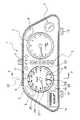
図1および図2において、コンビネーションメータ1は、本発明の車両用表示装置20と、エンジン回転計3、水温計5、ウォーニング6と、シフトインジケータ7と、表示器13と、表示器用スイッチノブ14と、を有しており、それら計器をケース10内に収容して表ガラス9で覆った状態にて、ケース10に設けられた複数の取付部12によって車両に取り付けられている。表示器13はその表示領域に、総走行距離(ODO)または区間距離(TRIP)を表示するメータと、瞬間燃費を表示するインジケータと、を有している。また、表示器用スイッチノブ14を操作することにより、ODO/TRIPの表示切り替えを行う。 1 and 2, the combination meter 1 includes a
以下の本発明に関する説明は車両用表示装置20に関するものであり、それ以外の部位については本発明とは無関係であるため説明は省略する。 The following description of the present invention relates to the
本最良の形態では、本発明の車両用表示装置20が、速度計と燃料計との2つの表示対象を組み合わせて一つの表示装置とする場合について説明するが、本発明はこれに限定するものではなく、例えば、速度計と温度計、エンジン回転計と燃料系など種々異なる組み合わせとすることができる。さらには表示対象を3つ以上の組み合わせることも可能である。 In the best mode, the case where the
本発明の車両用表示装置20の構成について以下に説明する。 The configuration of the
図1および図2に示す車両用表示装置20は、装飾部材21と、第1文字板22と、第2文字板23と、第1指針27と、第1指標24と、第1目盛26と、第2指針28と、第2指標25と、光源53と、第1内機44と、第2内機45と、配線板50と、反射面51と、拡散板52と、を有する。 The
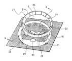
装飾部材21は、図2乃至図4に示すように、透光性の合成樹脂から成り且つ略円状の環状部21aと略扇形状の第2文字板23を一体として形成されている。またツメ70を有し、第1文字板22に設けられたツメ孔71と嵌合させることで第1文字板22上に固定される。装飾部材21はその環状部21aで第1文字板22および第2文字板23の表示領域Eを画定し、且つ第1文字板透光部29上に、利用者に視認可能となるように配置される。 As shown in FIGS. 2 to 4, the
装飾部材21の環状部21aには、第1指標24に対応する位置に第1目盛26が配置される。この第1目盛26は、半透光性着色層で形成されており、第1文字板透光部29から導光された光を受け発光する。第1目盛26以外の部分は不透光性着色層21bを設けてあり、第1文字板透光部29から導光された光を遮断する。 A
第1文字板22は、図3乃至図4に示すように透光性の合成樹脂で板状に形成されており、その前面(利用者と対向する側)に現在速度の測定量を指示するための文字と、記号等の第1指標24および背後からの照明を装飾部材21に導光するための第1文字板透光部29を有している。第1指標24および第1文字板透光部29以外の領域は不透光性着色層22aを設けることで背面からの照明による光を遮断する。また第1文字板22は、装飾部材21を固定するためのツメ70を嵌合するツメ孔71、および第1指針軸40、第2指針軸41を貫通させる第1指針軸貫通孔42,第2指針軸貫通孔43を有する。 As shown in FIGS. 3 to 4, the
第1指標24は、第1文字板22の前面から視認可能となるように、文字、記号等の形状をした半透光性着色層で構成された領域であり、背後からの照明光によって発光する。第1指標24は、第1指針27の可動範囲に対応した略円弧状に配置される。 The
第1文字板透光部29は、第1文字板22上に設けられた装飾部材21の前面投影形状をした無着色領域であり、背後からの照明を装飾部材21に導光する。 The first dial
第2文字板23は、装飾部材21の一部分として形成され略扇形状をしており、その前面に燃料残量の測定値を指示する第2指標25を有する。また第2文字板23は第2指標25以外の表面部分に、鏡面加工によって不透光性着色層23aを形成した鏡面部を有している。装飾部材21のツメ70とツメ孔71を嵌合し、装飾部材21を第1文字板22上に固定することにより、第2文字板23は第1文字板22に接した状態でその前面に配置される。 The
第2指標25は、第2文字板23の前面から視認可能となるように、文字、目盛、記号等の形状をした無着色または半透光性着色層で構成された領域であり、第1文字板透光部29により導光された照明を背後から受け、利用者に対して発光する。第2指標25は、第2指針28の可動範囲内に略円弧状に配置される。 The
第1指針27は、第1指標と共に現在速度の測定量を指示する。第1指針軸貫通孔42を貫通し第1内機44から第1文字板22前面側に延伸している第1指針軸40の先端に固着されており、第1内機44によって測定量に応じた位置に回動されることで、第1指標24、第1目盛26等を指示する。 The
第2指針28は、第2指標と共に燃料残量の測定値を指示する。第2指針軸貫通孔43を貫通し第2内機45から第1文字板22前面側に延伸している第2指針軸41の先端に固着されており、第2内機45によって測定量に応じた位置に回動されることで、第2指標25等を指示する。 The
第1内機44は、回路パターンが設けられている配線板50の裏カバー11に対向する面側に固定されており、現在速度の測定量に応じてその可動範囲内で第1指針27を駆動する。 The first
第2内機45は、回路パターンが設けられている配線板50の裏カバー11に対向する面側に固定されており、燃料残量の測定量に応じてその可動範囲内で第2指針28を駆動する。 The second
光源53は、配線板50の第1文字板22と対向する面側に配置され、それから発せられる光は直接または反射面51および拡散板52にて拡散され、第1文字板22上の第1指標24および第1文字板透光部29を通過し、さらに第1文字板透光部29上に配置された装飾部材21上の第1目盛26および第2指標25を経由して利用者側へ放射される。 The
次に、上述した本発明に係る車両用表示装置20の動作(作用)の一例を説明する。 Next, an example of the operation (action) of the
図示しない制御部からの制御によって光源53が点灯すると、その光は直接又は反射面51および拡散板52で反射して、その一部(図4光路a)は第1指標24に入射しそこから利用者に向かい放射される。また光の他の一部(図4光路bおよび光路c)は第1文字板透光部29を透過して装飾部材21に入射し、さらには第1目盛26(光路b)および第2指標25(光路c)から利用者に対し放射される。上記放射された光により、各指標および目盛は発光する。 When the
このように動作することによって、第1目盛26および第2指標25は、第1指標24が配置されている第1文字板22よりも利用者に近い位置にあるため、その発光により手前に浮揚した視覚効果を利用者に認識させることが出来る。また、第2文字板23表面には鏡面加工が施されており、車輌用表示装置外から入射した外光を反射して光輝を放つため、さらなる高級感を演出することが出来る。よって、これら効果により立体感のある斬新な表示を行うことができる。 By operating in this way, the
上述した本最良の形態において、第1文字板22および第2文字板23を照明する光源は共通であるものとして説明したが、第1文字板22を照明する光源と第2文字板23を照明する光源を別々のものとし、それぞれの光源が他方と干渉することを防ぐ遮光板を設けることで、光源の色または点灯動作を変えることが出来るため、第1文字板および第2文字板で異なる表示とすることが可能となり、これにより新たな視覚効果を得ることが出来る。 In the best mode described above, the light source that illuminates the
また、上述した本最良の形態では、第2指標について浮揚した視覚効果を得るための説明をしたが、本発明はこれに限定したものではなく、たとえば第2指標の一部(燃料残量少による警告領域等)についてのみ前記視覚効果を得る場合や、または第1指標および第2指標それぞれの一部についてのみ前記視覚効果を得る場合など種々異なる実施形態とすることができる。 In the above-described best mode, the description has been given to obtain the floating visual effect for the second index. However, the present invention is not limited to this, and for example, a part of the second index (low fuel remaining amount). Or the like, or when the visual effect is obtained only for a part of each of the first index and the second index.
また、上述した本最良の形態では、第2文字板を第1文字板前面に接して配置する説明をしたが、第2文字板を第1文字板前面との間に空間を設けてさらに前面に配置する形態など様々な実施形態とすることができる。Further, in the above-described best mode, the second dial plate is described in contact with the front surface of the first dial plate. However, a space is provided between the second dial plate and the front surface of the first dial plate, and the front surface is further increased. it can be arranged to forma throat various embodiments.
なお、上述した本最良の形態は、本発明の代表的な形態を示したに過ぎず、本発明は、実施形態に限定されるものではない。即ち、本発明の骨子を逸脱しない範囲で種々変形して実施することができる。 The best mode described above is merely a representative mode of the present invention, and the present invention is not limited to the embodiment. That is, various modifications can be made without departing from the scope of the present invention.
1 コンビネーションメータ
20 車両用表示装置
21 装飾部材
22 第1文字板
23 第2文字板
24 第1指標
25 第2指標
26 第1目盛
a 第1指標に入射する光路
b 第1目盛に入射する光路
c 第2指標に入射する光路DESCRIPTION OF SYMBOLS 1
Claims (1)
Translated fromJapanese前記装飾部材が前面に取り付けられた第1文字板を有し、
前記第1文字板の前面には、前記第1文字板の背後からの光を導光するように前記装飾部材の前面投影形状に形成され、前記装飾部材がその形状に沿って重ねて配置された第1文字板透光部と、不透光性着色層が形成された前記第1文字板透光部の内側の部分と、が設けられ、
前記装飾部材には、前記表示領域を囲うように形成された環状部と、前記第1文字板の前面側にずれた状態で前記表示領域内に位置づけられるように前記環状部の内縁の一部に一体に形成された、前記第1文字板の前面における前記第1文字板透光部の内側の部分より小さい第2文字板と、が設けられ、
前記第1文字板の前面における前記第1文字板透光部の内側の部分には、前記第1指標が前記第1文字板の背後からの光を透過して発光するように設けられ、
前記第2文字板には、前記第2指標が前記第1文字板透光部からの光を透過して発光するように設けられている
ことを特徴とする車両用表示装置。A vehicular display device havinga decorative memberformed in a ring shape with a translucent member so as to demarcate display areas fordisplaying first and second indicators corresponding todifferent types of display objects,
The decorative member has a first dial attached to the front surface,
A front projection of the decorative member is formed on the front surface of the first dial so as to guide light from behind the first dial, and the decorative member is arranged so as to overlap the shape. A first dial transparent portion and an inner portion of the first transparent dial portion on which an opaque color layer is formed,
Wherein the decorative member,the inner edge ofthe and formed annular portion so as to surround the display area, whereinthe annular portion as can be positionedbefore Symbol display region with a shifton the front side of the first dialone A second dialsmaller than theinner portion of the first dial translucent portion on the front surface of the first dial, whichis integrally formed withthe first dial,
The first indicator is provided on the inner surface of the first dial transparent portion on the front surface of the first dial so that the first indicator transmits light from behind the first dial and emits light.
The vehicle display device, wherein the second dial is provided so that the second indicator transmits light from the first dial transparent portion .
Priority Applications (1)
| Application Number | Priority Date | Filing Date | Title |
|---|---|---|---|
| JP2006316997AJP4989196B2 (en) | 2006-11-24 | 2006-11-24 | Vehicle display device |
Applications Claiming Priority (1)
| Application Number | Priority Date | Filing Date | Title |
|---|---|---|---|
| JP2006316997AJP4989196B2 (en) | 2006-11-24 | 2006-11-24 | Vehicle display device |
Publications (2)
| Publication Number | Publication Date |
|---|---|
| JP2008128947A JP2008128947A (en) | 2008-06-05 |
| JP4989196B2true JP4989196B2 (en) | 2012-08-01 |
Family
ID=39554899
Family Applications (1)
| Application Number | Title | Priority Date | Filing Date |
|---|---|---|---|
| JP2006316997AActiveJP4989196B2 (en) | 2006-11-24 | 2006-11-24 | Vehicle display device |
Country Status (1)
| Country | Link |
|---|---|
| JP (1) | JP4989196B2 (en) |
Families Citing this family (1)
| Publication number | Priority date | Publication date | Assignee | Title |
|---|---|---|---|---|
| JP5316429B2 (en)* | 2010-01-12 | 2013-10-16 | 株式会社デンソー | Mounting structure for vehicle display device |
Family Cites Families (2)
| Publication number | Priority date | Publication date | Assignee | Title |
|---|---|---|---|---|
| JPS61195412U (en)* | 1985-05-28 | 1986-12-05 | ||
| JP4698187B2 (en)* | 2004-09-07 | 2011-06-08 | 矢崎総業株式会社 | Dial and meter device using the same |
- 2006
- 2006-11-24JPJP2006316997Apatent/JP4989196B2/enactiveActive
Also Published As
| Publication number | Publication date |
|---|---|
| JP2008128947A (en) | 2008-06-05 |
Similar Documents
| Publication | Publication Date | Title |
|---|---|---|
| CN104567970B (en) | pointer instrument | |
| JP4977447B2 (en) | Vehicle display device | |
| JP4963597B2 (en) | Display device | |
| JP5218194B2 (en) | Mobile instrument | |
| JP4840061B2 (en) | Instrument device | |
| JP4882092B2 (en) | Indicating instrument | |
| JP4977403B2 (en) | Vehicle display device | |
| JP4792831B2 (en) | Instrument display board and pointer instrument having the same | |
| JP2009180623A (en) | Indicating instrument | |
| JP4989196B2 (en) | Vehicle display device | |
| JP2002023669A (en) | Display device | |
| JP5207136B2 (en) | Pointer type display device | |
| JP4858228B2 (en) | Pointer instrument | |
| JP4820224B2 (en) | Vehicle instrument | |
| JP5627482B2 (en) | Pointer member, pointer unit, and pointer instrument | |
| JP2008203061A (en) | Display device | |
| JP2002372441A (en) | Vehicle measuring instrument | |
| JP4224751B2 (en) | Display device | |
| JP4075843B2 (en) | Vehicle indicator instrument | |
| JP6020048B2 (en) | Instrument device | |
| JP5134491B2 (en) | Instrument device | |
| JP4265514B2 (en) | Vehicle indicator instrument | |
| JP2006113024A (en) | Pointing instrument | |
| JP4796720B2 (en) | Self-luminous pointer and pointer-type display device | |
| JP4904125B2 (en) | Self-luminous pointer and vehicle display device |
Legal Events
| Date | Code | Title | Description |
|---|---|---|---|
| A621 | Written request for application examination | Free format text:JAPANESE INTERMEDIATE CODE: A621 Effective date:20091028 | |
| A131 | Notification of reasons for refusal | Free format text:JAPANESE INTERMEDIATE CODE: A131 Effective date:20111220 | |
| A521 | Request for written amendment filed | Free format text:JAPANESE INTERMEDIATE CODE: A523 Effective date:20120220 | |
| TRDD | Decision of grant or rejection written | ||
| A01 | Written decision to grant a patent or to grant a registration (utility model) | Free format text:JAPANESE INTERMEDIATE CODE: A01 Effective date:20120424 | |
| A01 | Written decision to grant a patent or to grant a registration (utility model) | Free format text:JAPANESE INTERMEDIATE CODE: A01 | |
| A61 | First payment of annual fees (during grant procedure) | Free format text:JAPANESE INTERMEDIATE CODE: A61 Effective date:20120427 | |
| R150 | Certificate of patent or registration of utility model | Ref document number:4989196 Country of ref document:JP Free format text:JAPANESE INTERMEDIATE CODE: R150 Free format text:JAPANESE INTERMEDIATE CODE: R150 | |
| FPAY | Renewal fee payment (event date is renewal date of database) | Free format text:PAYMENT UNTIL: 20150511 Year of fee payment:3 | |
| R250 | Receipt of annual fees | Free format text:JAPANESE INTERMEDIATE CODE: R250 | |
| R250 | Receipt of annual fees | Free format text:JAPANESE INTERMEDIATE CODE: R250 | |
| R250 | Receipt of annual fees | Free format text:JAPANESE INTERMEDIATE CODE: R250 | |
| R250 | Receipt of annual fees | Free format text:JAPANESE INTERMEDIATE CODE: R250 | |
| R250 | Receipt of annual fees | Free format text:JAPANESE INTERMEDIATE CODE: R250 | |
| R250 | Receipt of annual fees | Free format text:JAPANESE INTERMEDIATE CODE: R250 | |
| R250 | Receipt of annual fees | Free format text:JAPANESE INTERMEDIATE CODE: R250 | |
| R250 | Receipt of annual fees | Free format text:JAPANESE INTERMEDIATE CODE: R250 | |
| S531 | Written request for registration of change of domicile | Free format text:JAPANESE INTERMEDIATE CODE: R313531 | |
| R350 | Written notification of registration of transfer | Free format text:JAPANESE INTERMEDIATE CODE: R350 | |
| R250 | Receipt of annual fees | Free format text:JAPANESE INTERMEDIATE CODE: R250 |