JP4987883B2 - Apparatus and method for connecting a cleaning tool to a floor cleaner - Google Patents
Apparatus and method for connecting a cleaning tool to a floor cleanerDownload PDFInfo
- Publication number
- JP4987883B2 JP4987883B2JP2008553498AJP2008553498AJP4987883B2JP 4987883 B2JP4987883 B2JP 4987883B2JP 2008553498 AJP2008553498 AJP 2008553498AJP 2008553498 AJP2008553498 AJP 2008553498AJP 4987883 B2JP4987883 B2JP 4987883B2
- Authority
- JP
- Japan
- Prior art keywords
- cleaning tool
- slot
- edge
- coupling device
- floor
- Prior art date
- Legal status (The legal status is an assumption and is not a legal conclusion. Google has not performed a legal analysis and makes no representation as to the accuracy of the status listed.)
- Expired - Fee Related
Links
- 238000004140cleaningMethods0.000titleclaimsdescription125
- 238000000034methodMethods0.000titledescription7
- 230000008878couplingEffects0.000claimsdescription74
- 238000010168coupling processMethods0.000claimsdescription74
- 238000005859coupling reactionMethods0.000claimsdescription74
- 230000033001locomotionEffects0.000claimsdescription7
- 239000000463materialSubstances0.000claimsdescription5
- 230000000295complement effectEffects0.000claimsdescription4
- 238000000926separation methodMethods0.000claims2
- 238000003780insertionMethods0.000description6
- 230000037431insertionEffects0.000description6
- 239000012530fluidSubstances0.000description3
- 230000005540biological transmissionEffects0.000description1
- 238000010276constructionMethods0.000description1
- 230000014509gene expressionEffects0.000description1
- 230000002452interceptive effectEffects0.000description1
- 238000012423maintenanceMethods0.000description1
- 238000011017operating methodMethods0.000description1
- 230000008520organizationEffects0.000description1
- 238000005498polishingMethods0.000description1
- 238000012545processingMethods0.000description1
- 238000005507sprayingMethods0.000description1
- 238000003466weldingMethods0.000description1
Images


Classifications
- A—HUMAN NECESSITIES
- A47—FURNITURE; DOMESTIC ARTICLES OR APPLIANCES; COFFEE MILLS; SPICE MILLS; SUCTION CLEANERS IN GENERAL
- A47L—DOMESTIC WASHING OR CLEANING; SUCTION CLEANERS IN GENERAL
- A47L11/00—Machines for cleaning floors, carpets, furniture, walls, or wall coverings
- A47L11/40—Parts or details of machines not provided for in groups A47L11/02 - A47L11/38, or not restricted to one of these groups, e.g. handles, arrangements of switches, skirts, buffers, levers
- A47L11/4036—Parts or details of the surface treating tools
- A—HUMAN NECESSITIES
- A47—FURNITURE; DOMESTIC ARTICLES OR APPLIANCES; COFFEE MILLS; SPICE MILLS; SUCTION CLEANERS IN GENERAL
- A47L—DOMESTIC WASHING OR CLEANING; SUCTION CLEANERS IN GENERAL
- A47L11/00—Machines for cleaning floors, carpets, furniture, walls, or wall coverings
- A47L11/02—Floor surfacing or polishing machines
- A47L11/10—Floor surfacing or polishing machines motor-driven
- A47L11/12—Floor surfacing or polishing machines motor-driven with reciprocating or oscillating tools
- A—HUMAN NECESSITIES
- A47—FURNITURE; DOMESTIC ARTICLES OR APPLIANCES; COFFEE MILLS; SPICE MILLS; SUCTION CLEANERS IN GENERAL
- A47L—DOMESTIC WASHING OR CLEANING; SUCTION CLEANERS IN GENERAL
- A47L11/00—Machines for cleaning floors, carpets, furniture, walls, or wall coverings
- A47L11/02—Floor surfacing or polishing machines
- A47L11/10—Floor surfacing or polishing machines motor-driven
- A47L11/14—Floor surfacing or polishing machines motor-driven with rotating tools
- A47L11/18—Floor surfacing or polishing machines motor-driven with rotating tools the tools being roll brushes
- A47L11/19—Parts or details of the brushing tools
- Y—GENERAL TAGGING OF NEW TECHNOLOGICAL DEVELOPMENTS; GENERAL TAGGING OF CROSS-SECTIONAL TECHNOLOGIES SPANNING OVER SEVERAL SECTIONS OF THE IPC; TECHNICAL SUBJECTS COVERED BY FORMER USPC CROSS-REFERENCE ART COLLECTIONS [XRACs] AND DIGESTS
- Y10—TECHNICAL SUBJECTS COVERED BY FORMER USPC
- Y10T—TECHNICAL SUBJECTS COVERED BY FORMER US CLASSIFICATION
- Y10T29/00—Metal working
- Y10T29/49—Method of mechanical manufacture
- Y10T29/49826—Assembling or joining
- Y—GENERAL TAGGING OF NEW TECHNOLOGICAL DEVELOPMENTS; GENERAL TAGGING OF CROSS-SECTIONAL TECHNOLOGIES SPANNING OVER SEVERAL SECTIONS OF THE IPC; TECHNICAL SUBJECTS COVERED BY FORMER USPC CROSS-REFERENCE ART COLLECTIONS [XRACs] AND DIGESTS
- Y10—TECHNICAL SUBJECTS COVERED BY FORMER USPC
- Y10T—TECHNICAL SUBJECTS COVERED BY FORMER US CLASSIFICATION
- Y10T29/00—Metal working
- Y10T29/53—Means to assemble or disassemble
Landscapes
- Cleaning In General (AREA)
- Nozzles For Electric Vacuum Cleaners (AREA)
- Cleaning Implements For Floors, Carpets, Furniture, Walls, And The Like (AREA)
- Brushes (AREA)
Description
Translated fromJapanese本発明は、床清掃具を床清掃機に連結する装置及び方法に関する。床清掃機は、スクラバー、掃除機等の、多くのタイプの床清掃・処理機のうちの1つであり得る。これらのタイプの清掃機は、ホテル、工場、オフィスビル、ショッピングセンター等の広範な床面積の固い表面を清掃するために用いることができる。 The present invention relates to an apparatus and method for connecting a floor cleaning tool to a floor cleaning machine. The floor cleaner can be one of many types of floor cleaning and processing machines, such as scrubbers, vacuum cleaners and the like. These types of cleaners can be used to clean hard surfaces with a wide floor area such as hotels, factories, office buildings, shopping centers and the like.
一般的に、そのような清掃機は、一対の駆動ホイールと1つ又は複数のキャスタホイールとによって支持される移動可能な本体を備える。スクラバーの場合、本体は、洗浄装置、未使用及び使用済みの洗浄液を保管するリザーバ、未使用の洗浄液を床に散布する装置、並びに床から使用済みの洗浄液を回収するスクイジー/真空収集(pickup)システムを有する。 In general, such a cleaner comprises a movable body supported by a pair of drive wheels and one or more caster wheels. In the case of a scrubber, the body is a cleaning device, a reservoir for storing unused and used cleaning fluid, a device for spraying unused cleaning fluid to the floor, and a squeegee / pickup to collect used cleaning fluid from the floor I have a system.
洗浄装置は通常、ブラシ若しくは洗浄パッド等の1つ又は複数の清掃具、及び清掃具を駆動するモータを備える。 A cleaning device typically includes one or more cleaning tools such as brushes or cleaning pads, and a motor that drives the cleaning tools.
床清掃機のパッドは、摩耗に起因して、又は異なる研磨特性を有するパッドを使用する必要があることによって頻繁に交換されるため、連結装置のリテーナ部分が容易に解放されることが重要である。 It is important that the retainer part of the coupling device be easily released because floor cleaner pads are frequently replaced due to wear or the need to use pads with different polishing characteristics. is there.
本発明は、床清掃具を床清掃機に連結する装置及び方法に関する。この装置及び方法は、パッド又はブラシ等の床清掃具を、容易に解放及び接続することができるように選択的に連結する。 The present invention relates to an apparatus and method for connecting a floor cleaning tool to a floor cleaning machine. The apparatus and method selectively couples floor cleaning tools such as pads or brushes so that they can be easily released and connected.
本発明の一実施の形態は、清掃具を床清掃機に連結する装置を提供する。この連結装置は、第1の縁と、第2の縁と、当該第1の縁及び当該第2の縁間に延びる本体部分とを有するプレートを備える。第1のスロットがプレートの第1の縁に連結される。第1のスロットは、清掃具の第1の縁を受け取るような寸法にされ、且つ受け取るように構成される。第2のスロットがプレートの第2の縁に連結される。第2のスロットは、清掃具の第2の縁を受け取るような寸法にされ、且つ受け取るように構成される。第2のスロットは、挿入時に清掃具の縁を最初に受け取る第1の端と、第2の端であって、清掃具が当該第2の端を介して第2のスロットから離れることを防止する突出部材に隣接して配置される、第2の端とを有する。第2のスロットの第1の端は、清掃具が第1の端を介して第2のスロットから離れることを選択的に防止する、選択的に移動可能な突出部材を有する。 One embodiment of the present invention provides an apparatus for coupling a cleaning tool to a floor cleaner. The coupling device comprises a plate having a first edge, a second edge, and a body portion extending between the first edge and the second edge. A first slot is connected to the first edge of the plate. The first slot is sized and configured to receive the first edge of the cleaning tool. A second slot is connected to the second edge of the plate. The second slot is sized and configured to receive the second edge of the cleaning tool. The second slot is a first end that first receives an edge of the cleaning tool upon insertion, and a second end to prevent the cleaning tool from leaving the second slot through the second end. And a second end disposed adjacent to the protruding member. The first end of the second slot has a selectively movable projecting member that selectively prevents the cleaning tool from leaving the second slot via the first end.
いくつかの実施の形態では、本体部分は、清掃具から延びる凸状の突起を選択的に受け取るような寸法にされ、且つ受け取るように構成される複数の凹部を有する。清掃具の突起は、アクチュエータが清掃具を床に対して押圧すると連結装置の凹部に完全に専ら係合する。 In some embodiments, the body portion has a plurality of recesses sized and configured to selectively receive convex protrusions extending from the cleaning tool. The protrusion of the cleaning tool is completely engaged with the recess of the coupling device when the actuator presses the cleaning tool against the floor.
他の実施の形態では、本体部分は、清掃具の方へ延びる複数の実質的に凸状の突起を有する。この突起は、清掃具の実質的に凹部内に選択的に受け取られるような寸法にされ、且つ選択的に受け取られるように構成される。清掃具の凹部は、アクチュエータが清掃具を床に対して押圧すると連結装置の突起に完全に専ら係合する。 In other embodiments, the body portion has a plurality of substantially convex protrusions extending toward the cleaning tool. The protrusion is sized and configured to be selectively received substantially within the recess of the cleaning tool. The recess of the cleaning tool is completely engaged with the projection of the coupling device when the actuator presses the cleaning tool against the floor.
別の実施の形態は、床清掃機に連結される清掃具を駆動する装置に関する。清掃具は、この装置の方へ延びる複数の突起又は凹部を含む。装置は、清掃具から延びる突起又は凹部を選択的に受け取るような寸法にされ、且つ選択的に受け取るように構成される複数の実質的に相補的な凹部又は突起を有するプレートを含む。これらの凹部及び突起は、アクチュエータが清掃具を床に対して押圧すると互いに完全に専ら係合する。 Another embodiment relates to an apparatus for driving a cleaning tool coupled to a floor cleaner. The cleaning tool includes a plurality of protrusions or recesses that extend toward the device. The apparatus includes a plate sized and configured to selectively receive a protrusion or recess extending from the cleaning tool and having a plurality of substantially complementary recesses or protrusions configured to receive selectively. These recesses and protrusions are completely engaged with each other when the actuator presses the cleaning tool against the floor.
別の実施の形態は床清掃機に関する。この床清掃機は、フレームと、フレームに連結されるアクチュエータと、アクチュエータに連結される連結装置と、連結装置に連結される清掃具とを含む。清掃具は、床表面と接触して清掃するようになっている第1の表面と、第1の表面と実質的に対向して配置されて連結装置と接触するようになっている第2の表面とを有する。第2の表面は、第2の表面から延びる複数の突出部材を有する。清掃具は、第2の表面から第1の表面の方へ延びる、実質的に対向する第1の縁及び第2の縁も有する。連結装置は、第1の縁と、第2の縁と、当該第1の縁及び当該第2の縁間に延びる本体部分とを有するプレートを備える。本体部分は、清掃具から延びる突起を選択的に受け取るような寸法にされ、且つ選択的に受け取るように構成される複数の凹部を有する。第1のスロットがプレートの第1の縁に連結される。第1のスロットは、清掃具の第1の縁を受け取るような寸法にされ、且つ受け取るように構成される。第2のスロットがプレートの第2の縁に連結される。第2のスロットは、清掃具の第2の縁を受け取るような寸法にされ、且つ受け取るように構成される。第2のスロットは、挿入時に清掃具の縁を最初に受け取る第1の端と、第2の端であって、清掃具が当該第2の端を介して第2のスロットから離れることを防止する突出部材に隣接して配置される、第2の端とを有する。第2のスロットの第1の端は、清掃具が第1の端を介して第2のスロットから離れることを選択的に防止する、選択的に移動可能な突出部材を有する。清掃具の突起は、アクチュエータが清掃具を床に対して押圧すると連結装置の凹部に専ら係合する。 Another embodiment relates to a floor cleaner. The floor cleaning machine includes a frame, an actuator coupled to the frame, a coupling device coupled to the actuator, and a cleaning tool coupled to the coupling device. The cleaning tool has a first surface adapted to be cleaned in contact with the floor surface, and a second surface disposed substantially opposite the first surface and adapted to contact the coupling device. And having a surface. The second surface has a plurality of protruding members extending from the second surface. The cleaning tool also has first and second substantially opposing edges that extend from the second surface toward the first surface. The coupling device comprises a plate having a first edge, a second edge, and a body portion extending between the first edge and the second edge. The body portion has a plurality of recesses sized and configured to selectively receive protrusions extending from the cleaning tool. A first slot is connected to the first edge of the plate. The first slot is sized and configured to receive the first edge of the cleaning tool. A second slot is connected to the second edge of the plate. The second slot is sized and configured to receive the second edge of the cleaning tool. The second slot is a first end that first receives an edge of the cleaning tool upon insertion, and a second end to prevent the cleaning tool from leaving the second slot through the second end. And a second end disposed adjacent to the protruding member. The first end of the second slot has a selectively movable projecting member that selectively prevents the cleaning tool from leaving the second slot via the first end. The protrusion of the cleaning tool is exclusively engaged with the recess of the coupling device when the actuator presses the cleaning tool against the floor.
本発明のさらなる態様は、その構成(organization)及び動作と共に、添付の図面と併せて読むと本発明の以下の詳細な説明から明らかになるであろう。 Further aspects of the present invention, as well as its organization and operation, will become apparent from the following detailed description of the invention when read in conjunction with the accompanying drawings.
本発明のいかなる実施形態も詳細に説明する前に、本発明は、その適用が、以下の説明に記載されるか、又は添付の図面に示される構造の詳細及び構成要素の配置に限定されないことを理解されたい。本発明は、他の実施形態が可能であり、また種々の方法で実行するか又は実施することが可能である。また、本明細書で使用される表現及び用語は説明のためのものであり、限定されるものとしてみなすべきではないことを理解されたい。本明細書において、「含む(including)」、「備える(comprising)」、又は「有する(having)」、及びその変化形の使用は、それに続いて列挙される構成要素(item)、その均等物、及びさらなる構成要素を包含することを意味する。「取り付けられる」、「接続される」、及び「連結される」という用語は、広範に用いられ、直接的及び間接的両方の取り付け、接続及び連結を包含する。さらに、「接続される」及び「連結される」は、物理的若しくは機械的な接続又は連結に限定されず、直接的であれ間接的であれ電気的な接続又は連結を含むことができる。最後に、以下の段落で述べるように、図面に示される特定の機械的な構成は、本発明の実施形態を例示することを意図する。したがって、他の代替的な機械的な構成が可能であり、本発明の精神及び範囲内に入る。 Before describing any embodiments of the present invention in detail, the present invention is not limited in its application to the details of construction and the arrangement of components set forth in the following description or illustrated in the accompanying drawings. I want you to understand. The invention is capable of other embodiments and of being practiced or carried out in various ways. It should also be understood that the expressions and terms used herein are for purposes of illustration and should not be considered as limiting. In this specification, the use of “including”, “comprising”, or “having”, and variations thereof, is an enumerated item, its equivalents , And additional components. The terms “attached”, “connected” and “coupled” are used extensively and encompass both direct and indirect attachment, connection and coupling. Further, “connected” and “coupled” are not limited to physical or mechanical connections or couplings, and can include electrical connections or couplings, whether direct or indirect. Finally, as described in the following paragraphs, the specific mechanical configuration shown in the drawings is intended to exemplify embodiments of the invention. Accordingly, other alternative mechanical configurations are possible and are within the spirit and scope of the present invention.
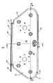
ここで図1を参照すると、床清掃機10が示され、この床清掃機10は、洗浄パッド及びブラシ等の清掃具14を清掃機10に連結するのに使用される装置12を備える。本発明の特定の一実施形態はスクラバーに関連して説明するが、本発明は、掃除機等の他のタイプの床整備手段(vehicles)に適用できることが明らかであろう。したがって、本発明はスクラバーに限定されるべきではない。 Referring now to FIG. 1, a
ここで図2〜図6を参照すると、連結装置12の特定の一実施形態が示されている。以下でさらに詳細に説明するように、この図示の連結装置12は、清掃具14を軌道運動又は往復運動で移動させるようになっている。しかし、本明細書に示す原理は回転運動にも適合することができる。 Referring now to FIGS. 2-6, one particular embodiment of the
図2においてわかるように、清掃具14及び連結装置12は、この清掃装置の軌道運動のために概ね細長い。しかし、他の実施形態では、清掃具14は、正方形、矩形、円形、他の多角形形状等、種々の他の構成を有することができる。 As can be seen in FIG. 2, the
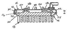
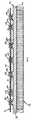
清掃具14の2つの特定の実施形態が図7及び図8に示される。図7は、ブラシ型の清掃具14を示し、図8は清掃パッド型の清掃具14を示す。これらの図に示されるように、清掃具14は両方とも、ブラシ又はパッドを連結装置12に連結するのに使用される実質的に同様の固定部分16を有する。図示の実施形態のこの固定部分16及び清掃部分18は、概ね台形形状であるが、他の構成も可能である。固定部分16は、第1の長手方向縁22と、当該第1の長手方向縁22に対向して配置される第2の長手方向縁24とを有する本体20を有する。第1の長手方向縁22及び第2の長手方向縁24は清掃要素18にわたってわずかに片持ち梁式になっている。 Two specific embodiments of the
複数の位置決め部材26が固定部分16の上側に連結されている。これらの位置決め部材26は、種々の材料から作製されることができ、且つ多くの異なる方法で構成することができる。図示の実施形態では、位置決め部材26は概ね凸状形状を有するゴム突起である。詳細には、ゴム突起はドーム状又は円錐台形の構成を有する。以下で説明するように、このタイプの形状は、位置決め部材を連結装置12の受け取り凹部(receiving recesses)28に位置決めするか又は向けるのに役立ち得る。この実施形態の突起26は、清掃具14及び連結装置12間の騒音を抑えるのに役立つようにゴムから形成される。しかし、他の材料をこの同じ目的のために使用することができる。 A plurality of
図示の実施形態は突出している位置決め部材26を清掃具14の固定部分16、及び連結装置12の受け取り凹部28に位置付けるが、他の実施形態はこの構成を変更してもよい。例えば、いくつかの実施形態では、突起26を連結装置12に位置付け、凹部28を清掃具14の固定部分16に位置付けることができる。さらに、いくつかの実施形態は、突起26及び凹部28の組み合わせを、清掃具の固定部分16及び連結装置12の両方に使用することができる。 Although the illustrated embodiment positions the protruding positioning
図2に示し、以下でさらに詳細に説明するように、清掃具14、すなわちより詳細には清掃具14の固定部分16は、清掃具14を床清掃機10に接続するために連結装置12内に受け取られる。 As shown in FIG. 2 and described in more detail below, the
連結装置12は、清掃具14の固定部分16の縁22、24を受け取る一対のスロット32を有する本体30を含む。スロット32は、固定部分16の縁22、24を受け取るような寸法にされ、且つ受け取るように構成される。より詳細には、図4及び図5に示すように、スロット32は、位置決め部材26及び連結装置12の本体30間で著しい干渉又は係合を伴うことなく、固定部分16を連結装置12内へ容易に滑り込ませることができるような寸法にされる。 The
図2及び図3に示すように、スロット32のうちの一方は、清掃具14が連結装置12から外れることを選択的に防止するリテーナ34を有する。リテーナ34は、スロット32の一端に隣接して配置され、スロット32によって画定される経路と交差する突起36を含む。リテーナ34は、スロット32の他端に隣接して配置され、スロット32によって画定される経路と交差する別の突起38も含む。突起36、38のうちの少なくとも一方が、清掃具14を連結装置12から取り外すことができる非交差位置まで選択的に移動可能である。図示の実施形態では、一方のみの突起38が選択的に移動可能である。この突起38には、操作者がリテーナ34を弾性変形させるか又は他の方法で突起38を移動させるためのてこの作用を提供するレバー40が設けられる。図3にさらに示されるように、この端に位置決めされる突起38は、突起38をレバー40で手動で移動させることなく清掃具14を挿入することができるように角度が付けられている。むしろ、突起38の角度の付いた構成によって、突起38は、挿入時に清掃具14の固定部分16の縁22と係合すると、自然に外方へと押しやられる。 As shown in FIGS. 2 and 3, one of the
図示の実施形態では、リテーナ34はスロット32とは別個に形成され、溶接等の二次的な作業においてスロット32に取り付けられる。しかし、他の実施形態では、リテーナ34はスロット32又は本体部分30内に一体的に形成されてもよい。 In the illustrated embodiment, the
図2〜図6に示すように、連結装置12の本体部分30には複数の凹部28が設けられる。これらの凹部28は、清掃具14の上部から延びる突起26の部分を選択的に収容するか若しくは受け取るような寸法にされるか、又はそのように構成される。凹部28は、突起26を受け取る概ね凹状の構成を有する。概ね凹部28は、ドーム状構成又は清掃具14の突起26の構成に似た幾分円錐形の構成を有する。さらに、凹部28は、清掃具14の突起26と実質的に同じ構成で概ね離間して配置される。 As shown in FIGS. 2 to 6, the
作業時には、図7に示すブラシのような清掃具14を、図2〜図6に示される連結装置12を介して以下のように床清掃機10に連結することができる。まず、清掃具14を連結装置12と整合させる。詳細には、清掃具14の固定部分16の片持ち梁式縁22、24を、連結装置12のスロット32と整合させる。この整合が実質的に完了すると、清掃具14を、連結装置12のスロット32内へ挿入、押し込み、駆動、又は他の方法で押しやることができる。 At the time of work, the
ブラシ14が連結装置12に入ると、ブラシの縁のうちの一方がリテーナ34の角度の付いた突起38と係合し、ブラシ14がスロット32に入ることができる位置までリーテナを押しやる。挿入プロセスの間に、片持ち梁式縁22、24の底面(すなわち、作業中に床に面する表面)は好ましくは、スロット32の上向きの表面に沿って摺動する。挿入プロセスの間のこのタイプの係合によって、ブラシ14上の突起26が連結装置12の本体部分30に干渉するか又は実質的に係合することなくブラシ14が容易に挿入されるであろう。ブラシ14がスロット32内に完全に挿入されると、角度の付いた突起38がその元の位置へ弾性的に戻ることができる。この位置では、ブラシ14が連結装置12から外れることが防止され、より詳細には、片持ち梁式縁がスロット32から後退することが防止される。 As the
ブラシ14は、連結装置12内に完全に挿入されると、図4A、図5A及び図6Aに示されるように連結装置12内に係止する。詳細には、片持ち梁式縁22、24の下面がスロット32の下部に載ったままになる。さらに、これらの図に示すように、清掃具14の上部の突起26は、連結装置12の凹部28とは係合しない。しかし、突起26はこの位置で凹部28と実質的に整合され得る。 When fully inserted into the
操作者がブラシ14を使用することを選択する場合、ブラシ14及び連結装置12が下降して床と接触する。モータ又はモータ及びトランスミッションアセンブリ等のアクチュエータを用いて、ブラシ14及び連結装置12を床まで下降させることができる。アクチュエータを用いて、所望の圧力又は力で床に対してブラシ14を押しやることができる。これによって、ブラシ14を図4A、図5A、及び図6Aに示すように連結装置12と係合させる。詳細には、ブラシ14の上部から延びる突起26は、連結装置12の本体部分30の凹部28と係合する。この係合によって、ブラシ14が床に対して作動された場合に、ブラシ14が連結装置12に対して移動することが防止される。ブラシ14が床と接触して位置付けられる前に突起26が凹部28と完全に整合しないと仮定すると、突起26及び凹部28の形状が適切な整合及び係合を促すであろう。詳細には、凹部28の凹状形状と組み合わせた突起26の概ね凸状の形状は、漏斗状であるか、又はそうでなければブラシを連結装置12と適切に整合させるように移動させることができる。 When the operator chooses to use the
洗浄作業が完了すると、アクチュエータを作動してブラシ14及び連結装置12を床から上昇させることができる。ブラシ14は、床から上昇すると、図4Aに示すように連結装置12内に係止する。 When the cleaning operation is completed, the actuator can be operated to raise the
ブラシ14を連結装置12から取り外すために、以下のステップを用いることができる。角度の付いた突起38を、スロット32によって画定される経路と実質的に交差しない位置へ移動させるように突起38に隣接するレバー40に力を加えることができる。突起38が、ブラシ14の取り外しを妨げない位置へ移動すると、ブラシ14を、挿入された方向とは反対の方向へ引くことによって連結装置12から取り外すことができる。 In order to remove the
上述し、図に示した実施形態は、例示としてのみ提示され、本発明の概念及び原理に制限を加えることは意図しない。したがって、本発明の精神及び範囲から逸脱することなく、要素、それらの構成及び配置をさまざまに変更することができることは当業者に理解されるであろう。例えば、本発明の特定の特徴及び要素に対する種々の代替形態が、本発明の特定の実施形態を参照して説明される。互いに排他的であるか又は上述した各実施形態と一貫性のない特徴、要素及び操作方法(manners of operation)を例外として、特定の一実施形態を参照して説明した代替的な特徴、要素及び操作方法は、他の実施形態に適用可能であることに留意されたい。 The embodiments described above and illustrated in the figures are presented by way of example only and are not intended to limit the concepts and principles of the present invention. Thus, it will be appreciated by one skilled in the art that various changes can be made in the elements, their configuration and arrangement without departing from the spirit and scope of the present invention. For example, various alternatives to particular features and elements of the invention will be described with reference to particular embodiments of the invention. Alternative features, elements, and elements described with reference to a particular embodiment, with the exception of features, elements and methods of operation that are mutually exclusive or inconsistent with the embodiments described above. It should be noted that the operating method is applicable to other embodiments.
本発明の種々の特徴は添付の特許請求の範囲に記載される。 Various features of the invention are set forth in the appended claims.
Claims (19)
Translated fromJapaneseプレートは、第1縁と、第2縁と、第1縁と第2縁の間に延びる本体部分とを有し、該本体部分は、清掃具から延びる凸状の突起を受け取る寸法と形状を持つ複数の凹部を有し、突起と凹部は相補的な形状を備え、
第1スロットは、プレートの第1縁に連結され、清掃具の第1縁を受け取る寸法と形状を有し、
第2スロットは、プレートの第2縁に連結され、清掃具の第2縁を受け取る寸法と形状を有し、第2スロットはさらに第1端と第2端を有し、第1端は挿入時に清掃具の該縁を最初に受け取り、第2端は清掃具が第2端を介して第2スロットから離れることを防止する突出部材に隣接して配置され、第1端は清掃具が第1端を介して第2スロットから離れることを防止する移動可能な突出部材を有することを特徴とする連結装置。A connecting device for connecting a cleaning tool to a floor cleaning machine, comprising a plate and first and secondslots ,
The plate has a first edge, a second edge, and a body portion extending between the first edge and the second edge, the body portion sized and shaped toreceive a convex protrusion extending from the cleaning tool. Having a plurality ofrecesses, the protrusions and recesses have complementary shapes,
The firstslot is connected to the first edge of the plate and has a size and shape for receiving the first edge of the cleaning tool;
The secondslot is coupled to the second edge of the plate and is sized and shaped to receive the second edge of the cleaning tool, the secondslot further having a first end and a second end, the first end being inserted Sometimes the edge of the cleaning tool is first received, the second end is located adjacent to a protruding member that prevents the cleaning tool from leaving the secondslot through the second end, and the first end is A connecting device comprisinga movable projecting member forpreventing separation from the secondslot via one end.
プレートは、第1縁と、第2縁と、第1縁と第2縁の間に延びる本体部分とを有し、該本体部分は、清掃具の方へ延びると共に、清掃具の実質的に凹部内に受け取られる寸法と形状を持つ複数の実質的に凸状の突起を有し、突起と凹部は相補的な形状を備え、
第1スロットは、プレートの第1縁に連結され、清掃具の第1縁を受け取る寸法と形状を有し、
第2スロットは、プレートの第2縁に連結され、清掃具の第2縁を受け取る寸法と形状を有し、第2スロットはさらに第1端と第2端を有し、第1端は挿入時に清掃具の該縁を最初に受け取り、第2端は清掃具が第2端を介して第2スロットから離れることを防止する突出部材に隣接して配置され、第1端は清掃具が第1端を介して第2スロットから離れることを防止すると共に移動可能な突出部材を有することを特徴とする連結装置。A connecting device for connecting a cleaning tool to a floor cleaning machine, comprising a plate and first and secondslots ,
The plate has a first edge, a second edge, and a body portion extending between the first edge and the second edge, the body portion extending toward the cleaning tool and substantially of the cleaning tool. Having a plurality of substantially convex protrusions having dimensions and shapesreceived within therecesses , theprotrusions and recesses having complementary shapes;
Thefirst slot is connected to the first edge of the plate and has a size and shape for receiving the first edge of the cleaning tool;
The secondslot is coupled to the second edge of the plate and is sized and shaped to receive the second edge of the cleaning tool, the secondslot further having a first end and a second end, the first end being inserted Sometimes the edge of the cleaning tool is first received, the second end is located adjacent to a protruding member that prevents the cleaning tool from leaving the second slot through the second end, and the first end is A connecting device comprising:a projecting member that ismovable whilepreventing separation from the secondslot through one end.
清掃具は、床表面と接触して清掃する第1表面と、第1表面と実質的に対向して配置されて連結装置と接触する第2表面とを有し、第2表面は第2表面から延びる複数の突起を有し、清掃具はさらに第2表面から第1表面の方へ延びる実質的に対向する第1縁と第2縁を有し、
連結装置は、プレートと第1および第2スロットとを含み、
プレートは、第1縁と、第2縁と、第1縁と第2縁の間に延びる本体部分とを有し、該本体部分は、清掃具から延びる突起を受け取る寸法と形状を持つ複数の凹部を有し、突起と凹部は相補的な形状を備え、
第1スロットは、プレートの第1縁に連結され、清掃具の第1縁を受け取る寸法と形状を有し、
第2スロットは、プレートの第2縁に連結され、清掃具の第2縁を受け取る寸法と形状を有し、第2スロットはさらに第1端と第2端を有し、第1端は挿入時に清掃具の第2縁を最初に受け取り、第2端は清掃具が第2端を介して第2スロットから離れることを防止する該複数の突出部材の1つに隣接して配置され、第1端は清掃具が第1端を介して第2スロットから離れることを防止すると共に移動可能な突出部材を有し、
清掃具の突起は、アクチュエータが清掃具を床に対して押圧する時に、連結装置の凹部とのみ係合することを特徴とする床清掃機。A floor cleaning machine comprising a frame, an actuator coupled to the frame, a coupling device coupled to the actuator, and a cleaning tool coupled to the coupling device,
The cleaning tool has a first surface that contacts and cleans the floor surface, and a second surface that is disposed substantially opposite the first surface and contacts the coupling device, the second surface being the second surface. a plurality ofprojections extending from the cleaner has a substantially first edge and a second edge opposite extending from further second surface towards the first surface,
The coupling device includes a plate and first and secondslots ,
The plate has a first edge, a second edge, and a body portion extending between the first edge and the second edge, the body portion having a plurality of dimensions and shapes thatreceive aprotrusion extending from the cleaning tool. Having arecess , theprotrusion and the recess have complementary shapes,
The firstslot is connected to the first edge of the plate and has a size and shape for receiving the first edge of the cleaning tool;
The secondslot is coupled to the second edge of the plate and is sized and shaped to receive the second edge of the cleaning tool, the secondslot further having a first end and a second end, the first end being inserted Sometimesthe second edge ofthe cleaning tool is first received, the second end is disposed adjacent to one of the plurality of projecting members that prevents the cleaning tool from leaving the secondslot through the second end; One end hasa projecting member thatprevents the cleaning tool from leaving the secondslot via the first end and ismovable ;
The floor cleaning machine is characterized in that theprotrusion of the cleaning tool engages only with therecess of the coupling device when the actuator presses the cleaning tool against the floor.
Applications Claiming Priority (3)
| Application Number | Priority Date | Filing Date | Title |
|---|---|---|---|
| US76431606P | 2006-02-01 | 2006-02-01 | |
| US60/764,316 | 2006-02-01 | ||
| PCT/US2007/061439WO2007090183A2 (en) | 2006-02-01 | 2007-02-01 | Device and method for coupling a cleaning implement to a floor cleaning machine |
Publications (2)
| Publication Number | Publication Date |
|---|---|
| JP2009525159A JP2009525159A (en) | 2009-07-09 |
| JP4987883B2true JP4987883B2 (en) | 2012-07-25 |
Family
ID=38328159
Family Applications (1)
| Application Number | Title | Priority Date | Filing Date |
|---|---|---|---|
| JP2008553498AExpired - Fee RelatedJP4987883B2 (en) | 2006-02-01 | 2007-02-01 | Apparatus and method for connecting a cleaning tool to a floor cleaner |
Country Status (6)
| Country | Link |
|---|---|
| US (3) | US8091171B2 (en) |
| EP (1) | EP1988808B1 (en) |
| JP (1) | JP4987883B2 (en) |
| CA (1) | CA2640740C (en) |
| DK (1) | DK1988808T3 (en) |
| WO (1) | WO2007090183A2 (en) |
Families Citing this family (6)
| Publication number | Priority date | Publication date | Assignee | Title |
|---|---|---|---|---|
| US5385938B1 (en)* | 1986-12-23 | 1997-07-15 | Tristrata Inc | Method of using glycolic acid for treating wrinkles |
| US10065093B2 (en)* | 2010-04-15 | 2018-09-04 | Clarence K. Cohens | Cat's claw golf tool with tread cleaning |
| CN108526835B (en)* | 2018-03-31 | 2019-11-26 | 浙江胜华眼镜有限公司 | A kind of besom assembling equipment |
| CN108655729B (en)* | 2018-05-23 | 2020-06-09 | 周影雪 | Side brush assembling equipment of floor sweeping robot |
| CN115067835B (en)* | 2020-08-20 | 2024-11-26 | 科沃斯机器人股份有限公司 | Cleaning device and cleaning robot system |
| CN112741560B (en)* | 2020-12-30 | 2022-04-29 | 永康市宏奥工贸有限公司 | Ground cleaning device for cleaning robot |
Family Cites Families (22)
| Publication number | Priority date | Publication date | Assignee | Title |
|---|---|---|---|---|
| NL40446B (en)* | 1926-11-27 | |||
| US3115660A (en)* | 1962-07-09 | 1963-12-31 | Donald L Hunt | Adapter for portable motor driven floor maintaining machines |
| US3216035A (en)* | 1963-07-11 | 1965-11-09 | Electrolux Ab | Surface treating apparatus |
| US3423781A (en)* | 1967-10-25 | 1969-01-28 | Harry H Henson | Securement for mop or broom heads |
| US3600735A (en)* | 1970-01-26 | 1971-08-24 | Dustbane Enterprises Ltd | Floor polisher drive connection |
| US3996639A (en)* | 1975-08-28 | 1976-12-14 | Griffin Dana K | Dust mop with peel-off mop head |
| US4419007A (en) | 1982-06-14 | 1983-12-06 | Xerox Corporation | Multi-mode document handling system |
| JPH03103066A (en) | 1989-09-18 | 1991-04-30 | Fujitsu Ltd | Power source interruption detector |
| JPH0740359Y2 (en)* | 1990-02-08 | 1995-09-20 | 花王株式会社 | Cleaning tool |
| US5398366A (en)* | 1991-03-29 | 1995-03-21 | Bradley; Terry | Rocker toothbrush |
| US5419007A (en)* | 1993-12-16 | 1995-05-30 | Emerson Electric Co. | Snap together wet nozzle |
| JPH08131387A (en)* | 1994-11-10 | 1996-05-28 | Lion Corp | Cleaning tool |
| US5806132A (en)* | 1995-05-23 | 1998-09-15 | The Malish Corporation | Locking coupler for floor maintenance pad |
| US6032313A (en)* | 1995-05-26 | 2000-03-07 | Tsang; Koon Keung | Household appliance having plural coaxially rotatable or parallel linearly movable heads or tools |
| DE19606107C1 (en) | 1996-02-19 | 1997-02-13 | Martin Umwelt & Energietech | Firing grate, in particular for waste incineration plants |
| DE19728927A1 (en) | 1997-05-02 | 1998-11-05 | Vorwerk Co Interholding | Floor care equipment |
| US6647578B2 (en)* | 2001-09-18 | 2003-11-18 | The Hoover Company | Brush assembly removal device |
| US20040187238A1 (en)* | 2003-03-31 | 2004-09-30 | Ty Holdings Llc | Baseboard corner and edge cleaning machine |
| EP1593333B1 (en)* | 2004-05-07 | 2006-10-18 | JohnsonDiversey, Inc. | Floor treatment cleaning system |
| USD556403S1 (en)* | 2005-12-20 | 2007-11-27 | Johnsondiversey, Inc. | Floor scrubbing brush adapted for use on a floor scrubbing machine |
| USD546007S1 (en)* | 2005-12-13 | 2007-07-03 | Johnsondiversey, Inc. | Floor scrubbing pad adapted for use on a floor scrubbing machine |
| USD602660S1 (en)* | 2007-09-17 | 2009-10-20 | Johnsondiversey, Inc. | Mount for floor scrubbing implement |
- 2007
- 2007-02-01EPEP07717507.3Apatent/EP1988808B1/ennot_activeNot-in-force
- 2007-02-01CACA2640740Apatent/CA2640740C/ennot_activeExpired - Fee Related
- 2007-02-01WOPCT/US2007/061439patent/WO2007090183A2/enactiveApplication Filing
- 2007-02-01USUS12/162,407patent/US8091171B2/ennot_activeExpired - Fee Related
- 2007-02-01JPJP2008553498Apatent/JP4987883B2/ennot_activeExpired - Fee Related
- 2007-02-01DKDK07717507.3Tpatent/DK1988808T3/enactive
- 2012
- 2012-01-09USUS13/346,365patent/US8387199B2/ennot_activeExpired - Fee Related
- 2013
- 2013-03-05USUS13/785,278patent/US20130192009A1/ennot_activeAbandoned
Also Published As
| Publication number | Publication date |
|---|---|
| US20100000034A1 (en) | 2010-01-07 |
| JP2009525159A (en) | 2009-07-09 |
| US8091171B2 (en) | 2012-01-10 |
| US20130192009A1 (en) | 2013-08-01 |
| US20120174329A1 (en) | 2012-07-12 |
| EP1988808A2 (en) | 2008-11-12 |
| EP1988808B1 (en) | 2014-05-07 |
| WO2007090183A3 (en) | 2007-12-13 |
| US8387199B2 (en) | 2013-03-05 |
| CA2640740A1 (en) | 2007-08-09 |
| DK1988808T3 (en) | 2014-08-11 |
| WO2007090183A2 (en) | 2007-08-09 |
| CA2640740C (en) | 2010-09-21 |
Similar Documents
| Publication | Publication Date | Title |
|---|---|---|
| JP4987883B2 (en) | Apparatus and method for connecting a cleaning tool to a floor cleaner | |
| EP2888981B1 (en) | Pad changer, cleaner and cleaner system having the same | |
| EP2543301B1 (en) | Upright cleaner | |
| EP3245927B1 (en) | Cleaner | |
| EP2636350B1 (en) | Cleaner including an agitator with a brush | |
| CN105764399B (en) | Mop with detachable secondary cleaning head | |
| KR100478650B1 (en) | Convertible vacuum cleaner | |
| TWM527298U (en) | Quick release auto-cleaning device | |
| KR101208979B1 (en) | Separable robot cleaner | |
| US5392491A (en) | Cleaner head for a vacuum cleaner | |
| EP4464215A1 (en) | Cleaning robot and cleaning device comprising same | |
| JP2015506811A (en) | Surface maintenance vehicle with quick release squeegee assembly | |
| KR20090122652A (en) | vacuum cleaner | |
| EP2000071A2 (en) | Vacuum cleaner apparatus of versatile type for cleaning surfaces of various kind and hardness | |
| JP3191904B2 (en) | Vacuum cleaner suction tool | |
| US6792647B2 (en) | Filter supporting structure for an upright-type vacuum cleaner | |
| KR200439834Y1 (en) | Handle structure of the dual vacuum cleaner. | |
| CN220001671U (en) | Floor brush assembly and cleaning equipment | |
| KR20060115109A (en) | Handheld robot cleaner | |
| JP3115577U (en) | Vacuum cleaner suction tool | |
| CN115040036A (en) | Floor mopping mechanism, cleaning device and cleaning device control method | |
| TWI584770B (en) | Resistant device with elastic resistance | |
| WO2025117723A1 (en) | Reversible squeegee system for surface maintenance machine | |
| CN120078318A (en) | Surface cleaning heads and surface cleaning equipment | |
| CN120203460A (en) | Cleaning head |
Legal Events
| Date | Code | Title | Description |
|---|---|---|---|
| A072 | Dismissal of procedure [no reply to invitation to correct request for examination] | Free format text:JAPANESE INTERMEDIATE CODE: A072 Effective date:20090330 | |
| A621 | Written request for application examination | Free format text:JAPANESE INTERMEDIATE CODE: A621 Effective date:20100129 | |
| A977 | Report on retrieval | Free format text:JAPANESE INTERMEDIATE CODE: A971007 Effective date:20110610 | |
| A131 | Notification of reasons for refusal | Free format text:JAPANESE INTERMEDIATE CODE: A131 Effective date:20110627 | |
| A601 | Written request for extension of time | Free format text:JAPANESE INTERMEDIATE CODE: A601 Effective date:20110927 | |
| A602 | Written permission of extension of time | Free format text:JAPANESE INTERMEDIATE CODE: A602 Effective date:20111004 | |
| A521 | Request for written amendment filed | Free format text:JAPANESE INTERMEDIATE CODE: A523 Effective date:20111027 | |
| TRDD | Decision of grant or rejection written | ||
| A01 | Written decision to grant a patent or to grant a registration (utility model) | Free format text:JAPANESE INTERMEDIATE CODE: A01 Effective date:20120328 | |
| A01 | Written decision to grant a patent or to grant a registration (utility model) | Free format text:JAPANESE INTERMEDIATE CODE: A01 | |
| A61 | First payment of annual fees (during grant procedure) | Free format text:JAPANESE INTERMEDIATE CODE: A61 Effective date:20120425 | |
| R150 | Certificate of patent or registration of utility model | Free format text:JAPANESE INTERMEDIATE CODE: R150 | |
| FPAY | Renewal fee payment (event date is renewal date of database) | Free format text:PAYMENT UNTIL: 20150511 Year of fee payment:3 | |
| LAPS | Cancellation because of no payment of annual fees |