JP4987329B2 - Process flow thermocouple - Google Patents
Process flow thermocoupleDownload PDFInfo
- Publication number
- JP4987329B2 JP4987329B2JP2006083006AJP2006083006AJP4987329B2JP 4987329 B2JP4987329 B2JP 4987329B2JP 2006083006 AJP2006083006 AJP 2006083006AJP 2006083006 AJP2006083006 AJP 2006083006AJP 4987329 B2JP4987329 B2JP 4987329B2
- Authority
- JP
- Japan
- Prior art keywords
- coupled
- sensor
- recirculation loop
- high pressure
- protective sheath
- Prior art date
- Legal status (The legal status is an assumption and is not a legal conclusion. Google has not performed a legal analysis and makes no representation as to the accuracy of the status listed.)
- Expired - Fee Related
Links
- 238000000034methodMethods0.000titleclaimsdescription96
- 230000008569processEffects0.000titleclaimsdescription84
- 238000012545processingMethods0.000claimsdescription197
- 239000012530fluidSubstances0.000claimsdescription157
- 210000004907glandAnatomy0.000claimsdescription86
- 230000001681protective effectEffects0.000claimsdescription80
- 238000007789sealingMethods0.000claimsdescription78
- 239000000126substanceSubstances0.000claimsdescription64
- 238000009931pascalizationMethods0.000claimsdescription37
- CURLTUGMZLYLDI-UHFFFAOYSA-NCarbon dioxideChemical compoundO=C=OCURLTUGMZLYLDI-UHFFFAOYSA-N0.000claimsdescription32
- 238000011282treatmentMethods0.000claimsdescription19
- 238000012544monitoring processMethods0.000claimsdescription18
- 230000008878couplingEffects0.000claimsdescription17
- 238000010168coupling processMethods0.000claimsdescription17
- 238000005859coupling reactionMethods0.000claimsdescription17
- 239000001569carbon dioxideSubstances0.000claimsdescription16
- 229910002092carbon dioxideInorganic materials0.000claimsdescription16
- 230000013011matingEffects0.000claimsdescription11
- 239000003795chemical substances by applicationSubstances0.000claimsdescription8
- 239000012459cleaning agentSubstances0.000claimsdescription4
- 229910001220stainless steelInorganic materials0.000claimsdescription2
- 239000010935stainless steelSubstances0.000claimsdescription2
- 239000002274desiccantSubstances0.000claims3
- 239000007788liquidSubstances0.000claims3
- 230000007704transitionEffects0.000claims1
- 239000000758substrateSubstances0.000description39
- 239000000243solutionSubstances0.000description23
- 238000004140cleaningMethods0.000description20
- 150000002978peroxidesChemical class0.000description17
- 230000000712assemblyEffects0.000description15
- 238000000429assemblyMethods0.000description15
- IAZDPXIOMUYVGZ-UHFFFAOYSA-NDimethylsulphoxideChemical compoundCS(C)=OIAZDPXIOMUYVGZ-UHFFFAOYSA-N0.000description12
- 239000000463materialSubstances0.000description12
- BASFCYQUMIYNBI-UHFFFAOYSA-NplatinumSubstances[Pt]BASFCYQUMIYNBI-UHFFFAOYSA-N0.000description12
- LFQSCWFLJHTTHZ-UHFFFAOYSA-NEthanolChemical compoundCCOLFQSCWFLJHTTHZ-UHFFFAOYSA-N0.000description10
- 150000001875compoundsChemical class0.000description10
- 238000004382pottingMethods0.000description10
- 239000004065semiconductorSubstances0.000description10
- OKKJLVBELUTLKV-UHFFFAOYSA-NMethanolChemical compoundOCOKKJLVBELUTLKV-UHFFFAOYSA-N0.000description9
- 239000000203mixtureSubstances0.000description9
- 230000001351cycling effectEffects0.000description8
- 230000015654memoryEffects0.000description8
- 239000000523sampleSubstances0.000description8
- KRHYYFGTRYWZRS-UHFFFAOYSA-MFluoride anionChemical compound[F-]KRHYYFGTRYWZRS-UHFFFAOYSA-M0.000description7
- KFZMGEQAYNKOFK-UHFFFAOYSA-NIsopropanolChemical compoundCC(C)OKFZMGEQAYNKOFK-UHFFFAOYSA-N0.000description7
- 230000008859changeEffects0.000description7
- SECXISVLQFMRJM-UHFFFAOYSA-NN-MethylpyrrolidoneChemical compoundCN1CCCC1=OSECXISVLQFMRJM-UHFFFAOYSA-N0.000description6
- 239000007789gasSubstances0.000description6
- 239000002904solventSubstances0.000description6
- -12,4-pentanedione peroxideChemical class0.000description5
- MHAJPDPJQMAIIY-UHFFFAOYSA-NHydrogen peroxideChemical compoundOOMHAJPDPJQMAIIY-UHFFFAOYSA-N0.000description5
- 238000002347injectionMethods0.000description5
- 239000007924injectionSubstances0.000description5
- 238000012423maintenanceMethods0.000description5
- 229920002120photoresistant polymerPolymers0.000description5
- 230000035484reaction timeEffects0.000description5
- 238000003466weldingMethods0.000description5
- YEJRWHAVMIAJKC-UHFFFAOYSA-N4-ButyrolactoneChemical compoundO=C1CCCO1YEJRWHAVMIAJKC-UHFFFAOYSA-N0.000description4
- KMTRUDSVKNLOMY-UHFFFAOYSA-NEthylene carbonateChemical compoundO=C1OCCO1KMTRUDSVKNLOMY-UHFFFAOYSA-N0.000description4
- FXHOOIRPVKKKFG-UHFFFAOYSA-NN,N-DimethylacetamideChemical compoundCN(C)C(C)=OFXHOOIRPVKKKFG-UHFFFAOYSA-N0.000description4
- YRKCREAYFQTBPV-UHFFFAOYSA-NacetylacetoneChemical compoundCC(=O)CC(C)=OYRKCREAYFQTBPV-UHFFFAOYSA-N0.000description4
- 150000001298alcoholsChemical class0.000description4
- 230000006837decompressionEffects0.000description4
- 238000013461designMethods0.000description4
- 238000010586diagramMethods0.000description4
- 238000009413insulationMethods0.000description4
- 238000004519manufacturing processMethods0.000description4
- 229910052697platinumInorganic materials0.000description4
- 238000012805post-processingMethods0.000description4
- 238000007781pre-processingMethods0.000description4
- BDERNNFJNOPAEC-UHFFFAOYSA-Npropan-1-olChemical compoundCCCOBDERNNFJNOPAEC-UHFFFAOYSA-N0.000description4
- 229910052710siliconInorganic materials0.000description4
- 238000012546transferMethods0.000description4
- 238000013022ventingMethods0.000description4
- 239000004342Benzoyl peroxideSubstances0.000description3
- OMPJBNCRMGITSC-UHFFFAOYSA-NBenzoylperoxideChemical compoundC=1C=CC=CC=1C(=O)OOC(=O)C1=CC=CC=C1OMPJBNCRMGITSC-UHFFFAOYSA-N0.000description3
- LYCAIKOWRPUZTN-UHFFFAOYSA-NEthylene glycolChemical compoundOCCOLYCAIKOWRPUZTN-UHFFFAOYSA-N0.000description3
- 235000019400benzoyl peroxideNutrition0.000description3
- 239000000356contaminantSubstances0.000description3
- UAOMVDZJSHZZME-UHFFFAOYSA-NdiisopropylamineChemical compoundCC(C)NC(C)CUAOMVDZJSHZZME-UHFFFAOYSA-N0.000description3
- 238000010438heat treatmentMethods0.000description3
- 229910052751metalInorganic materials0.000description3
- 239000002184metalSubstances0.000description3
- 239000003960organic solventSubstances0.000description3
- 238000003672processing methodMethods0.000description3
- HSLFISVKRDQEBY-UHFFFAOYSA-N1,1-bis(tert-butylperoxy)cyclohexaneChemical compoundCC(C)(C)OOC1(OOC(C)(C)C)CCCCC1HSLFISVKRDQEBY-UHFFFAOYSA-N0.000description2
- RJLKIAGOYBARJG-UHFFFAOYSA-N1,3-dimethylpiperidin-2-oneChemical compoundCC1CCCN(C)C1=ORJLKIAGOYBARJG-UHFFFAOYSA-N0.000description2
- WFUGQJXVXHBTEM-UHFFFAOYSA-N2-hydroperoxy-2-(2-hydroperoxybutan-2-ylperoxy)butaneChemical compoundCCC(C)(OO)OOC(C)(CC)OOWFUGQJXVXHBTEM-UHFFFAOYSA-N0.000description2
- NHQDETIJWKXCTC-UHFFFAOYSA-N3-chloroperbenzoic acidChemical compoundOOC(=O)C1=CC=CC(Cl)=C1NHQDETIJWKXCTC-UHFFFAOYSA-N0.000description2
- DDFHBQSCUXNBSA-UHFFFAOYSA-N5-(5-carboxythiophen-2-yl)thiophene-2-carboxylic acidChemical classS1C(C(=O)O)=CC=C1C1=CC=C(C(O)=O)S1DDFHBQSCUXNBSA-UHFFFAOYSA-N0.000description2
- CSCPPACGZOOCGX-UHFFFAOYSA-NAcetoneChemical compoundCC(C)=OCSCPPACGZOOCGX-UHFFFAOYSA-N0.000description2
- JOOMLFKONHCLCJ-UHFFFAOYSA-NN-(trimethylsilyl)diethylamineChemical compoundCCN(CC)[Si](C)(C)CJOOMLFKONHCLCJ-UHFFFAOYSA-N0.000description2
- YKFRUJSEPGHZFJ-UHFFFAOYSA-NN-trimethylsilylimidazoleChemical compoundC[Si](C)(C)N1C=CN=C1YKFRUJSEPGHZFJ-UHFFFAOYSA-N0.000description2
- KFSLWBXXFJQRDL-UHFFFAOYSA-NPeracetic acidChemical compoundCC(=O)OOKFSLWBXXFJQRDL-UHFFFAOYSA-N0.000description2
- GJWAPAVRQYYSTK-UHFFFAOYSA-N[(dimethyl-$l^{3}-silanyl)amino]-dimethylsiliconChemical compoundC[Si](C)N[Si](C)CGJWAPAVRQYYSTK-UHFFFAOYSA-N0.000description2
- 238000005273aerationMethods0.000description2
- 229910052782aluminiumInorganic materials0.000description2
- 238000009529body temperature measurementMethods0.000description2
- YCIMNLLNPGFGHC-UHFFFAOYSA-NcatecholChemical groupOC1=CC=CC=C1OYCIMNLLNPGFGHC-UHFFFAOYSA-N0.000description2
- 229910010293ceramic materialInorganic materials0.000description2
- ADTGAVILDBXARD-UHFFFAOYSA-Ndiethylamino(dimethyl)siliconChemical compoundCCN(CC)[Si](C)CADTGAVILDBXARD-UHFFFAOYSA-N0.000description2
- KZFNONVXCZVHRD-UHFFFAOYSA-Ndimethylamino(dimethyl)siliconChemical compoundCN(C)[Si](C)CKZFNONVXCZVHRD-UHFFFAOYSA-N0.000description2
- NKSJNEHGWDZZQF-UHFFFAOYSA-Nethenyl(trimethoxy)silaneChemical compoundCO[Si](OC)(OC)C=CNKSJNEHGWDZZQF-UHFFFAOYSA-N0.000description2
- LZCLXQDLBQLTDK-UHFFFAOYSA-Nethyl 2-hydroxypropanoateChemical compoundCCOC(=O)C(C)OLZCLXQDLBQLTDK-UHFFFAOYSA-N0.000description2
- 239000010408filmSubstances0.000description2
- 238000005259measurementMethods0.000description2
- 239000007769metal materialSubstances0.000description2
- BFXIKLCIZHOAAZ-UHFFFAOYSA-NmethyltrimethoxysilaneChemical groupCO[Si](C)(OC)OCBFXIKLCIZHOAAZ-UHFFFAOYSA-N0.000description2
- IVTCBXOCUPSOGP-UHFFFAOYSA-Nn-[dimethyl(trimethylsilyl)silyl]-n-methylmethanamineChemical compoundCN(C)[Si](C)(C)[Si](C)(C)CIVTCBXOCUPSOGP-UHFFFAOYSA-N0.000description2
- KAHVZNKZQFSBFW-UHFFFAOYSA-Nn-methyl-n-trimethylsilylmethanamineChemical compoundCN(C)[Si](C)(C)CKAHVZNKZQFSBFW-UHFFFAOYSA-N0.000description2
- 229910052757nitrogenInorganic materials0.000description2
- 150000001451organic peroxidesChemical class0.000description2
- 239000002245particleSubstances0.000description2
- 239000010909process residueSubstances0.000description2
- 230000004044responseEffects0.000description2
- 239000004094surface-active agentSubstances0.000description2
- CIHOLLKRGTVIJN-UHFFFAOYSA-Ntert‐butyl hydroperoxideChemical compoundCC(C)(C)OOCIHOLLKRGTVIJN-UHFFFAOYSA-N0.000description2
- DWAWYEUJUWLESO-UHFFFAOYSA-NtrichloromethylsilaneChemical compound[SiH3]C(Cl)(Cl)ClDWAWYEUJUWLESO-UHFFFAOYSA-N0.000description2
- 235000012431wafersNutrition0.000description2
- FVQMJJQUGGVLEP-UHFFFAOYSA-N(2-methylpropan-2-yl)oxy 2-ethylhexaneperoxoateChemical compoundCCCCC(CC)C(=O)OOOC(C)(C)CFVQMJJQUGGVLEP-UHFFFAOYSA-N0.000description1
- HCXVPNKIBYLBIT-UHFFFAOYSA-N(2-methylpropan-2-yl)oxy 3,5,5-trimethylhexaneperoxoateChemical compoundCC(C)(C)CC(C)CC(=O)OOOC(C)(C)CHCXVPNKIBYLBIT-UHFFFAOYSA-N0.000description1
- QEQBMZQFDDDTPN-UHFFFAOYSA-N(2-methylpropan-2-yl)oxy benzenecarboperoxoateChemical compoundCC(C)(C)OOOC(=O)C1=CC=CC=C1QEQBMZQFDDDTPN-UHFFFAOYSA-N0.000description1
- KDGNCLDCOVTOCS-UHFFFAOYSA-N(2-methylpropan-2-yl)oxy propan-2-yl carbonateChemical compoundCC(C)OC(=O)OOC(C)(C)CKDGNCLDCOVTOCS-UHFFFAOYSA-N0.000description1
- IMYCVFRTNVMHAD-UHFFFAOYSA-N1,1-bis(2-methylbutan-2-ylperoxy)cyclohexaneChemical compoundCCC(C)(C)OOC1(OOC(C)(C)CC)CCCCC1IMYCVFRTNVMHAD-UHFFFAOYSA-N0.000description1
- LIPRQQHINVWJCH-UHFFFAOYSA-N1-ethoxypropan-2-yl acetateChemical compoundCCOCC(C)OC(C)=OLIPRQQHINVWJCH-UHFFFAOYSA-N0.000description1
- ODBCKCWTWALFKM-UHFFFAOYSA-N2,5-bis(tert-butylperoxy)-2,5-dimethylhex-3-yneChemical compoundCC(C)(C)OOC(C)(C)C#CC(C)(C)OOC(C)(C)CODBCKCWTWALFKM-UHFFFAOYSA-N0.000description1
- DMWVYCCGCQPJEA-UHFFFAOYSA-N2,5-bis(tert-butylperoxy)-2,5-dimethylhexaneChemical compoundCC(C)(C)OOC(C)(C)CCC(C)(C)OOC(C)(C)CDMWVYCCGCQPJEA-UHFFFAOYSA-N0.000description1
- GIAFURWZWWWBQT-UHFFFAOYSA-N2-(2-aminoethoxy)ethanolChemical compoundNCCOCCOGIAFURWZWWWBQT-UHFFFAOYSA-N0.000description1
- XMNIXWIUMCBBBL-UHFFFAOYSA-N2-(2-phenylpropan-2-ylperoxy)propan-2-ylbenzeneChemical compoundC=1C=CC=CC=1C(C)(C)OOC(C)(C)C1=CC=CC=C1XMNIXWIUMCBBBL-UHFFFAOYSA-N0.000description1
- ZRTBATCOKXAFNR-UHFFFAOYSA-N2-(4-hydroxy-2-methylpentan-2-yl)-7,7-dimethyloctaneperoxoic acidChemical compoundCC(O)CC(C)(C)C(C(=O)OO)CCCCC(C)(C)CZRTBATCOKXAFNR-UHFFFAOYSA-N0.000description1
- KCKAPOZSPYLKLM-UHFFFAOYSA-N2-butan-2-ylperoxybutane carboxy hydrogen carbonateChemical compoundC(=O)(O)OC(=O)O.C(C)(CC)OOC(C)CCKCKAPOZSPYLKLM-UHFFFAOYSA-N0.000description1
- HTCRKQHJUYBQTK-UHFFFAOYSA-N2-ethylhexyl 2-methylbutan-2-yloxy carbonateChemical compoundCCCCC(CC)COC(=O)OOC(C)(C)CCHTCRKQHJUYBQTK-UHFFFAOYSA-N0.000description1
- JJRDRFZYKKFYMO-UHFFFAOYSA-N2-methyl-2-(2-methylbutan-2-ylperoxy)butaneChemical compoundCCC(C)(C)OOC(C)(C)CCJJRDRFZYKKFYMO-UHFFFAOYSA-N0.000description1
- IFXDUNDBQDXPQZ-UHFFFAOYSA-N2-methylbutan-2-yl 2-ethylhexaneperoxoateChemical compoundCCCCC(CC)C(=O)OOC(C)(C)CCIFXDUNDBQDXPQZ-UHFFFAOYSA-N0.000description1
- ZIDNXYVJSYJXPE-UHFFFAOYSA-N2-methylbutan-2-yl 7,7-dimethyloctaneperoxoateChemical compoundCCC(C)(C)OOC(=O)CCCCCC(C)(C)CZIDNXYVJSYJXPE-UHFFFAOYSA-N0.000description1
- FSGAMPVWQZPGJF-UHFFFAOYSA-N2-methylbutan-2-yl ethaneperoxoateChemical compoundCCC(C)(C)OOC(C)=OFSGAMPVWQZPGJF-UHFFFAOYSA-N0.000description1
- VCLRGKCSNCNOCW-UHFFFAOYSA-N2-phenylpropan-2-yl decaneperoxoateChemical compoundCCCCCCCCCC(=O)OOC(C)(C)C1=CC=CC=C1VCLRGKCSNCNOCW-UHFFFAOYSA-N0.000description1
- BIISIZOQPWZPPS-UHFFFAOYSA-N2-tert-butylperoxypropan-2-ylbenzeneChemical compoundCC(C)(C)OOC(C)(C)C1=CC=CC=C1BIISIZOQPWZPPS-UHFFFAOYSA-N0.000description1
- FRIBMENBGGCKPD-UHFFFAOYSA-N3-(2,3-dimethoxyphenyl)prop-2-enalChemical compoundCOC1=CC=CC(C=CC=O)=C1OCFRIBMENBGGCKPD-UHFFFAOYSA-N0.000description1
- ZFHJDLKOLPSSQL-UHFFFAOYSA-N3-(tert-butylperoxymethyl)heptaneChemical compoundCCCCC(CC)COOC(C)(C)CZFHJDLKOLPSSQL-UHFFFAOYSA-N0.000description1
- MKTOIPPVFPJEQO-UHFFFAOYSA-N4-(3-carboxypropanoylperoxy)-4-oxobutanoic acidChemical compoundOC(=O)CCC(=O)OOC(=O)CCC(O)=OMKTOIPPVFPJEQO-UHFFFAOYSA-N0.000description1
- XTYLRVPBHHRTMS-UHFFFAOYSA-N4-chloro-1-isothiocyanato-2-methylbenzeneChemical compoundCC1=CC(Cl)=CC=C1N=C=SXTYLRVPBHHRTMS-UHFFFAOYSA-N0.000description1
- IRDLCUPPTZZMBI-UHFFFAOYSA-NC(=O)(O)OC(=O)O.C(CC)OOCCCChemical compoundC(=O)(O)OC(=O)O.C(CC)OOCCCIRDLCUPPTZZMBI-UHFFFAOYSA-N0.000description1
- BVKZGUZCCUSVTD-UHFFFAOYSA-LCarbonateChemical compound[O-]C([O-])=OBVKZGUZCCUSVTD-UHFFFAOYSA-L0.000description1
- KRHYYFGTRYWZRS-UHFFFAOYSA-NFluoraneChemical compoundFKRHYYFGTRYWZRS-UHFFFAOYSA-N0.000description1
- YCKRFDGAMUMZLT-UHFFFAOYSA-NFluorine atomChemical compound[F]YCKRFDGAMUMZLT-UHFFFAOYSA-N0.000description1
- 238000005033Fourier transform infrared spectroscopyMethods0.000description1
- 229910001218Gallium arsenideInorganic materials0.000description1
- AVXURJPOCDRRFD-UHFFFAOYSA-NHydroxylamineChemical compoundONAVXURJPOCDRRFD-UHFFFAOYSA-N0.000description1
- YIVJZNGAASQVEM-UHFFFAOYSA-NLauroyl peroxideChemical compoundCCCCCCCCCCCC(=O)OOC(=O)CCCCCCCCCCCYIVJZNGAASQVEM-UHFFFAOYSA-N0.000description1
- OHLUUHNLEMFGTQ-UHFFFAOYSA-NN-methylacetamideChemical groupCNC(C)=OOHLUUHNLEMFGTQ-UHFFFAOYSA-N0.000description1
- CBENFWSGALASAD-UHFFFAOYSA-NOzoneChemical group[O-][O+]=OCBENFWSGALASAD-UHFFFAOYSA-N0.000description1
- JUIBLDFFVYKUAC-UHFFFAOYSA-N[5-(2-ethylhexanoylperoxy)-2,5-dimethylhexan-2-yl] 2-ethylhexaneperoxoateChemical compoundCCCCC(CC)C(=O)OOC(C)(C)CCC(C)(C)OOC(=O)C(CC)CCCCJUIBLDFFVYKUAC-UHFFFAOYSA-N0.000description1
- 239000008186active pharmaceutical agentSubstances0.000description1
- 230000002411adverseEffects0.000description1
- 150000001412aminesChemical group0.000description1
- LDDQLRUQCUTJBB-UHFFFAOYSA-Nammonium fluorideChemical compound[NH4+].[F-]LDDQLRUQCUTJBB-UHFFFAOYSA-N0.000description1
- 238000013459approachMethods0.000description1
- KVBCYCWRDBDGBG-UHFFFAOYSA-Nazane;dihydrofluorideChemical group[NH4+].F.[F-]KVBCYCWRDBDGBG-UHFFFAOYSA-N0.000description1
- 230000005540biological transmissionEffects0.000description1
- 239000004305biphenylSubstances0.000description1
- 230000000903blocking effectEffects0.000description1
- 239000005380borophosphosilicate glassSubstances0.000description1
- BXIQXYOPGBXIEM-UHFFFAOYSA-Nbutyl 4,4-bis(tert-butylperoxy)pentanoateChemical compoundCCCCOC(=O)CCC(C)(OOC(C)(C)C)OOC(C)(C)CBXIQXYOPGBXIEM-UHFFFAOYSA-N0.000description1
- 239000006227byproductSubstances0.000description1
- 229910052799carbonInorganic materials0.000description1
- FWDPNSQYPGETDP-UHFFFAOYSA-Ncarboxy hydrogen carbonate;3-(2-ethylhexylperoxymethyl)heptaneChemical compoundOC(=O)OC(O)=O.CCCCC(CC)COOCC(CC)CCCCFWDPNSQYPGETDP-UHFFFAOYSA-N0.000description1
- 239000002738chelating agentSubstances0.000description1
- 238000006243chemical reactionMethods0.000description1
- 239000008139complexing agentSubstances0.000description1
- 238000004590computer programMethods0.000description1
- 238000001816coolingMethods0.000description1
- 229910052802copperInorganic materials0.000description1
- 239000006184cosolventSubstances0.000description1
- 238000013036cure processMethods0.000description1
- XJOBOFWTZOKMOH-UHFFFAOYSA-Ndecanoyl decaneperoxoateChemical compoundCCCCCCCCCC(=O)OOC(=O)CCCCCCCCCXJOBOFWTZOKMOH-UHFFFAOYSA-N0.000description1
- 230000008021depositionEffects0.000description1
- 238000011161developmentMethods0.000description1
- LSXWFXONGKSEMY-UHFFFAOYSA-Ndi-tert-butyl peroxideChemical compoundCC(C)(C)OOC(C)(C)CLSXWFXONGKSEMY-UHFFFAOYSA-N0.000description1
- SWXVUIWOUIDPGS-UHFFFAOYSA-Ndiacetone alcoholChemical compoundCC(=O)CC(C)(C)OSWXVUIWOUIDPGS-UHFFFAOYSA-N0.000description1
- 239000012933diacyl peroxideSubstances0.000description1
- 239000003989dielectric materialSubstances0.000description1
- 229940043279diisopropylamineDrugs0.000description1
- QYMFNZIUDRQRSA-UHFFFAOYSA-Ndimethyl butanedioate;dimethyl hexanedioate;dimethyl pentanedioateChemical compoundCOC(=O)CCC(=O)OC.COC(=O)CCCC(=O)OC.COC(=O)CCCCC(=O)OCQYMFNZIUDRQRSA-UHFFFAOYSA-N0.000description1
- 238000005530etchingMethods0.000description1
- 150000002170ethersChemical class0.000description1
- HARQWLDROVMFJE-UHFFFAOYSA-Nethyl 3,3-bis(tert-butylperoxy)butanoateChemical compoundCCOC(=O)CC(C)(OOC(C)(C)C)OOC(C)(C)CHARQWLDROVMFJE-UHFFFAOYSA-N0.000description1
- 125000001495ethyl groupChemical group[H]C([H])([H])C([H])([H])*0.000description1
- 229940116333ethyl lactateDrugs0.000description1
- 150000004673fluoride saltsChemical class0.000description1
- 229910052731fluorineInorganic materials0.000description1
- 239000011737fluorineSubstances0.000description1
- YUCFVHQCAFKDQG-UHFFFAOYSA-NfluoromethaneChemical compoundF[CH]YUCFVHQCAFKDQG-UHFFFAOYSA-N0.000description1
- 230000006870functionEffects0.000description1
- 150000002334glycolsChemical class0.000description1
- 230000013595glycosylationEffects0.000description1
- 238000006206glycosylation reactionMethods0.000description1
- DMEGYFMYUHOHGS-UHFFFAOYSA-NheptamethyleneNatural productsC1CCCCCC1DMEGYFMYUHOHGS-UHFFFAOYSA-N0.000description1
- FFUAGWLWBBFQJT-UHFFFAOYSA-NhexamethyldisilazaneChemical compoundC[Si](C)(C)N[Si](C)(C)CFFUAGWLWBBFQJT-UHFFFAOYSA-N0.000description1
- 229910052739hydrogenInorganic materials0.000description1
- 229910000040hydrogen fluorideInorganic materials0.000description1
- 238000011065in-situ storageMethods0.000description1
- 238000007373indentationMethods0.000description1
- 150000002576ketonesChemical class0.000description1
- 229910052745leadInorganic materials0.000description1
- 150000007522mineralic acidsChemical class0.000description1
- 238000012986modificationMethods0.000description1
- 230000004048modificationEffects0.000description1
- RUGMXMLAFIHPFW-UHFFFAOYSA-Nn-[dimethyl(silyl)silyl]-n-methylmethanamineChemical compoundCN(C)[Si](C)(C)[SiH3]RUGMXMLAFIHPFW-UHFFFAOYSA-N0.000description1
- ZXPSQIUMSOPNIA-UHFFFAOYSA-Nn-[dimethyl-(2,3,4,5-tetramethylcyclopenta-2,4-dien-1-yl)silyl]-2-methylpropan-2-amineChemical compoundCC1=C(C)C(C)=C(C)C1[Si](C)(C)NC(C)(C)CZXPSQIUMSOPNIA-UHFFFAOYSA-N0.000description1
- QULMGWCCKILBTO-UHFFFAOYSA-Nn-[dimethylamino(dimethyl)silyl]-n-methylmethanamineChemical compoundCN(C)[Si](C)(C)N(C)CQULMGWCCKILBTO-UHFFFAOYSA-N0.000description1
- VBYLGQXERITIBP-UHFFFAOYSA-Nn-[dimethylamino(methyl)silyl]-n-methylmethanamineChemical compoundCN(C)[SiH](C)N(C)CVBYLGQXERITIBP-UHFFFAOYSA-N0.000description1
- 229910052759nickelInorganic materials0.000description1
- 230000003287optical effectEffects0.000description1
- 150000007524organic acidsChemical class0.000description1
- 235000005985organic acidsNutrition0.000description1
- 239000011368organic materialSubstances0.000description1
- 230000008520organizationEffects0.000description1
- 229910052760oxygenInorganic materials0.000description1
- 238000002161passivationMethods0.000description1
- RGSFGYAAUTVSQA-UHFFFAOYSA-NpentamethyleneNatural productsC1CCCC1RGSFGYAAUTVSQA-UHFFFAOYSA-N0.000description1
- 238000005502peroxidationMethods0.000description1
- 229910052698phosphorusInorganic materials0.000description1
- 239000002861polymer materialSubstances0.000description1
- 230000003449preventive effectEffects0.000description1
- QQONPFPTGQHPMA-UHFFFAOYSA-NpropyleneNatural productsCC=CQQONPFPTGQHPMA-UHFFFAOYSA-N0.000description1
- RUOJZAUFBMNUDX-UHFFFAOYSA-Npropylene carbonateChemical compoundCC1COC(=O)O1RUOJZAUFBMNUDX-UHFFFAOYSA-N0.000description1
- 125000004805propylene groupChemical group[H]C([H])([H])C([H])([*:1])C([H])([H])[*:2]0.000description1
- 238000003860storageMethods0.000description1
- 229910052715tantalumInorganic materials0.000description1
- IXDAOYYROAXYLL-UHFFFAOYSA-Ntert-butyl 2-ethylhexoxy carbonateChemical compoundCCCCC(CC)COOC(=O)OC(C)(C)CIXDAOYYROAXYLL-UHFFFAOYSA-N0.000description1
- NMOALOSNPWTWRH-UHFFFAOYSA-Ntert-butyl 7,7-dimethyloctaneperoxoateChemical compoundCC(C)(C)CCCCCC(=O)OOC(C)(C)CNMOALOSNPWTWRH-UHFFFAOYSA-N0.000description1
- SWAXTRYEYUTSAP-UHFFFAOYSA-Ntert-butyl ethaneperoxoateChemical compoundCC(=O)OOC(C)(C)CSWAXTRYEYUTSAP-UHFFFAOYSA-N0.000description1
- MHYGQXWCZAYSLJ-UHFFFAOYSA-Ntert-butyl-chloro-diphenylsilaneChemical compoundC=1C=CC=CC=1[Si](Cl)(C(C)(C)C)C1=CC=CC=C1MHYGQXWCZAYSLJ-UHFFFAOYSA-N0.000description1
- RWRDLPDLKQPQOW-UHFFFAOYSA-NtetrahydropyrroleSubstancesC1CCNC1RWRDLPDLKQPQOW-UHFFFAOYSA-N0.000description1
- 239000010409thin filmSubstances0.000description1
- 229910052719titaniumInorganic materials0.000description1
- RKBCYCFRFCNLTO-UHFFFAOYSA-NtriisopropylamineChemical compoundCC(C)N(C(C)C)C(C)CRKBCYCFRFCNLTO-UHFFFAOYSA-N0.000description1
Images


Classifications
- G—PHYSICS
- G01—MEASURING; TESTING
- G01K—MEASURING TEMPERATURE; MEASURING QUANTITY OF HEAT; THERMALLY-SENSITIVE ELEMENTS NOT OTHERWISE PROVIDED FOR
- G01K1/00—Details of thermometers not specially adapted for particular types of thermometer
- G01K1/16—Special arrangements for conducting heat from the object to the sensitive element
- G—PHYSICS
- G01—MEASURING; TESTING
- G01K—MEASURING TEMPERATURE; MEASURING QUANTITY OF HEAT; THERMALLY-SENSITIVE ELEMENTS NOT OTHERWISE PROVIDED FOR
- G01K1/00—Details of thermometers not specially adapted for particular types of thermometer
- G01K1/08—Protective devices, e.g. casings
- G—PHYSICS
- G01—MEASURING; TESTING
- G01K—MEASURING TEMPERATURE; MEASURING QUANTITY OF HEAT; THERMALLY-SENSITIVE ELEMENTS NOT OTHERWISE PROVIDED FOR
- G01K13/00—Thermometers specially adapted for specific purposes
- G01K13/02—Thermometers specially adapted for specific purposes for measuring temperature of moving fluids or granular materials capable of flow
Landscapes
- Physics & Mathematics (AREA)
- General Physics & Mathematics (AREA)
- Measuring Temperature Or Quantity Of Heat (AREA)
- Cleaning Or Drying Semiconductors (AREA)
Description
Translated fromJapanese関連出願のクロスリファレンス
本特許出願は、本出願人による同時係属米国特許出願第(SSI 05900)号( 出願)(標題「超臨界加工における改良されたすすぎ工程」)、米国特許出願第(SSI 05901)号( 出願)(標題「超臨界加工における改良された洗浄工程」)、米国特許出願第(SSI 10800)号( 出願)(標題「超臨界加工を使用するエッチングと洗浄BPSG材料」)、米国特許出願第(SSI 10300)号( 出願)(標題「高圧フーリエ変換赤外線セル」)(これらは参照することによりその全体が本明細書に組み込まれる)に関する。Cross-reference of related applications This patent application is filed by the applicant in co-pending US Patent Application No. (SSI 05900) (Application) (title “Improved Rinse Process in Supercritical Processing”), US Patent Application No. (SSI 05901). No.) (Application) (title “Improved Cleaning Process in Supercritical Processing”), US Patent Application No. (SSI 10800) (Application) (Title “Etching and Cleaning BPSG Materials Using Supercritical Processing”), US Patent application (SSI 10300) (Application) (titled “High Pressure Fourier Transform Infrared Cell”), which is hereby incorporated by reference in its entirety.
本発明は、流体の温度を測定するためのセンサアセンブリに関する。本発明は特に、超臨界流体のような処理チューブに閉じこめられたプロセス流体の温度の正確な測定に使用するのに適している。 The present invention relates to a sensor assembly for measuring the temperature of a fluid. The present invention is particularly suitable for use in accurately measuring the temperature of a process fluid confined to a processing tube, such as a supercritical fluid.
処理チューブ中に流れるプロセス流体の温度を自動的に測定することが必要な場合、典型的には熱電対が使用される。測定の正確性を改良するために、熱電対はできるだけ流体の近くに置かれる。しかし温度測定値を読むために容易にアクセスできる必要があるプローブに取り付けた電気リード線があるため、熱電対はチューブの外に置かれる。熱電対は流体に物理的に接触していないため、反応時間が遅すぎて、測定温度は正確ではない。 Thermocouples are typically used when it is necessary to automatically measure the temperature of the process fluid flowing through the processing tube. In order to improve the accuracy of the measurement, the thermocouple is placed as close as possible to the fluid. However, the thermocouple is placed outside the tube because there are electrical leads attached to the probe that need to be easily accessible to read the temperature measurements. Since the thermocouple is not in physical contact with the fluid, the reaction time is too slow and the measured temperature is not accurate.
反応時間を上げるために今まで使用された1つの方法は、T型フィッティングのようなフィッティングの壁に薄膜くぼみを機械加工することである。次にくぼみに熱電対を堅く保持するために、注封材料が使用される。この構成では、熱電対はまだ流体に接触しない。しかし、熱電対は3つの側面が流体に囲まれており、熱伝導性の注封化合物が選択されるため、反応時間が小さくなる。残念ながらフィッティング中のくぼみは、機械加工することが高価である。また熱電対が故障した時、その取り外しや交換も困難である。 One method that has been used so far to increase the reaction time is to machine a thin film recess in the wall of a fitting, such as a T-type fitting. A potting material is then used to hold the thermocouple firmly in the recess. In this configuration, the thermocouple is not yet in contact with the fluid. However, since the thermocouple is surrounded on three sides by a fluid and a thermally conductive potting compound is selected, the reaction time is reduced. Unfortunately, the indentation in the fitting is expensive to machine. Also, when a thermocouple fails, it is difficult to remove or replace it.
差し込み型のバネ充填熱電対を使用すると、センサの取り外しと交換が容易になる。しかしこの型の熱電対はプロセス流体の近くに置くことが困難であり、従って流れの温度変化を感知する時の反応時間が遅い。この装置はまた、熱電対を設置するための高価な熱溶接部を製造することが必要である。 Use of a plug-in spring-filled thermocouple facilitates sensor removal and replacement. However, this type of thermocouple is difficult to place close to the process fluid and thus the reaction time is slow when sensing flow temperature changes. This device also requires the production of expensive thermal welds for installing thermocouples.
流体およびガス流系でVCRフィッティングが一般的に使用されている。典型的なアセンブリは通常、雄ナットと雌ナットをつなぐことにより保持された、ガスケットのいずれかにかみ合いシーリングする2つのグランドを含む;または、ナットで固定されたガスケットの片側にかみ合いシーリングするグランドとガスケットの反対側にかみ合いシーリングするグランドとを含む。VCR成分とともに使用するように設計された現在の問題に対する1つのアプローチは、熱電対をガスケットに通し、ガスケットを熱電対のシースに溶接することである。しかしこの設計の欠点は、熱電対が再使用できず、従って洗浄できないことである。 VCR fittings are commonly used in fluid and gas flow systems. A typical assembly typically includes two glands that engage and seal either of the gaskets held by connecting the male and female nuts; or a gland that engages and seals on one side of the gasket secured by the nuts. And a gland that engages and seals the opposite side of the gasket. One approach to the current problem designed for use with the VCR component is to pass the thermocouple through the gasket and weld the gasket to the thermocouple sheath. However, a disadvantage of this design is that the thermocouple cannot be reused and therefore cannot be cleaned.
必要なのは、温度範囲に迅速かつ正確に反応し、容易に取り外しかつ交換可能な熱電対プローブの設計である。 What is needed is a thermocouple probe design that responds quickly and accurately to a temperature range and can be easily removed and replaced.
本発明は、処理チューブのシステム中を流れるプロセス流体の正確な温度測定を可能にする装置である。熱電対は典型的には、センサプローブに結合したセンサリード線を有し、センサプローブはシース中に封入されている。理想的にはセンサプローブは、温度が測定される環境中に直接入れられ、センサリード線は測定された温度を読むためにアクセスできることである。しかし測定すべき温度がチューブ内を流れる流体の温度である時、流体にアクセスすることは困難である。センサが流体に直接接触していない場合、反応時間は遅い。 The present invention is an apparatus that enables accurate temperature measurement of a process fluid flowing through a system of processing tubes. A thermocouple typically has a sensor lead coupled to a sensor probe, which is enclosed in a sheath. Ideally, the sensor probe is placed directly into the environment in which the temperature is measured, and the sensor leads are accessible to read the measured temperature. However, when the temperature to be measured is that of the fluid flowing in the tube, it is difficult to access the fluid. If the sensor is not in direct contact with the fluid, the reaction time is slow.
本発明は、熱電対シースの周囲全体をスリーブの内側に熱溶接することにより、金属スリーブの開口部をふさぎシーリングする。スリーブは、センサが位置する場所に最も近い側にシーリング面を有する。シーリング面はスリーブが他のスリーブまたはフィッティングに固着することを可能にし、これは次に処理チューブに溶接される。熱電対は金属スリーブをふさぐため、スリーブがいったん他のスリーブ(これは更にチューブに連結されている)に固着されると、センサはチューブとスリーブに封入された領域内でシーリングされる。すなわち流体がチューブ内を流れる時、センサは流体に直接接触する。センサと流体との接触により、流体の温度が正確かつ迅速に検出される。信頼できるシーリング性を有する即使用可能なスリーブが容易に利用できる。1つのよくある設計は、シーリング表面として半隆起を使用するVCRグランドである。あるいは、熱電対シース形態とシーリング構造と有するスリーブとからなる単一ユニットを、例えば単一の材料片から機械加工することができるであろう。この設計が具体化できる他の型のシーリング構造は、VCO(Oリング型面シーリング)と重ね継ぎシーリング表面であろう。 The present invention closes and seals the opening of the metal sleeve by thermally welding the entire circumference of the thermocouple sheath to the inside of the sleeve. The sleeve has a sealing surface on the side closest to where the sensor is located. The sealing surface allows the sleeve to be secured to another sleeve or fitting, which is then welded to the processing tube. The thermocouple plugs the metal sleeve so that once the sleeve is secured to another sleeve (which is further connected to the tube), the sensor is sealed in the area enclosed by the tube and the sleeve. That is, the sensor is in direct contact with the fluid as it flows through the tube. The temperature of the fluid is detected accurately and quickly by contact between the sensor and the fluid. A ready-to-use sleeve with reliable sealing is readily available. One common design is a VCR ground that uses a semi-ridge as a sealing surface. Alternatively, a single unit consisting of a thermocouple sheath configuration and a sleeve having a sealing structure could be machined, for example from a single piece of material. Other types of sealing structures in which this design can be implemented would be VCO (O-ring type face sealing) and lap joint sealing surfaces.
本発明は、温度を測定する熱電対プローブに限定されない。これは、処理チューブ内を流れる流体または気体の特性を測定する任意のタイプのプローブ(プローブが直接流れ中にあることが有利であり、測定値を読むために容易にアクセスできるようにプローブへのリード線が必要である)で使用するのに適している。更に、これは高圧環境に限定されず、周囲温度または低圧または高真空下での使用に適しているであろう。 The present invention is not limited to thermocouple probes that measure temperature. This can be any type of probe that measures the properties of the fluid or gas flowing in the processing tube (advantageously, the probe is in direct flow and is accessible to the probe so that it can be easily accessed for readings). Suitable for use with lead wires). Furthermore, it is not limited to high pressure environments and would be suitable for use at ambient temperature or low pressure or high vacuum.
本発明の種々の態様および多くの付随する利点のより完全な理解は、特に添付図面とともに、以下の詳細な説明を参照することにより容易に明らかとなるであろう。 A more complete understanding of the various aspects of the invention and the many attendant advantages will be readily apparent by reference to the following detailed description, particularly when taken in conjunction with the accompanying drawings.
本発明の態様は、閉鎖ループ環境内に封入された高圧処理流体/溶液の温度のin situモニタリングを可能にするセンサアセンブリを開示する。閉鎖ループ環境は好ましくは高圧下にある。好適な態様において高圧システムは3,000psiを超えてもよい。 Aspects of the present invention disclose a sensor assembly that allows in situ monitoring of the temperature of a high pressure process fluid / solution enclosed within a closed loop environment. The closed loop environment is preferably under high pressure. In a preferred embodiment, the high pressure system may exceed 3,000 psi.
図1は、本発明の態様の処理システムのブロック図の例である。例示した態様において処理システム100は、処理モジュール110、再循環システム120、処理化学物質供給システム130、高圧流体供給システム140、排気制御システム150、圧力制御システム160、センサアセンブリ170、およびコントローラー180を含む。処理システム100は、1000psi〜10,000psiの範囲の圧力で作動することができる。更に処理システム100は、40〜300℃の範囲の温度で作動することができる。 FIG. 1 is an example of a block diagram of a processing system according to an aspect of the present invention. In the illustrated embodiment, the
処理チャンバの一例に関する詳細は、本出願人による同時係属米国特許出願第09/912,844号(標題「半導体基板のための高圧処理チャンバ」、2001年7月24日出願)、第09/970,309号(標題「複数の半導体基板のための高圧処理チャンバ」、2001年10月3日出願)、第10/121,791号(標題「流れ増強特性を含む半導体基板のための高圧処理チャンバ」、2002年4月10日出願)、第10/364,284号(標題「半導体ウェーハーのための高圧処理チャンバ」、2003年2月10日出願)(これらの内容は参照することにより本明細書に組み込まれる)に開示されている。 Details regarding an example of a processing chamber can be found in our co-pending US patent application Ser. No. 09 / 912,844 (titled “High Pressure Processing Chamber for Semiconductor Substrate”, filed July 24, 2001), 09/970. 309 (Title “High Pressure Processing Chamber for Multiple Semiconductor Substrates”, filed Oct. 3, 2001), No. 10 / 121,791 (Title “High Pressure Processing Chamber for Semiconductor Substrates Including Flow Enhancement Properties” No. 10 / 364,284 (titled “High Pressure Processing Chamber for Semiconductor Wafers”, filed Feb. 10, 2003), the contents of which are hereby incorporated by reference. Are incorporated into the document).
コントローラー180は、処理モジュール110、再循環システム120、処理化学物質供給システム130、高圧流体供給システム140、排気制御システム、圧力制御システム160、およびセンサアセンブリ170に連結することができる。あるいはコントローラー180は、1つ以上の追加のコントローラー/コンピューター(図示せず)に連結され、コントローラー180は追加のコントローラー/コンピューターからの構成、配置、および/または処方情報を得ることができる。
図1において単一の処理要素(110、120、130、140、150、160、170、および180)が示されるが、これは本発明に必要ではない。半導体処理システム100は、独立の処理要素以外に、処理要素に連結された任意の数のコントローラーを有する任意の数の処理要素を含むことができる。 Although a single processing element (110, 120, 130, 140, 150, 160, 170, and 180) is shown in FIG. 1, this is not required for the present invention. In addition to independent processing elements, the
コントローラー180は、任意の数の処理要素(110、120、130、140、150、160、および170)を構成するように使用することができ、コントローラー180は、処理要素からのデータを採取、提供、処理、保存、および表示することができる。コントローラー180は、1つ以上の処理要素を制御するための多くのアプリケーションを含むことができる。例えばコントローラー180は、ユーザーが1つ以上の処理要素をモニタおよび/または制御できるようにするインターフェースを容易に使用できるようにするGUI成分(図示せず)を含むことができる。
処理モジュール110は、上部アセンブリ112と下部アセンブリ116とを含むことができ、上部アセンブリ112は下部アセンブリ116に連結することができる。他の態様において、フレームと注入リングを含めることができ、上部アセンブリおよび下部アセンブリに連結されてもよい。上部アセンブリ112は、プロセスチャンバを加熱するためのヒーター(図示せず)、基板、もしくは処理流体、またはこれらの2つ以上の組合せを含むことができる。あるいは、上部アセンブリ112にヒーターは必要ではない。他の態様において下部アセンブリ116は、プロセスチャンバを加熱するためのヒーター(図示せず)、基板、もしくは処理流体、またはこれらの2つ以上の組合せを含むことができる。処理モジュール110は、処理チャンバ108中に処理流体を流すための手段を含むことができる。ある例では円形流れパターンを確立し、他の例では、実質的に線形の流れパターンを確立することができる。あるいは、流れの手段は、異なる方法で配置することができる。下部アセンブリ116は、チャック118および/または基板105を動かすための1つ以上のリフターを含むことができる。あるいはリフターは必要ではない。 The
ある態様において処理モジュール110は、基板の処理中に基板105を支持かつ保持するためのホルダーまたはチャック118を含むことができる。ホルダーまたはチャック118はまた、基板105の処理の前、その間、および/またはその後に、基板105を加熱または冷却するように構成することもできる。あるいは処理モジュール110は、基板105を支持かつ保持しおよび基板105を処理するためのプラテンを含むことができる。 In some embodiments, the
移動システム(図示せず)は、スロット(図示せず)を介して処理チャンバ108に基板を出し入れさせるのに使用することができる。ある例ではスロットは、チャックを動かして開閉でき、他の例では、ゲートバルブを使用してスロットを調節することができる。 A transfer system (not shown) can be used to move the substrate in and out of the
基板は、半導体材料、金属材料、誘電体、セラミック材料、またはポリマー材料、またはこれらの2つ以上の組合せを含むことができる。半導体材料には、Si、Ge、Si/Ge、またはGaAsがある。金属材料には、Cu、Al、Ni、Pb、Ti、Ta、もしくはW、またはこれらの2つ以上の組合せがある。誘電体には、Si、O、N、H、P、もしくはC、またはこれらの2つ以上の組合せがある。セラミック材料には、Al、N、Si、C、もしくはO、またはこれらの2つ以上の組合せがある。 The substrate can include a semiconductor material, a metal material, a dielectric, a ceramic material, or a polymer material, or a combination of two or more thereof. Semiconductor materials include Si, Ge, Si / Ge, or GaAs. Metal materials include Cu, Al, Ni, Pb, Ti, Ta, or W, or combinations of two or more thereof. The dielectric can be Si, O, N, H, P, or C, or a combination of two or more thereof. Ceramic materials include Al, N, Si, C, or O, or combinations of two or more thereof.
ある態様において再循環システムは、1つ以上の入り口ライン122と1つ以上の出口ライン124を使用して処理モジュール110に連結することができ、再循環ループ115は、再循環システムの一部、処理モジュール110の一部、1つ以上の入り口ライン122、および1つ以上の出口ライン124を含むように構成することができる。ある態様において再循環ループ115は、約1リットルの容量を含む。他の態様において再循環ループ115の容量は、約0.5リットル〜約2.5リットルまで変動することができる。 In an aspect, the recirculation system can be coupled to the
再循環システム120は、1つ以上のポンプ(図示せず)を含むことができ、これを使用して、処理チャンバ108および再循環ループ115中の他の要素を介して超臨界処理溶液の流れを制御することができる。流速は、約0.01リットル/分〜100リットル/分まで変動することができる。 The
再循環システム120は、再循環ループ115中の超臨界処理溶液の流れを制御するための1つ以上のバルブ(図示せず)を含むことができる。例えば再循環システム120は、超臨界処理溶液を維持するための、および再循環システム120中にかつ処理モジュール110内の処理チャンバ108中に超臨界処理溶液を流すための、任意の数の逆流バルブ、フィルター、ポンプ、および/またはヒーターを含むことができる。 The
処理システム100は、処理化学物質供給システム130を含むことができる。例示した態様において処理化学物質供給システムは、1つ以上のライン135を使用して再循環システム120に連結されているが、これは本発明にとって必要ではない。他の態様において処理化学物質供給システムは異なる構成でもよく、処理システム中の異なる要素に連結することができる。 The
処理化学物質は、処理化学物質供給システム130により、基板の性質、使用される化学物質、および処理チャンバ110中で行われるプロセスにより変動する比率で、高圧流体供給システム140により導入された流体中に導入される。比率は、約0.001〜約15容量%まで変動することができる。例えば再循環ループ115が約1リットルの容量を含む時、処理化学物質の容量は約10μl〜約150mlまで変動することができる。他の態様において容量および/または比率は、より高いかまたはより低くてもよい。 Process chemicals are introduced into the fluid introduced by the high pressure
処理化学物質供給システム130は、処理チャンバ内で超臨界洗浄溶液を生成するための洗浄化学物質を提供するための洗浄化学物質アセンブリ(図示せず)を含むことができる。洗浄化学物質は、過酸化物およびフッ化物源を含むことができる。例えば過酸化物は、過酸化水素、過酸化ベンゾイル、または任意の他の適当な過酸化物を含むことができ、フッ化物源はフッ化物塩(例えばフッ化アンモニウム塩)、フッ化水素、フッ化物付加物(例えば有機フッ化アンモニウム付加物)、およびこれらの組合せを含むことができる。 The process
フッ化物源およびフッ化物源を有する超臨界処理溶液の生成法のさらなる詳細は、米国特許出願第10/442,557号(2003年5月10日出願、標題「フォトレジストと残渣除去のための超臨界流体中の4級有機フッ化アンモニウムとHF」)、および米国特許出願第10/321,341号(2002年12月16日出願、標題「フォトレジストポリマーと残渣除去のための超臨界流体中のフッ化物」)(いずれも参照することにより本明細書に組み込まれる)に記載されている。 For further details on fluoride sources and methods of producing supercritical processing solutions with fluoride sources, see US patent application Ser. No. 10 / 442,557 (filed May 10, 2003, entitled “Removal of photoresist and residues”). Quaternary organoammonium fluoride and HF in supercritical fluid "), and US patent application Ser. No. 10 / 321,341 (filed Dec. 16, 2002, entitled“ Supercritical Fluid for Photoresist Polymer and Residue Removal ”). In fluoride "), both of which are incorporated herein by reference.
更に洗浄化学物質には、例えばN,N−ジメチルアセトアミド(DMAc)、ガンマ−ブチリロラクトン(BLO)、ジメチルスルホキシド(DMSO)、炭酸エチレン(EC)、N−メチルピロリドン(NMP)、ジメチルピペリドン、炭酸プロピレン、およびアルコール(例えばメタノール、エタノール、および1−プロパノール)のような1つ以上の担体溶媒とともに、超臨界二酸化炭素中に導入することができる、キレート剤、錯体形成剤、酸化物、有機酸、および無機酸がある。 Further cleaning chemicals include, for example, N, N-dimethylacetamide (DMAc), gamma-butyryllactone (BLO), dimethyl sulfoxide (DMSO), ethylene carbonate (EC), N-methylpyrrolidone (NMP), dimethylpiperidone. , Chelating agents, complexing agents, oxides, which can be introduced into supercritical carbon dioxide with one or more carrier solvents such as, propylene carbonate, and alcohols (eg, methanol, ethanol, and 1-propanol), There are organic acids and inorganic acids.
更に洗浄化学物質は、溶媒、共溶媒、界面活性剤、および/または他の成分を含むことができる。溶媒、共溶媒、および界面活性剤の例は、本出願人による米国特許第6,500,605号(標題「超臨界二酸化炭素法を使用する基板からのフォトレジストと残渣の除去」、2002年12月31日出願)、および米国特許第6,277,753号(標題「超臨界二酸化炭素法を使用する半導体からのCMP残渣の除去」、2001年8月21日出願)(これらは参照することにより本明細書に組み込まれる)に開示されている。 In addition, the cleaning chemical can include solvents, co-solvents, surfactants, and / or other components. Examples of solvents, cosolvents, and surfactants are described in commonly assigned US Pat. No. 6,500,605 (title “Removing photoresist and residues from substrates using the supercritical carbon dioxide method”, 2002). (December 31, filed), and US Pat. No. 6,277,753 (title “Removal of CMP residues from semiconductors using supercritical carbon dioxide method”, filed August 21, 2001) (these are referenced Which is incorporated herein by reference).
処理化学物質供給システム130は、N−メチルピロリドン(NMP)、ジグリコールアミン、ヒドロキシルアミン、ジイソプロピルアミン、トリイソプロピルアミン、4級アミン、カテコール、フッ化アンモニウム、二フッ化アンモニウム、メチルアセトアミド、オゾン、プロピレングリコールモノエチルエーテルアセテート、アセチルアセトン、2塩基性エステル、乳酸エチル、CHF3、BF3、HF、他のフッ素含有化学物質、またはこれらの任意の混合物を含むように構成することができる。有機物質を除去するために、有機溶媒のような他の化学物質を独立に、または上記化学物質とともに使用してもよい。有機溶媒には、例えばアルコール、エーテル、および/またはグリコール、例えばアセトン、ジアセトン、アルコール、ジメチルスルホキシド(DMSO)、エチレングリコール、メタノール、エタノール、プロパノール、またはイソプロパノール(IPA)がある。さらなる詳細については、米国特許第6,306,564B1号(1998年5月27日出願、標題「超臨界二酸化炭素を使用する半導体からのレジストまたは残渣の除去」)、および米国特許第6,509,141B2号(1999年9月3日出願、表直径「超臨界二酸化炭素法を使用する半導体からのフォトレジストとフォトレジスト残渣の除去」)(いずれも参照することにより本明細書に組み込まれる)を参照されたい。The treatment
更に、処理化学物質供給システム130は、洗浄および/またはすすぎプロセス中に過酸化物を導入するように構成することができる。過酸化物は、上記処理化学物質の任意の1つまたはこれらの任意の混合物とともに導入することができる。過酸化物には、有機過酸化物または無機過酸化物、またはこれらの混合物がある。例えば有機過酸化物には、過酸化2−ブタノン;過酸化2,4−ペンタンジオン;過酢酸;t−ブチルヒドロペルオキシド;過酸化ベンゾイル;またはm−クロロ過安息香酸(mCPBA)がある。他の過酸化物には過酸化水素がある。あるいは過酸化物は、過酸化ジアシル、例えば過酸化デカノイル;過酸化ラウロイル;過酸化コハク酸;または過酸化ベンゾイル;またはこれらの任意の組合せがある。あるいは過酸化には、過酸化ジアルキル、例えば過酸化ジクミル;2,5−ジ(t−ブチルペルオキシ)−2,5−ジメチルヘキサン;t−ブチルクミルペルオキシド;異性体のα,α−ビス(t−ブチルペルオキシ)ジイソプロピルベンゼン混合物;ジ(t−アミル)ペルオキシド;ジ(t−ブチル)ペルオキシド;または2,5−ジ(t−ブチルペルオキシ)−2,5−ジメチル−3−ヘキシン;またはこれらの任意の組合せがある。あるいはペルオキシドは、ジペルオキシケタール、例えば1,1−ジ(t−ブチルペルオキシ)−シクロヘキサン;1,1−ジ(t−ブチルペルオキシ)シクロヘキサン;1,1−ジ(t−アミルペルオキシ)−シクロヘキサン;n−ブチル4,4−ジ(t−ブチペルオキシ)吉草酸塩;エチル3,3−ジ−(t−アミルペルオキシ)ブタン酸塩;t−ブチルペルオキシ−2−エチルヘキサン酸塩;またはエチル3,3−ジ(t−ブチルペルオキシ)酪酸塩;またはこれらの任意の組合せがある。あるいは、ペルオキシドには、ヒドロペルオキシド、例えばクメンヒドロペルオキシド;またはt−ブチルヒドロペルオキシド;またはこれらの任意の組合せがある。あるいは、ペルオキシドにはケトンペルオキシド、例えばメチルエチルケトンペルオキシド;または2,4−ペンタンジオンペルオキシド;またはこれらの任意の組合せがある。あるいは、ペルオキシドにはペルオキシドジカーボネート、例えばジ(n−プロピル)ペルオキシドジカーボネート;ジ(sec−ブチル)ペルオキシドジカーボネート;またはジ(2−エチルヘキシル)ペルオキシドジカーボネート;またはこれらの任意の組合せがある。あるいはペルオキシドには、ペルオキシドエステル、例えば3−ヒドロキシル−1,1−ジメチルブチルペルオキシネオデカン酸塩;α−クミルペルオキシデカン酸塩;t−アミルペルオキシネオデカン酸塩;t−ブチルペルオキシネオデカン酸塩;t−ブチルペルオキシピバル酸塩;2,5−ジ(2−エチルヘキサノイルペルオキシ)−2,5−ジメチルヘキサン;t−アミルペルオキシ−2−エチルヘキサン酸塩;t−ブチルペルオキシ−2−エチルヘキサン酸塩;t−アミルペルオキシ酢酸塩;t−ブチルペルオキシ酢酸塩;t−ブチルペルオキシ安息香酸塩;OO−(t−アミル)O−(2−エチルヘキシル)モノペルオキシカーボネート;OO−(t−ブチル)O−イソプロピルモノペルオキシカーボネート;OO−(t−ブチル)O−(2−エチルヘキシル)モノペルオキシカーボネート;またはt−ブチルペルオキシ−3,5,5−トリメチルヘキサン酸塩;またはこれらの任意の組合せがある。あるいは、ペルオキシドには、上記ペルオキシドの任意の組合せがある。 Further, the processing
処理化学物質供給システム130には、処理チャンバ内で超臨界すすぎ溶液を生成するためのすすぎ化学物質を提供するためのすすぎ化学物質アセンブリ(図示せず)がある。すすぎ化学物質には、1つ以上の有機溶媒(特に限定されないが、アルコールおよびケトンを含む)がある。例えばすすぎ化学物質は、N,N−ジメチルアセトアミド(DMAc)、ガンマ−ブチリロラクトン(BLO)、ジメチルスルホキシド(DMSO)、炭酸エチレン(EC)、N−メチルピロリドン(NMP)、ジメチルピペリドン、炭酸プロピレン、およびアルコール(例えばメタノール、エタノール、および2−プロパノール)のような溶媒を含む。 The processing
更に処理化学物質供給システム130は、低誘電率膜(多孔性または非多孔性)を硬化、洗浄、修復(または低k材料の誘電率を回復する)またはシーリング、またはこれらの組合せをするための処理化学物質を導入するように構成することができる。化学物質には、ヘキサメチルジシラザン(HMDS)、クロロトリメチルシラン(TMCS)、トリクロロメチルシラン(TCMS)、ジメチルシリルジエチルアミン(DMSDEA)、テトラメチルジシラザン(TMDS)、トリメチルシリルジメチルアミン(TMSDMA)、ジメチルシリルジメチルアミン(DMSDMA)、トリメチルシリルジエチルアミン(TMSDEA)、ビストリメチルシリル尿素(BTSU)、ビス(ジメチルアミノ)メチルシラン(B[DMA]MS)、ビス(ジメチルアミノ)ジメチルシラン(B[DMA]DS)、HMCTS、ジメチルアミノペンタメチルジシラン(DMAPMDS)、ジメチルアミノジメチルジシラン(DMADMDS)、ジシラ−アザ−シクロペンタン(TDACP)、ジシラ−オザ−シクロペンタン(TDOCP)、メチルトリメトキシシラン(MTMOS)、ビニルトリメトキシシラン(VTMOS)、またはトリメチルシリルイミダゾール(TMSI)がある。更に化学物質には、N−tert−ブチル−1,1−ジメチル−1−(2,3,4,5−テトラメチル−2,4−シクロペンタジエン−1−イル)シラナミン、1,3−ジフェニル−1,1,3,3−テトラメチルジシラザン、またはtert−ブチルクロロジフェニルシランがある。さらなる詳細については、米国特許出願第10/682,192号(2003年10月10日出願、標題「誘電体膜を処理するための方法とシステム」)、および米国特許出願第10/379,984号(2003年3月4日出願、標題「ウェーハー加工における低誘電率材料の不動態化法」)(いずれも参照することにより本明細書に組み込まれる)を参照されたい。 Further, the processing
処理システム100は、高圧流体供給システム140を含むことができる。図1に示すように、高圧流体供給システム140は、1つ以上のライン145を使用して再循環システム120に連結することができるが、これは必要ではない。入り口ライン145は、高圧流体供給システム140からの流体流を制御するための1つ以上の逆流バルブおよび/またはヒーター(図示せず)を備えることができる。他の態様において高圧流体供給システム140は、異なる方法で構成されおよび異なる方法で連結されてもよい。例えば高圧流体供給システム140は、処理モジュール110に連結することができる。 The
高圧流体供給システム140は、超臨界流体を生成するための二酸化炭素源(図示せず)と複数の流れ制御要素(図示せず)を含むことができる。例えば二酸化炭素源はCO2供給システムを含むことができ、流れ制御要素は供給ライン、バルブ、フィルター、ポンプ、およびヒーターを含むことができる。高圧流体供給システム140は、超臨界二酸化炭素の流れが処理チャンバ108中に流れることを可能にするかまたは防止するために開閉するように構成される入り口バルブ(図示せず)を含むことができる。例えばコントローラー180を使用して、流体パラメータ(例えば圧力、温度、プロセス時間、および流速)を決定することができる。The high pressure
処理システム100はまた圧力制御システム160を含むこともできる。図1に示すように、圧力制御システム160は、1つ以上のライン165を使用して処理モジュール110に連結することができるが、これは必要ではない。ライン165は、圧力制御システム160への流体流を制御するための、1つ以上の逆流バルブ、ポンプ、および/またはヒーター(図示せず)を備えることができる。他の態様において圧力制御システム160は、異なる方法で構成されおよび異なる方法で連結されてもよい。例えば圧力制御システム160はまた、処理チャンバをシーリングするための1つ以上のポンプ(図示せず)、およびシーリング手段(図示せず)を含むことができる。更に、圧力制御システム160は、基板および/またはチャックを上げたり下げたりするための手段を含むことができる。 The
更に処理システム100は、排気制御システム150を含むことができる。あるいは、排気システムは必要ではない。図1に示すように排気制御システム150は、1つ以上のライン155を使用して処理モジュール110に連結されてもよいが、これは必要ではない。ライン155は、排気制御システム150への流体流を制御するための、1つ以上の逆流バルブ、および/またはヒーター(図示せず)を備えることができる。他の態様において排気制御システム150は、異なる方法で構成されおよび異なる方法で連結されてもよい。排気制御システム150は排気気体採取容器を含むことができ、およびこれを使用して処理流体から汚染物質を除去することができる。あるいは排気制御システム150は、処理流体を再循環するのに使用することができる。 Further, the
更に処理システム100はセンサアセンブリ170を含むことができる。例示した態様に示すように、センサアセンブリは第1の処理ライン122aと第2の処理ライン122bに連結される。図1に示すようにセンサアセンブリ170は、処理モジュール110と再循環システム120との間の再循環ループ115に連結される。センサアセンブリ170は、再循環ループ115中を流れる流体の温度をモニタするための手段(図示せず)を含むことができる。 Further, the
ある態様においてコントローラー180は、プロセッサー182とメモリー184とを含むことができる。メモリー184はプロセッサー182に連結することができ、情報とプロセッサー182により実行される命令とを保存するのに使用することができる。あるいは異なるコントローラー構成を使用することができる。更にコントローラー180は、処理システム100を他のシステム(図示せず)に連結するのに使用できるポート185を含むことができる。更にコントローラー180は、入力および/または出力装置(図示せず)を含むことができる。 In certain aspects, the
更に、1つ以上の処理要素(110、120、130、140、150、160、および180)は、情報と処理中に実行される命令とを保存するためのメモリー(図示せず)と、情報を処理しおよび/または命令を実行するためのプロセッサーとを含んでよい。例えばシステム中の種々のプロセッサーによる命令の実行中に、一時的変数または他の中間の情報を保存するために、メモリーが使用される。1つ以上の処理要素は、コンピューターで読める媒体からのデータおよび/または命令を読むための手段を含むことができる。更に1つ以上の処理要素は、コンピューターで読める媒体からのデータおよび/または命令を書くための手段を含むことができる。 In addition, one or more processing elements (110, 120, 130, 140, 150, 160, and 180) include a memory (not shown) for storing information and instructions executed during processing, and information And / or a processor for executing instructions. For example, memory is used to store temporary variables or other intermediate information during execution of instructions by various processors in the system. The one or more processing elements can include means for reading data and / or instructions from a computer readable medium. Further, the one or more processing elements can include means for writing data and / or instructions from a computer readable medium.
メモリー装置は、本発明の教示によりプログラムされるコンピューターで実施可能な命令を保持するための、およびデータ構造、表、記録、または本明細書に記載の他のデータを含有するための、少なくとも1つのコンピューターで読める媒体もしくはメモリーを含むことができる。 The memory device is at least one for holding computer-executable instructions programmed in accordance with the teachings of the present invention and for storing data structures, tables, records, or other data described herein. It can include one computer readable medium or memory.
処理システム100は、メモリー中に含まれる1つ以上のコンピューターで実行可能な命令の1つ以上のシーケンスを実行するコントローラー180に応答して、本発明の処理ステップの一部またはすべてを実行することができる。かかる命令は、他のコンピューター、コンピューターで読める媒体、またはネットワーク連結からコントローラーにより受理される。 The
本発明は、処理システム100を制御するための、本発明を実施する装置を駆動するための、および処理システム100がヒトユーザーおよび/または他のシステム(例えば工場のシステム)と相互作用することをを可能にするための、ソフトウェアを、コンピューターで読める媒体の任意の1つまたは組合せ上に保存されて含む。かかるソフトウェアは、特に限定されないが、装置ドライバー、オペレーティングシステム、開発ツール、およびアプリケーションソフトウェアを含んでよい。かかるコンピューターで読める媒体は更に、本発明を実施するのに行われる処理のすべてまたは一部(もし処理が分散されるなら)を実施するための、本発明のコンピュータープログラム製品を含む。 The present invention is for controlling the
本明細書において用語「コンピューターで読める媒体」は、実行するためのプロセッサーに命令を与えるのに参加するか、および/または命令を実行する前、その最中、および/またはその後に情報を保存するのに参加する任意の媒体を示す。コンピューターで読める媒体は特に限定されないが、非揮発性媒体、揮発性媒体、および伝送媒体を含む多くの形を取ることができる。本明細書において用語「コンピューターで実行可能な命令」は、プロセッサーにより実行することができ、実行のためのプロセッサーに命令を与え、および/または命令実行前、その最中、および/またはその後の情報の保存に参加する任意のコンピューターコードおよび/またはソフトウェアを示す。 As used herein, the term “computer-readable medium” participates in providing instructions to a processor for execution and / or stores information before, during and / or after executing instructions. Indicates any medium that participates in. The computer readable medium is not particularly limited and can take many forms, including non-volatile media, volatile media, and transmission media. As used herein, the term “computer-executable instructions” can be executed by a processor, provides instructions to the processor for execution, and / or information before, during, and / or after instruction execution. Indicates any computer code and / or software that participates in the storage.
コントローラー180、プロセッサー182、メモリー184、およびこれまで説明した他のシステム要素中の他のプロセッサーとメモリーは、以下で特に明記しない場合は、当該分野で公知の成分により構成されるか、または当該分野で公知の原理に従って構築される。コンピューターで読める媒体およびコンピューターで実行可能な命令はまた、以下で特に明記しない場合は、当該分野で公知の成分により構成されるか、または当該分野で公知の原理に従って構築される。 The
コントローラー180は、他のシステム(図示せず)(例えば工場のシステム)からコンピューターコードおよび/またはソフトウェアを得るためにポート185を使用することができる。コンピューターコードおよび/またはソフトウェアは、制御階層を確立するのに使用することができる。例えば処理システム100は独立に作動するか、またはより高レベルのシステム(図示せず)によりある程度まで制御することができる。 The
コントローラー180は1つ以上のセンサアセンブリ170に連結することができ、コントローラー180はセンサアセンブリ170からデータを得ることができる。あるいはコントローラー180はセンサアセンブリ170とデータを交換することができる。コントローラー180は、センサアセンブリ170からのデータを使用する処理流体の温度を測定するための手段、その温度を閾値と比較するための手段、および温度が閾値と異なる時は処理流体の温度を変更するための手段とを含むことができる。例えば、温度が閾値より大きいかまたは等しい時、再循環ループ中の流体に追加の冷却を提供し、温度が閾値より低い時、再循環ループ中の流体に追加の加熱を提供することができる。 The
コントローラー180は、プロセスを変更、一時停止、および/または停止する時を決定するために、センサアセンブリ170からのデータを使用することができる。コントローラー180は、処理を変化させる時および処理を変化させる方法を決定するためにデータと操作規則を使用することができ、通常の処理のために取られるアクションおよび例外的条件下で取られるアクションを特定するために、規則を使用することができる。どの処理をモニタしてどのデータを使用するかを決定するために、操作規則を使用することができる。例えば、処理を変更、一時停止、および/または停止する時のデータを管理する方法を決定するのに、規則を使用することができる。一般に規則は、システムの動的状態に基づいてシステムおよび/またはツール操作が変化することを可能にする。 The
コントローラー180は、処理前データ、処理データ、および処理後データを受け取り、送り、使用し、および/または生成することができ、このデータは、ロットデータ、バッチデータ、ランデータ、構成データ、およびヒストリーデータを含むことができる。処理前データは、入力基板と関連付けることができ、基板の入力状態および/または処理モジュールの現状を確立するのに使用することができる。処理データは処理パラメータを含むことができる。処理後データは処理した基板に関連付けることができ、基板の出力状態を確立するのに使用することができる。 The
コントローラー180は、基板を処理するのに使用するための処理法を予測、選択、または算出するために、処理前データを使用することができる。処理法は、処理モジュールのセットを含む多ステップ処理を含むことができる。処理後データは、基板が処理された後のある時点で得ることができる。例えば、処理後データは、数分から数日まで変動し得る時間の遅れの後に得ることができる。 The
ある態様においてコントローラー180は、処理前データ、処理特性、および処理モデルに基づいて、予測される流体温度を計算することができる。処理モデルは、1つ以上の処理法パラメータ(例えば、処理流体の温度)と1つ以上の処理結果との関係を提供することができる。コントローラー180は、予測値をセンサアセンブリ170から得られた測定値と比較して、いつ処理を変更、一時停止、および/または停止するかを決定することができる。 In certain aspects, the
他の態様において、反応速度モデルを基板表面の予測された流体温度とともに使用して処理時間について予測値を計算するか、溶解度モデルを基板表面の予測された流体温度とともに使用して処理時間について予測値を計算することができる。 In other embodiments, the reaction rate model is used with the predicted fluid temperature at the substrate surface to calculate the predicted value for the processing time, or the solubility model is used with the predicted fluid temperature at the substrate surface to predict for the processing time. The value can be calculated.
他の態様において、コントローラー180はヒストリカルデータおよび/または処理モデルを使用して、処理中の種々の時間の流体の温度の予測値を計算することができる。コントローラー180は、温度予測値を温度測定値と比較して、いつ処理を変更、一時停止、および/または停止するかを決定することができる。 In other aspects, the
超臨界洗浄/すすぎ処理において、所望の処理結果は、光学的測定装置(例えばSEMおよび/またはTEM)を使用して測定可能な処理結果でもよい。例えば所望の処理結果は、基板を介してまたはその表面上の残渣および/または汚染物質の量でもよい。1つ以上の洗浄処理後、所望の処理を測定することができる。 In the supercritical cleaning / rinsing process, the desired process result may be a process result measurable using an optical measurement device (eg, SEM and / or TEM). For example, the desired processing result may be the amount of residue and / or contaminants through the substrate or on its surface. After one or more cleaning treatments, the desired treatment can be measured.
更に少なくとも1つの処理要素(110、120、130、140、150、160、170、および180)は、GUI成分および/またはデータベース成分(図示せず)を含むことができる。他の態様においてGUI成分および/またはデータベース成分は必要ではない。 Further, at least one processing element (110, 120, 130, 140, 150, 160, 170, and 180) can include a GUI component and / or a database component (not shown). In other embodiments, GUI components and / or database components are not required.
コントローラー180は、本明細書に記載の機能以外の機能を実施できることは理解されるであろう。コントローラー180は、処理システム100中の他の成分に関連した変数をモニタすることができ、これらの変数に基づいて作用し始めることができる。例えばコントローラー180はこれらの変数を処理し、これらの変数および/または結果をGUIスクリーンに表示し、誤った条件を決定し、誤った条件に対する応答を決定し、オペレーターに警告することができる。 It will be appreciated that the
図2は、本発明の態様のセンサアセンブリの断面を示す。例示した態様においてセンサアセンブリ170Aは、保護シース230と、センサ242と、センサに連結された本体244と、および本体に連結されたリード部分246とを含むセンササブアセンブリ240を含む。リード部分は、電気接続をするための手段を含むことができる。例えば針金リード線が提供される。あるいは、ピンおよび/またはソケット構成が提供されてよい。本体を使用して、リード部分をセンサに連結することができる。 FIG. 2 shows a cross section of a sensor assembly according to an embodiment of the invention. In the illustrated embodiment,
保護シース230は、先端部分232と、先端部分232に連結された移動部分234と、移動部分234に連結された環状部分236とを含むことができる。例えばセンサ242は、保護シース230の先端部分232内に取り付けられ、本体244は保護シース230の移動部分234内に取り付けることができる。保護シースの大きさは用途に依存してもよい。ある態様において先端部分の長さは、約10mm〜約50mmまで変動し、先端部分の外径は約2mm〜約10mmまで変動することができる。 The
センサは、熱電対、温度指示抵抗器、放射型温度センサ、サーミスタ、温度計、高温計、微小電気化学(MEM)装置、または抵抗温度検出器(RTD)、またはこれらの組合せを含むことができる温度センサを含む。センサは、接触型センサまたは非接触センサを含むことができる。例えば、K型熱電対、Ptセンサ、バイメタル熱電対、または温度支持白金抵抗器を使用してもよい。 The sensor can include a thermocouple, a temperature indicating resistor, a radiant temperature sensor, a thermistor, a thermometer, a pyrometer, a microelectrochemical (MEM) device, or a resistance temperature detector (RTD), or a combination thereof. Includes temperature sensor. The sensor can include a contact sensor or a non-contact sensor. For example, a K-type thermocouple, a Pt sensor, a bimetal thermocouple, or a temperature-supported platinum resistor may be used.
センサアセンブリ170Aは、保護シース230に連結されたグランド210を含む。グランド210は標準的VCRグランドでもよい。環状部分236は、使用されるVCRグランドのサイズに依存してもよい。グランド210は、保護シース230の環状部分236を取り囲む。グランド210は、先端部分232がグランド210の一端から延びるように、保護シース230より短くてもよい。グランド210および保護シース230はいずれも、溶接に適した材料(好ましくはステンレス鋼316L)から作成される。ある態様においてグランド210は、保護シース230の周囲に熱溶接され225、こうして保護シース230と溶接225は、グランド210内で阻止要素として作用する。グランド210はまた、一端にシーリング表面220(好ましくは隆起した環で)を有する。グランド210のシーリング表面220は典型的には、平らな金属ガスケット(図示せず)の片側とかみ合い、ガスケットの他の側面は通常、同様のグリコシル化またはフィッティングにかみ合いシーリングする。
ある態様において注封化合物260を使用して、センササブアセンブリ240を保護シース230の内部部分に連結することができる。本体244について使用される注封化合物260および/または材料は、リード部分の絶縁とひずみ緩和を提供し得る。あるいは他の連結法を使用してもよい。 In some embodiments, potting
図3は、本発明の他の態様のセンサアセンブリの断面を示す。例示した態様においてセンサアセンブリ170Bは、保護シース330と、センサ342と、センサに連結された本体344と、および本体に連結されたリード部分346とを含むセンササブアセンブリ340を含む。リード部分は、電気接続をするための手段を含むことができる。例えば針金リード線が提供される。あるいは、ピンおよび/またはソケット構成が提供されてよい。本体を使用して、リード部分をセンサに連結することができる。 FIG. 3 shows a cross section of a sensor assembly according to another aspect of the present invention. In the illustrated aspect,
保護シース330は、先端部分332と、先端部分332に連結された移動部分334と、移動部分334に連結された環状部分336とを含むことができる。例えばセンサ342は、保護シース330の先端部分332内に取り付けられ、本体344は保護シース330の移動部分334内に取り付けることができる。保護シースの大きさは用途に依存してもよい。ある態様において先端部分の長さは、約10mm〜約50mmまで変動し、先端部分の外径は約2mm〜約10mmまで変動することができる。 The
センサは、熱電対、温度指示抵抗器、放射型温度センサ、サーミスタ、温度計、高温計、微小電気化学(MEM)装置、または抵抗温度検出器(RTD)、またはこれらの組合せを含むことができる温度センサを含む。センサは、接触型センサまたは非接触センサを含むことができる。例えば、K型熱電対、Ptセンサ、バイメタル熱電対、または温度支持白金抵抗器を使用してもよい。 The sensor can include a thermocouple, a temperature indicating resistor, a radiant temperature sensor, a thermistor, a thermometer, a pyrometer, a microelectrochemical (MEM) device, or a resistance temperature detector (RTD), or a combination thereof. Includes temperature sensor. The sensor can include a contact sensor or a non-contact sensor. For example, a K-type thermocouple, a Pt sensor, a bimetal thermocouple, or a temperature-supported platinum resistor may be used.
例示した態様においてセンサアセンブリ170Bは、保護シース330に連結された連結アセンブリ305を含む。連結アセンブリ305は、ガスケット307、第1のグランド310、第1のナット315、第2のグランド320、および第2のナット325を含む。連結アセンブリは、容易に組み立ておよび/または分解が可能な多くの部品を有する。例えば第1のグランド310および/または第2のグランド320は標準的VCRでもよい。 In the illustrated embodiment, the
第1のグランド310のシーリング端は、ガスケット307の片側とかみ合う隆起した環312の形でシーリング表面を有する。更に第2のグランド320のシーリング端は、ガスケット307の他の側面とかみ合う隆起した環322の形でシーリング表面を有する。第1のグランド310は、センササブアセンブリ340を囲む保護シース330を取り囲み、第1のグランド310と保護シース330は周囲に一緒に熱溶接される311。 The sealing end of the
ある態様において、グランドアセンブリ305はまた、第1のナット315と第2のナット325とを含むことができる。第1のナット315は外部スレッドを有し、第1のグランド310上の合せ面313に連結することができる。第2のナット325は内部スレッドと、第2のグランド320上の合せ面323に連結できる縁326とを有する。第1のナット315と第2のナット325とがかみ合うと、第1のグランド310と第2のグランド320がかみ合い、ガスケット307の面に対してシーリングされる。2つのグランド310と320をガスケット307にシーリングすることは、処理流体が洩れることを防ぐ。維持および/または洗浄操作中、第1のナット315と第2のナット325とははずれ、センササブアセンブリ340を洗浄および/または交換することができる。他の態様において、他の連結アセンブリを使用してもよい。 In certain aspects, the
ある態様において注封化合物360を使用して、センササブアセンブリ340を保護シース330の内部部分に連結することができる。本体344について使用される注封化合物360および/または材料は、リード部分の絶縁とひずみ緩和を提供し得る。あるいは他の連結法を使用してもよい。 In some embodiments, potting
更にセンサアセンブリ170Bはまた、グランドアセンブリ310に連結された第1のセクション375と、センサアセンブリ170Bを高圧再循環ループ115(図1)に連結するのに使用できる第2のセクション385とを有するT型フィッティング380を含むことができる流れアセンブリ370を含むことができる。流れアセンブリ370は、センサアセンブリ170Bを高圧再循環ループ115(図1)中の流れパイプ(図示せず)に連結するのに使用できる入り口要素382と出口要素384とを含むことができる。例えば、入り口要素382と出口要素384とは、高圧コネクターを含むことができる。あるいは入り口要素382と出口要素384とは、センサアセンブリ170Bを流れパイプに溶接するための手段を含んでよい。 In addition, the
ある態様においてグランドアセンブリ305は、流れアセンブリ370に溶接395される。例えば第2のグランド320は、T型フィッティング380の第1のセクション375に溶接することができる。あるいは第2のグランド320は、T型フィッティング380の第1のセクション375に異なる方法で連結されてもよい。 In some embodiments, the
ある態様において、保護シースの先端部分が流れ通路376中に突き出ることができるように、流れ通路376の周りの側壁374中に、穴372を提供することができる。こうしてセンサ先端342は、再循環ループ115(図1)中を流れる流体の極めて近傍にあるかまたは直接接触することができる。センサがフィッティング中の流体の流れに突き出る距離は、製造中にフィッティングの寸法を変化させることにより、グランドの寸法を変化させることにより、または溶接の位置を変化させることにより確立することができる。あるいは、異なる構成を使用してもよい。例えば、保護シース330の先端部分332を側壁374に溶接してもよい。 In certain embodiments, a
図4は、本発明の他の態様のセンサアセンブリの断面を示す。例示した態様においてセンサアセンブリ170Cは、保護シース430と、センサ442と、センサに連結された本体444と、および本体に連結されたリード部分446とを含むセンササブアセンブリ440を含む。リード部分は、電気接続をするための手段を含むことができる。例えば針金リード線が提供される。あるいは、ピンおよび/またはソケット構成が提供されてよい。本体を使用して、リード部分をセンサに連結することができる。 FIG. 4 shows a cross section of a sensor assembly according to another aspect of the present invention. In the illustrated embodiment,
保護シース430は、先端部分432と、先端部分432に連結された移動部分434と、移動部分434に連結された環状部分436とを含むことができる。例えばセンサ442は、保護シース430の先端部分432内に取り付けられ、本体444は保護シース430の移動部分434内に取り付けることができる。保護シースの大きさは用途に依存してもよい。ある態様において先端部分の長さは、約10mm〜約50mmまで変動し、先端部分の外径は約2mm〜約10mmまで変動することができる。 The
センサは、熱電対、温度指示抵抗器、放射型温度センサ、サーミスタ、温度計、高温計、微小電気化学(MEM)装置、または抵抗温度検出器(RTD)、またはこれらの組合せを含むことができる温度センサを含む。センサは、接触型センサまたは非接触センサを含むことができる。例えば、K型熱電対、Ptセンサ、バイメタル熱電対、または温度支持白金抵抗器を使用してもよい。 The sensor can include a thermocouple, a temperature indicating resistor, a radiant temperature sensor, a thermistor, a thermometer, a pyrometer, a microelectrochemical (MEM) device, or a resistance temperature detector (RTD), or a combination thereof. Includes temperature sensor. The sensor can include a contact sensor or a non-contact sensor. For example, a K-type thermocouple, a Pt sensor, a bimetal thermocouple, or a temperature-supported platinum resistor may be used.
例示した態様においてセンサアセンブリ170Cは、保護シース430に連結された連結アセンブリ405を含む。連結アセンブリ405は、ガスケット407、グランド410、およびナット415を含む。連結アセンブリ405は、容易に組み立ておよび/または分解が可能な多くの部品を有する。例えばグランド410は標準的VCRでもよい。 In the illustrated embodiment,
グランド410のシーリング端は、ガスケット407の片側とかみ合う隆起した環412の形でシーリング表面を有する。更に流れアセンブリ470のシーリング端は、ガスケット407の他側とかみ合う隆起した環422の形でシーリング表面を有する。グランド410は、保護シース440の一部を取り囲む。更にグランド410と保護シース440は周囲に一緒に熱溶接される411。 The sealing end of the
ある態様において、連結アセンブリ405はまた、ナット415を含むことができる。ナット415は内部スレッドと、グランド410上の合せ面423に連結できる縁426とを有する。ナット415がかみ合うと、2つのシーリング表面(412、422)がかみ合い、ガスケット407の面に対してシーリングされる。2つのシーリング表面(412、422)をガスケット407にシーリングすることは、処理流体が洩れることを防ぐ。維持および/または洗浄操作中、ナット415ははずれ、センササブアセンブリ440を洗浄および/または交換することができる。他の態様において、他の連結アセンブリを使用してもよい。 In certain aspects, the
ある態様において注封化合物460を使用して、センササブアセンブリ440を保護シース430の内部部分に連結することができる。本体444について使用される注封化合物460および/または材料は、リード部分の絶縁とひずみ緩和を提供し得る。あるいは他の連結法を使用してもよい。 In some embodiments, potting
更にセンサアセンブリ170Cはまた、グランドアセンブリ405に連結された第1のセクション420と、センサアセンブリ170Cを高圧再循環ループ115(図1)に連結するのに使用できる第2のセクション485とを有するT型フィッティング480を含むことができる流れアセンブリ470を含むことができる。流れアセンブリ470は、センサアセンブリ170Cを高圧再循環ループ115(図1)中の流れパイプ(図示せず)に連結するのに使用できる入り口要素482と出口要素484とを含むことができる。例えば、入り口要素482と出口要素484とは、センサアセンブリ170Cを流れパイプに溶接するための手段を含んでよい。あるいは、入り口要素482と出口要素484とは、高圧コネクターを含むことができる。 In addition,
ある態様において、保護シースの先端部分が流れ通路476中に突き出ることができるように、流れ通路476の周りの側壁474中に、穴472を提供することができる。こうしてセンサ先端442は、再循環ループ115(図1)中を流れる流体の極めて近傍にあるかまたは直接接触することができる。センサがフィッティング中の流体の流れに突き出る距離は、製造中にフィッティングの寸法を変化させることにより、グランドの寸法を変化させることにより、または溶接の位置を変化させることにより確立することができる。あるいは、異なる構成を使用してもよい。例えば、保護シース440の先端部分432を側壁474に溶接してもよい。 In certain aspects, a
図5は、本発明の他の態様の他のセンサアセンブリの断面を示す。例示した態様においてセンサアセンブリ170Dは、保護シース530と、センサ542と、センサに連結された本体544と、および本体に連結されたリード部分546とを含むセンササブアセンブリ540を含む。リード部分は、電気接続をするための手段を含むことができる。例えば針金リード線が提供される。あるいは、ピンおよび/またはソケット構成が提供されてよい。本体を使用して、リード部分をセンサに連結することができる。 FIG. 5 shows a cross section of another sensor assembly according to another aspect of the present invention. In the illustrated embodiment, sensor assembly 170D includes a
保護シース530は、先端部分532と、先端部分532に連結された移動部分534と、移動部分534に連結された環状部分536とを含むことができる。例えばセンサ542は、保護シース530の先端部分532内に取り付けられ、本体544は保護シース530の移動部分534内に取り付けることができる。保護シースの大きさは用途に依存してもよい。ある態様において先端部分の長さは、約10mm〜約50mmまで変動し、先端部分の外径は約2mm〜約10mmまで変動することができる。 The
センサは、熱電対、温度指示抵抗器、放射型温度センサ、サーミスタ、温度計、高温計、微小電気化学(MEM)装置、または抵抗温度検出器(RTD)、またはこれらの組合せを含むことができる温度センサを含む。センサは、接触型センサまたは非接触センサを含むことができる。例えば、K型熱電対、Ptセンサ、バイメタル熱電対、または温度支持白金抵抗器を使用してもよい。 The sensor can include a thermocouple, a temperature indicating resistor, a radiant temperature sensor, a thermistor, a thermometer, a pyrometer, a microelectrochemical (MEM) device, or a resistance temperature detector (RTD), or a combination thereof. Includes temperature sensor. The sensor can include a contact sensor or a non-contact sensor. For example, a K-type thermocouple, a Pt sensor, a bimetal thermocouple, or a temperature-supported platinum resistor may be used.
例示した態様においてセンサアセンブリ170Dは、保護シース530に連結された連結アセンブリ505を含む。連結アセンブリ505は、ガスケット507、およびナット515を含む。連結アセンブリ505は、容易に組み立ておよび/または分解が可能な多くの部品を有する。 In the illustrated embodiment, sensor assembly 170D includes a
保護シース530のシーリング端は、ガスケット507の片側とかみ合う隆起した環512の形でシーリング表面を有する。更に流れアセンブリ570のシーリング端は、ガスケット507の他側とかみ合う隆起した環522の形でシーリング表面を有する。保護シース510は、センササブアセンブリ540の一部を取り囲む。 The sealing end of the
ある態様において、グランドアセンブリ505はまた、ナット515を含むことができる。ナット515は内部スレッドと、保護シース530上の合せ面523に連結できる縁526とを有する。ナット515がかみ合うと、2つのシーリング表面(512、522)がかみ合い、ガスケット507の面に対してシーリングされる。2つのシーリング表面(512、522)をガスケット507にシーリングすることは、処理流体が洩れることを防ぐ。維持および/または洗浄操作中、ナット515ははずれ、センササブアセンブリ540を洗浄および/または交換することができる。他の態様において、他の連結アセンブリを使用してもよい。 In certain aspects, the
ある態様において注封化合物560を使用して、センササブアセンブリ540を保護シース530の内部部分に連結することができる。本体544について使用される注封化合物560および/または材料は、リード部分の絶縁とひずみ緩和を提供し得る。あるいは他の連結法を使用してもよい。 In some embodiments, potting
更にセンサアセンブリ170Dはまた、グランドアセンブリ505に連結された第1のセクション520と、センサアセンブリ170Dを高圧再循環ループ115(図1)に連結するのに使用できる第2のセクション585とを有するT型フィッティング580を含むことができる流れアセンブリ570を含むことができる。流れアセンブリ570は、センサアセンブリ170Dを高圧再循環ループ115(図1)中の流れパイプ(図示せず)に連結するのに使用できる入り口要素582と出口要素584とを含むことができる。例えば、入り口要素582と出口要素584とは、センサアセンブリ170Dを流れパイプに溶接するための手段を含んでよい。あるいは、入り口要素582と出口要素584とは、高圧コネクターを含むことができる。 In addition, sensor assembly 170D also includes a
ある態様において、保護シースの先端部分が流れ通路576中に突き出ることができるように、流れ通路576の周りの側壁574中に、穴572を提供することができる。こうしてセンサ先端542は、再循環ループ115(図1)中を流れる流体の極めて近傍にあるかまたは直接接触することができる。センサがフィッティング中の流体の流れに突き出る距離は、製造中にフィッティングの寸法を変化させることにより、グランドの寸法を変化させることにより、または溶接の位置を変化させることにより確立することができる。あるいは、異なる構成を使用してもよい。例えば、保護シース540の先端部分532を側壁574に溶接してもよい。 In certain embodiments, a
センサアセンブリ(170A、170B、170C、または170D)は、高圧流体またはガス流システムで使用できる完全な、容易に交換可能な、圧力シーリングされたユニットとして使用可能である。流体は超臨界流体でもよい。センサアセンブリ170Bが再循環ループ115(図1)中の処理チューブに連結される時、センサは、チューブ中を流れる流体またはガスの経路内に置かれ、流体またはガスの温度を正確に測定することができる。 The sensor assembly (170A, 170B, 170C, or 170D) can be used as a complete, easily replaceable, pressure sealed unit that can be used in high pressure fluid or gas flow systems. The fluid may be a supercritical fluid. When
基板の処理中に、正しくない温度で流体を提供することは処理に悪影響を与えることがある。例えば、正しくない処理流体温度は、処理化学物質、処理の失敗、および処理の均一性に影響を与える。他の態様においてセンサアセンブリは、システムの内部表面から副産物および/または粒子を除去するのに洗浄化学物質が使用される維持またはシステム洗浄操作中に、センサアセンブリが使用される。これは予防的維持操作であり、ここでは低い汚染物質レベルと正しい温度を維持することが、システムの内部表面に物質が接着(これは後に処理中に取り除くことができ、これは基板上の好ましくない粒子沈着を引き起こす)することを防止する。 Providing fluid at an incorrect temperature during processing of a substrate can adversely affect the processing. For example, incorrect process fluid temperature affects process chemistry, process failures, and process uniformity. In other embodiments, the sensor assembly is used during maintenance or system cleaning operations where cleaning chemicals are used to remove by-products and / or particles from the internal surface of the system. This is a preventive maintenance operation, where maintaining a low contaminant level and the correct temperature allows the material to adhere to the internal surface of the system (which can later be removed during processing, which is preferable on the substrate) To prevent (not causing particle deposition).
図6は、本発明の態様の超臨界プロセスの圧力対時間のグラフの例を示す。例示した態様において圧力対時間のグラフ600が示され、グラフ600を使用して、超臨界洗浄処理工程、超臨界すすぎ処理工程、または超臨界硬化処理工程、またはこれらの組合せを示すことができる。あるいは、異なる処理のために、異なる圧力、異なるタイミング、および異なるシーケンスを使用してもよい。更に、図6には単一の時間シーケンスが例示されるが、これは本発明に必要ではない。あるいは、多シーケンス処理を使用してもよい。 FIG. 6 shows an example of a graph of pressure versus time for a supercritical process according to an embodiment of the present invention. In the illustrated embodiment, a pressure versus
図1〜6において、初期時間T0の前に、処理すべき基板は処理化学物質08内に置いて、処理チャンバをシーリングすることができる。例えば、洗浄、すすぎ、および/または硬化処理中に、基板はその上にエッチング後および/または灰化後残渣を有することがある。再循環ループ115中の基板、処理チャンバ、および他の要素は、操作温度まで加熱することができる。例えば操作温度は、40〜300℃の範囲でもよい。In Figures 1-6, prior to initial time T0, the substrate to be processed can be placed in a treatment chemicals 08, sealing the processing chamber. For example, during a cleaning, rinsing, and / or curing process, the substrate may have post-etch and / or post-ash residues on it. The substrate, processing chamber, and other elements in the
時間T1中、処理チャンバ108と再循環ループ115中の他の要素を加圧することができる。時間T1中の少なくとも一部中に、高圧流体供給システム140を流れ経路中に連結することができ、処理チャンバおよび/または再循環ループ115中の他の要素に温度制御二酸化炭素を提供するために使用することができる。例えば、加圧処理中に温度制御二酸化炭素の温度変化を約10℃未満に制御することができる。In time T1, the other elements in the
ある態様において、再循環ループ115中の異なる位置に存在する1つ以上のセンサアセンブリ(170、170A、170B、170C、または170D)は、時間T1中に作動し、流体温度データを提供することができる。あるいはセンサアセンブリは、時間T1中に作動しなくてもよい。In some embodiments, one or more sensor assemblies which are present in different positions of the medium recirculation loop 115 (170,170A, 170B, 170C, or 170D,) is actuated during the timeT 1, to provide a fluid temperature data Can do. Or the sensor assembly may not operate during the time T1.
時間T1中、再循環システム120中のポンプ(図示せず)が開始され、これを使用して、モニタリングシステム、処理チャンバ、および再循環ループ中の他の要素中に温度制御流体を循環させることができる。ある態様において1つ以上のセンサアセンブリ(170、170A、170B、170C、170D)は、流体が循環されていて、ループ中の異なる点で流れている流体の温度データを提供することができる間、作動することができる。あるいはセンサアセンブリは、時間T1のこの部分の間、作動しなくてもよい。In time T1, the pump in the recirculation system 120 (not shown) is started and used to circulate a temperature control fluid into the other elements in the monitoring system, the processing chamber, and a recirculation loop be able to. In one aspect, one or more sensor assemblies (170, 170A, 170B, 170C, 170D) can provide temperature data for fluid that is being circulated and flowing at different points in the loop. Can be operated. Or the sensor assembly, during this portion of the time T1, may not be operated.
ある態様において、処理チャンバ108中の圧力が決定的に重要な圧力Pc(1,070psi)を超える時、処理化学物質供給システム130を使用して処理化学物質を再循環ループ115中に注入することができる。ある態様において高圧流体供給システム140は、処理化学物質を注入する前に、スイッチを切ることができる。あるいは、処理化学物質を注入する時、高圧流体供給システム140のスイッチを入れることができる。 In some embodiments, when the pressure in the
他の態様において、圧力が決定的に重要な圧力Pc(1,070psi)を超える前に、処理化学物質供給システム130を使用して、処理化学物質を処理チャンバ108中に注入することができる。例えば処理化学物質の注入は、約1100〜1200psiに到達した時に、開始することができる。他の態様において、処理化学物質はT1期間中に注入されない。In other embodiments, the processing
更に、1つ以上のセンサアセンブリ(170、170A、170B、170C、170D)は、処理化学物質が注入される前、その間、および/またはその後に、作動してもよい。温度データは、注入処理を制御するのに使用することができる。処理化学物質は線形的に注入することができ、注入時間は再循環時間に基づいてもよい。例えば再循環時間は、再循環経路の長さと流速に基づいて決定することができる。他の態様において処理化学物質は非線形的に注入してもよい。例えば処理化学物質は1つ以上の工程で注入することができる。 Further, one or more sensor assemblies (170, 170A, 170B, 170C, 170D) may operate before, during, and / or after processing chemicals are injected. The temperature data can be used to control the injection process. The treatment chemistry can be injected linearly and the injection time may be based on the recirculation time. For example, the recirculation time can be determined based on the length and flow rate of the recirculation path. In other embodiments, the processing chemical may be injected non-linearly. For example, processing chemicals can be injected in one or more steps.
処理化学物質は、洗浄剤、すすぎ剤、もしくは硬化剤、またはこれらの組合せを含むことができ、これは超臨界流体中に注入される。化学物質の所望の濃度を有する超臨界処理溶液を生成するために、時間T1の継続中に処理化学物質の1回以上の注入が行われる。本発明の態様の処理化学物質はまた、1つ以上の担体溶媒を含有することができる。The treatment chemistry can include a cleaning agent, a rinsing agent, or a curing agent, or a combination thereof, which is injected into the supercritical fluid. One or more injections of processing chemicals are made during the duration of time T1 to produce a supercritical processing solution having the desired concentration of chemicals. The treatment chemistry of aspects of the present invention can also contain one or more carrier solvents.
ある態様において1つ以上のセンサアセンブリ(170、170A、170B、170C、170D)は、超臨界処理溶液が再循環されている時に作動することができる。あるいは超臨界処理溶液が再循環されている時、センサアセンブリは作動されなくてもよい。超臨界処理溶液が再循環されている時、センサアセンブリは、化学物質組成を制御するために使用することができる。例えば、高圧流体供給システム140のスイッチを切ることができ、第2の時間T2の間、処理化学物質が注入されない。あるいは高圧流体供給システム140のスイッチを入れて、第2の時間T2中または第2の時間T2後に、処理化学物質を処理チャンバ108に注入してもよい。In some embodiments, one or more sensor assemblies (170, 170A, 170B, 170C, 170D) can operate when the supercritical processing solution is being recycled. Alternatively, the sensor assembly may not be activated when the supercritical processing solution is being recycled. When the supercritical processing solution is being recycled, the sensor assembly can be used to control the chemical composition. For example, it is possible to switch off the high-pressure
処理チャンバ108は、第2の時間T2の間1,500psiより高い圧力P1で作動することができる。例えば圧力は約2,500psi〜約3,100psiの範囲でもよいが、作動圧力が超臨界条件を維持するのに充分な限り、任意の値である。超臨界処理溶液は、基板上を再循環ループ115を介して循環することができる。処理チャンバ108内および再循環ループ115中の他の要素内の超臨界条件は第2の時間T2の間維持され、超臨界処理溶液は基板上を処理チャンバ108および再循環ループ115中の他の要素を介して循環され続ける。再循環システム120を使用して、処理チャンバ108および再循環ループ115中の他の要素を介して超臨界処理溶液の流れを制御することができる。The
更に図1と6において、第3の時間T3の間、1回以上のプッシュスルー(push−through)処理を行うことができる。高圧流体供給システム140は、プッシュスルー処理の間、温度制御流体の第1の容量を提供する手段を含み、第1の容量は再循環ループの容量より大きくても良い。あるいは第1の容量は、再循環ループの容量より小さいかまたはほぼ等しくてもよい。更にプッシュスルー処理の間の温度制御流体の第1の容量内の温度差は、約10℃未満に制御することができる。Further in FIG. 1 and 6, the third during the timeT 3, more than one push-through (push-through) processing can be performed. The high pressure
ある態様において、プッシュスルー処理中に1つ以上のセンサアセンブリ(170、170A、170B、170C、170D)が作動することができる。あるいは、プッシュスルー処理中にセンサアセンブリが作動しなくてもよい。センサアセンブリは、プッシュスルー処理中に化学物質組成を制御するのに使用することができる。例えば第3の時間T3中に、高圧流体供給システム140から温度制御超臨界二酸化炭素の1容量以上を再循環ループ115中に供給することができ、超臨界処理溶液はそこに懸濁または溶解された処理残渣とともに処理チャンバ108および再循環ループ115中の他の要素から排気制御システム150を介して除去される。センサアセンブリを使用して、処理溶液中の処理残渣を測定することができる。プッシュスルー処理中に温度制御流体を提供することは、処理チャンバ108および再循環ループ115中の他の要素から除去された流体内に懸濁または溶解された処理残渣が、処理チャンバ108および再循環ループ115中の他の要素から脱落するかおよび/またはここに接着することを防ぐ。更に第3の時間T3の間、高圧流体供給システム140により供給される流体の温度は、第2の時間T2中に使用される範囲より広い温度範囲である。In certain aspects, one or more sensor assemblies (170, 170A, 170B, 170C, 170D) may be activated during the push-through process. Alternatively, the sensor assembly may not operate during the push-through process. The sensor assembly can be used to control chemical composition during the push-through process. For example, during a third time T3 , one or more volumes of temperature controlled supercritical carbon dioxide can be supplied from the high pressure
図6に示す例示した態様において、単一の第2の時間T2の後に単一の第3の時間T3が続くが、これは必要ではない。他の態様において、基板を処理するのに他の時間シーケンスが使用される。更に第2の時間T2の間、圧力P1は第3の時間T3中の圧力P2より高くてもよい。あるいはP1とP2は異なる値でもよい。In the illustrated embodiment shown in FIG. 6, the third time T3 single after a single second time T2 is followed, this is not necessary. In other embodiments, other time sequences are used to process the substrate. Furthermore during the second timeT 2, the pressureP 1 may be higher than the pressureP 2 in theT 3 third time. Alternatively, P1 and P2 may be different values.
プッシュスルー処理が完了後、圧力サイクリング処理を行うことができる。あるいはプッシュスルー処理中に1回以上の圧力サイクルがあってもよい。他の態様において圧力サイクリング処理は必要ではない。第4の時間T4中に、処理チャンバ108は複数の減圧と加圧サイクルが行われる。圧力は、第1の圧力P3と第2の圧力P4とで1回以上のサイクルが行われる。他の態様において第1の圧力P3と第2の圧力P4は変化してもよい。他の態様において圧力は、排気制御システム150を介して通気することにより低下させることができる。例えばこれは、圧力を約1,500psi以下に下げ、圧力を約2,500psi以上に上げることにより行われる。追加の高圧流体を与えるために、高圧流体供給システム140を使用して圧力を上昇させることができる。After the push-through process is completed, a pressure cycling process can be performed. Alternatively, there may be one or more pressure cycles during the push-through process. In other embodiments, pressure cycling is not necessary. During the fourth time T4, the
高圧流体供給システムは、加圧サイクル中に第1の容量の温度制御流体を提供するための手段を含むことができ、第1の容量は再循環ループの容量より大きくてもよい。あるいは第1の容量は、再循環ループの容量より小さいかまたはほぼ同じでもよい。更に加圧サイクル中の温度制御流体の第1の容量内の温度差は、約10℃以下になるように制御することができる。更に高圧流体供給システムは、減圧サイクル中に温度制御流体の第2の容量を提供するための手段を含むことができ、第2の容量は再循環ループの容量より大きくてもよい。あるいは、減圧サイクル中の温度制御流体の温度変化は、約5℃以下になるように制御することができる。 The high pressure fluid supply system can include means for providing a first volume of temperature control fluid during the pressurization cycle, where the first volume may be greater than the capacity of the recirculation loop. Alternatively, the first capacity may be less than or approximately the same as the capacity of the recirculation loop. Furthermore, the temperature difference within the first volume of the temperature control fluid during the pressurization cycle can be controlled to be about 10 ° C. or less. Further, the high pressure fluid supply system can include means for providing a second volume of temperature controlled fluid during the decompression cycle, the second volume being greater than the capacity of the recirculation loop. Alternatively, the temperature change of the temperature control fluid during the decompression cycle can be controlled to be about 5 ° C. or less.
ある態様において1つ以上のセンサアセンブリ(170、170A、170B、170C、170D)は、圧力サイクリング処理中に作動することができる。あるいは、圧力サイクリング処理中に作動しなくてもよい。圧力サイクリング処理中に化学物質組成を制御するのにセンサアセンブリを使用することができる。例えば第4の時間T4中に、高圧流体供給システム140から温度制御超臨界二酸化炭素の1容量以上を、処理チャンバ108と再循環ループ115中の他の要素に供給することができ、超臨界処理溶液はそこに懸濁または溶解された処理残渣とともに処理チャンバ108および再循環ループ115中の他の要素から排気制御システム150を介して除去される。センサアセンブリを使用して、圧力サイクリング処理の前、その最中、および/またはその後に処理溶液中の処理残渣を測定することができる。In some embodiments, one or more sensor assemblies (170, 170A, 170B, 170C, 170D) can operate during a pressure cycling process. Alternatively, it may not operate during the pressure cycling process. A sensor assembly can be used to control the chemical composition during the pressure cycling process. For example, during a fourth time T4 , one or more volumes of temperature controlled supercritical carbon dioxide can be supplied from the high pressure
圧力サイクリング処理中に温度制御流体を提供することは、処理チャンバ108および再循環ループ115中の他の要素から除去された流体内に懸濁または溶解された処理残渣が、処理チャンバ108および再循環ループ115中の他の要素から脱落するかおよび/またはここに接着することを防ぐ。更に第4の時間T4の間、高圧流体供給システム140により供給される流体の温度は、第2の時間T2中に使用される範囲より広い温度範囲である。Providing a temperature control fluid during the pressure cycling process ensures that process residues suspended or dissolved in the fluid removed from the
図3に例示した態様において、単一の第3の時間T3の後に単一の第4の時間T4が続くが、これは必要ではない。他の態様において、基板を処理するのに他の時間シーケンスが使用される。In the illustrated embodiment in FIG. 3, the fourth time T4 single after a single third time T3 is followed, this is not necessary. In other embodiments, other time sequences are used to process the substrate.
他の態様において、第4の時間T4の一部の間、高圧流体供給システム140のスイッチを切ることができる。例えば、減圧サイクル中に、高圧流体供給システム140のスイッチを切ることができる。In another embodiment, during a portion of the fourth time T4, it is possible to switch off the high-pressure
第5の時間T5の間、処理チャンバ108を低圧に戻すことができる。例えば、圧力サイクリング処理が完了後、処理チャンバを通気または排気することにより、移動システムに一致する圧力にすることができる。During the fifth time T5, it is possible to return the
ある態様において、通気処理中に1つ以上のセンサアセンブリ(170A、170B、170C、170D)を作動することができる。あるいは通気処理中にセンサアセンブリは作動しなくてもよい。通気処理中にセンサアセンブリを使用して、化学物質組成を制御することができる。高圧流体供給システム140は、通気処理中に温度制御流体の容量を与える手段を含むことができ、容量は再循環ループの容量より大きくてもよい。あるいは容量は、再循環ループの容量より小さいかまたはほぼ同じでもよい。例えば第5の時間T5中に、高圧流体供給システム140から温度制御超臨界二酸化炭素の1容量以上を、処理チャンバ108と再循環ループ115中の他の要素に供給することができ、残りの処理溶液はそこに懸濁または溶解された処理残渣とともに、処理チャンバ108および再循環ループ115中の他の要素から排気制御システム150を介して除去される。センサアセンブリを使用して、通気処理の前、その最中、および/またはその後に処理溶液の温度を測定することができる。In some embodiments, one or more sensor assemblies (170A, 170B, 170C, 170D) can be activated during the venting process. Alternatively, the sensor assembly may not operate during the venting process. The sensor composition can be used during the aeration process to control the chemical composition. The high pressure
図3に例示した態様において、単一の第4の時間T4の後に単一の第5の時間T5が続くが、これは必要ではない。他の態様において、基板を処理するのに他の時間シーケンスが使用される。In the illustrated embodiment in FIG. 3, but the fifth time T5 of the single after a single fourth time T4 is followed, this is not necessary. In other embodiments, other time sequences are used to process the substrate.
ある態様において、第5の時間T5の一部の間、高圧流体供給システム140のスイッチを切ることができる。更に、高圧流体供給システム140により供給される流体の温度は、第2の時間T2中に使用される範囲より広い温度範囲で変化し得る。例えば温度は、超臨界操作に必要な温度より低い範囲でもよい。In some embodiments, during a portion of the fifth time T5, it is possible to switch off the high-pressure
基板処理について、チャンバ圧力は、処理チャンバに連結された移動チャンバ(図示せず)の内部の圧力に実質的に等しくすることができる。ある態様において基板は、処理チャンバから移動チャンバに動かされ、第2の処理装置またはモジュールに動かされて処理を続けることができる。 For substrate processing, the chamber pressure can be substantially equal to the pressure inside a transfer chamber (not shown) coupled to the processing chamber. In some embodiments, the substrate can be moved from the processing chamber to the transfer chamber and moved to a second processing apparatus or module to continue processing.
図6に記載の態様において圧力は初期圧力P0に戻るが、これは本発明にとって必要ではない。他の態様において圧力はP0に戻らなくてもよく、例えば時間工程T1、T2、T3、T4、またはT5に示すような追加の時間工程で処理シーケンスを続けることができる。The pressure returns to the initial pressure P0 in the embodiment described in FIG. 6, this is not necessary for the present invention. In other embodiments, the pressure may not return to P0 , and the processing sequence can continue with additional time steps as shown, for example, in time steps T1 , T2 , T3 , T4 , or T5 .
グラフ600は例示目的のためだけである。超臨界処理は、本発明の範囲を逸脱することなく任意の数の異なる時間/圧力または温度プロファイルを有することができることを、当業者は理解するであろう。更に、各工程が任意の数の加圧および減圧サイクルを有する任意の数の洗浄、すすぎ、および/または硬化処理が企図される。更に前記したように、超臨界処理溶液内の種々の化学物質や分子種の濃度を、容易に手元の用途に合わせ、超臨界処理溶液の任意の時間に改変できる。
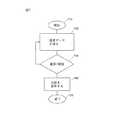
図7は、本発明の態様の高圧処理システム内の再循環ループ中を流れる高圧処理流体の温度をモニタする方法の流れ図を示す。操作700は710で開始し、ここで基板は、再循環ループの一部である処理チャンバ内に置くことができる。 FIG. 7 shows a flow diagram of a method for monitoring the temperature of the high pressure processing fluid flowing through the recirculation loop in the high pressure processing system of aspects of the present invention. Operation 700 begins at 710, where the substrate can be placed in a processing chamber that is part of a recirculation loop.
720では、高圧処理流体が再循環ループ中を流れ、再循環ループは、その中を高圧処理流体が通過する1つ以上のセンサアセンブリを含むことができる。各センサアセンブリは、高圧処理流体が流れる流路内またはその極めて近傍に取り付けられる熱電対のような熱センサを含むことができる。例えば、高圧処理流体は、本明細書に記載のように超臨界CO2と処理化学物質を含むことができる。例えば1つ以上のセンサアセンブリからの温度データを分析して、高圧処理流体の温度を決定することができる。At 720, the high pressure processing fluid flows through a recirculation loop, which can include one or more sensor assemblies through which the high pressure processing fluid passes. Each sensor assembly can include a thermal sensor such as a thermocouple mounted in or very close to the flow path through which the high pressure processing fluid flows. For example, the high pressure processing fluid can include supercritical CO2 and processing chemicals as described herein. For example, temperature data from one or more sensor assemblies can be analyzed to determine the temperature of the high pressure process fluid.
730では、温度データは閾値と比較される。温度データが閾値と実質的に等しい場合、操作700は分岐して720に戻り、図7に示すように続けることができる。温度データが閾値に等しくない場合、操作700は740に分岐する。740では、温度データが閾値より実質的に高いかまたは実質的に低い時、フォールト状態が確立される。例えば温度データが閾値に実質的に等しい場合、正常な/非フォールト状態が確立される。 At 730, the temperature data is compared to a threshold value. If the temperature data is substantially equal to the threshold, operation 700 branches back to 720 and can continue as shown in FIG. If the temperature data is not equal to the threshold, operation 700 branches to 740. At 740, a fault condition is established when the temperature data is substantially above or below the threshold. For example, if the temperature data is substantially equal to the threshold value, a normal / non-fault condition is established.
操作700は750で終わる。 Operation 700 ends at 750.
本発明の構成と操作原理の理解を容易にするために、詳細を含む具体例により本発明を説明したが、具体例およびその詳細へのかかる言及は、添付の請求の範囲を限定するものではない。本発明の精神と範囲とを逸脱することなく、例示した態様の修飾が可能であることは、当業者に明らかであろう。 The present invention has been described in terms of specific examples, including details, in order to facilitate an understanding of the organization and operating principles of the present invention, but such specific examples and such reference to details thereof are not intended to limit the scope of the appended claims. Absent. It will be apparent to those skilled in the art that modifications can be made to the illustrated embodiments without departing from the spirit and scope of the invention.
Claims (29)
Translated fromJapanesea.高圧処理チャンバと、高圧処理チャンバに連結された高圧再循環システムとを含む再循環ループであって;処理流体は再循環ループを通して(through)流れるもの;
b.再循環ループに連結され、再循環ループに流体を供給する手段を含む、高圧流体供給システム;
c.再循環ループに連結され、再循環ループに処理化学物質(process chemistry)を供給する手段を含む、処理化学物質供給システム;
d.再循環ループ中を通して流れる処理流体の温度をモニタするための、再循環ループに連結されたセンサアセンブリであって;且つ、該センサアセンブリが高圧で作動するように構成され;且つ、前記センサアセンブリが以下を含む:
i.センサ、センサに連結された本体、および本体に連結された電気接続手段を含むセンササブアセンブリ;
ii.先端部分、該先端部分に連結された移動(transition)部分、および、該移動部分に連結された環(annular ring)部分を有する保護シースであって;前記センササブアセンブリは、内部で保護シースに少なくとも部分的に連結され、前記センサは保護シースの先端部分内に取り付けられている;
iii.下記を含むグランド(gland)アセンブリ:
(1)前記保護シースの周囲(around)に配置されたガスケットであって;該ガスケットが第1の側および第2の側を含み;
(2)保護シースの周囲に配置された第1のシーリンググランドであって;該第1のシーリンググランドが、前記ガスケットの第1の側に取り外し可能(removably)に連結され;
(3)保護シースの周囲に配置された第2のシーリンググランドであって;該第2のシーリンググランドが、前記ガスケットの第2の側に取り外し可能に連結され;
(4)スレッドを有する第1のナットであって;該第1のナットが第1のシーリンググランドに取り外し可能に連結され;および
(5)スレッドを有する第2のナットであって;該第2のナットが第2のシーリンググランドに取り外し可能に連結され;且つ、該第1のナットおよび第2のナットが一緒にねじ締め(screwed)されて、該第1のグランドおよび第2のグランドがガスケットを圧するように押しつけられて(forcing)、前記グランドアセンブリをシールしているもの;および、
e.高圧処理チャンバ、再循環システム、高圧流体供給システム、処理化学物質供給システム、およびセンサアセンブリに連結されたコントローラーを含むシステム。A system for monitoring a processing fluid temperature in a high pressure processing system; the system includes:
a. A recirculation loop including a high pressure processing chamber and a high pressure recirculation system coupled to the high pressure processing chamber; the processing fluid flows through the recirculation loop;
b. A high pressure fluid supply system coupled to the recirculation loop and including means for supplying fluid to the recirculation loop;
c. A processing chemical supply system coupled to the recirculation loop and including means for supplying process chemistry to the recirculation loop;
d. A sensor assembly coupled to the recirculation loop for monitoring the temperature of the processing fluid flowing through the recirculation loop; and wherein the sensor assembly is configured to operate at a high pressure; Includes:
i. A sensor subassembly including a sensor, a body coupled to the sensor, and electrical connection means coupled to the body;
ii. A protective sheath having a tip portion, a transitionportion connected to the tip portion,and an annular ringportion connected to the moving portion ; the sensor subassembly is internally connected to the protective sheath At least partially coupled, the sensor being mounted within the distal portion of the protective sheath;
iii. Gland assembly including:
(1) a gasket disposed around the protective sheath; the gasket including a first side and a second side;
(2) a first sealing gland disposed around the protective sheath; wherein the first sealing gland is removably connected to the first side of the gasket;
(3) a second sealing gland disposed around the protective sheath; wherein the second sealing gland is removably coupled to the second side of the gasket;
(4) a first nut having a thread; wherein the first nut is removably coupled to a first sealing gland; and (5) a second nut having a thread; A nut is removably coupled to a second sealing gland; and the first nut and the second nut are screwed together so that the first gland and the second gland are gaskets. Forcing and sealing the gland assembly; and
e. A system including a high pressure processing chamber, a recirculation system, a high pressure fluid supply system, a processing chemical supply system, and a controller coupled to the sensor assembly.
高圧処理チャンバと、高圧処理チャンバに連結された高圧再循環システムとを含む再循環ループであって;処理流体は再循環ループを通して流れるもの;
再循環ループに連結され、再循環ループに流体を供給する手段を含む、高圧流体供給システム;
再循環ループに連結され、再循環ループに処理化学物質を供給する手段を含む、処理化学物質供給システム;
再循環ループを通して流れる処理流体の温度をモニタするための、再循環ループに連結されたセンサアセンブリであって;該センサアセンブリが以下を含むもの:
保護シース、保護シースに連結された第1のシーリンググランド、第1のシーリンググランドに取り外し可能に連結されたガスケット、ガスケットに取り外し可能に連結された第2のシーリンググランド、第1のシーリンググランドに取り外し可能に連結された第1のナット、第2のシーリンググランドと第1のナットに取り外し可能に連結された第2のナットを含むグランドアセンブリ;
センサ、センサに連結された本体、および本体に連結された電気接続手段を含むセンササブアセンブリであって;該センササブアセンブリは、内部で保護シースに連結されているもの;および
第2のシーリンググランドに連結された第1のセクションと、再循環ループにセンサアセンブリを連結する手段を含む第2のセクションとを有するT型フィッティングを含む流れアセンブリ;および
高圧処理チャンバ、再循環システム、高圧流体供給システム、処理化学物質供給システム、およびセンサアセンブリに連結されたコントローラーを含むシステムであって;該コントローラーは、センサアセンブリから処理流体の温度データを得る手段、温度データを閾値と比較する手段、温度データが閾値より実質的に大きい時または実質的に小さい時フォールト状態を作成する手段、および温度データが閾値にほぼ等しい時、非フォールト状態を作成する手段を含む。A system for monitoring process fluid temperature within a high pressure processing system; the system includes:
A recirculation loop including a high pressure processing chamber and a high pressure recirculation system coupled to the high pressure processing chamber; the processing fluid flows through the recirculation loop;
A high pressure fluid supply system coupled to the recirculation loop and including means for supplying fluid to the recirculation loop;
A treatment chemical supply system coupled to the recirculation loop and including means for supplying the treatment chemical to the recirculation loop;
A sensor assembly coupled to the recirculation loop for monitoring the temperature of the processing fluid flowing through the recirculation loop, the sensor assembly including:
Protective sheath, first sealing gland coupled to protective sheath, gasket removably coupled to first sealing gland, second sealing gland removably coupled to gasket, removed to first sealing gland A gland assembly including a first nut removably coupled, a second sealing gland and a second nut removably coupled to the first nut;
A sensor subassembly comprising a sensor, a body coupled to the sensor, and an electrical connection means coupled to the body; the sensor subassembly being coupled to a protective sheath therein; and a second sealing gland A flow assembly including a T-fitting having a first section coupled to the second section and a second section including means for coupling the sensor assembly to the recirculation loop; and a high pressure processing chamber, a recirculation system, a high pressure fluid supply system A process chemical supply system and a controller coupled to the sensor assembly; the controller comprising means for obtaining temperature data of the process fluid from the sensor assembly; means for comparing the temperature data to a threshold; When substantially greater than or below threshold When means for creating a fault condition, and temperature data are substantially equal to the threshold, including means for creating a non-fault state.
高圧処理チャンバと、高圧処理チャンバに連結された高圧再循環システムとを含む再循環ループであって;処理流体は再循環ループを通して流れるもの;
再循環ループに連結され、再循環ループに流体を供給する手段を含む、高圧流体供給システム;
再循環ループに連結され、再循環ループに処理化学物質を供給する手段を含む、処理化学物質供給システム;
再循環ループを通して流れる処理流体の温度をモニタするための、再循環ループに連結されたセンサアセンブリであって;該記センサアセンブリが以下を含む:
センサ、センサに連結された本体、本体に連結された電気接続手段、および保護シースを含むセンササブアセンブリであって;該センサと本体は、内部で保護シースに連結され、センサは保護シースの先端部分内に取り付けられているもの;
センササブアセンブリの一部をシールドするためのシーリング構造、ナットを連結するための保持表面、及び、センササブアセンブリの一部を側面から覆うように構成された合せ構造を有する第1のセクションと、再循環ループにセンサアセンブリを連結する手段を含む第2のセクションとを有するT型フィッティングを含む、流れアセンブリ;および
前記ナットが連結される合せ(mating)表面を有するシーリンググランド、シーリンググランドとT型フィッティングの前記シーリング構造とに取り外し可能に連結されたガスケット、シーリンググランドの前記合せ表面とT型フィッティングの前記保持(holding)表面に取り外し可能に連結された前記ナット、を含むグランドアセンブリ;および
高圧処理チャンバ、再循環システム、高圧流体供給システム、処理化学物質供給システム、およびセンサアセンブリに連結されたコントローラーを含むシステムであって;該コントローラーは、センサアセンブリから処理流体の温度データを得る手段、温度データを閾値と比較する手段、温度データが閾値より実質的に大きい時または実質的に小さい時フォールト状態を作成する手段、および温度データが閾値にほぼ等しい時、非フォールト状態を作成する手段を含む。A system for monitoring process fluid temperature within a high pressure processing system; the system includes:
A recirculation loop including a high pressure processing chamber and a high pressure recirculation system coupled to the high pressure processing chamber; the processing fluid flows through the recirculation loop;
A high pressure fluid supply system coupled to the recirculation loop and including means for supplying fluid to the recirculation loop;
A treatment chemical supply system coupled to the recirculation loop and including means for supplying the treatment chemical to the recirculation loop;
A sensor assembly coupled to the recirculation loop for monitoring the temperature of the processing fluid flowing through the recirculation loop; the sensor assembly includes:
A sensor subassembly including a sensor, a body coupled to the sensor, an electrical connection means coupled to the body, and a protective sheath; the sensor and the body are internally coupled to the protective sheath, the sensor being a tip of the protective sheath Installed in the part;
A first section having a sealing structure for shielding a portion of the sensor subassembly, a retaining surface for coupling the nut, and a mating structure configuredto cover a portion of the sensor subassemblyfrom the side ; A flow assembly including a T-shaped fitting having a second section including means for coupling the sensor assembly to the recirculation loop; and a sealing gland having a mating surface to which the nut is coupled, the sealing gland and the T-shaped A gland assembly including a gasket removably coupled to the sealing structure of the fitting, the mating surface of the sealing gland and the nut removably coupled to the holding surface of the T-fitting; and high pressure processing Chamber, recirculation system, high pressure flow A system including a supply system, a process chemical supply system, and a controller coupled to the sensor assembly; the controller obtaining means for obtaining temperature data of the process fluid from the sensor assembly; means for comparing the temperature data to a threshold; temperature Means for creating a fault condition when the data is substantially greater than or substantially less than the threshold, and means for creating a non-fault condition when the temperature data is approximately equal to the threshold.
高圧処理チャンバと、高圧処理チャンバに連結された高圧再循環システムとを含む再循環ループであって;処理流体は再循環ループを通して流れるもの;
再循環ループに連結され、再循環ループに流体を供給する手段を含む、高圧流体供給システム;
再循環ループに連結され、再循環ループに処理化学物質を供給する手段を含む、処理化学物質供給システム;
再循環ループを通して流れる処理流体の温度をモニタするための、再循環ループに連結されたセンサアセンブリであって;該センサアセンブリが以下を含むもの:
センサ、センサに連結された本体、本体に連結された電気接続手段、およびシーリング構造と合せ表面を含む保護シースを含むセンササブアセンブリであって;該センサと本体は、内部で保護シースに連結され、センサは保護シースの先端部分内に取り付けられているもの;
センササブアセンブリの一部をシールドするためのシーリング構造、ナットを連結するための保持表面、及び、センササブアセンブリの一部を側面から覆うように構成された合せ構造を有する第1のセクションと、再循環ループにセンサアセンブリを連結する手段を含む第2のセクションと、を含むT型フィッティングを含む、流れアセンブリ;および
前記ナットを連結するための合せ表面を有するシーリンググランド、シーリンググランドとT型フィッティングの前記シーリング構造とに取り外し可能に連結されたガスケット、シーリンググランドの前記合せ表面とT型フィッティングの前記保持表面とに取り外し可能に連結された前記ナットを含むグランドアセンブリ;および
高圧処理チャンバ、再循環システム、高圧流体供給システム、処理化学物質供給システム、およびセンサアセンブリに連結されたコントローラーを含むシステムであって;該コントローラーは、センサアセンブリから処理流体の温度データを得る手段、温度データを閾値と比較する手段、温度データが閾値より実質的に大きい時または実質的に小さい時フォールト状態を構成する手段、および温度データが閾値にほぼ等しい時、非フォールト状態を作成する手段を含む。A system for monitoring process fluid temperature within a high pressure processing system; the system includes:
A recirculation loop including a high pressure processing chamber and a high pressure recirculation system coupled to the high pressure processing chamber; the processing fluid flows through the recirculation loop;
A high pressure fluid supply system coupled to the recirculation loop and including means for supplying fluid to the recirculation loop;
A treatment chemical supply system coupled to the recirculation loop and including means for supplying the treatment chemical to the recirculation loop;
A sensor assembly coupled to the recirculation loop for monitoring the temperature of the processing fluid flowing through the recirculation loop, the sensor assembly including:
A sensor subassembly including a sensor, a body coupled to the sensor, an electrical connection means coupled to the body, and a protective sheath including a sealing structure and a mating surface; the sensor and the body are coupled to the protective sheath internally The sensor is mounted in the tip of the protective sheath;
A first section having a sealing structure for shielding a portion of the sensor subassembly, a retaining surface for coupling the nut, and a mating structure configuredto cover a portion of the sensor subassemblyfrom the side ; A second section including means for connecting the sensor assembly to the recirculation loop; and a T assembly including the flow assembly; and a sealing gland having a mating surface for connecting the nut, the sealing gland and the T fitting A gasket assembly removably coupled to the sealing structure of the gland; a gland assembly including the nut removably coupled to the mating surface of the sealing gland and the holding surface of the T-fitting; and a high pressure processing chamber, recirculation System, high-pressure fluid supply system A process chemical supply system and a controller coupled to the sensor assembly; the controller comprising means for obtaining temperature data of the process fluid from the sensor assembly; means for comparing the temperature data to a threshold; Means for configuring a fault condition when substantially greater than or substantially less than a threshold, and means for creating a non-fault condition when the temperature data is approximately equal to the threshold.
a.高圧処理チャンバと、高圧処理チャンバに連結された高圧再循環システムとを含む再循環ループであって;処理流体は再循環ループを通して流れるもの;
b.再循環ループに連結され、再循環ループに流体を供給する手段を含む、高圧流体供給システム;
c.再循環ループに連結され、再循環ループに処理化学物質を供給する手段を含む、処理化学物質供給システム;
d.再循環ループを通して流れる処理流体の温度をモニタするための、再循環ループに連結されたセンサアセンブリであって;該センサアセンブリ高圧で作動するように構成され;且つ、前記センサアセンブリが以下を含む:
i.センサ、センサに連結された本体、および本体に連結された電気接続手段を含むセンササブアセンブリ;
ii.先端部分、該先端部分に連結された移動部分、および前記移動部分に連結された環部分を有する保護シースであって;前記センササブアセンブリは、内部で保護シースに少なくとも部分的に連結され、前記センサは保護シースの先端部分内に取り付けられているもの;
iii.下記を含むグランドアセンブリ:
(1)前記保護シースの周囲に配置されたガスケットであって;該ガスケットが第1の側および第2の側を含み;
(2)保護シースの周囲に配置された第1のシーリンググランドであって;該第1のシーリンググランドが、前記ガスケットの第1の側に取り外し可能に連結され;
(3)保護シースの周囲に配置された第2のシーリンググランドであって;該第2のシーリンググランドが、前記ガスケットの第2の側に取り外し可能に連結され;
(4)スレッドを有する第1のナットであって;該第1のナットが第1のシーリンググランドに取り外し可能に連結され;および
(5)スレッドを有する第2のナットであって;該第2のナットが第2のシーリンググランドに取り外し可能に連結され;且つ、該第2のナットおよび第1のナットがねじ締めされて、該第1のグランドおよび第2のグランドがガスケットを圧するように押しつけられて、前記グランドアセンブリをシールしているもの;および、
iv.高圧処理チャンバ、再循環システム、高圧流体供給システム、処理化学物質供給システム、およびセンサアセンブリに連結されたコントローラーを含むシステムであって;該コントローラーは、センサアセンブリから処理流体の温度データを得る手段、温度データを閾値と比較する手段、温度データが閾値より実質的に大きい時または実質的に小さい時フォールト状態を構成する手段、および温度データが閾値にほぼ等しい時、非フォールト状態を作成する手段を含む。A system for monitoring process fluid temperature within a high pressure processing system; the system includes:
a. A recirculation loop including a high pressure processing chamber and a high pressure recirculation system coupled to the high pressure processing chamber; the processing fluid flows through the recirculation loop;
b. A high pressure fluid supply system coupled to the recirculation loop and including means for supplying fluid to the recirculation loop;
c. A treatment chemical supply system coupled to the recirculation loop and including means for supplying the treatment chemical to the recirculation loop;
d. A sensor assembly coupled to the recirculation loop for monitoring the temperature of the processing fluid flowing through the recirculation loop; configured to operate at a high pressure on the sensor assembly; and the sensor assembly includes:
i. A sensor subassembly including a sensor, a body coupled to the sensor, and electrical connection means coupled to the body;
ii. A protective sheath having a tip portion,a moving portionconnected to the tip portion,and a ring portionconnected to the moving portion ; wherein the sensor subassembly is at least partially connected to the protective sheath; The sensor is mounted in the tip of the protective sheath;
iii. Gland assembly including:
(1) a gasket disposed around the protective sheath; the gasket including a first side and a second side;
(2) a first sealing gland disposed around the protective sheath; wherein the first sealing gland is removably coupled to the first side of the gasket;
(3) a second sealing gland disposed around the protective sheath; wherein the second sealing gland is removably coupled to the second side of the gasket;
(4) a first nut having a thread; wherein the first nut is removably coupled to a first sealing gland; and (5) a second nut having a thread; A nut is removably coupled to a second sealing gland; and the second nut and the first nut are screwed together to press the first gland and the second gland against the gasket. And sealing the gland assembly; and
iv. A system including a high pressure processing chamber, a recirculation system, a high pressure fluid supply system, a processing chemical supply system, and a controller coupled to the sensor assembly; wherein the controller obtains processing fluid temperature data from the sensor assembly; Means for comparing temperature data with a threshold, means for forming a fault condition when the temperature data is substantially greater than or substantially less than the threshold, and means for creating a non-fault condition when the temperature data is approximately equal to the threshold. Including.
高圧処理チャンバと、高圧処理チャンバに連結された高圧再循環システムとを含む再循環ループであって;処理流体は再循環ループを通して流れるもの;
再循環ループに連結され、再循環ループに流体を供給する手段を含む、高圧流体供給システム;
再循環ループに連結され、再循環ループに処理化学物質を供給する手段を含む、処理化学物質供給システム;
再循環ループを通して流れる処理流体の温度をモニタするための、再循環ループに連結されたセンサアセンブリであって;該センサアセンブリが以下を含むもの:
第1のシーリンググランド、第1のシーリンググランドに取り外し可能に連結されたガスケット、ガスケットに取り外し可能に連結された第2のシーリンググランド、第1のシーリンググランドに取り外し可能に連結された第1のナット、第2のシーリンググランドと第1のナットに取り外し可能に連結された第2のナットを含むグランドアセンブリ;
センサ、センサに連結された本体、本体に連結された電気接続手段、および第1のシーリンググランドに連結された保護シースを含むセンササブアセンブリであって;該センサと本体は、内部で保護シースに連結されているもの;および
第2のシーリンググランドに連結された第1のセクションと、再循環ループにセンサアセンブリを連結する手段を含む第2のセクションとを有するT型フィッティングを含む流れアセンブリ;および
高圧処理チャンバ、再循環システム、高圧流体供給システム、処理化学物質供給システム、およびセンサアセンブリに連結されたコントローラーを含むシステムであって;該コントローラーは、センサアセンブリから処理流体の温度データを得る手段、温度データを閾値と比較する手段、温度データが閾値より実質的に大きい時または実質的に小さい時フォールト状態を構成する手段、および温度データが閾値にほぼ等しい時、非フォールト状態を作成する手段を含む。A system for monitoring process fluid temperature within a high pressure processing system; the system includes:
A recirculation loop including a high pressure processing chamber and a high pressure recirculation system coupled to the high pressure processing chamber; the processing fluid flows through the recirculation loop;
A high pressure fluid supply system coupled to the recirculation loop and including means for supplying fluid to the recirculation loop;
A treatment chemical supply system coupled to the recirculation loop and including means for supplying the treatment chemical to the recirculation loop;
A sensor assembly coupled to the recirculation loop for monitoring the temperature of the processing fluid flowing through the recirculation loop, the sensor assembly including:
A first sealing gland, a gasket removably coupled to the first sealing gland, a second sealing gland removably coupled to the gasket, and a first nut removably coupled to the first sealing gland A gland assembly including a second sealing gland and a second nut removably coupled to the first nut;
A sensor subassembly including a sensor, a body coupled to the sensor, an electrical connection means coupled to the body, and a protective sheath coupled to a first sealing ground; the sensor and the body internally to the protective sheath And a flow assembly including a T-shaped fitting having a first section coupled to a second sealing gland and a second section including means for coupling the sensor assembly to the recirculation loop; and A system including a high pressure processing chamber, a recirculation system, a high pressure fluid supply system, a processing chemical supply system, and a controller coupled to the sensor assembly; wherein the controller obtains processing fluid temperature data from the sensor assembly; Means to compare temperature data with threshold, temperature data is threshold Ri when means constituting a fault condition when the time is substantially greater or substantially less, and the temperature data is substantially equal to the threshold, including means for creating a non-fault state.
Applications Claiming Priority (2)
| Application Number | Priority Date | Filing Date | Title |
|---|---|---|---|
| US11/092,232 | 2005-03-28 | ||
| US11/092,232US7380984B2 (en) | 2005-03-28 | 2005-03-28 | Process flow thermocouple |
Publications (3)
| Publication Number | Publication Date |
|---|---|
| JP2006284574A JP2006284574A (en) | 2006-10-19 |
| JP2006284574A5 JP2006284574A5 (en) | 2009-04-30 |
| JP4987329B2true JP4987329B2 (en) | 2012-07-25 |
Family
ID=37035125
Family Applications (1)
| Application Number | Title | Priority Date | Filing Date |
|---|---|---|---|
| JP2006083006AExpired - Fee RelatedJP4987329B2 (en) | 2005-03-28 | 2006-03-24 | Process flow thermocouple |
Country Status (2)
| Country | Link |
|---|---|
| US (1) | US7380984B2 (en) |
| JP (1) | JP4987329B2 (en) |
Families Citing this family (28)
| Publication number | Priority date | Publication date | Assignee | Title |
|---|---|---|---|---|
| JP4188287B2 (en)* | 2004-07-15 | 2008-11-26 | 三井金属鉱業株式会社 | Thermal sensor and measuring apparatus using the same |
| FR2895506B1 (en)* | 2005-12-28 | 2008-02-01 | Intuiskin Soc Par Actions Simp | MINIATURIZED MEASURING DEVICE |
| US20070268955A1 (en)* | 2006-05-17 | 2007-11-22 | Pohl Hermann K | Thermal fluid device with remote temperature indicator |
| DE102006034181B3 (en)* | 2006-07-24 | 2008-04-03 | Siemens Ag | temperature sensor |
| KR100829923B1 (en)* | 2006-08-30 | 2008-05-16 | 세메스 주식회사 | Spin head and substrate processing method using same |
| JP5097496B2 (en)* | 2007-09-28 | 2012-12-12 | 東レエンジニアリング株式会社 | Temperature measuring device |
| US9179336B2 (en) | 2013-02-19 | 2015-11-03 | Mimosa Networks, Inc. | WiFi management interface for microwave radio and reset to factory defaults |
| US9930592B2 (en) | 2013-02-19 | 2018-03-27 | Mimosa Networks, Inc. | Systems and methods for directing mobile device connectivity |
| US9362629B2 (en) | 2013-03-06 | 2016-06-07 | Mimosa Networks, Inc. | Enclosure for radio, parabolic dish antenna, and side lobe shields |
| WO2014137370A1 (en)* | 2013-03-06 | 2014-09-12 | Mimosa Networks, Inc. | Waterproof apparatus for cables and cable interfaces |
| US10742275B2 (en) | 2013-03-07 | 2020-08-11 | Mimosa Networks, Inc. | Quad-sector antenna using circular polarization |
| US9191081B2 (en) | 2013-03-08 | 2015-11-17 | Mimosa Networks, Inc. | System and method for dual-band backhaul radio |
| US9295103B2 (en) | 2013-05-30 | 2016-03-22 | Mimosa Networks, Inc. | Wireless access points providing hybrid 802.11 and scheduled priority access communications |
| US10938110B2 (en) | 2013-06-28 | 2021-03-02 | Mimosa Networks, Inc. | Ellipticity reduction in circularly polarized array antennas |
| WO2015104241A1 (en)* | 2014-01-08 | 2015-07-16 | Vesuvius Group, Sa | Optical pyrometer |
| US9001689B1 (en) | 2014-01-24 | 2015-04-07 | Mimosa Networks, Inc. | Channel optimization in half duplex communications systems |
| US9780892B2 (en) | 2014-03-05 | 2017-10-03 | Mimosa Networks, Inc. | System and method for aligning a radio using an automated audio guide |
| US9998246B2 (en) | 2014-03-13 | 2018-06-12 | Mimosa Networks, Inc. | Simultaneous transmission on shared channel |
| US10958332B2 (en) | 2014-09-08 | 2021-03-23 | Mimosa Networks, Inc. | Wi-Fi hotspot repeater |
| USD752566S1 (en) | 2014-09-12 | 2016-03-29 | Mimosa Networks, Inc. | Wireless repeater |
| US10161639B2 (en)* | 2015-03-10 | 2018-12-25 | Joseph Copeland | Heat transfer apparatus and heat transfer system for masonry heater |
| US10044338B2 (en) | 2015-10-15 | 2018-08-07 | Lam Research Corporation | Mutually induced filters |
| WO2017123558A1 (en) | 2016-01-11 | 2017-07-20 | Mimosa Networks, Inc. | Printed circuit board mounted antenna and waveguide interface |
| US11251539B2 (en) | 2016-07-29 | 2022-02-15 | Airspan Ip Holdco Llc | Multi-band access point antenna array |
| US10511074B2 (en) | 2018-01-05 | 2019-12-17 | Mimosa Networks, Inc. | Higher signal isolation solutions for printed circuit board mounted antenna and waveguide interface |
| US11069986B2 (en) | 2018-03-02 | 2021-07-20 | Airspan Ip Holdco Llc | Omni-directional orthogonally-polarized antenna system for MIMO applications |
| US11289821B2 (en) | 2018-09-11 | 2022-03-29 | Air Span Ip Holdco Llc | Sector antenna systems and methods for providing high gain and high side-lobe rejection |
| JP7197396B2 (en)* | 2019-02-06 | 2022-12-27 | 東京エレクトロン株式会社 | SUBSTRATE PROCESSING APPARATUS AND SUBSTRATE PROCESSING METHOD |
Family Cites Families (322)
| Publication number | Priority date | Publication date | Assignee | Title |
|---|---|---|---|---|
| US2625886A (en) | 1947-08-21 | 1953-01-20 | American Brake Shoe Co | Pump |
| US2617719A (en) | 1950-12-29 | 1952-11-11 | Stanolind Oil & Gas Co | Cleaning porous media |
| US2873597A (en) | 1955-08-08 | 1959-02-17 | Victor T Fahringer | Apparatus for sealing a pressure vessel |
| US2981106A (en)* | 1957-10-08 | 1961-04-25 | Lewis Eng Co | Pyrometer bulb |
| FR1499491A (en) | 1966-09-30 | 1967-10-27 | Albert Handtmann Metallgiesser | Pass-through and shut-off valve, in particular for drinks |
| US3521765A (en) | 1967-10-31 | 1970-07-28 | Western Electric Co | Closed-end machine for processing articles in a controlled atmosphere |
| US3681171A (en) | 1968-08-23 | 1972-08-01 | Hitachi Ltd | Apparatus for producing a multilayer printed circuit plate assembly |
| US3623627A (en) | 1969-08-22 | 1971-11-30 | Hunt Co Rodney | Door construction for a pressure vessel |
| US4008049A (en)* | 1970-07-09 | 1977-02-15 | Dart Industries Inc. | Apparatus for controlling operational parameters in polymerization equipment |
| US3744660A (en) | 1970-12-30 | 1973-07-10 | Combustion Eng | Shield for nuclear reactor vessel |
| US3968885A (en) | 1973-06-29 | 1976-07-13 | International Business Machines Corporation | Method and apparatus for handling workpieces |
| FR2281562A1 (en)* | 1974-08-09 | 1976-03-05 | Otto & Co Gmbh Dr C | PROBE LOCATED IN A HIGH PRESSURE CHAMBER |
| US4341592A (en) | 1975-08-04 | 1982-07-27 | Texas Instruments Incorporated | Method for removing photoresist layer from substrate by ozone treatment |
| US4029517A (en) | 1976-03-01 | 1977-06-14 | Autosonics Inc. | Vapor degreasing system having a divider wall between upper and lower vapor zone portions |
| US4091643A (en) | 1976-05-14 | 1978-05-30 | Ama Universal S.P.A. | Circuit for the recovery of solvent vapor evolved in the course of a cleaning cycle in dry-cleaning machines or plants, and for the de-pressurizing of such machines |
| GB1594935A (en) | 1976-11-01 | 1981-08-05 | Gen Descaling Co Ltd | Closure for pipe or pressure vessel and seal therefor |
| US4145161A (en) | 1977-08-10 | 1979-03-20 | Standard Oil Company (Indiana) | Speed control |
| DE2741024A1 (en) | 1977-09-12 | 1979-03-22 | Wilms Gmbh | DIAPHRAGM PUMP |
| JPS5448172A (en) | 1977-09-24 | 1979-04-16 | Tokyo Ouka Kougiyou Kk | Plasma reaction processor |
| GB2058247B (en)* | 1979-09-10 | 1983-02-16 | Redland Automation Ltd | Stuffing box |
| US4367140A (en) | 1979-11-05 | 1983-01-04 | Sykes Ocean Water Ltd. | Reverse osmosis liquid purification apparatus |
| DE3110341C2 (en) | 1980-03-19 | 1983-11-17 | Hitachi, Ltd., Tokyo | Method and apparatus for aligning a thin substrate in the image plane of a copier |
| JPS56142629A (en) | 1980-04-09 | 1981-11-07 | Nec Corp | Vacuum device |
| US4355937A (en) | 1980-12-24 | 1982-10-26 | International Business Machines Corporation | Low shock transmissive antechamber seal mechanisms for vacuum chamber type semi-conductor wafer electron beam writing apparatus |
| US4316750A (en) | 1981-01-16 | 1982-02-23 | Western Electric Company, Inc. | Apparatus and method for cleaning a flux station of a soldering system |
| DE3112434A1 (en) | 1981-03-28 | 1982-10-07 | Depa GmbH, 4000 Düsseldorf | PNEUMATIC DIAPHRAGM PUMP |
| JPS6117151Y2 (en) | 1981-05-19 | 1986-05-26 | ||
| US4682937A (en) | 1981-11-12 | 1987-07-28 | The Coca-Cola Company | Double-acting diaphragm pump and reversing mechanism therefor |
| DE3145815C2 (en) | 1981-11-19 | 1984-08-09 | AGA Gas GmbH, 2102 Hamburg | Process for removing peelable layers of material from coated objects, |
| US4522788A (en) | 1982-03-05 | 1985-06-11 | Leco Corporation | Proximate analyzer |
| US4426388A (en) | 1982-04-02 | 1984-01-17 | Merck & Co., Inc. | 5-Benzothiazolesulfonamide derivatives for the topical treatment of elevated intraocular pressure |
| NL8202518A (en) | 1982-06-22 | 1984-01-16 | Tno | METHOD AND APPARATUS FOR COUNTERFLOW TREATMENT OF SUSPENDED PARTICLES WITH A LIQUID |
| DE3238768A1 (en) | 1982-10-20 | 1984-04-26 | Kurt Wolf & Co Kg, 7547 Wildbad | COOKING VESSEL FROM COOKER AND LID, ESPECIALLY STEAM PRESSURE COOKER |
| FR2536433A1 (en) | 1982-11-19 | 1984-05-25 | Privat Michel | METHOD AND APPARATUS FOR CLEANING AND DECONTAMINATING PARTICULARLY CLOTHING, ESPECIALLY CLOTHES CONTAMINATED WITH RADIOACTIVE PARTICLES |
| US4626509A (en) | 1983-07-11 | 1986-12-02 | Data Packaging Corp. | Culture media transfer assembly |
| US4865061A (en) | 1983-07-22 | 1989-09-12 | Quadrex Hps, Inc. | Decontamination apparatus for chemically and/or radioactively contaminated tools and equipment |
| US4549467A (en) | 1983-08-03 | 1985-10-29 | Wilden Pump & Engineering Co. | Actuator valve |
| DE3341860C2 (en)* | 1983-11-19 | 1985-09-19 | Hydrotechnik Gmbh, 6250 Limburg | Measuring coupling for fluid systems |
| GB8332394D0 (en) | 1983-12-05 | 1984-01-11 | Pilkington Brothers Plc | Coating apparatus |
| JPS60238479A (en) | 1984-05-10 | 1985-11-27 | Anelva Corp | Vacuum thin film processing equipment |
| JPS60246635A (en) | 1984-05-22 | 1985-12-06 | Anelva Corp | Automatic substrate processing equipment |
| US4960140A (en) | 1984-11-30 | 1990-10-02 | Ishijima Industrial Co., Ltd. | Washing arrangement for and method of washing lead frames |
| US4693777A (en) | 1984-11-30 | 1987-09-15 | Kabushiki Kaisha Toshiba | Apparatus for producing semiconductor devices |
| US4618769A (en) | 1985-01-04 | 1986-10-21 | The United States Of America As Represented By The United States Department Of Energy | Liquid chromatography/Fourier transform IR spectrometry interface flow cell |
| JPS61231166A (en) | 1985-04-08 | 1986-10-15 | Hitachi Ltd | Complex ultra-high vacuum equipment |
| US4788043A (en) | 1985-04-17 | 1988-11-29 | Tokuyama Soda Kabushiki Kaisha | Process for washing semiconductor substrate with organic solvent |
| DE3513749C1 (en)* | 1985-04-17 | 1986-09-04 | Hydrotechnik Gmbh | Sensor for fluidic systems |
| US4848927A (en)* | 1985-05-13 | 1989-07-18 | Daily Instruments, Inc. | Thermocouple containment chamber |
| US4778356A (en) | 1985-06-11 | 1988-10-18 | Hicks Cecil T | Diaphragm pump |
| US4749440A (en) | 1985-08-28 | 1988-06-07 | Fsi Corporation | Gaseous process and apparatus for removing films from substrates |
| US5044871A (en) | 1985-10-24 | 1991-09-03 | Texas Instruments Incorporated | Integrated circuit processing system |
| JPS62125619A (en) | 1985-11-27 | 1987-06-06 | Hitachi Ltd | cleaning equipment |
| US4827867A (en) | 1985-11-28 | 1989-05-09 | Daikin Industries, Ltd. | Resist developing apparatus |
| JPS62111442U (en) | 1985-12-28 | 1987-07-16 | ||
| DE3608783A1 (en) | 1986-03-15 | 1987-09-17 | Telefunken Electronic Gmbh | Gas-phase epitaxial method and apparatus for carrying it out |
| CA1287594C (en) | 1986-04-04 | 1991-08-13 | Miroslav Eror | Method and apparatus for handling and processing wafer like materials |
| US4670126A (en) | 1986-04-28 | 1987-06-02 | Varian Associates, Inc. | Sputter module for modular wafer processing system |
| GB8709064D0 (en) | 1986-04-28 | 1987-05-20 | Varian Associates | Wafer handling arm |
| US4917556A (en) | 1986-04-28 | 1990-04-17 | Varian Associates, Inc. | Modular wafer transport and processing system |
| WO1987007309A1 (en) | 1986-05-19 | 1987-12-03 | Novellus Systems, Inc. | Deposition apparatus with automatic cleaning means and method of use |
| JPS63252439A (en) | 1986-12-19 | 1988-10-19 | アプライド マテリアルズインコーポレーテッド | Multi-chamber integrated processing system |
| US4951601A (en) | 1986-12-19 | 1990-08-28 | Applied Materials, Inc. | Multi-chamber integrated process system |
| JPS63157870A (en) | 1986-12-19 | 1988-06-30 | Anelva Corp | Substrate treatment device |
| US5882165A (en) | 1986-12-19 | 1999-03-16 | Applied Materials, Inc. | Multiple chamber integrated process system |
| JPS63256326A (en) | 1987-04-15 | 1988-10-24 | Hitachi Ltd | Vacuum chuck and its manufacturing method |
| JPS63179530U (en) | 1987-05-14 | 1988-11-21 | ||
| JPS63303059A (en) | 1987-05-30 | 1988-12-09 | Tokuda Seisakusho Ltd | Vacuum treatment equipment |
| US4924892A (en) | 1987-07-28 | 1990-05-15 | Mazda Motor Corporation | Painting truck washing system |
| DE3725565A1 (en) | 1987-08-01 | 1989-02-16 | Peter Weil | METHOD AND SYSTEM FOR DE-PAINTING OBJECTS WITH A SUBMERSIBLE CONTAINER WITH SOLVENT |
| US5105556A (en) | 1987-08-12 | 1992-04-21 | Hitachi, Ltd. | Vapor washing process and apparatus |
| US4838476A (en) | 1987-11-12 | 1989-06-13 | Fluocon Technologies Inc. | Vapour phase treatment process and apparatus |
| JPH0417333Y2 (en) | 1987-12-22 | 1992-04-17 | ||
| US4789077A (en) | 1988-02-24 | 1988-12-06 | Public Service Electric & Gas Company | Closure apparatus for a high pressure vessel |
| US4823976A (en) | 1988-05-04 | 1989-04-25 | The United States Of America As Represented By The Administrator Of The National Aeronautics And Space Administration | Quick actuating closure |
| US5224504A (en) | 1988-05-25 | 1993-07-06 | Semitool, Inc. | Single wafer processor |
| US5185296A (en) | 1988-07-26 | 1993-02-09 | Matsushita Electric Industrial Co., Ltd. | Method for forming a dielectric thin film or its pattern of high accuracy on a substrate |
| US5051135A (en) | 1989-01-30 | 1991-09-24 | Kabushiki Kaisha Tiyoda Seisakusho | Cleaning method using a solvent while preventing discharge of solvent vapors to the environment |
| JPH02209729A (en) | 1989-02-09 | 1990-08-21 | Matsushita Electric Ind Co Ltd | Manufacture of semiconductor device and apparatus for removing foreign substance |
| CA2027550C (en) | 1989-02-16 | 1995-12-26 | Janusz B. Pawliszyn | Apparatus and method for delivering supercritical fluid |
| JPH0724679Y2 (en) | 1989-02-22 | 1995-06-05 | エヌ・オー・ケー・メグラスティック株式会社 | Torsional damper |
| US4879431A (en) | 1989-03-09 | 1989-11-07 | Biomedical Research And Development Laboratories, Inc. | Tubeless cell harvester |
| US5169296A (en) | 1989-03-10 | 1992-12-08 | Wilden James K | Air driven double diaphragm pump |
| US5213485A (en) | 1989-03-10 | 1993-05-25 | Wilden James K | Air driven double diaphragm pump |
| JPH02122520U (en) | 1989-03-17 | 1990-10-08 | ||
| DE3914065A1 (en) | 1989-04-28 | 1990-10-31 | Leybold Ag | DEVICE FOR CARRYING OUT PLASMA ETCHING PROCESSES |
| US5288333A (en) | 1989-05-06 | 1994-02-22 | Dainippon Screen Mfg. Co., Ltd. | Wafer cleaning method and apparatus therefore |
| US5186718A (en) | 1989-05-19 | 1993-02-16 | Applied Materials, Inc. | Staged-vacuum wafer processing system and method |
| JPH02148841U (en) | 1989-05-19 | 1990-12-18 | ||
| US5062770A (en) | 1989-08-11 | 1991-11-05 | Systems Chemistry, Inc. | Fluid pumping apparatus and system with leak detection and containment |
| DE3926577A1 (en) | 1989-08-11 | 1991-02-14 | Leybold Ag | VACUUM PUMP WITH A ROTOR AND ROTOR BEARINGS OPERATED WITH VACUUM |
| US4983223A (en) | 1989-10-24 | 1991-01-08 | Chenpatents | Apparatus and method for reducing solvent vapor losses |
| US5226441A (en) | 1989-11-13 | 1993-07-13 | Cmb Industries | Backflow preventor with adjustable outflow direction |
| US5169408A (en) | 1990-01-26 | 1992-12-08 | Fsi International, Inc. | Apparatus for wafer processing with in situ rinse |
| JPH06500427A (en) | 1990-02-16 | 1994-01-13 | ボック、エドワード | Improved equipment for wafer transport and processing |
| US5186594A (en) | 1990-04-19 | 1993-02-16 | Applied Materials, Inc. | Dual cassette load lock |
| US5217043A (en) | 1990-04-19 | 1993-06-08 | Milic Novakovic | Control valve |
| DE69103316T2 (en) | 1990-04-20 | 1995-04-27 | Applied Materials Inc | Device and method for slit valve. |
| EP0456426B1 (en) | 1990-05-07 | 2004-09-15 | Canon Kabushiki Kaisha | Vacuum type wafer holder |
| US5370741A (en) | 1990-05-15 | 1994-12-06 | Semitool, Inc. | Dynamic semiconductor wafer processing using homogeneous chemical vapors |
| DE4018464A1 (en) | 1990-06-08 | 1991-12-12 | Ott Kg Lewa | DIAPHRAGM FOR A HYDRAULICALLY DRIVED DIAPHRAGM PUMP |
| US5071485A (en) | 1990-09-11 | 1991-12-10 | Fusion Systems Corporation | Method for photoresist stripping using reverse flow |
| US5236669A (en) | 1990-09-12 | 1993-08-17 | E. I. Du Pont De Nemours And Company | Pressure vessel |
| US5167716A (en) | 1990-09-28 | 1992-12-01 | Gasonics, Inc. | Method and apparatus for batch processing a semiconductor wafer |
| DE4106180A1 (en) | 1990-10-08 | 1992-04-09 | Dirk Dipl Ing Budde | DOUBLE DIAPHRAGM PUMP |
| US5306350A (en) | 1990-12-21 | 1994-04-26 | Union Carbide Chemicals & Plastics Technology Corporation | Methods for cleaning apparatus using compressed fluids |
| US5143103A (en) | 1991-01-04 | 1992-09-01 | International Business Machines Corporation | Apparatus for cleaning and drying workpieces |
| AT395951B (en) | 1991-02-19 | 1993-04-26 | Union Ind Compr Gase Gmbh | CLEANING OF WORKPIECES WITH ORGANIC RESIDUES |
| CH684402A5 (en) | 1991-03-04 | 1994-09-15 | Xorella Ag Wettingen | Device for sliding and pivoting of a container-closure. |
| JPH04284648A (en) | 1991-03-14 | 1992-10-09 | Fujitsu Ltd | Wafer holding dry-chuck rubber |
| US5259731A (en) | 1991-04-23 | 1993-11-09 | Dhindsa Jasbir S | Multiple reciprocating pump system |
| US5195878A (en) | 1991-05-20 | 1993-03-23 | Hytec Flow Systems | Air-operated high-temperature corrosive liquid pump |
| US5243821A (en) | 1991-06-24 | 1993-09-14 | Air Products And Chemicals, Inc. | Method and apparatus for delivering a continuous quantity of gas over a wide range of flow rates |
| US5197800A (en) | 1991-06-28 | 1993-03-30 | Nordson Corporation | Method for forming coating material formulations substantially comprised of a saturated resin rich phase |
| DE9109308U1 (en)* | 1991-07-27 | 1992-11-26 | Hoechst Ag, 65929 Frankfurt | Temperature measuring device |
| US5251776A (en) | 1991-08-12 | 1993-10-12 | H. William Morgan, Jr. | Pressure vessel |
| JP3040212B2 (en) | 1991-09-05 | 2000-05-15 | 株式会社東芝 | Vapor phase growth equipment |
| DE9112761U1 (en) | 1991-10-14 | 1992-04-09 | Krones Ag Hermann Kronseder Maschinenfabrik, 8402 Neutraubling | Vessel sealing machine |
| US5221019A (en) | 1991-11-07 | 1993-06-22 | Hahn & Clay | Remotely operable vessel cover positioner |
| US5190373A (en) | 1991-12-24 | 1993-03-02 | Union Carbide Chemicals & Plastics Technology Corporation | Method, apparatus, and article for forming a heated, pressurized mixture of fluids |
| US5240390A (en) | 1992-03-27 | 1993-08-31 | Graco Inc. | Air valve actuator for reciprocable machine |
| JP2750554B2 (en) | 1992-03-31 | 1998-05-13 | 日本電信電話株式会社 | Vacuum suction device |
| US5252041A (en) | 1992-04-30 | 1993-10-12 | Dorr-Oliver Incorporated | Automatic control system for diaphragm pumps |
| US5404894A (en) | 1992-05-20 | 1995-04-11 | Tokyo Electron Kabushiki Kaisha | Conveyor apparatus |
| US5313965A (en) | 1992-06-01 | 1994-05-24 | Hughes Aircraft Company | Continuous operation supercritical fluid treatment process and system |
| JPH0613361A (en) | 1992-06-26 | 1994-01-21 | Tokyo Electron Ltd | Processing apparatus |
| US5401322A (en) | 1992-06-30 | 1995-03-28 | Southwest Research Institute | Apparatus and method for cleaning articles utilizing supercritical and near supercritical fluids |
| US5267455A (en) | 1992-07-13 | 1993-12-07 | The Clorox Company | Liquid/supercritical carbon dioxide dry cleaning system |
| US5285352A (en) | 1992-07-15 | 1994-02-08 | Motorola, Inc. | Pad array semiconductor device with thermal conductor and process for making the same |
| US5368171A (en) | 1992-07-20 | 1994-11-29 | Jackson; David P. | Dense fluid microwave centrifuge |
| KR100304127B1 (en) | 1992-07-29 | 2001-11-30 | 이노마다 시게오 | Electromagnetic plate processing system using portable sealed container and its device |
| US5746008A (en) | 1992-07-29 | 1998-05-05 | Shinko Electric Co., Ltd. | Electronic substrate processing system using portable closed containers |
| US5339844A (en) | 1992-08-10 | 1994-08-23 | Hughes Aircraft Company | Low cost equipment for cleaning using liquefiable gases |
| KR940009563B1 (en) | 1992-09-04 | 1994-10-15 | 대우전자주식회사 | dish washer |
| DE4230485A1 (en) | 1992-09-11 | 1994-03-17 | Linde Ag | System for cleaning with liquefied or supercritical gases |
| US5589224A (en) | 1992-09-30 | 1996-12-31 | Applied Materials, Inc. | Apparatus for full wafer deposition |
| US5337446A (en) | 1992-10-27 | 1994-08-16 | Autoclave Engineers, Inc. | Apparatus for applying ultrasonic energy in precision cleaning |
| US5355901A (en) | 1992-10-27 | 1994-10-18 | Autoclave Engineers, Ltd. | Apparatus for supercritical cleaning |
| US5328722A (en) | 1992-11-06 | 1994-07-12 | Applied Materials, Inc. | Metal chemical vapor deposition process using a shadow ring |
| JP2548062B2 (en) | 1992-11-13 | 1996-10-30 | 日本エー・エス・エム株式会社 | Load lock chamber for vertical heat treatment equipment |
| US5447294A (en) | 1993-01-21 | 1995-09-05 | Tokyo Electron Limited | Vertical type heat treatment system |
| KR100261532B1 (en) | 1993-03-14 | 2000-07-15 | 야마시타 히데나리 | Multi-chamber system with workpiece conveying device |
| US5433334A (en) | 1993-09-08 | 1995-07-18 | Reneau; Raymond P. | Closure member for pressure vessel |
| US5377705A (en) | 1993-09-16 | 1995-01-03 | Autoclave Engineers, Inc. | Precision cleaning system |
| JP3220579B2 (en) | 1993-10-05 | 2001-10-22 | 新キャタピラー三菱株式会社 | Hydraulic system control method for construction machinery |
| US5656097A (en) | 1993-10-20 | 1997-08-12 | Verteq, Inc. | Semiconductor wafer cleaning system |
| US5417768A (en) | 1993-12-14 | 1995-05-23 | Autoclave Engineers, Inc. | Method of cleaning workpiece with solvent and then with liquid carbon dioxide |
| US5509431A (en) | 1993-12-14 | 1996-04-23 | Snap-Tite, Inc. | Precision cleaning vessel |
| JPH07283104A (en) | 1994-04-06 | 1995-10-27 | Ryoden Semiconductor Syst Eng Kk | Chemical coating device |
| EP0681317B1 (en) | 1994-04-08 | 2001-10-17 | Texas Instruments Incorporated | Method for cleaning semiconductor wafers using liquefied gases |
| US5467492A (en) | 1994-04-29 | 1995-11-21 | Hughes Aircraft Company | Dry-cleaning of garments using liquid carbon dioxide under agitation as cleaning medium |
| US5934856A (en) | 1994-05-23 | 1999-08-10 | Tokyo Electron Limited | Multi-chamber treatment system |
| DE69520687T2 (en) | 1994-11-09 | 2001-08-23 | R.R. Street & Co., Inc. | METHOD AND SYSTEM FOR TREATING PRESSURE LIQUID SOLVENTS FOR CLEANING SUBSTRATES |
| US5505219A (en) | 1994-11-23 | 1996-04-09 | Litton Systems, Inc. | Supercritical fluid recirculating system for a precision inertial instrument parts cleaner |
| DE4443778A1 (en) | 1994-12-08 | 1996-06-20 | Abel Gmbh & Co | Double diaphragm pump |
| JPH08186140A (en) | 1994-12-27 | 1996-07-16 | Toshiba Corp | Method and apparatus for manufacturing resin-sealed semiconductor device |
| US5556497A (en) | 1995-01-09 | 1996-09-17 | Essef Corporation | Fitting installation process |
| US5629918A (en) | 1995-01-20 | 1997-05-13 | The Regents Of The University Of California | Electromagnetically actuated micromachined flap |
| DE69610652T2 (en) | 1995-01-26 | 2001-05-10 | Texas Instruments Inc., Dallas | Process for removing surface contamination |
| JP3644036B2 (en) | 1995-02-15 | 2005-04-27 | 株式会社日立製作所 | Semiconductor device manufacturing method and semiconductor manufacturing apparatus |
| AU5311496A (en) | 1995-03-14 | 1996-10-02 | Boeing Company, The | Aircraft hydraulic pump control system |
| US5644855A (en) | 1995-04-06 | 1997-07-08 | Air Products And Chemicals, Inc. | Cryogenically purged mini environment |
| JPH08306632A (en) | 1995-04-27 | 1996-11-22 | Shin Etsu Handotai Co Ltd | Vapor epitaxial growth equipment |
| US6097015A (en) | 1995-05-22 | 2000-08-01 | Healthbridge, Inc. | Microwave pressure vessel and method of sterilization |
| JP3983831B2 (en) | 1995-05-30 | 2007-09-26 | シグマメルテック株式会社 | Substrate baking apparatus and substrate baking method |
| AU6541596A (en) | 1995-06-16 | 1997-01-15 | University Of Washington | Microfabricated differential extraction device and method |
| US6454945B1 (en) | 1995-06-16 | 2002-09-24 | University Of Washington | Microfabricated devices and methods |
| JP3265340B2 (en) | 1995-07-26 | 2002-03-11 | シャープ株式会社 | Resist removal method and resist stripper |
| JP2676334B2 (en) | 1995-07-31 | 1997-11-12 | 住友重機械工業株式会社 | Robot arm |
| US6239038B1 (en) | 1995-10-13 | 2001-05-29 | Ziying Wen | Method for chemical processing semiconductor wafers |
| US6037277A (en) | 1995-11-16 | 2000-03-14 | Texas Instruments Incorporated | Limited-volume apparatus and method for forming thin film aerogels on semiconductor substrates |
| US6159295A (en) | 1995-11-16 | 2000-12-12 | Texas Instruments Incorporated | Limited-volume apparatus for forming thin film aerogels on semiconductor substrates |
| JPH09213772A (en) | 1996-01-30 | 1997-08-15 | Dainippon Screen Mfg Co Ltd | Board holder |
| US6062853A (en) | 1996-02-29 | 2000-05-16 | Tokyo Electron Limited | Heat-treating boat for semiconductor wafers |
| JP3346698B2 (en) | 1996-03-18 | 2002-11-18 | 株式会社荏原製作所 | High temperature motor pump and its operation method |
| JP3955340B2 (en) | 1996-04-26 | 2007-08-08 | 株式会社神戸製鋼所 | High-temperature and high-pressure gas processing equipment |
| DK9600149U3 (en) | 1996-05-01 | 1997-09-12 | Moerch & Soenner A S | cover assembly |
| JPH09303557A (en) | 1996-05-21 | 1997-11-25 | Kobe Steel Ltd | Sealing device for high-pressure vessel |
| US5971714A (en) | 1996-05-29 | 1999-10-26 | Graco Inc | Electronic CAM compensation of pressure change of servo controlled pumps |
| US6203582B1 (en) | 1996-07-15 | 2001-03-20 | Semitool, Inc. | Modular semiconductor workpiece processing tool |
| US6264752B1 (en) | 1998-03-13 | 2001-07-24 | Gary L. Curtis | Reactor for processing a microelectronic workpiece |
| US5669251A (en) | 1996-07-30 | 1997-09-23 | Hughes Aircraft Company | Liquid carbon dioxide dry cleaning system having a hydraulically powered basket |
| US5706319A (en) | 1996-08-12 | 1998-01-06 | Joseph Oat Corporation | Reactor vessel seal and method for temporarily sealing a reactor pressure vessel from the refueling canal |
| JP3176294B2 (en) | 1996-08-26 | 2001-06-11 | 日本電気株式会社 | Carrier for semiconductor wafer |
| US5881577A (en) | 1996-09-09 | 1999-03-16 | Air Liquide America Corporation | Pressure-swing absorption based cleaning methods and systems |
| US5928389A (en) | 1996-10-21 | 1999-07-27 | Applied Materials, Inc. | Method and apparatus for priority based scheduling of wafer processing within a multiple chamber semiconductor wafer processing tool |
| JPH10131889A (en) | 1996-10-25 | 1998-05-19 | Mitsubishi Heavy Ind Ltd | Compressor for perforator |
| US5797719A (en) | 1996-10-30 | 1998-08-25 | Supercritical Fluid Technologies, Inc. | Precision high pressure control assembly |
| US5888050A (en) | 1996-10-30 | 1999-03-30 | Supercritical Fluid Technologies, Inc. | Precision high pressure control assembly |
| JPH10144757A (en) | 1996-11-08 | 1998-05-29 | Dainippon Screen Mfg Co Ltd | Substrate processing device |
| JPH10144650A (en) | 1996-11-11 | 1998-05-29 | Mitsubishi Electric Corp | Semiconductor material cleaning equipment |
| US5906866A (en) | 1997-02-10 | 1999-05-25 | Tokyo Electron Limited | Process for chemical vapor deposition of tungsten onto a titanium nitride substrate surface |
| JP3437734B2 (en) | 1997-02-26 | 2003-08-18 | 富士通株式会社 | manufacturing device |
| US5879459A (en) | 1997-08-29 | 1999-03-09 | Genus, Inc. | Vertically-stacked process reactor and cluster tool system for atomic layer deposition |
| JPH10260537A (en) | 1997-03-17 | 1998-09-29 | Sharp Corp | Resist stripper |
| JPH10261687A (en) | 1997-03-18 | 1998-09-29 | Furontetsuku:Kk | Production system for semiconductor and the like |
| JP4246804B2 (en) | 1997-03-26 | 2009-04-02 | 株式会社神戸製鋼所 | Heating / pressurizing equipment |
| JPH10288158A (en) | 1997-04-10 | 1998-10-27 | Kobe Steel Ltd | Piston gas compressor and gas compression equipment |
| JP3764247B2 (en) | 1997-05-27 | 2006-04-05 | 株式会社神戸製鋼所 | Pressurizing device for plate |
| US6306564B1 (en) | 1997-05-27 | 2001-10-23 | Tokyo Electron Limited | Removal of resist or residue from semiconductors using supercritical carbon dioxide |
| US6164297A (en) | 1997-06-13 | 2000-12-26 | Tokyo Electron Limited | Cleaning and drying apparatus for objects to be processed |
| TW524873B (en) | 1997-07-11 | 2003-03-21 | Applied Materials Inc | Improved substrate supporting apparatus and processing chamber |
| US5975492A (en) | 1997-07-14 | 1999-11-02 | Brenes; Arthur | Bellows driver slot valve |
| US5970554A (en) | 1997-09-09 | 1999-10-26 | Snap-Tite Technologies, Inc. | Apparatus and method for controlling the use of carbon dioxide in dry cleaning clothes |
| JP3194036B2 (en) | 1997-09-17 | 2001-07-30 | 東京エレクトロン株式会社 | Drying treatment apparatus and drying treatment method |
| US6056008A (en) | 1997-09-22 | 2000-05-02 | Fisher Controls International, Inc. | Intelligent pressure regulator |
| US6284360B1 (en) | 1997-09-30 | 2001-09-04 | 3M Innovative Properties Company | Sealant composition, article including same, and method of using same |
| US6235634B1 (en) | 1997-10-08 | 2001-05-22 | Applied Komatsu Technology, Inc. | Modular substrate processing system |
| US6005226A (en) | 1997-11-24 | 1999-12-21 | Steag-Rtp Systems | Rapid thermal processing (RTP) system with gas driven rotating substrate |
| US5904737A (en) | 1997-11-26 | 1999-05-18 | Mve, Inc. | Carbon dioxide dry cleaning system |
| US6442980B2 (en) | 1997-11-26 | 2002-09-03 | Chart Inc. | Carbon dioxide dry cleaning system |
| US5946945A (en) | 1997-12-24 | 1999-09-07 | Kegler; Andrew | High pressure liquid/gas storage frame for a pressurized liquid cleaning apparatus |
| US6070440A (en) | 1997-12-24 | 2000-06-06 | Raytheon Commercial Laundry Llc | High pressure cleaning vessel with a space saving door opening/closing apparatus |
| US5850747A (en) | 1997-12-24 | 1998-12-22 | Raytheon Commercial Laundry Llc | Liquified gas dry-cleaning system with pressure vessel temperature compensating compressor |
| JP3158276B2 (en) | 1998-03-11 | 2001-04-23 | 東京エレクトロン株式会社 | Coating film processing equipment |
| US5858107A (en) | 1998-01-07 | 1999-01-12 | Raytheon Company | Liquid carbon dioxide cleaning using jet edge sonic whistles at low temperature |
| US6264753B1 (en) | 1998-01-07 | 2001-07-24 | Raytheon Company | Liquid carbon dioxide cleaning using agitation enhancements at low temperature |
| JP3225221B2 (en) | 1998-01-07 | 2001-11-05 | 東京エレクトロン株式会社 | Gas treatment equipment |
| JPH11200035A (en) | 1998-01-19 | 1999-07-27 | Anelva Corp | Sputter chemical vapor deposition combined equipment |
| US6048494A (en) | 1998-01-30 | 2000-04-11 | Vlsi Technology, Inc. | Autoclave with improved heating and access |
| US6123510A (en) | 1998-01-30 | 2000-09-26 | Ingersoll-Rand Company | Method for controlling fluid flow through a compressed fluid system |
| US5934991A (en) | 1998-02-01 | 1999-08-10 | Fortrend Engineering Corporation | Pod loader interface improved clean air system |
| US6067728A (en) | 1998-02-13 | 2000-05-30 | G.T. Equipment Technologies, Inc. | Supercritical phase wafer drying/cleaning system |
| US6122566A (en) | 1998-03-03 | 2000-09-19 | Applied Materials Inc. | Method and apparatus for sequencing wafers in a multiple chamber, semiconductor wafer processing system |
| US6244121B1 (en) | 1998-03-06 | 2001-06-12 | Applied Materials, Inc. | Sensor device for non-intrusive diagnosis of a semiconductor processing system |
| JPH11274132A (en) | 1998-03-20 | 1999-10-08 | Plasma System Corp | Method and device for cleaning substrate |
| US6453924B1 (en) | 2000-07-24 | 2002-09-24 | Advanced Technology Materials, Inc. | Fluid distribution system and process, and semiconductor fabrication facility utilizing same |
| KR100452542B1 (en) | 1998-04-14 | 2004-10-12 | 가부시끼가이샤가이죠 | Method and apparatus for driving washed objects |
| US6363292B1 (en) | 1998-04-14 | 2002-03-26 | Mykrolis | Universal track interface |
| US5943721A (en) | 1998-05-12 | 1999-08-31 | American Dryer Corporation | Liquified gas dry cleaning system |
| US6017820A (en) | 1998-07-17 | 2000-01-25 | Cutek Research, Inc. | Integrated vacuum and plating cluster system |
| US6085935A (en) | 1998-08-10 | 2000-07-11 | Alliance Laundry Systems Llc | Pressure vessel door operating apparatus |
| US6045331A (en) | 1998-08-10 | 2000-04-04 | Gehm; William | Fluid pump speed controller |
| US6041817A (en) | 1998-08-21 | 2000-03-28 | Fairchild Semiconductor Corp. | Processing system having vacuum manifold isolation |
| US6277753B1 (en) | 1998-09-28 | 2001-08-21 | Supercritical Systems Inc. | Removal of CMP residue from semiconductors using supercritical carbon dioxide process |
| JP2000106358A (en) | 1998-09-29 | 2000-04-11 | Mitsubishi Electric Corp | Semiconductor manufacturing apparatus and semiconductor substrate processing method |
| JP2000265945A (en) | 1998-11-10 | 2000-09-26 | Uct Kk | Chemical supplying pump, chemical supplying device, chemical supplying system, substrate cleaning device, chemical supplying method, and substrate cleaning method |
| US6449428B2 (en) | 1998-12-11 | 2002-09-10 | Mattson Technology Corp. | Gas driven rotating susceptor for rapid thermal processing (RTP) system |
| DE19860084B4 (en) | 1998-12-23 | 2005-12-22 | Infineon Technologies Ag | Method for structuring a substrate |
| US6344174B1 (en) | 1999-01-25 | 2002-02-05 | Mine Safety Appliances Company | Gas sensor |
| EP1024524A2 (en) | 1999-01-27 | 2000-08-02 | Matsushita Electric Industrial Co., Ltd. | Deposition of dielectric layers using supercritical CO2 |
| US6305677B1 (en) | 1999-03-30 | 2001-10-23 | Lam Research Corporation | Perimeter wafer lifting |
| US6241825B1 (en) | 1999-04-16 | 2001-06-05 | Cutek Research Inc. | Compliant wafer chuck |
| US6128830A (en) | 1999-05-15 | 2000-10-10 | Dean Bettcher | Apparatus and method for drying solid articles |
| US6221781B1 (en) | 1999-05-27 | 2001-04-24 | Fsi International, Inc. | Combined process chamber with multi-positionable pedestal |
| US7530877B1 (en) | 1999-06-03 | 2009-05-12 | Micron Technology, Inc. | Semiconductor processor systems, a system configured to provide a semiconductor workpiece process fluid |
| US6436824B1 (en) | 1999-07-02 | 2002-08-20 | Chartered Semiconductor Manufacturing Ltd. | Low dielectric constant materials for copper damascene |
| WO2001010733A1 (en) | 1999-08-05 | 2001-02-15 | S. C. Fluids, Inc. | Inverted pressure vessel with horizontal through loading |
| US6508259B1 (en) | 1999-08-05 | 2003-01-21 | S.C. Fluids, Inc. | Inverted pressure vessel with horizontal through loading |
| US6334266B1 (en) | 1999-09-20 | 2002-01-01 | S.C. Fluids, Inc. | Supercritical fluid drying system and method of use |
| US6612317B2 (en) | 2000-04-18 | 2003-09-02 | S.C. Fluids, Inc | Supercritical fluid delivery and recovery system for semiconductor wafer processing |
| US6497239B2 (en) | 1999-08-05 | 2002-12-24 | S. C. Fluids, Inc. | Inverted pressure vessel with shielded closure mechanism |
| US6602349B2 (en) | 1999-08-05 | 2003-08-05 | S.C. Fluids, Inc. | Supercritical fluid cleaning process for precision surfaces |
| US6390670B1 (en)* | 1999-08-06 | 2002-05-21 | Pgi International Ltd. | Temperature sensing device for metering fluids |
| JP2001077074A (en) | 1999-08-31 | 2001-03-23 | Kobe Steel Ltd | Cleaning device for semiconductor wafer or the like |
| US6251250B1 (en) | 1999-09-03 | 2001-06-26 | Arthur Keigler | Method of and apparatus for controlling fluid flow and electric fields involved in the electroplating of substantially flat workpieces and the like and more generally controlling fluid flow in the processing of other work piece surfaces as well |
| US6228563B1 (en) | 1999-09-17 | 2001-05-08 | Gasonics International Corporation | Method and apparatus for removing post-etch residues and other adherent matrices |
| US6264003B1 (en) | 1999-09-30 | 2001-07-24 | Reliance Electric Technologies, Llc | Bearing system including lubricant circulation and cooling apparatus |
| US6355072B1 (en) | 1999-10-15 | 2002-03-12 | R.R. Street & Co. Inc. | Cleaning system utilizing an organic cleaning solvent and a pressurized fluid solvent |
| US6858089B2 (en) | 1999-10-29 | 2005-02-22 | Paul P. Castrucci | Apparatus and method for semiconductor wafer cleaning |
| US6748960B1 (en) | 1999-11-02 | 2004-06-15 | Tokyo Electron Limited | Apparatus for supercritical processing of multiple workpieces |
| KR100742473B1 (en) | 1999-11-02 | 2007-07-25 | 동경 엘렉트론 주식회사 | Apparatus and method for supercritical treatment of first and second materials |
| US6286231B1 (en) | 2000-01-12 | 2001-09-11 | Semitool, Inc. | Method and apparatus for high-pressure wafer processing and drying |
| AU2001232934A1 (en) | 2000-01-26 | 2001-08-07 | Tokyo Electron Limited | High pressure lift valve for use in semiconductor processing environment |
| US6802961B2 (en) | 2000-03-13 | 2004-10-12 | David P. Jackson | Dense fluid cleaning centrifugal phase shifting separation process and apparatus |
| WO2001074538A1 (en) | 2000-03-13 | 2001-10-11 | The Deflex Llc | Dense fluid spray cleaning process and apparatus |
| US6558475B1 (en) | 2000-04-10 | 2003-05-06 | International Business Machines Corporation | Process for cleaning a workpiece using supercritical carbon dioxide |
| JP2003531478A (en) | 2000-04-18 | 2003-10-21 | エス.シー.フルーイズ,インコーポレイテッド | Supercritical fluid transfer and recovery system for semiconductor wafer processing |
| EP1277233A2 (en) | 2000-04-25 | 2003-01-22 | Tokyo Electron Corporation | Method of depositing metal film and metal deposition cluster tool including supercritical drying/cleaning module |
| WO2001085391A2 (en) | 2000-05-08 | 2001-11-15 | Tokyo Electron Limited | Method and apparatus for agitation of workpiece in high pressure environment |
| AU2001275116A1 (en) | 2000-06-02 | 2001-12-17 | Tokyo Electron Limited | Dual diaphragm pump |
| US6921456B2 (en) | 2000-07-26 | 2005-07-26 | Tokyo Electron Limited | High pressure processing chamber for semiconductor substrate |
| AU2001288402A1 (en) | 2000-08-23 | 2002-03-04 | Deflex Llc | Surface cleaning and modification processes, methods and apparatus using physicochemically modified dense fluid sprays |
| CN100350178C (en) | 2000-09-07 | 2007-11-21 | Cmb工业公司 | Short-length reduced-pressure backflow preventor |
| US6388317B1 (en) | 2000-09-25 | 2002-05-14 | Lockheed Martin Corporation | Solid-state chip cooling by use of microchannel coolant flow |
| JP4014127B2 (en) | 2000-10-04 | 2007-11-28 | 東京エレクトロン株式会社 | Substrate processing method and substrate processing apparatus |
| US6418956B1 (en) | 2000-11-15 | 2002-07-16 | Plast-O-Matic Valves, Inc. | Pressure controller |
| KR100367604B1 (en) | 2000-11-28 | 2003-01-10 | 엘지전자 주식회사 | Stroke control method for linear compressor |
| US6673521B2 (en) | 2000-12-12 | 2004-01-06 | Lnternational Business Machines Corporation | Supercritical fluid(SCF) silylation process |
| US6905555B2 (en) | 2001-02-15 | 2005-06-14 | Micell Technologies, Inc. | Methods for transferring supercritical fluids in microelectronic and other industrial processes |
| US6641678B2 (en) | 2001-02-15 | 2003-11-04 | Micell Technologies, Inc. | Methods for cleaning microelectronic structures with aqueous carbon dioxide systems |
| US6596093B2 (en) | 2001-02-15 | 2003-07-22 | Micell Technologies, Inc. | Methods for cleaning microelectronic structures with cyclical phase modulation |
| CA2444296A1 (en) | 2001-04-10 | 2002-10-24 | Supercritical Systems Inc. | High pressure processing chamber for semiconductor substrate including flow enhancing features |
| TW544797B (en) | 2001-04-17 | 2003-08-01 | Kobe Steel Ltd | High-pressure processing apparatus |
| US6561220B2 (en) | 2001-04-23 | 2003-05-13 | International Business Machines, Corp. | Apparatus and method for increasing throughput in fluid processing |
| JP3511514B2 (en) | 2001-05-31 | 2004-03-29 | エム・エフエスアイ株式会社 | Substrate purification processing apparatus, dispenser, substrate holding mechanism, substrate purification processing chamber, and substrate purification method using these |
| US6564826B2 (en) | 2001-07-24 | 2003-05-20 | Der-Fan Shen | Flow regulator for water pump |
| US6561767B2 (en) | 2001-08-01 | 2003-05-13 | Berger Instruments, Inc. | Converting a pump for use in supercritical fluid chromatography |
| US6561481B1 (en) | 2001-08-13 | 2003-05-13 | Filonczuk Michael A | Fluid flow control apparatus for controlling and delivering fluid at a continuously variable flow rate |
| US6666928B2 (en)* | 2001-09-13 | 2003-12-23 | Micell Technologies, Inc. | Methods and apparatus for holding a substrate in a pressure chamber |
| US6763840B2 (en) | 2001-09-14 | 2004-07-20 | Micell Technologies, Inc. | Method and apparatus for cleaning substrates using liquid carbon dioxide |
| US20040040660A1 (en) | 2001-10-03 | 2004-03-04 | Biberger Maximilian Albert | High pressure processing chamber for multiple semiconductor substrates |
| US6795177B2 (en) | 2001-11-01 | 2004-09-21 | Axiom Analytical, Inc. | Multipass sampling system for Raman spectroscopy |
| JP3978023B2 (en) | 2001-12-03 | 2007-09-19 | 株式会社神戸製鋼所 | High pressure processing method |
| US6550484B1 (en) | 2001-12-07 | 2003-04-22 | Novellus Systems, Inc. | Apparatus for maintaining wafer back side and edge exclusion during supercritical fluid processing |
| JP2003227761A (en)* | 2002-02-04 | 2003-08-15 | Bridgestone Corp | Sensor for measuring temperature in pressure vessel |
| KR100471719B1 (en) | 2002-02-28 | 2005-03-08 | 삼성전자주식회사 | Controlling method of linear copressor |
| US6805801B1 (en) | 2002-03-13 | 2004-10-19 | Novellus Systems, Inc. | Method and apparatus to remove additives and contaminants from a supercritical processing solution |
| US6521466B1 (en) | 2002-04-17 | 2003-02-18 | Paul Castrucci | Apparatus and method for semiconductor wafer test yield enhancement |
| US20030196679A1 (en) | 2002-04-18 | 2003-10-23 | International Business Machines Corporation | Process and apparatus for contacting a precision surface with liquid or supercritical carbon dioxide |
| US6764552B1 (en) | 2002-04-18 | 2004-07-20 | Novellus Systems, Inc. | Supercritical solutions for cleaning photoresist and post-etch residue from low-k materials |
| CN101147908A (en)* | 2002-05-20 | 2008-03-26 | 松下电器产业株式会社 | cleaning method |
| US6739840B2 (en) | 2002-05-22 | 2004-05-25 | Applied Materials Inc | Speed control of variable speed pump |
| US20040011386A1 (en)* | 2002-07-17 | 2004-01-22 | Scp Global Technologies Inc. | Composition and method for removing photoresist and/or resist residue using supercritical fluids |
| US20040118812A1 (en) | 2002-08-09 | 2004-06-24 | Watkins James J. | Etch method using supercritical fluids |
| KR100480117B1 (en) | 2002-10-04 | 2005-04-07 | 엘지전자 주식회사 | Stroke conpensation apparatus and method for reciprocating compressor |
| US6722642B1 (en) | 2002-11-06 | 2004-04-20 | Tokyo Electron Limited | High pressure compatible vacuum chuck for semiconductor wafer including lift mechanism |
| US6929901B2 (en) | 2002-12-18 | 2005-08-16 | Taiwan Semiconductor Manufacturing Co., Ltd. | Method for reworking a lithographic process to provide an undamaged and residue free arc layer |
| US7225820B2 (en) | 2003-02-10 | 2007-06-05 | Tokyo Electron Limited | High-pressure processing chamber for a semiconductor wafer |
| US7077917B2 (en) | 2003-02-10 | 2006-07-18 | Tokyo Electric Limited | High-pressure processing chamber for a semiconductor wafer |
| US20040168709A1 (en) | 2003-02-27 | 2004-09-02 | Drumm James M. | Process control, monitoring and end point detection for semiconductor wafers processed with supercritical fluids |
| JP4417642B2 (en)* | 2003-03-17 | 2010-02-17 | 芝浦メカトロニクス株式会社 | Processing liquid manufacturing apparatus, manufacturing method, and substrate processing apparatus |
| US6875285B2 (en) | 2003-04-24 | 2005-04-05 | Taiwan Semiconductor Manufacturing Company, Ltd. | System and method for dampening high pressure impact on porous materials |
| US6998807B2 (en) | 2003-04-25 | 2006-02-14 | Itt Manufacturing Enterprises, Inc. | Active sensing and switching device |
| US6857437B2 (en)* | 2003-06-18 | 2005-02-22 | Ekc Technology, Inc. | Automated dense phase fluid cleaning system |
| KR100556776B1 (en) | 2003-11-26 | 2006-03-10 | 엘지전자 주식회사 | Operation Control System and Method of Reciprocating Compressor |
| DE102004054690B4 (en) | 2003-11-26 | 2013-08-14 | Lg Electronics Inc. | Apparatus and method for controlling the operation of a reciprocating compressor |
| KR100533041B1 (en) | 2004-02-20 | 2005-12-05 | 엘지전자 주식회사 | Driving control apparatus and method for reciprocating compressor |
| US20050191184A1 (en) | 2004-03-01 | 2005-09-01 | Vinson James W.Jr. | Process flow control circuit |
| US20060102208A1 (en) | 2004-11-12 | 2006-05-18 | Tokyo Electron Limited | System for removing a residue from a substrate using supercritical carbon dioxide processing |
| US20060102204A1 (en) | 2004-11-12 | 2006-05-18 | Tokyo Electron Limited | Method for removing a residue from a substrate using supercritical carbon dioxide processing |
| US20060130966A1 (en)* | 2004-12-20 | 2006-06-22 | Darko Babic | Method and system for flowing a supercritical fluid in a high pressure processing system |
| US7435447B2 (en) | 2005-02-15 | 2008-10-14 | Tokyo Electron Limited | Method and system for determining flow conditions in a high pressure processing system |
- 2005
- 2005-03-28USUS11/092,232patent/US7380984B2/ennot_activeExpired - Fee Related
- 2006
- 2006-03-24JPJP2006083006Apatent/JP4987329B2/ennot_activeExpired - Fee Related
Also Published As
| Publication number | Publication date |
|---|---|
| US7380984B2 (en) | 2008-06-03 |
| US20060215729A1 (en) | 2006-09-28 |
| JP2006284574A (en) | 2006-10-19 |
Similar Documents
| Publication | Publication Date | Title |
|---|---|---|
| JP4987329B2 (en) | Process flow thermocouple | |
| US20100000681A1 (en) | Phase change based heating element system and method | |
| WO2006124321A2 (en) | Treatment of substrate using fuctionalizing agent in supercritical carbon dioxide | |
| US20070012337A1 (en) | In-line metrology for supercritical fluid processing | |
| JP5371862B2 (en) | Substrate processing apparatus and processing liquid temperature measuring method | |
| US7435447B2 (en) | Method and system for determining flow conditions in a high pressure processing system | |
| JP2012503339A (en) | Self-diagnosis semiconductor device | |
| US7494107B2 (en) | Gate valve for plus-atmospheric pressure semiconductor process vessels | |
| JP2006313882A (en) | Isothermal control of process chamber | |
| JP2006279037A (en) | Removal of contaminant from fluid | |
| US7291565B2 (en) | Method and system for treating a substrate with a high pressure fluid using fluorosilicic acid | |
| US20060185693A1 (en) | Cleaning step in supercritical processing | |
| US7524383B2 (en) | Method and system for passivating a processing chamber | |
| WO2006104669A2 (en) | High pressure fourier transform infrared cell | |
| WO2025104667A1 (en) | Systems and methods for verification and calibration using known reference chemical solutions | |
| WO2006107502A2 (en) | Removal of porogens and porogen residues using supercritical co2 | |
| US20060180572A1 (en) | Removal of post etch residue for a substrate with open metal surfaces | |
| US20060186088A1 (en) | Etching and cleaning BPSG material using supercritical processing | |
| WO2006107514A2 (en) | Method of inhibiting copper corrosion during supercritical co2 cleaning | |
| US20060185694A1 (en) | Rinsing step in supercritical processing | |
| US20060225772A1 (en) | Controlled pressure differential in a high-pressure processing chamber | |
| US20060102282A1 (en) | Method and apparatus for selectively filtering residue from a processing chamber | |
| WO2006091312A2 (en) | Improved cleaning step in supercritical processing | |
| JP2008530796A (en) | Method and system for treating a substrate with a high pressure fluid using a peroxide-based process component with an initiator | |
| JP2006287221A (en) | Neutralization of systematic poisoning in wafer treatment |
Legal Events
| Date | Code | Title | Description |
|---|---|---|---|
| A711 | Notification of change in applicant | Free format text:JAPANESE INTERMEDIATE CODE: A711 Effective date:20060908 | |
| A521 | Request for written amendment filed | Free format text:JAPANESE INTERMEDIATE CODE: A523 Effective date:20090316 | |
| A621 | Written request for application examination | Free format text:JAPANESE INTERMEDIATE CODE: A621 Effective date:20090316 | |
| A131 | Notification of reasons for refusal | Free format text:JAPANESE INTERMEDIATE CODE: A131 Effective date:20110726 | |
| A521 | Request for written amendment filed | Free format text:JAPANESE INTERMEDIATE CODE: A523 Effective date:20110926 | |
| A131 | Notification of reasons for refusal | Free format text:JAPANESE INTERMEDIATE CODE: A131 Effective date:20111108 | |
| A521 | Request for written amendment filed | Free format text:JAPANESE INTERMEDIATE CODE: A523 Effective date:20111216 | |
| TRDD | Decision of grant or rejection written | ||
| A01 | Written decision to grant a patent or to grant a registration (utility model) | Free format text:JAPANESE INTERMEDIATE CODE: A01 Effective date:20120417 | |
| A01 | Written decision to grant a patent or to grant a registration (utility model) | Free format text:JAPANESE INTERMEDIATE CODE: A01 | |
| A61 | First payment of annual fees (during grant procedure) | Free format text:JAPANESE INTERMEDIATE CODE: A61 Effective date:20120425 | |
| R150 | Certificate of patent or registration of utility model | Free format text:JAPANESE INTERMEDIATE CODE: R150 | |
| FPAY | Renewal fee payment (event date is renewal date of database) | Free format text:PAYMENT UNTIL: 20150511 Year of fee payment:3 | |
| LAPS | Cancellation because of no payment of annual fees |