JP4987257B2 - Endoscope - Google Patents
EndoscopeDownload PDFInfo
- Publication number
- JP4987257B2 JP4987257B2JP2005190715AJP2005190715AJP4987257B2JP 4987257 B2JP4987257 B2JP 4987257B2JP 2005190715 AJP2005190715 AJP 2005190715AJP 2005190715 AJP2005190715 AJP 2005190715AJP 4987257 B2JP4987257 B2JP 4987257B2
- Authority
- JP
- Japan
- Prior art keywords
- adapter
- pair
- side electrode
- electrode terminals
- insertion portion
- Prior art date
- Legal status (The legal status is an assumption and is not a legal conclusion. Google has not performed a legal analysis and makes no representation as to the accuracy of the status listed.)
- Expired - Fee Related
Links
- 238000003780insertionMethods0.000claimsdescription268
- 230000037431insertionEffects0.000claimsdescription268
- 239000000758substrateSubstances0.000claimsdescription89
- 238000003384imaging methodMethods0.000claimsdescription35
- 229920001971elastomerPolymers0.000description37
- 230000000694effectsEffects0.000description18
- 229910052782aluminiumInorganic materials0.000description10
- XAGFODPZIPBFFR-UHFFFAOYSA-NaluminiumChemical compound[Al]XAGFODPZIPBFFR-UHFFFAOYSA-N0.000description10
- 230000002093peripheral effectEffects0.000description8
- 229910052751metalInorganic materials0.000description6
- 239000002184metalSubstances0.000description6
- 239000000463materialSubstances0.000description4
- 238000005286illuminationMethods0.000description3
- 230000004048modificationEffects0.000description3
- 238000012986modificationMethods0.000description3
- PXHVJJICTQNCMI-UHFFFAOYSA-NNickelChemical compound[Ni]PXHVJJICTQNCMI-UHFFFAOYSA-N0.000description2
- 230000006835compressionEffects0.000description2
- 238000007906compressionMethods0.000description2
- 230000007423decreaseEffects0.000description2
- 238000009429electrical wiringMethods0.000description2
- 238000009434installationMethods0.000description2
- 238000005299abrasionMethods0.000description1
- 239000000853adhesiveSubstances0.000description1
- 230000001070adhesive effectEffects0.000description1
- 210000004204blood vesselAnatomy0.000description1
- 230000008859changeEffects0.000description1
- 239000004020conductorSubstances0.000description1
- 238000007872degassingMethods0.000description1
- 230000005489elastic deformationEffects0.000description1
- 210000003195fasciaAnatomy0.000description1
- 239000002923metal particleSubstances0.000description1
- 229910052759nickelInorganic materials0.000description1
- 239000002245particleSubstances0.000description1
- 230000009467reductionEffects0.000description1
- 229920002379silicone rubberPolymers0.000description1
- 238000004804windingMethods0.000description1
Images


Classifications
- A—HUMAN NECESSITIES
- A61—MEDICAL OR VETERINARY SCIENCE; HYGIENE
- A61B—DIAGNOSIS; SURGERY; IDENTIFICATION
- A61B1/00—Instruments for performing medical examinations of the interior of cavities or tubes of the body by visual or photographical inspection, e.g. endoscopes; Illuminating arrangements therefor
- A61B1/00064—Constructional details of the endoscope body
- A61B1/00071—Insertion part of the endoscope body
- A61B1/0008—Insertion part of the endoscope body characterised by distal tip features
- A61B1/00096—Optical elements
- A—HUMAN NECESSITIES
- A61—MEDICAL OR VETERINARY SCIENCE; HYGIENE
- A61B—DIAGNOSIS; SURGERY; IDENTIFICATION
- A61B1/00—Instruments for performing medical examinations of the interior of cavities or tubes of the body by visual or photographical inspection, e.g. endoscopes; Illuminating arrangements therefor
- A61B1/00064—Constructional details of the endoscope body
- A61B1/00071—Insertion part of the endoscope body
- A61B1/0008—Insertion part of the endoscope body characterised by distal tip features
- A61B1/00101—Insertion part of the endoscope body characterised by distal tip features the distal tip features being detachable
- A—HUMAN NECESSITIES
- A61—MEDICAL OR VETERINARY SCIENCE; HYGIENE
- A61B—DIAGNOSIS; SURGERY; IDENTIFICATION
- A61B1/00—Instruments for performing medical examinations of the interior of cavities or tubes of the body by visual or photographical inspection, e.g. endoscopes; Illuminating arrangements therefor
- A61B1/00112—Connection or coupling means
- A61B1/00114—Electrical cables in or with an endoscope
- A—HUMAN NECESSITIES
- A61—MEDICAL OR VETERINARY SCIENCE; HYGIENE
- A61B—DIAGNOSIS; SURGERY; IDENTIFICATION
- A61B1/00—Instruments for performing medical examinations of the interior of cavities or tubes of the body by visual or photographical inspection, e.g. endoscopes; Illuminating arrangements therefor
- A61B1/00112—Connection or coupling means
- A61B1/00121—Connectors, fasteners and adapters, e.g. on the endoscope handle
- A61B1/00124—Connectors, fasteners and adapters, e.g. on the endoscope handle electrical, e.g. electrical plug-and-socket connection
- A—HUMAN NECESSITIES
- A61—MEDICAL OR VETERINARY SCIENCE; HYGIENE
- A61B—DIAGNOSIS; SURGERY; IDENTIFICATION
- A61B1/00—Instruments for performing medical examinations of the interior of cavities or tubes of the body by visual or photographical inspection, e.g. endoscopes; Illuminating arrangements therefor
- A61B1/06—Instruments for performing medical examinations of the interior of cavities or tubes of the body by visual or photographical inspection, e.g. endoscopes; Illuminating arrangements therefor with illuminating arrangements
- A61B1/0607—Instruments for performing medical examinations of the interior of cavities or tubes of the body by visual or photographical inspection, e.g. endoscopes; Illuminating arrangements therefor with illuminating arrangements for annular illumination
- A—HUMAN NECESSITIES
- A61—MEDICAL OR VETERINARY SCIENCE; HYGIENE
- A61B—DIAGNOSIS; SURGERY; IDENTIFICATION
- A61B1/00—Instruments for performing medical examinations of the interior of cavities or tubes of the body by visual or photographical inspection, e.g. endoscopes; Illuminating arrangements therefor
- A61B1/06—Instruments for performing medical examinations of the interior of cavities or tubes of the body by visual or photographical inspection, e.g. endoscopes; Illuminating arrangements therefor with illuminating arrangements
- A61B1/0661—Endoscope light sources
- A61B1/0676—Endoscope light sources at distal tip of an endoscope
- A—HUMAN NECESSITIES
- A61—MEDICAL OR VETERINARY SCIENCE; HYGIENE
- A61B—DIAGNOSIS; SURGERY; IDENTIFICATION
- A61B1/00—Instruments for performing medical examinations of the interior of cavities or tubes of the body by visual or photographical inspection, e.g. endoscopes; Illuminating arrangements therefor
- A61B1/06—Instruments for performing medical examinations of the interior of cavities or tubes of the body by visual or photographical inspection, e.g. endoscopes; Illuminating arrangements therefor with illuminating arrangements
- A61B1/0661—Endoscope light sources
- A61B1/0684—Endoscope light sources using light emitting diodes [LED]
- G—PHYSICS
- G02—OPTICS
- G02B—OPTICAL ELEMENTS, SYSTEMS OR APPARATUS
- G02B23/00—Telescopes, e.g. binoculars; Periscopes; Instruments for viewing the inside of hollow bodies; Viewfinders; Optical aiming or sighting devices
- G02B23/24—Instruments or systems for viewing the inside of hollow bodies, e.g. fibrescopes
- G02B23/2407—Optical details
- G02B23/2423—Optical details of the distal end
- G—PHYSICS
- G02—OPTICS
- G02B—OPTICAL ELEMENTS, SYSTEMS OR APPARATUS
- G02B23/00—Telescopes, e.g. binoculars; Periscopes; Instruments for viewing the inside of hollow bodies; Viewfinders; Optical aiming or sighting devices
- G02B23/24—Instruments or systems for viewing the inside of hollow bodies, e.g. fibrescopes
- G02B23/2476—Non-optical details, e.g. housings, mountings, supports
- G02B23/2484—Arrangements in relation to a camera or imaging device
- A—HUMAN NECESSITIES
- A61—MEDICAL OR VETERINARY SCIENCE; HYGIENE
- A61B—DIAGNOSIS; SURGERY; IDENTIFICATION
- A61B1/00—Instruments for performing medical examinations of the interior of cavities or tubes of the body by visual or photographical inspection, e.g. endoscopes; Illuminating arrangements therefor
- A61B1/00112—Connection or coupling means
- A61B1/00121—Connectors, fasteners and adapters, e.g. on the endoscope handle
- A61B1/00126—Connectors, fasteners and adapters, e.g. on the endoscope handle optical, e.g. for light supply cables
Landscapes
- Health & Medical Sciences (AREA)
- Life Sciences & Earth Sciences (AREA)
- Physics & Mathematics (AREA)
- Surgery (AREA)
- Optics & Photonics (AREA)
- Engineering & Computer Science (AREA)
- Animal Behavior & Ethology (AREA)
- Heart & Thoracic Surgery (AREA)
- Veterinary Medicine (AREA)
- Biophysics (AREA)
- Nuclear Medicine, Radiotherapy & Molecular Imaging (AREA)
- Pathology (AREA)
- Radiology & Medical Imaging (AREA)
- Public Health (AREA)
- Biomedical Technology (AREA)
- General Health & Medical Sciences (AREA)
- Medical Informatics (AREA)
- Molecular Biology (AREA)
- Astronomy & Astrophysics (AREA)
- General Physics & Mathematics (AREA)
- Multimedia (AREA)
- Microelectronics & Electronic Packaging (AREA)
- Instruments For Viewing The Inside Of Hollow Bodies (AREA)
- Endoscopes (AREA)
Description
Translated fromJapanese本発明は、管腔内に挿入される細長の挿入部の先端に発光ダイオード(LED)等の電気機器を備えている撮像アダプタを装着して使用する工業用及び医療用等の内視鏡に関する。 The present invention relates to industrial and medical endoscopes that are used by attaching an imaging adapter including an electrical device such as a light emitting diode (LED) to the distal end of an elongated insertion portion that is inserted into a lumen. .
一般に、工業用や医療用として使用されている内視鏡においては、管腔内の観察対象を照明して観察や撮像を容易にするために発光ダイオード(以下、LED)を照明光源とする照明手段を備える撮像アダプタを挿入部の先端に着脱して使用するものが提案されている。
このような内視鏡では、撮像アダプタと挿入部とが分離されているので、撮像アダプタと挿入部との確実な接続を確認するために、適度な付勢力を有する板バネに挿入部側の電極端子を接触させて、撮像アダプタと挿入部とを導通させる内視鏡が提案されている(たとえば、特許文献1参照。)。この場合、板バネや挿入部側の電極端子は、導通確認ができればよい程度の接触状態が維持されるように形成されている。In general, in endoscopes used for industrial and medical purposes, illumination using a light emitting diode (hereinafter referred to as LED) as an illumination light source for illuminating an observation target in a lumen to facilitate observation and imaging. There has been proposed one in which an imaging adapter including means is attached to and detached from the distal end of the insertion portion.
In such an endoscope, since the imaging adapter and the insertion portion are separated from each other, in order to confirm a reliable connection between the imaging adapter and the insertion portion, a leaf spring having an appropriate biasing force is provided on the insertion portion side. There has been proposed an endoscope in which an electrode terminal is brought into contact with each other to electrically connect an imaging adapter and an insertion portion (see, for example, Patent Document 1). In this case, the plate spring and the electrode terminal on the insertion portion side are formed so as to maintain a contact state to the extent that continuity can be confirmed.
一方、撮像アダプタ内に配されたLED等の電気機器に電源供給する目的の場合には、撮像アダプタと挿入部との双方に接続用の電極端子が配される。この際、電気機器に確実に電源供給させるために双方の電極端子を確実に接触させる必要がある。そのため、硬質の電極に対して伸縮するバネを接触させ又は雄/雌のコネクタで接触させる構造を有する内視鏡が提案されている(例えば、特許文献2参照。)。 On the other hand, for the purpose of supplying power to an electrical device such as an LED arranged in the imaging adapter, electrode terminals for connection are arranged on both the imaging adapter and the insertion portion. At this time, both electrode terminals need to be brought into contact with each other in order to surely supply power to the electrical equipment. Therefore, an endoscope having a structure in which a spring that expands and contracts with a hard electrode or a contact with a male / female connector has been proposed (see, for example, Patent Document 2).
ところで、上述した内視鏡においては、用途の拡大等に伴い、挿入部の細径化が求められている。挿入部の外径は、一般的な内視鏡装置の12〜13mm程度から血管挿入等に使用される0.5mm程度のものまで細径化が進んできている。
このような背景から、撮像アダプタと挿入部とは、電気的な接続を確実に行うことができる着脱構造とされ、かつ、挿入部の細径化を妨げない接続構造とされることが求められている。
しかしながら、上記特許文献2に記載の内視鏡では、バネの弾性力を確保するためにバネに適当な剛性を付与する必要があるので、ある程度の大きさのバネが必要になってしまい、容易に小型化を図ることができない。
From such a background, it is required that the imaging adapter and the insertion portion have a detachable structure that can ensure electrical connection and a connection structure that does not hinder the diameter of the insertion portion. ing.
However, in the endoscope described in
本発明は上記事情に鑑みて成されたものであり、小型で確実な接触力を発揮して電極の接触を確実に行うことができる内視鏡を提供することを目的とする。 The present invention has been made in view of the above circumstances, and an object of the present invention is to provide an endoscope capable of exerting a small and reliable contact force and surely contacting electrodes.
本発明は、上記課題を解決するため、以下の手段を採用する。
本発明に係る内視鏡は、細長で円筒状に形成された挿入部と、先端側にLEDユニットが配され、基端側が前記挿入部の先端側に装着される円筒状の撮像アダプタとを備える内視鏡であって、前記撮像アダプタに配され、前記LEDユニットと導通される一対のアダプタ側電極端子と、前記挿入部に配され、前記一対のアダプタ側電極端子のそれぞれと接触して電気的に接続される一対の挿入部側電極端子とが、前記撮像アダプタを前記挿入部に装着する際に、前記撮像アダプタと前記挿入部とを装着する方向と異なる方向の面にそれぞれ対をなして対向配置され、前記LEDユニットと前記一対のアダプタ側電極端子とは、板厚方向に湾曲可能な一枚のフレキ基板に形成された配線パターン上で電気的に接続されていることを特徴とする。The present invention employs the following means in order to solve the above problems.
An endoscope according to the present invention includes an elongated and cylindrically-shaped insertion portion, and a cylindrical imaging adapter inwhich anLED unit is disposed on the distal end side and a proximal end side is mounted on the distal end side of the insertion portion. An endoscope comprising: a pair of adapter side electrode terminals arranged in the imaging adapter and electrically connected to theLED unit; and arranged in the insertion portion, in contact with each of the pair of adapter side electrode terminals When the imaging adapter is attached to the insertion portion, a pair of electrically connected insertion portion side electrode terminals are paired with surfaces in directions different from the direction in which the imaging adapter and the insertion portion are attached. TheLED unit and the pair of adapter-side electrode terminals are electrically connected on a wiring pattern formed on a single flexible substrate that can be bent in the plate thickness direction. And
この内視鏡は、一対のアダプタ側電極端子と一対の挿入部側電極端子とをそれぞれ対向させて面接触させることができ、撮像アダプタと挿入部とを電気的に確実に接続させることができる。 In this endoscope, the pair of adapter side electrode terminals and the pair of insertion unit side electrode terminals can be opposed to each other and brought into surface contact, and the imaging adapter and the insertion unit can be electrically connected reliably. .
また、本発明に係る内視鏡は前記内視鏡であって、前記フレキ基板は、基端側を径方向内方に向かって折り返す延部を有し、前記延部にアダプタ側電極端子が設けられていることを特徴とする。 Further, the endoscope according to the present invention is the endoscope, wherein the flexible substrate has an extension portion that folds the base end side inward in the radial direction, and the adapter-side electrode terminal is provided in the extension portion. It is provided.
また、本発明に係る内視鏡は前記内視鏡であって、前記LEDユニットと前記一対のアダプタ側電極端子とは、前記フレキ基板の同一面上で電気的に接続されていることを特徴とする。 The endoscope according to the present invention is the endoscope, wherein the LED unit and the pair of adapter side electrode terminals are electrically connected on the same surface of the flexible substrate. And
また、本発明に係る内視鏡は前記内視鏡であって、前記一対のアダプタ側電極端子と前記一対の挿入部側電極端子とが、前記撮像アダプタと前記挿入部とを着脱する方向に対して直交する方向に対向して配されていることを特徴とする。
この内視鏡は、撮像アダプタを挿入部へ装着する際に、一対のアダプタ側電極端子と一対の挿入部側電極端子との接触面積を装着開始時から装着完了時にかけて漸次増大させることができる。The endoscope according to the present invention is the endoscope, wherein the pair of adapter side electrode terminals and the pair of insertion portion side electrode terminals are in a direction to attach and detach the imaging adapter and the insertion portion. It is characterized by being arranged to face each other in a direction perpendicular to the direction.
The endoscope can gradually increase the contact area between the pair of adapter side electrode terminals and the pair of insertion unit side electrode terminals from the start of mounting to the completion of mounting when the imaging adapter is mounted on the insertion unit. .
また、本発明に係る内視鏡は前記内視鏡であって、前記一対のアダプタ側電極端子と前記一対の挿入部側電極端子とが、前記撮像アダプタと前記挿入部とを着脱する方向から一定の角度で傾斜する方向に対向して配されていることを特徴とする。
この内視鏡は、撮像アダプタを挿入部に装着する際、一対のアダプタ側電極端子と一対の挿入部側電極端子とが接触していなくても、装着を進めていく際にお互いの接触面積を増大させながら面接触させることができる。従って、電極端子の摩耗をより好適に抑えることができる。The endoscope according to the present invention is the endoscope, wherein the pair of adapter side electrode terminals and the pair of insertion portion side electrode terminals are in a direction in which the imaging adapter and the insertion portion are attached and detached. It is arranged so as to face the direction inclined at a certain angle.
This endoscope has a contact area with each other when mounting the imaging adapter, even when the pair of adapter side electrode terminals and the pair of insertion unit side electrode terminals are not in contact with each other. It is possible to make surface contact while increasing. Therefore, wear of the electrode terminal can be more suitably suppressed.
また、本発明に係る内視鏡は前記内視鏡であって、前記延部を折り返した空間部には、前記撮像アダプタを前記挿入部に装着する際に、前記一対のアダプタ側電極端子と前記一対の挿入部側電極端子との押圧力を調整する付勢手段を備えていることを特徴とする。
この内視鏡は、付勢手段にて一対のアダプタ側電極端子と一対の挿入部側電極端子とを押圧力を変化させることによって両者の接触面積を増減させることができる。従って、互いの間隔と付勢手段による押圧力との関係を好適に設定することによって、アダプタの装着開始時と装着完了時とで、一対のアダプタ側電極端子と一対の挿入部側電極端子とにかかる面圧を変化させることができ、電極端子の摩耗を好適に抑えるとともに確実に接触させることができる。In addition, the endoscope according to the present invention is the endoscope, and when the imaging adapter is attached to the insertion portion inthe space portion where the extension portion is folded , the pair of adapter side electrode terminals and An urging means for adjusting a pressing force with the pair of insertion portion side electrode terminals is provided.
This endoscope can increase or decrease the contact area between the pair of adapter side electrode terminals and the pair of insertion portion side electrode terminals by the biasing means by changing the pressing force. Therefore, by suitably setting the relationship between the mutual distance and the pressing force by the urging means, the adapter side electrode terminal and the pair of insertion portion side electrode terminals at the start and end of mounting of the adapter It is possible to change the surface pressure applied to the electrode terminal, and it is possible to appropriately prevent the electrode terminal from being worn and to make contact with it reliably.
また、本発明に係る内視鏡は、前記撮像アダプタに配される一対のアダプタ側電極端子は、前記撮像アダプタ側から突出する支持部に設けられ、前記挿入部に配される一対の挿入部側電極端子は、前記支持部が係合する係合溝に設けられていることを特徴とする。
この内視鏡は、面接触させることができ、撮像アダプタと挿入部とを電気的に確実に接続させることができる。
In the endoscope according to the present invention, thepair of adapter-side electrode terminals arranged in the imaging adapter is provided in a support portion protruding from the imaging adapter side, and the pair of insertion portions arranged in the insertion portion The side electrode terminal is provided in an engagement groove with which the support portion is engaged.
The endoscope can be brought into surface contact, and the imaging adapter and the insertion portion can be electrically connected reliably.
本発明によれば、一対のアダプタ側電極端子と一対の挿入部側電極端子とを小型でも確実な接触力にて接触させ、挿入部と撮像アダプタとを電気的に接触させることができる。 According to the present invention, the pair of adapter-side electrode terminals and the pair of insertion portion-side electrode terminals can be brought into contact with each other with a reliable contact force even in a small size, and the insertion portion and the imaging adapter can be brought into electrical contact.
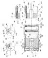
本発明に係る第1の参考例について、図1から図3を参照して説明する。
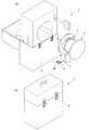
本参考例に係る内視鏡1は、細長な挿入部2を備えている内視鏡本体3と、この内視鏡本体3の挿入部2を巻回して収納するドラム部5とを主な構成要素としている。
内視鏡本体3は、ドラム部5を回動自在に収納するケース6内に格納、保管及び搬送される。A firstreference example according to the present invention will be described with reference to FIGS.
The
The endoscope body 3 is stored, stored, and transported in a
内視鏡本体3の挿入部2は観察対象の管腔内に挿入される柔軟で長尺な可撓管部7を備えている。
可撓管部7の先端には、照明光源等の電気機器が配されたアダプタ(撮像アダプタ)8や他のアダプタ8Aが着脱される後述する本体先端部10が配されている。The
At the distal end of the
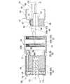
アダプタ8は所謂直視型のものであり、図2及び図3に示すように、対物レンズ11がアダプタ8の中心軸線C1方向に沿って配置されている。対物レンズ11は、略円筒状に形成されたレンズ筒部12の内部に収容され、複数のLEDチップ13が配されたLEDユニット(電気機器)15と共に円筒状に形成された外側部材16内に収容されている。 The
レンズ筒部12は、厚肉円筒状の基部12A、及び、基部12Aの先端面12aから突出して配され、外面が基部12Aの外径よりも小径とされ、かつ、内面は基部12Aの内径と略同一に形成された円筒壁12Bを備えている。基部12Aの基端面12bには略D字状断面の凹部17が形成されている。凹部17は、基部12Aの外周面上の二点を結ぶ線分の一部を含む第一平面18a及び外周面に沿う円弧の一部を含む第一曲面18bからなる側面部18と底部20とを備えている。 The
基部12Aの基端面12bの周端部には、径方向外方に突出したフランジ部12cが形成されている。このフランジ部12cには、レンズ筒部12に対して中心軸線C1回りに回転自在に係合された接続リング21が配されている。接続リング21の内面には、中心軸線C1に沿って配された第一雌ネジ部22A及び第二雌ネジ部22Bからなる雌ネジ部22が形成されている。 A
LEDユニット15は、軟質で円板状に形成されて複数のLEDチップ13が実装されたフレキ基板23と、アルミニウム等の金属からなりフレキ基板23をレンズ筒部12内で支持する厚肉円板状のアルミ基板25とを備えている。LEDユニット15は、レンズ筒部12の円筒壁12Bと嵌合して配されている。 The
アルミ基板25及びレンズ筒部12の基部12Aには、一端がフレキ基板23に電気的に接続された一対の電線(陽極側のみ図示)26が、中心軸線C1方向と略平行に延びて挿通するための挿通孔25a及び貫通孔12dがそれぞれ配されている。
一対の電線の他端には一対のアダプタ側端子基板27、28がそれぞれ接続されており、一対のアダプタ側端子基板27、28には一対のアダプタ側電極端子30、31がそれぞれ配されている。A pair of electric wires (only the anode side is shown) 26, one end of which is electrically connected to the flexible substrate 23, are inserted into the
A pair of adapter
一対のアダプタ側電極端子30、31は、一対のアダプタ側端子基板27、28を介してレンズ筒部12の凹部17の第一平面18aに、アダプタ8と挿入部2とを着脱する方向に対して直交する方向にそれぞれ対をなして配されている。この一対のアダプタ側電極端子30、31は、それぞれの端子のおもて面として径方向内方に向かうアダプタ側対向面(対向面)32をそれぞれ備えている。 The pair of adapter-
本体先端部10は、筒状に形成されて表面に接続リング21の雌ネジ部22と螺合される雄ネジ部33が形成された筒部35を備えている。筒部35の先端側には、断面略D字状に形成されてアダプタ8の凹部17と嵌合する凸部36が配されている。凸部36は、凹部17の第一平面18aと対向する第二平面37a及び凹部の第一曲面18bと対向する第二曲面37bからなる挿入部側側面部37と先端面38とを備えている。 The main body
本体先端部10の凸部36の第二平面37aには、ドラム部5内の図示しない電源(バッテリ等)から延びる電気配線40と接続された一対の挿入部側端子基板41、42が配されている。一対の挿入部側端子基板41、42には、アダプタ8と挿入部2とを装着する際に一対のアダプタ側電極端子30、31のそれぞれと接触してLEDユニット15と導通される一対の挿入部側電極端子43、45がそれぞれ配されている。なお、凸部36の中心軸線C2上には内視対象物を対物レンズ11を介して結像させるCCD46が配されている。 On the second
一対の挿入部側電極端子43、45は、アダプタ8を装着した際に一対のアダプタ側電極端子30、31と対向するように、それぞれの端子のおもて面として径方向内方に向かう挿入部側対向面(対向面)47を備えている。
中心軸線C2から挿入部側対向面47までの距離は、中心軸線C1からアダプタ側対向面32までの距離と略同一、若しくは、アダプタ側対向面32までの距離よりも、挿入部側対向面47までの距離が若干長いとされており、挿入部側対向面47とアダプタ側対向面32とが接触可能とされている。The pair of insertion portion
The distance from the central axis C2 to the insertion portion
凹部17の第一曲面18b及び凸部36の第二曲面37bには、中心軸線C1と中心軸線C2とを同一軸線としてアダプタ8を挿入部2に装着する際に、アダプタ側対向面32と挿入部側対向面47とを対向させるようにアダプタ8の向きを調整する位置決め部48が配されている。
位置決め部48は、凸部36の第二曲面37bに配された溝部48Aと、凹部17の第一曲面18bに径方向内方に突出して配されて溝部に係合される凸状の係合部48Bとを備えている。なお、一対のアダプタ側端子基板27、28と一対の挿入部側端子基板41、42とのように、それぞれの端子基板が対をなすように構成されているが、端子基板を分割しないで一体とし、その一体とした基板に端子を二つ配してもよい。The first
The positioning
次に、本参考例に係る内視鏡1を使用する際の作用・効果について説明する。
まず、所定のアダプタ8の凹部17の係合部48Bと本体先端部10の凸部36の溝部48Aとを係合させながら、凹部17内に凸部36を挿入する。
この際、一対のアダプタ側電極端子30、31のアダプタ側対向面32と一対の挿入部側電極端子43、45の挿入部側対向面47とが接触を開始し、挿入に伴って徐々に接触しながらその接触面積を増加させていく。Next, operations and effects when using the
First, the
At this time, the adapter
そして、雄ネジ部33とアダプタ8の接続リング21に係る雌ネジ部22とを螺合して、凸部36の先端面38とレンズ筒部12の凹部17の底部20とを接触させる。このとき、アダプタ側対向面32と挿入部側対向面47との接触面積が最大となる。即ち、一対のアダプタ側電極端子30、31に、一対の挿入部側電極端子43、45が押し付けられて、互いに密着した状態となる。従って、一対のアダプタ側電極端子30、31及び一対の挿入部側電極端子43、45がそれぞれ導通してアダプタ8と本体先端部10とが電気的に接続される。
こうして、観察対象となる図示しない管腔内に挿入部2を挿入して所定の観察を行う。Then, the
Thus, a predetermined observation is performed by inserting the
観察を終了した後は、管腔内から挿入部2を抜去して、接続リング21と本体先端部10との螺合を解除する。このとき、一対のアダプタ側電極端子30、31のアダプタ側対向面32と一対の挿入部側電極端子43、45の挿入部側対向面47とが離間し始め、アダプタ8と挿入部2との電気的な接続も解除される。 After ending the observation, the
この内視鏡1によれば、一対のアダプタ側電極端子30、31と一対の挿入部側電極端子43、45とをそれぞれの対向面32、47にて面接触させることができ、しかも接触面積を装着開始時から装着完了時にかけて漸次増大させることができる。従って線接触の場合よりもアダプタ8と挿入部2とを電気的に確実に接続させることができる。 According to this
ここで、一対のアダプタ側電極端子30、31及び一対の挿入部側電極端子43、45が、アダプタ8の着脱方向とは異なる法線を有する第一平面18a及び第二平面37aに、それぞれ着脱方向に対して垂直方向に並んで配されている。その結果、アダプタ8を着脱する際に、一対のアダプタ側電極端子30、31と一対の挿入部側電極端子43、45とを同時に接触させることができ、端子の接触回数を好適な回数として端子の摩耗を最小限に抑えることができる。
従って、一対のアダプタ側電極端子30、31と一対の挿入部側電極端子43、45とを小型でも確実な接触力にて接触させることができ、挿入部2及びアダプタ8の小型化を図ることができる。Here, the pair of adapter-
Accordingly, the pair of adapter-
また、位置決め部48を備えているので、位置決め部48にて位置合わせさせながらアダプタ8を挿入部2に装着することによって、一対のアダプタ側電極端子30、31及び一対の挿入部側電極端子43、45の各対向面32、47を容易に、かつ、確実に接触させることができる。 In addition, since the
次に、第2の参考例について図4を参照しながら説明する。
なお、上述した第1の参考例と同様の構成要素には同一符号を付すとともに説明を省略する。
第2の参考例と第1の参考例との異なる点は、本参考例に係る内視鏡50が有する一対のアダプタ側電極端子のアダプタ側電極端子30(陽極側のみ図示)のアダプタ側対向面32と、一対の挿入部側電極端子の挿入部側電極端子43(陽極側のみ図示)の挿入部側対向面47とが、アダプタ51と挿入部52とを着脱する方向となるアダプタ51の中心軸線Cに対して一定の角度αで傾斜する方向に対向するように配されているとした点である。Next, a secondreference example will be described with reference to FIG.
In addition, the same code | symbol is attached | subjected to the component similar to the 1streference example mentioned above, and description is abbreviate | omitted.
The difference between the secondreference example and the firstreference example is that the adapter side electrode terminal 30 (only the anode side is shown) of the pair of adapter side electrode terminals of the
アダプタ51のレンズ筒部53は、基部53Aの基端面53bに形成される凹部55の側面部56の第一平面56aが、凹部55の底部20から基部53Aの基端面53bに向かって略D字状断面が漸次拡大するように中心軸線C1に対して傾斜して形成されている。この第一平面56aに、アダプタ側電極端子30が図示しない陰極側の端子とともに中心軸線C1と直交する方向に並んで配されている。 In the lens tube portion 53 of the
一方、アダプタ側対向面32と挿入部側対向面47との対向状態が維持されるように、本体先端部57における凸部58の挿入部側側面部60の第二平面60aが、凸部58の先端面61に向かって略D字状断面が漸次縮小するように、中心軸線C1と平行とされる中心軸線C2に対して傾斜して形成されている。 On the other hand, the second
次に、本参考例に係る内視鏡50を使用する際の作用・効果について説明する。
まず、第1の参考例と同様に、アダプタ51の凹部55の係合部48Bと本体先端部57の凸部58の溝部48Aとを係合させながら、凹部55内に凸部58を挿入する。
この際、挿入開始直後では、第一平面56aと第二平面60aとが中心軸線Cに対して同一の角度で傾斜しているので、アダプタ側電極端子30のアダプタ側対向面32と挿入部側電極端子43の挿入部側対向面47とはまだ接触し始めない。Next, actions and effects when using the
First, as in the firstreference example , the
At this time, immediately after the start of insertion, the
そして、雄ネジ部33にアダプタ51の接続リング21に係る雌ネジ部22と螺合して、凸部58の先端面61と凹部55の底部20とを接触させる。このとき、中心軸線Cからアダプタ側対向面32及び挿入部側対向面47までの距離が略同一、若しくは、アダプタ側対向面32までの距離よりも、挿入部側対向面47までの距離が若干長いとされているので、アダプタ側対向面32と挿入部側対向面47とが接触を開始し、螺合を終了するまでの間に接触面積が漸次増加する。 Then, the
こうして、螺合完了時には面積が最大となって、アダプタ側電極端子30及び挿入部側電極端子43がそれぞれ導通してアダプタ51と本体先端部57とが電気的に接続される。
その後は、第1の参考例と同様に観察対象となる図示しない管腔内に挿入部52を挿入して所定の観察を行う。Thus, when the screwing is completed, the area becomes maximum, the adapter
Thereafter, as in the firstreference example , the
観察を終了した後は、管腔内から挿入部52を抜去して、接続リング21と本体先端部57との螺合を解除する。このとき、アダプタ側電極端子30のアダプタ側対向面32と挿入部側電極端子43の挿入部側対向面47とが離間し、アダプタ51と挿入部52との電気的な接続も解除される。 After the observation is finished, the
この内視鏡50によれば、アダプタ51を挿入部52に装着する最初からアダプタ側電極端子30と挿入部側電極端子43との対向面32、47を接触させなくても、アダプタ51の装着完了時にはお互いを面接触させることができる。従って、アダプタ51の着脱を繰り返しても電極端子30、43の摩耗をより好適に抑えることができる。 According to this
次に、第1の実施形態について図5を参照しながら説明する。
なお、上述した各参考例と同様の構成要素には同一符号を付すとともに説明を省略する。
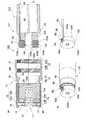
第1の実施形態と第1の参考例との異なる点は、本実施形態に係る内視鏡70のアダプタ71におけるフレキ基板72が、帯状に形成されてレンズ筒部73の側面を先端面73a側から基端面73bまで延びる延部72Aを備えており、一対のアダプタ側電極端子30、31が一対のアダプタ側端子基板27、28上ではなく延部72Aに形成された図示しない配線パターン上に配されているとした点である。Next, afirst embodiment will be described with reference to FIG.
In addition, the same code | symbol is attached | subjected to the component similar toeach reference example mentioned above, and description is abbreviate | omitted.
First embodiment and is different from the firstreference example,
レンズ筒部73の基部73Aに形成された凹部75は、底部76が基部73Aよりも小径の略円形とされ、側面部77と基部73Aの外周面との間が、薄い肉厚の円環状の壁部78とされている。
基部73Aに配された貫通孔73dは、側面部77近傍の底部76とレンズ筒部73の先端面73aとを挿通するように中心軸線C1方向に沿って形成されている。
貫通孔73dは延部72Aが挿通可能な大きさに形成されている。
凹部75の側面部77には、図示しない位置決め部の係合部が配されている。The
The through
The through
An engaging portion of a positioning portion (not shown) is disposed on the
フレキ基板72は、LEDチップ13が配される円板部72Bをさらに備えており、延部72Aが円板部72Bの一部から突出して形成され、可撓性を有してアルミ基板80の側面に沿うように折り曲げられている。延部72Aの端部には、一対のアダプタ側電極端子30、31が中心軸線C1に対して直交する方向に並んで配されており、図示しないパターンを介して円板部72Bに配されたLEDチップ13と電気的に接続されている。
延部72Aは断面略矩形状とされている。そのため、延部72Aを貫通孔73dに挿通した際、レンズ筒部73の凹部75の側面部77は曲面であるのに対して延部72Aの側面が平面なので、延部72Aと貫通孔73dとの間に隙間78Aが形成される。The
The extending
アルミ基板80には第1の参考例における挿通孔25aのようなものは形成されておらず、その代わりに外径がレンズ筒部73の基部73Aと略同一に形成されている。アルミ基板80の側面には、フレキ基板72の延部72Aが係合してアルミ基板80に埋設可能な形状の溝80Aが形成されている。The
挿入部81に配される電気配線40には帯状の挿入部側フレキ基板82が接続されており、一対の挿入部側電極端子83、85が、挿入部側フレキ基板82の先端部に中心軸線C2方向に対して直交する方向に並んで配されている。 A strip-shaped insertion portion side
挿入部81の本体先端部86に配された筒部87は、凹部75と嵌合可能な外径とされており、筒部87の先端面87aが凹部75の底部76と当接可能とされている。この筒部87の側面には、フレキ基板72の延部72Aと係合してこれを筒部87内に埋設可能な大きさの切り欠き部88が形成されている。
切り欠き部88は、筒部87内に延設された挿入部側フレキ基板82の端部82aが載置可能、かつ、中心軸線Cからアダプタ側対向面32及び挿入部側対向面47のそれぞれとの距離が略同一、若しくは、アダプタ側対向面32までの距離よりも、挿入部側対向面47までの距離が若干長いとなる深さに形成されている。The
The
次に、本実施形態に係る内視鏡70を使用する際の作用・効果について説明する。
まず、アダプタ71と本体先端部86とを図示しない位置決め部によって係合させながら、接続リング21内に本体先端部86の筒部87を挿入する。このとき、第1の参考例と同様に、中心軸線Cからアダプタ側対向面32及び挿入部側対向面47までの距離が略同一、若しくは、アダプタ側対向面32までの距離よりも、挿入部側対向面47までの距離が若干長いとされているので、アダプタ側対向面32と挿入部側対向面47とが接触を開始する。そして、雄ネジ部33と雌ネジ部22とを螺合して筒部87の先端面87aとレンズ筒部73の凹部75の底部76とを当接させる。Next, operations and effects when using the
First, the
そして、レンズ筒部73の側面に沿って配されたフレキ基板72の延部72Aに一対のアダプタ側電極端子30、31が配されているので、アダプタ71の装着時に一対の挿入部側電極端子83、85と一対のアダプタ側電極端子30、31とが接触した際、延部72Aが隙間78A内を径方向外方に弾性変形する。 And since the pair of adapter
こうして、対向面32、47の接触圧力が延部72Aの弾性変形によって調整されながらアダプタ側対向面32と挿入部側対向面47とが完全に接触される。
その後は、上記第1の参考例と同様の作業を行う。
この内視鏡70によれば、第1の参考例と同様の作用・効果を奏することができる。
特に、対向面32、47間に生じる摩擦力を調整することができ、より好適な接触状態とすることができる。Thus, the adapter
Thereafter, the same operation as in the firstreference example is performed.
According to the
In particular, the frictional force generated between the opposing
次に、第2の実施形態について図6を参照しながら説明する。
なお、上述した他の参考例および実施形態と同様の構成要素には同一符号を付すとともに説明を省略する。
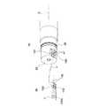
第2の実施形態と第1の実施形態との異なる点は、上記第1の実施形態に係る内視鏡70のアダプタ71では、レンズ筒部73の基部73Aに凹部75が配されているのに対し、本実施形態に係る内視鏡90のアダプタ91におけるレンズ筒部92の基部92Aには、フレキ基板72の延部72Aの板幅と略同一の板幅を有してレンズ筒部92の基端面92bから突出して形成され、レンズ筒部92の径方向に湾曲可能な支持部93が配されているとした点である。Next, asecond embodiment will be described with reference to FIG.
In addition, the same code | symbol is attached | subjected to the component similar to the otherreference example and embodiment mentioned above, and description is abbreviate | omitted.
The difference between thesecond embodiment and thefirst embodiment is that in the
支持部93は、接続リング21の内壁面との間に隙間を形成するような板厚とされ、かつ、本体先端部86の筒部87に配された切り欠き部88に埋設可能な形状とされている。
レンズ筒部92の貫通孔92dは、基部92Aの先端面92aからではなく、側面の一部から基部92Aの内部を中心軸線C1方向に基端面92bに向かって形成されている。フレキ基板72の延部72Aは、貫通孔92dに挿通された際に、基端面92bから突出して支持部93の内面に支持されている。
図示しない位置決め部の係合部は、外側部材16の内面に配されており、図示しない溝部は本体先端部86の筒部87に配されている。The
The through
The engaging portion of the positioning portion (not shown) is arranged on the inner surface of the
この内視鏡90を使用する際の作用・効果について説明する。
第1の実施形態と同様に、アダプタ側対向面32と挿入部側対向面47との接触を開始する。そして、雄ネジ部33と雌ネジ部22とを螺合して筒部87の先端面87aとレンズ筒部92の基部92Aの基端面92bとを当接させる。
この際、アダプタ91の装着時に一対の挿入部側電極端子83、85と一対のアダプタ側電極端子30、31とが接触した際、支持部93が隙間内を径方向外方に湾曲する。Actions and effects when using the
Similarly to thefirst embodiment, contact between the adapter
At this time, when the pair of insertion portion
こうして、対向面32、47間の接触圧力が支持部93の湾曲によって調整されながらアダプタ側対向面32と挿入部側対向面47とが完全に接触される。
その後は、上記第1の参考例と同様の作業を行う。Thus, the adapter
Thereafter, the same operation as in the firstreference example is performed.
この内視鏡90によれば、第1の実施形態に係る内視鏡70と比べた際、支持部93が壁部78よりも中心軸線Cに対する幅方向の長さが短く湾曲しやすいので、フレキ基板72の延部72Aをより好適に変形させることができ、アダプタ側対向面32と挿入部側対向面47との接触時における摩擦力をより容易に調整することができる。According to this
次に、第3の参考例について図7を参照しながら説明する。
なお、上述した他の参考例および実施形態と同様の構成要素には同一符号を付すとともに説明を省略する。
第3の参考例と上記第1又は第2の実施形態との異なる点は、本参考例に係る内視鏡100のアダプタ101には、フレキ基板102と電気的に接続される筒状フレキ基板103が配されているとした点である。Next, athirdreference example will be described with reference to FIG.
In addition, the same code | symbol is attached | subjected to the component similar to the otherreference example and embodiment mentioned above, and description is abbreviate | omitted.
The difference between thethirdreference example and thefirst orsecond embodiment is that the
レンズ筒部105の基部105Aの基端面105bは平坦面とされている。
フレキ基板102の延部102Aの長さは、アルミ基板80の中心軸線C1方向の厚さと略同一とされており、外表面にLEDチップ13のための一対の接続端子106、107が形成されている。The
The length of the
筒状フレキ基板103は、シート状の基板が、延部102a及びレンズ筒部105の外周面を覆うように円筒状に巻回されて形成されている。筒状フレキ基板103の中心軸線C1方向の長さは、この方向にアルミ基板80とレンズ筒部105とを連接したときの長さよりも長くなるように形成されている。筒状フレキ基板103の内面には、一端側が一対の接続端子106、107と接触して中心軸線C1方向に延びるパターン108が配されている。
一対のアダプタ側電極端子30、31は、パターン108の他端側に配されている。
外側導体110の基端には、接続リング21が係合するフランジ部110aが配されている。The cylindrical
The pair of adapter
At the base end of the
本体先端部111は、第1の参考例に係る内視鏡1の場合と同様に、電気配線40が筒部112の先端近傍まで延びて配されている。筒部112の側面には、挿入部側電極端子43が配された挿入部側端子基板41と、図示しない陰極側の挿入部側電極端子が配された図示しない陰極側の挿入部側端子基板とを筒部112の側面の周方向に沿って載置可能な切り欠き部113が配されている。As in the case of the
この内視鏡100を使用する際の作用・効果について説明する。
第1の参考例と同様に、アダプタ側対向面32と挿入部側対向面47との接触を開始する。そして、雄ネジ部33と雌ネジ部22とを螺合して筒部112の先端面112aとレンズ筒部105の基部105Aの基端面105bとを当接させる。
この際、挿入部側電極端子43とアダプタ側電極端子30とが中心軸線C方向に接触し始め、アダプタ側対向面32と挿入部側対向面47とが完全に接触される。
こうして、アダプタ101が本体先端部111と電気的に接続される。Actions and effects when using the
Similar to the firstreference example, contact between the adapter
At this time, the insertion portion
Thus, the
この内視鏡100によれば、本参考例に係る筒状フレキ基板103が、第1の実施形態に係るレンズ筒部105の壁部78と同様の作用を奏することから、上記第1の実施形態に係る内視鏡70と同様の作用・効果を奏することができる。According to the
次に、第3の実施形態について図8を参照しながら説明する。
なお、上述した他の参考例および実施形態と同様の構成要素には同一符号を付すとともに説明を省略する。
第3の実施形態と第1の実施形態との異なる点は、本実施形態に係る内視鏡120の本体先端部121に、アダプタ71を挿入部122に装着する際、一対のアダプタ側電極端子のアダプタ側電極端子(陽極側のみ図示)30と一対の挿入部側電極端子83、85の挿入部側電極端子83との押圧力を漸次増大させるゴム部材(付勢手段)123が、筒部125の先端面125aから突出して形成された円筒壁126と嵌合して配されているとした点である。Next, athird embodiment will be described with reference to FIG.
In addition, the same code | symbol is attached | subjected to the component similar to the otherreference example and embodiment mentioned above, and description is abbreviate | omitted.
The difference between thethird embodiment and thefirst embodiment is that when the
ゴム部材123は、平坦面からなる第一側面123a及び筒部125と略同一径の円弧面からなる第二側面123bを有して断面D字状に形成されており、中心部には筒部125の円筒壁126と嵌合される孔123cが配されている。
ゴム部材123の先端面123dは、ゴム部材123が円筒壁126に嵌合された際、本体先端部121の筒部125先端よりも僅かに突出するように配されている。The
The
ゴム部材123の第一側面123aには、挿入部側フレキ基板82の端部82aが載置されている。この際、中心軸線Cから挿入部側対向面47までの距離は、中心軸線Cからアダプタ側対向面32までの距離と略同一とされている。 On the
次に、本実施形態に係る内視鏡120を使用する際の作用・効果について説明する。
まず、ゴム部材123の先端面123dとレンズ筒部73の凹部75の底部76とが当接するまで、アダプタ71の接続リング21及び外側部材16に本体先端部121の筒部125を挿入する。
このとき、挿入部側対向面47とアダプタ側対向面32とが対向した状態となるが、まだ両者は接触していない。
そして、本体先端部121の雄ネジ部33と接続リング21の雌ネジ部22とを螺合する。Next, operations and effects when using the
First, the
At this time, the insertion portion
Then, the
このとき、ゴム部材123に中心軸線C方向の圧縮力が負荷され、筒部125からの抵抗力によって径方向外方に弾性変形してゴム部材123の外径が増大する。その結果、中心軸線Cから挿入部側対向面47までの距離が変化して挿入部側対向面47が径方向外方に移動する。そして、アダプタ側対向面32と接触を開始する。
こうして螺合を終了するまでの間に接触面積が漸次増加して、螺合完了時には接触面積が最大となって、アダプタ71と挿入部122とが電気的に接続される。At this time, a compressive force in the direction of the central axis C is applied to the
Thus, the contact area gradually increases until the screwing is completed, and when the screwing is completed, the contact area becomes maximum, and the
この内視鏡120によれば、ゴム部材123を押圧することによって径方向外方に変形させてアダプタ側電極端子30と挿入部側電極端子83との接触面積を増大させることができ、対応する各対向面32、47をより確実に接触させることができる。この際、ゴム部材123を圧縮しない限り挿入部側対向面47とアダプタ側対向面32とが接触しないので、一対のアダプタ側電極端子と一対の挿入部側電極端子との摩耗を好適に抑えることができる。 According to the
次に、第4の実施形態について図9を参照しながら説明する。
なお、上述した他の参考例および実施形態と同様の構成要素には同一符号を付すとともに説明を省略する。
第4の実施形態と第1の実施形態との異なる点は、本実施形態に係る内視鏡130のアダプタ131に係るレンズ筒部132に、径方向に湾曲して押圧力を付与する板バネ部(付勢手段、バネ部材)133が配されているとした点である。Next, afourth embodiment will be described with reference to FIG.
In addition, the same code | symbol is attached | subjected to the component similar to the otherreference example and embodiment mentioned above, and description is abbreviate | omitted.
The difference between thefourth embodiment and thefirst embodiment is that a leaf spring that is curved in the radial direction and applies a pressing force to the
板バネ部133は、中心軸線C1方向に沿った側面132eにおけるレンズ筒部132の基部132Aの先端面132aから基端面132bに向かう一部が切り離されて形成されている。一方、板バネ部133が切り離された後のレンズ筒部132の側面132eには、孔部132fが形成されている。板バネ部133は、孔部132f内で径方向に湾曲可能とされている。
板バネ部133の端部133aは、凹部75内に向かって突出するように形成されている。The
The
フレキ基板135の延部135aは、板バネ部133の外周面に沿って配され、端部135aが板バネ部133の端部133aで折り返されて固定されている。
アダプタ側電極端子30(陽極側のみ図示)は、凹部75内に折り返された延部135Aの表面に配されている。The extending
The adapter-side electrode terminal 30 (only the anode side is shown) is disposed on the surface of the extending
フレキ基板135の円板部135Bは、アルミ基板ではなくレンズ筒部132の基部132Aの先端面132aに配されている。
外側部材136の内面には、板バネ部133が湾曲変形した際に、外側部材136によって規制される範囲を少なくして湾曲移動範囲を確保するための凹状部136Aが形成されている。The
A
本体先端部86の挿入部側フレキ基板82と切り欠き部88との間には、シート状の弾性体137が配されている。この弾性体137の厚さは、アダプタ131が本体先端部86に装着可能な程度に、中心軸線Cからアダプタ側対向面32までの距離が中心軸線Cから挿入部側対向面47までの距離よりも小さくなるように調整されている。 A sheet-like
次に、本実施形態に係る内視鏡130を使用する際の作用・効果について説明する。
まず、図示しない位置決め部に沿ってアダプタ131の凹部75に本体先端部86の筒部87を挿入する。
この際、アダプタ側電極端子30のアダプタ側対向面32と挿入部側電極端子83の挿入部側対向面47とが接触を開始する。このとき、アダプタ側電極端子30には、径方向外方に向かう力が挿入部側電極端子83から負荷されるため、アダプタ側対向面32と挿入部側対向面47とが接触した状態で板バネ部133が孔部132f内を径方向外方に湾曲する。Next, operations and effects when using the
First, the
At this time, the adapter
一方、挿入部側電極端子83は、径方向内方に向かう力がアダプタ側電極端子30から負荷されるため、挿入部側フレキ基板82が、弾性体137を圧縮させながら径方向内方に湾曲する。 On the other hand, since the insertion portion
雄ネジ部33とアダプタ131の接続リング21に係る雌ネジ部22とを螺合して、筒部87の先端面87aとレンズ筒部132の凹部75の底部76とを接触させる。このとき、湾曲した板バネ部133の端部133aが外側部材136の凹状部136Aに当接する。そして、外側部材136から径方向内方に向かう力が負荷される。
従って、一定の付勢力が維持されてアダプタ側対向面32と挿入部側対向面47との接触面積が一定に維持され、一対のアダプタ側電極端子及び一対の挿入部側電極端子がそれぞれ導通して、アダプタ131と本体先端部86とが電気的に接続される。The
Accordingly, a constant urging force is maintained, the contact area between the adapter
この内視鏡130によれば、アダプタ装着の際、一対のアダプタ側電極端子及び一対の挿入部側電極端子との接触面積を、板バネ部133を変形させることによって付勢力を調整しながら漸次増加させることができ、一対のアダプタ側電極端子及び一対の挿入部側電極端子の摩耗を好適に抑えることができる。 According to the
次に、第5の実施形態について図10を参照しながら説明する。
なお、上述した他の実施形態と同様の構成要素には同一符号を付すとともに説明を省略する。
第5の実施形態と第4の実施形態との異なる点は、本実施形態に係る内視鏡140のアダプタ141に係る一対のアダプタ側電極端子のアダプタ側電極端子142(陽極側のみ図示)が、板バネ状の弾性部材として形成され、アダプタ側対向面143が、中心軸線Cに対して一定の角度αで傾斜して配されているとした点である。Next, afifth embodiment will be described with reference to FIG.
In addition, the same code | symbol is attached | subjected to the component similar to other embodiment mentioned above, and description is abbreviate | omitted.
The difference between thefifth embodiment and thefourth embodiment is that an adapter side electrode terminal 142 (only the anode side is shown) of the pair of adapter side electrode terminals related to the
アダプタ側電極端子142は、フレキ基板135の延部135Aに接続された状態に対して、フレキ基板135の延部135Aに対して一定の角度αで径方向内方に向かって折り返されて形成されている。折り返し部分には空間部142Aが形成されている。 The adapter-
レンズ筒部145の基部145Aの側面145eの一部には、基部145Aの先端面145aから中心軸線C1方向に沿って所定の長さで基端面145bに向かう係合溝146が配されている。この係合溝146は、フレキ基板135の延部135Aが嵌合されて埋設可能な断面形状とされている。そして、係合溝146の端部146aには、延部135Aの端部に配されたアダプタ側電極端子142がレンズ筒部145の外表面から凹部75の側面部77に貫通可能な孔部145fが形成されている。
アダプタ側電極端子142のアダプタ側対向面143と挿入部側電極端子83の挿入部側対向面47とはアダプタ141を装着するまでは対向しない状態となっている。An
The adapter
次に、本実施形態に係る内視鏡140を使用する際の作用・効果について説明する。
まず、図示しない位置決め部に沿ってアダプタ141の凹部75に本体先端部86の筒部87を挿入する。
この際、アダプタ側対向面143と挿入部側対向面47とが接触を開始する。このとき、アダプタ側電極端子142には径方向外方に向かう力が負荷され、最初にフレキ基板135の延部135Aが径方向外方に湾曲変形する。Next, operations and effects when using the
First, the
At this time, the adapter
さらに装着を進めるにつれて、フレキ基板135の延部135Aが外側部材136の凹状部136Aと当接して変形が停止する。この後は、アダプタ側電極端子142が空間部142Aを小さくする方向に弾性変形する。そしてアダプタ側対向面143と挿入部側電極端子83の挿入部側対向面47との接触面積が漸次増大して、アダプタ側電極端子142と挿入部側電極端子83とが略平行状態となる。 As the mounting is further advanced, the
雄ネジ部33とアダプタ141の接続リング21に係る雌ネジ部22とを螺合して、筒部87の先端面87aとレンズ筒部145の凹部75の底部76とを接触させる。このとき、アダプタ側対向面143と挿入部側対向面47との接触面積が一定に維持された状態で互いに対向して接触する状態となって、一対のアダプタ側電極端子及び一対の挿入部側電極端子がそれぞれ導通してアダプタ141と本体先端部86とが電気的に接続される。 The
この内視鏡140によれば、アダプタ141と本体先端部86とを装着して板バネ状の一対のアダプタ側電極端子を変形させることによって、一対のアダプタ側電極端子及び一対の挿入部側電極端子の接触面積を徐々に増大させながら接触させることができ、かつ、両者の摩耗を好適に抑えることができる。 According to this
なお、図11(a)に示すように、一対の挿入部側電極端子150、151が中心軸線Cに対して一定の角度αに傾斜した板バネ状に形成されていても構わない。このとき、図11(b)に示すように、アダプタ側電極端子152、153が、アダプタ側対向面143が中心軸線Cに対して一定の角度αに傾斜して挿入部側対向面47と対向する弾性変形しない金属体として形成されていても構わない。 As shown in FIG. 11A, the pair of insertion portion
次に、第4の参考例について図12を参照しながら説明する。
なお、上述した他の参考例および実施形態と同様の構成要素には同一符号を付すとともに説明を省略する。
第4の参考例と第5の実施形態との異なる点は、本参考例に係る内視鏡160のアダプタ161において、フレキ基板162の延部162Aと円板部162Bとが分離され、両者が一対の電線163、165によって接続されているとした点である。Next, afourthreference example will be described with reference to FIG.
In addition, the same code | symbol is attached | subjected to the component similar to the otherreference example and embodiment mentioned above, and description is abbreviate | omitted.
The difference between thefourthreference example and thefifth embodiment is that, in the
延部162Aの基端には、中心軸線C1方向に対して一定の角度αで径方向内方に向かって折り返された板バネ部166が接続されている。板バネ部166の折り返し部分には空間部166Aが形成されている。フレキ基板162の延部162Aの端部側は、板バネ部166に沿って折り返されている。
一対のアダプタ側電極端子30、31は、延部162Aの端部162aの折り返されて径方向内方に向かう面に配されている。A
The pair of adapter-
この内視鏡160によれば、一対のアダプタ側電極端子30、31がフレキ基板162に接続された板バネ部166の表面に配され、延部162Aと円板部162Bとが一対の電線163、165で接続されているので、第5の実施形態と同様の作用・効果を奏することができる。
なお、フレキ基板162と板バネ部166とを一対の電線163、165で接続する代わりに、図13に示すように、フレキ基板162の円板部162Bはそのままとして延部162Aの基端側を径方向内方に向かって折り返して、板バネ状の延部167Aするフレキ基板167としても構わない。According to the
Instead of connecting the
次に、第6の実施形態について図14を参照しながら説明する。
なお、上述した他の実施形態と同様の構成要素には同一符号を付すとともに説明を省略する。
第6の実施形態と第1の実施形態との異なる点は、本実施形態に係る内視鏡170の本体先端部171の挿入部側フレキ基板172が、筒部173の先端に配されているとした点である。Next, asixth embodiment will be described with reference to FIG.
In addition, the same code | symbol is attached | subjected to the component similar to other embodiment mentioned above, and description is abbreviate | omitted.
The difference between thesixth embodiment and thefirst embodiment is that the insertion portion side
挿入部側フレキ基板172は、円板状に形成され筒部173を貫通して延びる電気配線40が貫通可能とされた円板部172Aと、円板部172Aの周縁部の一部から中心軸線C2に対して一定の角度で傾斜して延びる端子部172Bとを備えている。円板部172Aと端子部172Bとは一体に形成されており、端子部172Bは円板部172Aに対して板バネ状に湾曲可能とされている。端子部172Bの表面には一対の挿入部側電極端子83、85が配されている。 The insertion portion side
本体先端部171の筒部173の先端面173aには、挿入部側フレキ基板172を収納可能な挿入部側凹部175が形成されている。挿入部側凹部175は、アダプタ71の凹部75と同様に底部176と側面部177とを備えており、側面部177の一部には、底部176と切り欠き部178とを直接つなげるための第二切り欠き部179が形成されている。なお、図示しない位置決め部の溝部が挿入部側凹部175の側面部177に形成されている。 An insertion
次に、本実施形態に係る内視鏡170を使用する際の作用・効果について説明する。
まず、図示しない位置決め部に沿ってアダプタ71の凹部75に本体先端部171の筒部173を挿入する。
この際、挿入部側対向面47とアダプタ側電極端子30(陽極側のみ図示)のアダプタ側対向面32とが接触を開始する。このとき、挿入部側電極端子83には、径方向内方に向かう力が負荷されるため、一対の挿入部側電極端子83、85が径方向内方に押圧される。従って、挿入部側フレキ基板172の端子部172Bが中心軸線Cに沿う方向に湾曲し、挿入部側対向面47とアダプタ側対向面32との接触面積が増大しながら互いに略平行状態となる。Next, operations and effects when using the
First, the
At this time, the insertion portion
雄ネジ部33とアダプタ71の接続リング21に係る雌ネジ部22とを螺合して、筒部173の先端面173aとレンズ筒部73の凹部75の底部76とを接触させる。このとき、アダプタ側対向面32と挿入部側対向面47との接触面積が一定に維持された状態で互いに対向して接触する状態となって、一対のアダプタ側電極端子及び一対の挿入部側電極端子がそれぞれ導通してアダプタ71と本体先端部171とが電気的に接続される。 The
この内視鏡170によれば、一対の挿入部側電極端子83、85が、円板部172Aに対して板バネ状に変形する挿入部側フレキ基板172の端子部172Bに配されているので、アダプタ71を本体先端部171に装着して端子部172Bを変形させることによって、徐々に一対のアダプタ側電極端子及び一対の挿入部側電極端子の接触面積を増大させながら接触させることができ、かつ、両者の摩耗を好適に抑えることができる。 According to the
次に、第7の実施形態について図15を参照しながら説明する。
なお、上述した他の実施形態と同様の構成要素には同一符号を付すとともに説明を省略する。
第11の実施形態と第3の実施形態との異なる点は、本実施形態に係る内視鏡180の本体先端部181の挿入部側フレキ基板182が、図15(a)に示すように、筒部183の先端で折り返されて配されているとした点である。Next, aseventh embodiment will be described with reference to FIG.
In addition, the same code | symbol is attached | subjected to the component similar to other embodiment mentioned above, and description is abbreviate | omitted.
The difference between the eleventh embodiment and the third embodiment is that the insertion portion side
挿入部側フレキ基板182は、図15(b)(c)に示すように、電気配線40と接続されるパターン185が先端側まで延びて形成されて筒部183と接触して配される第一側面182aと、第一側面182aの反対側の側面とされて筒部183の径方向外方に向かって配される第二側面182bとを備えて矩形平板状に形成されている。 As shown in FIGS. 15B and 15C, the insertion portion side
挿入部側フレキ基板182の先端側は、図15(d)に示すように、中心軸線C2に対して一定の角度αで傾斜する方向に向かって第一側面182a側に折り返され、空間部182Aを形成して第一側面182a同士が接触するまで弾性変形可能とされている。
一対の挿入部側電極端子83、85は、図15(e)に示すように、パターン185の先端から所定の距離に離間して第二側面182bに配されている。一対の挿入部側電極端子83、85が配された位置の第一側面182aには、各電極端子83、85に対応する第一接点187が配されている。
パターン185の先端には、挿入部側フレキ基板182の先端側を折り返した際に、第一接点187と対向する第二接点188が配されている。As shown in FIG. 15 (d), the distal end side of the insertion portion side
As shown in FIG. 15E, the pair of insertion portion
A
挿入部側フレキ基板182の先端を折り返した際に形成される空間部182Aには、図14(e)に示すように、押圧された際に押圧方向に導電性を有するシート状の導電ゴム(付勢手段、ゴム部材)189が配されている。 In the
ここで導電ゴム189は、シリコンゴム等の絶縁性のゴム素材に、ニッケル粒子や金メッキを施した金属粒子等の導電部材をドット状に埋設して構成されたものとされ、通常、ドットタイプの異方導電性ゴム等と呼ばれている。この導電ゴム189は、弾性体であるゴム素材を厚さ方向に押圧した際、その圧縮変形によって高密度化した導電部材間の導電性が増し、それによって厚み方向の通電が許容されるようになる。この際、ゴム素材が絶縁部材であることから、ゴム素材の厚み方向以外の方向(例えば、周方向)については絶縁状態が維持される。 Here, the
次に、本実施形態に係る内視鏡180を使用する際の作用・効果について説明する。
まず、図示しない位置決め部に沿って、図15(f)に示すアダプタ71の凹部75に本体先端部181の筒部183を挿入する。
この際、一対の挿入部側電極端子83、85の挿入部側対向面47と一対のアダプタ側電極端子30、31のアダプタ側対向面32とが接触を開始する。Next, operations and effects when using the
First, the
At this time, the insertion portion
このとき、挿入部側フレキ基板182の折返された先端部分には径方向内方に向かう力が負荷されるため、空間部182Aが小さくなるように先端部分が中心軸線C2と略平行状態となる方向に変形する。そして、第一接点187と第二接点188とによって導電ゴム189が挟まれて圧縮変形される。 At this time, since a force directed radially inward is applied to the folded tip portion of the insertion portion side
これによって、導電ゴム189とパターン185及び導電ゴム189と一対の挿入部側電極端子83、85との密着度が高まり、導電ゴム189の径方向の導電性が高まって一対の挿入部側電極端子83、85とパターン185とが電気的に接続される。
これと同時に挿入部側対向面47とアダプタ側対向面32との間の接触面積が漸次増大する。As a result, the degree of adhesion between the
At the same time, the contact area between the insertion portion
雄ネジ部33とアダプタ71の接続リング21に係る雌ネジ部22とを螺合して、筒部183の先端面183aとレンズ筒部73の凹部75の底部76とを接触させる。このとき、アダプタ側対向面32と挿入部側対向面47との接触面積が一定に維持された状態で互いに対向して接触する状態となって、一対のアダプタ側電極端子30、31及び一対の挿入部側電極端子83、85がそれぞれ導通してアダプタ71と本体先端部181とが電気的に接続される。 The
この内視鏡180によれば、一対の挿入部側電極端子83、85が、導電ゴム189を介して同じ挿入部側フレキ基板182のパターン185と電気的に接触する際、アダプタ装着に合わせて導電ゴム189を押圧変形させることによって、徐々に一対の挿入部側電極端子83、85とパターン185との電気的な接触状態を向上させることができる。 According to this
一方、アダプタ71を本体先端部181に装着することによって導電ゴム189が弾性変形するため、第7の実施形態と同様に、徐々に一対のアダプタ側電極端子30、31及び一対の挿入部側電極端子83、85の接触面積を増大させながら接触させることができ、かつ、両者の摩耗を好適に抑えることができる。 On the other hand, since the
次に、第8の実施形態について図16を参照しながら説明する。
なお、上述した他の参考例および実施形態と同様の構成要素には同一符号を付すとともに説明を省略する。
第8の実施形態と第7の実施形態との異なる点は、図16(a)、(b)に示すような本実施形態に係る内視鏡190のアダプタ191の一対のアダプタ側電極端子192、193が、図16(c)、(d)に示すように、径方向内方に向かって漸次コイル径が縮径されたコイルバネ(弾性部材)として形成されてフレキ基板72の延部72Aに配されている点である。Next, aneighth embodiment will be described with reference to FIG.
In addition, the same code | symbol is attached | subjected to the component similar to the otherreference example and embodiment mentioned above, and description is abbreviate | omitted.
The difference between theeighth embodiment and theseventh embodiment is that a pair of adapter-
本体先端部195の筒部196に形成された切り欠き部197の表面には、図16(e)、(f)に示すように、径方向内方に切り欠き凹部198が形成されている。
挿入部側フレキ基板200は、先端が挿入部201の基端側から切り欠き凹部198内に突出して配されている。As shown in FIGS. 16E and 16F, a
The insertion portion side
切り欠き凹部198には、図16(g)に示すように、導電ゴム202が載置されている。この導電ゴム202には、図16(h)に示すように、中央部分が導電ゴム202の先端で折り返され、径方向内方側の一方が挿入部側フレキ基板200のパターン185と接触し、径方向外方側の他方に一対の挿入部側電極端子83、85が配された一対の金属板203、205が配されている。即ち、一対の挿入部側電極端子83、85と挿入部側フレキ基板200とが、一対の金属板203、205及び導電ゴム202とを介して電気的に接触可能とされている。 The
導電ゴム202が非圧縮状態のときの肉厚は、一対の挿入部側電極端子83、85と中心軸線C2との間の距離が、中心軸線C1と一対のアダプタ側電極端子192、193の先端部206との距離よりも大きく、かつ、中心軸線C1と一対のアダプタ側電極端子192、193の取り付け面との距離よりも小さくなるように調整されている。 The thickness when the
次に、本実施形態に係る内視鏡190を使用する際の作用・効果について説明する。
まず、図示しない位置決め部に沿ってアダプタ191の凹部75に本体先端部195の筒部196を挿入し、一対の挿入部側電極端子83、85と一対のアダプタ側電極端子192、193との接触を開始する。Next, operations and effects when using the
First, the
一対のアダプタ側電極端子192、193には一対の挿入部側電極端子83、85から径方向外方に向かう力が負荷されて圧縮変形する。このとき、一対のアダプタ側電極端子192、193のコイル径が漸次縮径されているので、圧縮されるに従って一対の挿入部側電極端子83,85との接触面積が漸次増大する。 The pair of adapter-
一方、一対の挿入部側電極端子83、85は、一対のアダプタ側電極端子192、193から径方向内方に押圧力を受ける。これによって、一対の金属板203、205を介して導電ゴム202が板厚方向に圧縮され、一対の金属板203、205を挿入部側フレキ基板200側に押圧する。こうして両者の接触面積が漸次増大するとともに導電ゴム202の導電性が圧縮方向に増大する。 On the other hand, the pair of insertion portion
雄ネジ部33とアダプタ191の接続リング21に係る雌ネジ部22とを螺合して、筒部196の先端面196aとレンズ筒部73の凹部75の底部76とを接触させる。このとき、一対のアダプタ側電極端子192、193及び一対の挿入部側電極端子83、85がそれぞれ最大接触面積となってアダプタ191と本体先端部195とが電気的に接続される。 The
この内視鏡190によれば、第7の実施形態と同様に、一対の挿入部側電極端子83、85が導電ゴム202を介して挿入部側フレキ基板200のパターン185と電気的に接触して徐々にその接触状態を向上させることができる。このとき、一対のアダプタ側電極端子192、193自身が弾性変形するので、より滑らかに一対のアダプタ側電極端子192、193及び一対の挿入部側電極端子83、85の接触面積を増大させながら接触させることができる。According to this
次に、第9の実施形態について図17を参照しながら説明する。
なお、上述した他の実施形態と同様の構成要素には同一符号を付すとともに説明を省略する。
第13の実施形態と第3の実施形態との異なる点は、本実施形態に係る内視鏡210の本体先端部211の筒部212に配された切り欠き部213に、図17(a)に示すように、空気が供給/脱気されて膨張/収縮して切り欠き部213に露出した挿入部側フレキ基板82の先端側を径方向に湾曲させるバルーン(付勢手段)215が配されているとした点である。Next, aninth embodiment will be described with reference to FIG.
In addition, the same code | symbol is attached | subjected to the component similar to other embodiment mentioned above, and description is abbreviate | omitted.
The difference between the thirteenth embodiment and the third embodiment is that a
挿入部側フレキ基板82の先端部はバルーン215上に載置されている。バルーン215に空気を供給又は供給された空気を脱気するためのエアチューブ216が、一端がバルーン215と接続され、他端が図示しない空気源と接続されて電気配線40に沿って挿入部217内に配されている。 The distal end portion of the insertion portion side
この内視鏡210を使用する際の作用・効果について説明する。
まず、図示しない位置決め部に沿ってアダプタ71の凹部75に本体先端部211の筒部212を挿入する。このときには、一対の挿入部側電極端子83、85の陽極側の挿入部側電極端子83と一対のアダプタ側電極端子のアダプタ側電極端子30(陽極側のみ図示)とはまだ接触していない。Actions and effects when using the
First, the
雄ネジ部33とアダプタ71の接続リング21に係る雌ネジ部22とを螺合して、筒部212の先端面212aとレンズ筒部73の凹部75の底部76とを接触させ、図示しない空気源から空気をエアチューブ216内に導入してバルーン215に供給する。 The
このとき、図17(b)〜(d)に示すように、バルーン215が径方向外方に膨張し始め、バルーン215に載置された挿入部側フレキ基板82の先端部がバルーン215の膨張表面に沿って曲面状に湾曲される。そして、挿入部側電極端子83が径方向外方に移動してアダプタ側電極端子30を径方向外方に押圧する。このため、挿入部側電極端子83及びアダプタ側電極端子30との接触面積が漸次増大する。
こうして、一対のアダプタ側電極端子及び一対の挿入部側電極端子がそれぞれ導通してアダプタ71と本体先端部211とが電気的に接続される。At this time, as shown in FIGS. 17 (b) to 17 (d), the
In this way, the pair of adapter-side electrode terminals and the pair of insertion portion-side electrode terminals are brought into conduction, and the
この内視鏡210によれば、バネ部材によって電極端子を径方向に付勢する他の実施形態と同様の効果を奏することができる。特に、バルーン215は空気が供給されることによって付勢力が付与されるため、常時付勢力が具備された状態のものに比べて付勢手段の性能を長期間保持することができる。 According to the
次に、第10の実施形態について図18を参照しながら説明する。
なお、上述した他の実施形態と同様の構成要素には同一符号を付すとともに説明を省略する。
第10の実施形態と第1の実施形態との異なる点は、本実施形態に係る内視鏡220のアダプタ221における一対のアダプタ側電極端子30、31が、図18(a)、(b)に示すように、アダプタ221の外周面から中心軸線C1方向に向かって径方向に並んで配され、本体先端部222に配された一対の挿入部側電極端子83、85も同様の方向に並んで配されているとした点である。Next, atenth embodiment will be described with reference to FIG.
In addition, the same code | symbol is attached | subjected to the component similar to other embodiment mentioned above, and description is abbreviate | omitted.
The difference between thetenth embodiment and thefirst embodiment is that the pair of adapter-
即ち、フレキ基板223の延部223Bが、図示しない円板部の径方向を幅方向として円板部から基端側に向かって突出して形成されている。そして、図示しないアルミ基板とレンズ筒部225の基部226との側面には、貫通孔の代わりに、延部223Bの幅方向がそれぞれの径方向と略一致するように配したときにそれぞれの外表面から延部223Bが突出しないように係合する図示しないスリットが配されている。 That is, the extending
レンズ筒部225の凹部227の側面部228には、スリットから突出した延部223Bを支持するために径方向内方に突出する支持部230が配されている。このとき、一対のアダプタ側電極端子30、31のアダプタ側対向面32はレンズ筒部225の周方向に向かうように配されている。 A
本体先端部222における筒部231の側面には、図18(c)に示すように、支持部230が挿入可能な係合溝232が側面から径方向内方に向かって形成されている。そして、アダプタ221を本体先端部222に装着した際に一対のアダプタ側電極端子30、31と一対の挿入部側電極端子83、85とが対向するように、係合溝232の側面232aに挿入部側フレキ基板233が配されている。 As shown in FIG. 18C, an
ここで、係合溝232の幅は、側面232aに一対の挿入部側電極端子83、85が配された状態でアダプタ221を装着した際、一対のアダプタ側電極端子30、31のアダプタ側対向面32と一対の挿入部側電極端子83、85の挿入部側対向面47とが接触可能な大きさとされている。
なお、この内視鏡220は上記各参考例および各実施形態における位置合わせ部を備えておらず、支持部230が係合部として、及び係合溝232が溝部としての機能を有している。Here, the width of the
The
次に、本実施形態に係る内視鏡220を使用する際の作用・効果について説明する。
まず、アダプタ221の支持部230と本体先端部222の係合溝232とを係合させながら、接続リング21内に本体先端部222の筒部231を挿入する。
このとき、アダプタ側対向面と挿入部側対向面とが接触を開始し、挿入に伴って装着方向に徐々に接触しながらその接触面積を増加させていく。Next, operations and effects when using the
First, the
At this time, the adapter-side facing surface and the insertion portion-side facing surface start contact, and the contact area is increased while gradually contacting in the mounting direction with insertion.
そして、雄ネジ部33と雌ネジ部22とを螺合して筒部231の先端面231aとレンズ筒部225の凹部227の底部235とを当接させる。
この際、アダプタ側対向面32と挿入部側対向面47との接触面積が最大となって、一対のアダプタ側電極端子30、31及び一対の挿入部側電極端子83、85がそれぞれ導通してアダプタと本体先端部222とが電気的に接続される。Then, the
At this time, the contact area between the adapter
この内視鏡220によれば、一対のアダプタ側電極端子30、31と一対の挿入部側電極端子83、85とをそれぞれの対向面にて面接触させることができ、しかも接触面積を装着開始時から装着完了時にかけて漸次増大させることができる。従って線接触の場合よりもアダプタ221と本体先端部222とを電気的に確実に接続させることができる。
また、位置決め部が配されていないので、部品点数を削減して組立性を向上させることができる。According to this
Moreover, since the positioning part is not arranged, the number of parts can be reduced and the assemblability can be improved.
なお、本発明の技術範囲は上記実施の形態に限定されるものではなく、本発明の趣旨を逸脱しない範囲において種々の変更を加えることが可能である。
例えば、上記第1の実施形態では、フレキ基板72の延部72Aが径方向外方に押圧された際に、延部72Aとレンズ筒部73の凹部75の側面部77との間に形成された隙間78A内を延部72Aが径方向に移動するものとしている。しかし、延部が柔軟な部材からなる場合には、隙間を接着剤で埋めてもよい。
この場合、装着時に延部の端部が径方向に移動しない代わりに延部の途中部分が湾曲するので、この湾曲の度合いによって一対のアダプタ側電極端子と一対の挿入部側電極端子との接触圧が調整され、上記実施形態と同様の効果を奏することができる。The technical scope of the present invention is not limited to the above embodiment, and various modifications can be made without departing from the spirit of the present invention.
For example, in thefirst embodiment, when the extending
In this case, since the end portion of the extension portion does not move in the radial direction at the time of mounting, the middle portion of the extension portion is curved, so the contact between the pair of adapter side electrode terminals and the pair of insertion portion side electrode terminals depends on the degree of the curve. The pressure is adjusted, and the same effect as in the above embodiment can be obtained.
また、図19(a)に示すような上記第4の参考例に係るフレキ基板162に配された板バネ部166の空間部166Aに、図19(b)に示すように、一定の角度で傾斜する弾性体(付勢手段)240が配されているとしても構わない。
この場合、板バネ部166の変形に伴って弾性体240が変形した際に生じる弾性力によって、図示しない一対の挿入部側電極端子を押圧することができ、より確実に一対のアダプタ側電極端子と一対の挿入部側電極端子とを互いに接触させることができる。Further, as shown in FIG. 19B, the
In this case, a pair of insertion portion side electrode terminals (not shown) can be pressed by the elastic force generated when the
また、上記実施形態では、一対のアダプタ側電極端子及び一対の挿入部側電極端子は、アダプタと挿入部とを着脱する方向に対して直交する方向にそれぞれ対をなして配されている。しかし、電極端子の配置は上述した方向に限らず、アダプタと挿入部とを着脱する方向と略同一方向としても構わない。例えば、図20(a)、(b)及び図21に示すように、内視鏡250の一対のアダプタ側電極端子251、252が、アダプタ253と本体先端部255との着脱方向となる中心軸線Cと交差する方向に沿って、上記第9の実施形態に係るフレキ基板162に配されていてもよい。この場合、本体先端部255には、凸部36の第二平面37a上に配された一つの挿入部側端子基板256上に、一対の挿入部側電極端子257、258のそれぞれが、一対のアダプタ側電極端子251、252のそれぞれと対向して配される。 Moreover, in the said embodiment, a pair of adapter side electrode terminal and a pair of insertion part side electrode terminal are each arrange | positioned by making a pair in the direction orthogonal to the direction which attaches / detaches an adapter and an insertion part. However, the arrangement of the electrode terminals is not limited to the above-described direction, and may be substantially the same as the direction in which the adapter and the insertion portion are attached and detached. For example, as shown in FIGS. 20A, 20 </ b> B, and 21, the pair of adapter-
また、図20(c)に示すように、本体先端部260の一対の挿入部側電極端子261、262を、中心軸線C2方向に対して斜め方向に並ぶように配しても構わない。この場合、不図示の一対のアダプタ側電極端子も、一対の挿入部側電極端子261、262と対向するように斜めに配される。 Further, as shown in FIG. 20C, the pair of insertion portion
1、50、70、90、100、120、130、140、160、170、180、190、210、220、250 内視鏡
2、52、81、122、217 挿入部
8、51、71、91、101、131、141、161、191、221、253 アダプタ(撮像アダプタ)
10、86、111、121、171、181、195、211、222、255、260 本体先端部
15 LEDユニット(電気機器)
30、31、142、152、153、192、193、251、252 アダプタ側電極端子
32、143 アダプタ側対向面(対向面)
43、45、83、85、150、151、257、258、261、262 挿入部側電極端子
47 挿入部側対向面(対向面)
48 位置決め部
72、102、135、162、223 フレキ基板
82、172、182、200、233 挿入部側フレキ基板
103 筒状フレキ基板(フレキ基板)
123 ゴム部材(付勢手段)
133、166 板バネ部(付勢手段、バネ部材)
189、202 導電ゴム(付勢手段、ゴム部材)
215 バルーン(付勢手段)
240 弾性体(付勢手段)1, 50, 70, 90, 100, 120, 130, 140, 160, 170, 180, 190, 210, 220, 250
10, 86, 111, 121, 171, 181, 195, 211, 222, 255, 260
30, 31, 142, 152, 153, 192, 193, 251, 252 Adapter
43, 45, 83, 85, 150, 151, 257, 258, 261, 262 Insertion portion
48
123 Rubber member (biasing means)
133, 166 Leaf spring (biasing means, spring member)
189, 202 Conductive rubber (biasing means, rubber member)
215 Balloon (biasing means)
240 Elastic body (biasing means)
Claims (7)
Translated fromJapanese前記撮像アダプタに配され、前記LEDユニットと導通される一対のアダプタ側電極端子と、
前記挿入部に配され、前記一対のアダプタ側電極端子のそれぞれと接触して電気的に接続される一対の挿入部側電極端子とが、
前記撮像アダプタを前記挿入部に装着する際に、前記撮像アダプタと前記挿入部とを装着する方向と異なる方向の面にそれぞれ対をなして対向配置され、
前記LEDユニットと前記一対のアダプタ側電極端子とは、
板厚方向に湾曲可能な一枚のフレキ基板に形成された配線パターン上で電気的に接続されていることを特徴とする内視鏡。An endoscope comprising an elongated and cylindrically formed insertion portion, and a cylindrical imaging adapter inwhich anLED unit is disposed on the distal end side and a proximal end side is attached to the distal end side of the insertion portion,
A pair of adapter-side electrode terminals arranged in the imaging adapter and electrically connected to theLED unit ;
A pair of insertion part side electrode terminals arranged in the insertion part and in contact with and electrically connected to each of the pair of adapter side electrode terminals,
When the imaging adapter is mounted on the insertion portion, each of the imaging adapter and the insertion portion is arranged to face each other in pairs in a direction different from the direction in which the imaging adapter and the insertion portion are mounted.
The LED unit and the pair of adapter side electrode terminals are:
An endoscope characterizedby being electrically connected on a wiring pattern formed on a single flexible substrate that can be bent in the thickness direction .
前記延部にアダプタ側電極端子が設けられていることを特徴とする請求項1に記載の内視鏡。 The endoscope according to claim 1, wherein an adapter-side electrode terminal is provided in the extending portion.
前記フレキ基板の同一面上で電気的に接続されていることを特徴とする請求項2に記載の内視鏡。The LED unit and the pair of adapter side electrode terminals are:
The endoscope according to claim 2, wherein the endoscope is electrically connected on the same surface of the flexible substrate .
前記撮像アダプタ側から突出する支持部に設けられ、
前記挿入部に配される一対の挿入部側電極端子は、
前記支持部が係合する係合溝に設けられていることを特徴とする請求項1記載の内視鏡。A pair of adapter-side electrode terminals arranged in the imaging adapter,
Provided in the support portion protruding from the imaging adapter side,
A pair of insertion portion side electrode terminals arranged in the insertion portion,
The endoscope according to claim 1, wherein the endoscope is provided in an engagement groove with which the support portion is engaged.
Priority Applications (2)
| Application Number | Priority Date | Filing Date | Title |
|---|---|---|---|
| JP2005190715AJP4987257B2 (en) | 2005-06-29 | 2005-06-29 | Endoscope |
| US11/617,568US20070106119A1 (en) | 2005-06-29 | 2006-12-28 | Endoscope |
Applications Claiming Priority (1)
| Application Number | Priority Date | Filing Date | Title |
|---|---|---|---|
| JP2005190715AJP4987257B2 (en) | 2005-06-29 | 2005-06-29 | Endoscope |
Publications (3)
| Publication Number | Publication Date |
|---|---|
| JP2007007092A JP2007007092A (en) | 2007-01-18 |
| JP2007007092A5 JP2007007092A5 (en) | 2008-09-18 |
| JP4987257B2true JP4987257B2 (en) | 2012-07-25 |
Family
ID=37746328
Family Applications (1)
| Application Number | Title | Priority Date | Filing Date |
|---|---|---|---|
| JP2005190715AExpired - Fee RelatedJP4987257B2 (en) | 2005-06-29 | 2005-06-29 | Endoscope |
Country Status (2)
| Country | Link |
|---|---|
| US (1) | US20070106119A1 (en) |
| JP (1) | JP4987257B2 (en) |
Families Citing this family (90)
| Publication number | Priority date | Publication date | Assignee | Title |
|---|---|---|---|---|
| US8556807B2 (en) | 2006-12-21 | 2013-10-15 | Intuitive Surgical Operations, Inc. | Hermetically sealed distal sensor endoscope |
| US8814779B2 (en) | 2006-12-21 | 2014-08-26 | Intuitive Surgical Operations, Inc. | Stereoscopic endoscope |
| JP5384808B2 (en) | 2007-07-02 | 2014-01-08 | オリンパス株式会社 | Endoscope |
| WO2009050690A1 (en)* | 2007-10-14 | 2009-04-23 | Stryker Gi Ltd. | Optical head for an endoscope |
| JP2009153776A (en)* | 2007-12-27 | 2009-07-16 | Chinontec Kk | Endoscope and its manufacturing method, and connector attachable/detachable jig of endoscope |
| US8206289B2 (en)* | 2008-03-12 | 2012-06-26 | Olympus Corporation | Electric connection portion and adaptor endoscope |
| JP5231071B2 (en)* | 2008-04-07 | 2013-07-10 | オリンパス株式会社 | Endoscope device, adapter |
| US9101287B2 (en) | 2011-03-07 | 2015-08-11 | Endochoice Innovation Center Ltd. | Multi camera endoscope assembly having multiple working channels |
| US9706903B2 (en) | 2009-06-18 | 2017-07-18 | Endochoice, Inc. | Multiple viewing elements endoscope system with modular imaging units |
| US10165929B2 (en) | 2009-06-18 | 2019-01-01 | Endochoice, Inc. | Compact multi-viewing element endoscope system |
| US9901244B2 (en) | 2009-06-18 | 2018-02-27 | Endochoice, Inc. | Circuit board assembly of a multiple viewing elements endoscope |
| US9402533B2 (en) | 2011-03-07 | 2016-08-02 | Endochoice Innovation Center Ltd. | Endoscope circuit board assembly |
| US11864734B2 (en) | 2009-06-18 | 2024-01-09 | Endochoice, Inc. | Multi-camera endoscope |
| US9642513B2 (en) | 2009-06-18 | 2017-05-09 | Endochoice Inc. | Compact multi-viewing element endoscope system |
| US11278190B2 (en) | 2009-06-18 | 2022-03-22 | Endochoice, Inc. | Multi-viewing element endoscope |
| US12137873B2 (en) | 2009-06-18 | 2024-11-12 | Endochoice, Inc. | Compact multi-viewing element endoscope system |
| US9713417B2 (en) | 2009-06-18 | 2017-07-25 | Endochoice, Inc. | Image capture assembly for use in a multi-viewing elements endoscope |
| WO2010146587A1 (en) | 2009-06-18 | 2010-12-23 | Peer Medical Ltd. | Multi-camera endoscope |
| US11547275B2 (en) | 2009-06-18 | 2023-01-10 | Endochoice, Inc. | Compact multi-viewing element endoscope system |
| US9101268B2 (en) | 2009-06-18 | 2015-08-11 | Endochoice Innovation Center Ltd. | Multi-camera endoscope |
| US10130246B2 (en) | 2009-06-18 | 2018-11-20 | Endochoice, Inc. | Systems and methods for regulating temperature and illumination intensity at the distal tip of an endoscope |
| US9492063B2 (en) | 2009-06-18 | 2016-11-15 | Endochoice Innovation Center Ltd. | Multi-viewing element endoscope |
| US9474440B2 (en) | 2009-06-18 | 2016-10-25 | Endochoice, Inc. | Endoscope tip position visual indicator and heat management system |
| US9872609B2 (en) | 2009-06-18 | 2018-01-23 | Endochoice Innovation Center Ltd. | Multi-camera endoscope |
| US10524645B2 (en) | 2009-06-18 | 2020-01-07 | Endochoice, Inc. | Method and system for eliminating image motion blur in a multiple viewing elements endoscope |
| US8926502B2 (en) | 2011-03-07 | 2015-01-06 | Endochoice, Inc. | Multi camera endoscope having a side service channel |
| US12220105B2 (en) | 2010-06-16 | 2025-02-11 | Endochoice, Inc. | Circuit board assembly of a multiple viewing elements endoscope |
| EP2618718B1 (en) | 2010-09-20 | 2020-04-15 | EndoChoice Innovation Center Ltd. | Multi-camera endoscope having fluid channels |
| US9560953B2 (en) | 2010-09-20 | 2017-02-07 | Endochoice, Inc. | Operational interface in a multi-viewing element endoscope |
| US9706908B2 (en) | 2010-10-28 | 2017-07-18 | Endochoice, Inc. | Image capture and video processing systems and methods for multiple viewing element endoscopes |
| US10663714B2 (en) | 2010-10-28 | 2020-05-26 | Endochoice, Inc. | Optical system for an endoscope |
| US12204087B2 (en) | 2010-10-28 | 2025-01-21 | Endochoice, Inc. | Optical systems for multi-sensor endoscopes |
| CN103403605A (en) | 2010-10-28 | 2013-11-20 | 恩多巧爱思创新中心有限公司 | Optical systems for multi-sensor endoscopes |
| US9320419B2 (en) | 2010-12-09 | 2016-04-26 | Endochoice Innovation Center Ltd. | Fluid channeling component of a multi-camera endoscope |
| US11889986B2 (en) | 2010-12-09 | 2024-02-06 | Endochoice, Inc. | Flexible electronic circuit board for a multi-camera endoscope |
| CN107361721B (en) | 2010-12-09 | 2019-06-18 | 恩多巧爱思创新中心有限公司 | Flexible electronic circuit boards for multi-camera endoscopes |
| KR20120073887A (en)* | 2010-12-27 | 2012-07-05 | 삼성전자주식회사 | Image processing apparatus and method for porcessing image thereof |
| US10517464B2 (en) | 2011-02-07 | 2019-12-31 | Endochoice, Inc. | Multi-element cover for a multi-camera endoscope |
| EP2672878B1 (en) | 2011-02-07 | 2017-11-22 | Endochoice Innovation Center Ltd. | Multi-element cover for a multi-camera endoscope |
| WO2012124526A1 (en) | 2011-03-15 | 2012-09-20 | オリンパスメディカルシステムズ株式会社 | Electronic endoscope and endoscope system |
| EP2755545B1 (en)* | 2011-09-13 | 2018-10-31 | Covidien LP | Operative element support structure |
| EP2604172B1 (en) | 2011-12-13 | 2015-08-12 | EndoChoice Innovation Center Ltd. | Rotatable connector for an endoscope |
| CA2798716A1 (en) | 2011-12-13 | 2013-06-13 | Peermedical Ltd. | Removable tip endoscope |
| US20130162767A1 (en)* | 2011-12-22 | 2013-06-27 | Himax Imaging Limited | Endoscope and wireless transmission system thereof |
| US20130162789A1 (en)* | 2011-12-22 | 2013-06-27 | Himax Imaging Limited | Endoscope with a light source |
| US20150209124A1 (en) | 2012-04-03 | 2015-07-30 | Donovan Berkely | Adapters with light sources for dental air/water syringes |
| US9560954B2 (en) | 2012-07-24 | 2017-02-07 | Endochoice, Inc. | Connector for use with endoscope |
| CN202821276U (en)* | 2012-08-22 | 2013-03-27 | 深圳市金科威实业有限公司 | Light source fixing device |
| JP6057699B2 (en)* | 2012-12-25 | 2017-01-11 | オリンパス株式会社 | Side view endoscope |
| DE102013202539B3 (en)* | 2013-02-18 | 2014-04-24 | Olympus Winter & Ibe Gmbh | Method for manufacturing endoscope used during surgery, involves fixing window in aperture of tube by galvanic application of precious metal on tube in region of window |
| CN104349704B (en)* | 2013-03-05 | 2016-08-24 | 奥林巴斯株式会社 | Endoscope |
| US9993142B2 (en) | 2013-03-28 | 2018-06-12 | Endochoice, Inc. | Fluid distribution device for a multiple viewing elements endoscope |
| US12207796B2 (en) | 2013-03-28 | 2025-01-28 | Endochoice Inc. | Multi-jet controller for an endoscope |
| US10595714B2 (en) | 2013-03-28 | 2020-03-24 | Endochoice, Inc. | Multi-jet controller for an endoscope |
| US9636003B2 (en) | 2013-06-28 | 2017-05-02 | Endochoice, Inc. | Multi-jet distributor for an endoscope |
| US9986899B2 (en) | 2013-03-28 | 2018-06-05 | Endochoice, Inc. | Manifold for a multiple viewing elements endoscope |
| WO2014182723A1 (en) | 2013-05-07 | 2014-11-13 | Endochoice, Inc. | White balance enclosed for use with a multi-viewing elements endoscope |
| US10499794B2 (en) | 2013-05-09 | 2019-12-10 | Endochoice, Inc. | Operational interface in a multi-viewing element endoscope |
| US9949623B2 (en) | 2013-05-17 | 2018-04-24 | Endochoice, Inc. | Endoscope control unit with braking system |
| JP6437912B2 (en) | 2013-05-31 | 2018-12-12 | オリンパス株式会社 | Endoscope |
| DE102013214278A1 (en)* | 2013-07-22 | 2015-01-22 | Digital Endoscopy Gmbh | SEALING COMPONENT FOR AN ENDOSCOPE PLUG |
| US10064541B2 (en) | 2013-08-12 | 2018-09-04 | Endochoice, Inc. | Endoscope connector cover detection and warning system |
| WO2015023799A2 (en) | 2013-08-15 | 2015-02-19 | Berkely Donovan Winston | Dental syringe tip devices, systems and methods |
| US9943218B2 (en) | 2013-10-01 | 2018-04-17 | Endochoice, Inc. | Endoscope having a supply cable attached thereto |
| US9968242B2 (en) | 2013-12-18 | 2018-05-15 | Endochoice, Inc. | Suction control unit for an endoscope having two working channels |
| JP5806343B2 (en)* | 2014-01-16 | 2015-11-10 | ソニー・オリンパスメディカルソリューションズ株式会社 | Photoelectric composite module, camera head, and endoscope apparatus |
| KR101548646B1 (en) | 2014-01-21 | 2015-09-01 | 가톨릭관동대학교산학협력단 | Trans-Platform Apparatus and Their Uses |
| WO2015112747A2 (en) | 2014-01-22 | 2015-07-30 | Endochoice, Inc. | Image capture and video processing systems and methods for multiple viewing element endoscopes |
| DE102014201286B4 (en) | 2014-01-24 | 2019-12-24 | Digital Endoscopy Gmbh | METHOD AND DEVICE FOR TRACKING THE BASIC FREQUENCY OF A VOICE SIGNAL IN REAL TIME |
| US11234581B2 (en) | 2014-05-02 | 2022-02-01 | Endochoice, Inc. | Elevator for directing medical tool |
| EP3689219B1 (en) | 2014-07-21 | 2023-08-30 | EndoChoice, Inc. | Multi-focal, multi-camera endoscope systems |
| US10542877B2 (en) | 2014-08-29 | 2020-01-28 | Endochoice, Inc. | Systems and methods for varying stiffness of an endoscopic insertion tube |
| EP3235241B1 (en) | 2014-12-18 | 2023-09-06 | EndoChoice, Inc. | System for processing video images generated by a multiple viewing elements endoscope |
| WO2016112034A2 (en) | 2015-01-05 | 2016-07-14 | Endochoice, Inc. | Tubed manifold of a multiple viewing elements endoscope |
| US10376181B2 (en) | 2015-02-17 | 2019-08-13 | Endochoice, Inc. | System for detecting the location of an endoscopic device during a medical procedure |
| US10078207B2 (en) | 2015-03-18 | 2018-09-18 | Endochoice, Inc. | Systems and methods for image magnification using relative movement between an image sensor and a lens assembly |
| US10401611B2 (en) | 2015-04-27 | 2019-09-03 | Endochoice, Inc. | Endoscope with integrated measurement of distance to objects of interest |
| US10516865B2 (en) | 2015-05-17 | 2019-12-24 | Endochoice, Inc. | Endoscopic image enhancement using contrast limited adaptive histogram equalization (CLAHE) implemented in a processor |
| JP6072389B1 (en)* | 2015-06-03 | 2017-02-01 | オリンパス株式会社 | Endoscope connector |
| US20170119474A1 (en) | 2015-10-28 | 2017-05-04 | Endochoice, Inc. | Device and Method for Tracking the Position of an Endoscope within a Patient's Body |
| EP4579310A3 (en) | 2015-11-24 | 2025-09-10 | Endochoice, Inc. | Disposable air/water and suction valves for an endoscope |
| JP2019507628A (en) | 2016-02-24 | 2019-03-22 | エンドチョイス インコーポレイテッドEndochoice, Inc. | Circuit board assembly for multiple view element endoscopes using CMOS sensors |
| US10292570B2 (en) | 2016-03-14 | 2019-05-21 | Endochoice, Inc. | System and method for guiding and tracking a region of interest using an endoscope |
| USD832443S1 (en) | 2016-05-12 | 2018-10-30 | Donovan Winston Berkely | Dental air/water syringe tip |
| USD842480S1 (en) | 2016-05-12 | 2019-03-05 | Donovan Winston Berkely | Dental air/water syringe |
| EP3429478B1 (en) | 2016-06-21 | 2021-04-21 | Endochoice, Inc. | Endoscope system with multiple connection interfaces to interface with different video data signal sources |
| USD832444S1 (en) | 2016-11-09 | 2018-10-30 | Donovan Winston Berkely | Dental air/water syringe |
| WO2019118484A2 (en)* | 2017-12-12 | 2019-06-20 | Convergascent Llc | Multi-use endoscopes and associated systems and methods |
| JP2019150388A (en)* | 2018-03-05 | 2019-09-12 | 五稜化薬株式会社 | Applicator device for endoscope |
| US20250175690A1 (en)* | 2023-11-29 | 2025-05-29 | Resnent, Llc | Modular endoscope assembly |
Family Cites Families (10)
| Publication number | Priority date | Publication date | Assignee | Title |
|---|---|---|---|---|
| JPH07184853A (en)* | 1993-12-28 | 1995-07-25 | Olympus Optical Co Ltd | Endoscope system |
| EP0904725B1 (en)* | 1997-02-13 | 2005-09-14 | Matsushita Electric Industrial Co., Ltd. | Endoscope and method of manufacturing the same |
| JP3665438B2 (en)* | 1997-02-19 | 2005-06-29 | ペンタックス株式会社 | Electronic endoscope |
| JPH10229970A (en)* | 1997-02-19 | 1998-09-02 | Asahi Optical Co Ltd | Electronic endoscope |
| US6095970A (en)* | 1997-02-19 | 2000-08-01 | Asahi Kogaku Kogyo Kabushiki Kaisha | Endoscope |
| JP4530498B2 (en)* | 2000-07-25 | 2010-08-25 | オリンパス株式会社 | Endoscope system and light source device for endoscope |
| JP4391772B2 (en)* | 2003-07-11 | 2009-12-24 | オリンパス株式会社 | Endoscope |
| JP4520130B2 (en)* | 2003-10-27 | 2010-08-04 | オリンパス株式会社 | Capsule medical device |
| US7549958B2 (en)* | 2004-02-09 | 2009-06-23 | Olympus Corporation | Endoscope apparatus |
| FR2868550B1 (en)* | 2004-04-02 | 2006-09-29 | Tokendo Soc Par Actions Simpli | LASER POINTING METROLOGY DEVICE FOR ENDOSCOPIC VIDEO PROBE |
- 2005
- 2005-06-29JPJP2005190715Apatent/JP4987257B2/ennot_activeExpired - Fee Related
- 2006
- 2006-12-28USUS11/617,568patent/US20070106119A1/ennot_activeAbandoned
Also Published As
| Publication number | Publication date |
|---|---|
| US20070106119A1 (en) | 2007-05-10 |
| JP2007007092A (en) | 2007-01-18 |
Similar Documents
| Publication | Publication Date | Title |
|---|---|---|
| JP4987257B2 (en) | Endoscope | |
| US8043211B2 (en) | Endoscope device with a heat removal portion | |
| JP4751772B2 (en) | In-vivo sensing device comprising a circuit board having a hard area and a soft area | |
| JP5996457B2 (en) | Electrical connector assembly | |
| JP2018186100A (en) | Method comprising step of mounting luminaire to fixture | |
| JP2007007092A5 (en) | ||
| US20060058584A1 (en) | Endoscope | |
| JP6840700B2 (en) | Sealed electrical connector assembly and wire seal | |
| JPWO2008146521A1 (en) | Coaxial connector | |
| ATE302353T1 (en) | COVER CAP FOR A SCREW CONNECTOR | |
| EP1944096A1 (en) | Ultrasonic generator and skin care device using same | |
| EP1471731A3 (en) | Mounting structure for compact camera module | |
| JP2007275624A (en) | Instrument for medical treatment and endoscope, system for endoscopic medical treatment and endoscope system | |
| JP2006134878A (en) | Electrical plug connector socket and plug connector with such socket | |
| US9118148B2 (en) | Flexible battery connector | |
| JP2006075404A (en) | Endoscopic apparatus | |
| JP4511210B2 (en) | Endoscope device | |
| JP4519597B2 (en) | Endoscope device | |
| WO2012124170A1 (en) | Terminal and connector using same | |
| JP4553598B2 (en) | Endoscope device | |
| KR20090016426A (en) | Electrode Support Structure for Fluorescent Tubes | |
| JP2006296497A (en) | Endoscope apparatus | |
| JP2013116279A (en) | Hood for endoscope | |
| JP2010119600A (en) | Endoscope | |
| JP2005270391A (en) | Endoscope apparatus |
Legal Events
| Date | Code | Title | Description |
|---|---|---|---|
| A521 | Request for written amendment filed | Free format text:JAPANESE INTERMEDIATE CODE: A523 Effective date:20080618 | |
| A621 | Written request for application examination | Free format text:JAPANESE INTERMEDIATE CODE: A621 Effective date:20080618 | |
| A977 | Report on retrieval | Free format text:JAPANESE INTERMEDIATE CODE: A971007 Effective date:20110217 | |
| A131 | Notification of reasons for refusal | Free format text:JAPANESE INTERMEDIATE CODE: A131 Effective date:20110222 | |
| A521 | Request for written amendment filed | Free format text:JAPANESE INTERMEDIATE CODE: A523 Effective date:20110419 | |
| A521 | Request for written amendment filed | Free format text:JAPANESE INTERMEDIATE CODE: A821 Effective date:20110420 | |
| TRDD | Decision of grant or rejection written | ||
| A01 | Written decision to grant a patent or to grant a registration (utility model) | Free format text:JAPANESE INTERMEDIATE CODE: A01 Effective date:20120417 | |
| A01 | Written decision to grant a patent or to grant a registration (utility model) | Free format text:JAPANESE INTERMEDIATE CODE: A01 | |
| A61 | First payment of annual fees (during grant procedure) | Free format text:JAPANESE INTERMEDIATE CODE: A61 Effective date:20120425 | |
| R151 | Written notification of patent or utility model registration | Ref document number:4987257 Country of ref document:JP Free format text:JAPANESE INTERMEDIATE CODE: R151 | |
| FPAY | Renewal fee payment (event date is renewal date of database) | Free format text:PAYMENT UNTIL: 20150511 Year of fee payment:3 | |
| S531 | Written request for registration of change of domicile | Free format text:JAPANESE INTERMEDIATE CODE: R313531 | |
| R350 | Written notification of registration of transfer | Free format text:JAPANESE INTERMEDIATE CODE: R350 | |
| R250 | Receipt of annual fees | Free format text:JAPANESE INTERMEDIATE CODE: R250 | |
| LAPS | Cancellation because of no payment of annual fees |