JP4984416B2 - Thin film transistor manufacturing method - Google Patents
Thin film transistor manufacturing methodDownload PDFInfo
- Publication number
- JP4984416B2 JP4984416B2JP2005101404AJP2005101404AJP4984416B2JP 4984416 B2JP4984416 B2JP 4984416B2JP 2005101404 AJP2005101404 AJP 2005101404AJP 2005101404 AJP2005101404 AJP 2005101404AJP 4984416 B2JP4984416 B2JP 4984416B2
- Authority
- JP
- Japan
- Prior art keywords
- electrode
- drain electrode
- source electrode
- forming
- gate
- Prior art date
- Legal status (The legal status is an assumption and is not a legal conclusion. Google has not performed a legal analysis and makes no representation as to the accuracy of the status listed.)
- Expired - Fee Related
Links
Images


Landscapes
- Electroluminescent Light Sources (AREA)
- Electrodes Of Semiconductors (AREA)
- Thin Film Transistor (AREA)
Description
Translated fromJapanese本発明は、薄膜トランジスタの製造方法に関する。 The present invention relates to a method for manufacturing a thin film transistor.
半導体自体を基板としたトランジスタや集積回路などの技術を基礎として、ガラス基板上にアモルファスシリコンやポリシリコンなどを成膜した薄膜トランジスタ(TFT)が製造され、液晶ディスプレイや電子ブックに応用されている。このような薄膜トランジスタにおいては、アモルファスシリコン等を400〜500度程度の比較的低い成膜温度で成膜できることにより、基板として石英よりも融点の低い安価なガラスが使用されている。
また、電子ペーパーやRFIDタグなどに対応させるため、フレキシブル化、低コスト化、さらに軽量化などの観点から、電子回路を形成する薄膜トランジスタをフレキシブル基板上に形成する、有機半導体を用いたデバイスの開発が行われている。
この有機半導体や酸化物半導体を用いた薄膜トランジスタにおいては、成膜温度を室温から200度程度に低減できることから、プラスチック基板を用いた薄膜トランジスタが製造可能になり、軽量かつフレキシブルな論理回路の製造が期待されている。A thin film transistor (TFT) in which amorphous silicon, polysilicon, or the like is formed on a glass substrate is manufactured based on a technology such as a transistor or an integrated circuit using a semiconductor itself as a substrate, and is applied to a liquid crystal display or an electronic book. In such a thin film transistor, amorphous glass or the like can be formed at a relatively low film formation temperature of about 400 to 500 degrees, so that an inexpensive glass having a melting point lower than that of quartz is used as a substrate.
In addition, in order to support electronic paper, RFID tags, etc., development of devices using organic semiconductors that form thin film transistors that form electronic circuits on flexible substrates from the viewpoint of flexibility, cost reduction, and weight reduction. Has been done.
In this thin film transistor using an organic semiconductor or an oxide semiconductor, the film forming temperature can be reduced from room temperature to about 200 ° C., so that a thin film transistor using a plastic substrate can be manufactured, and a light and flexible logic circuit is expected to be manufactured. Has been.
一般に、有機半導体をデバイスの構成として用いる場合、液体でのプロセスが可能となるため、大面積化、印刷法の適用、さらにプラスチック基板の利用が可能となり、フレキシブル化、低コスト化及び軽量化の目的を達成できる利点がある(例えば、非特許文献1)。また、低コスト化やフレキシブル化を実現する上においては、半導体のみでなく、ゲート電極、ソース電極、ドレイン電極やゲート絶縁膜も印刷法などにより形成されることが望ましい。
また、印刷法を用いた電極の形成においては、導電性高分子や金属コロイド溶液などを用いた電極パターンの形成に関する開発も行われている(非特許文献2)。In general, when an organic semiconductor is used as a device configuration, a liquid process is possible, so that a large area, application of a printing method, and use of a plastic substrate are possible, and flexibility, cost reduction, and weight reduction are achieved. There exists an advantage which can achieve an objective (for example, nonpatent literature 1). In order to realize cost reduction and flexibility, it is desirable that not only a semiconductor but also a gate electrode, a source electrode, a drain electrode, and a gate insulating film are formed by a printing method or the like.
In addition, in the formation of electrodes using a printing method, development related to the formation of electrode patterns using a conductive polymer, a metal colloid solution, or the like has also been performed (Non-Patent Document 2).
例えば、図9に示すように、プラスチックからなる基板1の上面に長方形状のゲート電極2が形成され、その上にゲート絶縁膜3を挟んでソース電極4およびドレイン電極5が形成され、さらにその上に有機半導体6が形成された薄膜トランジスタ40が知られている。このような薄膜トランジスタ40においては、ソース電極4とドレイン電極5がスクリーン印刷によって形成される。一般に、スクリーン印刷においては、ソース電極4とドレイン電極5およびゲート電極2の位置合わせ精度が悪いことを考慮し、電極の重なりが大きく設計される。そのため、電極間の静電容量が大きく、薄膜トランジスタの応答速度が悪くなる虞があった。 For example, as shown in FIG. 9, a
このような問題を解決する方法として、透明絶縁基板上にゲート電極が形成され、その上にゲート絶縁膜が形成され、さらにその上にフォトレジストが塗布された後、裏露光によってゲート電極に自己整合したレジストパターンを残し、ソース電極とドレイン電極が形成される位置とレジストパターンを覆うように蒸着した後、レジストパターンをその上の蒸着物ごとリフトオフしてソース電極とドレイン電極を形成し、ゲート電極に対するソース電極およびドレイン電極の位置合わせ精度を向上させる方法がある(非特許文献3)。
ところが、このような方法においては、蒸着という真空プロセスが必要であり、生産コストが上がるという問題があった。また、レジストパターンを逆テーパ状に形成しないと、ソース電極やドレイン電極となる膜と除去する膜が連結してしまい、リフトオフが困難になるという問題があった。
However, in such a method, there is a problem that a vacuum process called vapor deposition is necessary and production cost increases. If the resist pattern is not formed in a reverse taper shape, there is a problem that the film to be the source electrode and the drain electrode is connected to the film to be removed, which makes it difficult to lift off.
本発明は、上記事情に鑑みてなされたものであって、蒸着やリフトオフという高価な工程を使用せずに、ゲート電極、ソース電極およびドレイン電極の位置合わせ精度を向上させ、ゲート電極に対するソース電極およびドレイン電極の重なりを小さくすることを目的とする。 The present invention has been made in view of the above circumstances, and improves the alignment accuracy of the gate electrode, the source electrode, and the drain electrode without using an expensive process such as vapor deposition or lift-off, and the source electrode with respect to the gate electrode. And it aims at making overlap of a drain electrode small.
上記の目的を達成するために、本発明は以下の構成を採用した。
本発明の薄膜トランジスタの製造方法は、透明絶縁基板上にゲート電極を形成する工程と、前記透明絶縁基板と前記ゲート電極を覆うようにゲート絶縁膜を形成する工程と、半導体層を形成する工程と、レジストを塗布する工程と、裏露光によって前記ゲート電極に自己整合したレジストパターンを形成する工程と、ソース電極とドレイン電極を形成する工程と、レジストを除去する工程とを少なくとも有する薄膜トランジスタの製造方法であって、前記ソース電極とドレイン電極を形成する工程が、金属ナノ粒子を含む液体を塗布する工程を含み、ソース電極形成部とドレイン電極形成部との境界部分にレジストパターンを形成し、その上から前記金属ナノ粒子を含む液体を前記ソース電極形成部と前記ドレイン電極形成部を含むように塗布し、前記レジストパターンの前記液体を弾く力を利用して前記液体を前記ソース電極形成部と前記ドレイン電極形成部に区分けしてソース電極とドレイン電極を形成することを特徴とする。In order to achieve the above object, the present invention employs the following configuration.
The thin film transistor manufacturing method of the present invention includes a step of forming a gate electrode on a transparent insulating substrate, a step of forming a gate insulating film so as to cover the transparent insulating substrate and the gate electrode, and a step of forming a semiconductor layer. A method of manufacturing a thin film transistor comprising at least a step of applying a resist, a step of forming a resist pattern self-aligned with the gate electrode byback exposure, a step of forming a source electrode and a drain electrode, and a step of removing the resist a is, the step of forming the source electrode and the drain electrode,viewed contains the step of applying a liquid containing metal nanoparticlesto form a resist pattern in the boundary portion between the source electrode formation portion and the drain electrode forming portion, A liquid containing the metal nanoparticles is applied thereon so as to include the source electrode forming part and the drain electrode forming part. And, andforming the resist pattern source and drain electrodes of the liquid by utilizing the force play the liquid is divided into the drain electrode formation portion and the source electrode formation portions of the.
かかる方法によれば、裏露光した際にゲート電極が遮光部として作用するため、ゲート電極で遮光される部分のレジストがゲート電極と平面視的配置において同一の形状になり、露光された部分のレジストを除去することによって、ゲート電極に精度良く位置合わせされたレジストが形成される。このレジストに金属ナノ粒子を含む液体を塗布することにより、この液体がゲート絶縁膜上に流出し、レジストの端面を一端面とするソース電極とドレイン電極がゲート絶縁膜上に形成される。これにより、ソース電極とドレイン電極の一端面はゲート電極の端面と同位置に精度良く形成されることになる。
さらに、かかる方法によれば、レジストパターン上に塗布された金属ナノ粒子を含む液体がより確実にソース電極形成部とドレイン電極形成部に流出し、ソース電極とドレイン電極を形成することができる。According to this method, since the gate electrode acts as a light-shielding portion when the back exposure is performed, the resist in the portion shielded by the gate electrode has the same shape as the gate electrode in plan view, and the exposed portion By removing the resist, a resist accurately aligned with the gate electrode is formed. By applying a liquid containing metal nanoparticles to the resist, the liquid flows out onto the gate insulating film, and a source electrode and a drain electrode with one end face of the resist are formed on the gate insulating film. As a result, the one end surfaces of the source electrode and the drain electrode are accurately formed at the same position as the end surface of the gate electrode.
Furthermore, according to such a method, the liquid containing the metal nanoparticles applied on the resist pattern can flow out more reliably to the source electrode formation portion and the drain electrode formation portion, thereby forming the source electrode and the drain electrode.
本発明の薄膜トランジスタの製造方法は、前記ソース電極と前記ドレイン電極を形成する工程が、フレキソ印刷する工程を含むことが好ましい。
また、本発明の薄膜トランジスタの製造方法は、前記ソース電極とドレイン電極を形成する工程が、表パターン露光および前記裏露光によって前記ソース電極形成部と前記ドレイン電極形成部とを作成する工程と、前記ソース電極形成部と前記ドレイン電極形成部に前記金属ナノ粒子を含む液体を塗布する工程とをこの順に含むことを特徴とする。
かかる方法によれば、表露光を使用せずに、裏露光のみでソース電極形成部とドレイン電極形成部とを製造することができる。In the method for manufacturing a thin film transistor of the present invention, it is preferable that the step of forming the source electrode and the drain electrode includes a step of flexographic printing.
The manufacturing method of a thin film transistor of the present invention includes the steps forming the source electrode and the drainelectrode, to create withthe drain electrode formation portion andthe source electrode forming portions by thetable pattern exposure and the back exposure, the And a step of applying a liquid containing the metal nanoparticles to the source electrode forming portion and the drain electrode forming portion in this order.
According to this method, the source electrode forming portion and the drain electrode forming portion can be manufactured by only the back exposure without using the front exposure.
本発明の薄膜トランジスタの製造方法は、前記金属ナノ粒子を含む液体を塗布する工程が、ディスペンス工程またはインクジェット工程であることが好ましい。
また、本発明の薄膜トランジスタの製造方法は、前記金属ナノ粒子を含む液体の溶媒の主成分が水であることを特徴とする。
かかる方法によれば、レジスト上に塗布された金属ナノ粒子を含む液体がより確実にゲート絶縁膜上に流出する。この場合、疎水性のレジストを用いることが好ましい。In the method for producing a thin film transistor of the present invention, the step of applying the liquid containing the metal nanoparticles is preferably a dispensing step or an inkjet step.
In addition, the thin film transistor manufacturing method of the present invention is characterized in that the main component of the liquid solvent containing the metal nanoparticles is water.
According to this method, the liquid containing the metal nanoparticles applied on the resist flows out more reliably onto the gate insulating film. In this case, it is preferable to use a hydrophobic resist.
以上説明したように、本発明の薄膜トランジスタの製造方法によれば、裏露光した際にゲート電極が遮光部として作用するため、ゲート電極で遮光される部分のレジストがゲート電極と平面視的配置においてほぼ同一の形状になり、露光された部分のレジストを除去することによって、ゲート電極に精度良く位置合わせされたレジストが形成される。このレジストを含む試料上に金属ナノ粒子を含む液体を塗布することにより、この液体がゲート絶縁膜上に流出し、レジストの端面を一端面とするソース電極とドレイン電極がゲート絶縁膜上に形成される。これにより、ソース電極とドレイン電極の一端面はゲート電極の端面と同位置に精度良く形成することができる。
また、蒸着のような高コストなプロセスを用いずに、しかも、レジストを逆テーパ形状にしなくても、蒸着リフトオフと同様にゲートに自己整合したソース電極およびドレイン電極を形成できる。As described above, according to the method of manufacturing a thin film transistor of the present invention, the gate electrode acts as a light-shielding portion when the back exposure is performed. By removing the exposed portion of the resist that has substantially the same shape, a resist that is accurately aligned with the gate electrode is formed. By applying a liquid containing metal nanoparticles onto the resist-containing sample, this liquid flows out onto the gate insulating film, and a source electrode and a drain electrode with one end face of the resist formed on the gate insulating film. Is done. Thereby, the one end surfaces of the source electrode and the drain electrode can be accurately formed at the same position as the end surface of the gate electrode.
Further, a source electrode and a drain electrode that are self-aligned with the gate can be formed without using a high-cost process such as vapor deposition and without forming the resist in a reverse taper shape, similarly to vapor deposition lift-off.
以下、本発明の実施の形態について図1〜8を参照して説明するが、本発明はこれらに限定されるものではない。尚、以下に使用する図面においては、説明を分かり易くするために縮尺は実際のものと異ならせてある。 Hereinafter, although embodiment of this invention is described with reference to FIGS. 1-8, this invention is not limited to these. In the drawings used below, the scale is different from the actual one for easy understanding of the description.
(第1の実施形態)
図1の薄膜トランジスタを製造するための本発明の第1の実施形態を、以下に説明する。
尚、図1の薄膜トランジスタ30は、透明絶縁基板1の上面に長方形状のゲート電極2が形成され、絶縁基板1とゲート電極2がゲート絶縁膜3で覆われている。ゲート絶縁膜3の上面には、長方形状のソース電極4およびドレイン電極5が形成され、ソース電極4とドレイン電極5の間隙が半導体層6で覆われている。(First embodiment)
A first embodiment of the present invention for manufacturing the thin film transistor of FIG. 1 will be described below.
In the
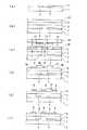
図2に示すように、第1の実施形態の製造方法は、透明絶縁基板1の上面に長方形状のゲート電極2を形成し(図2(a))、透明絶縁基板1とゲート電極2を覆うようにゲート絶縁膜3を形成し、ゲート絶縁膜3の上面にポジレジスト20を形成する(図2(b))。ここで、透明絶縁基板1の背面側からの露光(裏露光)(図2(c))および現像によって、ゲート電極2に自己整合したレジストパターン21を残す(図2(d))。
次に、金属ナノ粒子を含有する液体を、ソース電極形成部4aとチャネル部8とドレイン電極形成部5aを包含するパターンを用いてフレキソ印刷すると、液体はレジストパターン21に弾かれてゲート絶縁層上に流出する(図2(e))。ここで、低温(100℃程度)で仮焼成してソース電極4とドレイン電極5を仮形成した後、剥離液に浸けてレジストパターン21を除去する(図2(f))。その後、150℃程度の本焼成を行うことにより、ソース電極4とドレイン電極5を低抵抗化する。最後に、半導体層6を形成する(図2(g))。As shown in FIG. 2, in the manufacturing method of the first embodiment, a
Next, when the liquid containing the metal nanoparticles is flexographically printed using a pattern including the source
尚、レジストパターン21の形状(順テーパまたは逆テーパ)や幅の広狭などは、露光条件や現像条件によって制御することが可能である。
本発明の製造方法では、レジストパターン21が順テーパであってもソース電極およびドレイン電極を形成できる。
ソース電極形成部とはソース電極が形成される領域であり、ドレイン電極形成部とはドレイン電極が形成される領域である。また、チャネル部とは、平面視的配置においてソース電極4とドレイン電極5の間の領域であって、半導体層が形成される領域である。Note that the shape (forward taper or reverse taper) and width of the
In the manufacturing method of the present invention, the source electrode and the drain electrode can be formed even if the resist
The source electrode formation portion is a region where the source electrode is formed, and the drain electrode formation portion is a region where the drain electrode is formed. The channel portion is a region between the
(第2の実施形態)
図1の薄膜トランジスタを製造するための本発明の第2の実施形態を、以下に説明する。
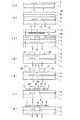
図3に示すように、第2の実施形態の製造方法は、透明絶縁基板1の上面に長方形状のゲート電極2を形成し(図3(a))、透明絶縁基板1とゲート電極2を覆うようにゲート絶縁膜3を形成し、ゲート絶縁膜3の上面にポジレジスト20を形成する(図3(b))。ここで、マスク10を用いた表パターン露光とマスク11を用いた裏パターン露光(図3(c))および現像によって、ゲート電極2に自己整合したレジストパターン21およびソース電極形成部4aとドレイン電極形成部5aを囲うレジストパターン22,23を残す(図3(d))。(Second Embodiment)
A second embodiment of the present invention for manufacturing the thin film transistor of FIG. 1 will be described below.
As shown in FIG. 3, in the manufacturing method of the second embodiment, a
このように露光するためには、裏露光としては、ゲート電極2を遮光部として露光する。これにより、平面視的配置においてゲート電極2と同一形状のレジストパターン21を形成する。また、表露光によるレジストパターン22,23の形成を阻害しないように、表露光のマスク10の遮光部13より若干大きな遮光部14を有するマスク11を用いる。表露光としては、ソース電極形成部4aとドレイン電極形成部5aを囲うレジストパターン22,23を形成するようにマスク10に遮光部13を形成しておく。また、裏露光によるレジストパターン21の形成を阻害しないように、ゲート電極2を囲うとともにゲート電極2より若干大きな遮光部13を有するマスク10を用いる。 In order to perform the exposure as described above, as the back exposure, the
続いて、ソース電極形成部4aとドレイン電極形成部5aに、金属ナノ粒子を含有する液体をディスペンサ等によって塗布する。このとき、液体がレジストパターン21上に塗布されることがあっても、レジストパターン21に弾かれてソース電極形成部4aとドレイン電極形成部5aに分離する(図3(e))。ここで、低温(100℃程度)で金属ナノ粒子を含む液体を仮焼成してソース電極4とドレイン電極5を仮形成した後、剥離液に浸けてレジストパターン21〜23を除去する(図3(f))。その後、150℃程度の本焼成を行うことにより、ソース電極4とドレイン電極5を低抵抗化する。最後に、半導体層6を形成する(図3(g))。 Subsequently, a liquid containing metal nanoparticles is applied to the source
尚、レジストパターン21の形状(順テーパまたは逆テーパ)や幅の広狭などは、露光条件や現像条件によって制御することが可能である。
また、レジストパターン22,23は、表露光パターンで形成する方が精度良く形成できるが、裏露光の遮光部のみで形成してもよい。Note that the shape (forward taper or reverse taper) and width of the resist
In addition, the resist
(第3の実施形態)
図4の薄膜トランジスタを製造するための本発明の第3の実施形態を、以下に説明する。
尚、図4の薄膜トランジスタ31は、透明絶縁基板1の上面にゲート電極2およびゲート配線7が形成され、透明絶縁基板1とゲート電極2とゲート配線7がゲート絶縁膜3で覆われている。ゲート絶縁膜3の上面には、半導体層6が形成され、半導体層6の上面には、ソース電極4およびドレイン電極5が形成されている。ソース電極4は円形に形成され、ドレイン電極5は、長方形の中心を円形にくり抜いた形状に形成されている。ゲート電極2は、等幅リング状に形成され、外周円上の一部にゲート配線7が連結されている。平面視的配置において、ソース電極4とドレイン電極5の間にゲート電極2が形成されているとともに、各電極の中心位置は略一致するように形成されている。(Third embodiment)
A third embodiment of the present invention for manufacturing the thin film transistor of FIG. 4 will be described below.
In the
図5に示すように、第3の実施形態の製造方法は、透明絶縁基板1の上面に、等幅リング状のゲート電極2およびゲート配線7を形成し(図5(a))、透明絶縁基板1とゲート電極2とゲート配線7を覆うようにゲート絶縁膜3を形成する。また、ゲート絶縁膜3の上面には半導体層6とポジレジスト20を順次形成する(図5(b))。次に、マスク10を用いた表パターン露光と裏露光(図5(c))および現像によって、ゲート配線上のポジレジストを除去し、ゲート電極2に自己整合したレジストパターン21のみを残す(図5(d))。 As shown in FIG. 5, in the manufacturing method of the third embodiment, a uniform-width ring-shaped
このように露光するためには、裏露光としては、ゲート電極2を遮光部として露光する。これにより、平面視的配置においてゲート電極2と同一形状のレジストパターン21を形成する。また、表露光としては、裏露光によるレジストパターン21の形成を阻害しないように、ゲート電極2を囲うとともにゲート電極2より若干大きな遮光部13を有するマスク10を用いる。 In order to perform the exposure as described above, as the back exposure, the
次に、金属ナノ粒子を含有する液体を、ソース電極形成部4aとチャネル部8とドレイン電極形成部5aを包含するパターンを用いてフレキソ印刷すると、液体はレジストパターン21に弾かれてソース電極形成部4aとドレイン電極形成部5aに分離する(図5(e))。ここで、低温(100℃程度)で仮焼成してソース電極4とドレイン電極5を仮形成した後、剥離液に浸けてレジストパターン21を除去する(図5(f))。その後、150℃程度の本焼成を行うことにより、ソース電極4とドレイン電極5を低抵抗化する。
尚、レジストパターン21の形状(順テーパまたは逆テーパ)や幅の広狭などは、露光条件や現像条件によって制御することが可能である。Next, when the liquid containing the metal nanoparticles is flexographically printed using a pattern including the source
Note that the shape (forward taper or reverse taper) and width of the resist
(第4の実施形態)
図4の薄膜トランジスタを製造するための本発明の第4の実施形態を、以下に説明する。
図6に示すように、透明絶縁基板1の上面に、等幅リング状のゲート電極2およびゲート配線7を形成し(図6(a))、その上にゲート絶縁膜3、半導体層6およびポジレジスト20を順次形成する(図6(b))。ここで、マスク10を用いた表パターン露光とマスク11を用いた裏パターン露光(図6(c))および現像によって、ゲート電極2に自己整合したレジストパターン21およびレジストパターン23を残す(図6(d))。(Fourth embodiment)
A fourth embodiment of the present invention for manufacturing the thin film transistor of FIG. 4 will be described below.
As shown in FIG. 6, a uniform-width ring-shaped
このように露光するためには、裏露光としては、ゲート電極2を遮光部として露光する。これにより、平面視的配置においてゲート電極2と同一形状のレジストパターン21を形成する。また、表露光によるレジストパターン23の形成を阻害しないように、形成するレジストパターン23を囲うとともにそれらより若干大きな遮光部14を有するマスク11を用いる。表露光としては、ソース電極形成部4aとドレイン電極形成部5aを囲うレジストパターン21,23を形成するようにマスク10を作成する。また、裏露光によるレジストパターン21の形成を阻害しないように、ゲート電極2を囲うとともにゲート電極2より若干大きな遮光部13を有するマスク10を用いる。 In order to perform the exposure as described above, as the back exposure, the
次に、ソース電極形成部4aおよびドレイン電極形成部5aに、金属ナノ粒子を含有する液体をディスペンサ等によって塗布する。このとき、液体がレジストパターン21上に塗布されることがあっても、レジストパターン21に弾かれてソース電極形成部4aとドレイン電極形成部5aに分離する(図6(e))。ここで、低温(100℃程度)で仮焼成してソース電極4とドレイン電極5を仮形成した後、剥離液に浸けてレジストパターン21,23を除去する(図6(f))。その後、150℃程度の本焼成を行うことにより、ソース電極4とドレイン電極5を低抵抗化する。
尚、レジストパターン21の形状(順テーパまたは逆テーパ)や幅の広狭などは、露光条件や現像条件によって制御することが可能である。Next, a liquid containing metal nanoparticles is applied to the source
Note that the shape (forward taper or reverse taper) and width of the resist
(第5の実施形態)
図7の薄膜トランジスタを製造するための本発明の第5の実施形態を、以下に説明する。
尚、図7の薄膜トランジスタ32は、透明絶縁基板1の上面にゲート電極2およびゲート配線7が形成され、絶縁基板1とゲート電極2とゲート配線7がゲート絶縁膜3で覆われている。ゲート絶縁膜3の上面には、ソース電極4とドレイン電極5と半導体層6が形成されている。ソース電極4は円形に形成され、ドレイン電極5は、長方形の中心を円形にくり抜いた形状に形成されている。ゲート電極2は、等幅リング状に形成され、外周円上の一部にゲート配線7が連結されている。ソース電極4とドレイン電極5の間には半導体層6が形成されている。半導体層6はゲート電極2と重なるように配置されている。すなわち、平面視的配置において、ソース電極4とドレイン電極5の間にゲート電極2が形成されていることになり、各電極の中心位置は略一致するように形成されている。(Fifth embodiment)
A fifth embodiment of the present invention for manufacturing the thin film transistor of FIG. 7 will be described below.
In the
図8に示すように、第5の実施形態の製造方法は、透明絶縁基板1の上面に、等幅リング状のゲート電極2およびゲート配線7を形成し(図8(a))、その上にゲート絶縁膜3、半導体層6およびポジレジスト20を順次形成する(図8(b))。ここで、マスク10を用いた表パターン露光と裏露光(図8(c))および現像によって、ゲート電極2に自己整合したレジストパターン21のみを残す(図8(d))。 As shown in FIG. 8, in the manufacturing method of the fifth embodiment, a uniform-width ring-shaped
このように露光するためには、裏露光としては、ゲート電極2を遮光部として露光する。これにより、平面視的配置においてゲート電極2と同一形状のレジストパターン21を形成する。表露光としては、裏露光によるレジストパターン21の形成を阻害しないように、ゲート電極2を囲うとともにゲート電極2より若干大きな遮光部13を有するマスク10を用いる。 In order to perform the exposure as described above, as the back exposure, the
次に、半導体層6をエッチングすることによって、レジストパターン21の下部のみにチャネル部8となる半導体層6を残す(図8(e))。その上に、金属ナノ粒子を含有する液体を、ソース電極形成部4aとチャネル部8とドレイン電極形成部5aを包含するパターンを用いてフレキソ印刷すると、液体はレジストパターン21に弾かれてソース電極形成部4aとドレイン電極形成部5aに分離する(図8(f))。ここで、低温(100℃程度)で仮焼成してソース電極4とドレイン電極5を仮形成した後、剥離液に浸けてレジストパターン21を除去する(図8(g))。その後、150℃程度の本焼成を行うことにより、ソース電極4とドレイン電極5を低抵抗化する。
尚、レジストパターン21の形状(順テーパまたは逆テーパ)や幅の広狭などは、露光条件や現像条件によって制御することが可能である。Next, the
Note that the shape (forward taper or reverse taper) and width of the resist
以上のように、本発明では、透明絶縁基板上にゲート電極を形成する工程と、前記透明絶縁基板と前記ゲート電極を覆うようにゲート絶縁膜を形成する工程と、半導体層を形成する工程と、レジストを塗布する工程と、裏露光によって前記ゲート電極に自己整合したレジストパターンを形成する工程と、ソース電極とドレイン電極を形成する工程と、レジストを除去する工程とを少なくとも有する薄膜トランジスタの製造方法であって、前記ソース電極とドレイン電極を形成する工程が、金属ナノ粒子を含む液体を塗布する工程を含むことを特徴とする。ただし、半導体層の形成は、ゲート絶縁膜の形成の次の工程であってもよいし、ソース電極4およびドレイン電極5を形成した後の工程であってもよい。半導体層6が酸化物である場合には前者が、有機物である場合には後者が好適に使用できるが、それに限定されるものではない。ゲート電極2の形状としては長方形状とリング状を示したが、これらに限定されるものではない。 As described above, in the present invention, a step of forming a gate electrode on a transparent insulating substrate, a step of forming a gate insulating film so as to cover the transparent insulating substrate and the gate electrode, and a step of forming a semiconductor layer A method of manufacturing a thin film transistor comprising at least a step of applying a resist, a step of forming a resist pattern self-aligned with the gate electrode by back exposure, a step of forming a source electrode and a drain electrode, and a step of removing the resist And the process of forming the said source electrode and a drain electrode includes the process of apply | coating the liquid containing a metal nanoparticle, It is characterized by the above-mentioned. However, the formation of the semiconductor layer may be a step subsequent to the formation of the gate insulating film, or may be a step after the
上記の液体を塗布する工程は、ソース電極4とチャネル部8とドレイン電極5を包含するパターンを用いてフレキソ印刷し、チャネル部8の液体がレジストパターンに弾かれてソース電極4とドレイン電極5に分離する工程であることが好ましい。
また、レジストとしては、疎水性を有するものが好ましく、水による接触角が大きければ大きいほど良いが、30°以上のものが使用可能である。例えばノボラック系ポジレジストは、水による接触角が40°〜80°程度であり、充分使用可能である。撥水剤(例えばシリコーン系やフッ素系)を混合して、接触角を90°以上にすると、さらに望ましい。また、下地層の水による接触角がレジスト20の水による接触角よりも小さいことが必要である。In the step of applying the liquid, flexographic printing is performed using a pattern including the
The resist preferably has hydrophobicity, and the larger the contact angle with water, the better. However, a resist of 30 ° or more can be used. For example, a novolac positive resist has a contact angle with water of about 40 ° to 80 ° and can be used sufficiently. It is more desirable to mix a water repellent (for example, silicone or fluorine) to make the contact angle 90 ° or more. Further, it is necessary that the contact angle of the underlayer with water is smaller than the contact angle of the resist 20 with water.
上記の裏露光は、ゲート電極以外に遮光部を有するマスクを用いたパターン露光であって、チャネル部8のレジストパターン21とともにソース電極形成部とドレイン電極形成部を形成するレジストパターン22,23も残し、ディスペンサ等によって液体を塗布してもよい。この場合、この二種類のレジストパターンの露光は、一括に同時に行ってもよく、又、別々に行ってもよい。 The above back exposure is pattern exposure using a mask having a light shielding portion in addition to the gate electrode, and the resist
金属ナノ粒子とは、粒径が1μm未満の金属粒子である。上記の金属ナノ粒子を含む液体の主成分は水であることが好ましい。ここで主成分が水であるとは、溶媒(即ち金属ナノ粒子は含まない)の50wt%以上が水であることを意味する。金属ナノ粒子としては、Ag、Ni、Au、Pt、Pd等が使用可能である。液体の主成分が水であることにより、レジスト21〜23を溶かすことなく、レジスト21に弾かれて良好な塗布形状が得られる。一方、有機溶剤が主成分であると、レジスト21を溶かしてしまい、良好な塗布が困難である。 Metal nanoparticles are metal particles having a particle size of less than 1 μm. The main component of the liquid containing the metal nanoparticles is preferably water. Here, the main component is water means that 50 wt% or more of the solvent (that is, the metal nanoparticles are not included) is water. As the metal nanoparticles, Ag, Ni, Au, Pt, Pd, or the like can be used. Since the main component of the liquid is water, it is repelled by the resist 21 without dissolving the resists 21 to 23, and a good coating shape is obtained. On the other hand, when the organic solvent is the main component, the resist 21 is dissolved, and good coating is difficult.
半導体としては、酸化物半導体や有機半導体を用いることができる。酸化物半導体としては、InGaZnO系、InZnO系、ZnGaO系、InGaO系、ZnO系、SnO系、あるいはこれらの混合物等が好適に使用され、有機半導体としては、ポリチオフェン誘導体、ポリフェニレンビニレン誘導体、ポリチエニレンビニレン誘導体、ポリアリルアミン誘導体、ポリアセチレン誘導体、アセン誘導体、オリゴチオフェン誘導体等が好適に使用される。 As the semiconductor, an oxide semiconductor or an organic semiconductor can be used. As the oxide semiconductor, InGaZnO-based, InZnO-based, ZnGaO-based, InGaO-based, ZnO-based, SnO-based, or a mixture thereof is preferably used, and as the organic semiconductor, polythiophene derivatives, polyphenylene vinylene derivatives, polythienylenes are used. Vinylene derivatives, polyallylamine derivatives, polyacetylene derivatives, acene derivatives, oligothiophene derivatives and the like are preferably used.
酸化物半導体を用いて半導体層を形成する場合には、スパッタやレーザアブレーションによる成膜が好適に使用できる。また、有機金属化学気相成長や、原料の塗布・焼成も使用できる。有機半導体を用いて半導体層を形成する場合には、原料の塗布・焼成が好適に使用できる。 In the case where a semiconductor layer is formed using an oxide semiconductor, film formation by sputtering or laser ablation can be preferably used. Also, metal organic chemical vapor deposition and coating / firing of raw materials can be used. In the case of forming a semiconductor layer using an organic semiconductor, coating and baking of raw materials can be preferably used.
酸化物半導体や有機半導体は、室温あるいは200℃以下での低温成膜が可能なので、透明絶縁基板1としてプラスチック材料(ポリエチレンテレフタレート(PET)等)が使用できる。 Since oxide semiconductors and organic semiconductors can be formed at room temperature or at a low temperature of 200 ° C. or lower, a plastic material (polyethylene terephthalate (PET) or the like) can be used as the transparent insulating
ゲート電極2としては、Al、Cr、Au、Ag、Cu、Ti、Ni等の金属が使用できる。ゲート絶縁層3としては、SiO2、Al2O3、SiN、Ta2O5、Y2O3等の無機物や、エポキシ等の有機物を用いることができる。As the
(実施例1)
本発明の第1の実施例について、図2を用いて説明する。基板1として、厚さ100μmのポリエチレンテレフタレート(PET)を用意し、Alをスパッタ成膜、フォトリソおよびエッチングによって長方形のゲート電極2を作製した(図2(a))。厚さは100nm、ゲート長さは300μm、幅は5μmとした。次に、スピンコートおよび焼成によってエポキシからなるゲート絶縁膜3およびポジレジスト20を成膜した(図2(b))。ゲート絶縁膜3の厚さは500nm、ポジレジスト20の厚さは5μmとした。Example 1
A first embodiment of the present invention will be described with reference to FIG. Polyethylene terephthalate (PET) having a thickness of 100 μm was prepared as the
次に、裏露光(図2(c))および現像によって、ゲート電極2に自己整合したレジストパターン21を残した(図2(d))。その後、Agナノ粒子を含有する液体のフレキソ印刷によって、ソース電極4とドレイン電極5を形成した(図2(e))。100℃での仮焼成の後、レジストパターン21を剥離液で除去し(図2(f))、150℃の本焼成によって厚さ300nmのソース電極4とドレイン電極5を形成した。最後に、ポリチオフェン誘導体溶液をディスペンスおよび焼成によって半導体層6を形成した(図2(g))。 Next, a resist
(実施例2)
本発明の第2の実施例について、図3を用いて説明する。基板1として、厚さ100μmのポリエチレンテレフタレート(PET)を用意し、Alをスパッタ成膜、フォトリソおよびエッチングによって長方形のゲート電極2を作製した(図3(a))。厚さは100nm、ゲート長さは300μm、幅は5μmとした。次に、スピンコートおよび焼成によってエポキシからなるゲート絶縁膜3およびポジレジスト20を成膜した(図3(b))。ゲート絶縁膜3の厚さは500nm、ポジレジスト20の厚さは5μmとした。(Example 2)
A second embodiment of the present invention will be described with reference to FIG. Polyethylene terephthalate (PET) having a thickness of 100 μm was prepared as the
次に、表パターン露光と裏パターン露光(図3(c))および現像によって、ゲート電極2に自己整合したレジストパターン21およびソース電極形成部4aとドレイン電極形成部5aを形成するレジストパターン22,23を残した(図3(d))。その後、Agナノ粒子を含有する液体のディスペンスによって、ソース電極4とドレイン電極5を形成した(図3(e))。100℃での仮焼成の後、レジストパターン21〜23を剥離液で除去し(図3(f))、150℃の本焼成によって厚さ300nmのソース電極4とドレイン電極5を形成した。最後に、ポリチオフェン誘導体溶液をディスペンスおよび焼成によって半導体層6を形成した(図3(g))。 Next, a resist
(実施例3)
本発明の第3の実施例について、図5を用いて説明する。基板1として、厚さ100μmのポリエチレンテレフタレート(PET)を用意し、Alをスパッタ成膜、フォトリソおよびエッチングによってリング状のゲート電極2およびゲート配線7を作製した(図5(a))。ゲート電極の厚さは100nm、外径は300μm、内径は290μmとした。次に、スパッタによってゲート絶縁膜3としてSiO2、半導体層6としてInGaZnO4を成膜し、スピンコートによってポジレジスト20を成膜した(図5(b))。ゲート絶縁膜3の厚さは500nm、半導体層6の厚さは200nm、およびレジスト20の厚さは5μmとした。(Example 3)
A third embodiment of the present invention will be described with reference to FIG. As the
次に、表パターン露光と裏露光(図5(c))および現像によって、ゲート電極2に自己整合したレジストパターン21を残した(図5(d))。そして、Agナノ粒子を含有する液体のフレキソ印刷によって、ソース電極4とドレイン電極5を形成した(図5(e))。100℃での仮焼成の後、レジストパターン21を剥離液で除去し(図5(f))、150℃の本焼成によって厚さ300nmのソース電極4とドレイン電極5を形成した。 Next, a resist
(実施例4)
本発明の第4の実施例について、図6を用いて説明する。基板1として、厚さ100μmのポリエチレンテレフタレート(PET)を用意し、Alをスパッタ成膜、フォトリソおよびエッチングによってリング状のゲート電極2を作製した(図7(a))。ゲート電極の厚さは100nm、外径は300μm、内径は290μmとした。
次に、スパッタによってゲート絶縁膜3としてSiO2、半導体層6としてInGaZnO4を成膜し、スピンコートによってポジレジスト20を成膜した(図7(b))。ゲート絶縁膜3の厚さは500nm、半導体層6の厚さは200nm、レジスト20の厚さは5μmとした。(Example 4)
A fourth embodiment of the present invention will be described with reference to FIG. Polyethylene terephthalate (PET) having a thickness of 100 μm was prepared as the
Next, SiO2 was formed as the
次に、表パターン露光と裏パターン露光(図7(c))および現像によって、ゲート電極2に自己整合したレジストパターン21およびドレイン電極形成部を形成するレジストパターン23を残した(図7(d))。そして、Agナノ粒子を含有する液体のディスペンスによって、ソース電極4とドレイン電極5を形成した(図7(e))。100℃での仮焼成の後、レジストパターン21,23を剥離液で除去し(図7(f))、150℃の本焼成によって厚さ300nmのソース電極4とドレイン電極5を形成した。 Next, a resist
(実施例5)
本発明の第5の実施例について、図8を用いて説明する。基板1として、厚さ100μmのポリエチレンテレフタレート(PET)を用意し、Alをスパッタ成膜、フォトリソおよびエッチングによってリング状のゲート電極2およびゲート配線7を作製した(図8(a))。ゲート電極の厚さは100nm、外径は300μm、内径は290μmである。(Example 5)
A fifth embodiment of the present invention will be described with reference to FIG. Polyethylene terephthalate (PET) having a thickness of 100 μm was prepared as the
次に、スパッタによってゲート絶縁膜3としてSiO2、半導体層6としてInGaZnO4を成膜し、スピンコートによってレジスト20を成膜した(図8(b))。ゲート絶縁膜3の厚さは500nm、半導体層6の厚さは200nm、ポジレジスト20の厚さは5μmとした。次に、表パターン露光と裏露光(図8(c))および現像によって、ゲート電極2に自己整合したレジストパターン21を残した(図8(d))。ここで、ウェットエッチングによって半導体層6をエッチングした(図8(e))。そして、Agナノ粒子を含有する液体のフレキソ印刷によって、ソース電極4とドレイン電極5を形成した(図8(f))。100℃での仮焼成の後、レジストパターン21を剥離液で除去し(図8(g))、150℃の本焼成によって厚さ300nmのソース電極4とドレイン電極5を形成した。Next, SiO2 was formed as the
上記の実施例1〜5の製造方法で作製した薄膜トランジスタにおいて、ゲート電極とソース電極およびドレイン電極との平面視的配置における重なり幅を測定したところ、いずれの実施例においても1μm以下であった。また、ゲート電極とソース電極およびドレイン電極とが重ならず、離れている場合においても、その離間距離は1μm以下であった。 In the thin film transistors manufactured by the manufacturing methods of Examples 1 to 5, the overlapping width in the planar arrangement of the gate electrode, the source electrode, and the drain electrode was measured and found to be 1 μm or less in any of the examples. Further, even when the gate electrode and the source electrode and the drain electrode do not overlap and are separated from each other, the separation distance is 1 μm or less.
1・・・透明絶縁基板、2・・・ゲート電極、3・・・ゲート絶縁膜、4・・・ソース電極、4a・・・ソース電極形成部、5・・・ドレイン電極、5a・・・ドレイン電極形成部、6・・・半導体層、7・・・ゲート配線、8・・・チャネル部、10,11・・・フォトマスク、12・・・紫外線、13,14・・・遮光部、20・・・ポジレジスト、21〜23・・・レジストパターン、30,31,32,40・・・薄膜トランジスタ
DESCRIPTION OF
Claims (5)
Translated fromJapanese前記ソース電極とドレイン電極を形成する工程が、金属ナノ粒子を含む液体を塗布する工程を含み、
ソース電極形成部とドレイン電極形成部との境界部分にレジストパターンを形成し、その上から前記金属ナノ粒子を含む液体を前記ソース電極形成部と前記ドレイン電極形成部を含むように塗布し、前記レジストパターンの前記液体を弾く力を利用して前記液体を前記ソース電極形成部と前記ドレイン電極形成部に区分けしてソース電極とドレイン電極を形成する
ことを特徴とする薄膜トランジスタの製造方法。Forming a gate electrode on the transparent insulating substrate; forming a gate insulating film so as to cover the transparent insulating substrate and the gate electrode; forming a semiconductor layer; applying a resist; A method of manufacturing a thin film transistor comprising at least a step of forming a resist pattern self-aligned with the gate electrode by exposure, a step of forming a source electrode and a drain electrode, and a step of removing the resist,
The step of forming the source electrode and the drain electrode,viewed contains the step of applying a liquid containing metalnanoparticles,
A resist pattern is formed at a boundary portion between the source electrode formation portion and the drain electrode formation portion, and a liquid containing the metal nanoparticles is applied thereon so as to include the source electrode formation portion and the drain electrode formation portion, A manufacturing method of a thin film transistor,wherein a source electrode and a drain electrode are formed by dividing theliquid into the source electrode forming portion and the drain electrode forming portion using a force of repelling the liquid of a resist pattern. Method.
Priority Applications (1)
| Application Number | Priority Date | Filing Date | Title |
|---|---|---|---|
| JP2005101404AJP4984416B2 (en) | 2005-03-31 | 2005-03-31 | Thin film transistor manufacturing method |
Applications Claiming Priority (1)
| Application Number | Priority Date | Filing Date | Title |
|---|---|---|---|
| JP2005101404AJP4984416B2 (en) | 2005-03-31 | 2005-03-31 | Thin film transistor manufacturing method |
Publications (2)
| Publication Number | Publication Date |
|---|---|
| JP2006286719A JP2006286719A (en) | 2006-10-19 |
| JP4984416B2true JP4984416B2 (en) | 2012-07-25 |
Family
ID=37408331
Family Applications (1)
| Application Number | Title | Priority Date | Filing Date |
|---|---|---|---|
| JP2005101404AExpired - Fee RelatedJP4984416B2 (en) | 2005-03-31 | 2005-03-31 | Thin film transistor manufacturing method |
Country Status (1)
| Country | Link |
|---|---|
| JP (1) | JP4984416B2 (en) |
Families Citing this family (9)
| Publication number | Priority date | Publication date | Assignee | Title |
|---|---|---|---|---|
| JP5458296B2 (en)* | 2006-10-27 | 2014-04-02 | 国立大学法人岩手大学 | MICRO-PROCESSED STRUCTURE, PROCESSING METHOD THEREOF, ELECTRONIC DEVICE, AND MANUFACTURING METHOD THEREOF |
| JP5216204B2 (en) | 2006-10-31 | 2013-06-19 | 株式会社半導体エネルギー研究所 | Liquid crystal display device and manufacturing method thereof |
| JP5105842B2 (en) | 2006-12-05 | 2012-12-26 | キヤノン株式会社 | Display device using oxide semiconductor and manufacturing method thereof |
| JP2009206388A (en)* | 2008-02-29 | 2009-09-10 | Toyama Univ | Thin film transistor, and manufacturing method thereof |
| TWI508282B (en)* | 2008-08-08 | 2015-11-11 | Semiconductor Energy Lab | Semiconductor device and method of manufacturing same |
| TWI606595B (en)* | 2008-11-07 | 2017-11-21 | 半導體能源研究所股份有限公司 | Semiconductor device and method of manufacturing same |
| KR101717460B1 (en)* | 2009-10-16 | 2017-03-17 | 가부시키가이샤 한도오따이 에네루기 켄큐쇼 | Liquid crystal display device and electronic device including the liquid crystal display device |
| WO2011068025A1 (en)* | 2009-12-04 | 2011-06-09 | Semiconductor Energy Laboratory Co., Ltd. | Dc converter circuit and power supply circuit |
| JP2013218337A (en)* | 2013-04-25 | 2013-10-24 | Semiconductor Energy Lab Co Ltd | Display device, display module, and electronic apparatus |
Family Cites Families (18)
| Publication number | Priority date | Publication date | Assignee | Title |
|---|---|---|---|---|
| JP3105606B2 (en)* | 1991-12-25 | 2000-11-06 | 富士通株式会社 | Liquid crystal device manufacturing method |
| JP2838943B2 (en)* | 1992-07-07 | 1998-12-16 | 日本電気株式会社 | Method for manufacturing thin film transistor |
| JPH08162477A (en)* | 1994-12-02 | 1996-06-21 | Fujitsu Ltd | Method for manufacturing semiconductor device |
| JP2576436B2 (en)* | 1995-02-15 | 1997-01-29 | 株式会社日立製作所 | Liquid crystal display |
| JPH0936372A (en)* | 1995-07-19 | 1997-02-07 | Sharp Corp | Method for manufacturing semiconductor device |
| JPH1084115A (en)* | 1996-09-09 | 1998-03-31 | Fujitsu Ltd | Thin film transistor, manufacturing method thereof and liquid crystal display device |
| US6734029B2 (en)* | 2000-06-30 | 2004-05-11 | Seiko Epson Corporation | Method for forming conductive film pattern, and electro-optical device and electronic apparatus |
| JP3980312B2 (en)* | 2001-09-26 | 2007-09-26 | 株式会社日立製作所 | Liquid crystal display device and manufacturing method thereof |
| JP3970583B2 (en)* | 2001-11-22 | 2007-09-05 | 株式会社東芝 | Semiconductor device and manufacturing method thereof |
| JP2003258256A (en)* | 2002-02-27 | 2003-09-12 | Konica Corp | Organic TFT device and manufacturing method thereof |
| JP2004146430A (en)* | 2002-10-22 | 2004-05-20 | Konica Minolta Holdings Inc | Organic thin film transistor, organic TFT device, and method of manufacturing the same |
| JP4554881B2 (en)* | 2002-11-08 | 2010-09-29 | 旭化成株式会社 | Manufacturing method of organic semiconductor element |
| JP2004241758A (en)* | 2003-01-17 | 2004-08-26 | Advanced Lcd Technologies Development Center Co Ltd | Method of forming wiring metal layer and wiring metal layer |
| JP2004273514A (en)* | 2003-03-05 | 2004-09-30 | Konica Minolta Holdings Inc | Organic thin film transistor and method of manufacturing the same |
| JP2004335572A (en)* | 2003-05-01 | 2004-11-25 | Seiko Epson Corp | Coating device, thin film forming device, semiconductor device manufacturing method, electro-optical device, and electronic equipment |
| JP4325479B2 (en)* | 2003-07-17 | 2009-09-02 | セイコーエプソン株式会社 | Organic transistor manufacturing method, active matrix device manufacturing method, display device manufacturing method, and electronic device manufacturing method |
| JP2005072528A (en)* | 2003-08-28 | 2005-03-17 | Shin Etsu Chem Co Ltd | Thin-layer field effect transistor and manufacturing method thereof |
| JP2006269709A (en)* | 2005-03-24 | 2006-10-05 | Hitachi Ltd | Manufacturing method of semiconductor device having organic thin film transistor |
- 2005
- 2005-03-31JPJP2005101404Apatent/JP4984416B2/ennot_activeExpired - Fee Related
Also Published As
| Publication number | Publication date |
|---|---|
| JP2006286719A (en) | 2006-10-19 |
Similar Documents
| Publication | Publication Date | Title |
|---|---|---|
| US9202683B2 (en) | Printed material constrained by well structures and devices including same | |
| JP6437574B2 (en) | THIN FILM TRANSISTOR AND METHOD FOR MANUFACTURING SAME, ARRAY SUBSTRATE, AND DISPLAY DEVICE | |
| CN101582391B (en) | Method for forming a pattern, method for manufacturing semiconductor apparatus, and method for manufacturing display | |
| JP2009272523A (en) | Thin-film transistor, and method of manufacturing the same | |
| US20130328049A1 (en) | Thin-film transistor substrate and method of manufacturing the same | |
| JP4984416B2 (en) | Thin film transistor manufacturing method | |
| JP6073880B2 (en) | Method for forming top gate type transistor | |
| KR20110036672A (en) | Method for manufacturing semiconductor device | |
| JP4622630B2 (en) | Thin film transistor manufacturing method | |
| JP2010283240A (en) | Thin film patterning method, device and manufacturing method thereof | |
| JP2010080552A (en) | Method for manufacturing transistor | |
| JP2015233044A (en) | Organic semiconductor element manufacturing method and organic semiconductor element | |
| KR101211216B1 (en) | method for fabricating of metal wiring, flat display device fabricated using the same and method for fabricating of flat display device using the same | |
| JP5375058B2 (en) | Thin film transistor array and manufacturing method thereof | |
| CN112420927B (en) | Organic thin film transistor device preparation method and display panel | |
| JP6649765B2 (en) | Thin film transistor and method of manufacturing thin film transistor | |
| US20080230771A1 (en) | Thin film transistor and method for manufacturing the same | |
| JP2008153354A (en) | Method for forming organic semiconductor pattern and method for manufacturing semiconductor device | |
| JP2009302441A (en) | Organic tft | |
| JP6627437B2 (en) | Method of manufacturing thin film transistor array substrate | |
| JP6612690B2 (en) | LAMINATED WIRING MEMBER, MANUFACTURING METHOD FOR LAMINATED WIRING MEMBER, THIN FILM TRANSISTOR AND ELECTRONIC DEVICE | |
| WO2007119795A1 (en) | Electronic device, electronic device manufacturing method and organic el display apparatus | |
| JP5200408B2 (en) | Thin film transistor manufacturing method | |
| JP2010021402A (en) | Organic TFT | |
| KR20100075061A (en) | Organic thin film transistor, and manufacturing method thereof |
Legal Events
| Date | Code | Title | Description |
|---|---|---|---|
| A621 | Written request for application examination | Free format text:JAPANESE INTERMEDIATE CODE: A621 Effective date:20080226 | |
| A977 | Report on retrieval | Free format text:JAPANESE INTERMEDIATE CODE: A971007 Effective date:20110623 | |
| A131 | Notification of reasons for refusal | Free format text:JAPANESE INTERMEDIATE CODE: A131 Effective date:20110628 | |
| A521 | Request for written amendment filed | Free format text:JAPANESE INTERMEDIATE CODE: A523 Effective date:20110824 | |
| A131 | Notification of reasons for refusal | Free format text:JAPANESE INTERMEDIATE CODE: A131 Effective date:20111101 | |
| A521 | Request for written amendment filed | Free format text:JAPANESE INTERMEDIATE CODE: A523 Effective date:20111220 | |
| TRDD | Decision of grant or rejection written | ||
| A01 | Written decision to grant a patent or to grant a registration (utility model) | Free format text:JAPANESE INTERMEDIATE CODE: A01 Effective date:20120403 | |
| A01 | Written decision to grant a patent or to grant a registration (utility model) | Free format text:JAPANESE INTERMEDIATE CODE: A01 | |
| A61 | First payment of annual fees (during grant procedure) | Free format text:JAPANESE INTERMEDIATE CODE: A61 Effective date:20120416 | |
| R150 | Certificate of patent or registration of utility model | Free format text:JAPANESE INTERMEDIATE CODE: R150 | |
| FPAY | Renewal fee payment (event date is renewal date of database) | Free format text:PAYMENT UNTIL: 20150511 Year of fee payment:3 | |
| LAPS | Cancellation because of no payment of annual fees |