JP4983682B2 - Object detection method, object detection apparatus, object detection program, and printing apparatus - Google Patents
Object detection method, object detection apparatus, object detection program, and printing apparatusDownload PDFInfo
- Publication number
- JP4983682B2 JP4983682B2JP2008079362AJP2008079362AJP4983682B2JP 4983682 B2JP4983682 B2JP 4983682B2JP 2008079362 AJP2008079362 AJP 2008079362AJP 2008079362 AJP2008079362 AJP 2008079362AJP 4983682 B2JP4983682 B2JP 4983682B2
- Authority
- JP
- Japan
- Prior art keywords
- determination
- determined
- detection
- face
- detection window
- Prior art date
- Legal status (The legal status is an assumption and is not a legal conclusion. Google has not performed a legal analysis and makes no representation as to the accuracy of the status listed.)
- Expired - Fee Related
Links
- 238000001514detection methodMethods0.000titleclaimsdescription259
- 238000012545processingMethods0.000claimsdescription47
- 238000013459approachMethods0.000claimsdescription5
- 238000000034methodMethods0.000description176
- 238000013528artificial neural networkMethods0.000description27
- 238000004364calculation methodMethods0.000description17
- 238000012986modificationMethods0.000description11
- 230000004048modificationEffects0.000description11
- 238000012937correctionMethods0.000description5
- 230000001174ascending effectEffects0.000description4
- 238000003672processing methodMethods0.000description4
- 238000006243chemical reactionMethods0.000description2
- 238000004891communicationMethods0.000description2
- 238000010586diagramMethods0.000description2
- 230000006870functionEffects0.000description2
- 239000000284extractSubstances0.000description1
- 230000001815facial effectEffects0.000description1
- 238000012886linear functionMethods0.000description1
- 238000005457optimizationMethods0.000description1
- 210000000056organAnatomy0.000description1
- 230000000644propagated effectEffects0.000description1
- 238000012706support-vector machineMethods0.000description1
Images


Landscapes
- Color, Gradation (AREA)
- Image Processing (AREA)
- Image Analysis (AREA)
Description
Translated fromJapanese本発明は、オブジェクト検出方法、オブジェクト検出装置、オブジェクト検出プログラムおよび印刷装置に関し、特に画像に含まれるオブジェクトを検出するオブジェクト検出方法、オブジェクト検出装置、オブジェクト検出プログラムおよび印刷装置に関する。 The present invention relates to an object detection method, an object detection apparatus, an object detection program, and a printing apparatus, and more particularly to an object detection method, an object detection apparatus, an object detection program, and a printing apparatus that detect an object included in an image.
画像データに含まれる顔画像を検出し、その検出結果を利用して、印刷処理や補正処理や画像入力機器の動作制御が行われている。検出窓を画像データのあらゆる位置に移動させながら、検出窓において顔画像が存在するか否かを判定していくことにより、画像データにおける不特定の位置に存在する顔画像を検出することができる(特許文献1、参照。)かかる文献(図6、参照。)においては、画像データの隅から順に検出窓を移動させている。
検出窓において顔画像が存在するか否かを判定するための処理負担は小さいものでないため、検出窓を画像データのあらゆる位置に移動させることにより、全体の検出処理の処理負担は大きくなるという問題があった。画像データのすべての位置(画素)について検出窓を設定すれば、検出漏れを防止することができるが、処理負担が著しく増大してしまう。逆に、画像データの一部の位置(画素)のみについて検出窓を設定すれば、処理負担を軽減することができるが、検出漏れが発生してしまう。 Since the processing load for determining whether or not a face image exists in the detection window is not small, moving the detection window to any position in the image data increases the processing load for the entire detection process. was there. If detection windows are set for all positions (pixels) of image data, omission of detection can be prevented, but the processing load increases remarkably. On the contrary, if the detection window is set only for a part of the position (pixels) of the image data, the processing load can be reduced, but a detection failure occurs.
本発明は、前記課題にかんがみてなされたもので、効率よく、かつ、漏れのないオブジェクトを検出するオブジェクト検出方法、オブジェクト検出装置、オブジェクト検出プログラムおよび印刷装置の提供を目的とする。 The present invention has been made in view of the above problems, and an object thereof is to provide an object detection method, an object detection device, an object detection program, and a printing device that detect an object efficiently and without omission.
上記課題を解決するために、本発明は、画像データが示す画像からオブジェクトを検出するにあたり、まず前記画像データに設定された検出窓の内側にオブジェクトが存在するか否かを判定する第1判定手段および第2判定手段を用意する。前記画像データにおける複数の位置に設定された前記検出窓について前記第1判定手段による判定を実行させる。そして、前記第1判定手段によってオブジェクトが存在すると判定された位置同士の間の複数の位置の前記検出窓については、前記第2判定手段による判定を実行させる。すなわち、前記第1判定手段によってオブジェクトが存在すると判定された位置同士の間の位置の前記検出窓においては、前記オブジェクトが存在する可能性が高いと考えることができるため、前記第2判定手段を実行させるようにする。反対に、前記第1判定手段によってオブジェクトが存在しないと判定された位置同士の間の位置の前記検出窓については、前記第2判定手段による判定を実行させないようにする。すなわち、前記第1判定手段によってオブジェクトが存在しないと判定された位置同士の間の位置の前記検出窓においては、前記オブジェクトが存在する可能性が低いと考えることができるため、前記第2判定手段を実行させないようにしても、検出漏れが生じる可能性は低い。 In order to solve the above-described problems, the present invention first determines whether or not an object exists inside a detection window set in the image data when detecting an object from an image indicated by the image data. Means and second determination means are prepared. Determination by the first determination unit is executed for the detection windows set at a plurality of positions in the image data. And about the said detection window of the several position between the positions determined that the object exists by the said 1st determination means, the determination by a said 2nd determination means is performed. That is, since it can be considered that the object is likely to exist in the detection window at the position between the positions where the object is determined to be present by the first determining means, the second determining means is Let it run. On the other hand, the determination by the second determination unit is not performed for the detection window at a position between the positions determined by the first determination unit that the object does not exist. That is, since it can be considered that there is a low possibility that the object exists in the detection window at a position between positions where it is determined that the object does not exist by the first determination unit, the second determination unit Even if the control is not executed, there is a low possibility of detection omission.
さらに、前記第1判定手段によってオブジェクトが存在すると判定された位置と前記第1判定手段によってオブジェクトが存在しないと判定された位置の間の位置においては、前記第1判定手段によってオブジェクトが存在しないと判定された位置よりも前記第1判定手段によってオブジェクトが存在すると判定された位置に近い位置を優先させて前記検出窓を設定し、当該設定した前記検出窓について前記第2判定手段による判定を実行させる。このように、すべての位置について前記第1判定手段と前記第2判定手段による判定を実行させるのではなく、予め前記第2判定手段の結果に応じて絞り込まれた位置について前記第2判定手段による判定を実行させるため、効率的なオブジェクト検出を実現させることができる。なお、前記オブジェクトは、特定の画像的特徴を有するものであればよく、例えば人物・動物の顔や顔器官等を検出することができる。 Further, if there is no object by the first determination means at a position between the position where the first determination means determines that the object exists and the position where the first determination means determines that the object does not exist. The detection window is set by giving priority to a position closer to the position where the object is determined to be present by the first determination means than the determined position, and the determination by the second determination means is executed for the set detection window Let In this way, the determination by the first determination unit and the second determination unit is not executed for all positions, but the second determination unit is used for the positions that are narrowed down in advance according to the result of the second determination unit. Since the determination is executed, efficient object detection can be realized. The object only needs to have a specific image characteristic. For example, a face of a person / animal or a facial organ can be detected.
さらに、前記第1判定手段によってオブジェクトが存在しないと判定された位置よりも前記第1判定手段によってオブジェクトが存在すると判定された位置に近い位置を優先させる具体的手法の一例として、以下の手法を採用することができる。すなわち、前記第1判定手段によってオブジェクトが存在すると判定された位置から前記第1判定手段によってオブジェクトが存在しないと判定された位置に近づくように順に前記検出窓を移動させながら前記第2判定手段による判定を実行させる。これにより、オブジェクトが存在する可能性が高いと考えられる位置から順に前記検出窓を移動させることができる。さらに、このように前記検出窓を移動させる際に、前記第2判定手段によってオブジェクトが存在しないと最初に判定された位置から前記第1判定手段によってオブジェクトが存在しないと判定された位置との間の位置については前記第2判定手段による判定を実行させないようにする。すなわち、前記第2判定手段によってオブジェクトが存在しないと最初に判定された位置よりも、前記第1判定手段によってオブジェクトが存在しないと判定された位置に近い側においては、オブジェクトが存在する可能性が低いと考えられる。このような位置については、検出漏れが生じる可能性が低いため、前記第2判定手段の判定を行わないようにする。 Furthermore, as an example of a specific method for giving priority to a position close to a position determined by the first determination means to be present rather than a position determined by the first determination means to be absent, the following technique is used: Can be adopted. That is, by the second determination means while moving the detection window in order so as to approach the position determined by the first determination means that the object does not exist from the position determined by the first determination means to be present. Make a decision. Thereby, the detection window can be moved in order from the position where the possibility that the object exists is high. Further, when moving the detection window in this way, between the position where the second determination means first determines that no object exists and the position where the first determination means determines that no object exists. For the position of, the determination by the second determination means is not executed. That is, there is a possibility that the object exists on the side closer to the position where the first determination means determines that the object does not exist than the position where the second determination means first determines that the object does not exist. It is considered low. Since such a position is unlikely to cause a detection omission, the determination by the second determination unit is not performed.
なお、前記第1判定手段と前記第2判定手段の判定特性の好適な例として、前記第1判定手段よりも前記第2判定手段の方が前記検出窓に対するオブジェクトの位置についての判定精度が高く、かつ、前記第2判定手段よりも前記第1判定手段の方が前記検出窓に対するオブジェクトの位置の変動に対するロバスト性が高いものを適用するのが望ましい。このようにすることにより、まず前記第1判定手段によって、オブジェクトが存在しそうな位置を大まかに絞り込み、その後、オブジェクトが存在しそうな位置について厳密に前記第2判定手段による判定を実行させることができる。 As a preferable example of the determination characteristics of the first determination unit and the second determination unit, the second determination unit has a higher determination accuracy with respect to the position of the object with respect to the detection window than the first determination unit. In addition, it is preferable that the first determination unit is more robust than the second determination unit with respect to a change in the position of the object with respect to the detection window. By doing so, first, the position where the object is likely to exist can be roughly narrowed down by the first determination means, and then the position where the object is likely to exist can be strictly determined by the second determination means. .
さらに、前記第1判定手段と前記第2判定手段として好適なものの別の例として、前記第2判定手段よりも前記第1判定手段の方が同一の前記検出窓について判定を実行させた場合の処理負担が少ないものを適用してもよい。前記第2判定手段における処理負担は大きいものであるが、上述したように前記第2判定手段を実行させる前記検出窓の位置は絞り込まれているため、処理を効率的なものとすることができる。 Further, as another example of the first determination unit and the second determination unit, the first determination unit performs determination on the same detection window as compared to the second determination unit. You may apply the thing with little processing burden. Although the processing load on the second determination unit is large, as described above, the position of the detection window for executing the second determination unit is narrowed down, so that the processing can be made efficient. .
以上においては、前記第2判定手段を実行させる前記検出窓の位置を絞り込む態様のものを説明したが、同様に前記第2判定手段を実行させる前記検出窓のサイズを絞り込むようにしてもよい。すなわち、前記画像データにおける複数のサイズに設定された前記検出窓について前記第1判定手段による判定を実行させる。そして、前記第1判定手段によってオブジェクトが存在すると判定されたサイズ同士の間の複数のサイズの前記検出窓については、前記第2判定手段による判定を実行させる。すなわち、前記第1判定手段によってオブジェクトが存在すると判定されたサイズ同士の間のサイズの前記検出窓においては、サイズがマッチする前記オブジェクトが存在する可能性が高いと考えることができるため、前記第2判定手段を実行させるようにする。反対に、前記第1判定手段によってオブジェクトが存在しないと判定されたサイズ同士の間のサイズの前記検出窓については、前記第2判定手段による判定を実行させないようにする。すなわち、前記第1判定手段によってオブジェクトが存在しないと判定されたサイズ同士の間のサイズの前記検出窓においては、サイズがマッチする前記オブジェクトが存在する可能性が低いと考えることができるため、前記第2判定手段を実行させないようにしても、検出漏れが生じる可能性は低い。 In the above description, the aspect of narrowing down the position of the detection window for executing the second determination unit has been described. However, the size of the detection window for executing the second determination unit may be similarly narrowed down. That is, the determination by the first determination unit is executed for the detection windows set to a plurality of sizes in the image data. And about the said detection window of the several size between the sizes determined that the object exists by the said 1st determination means, the determination by a said 2nd determination means is performed. That is, in the detection window having a size between the sizes determined by the first determination unit as being present, it can be considered that there is a high possibility that the object having a matching size exists. 2 The determination means is executed. On the other hand, the determination by the second determination unit is not executed for the detection window having a size between the sizes determined by the first determination unit as having no object. In other words, in the detection window having a size between the sizes determined by the first determination means that no object exists, it can be considered that there is a low possibility that the object having a matching size exists. Even if the second determination means is not executed, the possibility of detection omission is low.
さらに、前記第1判定手段によってオブジェクトが存在すると判定された大きさと前記第1判定手段によってオブジェクトが存在しないと判定された大きさの間の大きさにおいては、前記第1判定手段によってオブジェクトが存在しないと判定された大きさよりも前記第1判定手段によってオブジェクトが存在すると判定された大きさに近い大きさを優先させて前記検出窓を設定し、当該設定した前記検出窓について前記第2判定手段による判定を実行させる。このように、すべての大きさについて前記第1判定手段と前記第2判定手段による判定を実行させるのではなく、予め前記第1判定手段の結果に応じて絞り込まれた大きさについて前記第2判定手段による判定を実行させるため、効率的なオブジェクト検出を実現させることができる。 Furthermore, the object exists by the first determination means between the size determined by the first determination means and the size determined by the first determination means that the object does not exist. The detection window is set by prioritizing the size close to the size determined by the first determination means to be larger than the size determined not to be present, and the second determination means for the set detection window Make a decision based on. In this way, the second determination is not performed for the sizes that have been narrowed down in advance according to the result of the first determination unit, instead of causing the first determination unit and the second determination unit to execute the determination for all sizes. Since the determination by means is executed, efficient object detection can be realized.
さらに、本発明の技術的思想は、具体的なオブジェクト検出方法にて具現化されるのみならず、当該方法をオブジェクト検出装置において具現化することもできる。すなわち、上述したオブジェクト検出方法が行う各工程に対応する手段を有するオブジェクト検出装置としても本発明を特定することができる。むろん、上述したオブジェクト検出装置がプログラムを読み込んで上述した各手段を実現する場合には、当該各手段に対応する機能を実行させるプログラムや当該プログラムを記録した各種記録媒体においても本発明の技術的思想が具現化できることは言うまでもない。なお、本発明のオブジェクト検出装置は、単一の装置のみならず、複数の装置によって分散して存在可能であることはいうまでもない。また、プリンタ等の印刷装置やデジタルスチルカメラ等の画像入力装置において本発明のオブジェクト検出方法を実現するようにしてもよい。 Furthermore, the technical idea of the present invention can be implemented not only by a specific object detection method but also by an object detection apparatus. That is, the present invention can also be specified as an object detection apparatus having means corresponding to each step performed by the object detection method described above. Of course, when the above-described object detection apparatus reads a program to realize each of the above-described means, the technical features of the present invention can be applied to a program for executing a function corresponding to each of the means and various recording media on which the program is recorded. It goes without saying that the idea can be embodied. Needless to say, the object detection device of the present invention can be distributed not only by a single device but also by a plurality of devices. Further, the object detection method of the present invention may be realized in a printing apparatus such as a printer or an image input apparatus such as a digital still camera.
以下、下記の順序に従って本発明の実施形態を説明する。
1.画像処理装置の構成:
2.画像処理:
2−1.第1顔検出処理:
2−2.絞り込み処理:
2−3.第2顔検出処理:
2−4.顔判定処理:
2−5.肌色補正処理および印刷処理:
3.変形例:
3−1.変形例1:
3−2.変形例2:Hereinafter, embodiments of the present invention will be described in the following order.
1. Configuration of image processing device:
2. Image processing:
2-1. First face detection process:
2-2. Narrowing process:
2-3. Second face detection process:
2-4. Face judgment processing:
2-5. Skin color correction and printing:
3. Variations:
3-1. Modification 1:
3-2. Modification 2:
1.画像処理装置の構成
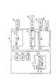
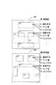
図1は、本発明の一実施形態にかかる画像処理装置を具体的に実現するコンピュータの構成を示している。同図において、コンピュータ10はCPU11とRAM12とROM13とハードディスクドライブ(HDD)14と汎用インターフェイス(GIF)15とビデオインターフェイス(VIF)16と入力インターフェイス(IIF)17とバス18とから構成されている。バス18は、コンピュータ10を構成する各要素11〜17の間でのデータ通信を実現するものであり、図示しないチップセット等によって通信が制御されている。HDD14には、オペレーティングシステム(OS)を含む各種プログラムを実行するためのプログラムデータ14aが記憶されており、当該プログラムデータ14aをRAM12に展開しながらCPU11が当該プログラムデータ14aに準じた演算を実行する。1. Configuration of Image Processing Device FIG. 1 shows the configuration of a computer that specifically implements an image processing device according to an embodiment of the present invention. In FIG. 1, a
また、HDD14には、デジタルスチルカメラやスキャナによって画像入力された画像データ14bが記憶されている。GIF15は、例えばUSB規格に準じたインターフェイスを提供するものであり、外部のプリンタ20をコンピュータ10に接続させている。VIF16はコンピュータ10を外部のディスプレイ40に接続し、ディスプレイ40に画像を表示するためのインターフェイスを提供する。IIF17はコンピュータ10を外部のキーボード50aとマウス50bに接続し、キーボード50aとマウス50bからの入力信号をコンピュータ10が取得するためのインターフェイスを提供する。 Further, the
図2は、コンピュータ10において実行されるプログラムのソフトウェア構成を示している。同図において、オペレーティングシステム(OS)PG1と画像処理アプリケーションPG2とプリンタドライバPG3が実行されている。OS PG1は各プログラム間のインターフェイスを提供し、プリンタドライバPG3はプリンタ20を制御するための処理を実行する。画像処理アプリケーションPG2は、作業画像取得部PG2aと検出窓設定部PG2bと窓画像取得部PG2cと第1特徴量算出部PG2d1と第2特徴量算出部PG2d2と第1顔判定部PG2e1と第2顔判定部PG2e2と画質調整部PG2fとから構成されている。画像処理アプリケーションPG2を構成する各モジュールPG2a〜PG2fが実行する処理の詳細については後述する画像処理の流れとともに説明する。 FIG. 2 shows a software configuration of a program executed in the
2.画像処理
図3は、画像処理の全体の流れを示している。同図において、画像処理は第1顔検出処理(ステップS100)と、絞り込み処理(ステップS200)と、第2顔検出処理(ステップS300)と、肌色補正処理(ステップS500)と印刷処理とから構成されている。また、第1顔検出処理(ステップS100)と第2顔検出処理(ステップS300)においてそれぞれ後述する検出窓SWが設定されるごとに、第1顔判定処理(ステップS600)と第2顔判定処理(ステップS700)が実行され、それぞれ検出窓SWに顔画像が存在するか否かの判定結果を出力する構成となっている。2. Image Processing FIG. 3 shows the overall flow of image processing. In the figure, the image processing includes a first face detection process (step S100), a narrowing process (step S200), a second face detection process (step S300), a skin color correction process (step S500), and a printing process. Has been. Each time a detection window SW described later is set in the first face detection process (step S100) and the second face detection process (step S300), the first face determination process (step S600) and the second face determination process are performed. (Step S700) is executed, and a determination result as to whether or not a face image exists in each detection window SW is output.
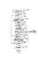
2−1.第1顔検出処理
図4は、第1顔検出処理の流れを示し、図5は作業画像データWDを示している。ステップS110では、作業画像取得部PG2aが所定のUI画面をディスプレイ40に表示させるとともに、キーボード50aとマウス50bから操作を受け付ける。それにより、HDD14等に記憶された複数の画像データ14bのなかからユーザーが印刷したい画像データ14bを取得する。作業画像取得部PG2aが画像データ14bの解像度を変換することにより、320画素×240画素(QVGA)の作業画像データWDを生成する。2-1. First Face Detection Process FIG. 4 shows the flow of the first face detection process, and FIG. 5 shows the work image data WD. In step S110, the work image acquisition unit PG2a displays a predetermined UI screen on the
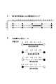
図5において、作業画像データWDに正方形状領域の検出窓(検出領域)SWが設定されており、第1顔検出処理おいては検出窓設定部PG2bが検出窓SWを作業画像データWDにおいて隈無く移動させていく。なお、作業画像データWDの長手方向をx軸とし、短手方向をy軸と表すものとし、x軸とy軸の原点は作業画像データWDの左上隅位置とする。ステップS120においては、検出窓設定部PG2bが検出窓SWの中心位置Pを指定するための方向カウンタnx,nyをリセットする。各方向カウンタnx,nyは、整数値であり、リセットによって0とされる。ステップS130においては、y方向カウンタnyに1を加算する。同様にステップS140において、x方向カウンタnxに1を加算する。次のステップS150においては、検出窓設定部PG2bが検出窓SWの中心位置Pの座標を下記の(1)式に基づいて算出する。
上記の(1)式において、dx,dyは検出窓SWの中心位置Pの各方向への単位移動距離(画素数)を示す一定の移動間隔を表しており、移動間隔dx,dyと方向カウンタnx,nyをそれぞれ乗算することにより、検出窓SWの中心位置Pのx,y座標を算出する。移動間隔dx,dyは下記の(2)式によって定義されるものとする。
上記の(2)式において、検出窓SWの中心位置Pのy方向への移動間隔dyは検出窓SWのサイズSの4%とされている。上記の(2)式によって移動間隔dy<1となる場合は、dy=1とする。また、y方向カウンタnsの上限値は、上記の(1)式による検出窓SWの中心位置Pのy座標が作業画像データWDの内側に収まるように、240/(0.04×S)(整数部分)とされる。なお、本実施形態では単一のサイズSの検出窓SWを設定するものを例示して説明するが、実際にはサイズSを変化させながら顔検出を行っていく。一方、x方向への移動間隔dxは検出窓SWのサイズSの50%とされている。x方向カウンタnxの上限値は、320/(0.5×S)(整数部分)とされる。ステップS160においては、ステップS150においてそれぞれ算出した中心位置Pを中心としてサイズSの検出窓SWを生成するとともに、検出窓SWの一部が作業画像データWDの外側にはみ出ていないか否かを判定する。In FIG. 5, a square area detection window (detection area) SW is set in the work image data WD. In the first face detection process, the detection window setting unit PG2b sets the detection window SW in the work image data WD. I will move without. Note that the longitudinal direction of the work image data WD is represented as the x-axis, the short direction is represented as the y-axis, and the origins of the x-axis and y-axis are the upper left corner position of the work image data WD. In step S120, the detection window setting section PG2b resets the direction counter nx, the ny for specifying the center position P of the detection window SW. Each direction counternx ,ny is an integer value and is set to 0 by reset. In step S130, 1 is added to the y direction counter ny. Similarly, in step S140, 1 is added to the x direction counter nx. In the next step S150, the detection window setting unit PG2b calculates the coordinates of the center position P of the detection window SW based on the following equation (1).
In the above (1), dx, dy represents a certain movement distance showing a unit moving distance (number of pixels) in each direction of the center position P of the detection window SW, the movement distance dx, d by multiplyingy and direction counter nx, ny, respectively, x of the center position P of the detection window SW, calculates the y-coordinate. Movement distance dx, dy is to be defined by the following expression (2).
In the above (2), the moving distance dy in the y direction of the center position P of the detection window SW is 4% of the size S of the detection window SW. When the movement interval dy <1 by the above equation (2), dy = 1. The upper limit of y direction counter ns, like the y coordinate of the center position P of the detection window SW according to the above (1) fits inside the working image data WD, 240 / (0.04 × S ) (Integer part). In the present embodiment, an example in which a detection window SW having a single size S is set will be described. However, in actuality, face detection is performed while the size S is changed. On the other hand, the movement distance dx in the x direction is 50% of the size S of the detection window SW. upper limit of x direction counter nx is a 320 / (0.5 × S) (integer part). In step S160, a detection window SW of size S is generated around the center position P calculated in step S150, and it is determined whether a part of the detection window SW does not protrude outside the work image data WD. To do.
図6は、ステップS160における判定の様子を模式的に示している。同図に示すように、各方向カウンタnx,nyの変動によって検出窓SWの位置と大きさがシフトするため、ある各方向カウンタnx,nyの組み合わせにおいては検出窓SWの一部が作業画像データWDの外側にはみ出ることとなる。このような場合に正常な顔検出を行うことができないとして、当該各方向カウンタnx,nyで特定される検出窓SWについての第1顔判定処理をスキップさせる。FIG. 6 schematically illustrates the determination in step S160. As shown in the figure, a part of the direction counter nx, the position and size of the detection window SW by variations in ny is shifted, the direction counter nx is, ny detection window SW is in combination with Will protrude outside the work image data WD. As it is impossible to perform a normal face detection in such cases, the respective directions counter nx, to skip the first face determining process for the detection window SW specified by ny.
以上のようにして、ステップS160にてスキップされた場合を除いて、各方向カウンタnx,nyが設定できると検出窓SWの大きさと位置が検出窓設定部PG2bによって一意に特定されたこととなる。ステップS170においては、窓画像取得部PG2cが現在決定されている検出窓SWの内側の画像データを抽出し、当該画像データを窓画像データXDとして取得する。取得した窓画像データXDは、第1特徴量算出部PG2d1および第1顔判定部PG2e1に出力され、窓画像データXDについての第1顔判定処理をステップS600にて実行する。ステップS170において、検出窓設定部PG2bは第1顔判定処理によって得られた当該検出窓SWにおける顔画像の有無を取得する。なお、第1顔判定処理の詳細については後述する。As described above, with the exception of the case where skipped at step S160, the size and position of each direction counter nx, and ny can be set detection window SW is uniquely identified by the detection window setting section PG2b It becomes. In step S170, the window image acquisition unit PG2c extracts the image data inside the currently determined detection window SW, and acquires the image data as window image data XD. The acquired window image data XD is output to the first feature amount calculation unit PG2d1 and the first face determination unit PG2e1, and the first face determination process for the window image data XD is executed in step S600. In step S170, the detection window setting unit PG2b acquires the presence / absence of a face image in the detection window SW obtained by the first face determination process. Details of the first face determination process will be described later.
ステップS180においては、x方向カウンタnx=320/(0.5×S)(整数部分)であるか否かを判定する。すなわち、現在の検出窓SWのy方向の位置における左端から右端までひととおり検出窓SWを設定したか否かを判定する。x方向カウンタnx<320/(0.5×S)(整数部分)である場合には、ステップS140に戻り、x方向カウンタnxを加算する。これにより、x方向右側に移動間隔dxだけ進んだ中心位置Pに検出窓SWを設定することができる。In step S180, it is determined whether or notx -direction counter nx = 320 / (0.5 × S) (integer part). That is, it is determined whether or not the detection window SW has been set from the left end to the right end at the current position in the y direction of the detection window SW. If the x-direction counter nx <320 / (0.5 × S) (integer part), the process returns to step S140, and the x-direction counternx is added. Thereby, the detection window SW can be set at the center position P advanced by the movement interval dx to the right in the x direction.
x方向カウンタnx=320/(0.5×S)であるとき、作業画像データWDの右端付近に検出窓SWの中心位置Pが移動することとなり、当該y方向の位置における移動を終了させる。ステップS185においてはx方向カウンタnxを0にリセットさせ、ステップS190にてy方向カウンタny=240/(0.04×S)(整数部分)であるかを判定する。ここで、y方向カウンタny<240/(0.04×S)(整数部分)であれば、ステップS130に戻る。ステップS130ではy方向カウンタnyに1を加算し、再度、ステップS140〜ステップS180を繰り返して実行する。これにより、一段進んだy方向に位置において検出窓SWの中心位置Pをx方向に移動させていくことができる。When the x direction counter nx = 320 / (0.5 × S), the center position P of the detection window SW moves near the right end of the work image data WD, and the movement at the position in the y direction is terminated. . Resets the x direction counter nx to 0 in step S185, determines whether the y direction counter ny = 240 / step S190 (0.04 × S) (integer part). Here, if the y-direction counter ny <240 / (0.04 × S) (integer part), the process returns to step S130. Step S130 adds 1 to the y direction counter ny In again repeatedly executes steps S140~ step S180. As a result, the center position P of the detection window SW can be moved in the x direction at a position in the y direction that is advanced by one step.
図7は、以上の処理を実行することにより、順次移動していく検出窓SWの様子を示している。上記の(1)式によって検出窓SWの中心位置Pを決定しているため、作業画像データWDにおいて検出窓SWの中心位置Pは、x方向に移動間隔dxの周期で分布し、y方向に移動間隔dyの周期で分布する格子点上に移動していくこととなる。最終的に、y方向カウンタny=240/(0.04×S)(整数部分)となったとき、作業画像データWDの最下端まで検出窓SWの中心位置Pを設定することができたとして、第1顔検出処理を終了させる。FIG. 7 shows a state of the detection window SW that sequentially moves by executing the above processing. Since the center position P of the detection window SW is determined by the above equation (1), the center position P of the detection window SW in the work image data WD is distributed in the x direction with a period of the movement interval dx and is in the y direction. so that the moves on the grid points distributed in a cycle of movement distance dy in. Finally, when the y-direction counter ny = 240 / (0.04 × S) (integer part), the center position P of the detection window SW could be set up to the lowest end of the work image data WD. Then, the first face detection process is terminated.
2−2.絞り込み処理:
図8は、検出窓設定部PG2bが第1顔検出処理の後に実行させる絞り込み処理の流れを示している。上述した第1顔検出処理のステップS170において検出窓設定部PG2bが窓画像データXDを出力するごとに、第1顔判定処理が実行され、その判定結果が検出窓SWの位置情報とともにWRAM12やHDD14に記憶されている。ステップS210においては、各中心位置Pの検出窓SWについて行われた第1顔判定処理による顔画像の有無の判定結果を作業画像データWDにおいてマッピングする。2-2. Narrowing process:
FIG. 8 shows the flow of the narrowing-down process that the detection window setting unit PG2b executes after the first face detection process. Each time the detection window setting unit PG2b outputs the window image data XD in step S170 of the first face detection process described above, the first face determination process is executed, and the determination result together with the position information of the detection window SW and the
図9Aは、y方向のある位置(y=10)について第1顔判定処理による顔画像の有無の判定結果をマッピングした様子を示している。同図において、第1顔判定処理によって顔画像が存在すると判定された検出窓SWの中心位置Pを○でプロットし、第1顔判定処理によって顔画像が存在しないと判定された検出窓SWの中心位置Pを●でプロットしている。以下、第1顔判定処理によって顔画像が存在すると判定された検出窓SWの中心位置Pを存在位置と表記し、第1顔判定処理によって顔画像が存在しないと判定された検出窓SWの中心位置Pを不存在位置と表記する。なお、移動間隔dx,dyをそれぞれ5画素,1画素としたときの例を示しており、○と●でプロットされた存在位置と不存在位置との間には4画素分の位置が存在している。ステップS220においては、存在位置同士がx方向において隣接している区間(○と○が隣接する区間)を検出し、当該区間を検出対象区間(太線で図示。)とする。さらに、不存在位置同士がx方向において隣接している区間(●と●が隣接する区間)を検出し、当該区間を検出対象外区間(破線で図示。)とする。また、存在位置と、不存在位置がx方向において隣接している区間(○と●が隣接する区間)を検出し、当該区間を未確定区間(細線で図示。)とする。FIG. 9A shows a state in which the determination result of the presence or absence of a face image by the first face determination process is mapped at a position in the y direction (y = 10). In the same figure, the center position P of the detection window SW determined that the face image exists by the first face determination process is plotted with ◯, and the detection window SW determined that the face image does not exist by the first face determination process. The center position P is plotted with ●. Hereinafter, the center position P of the detection window SW in which the face image is determined to be present by the first face determination process will be referred to as an existing position, and the center of the detection window SW in which the face image has been determined not to exist by the first face determination process will be described. The position P is expressed as a non-existing position. The movement distance dx, respectively 5 pixels dy, shows an example when the one pixel, the position of the four pixels between the present position and the absence position plotted by ○ and ● Existing. In step S220, a section in which the existing positions are adjacent in the x direction (a section in which ◯ and ◯ are adjacent) is detected, and the section is set as a detection target section (shown by a bold line). Further, a section in which the non-existing positions are adjacent in the x direction (a section in which ● and ● are adjacent) is detected, and the section is set as a non-detection section (illustrated by a broken line). Further, a section in which the presence position and the non-existence position are adjacent in the x direction (a section in which ◯ and ● are adjacent) is detected, and the section is set as an undetermined section (illustrated by a thin line).
ステップS230においては、以上のようにして定義された各区間内の各位置(画素)についてそれぞれ異なる規則を適用して移動順序を設定する。図9Aにおいては、ステップS230にて設定される移動順序が示されている。基本的には、作業画像データWDの左上端の画素の移動順序を1とし、x方向右側に1画素進むに連れて1ずつ移動順序が大きくなっていく。そして、右端の画素まで移動順序が設定できると、一段下の画素について同様に右端から左端に向かって昇順となるように移動順序を設定することを繰り返すことにより、すべての画素に移動順序を設定する。そのため、図9Bに示すように、検出対象外区間(破線で図示。)と検出対象外区間(破線で図示。)においては左端の画素の移動順序をuとすると、右に1画素ずつずれるにつれて順序が1ずつ加算されていく。しかし、未確定区間(細線で図示。)においては、顔画像が存在すると判定された存在位置(○で図示)から顔画像が存在しないと判定された不存在位置(●で図示)に向かう方向(○から●に向かう方向)に昇順となるように各画素の移動順序を設定する。従って、図9Bの最下段に図示するように、不存在位置(●で図示)が左端に位置し、存在位置(○で図示)が右端に位置する未確定区間(細線で図示。)においては、左に1画素ずつずれるにつれて順序が1ずつ加算されていくこととなる。 In step S230, the movement order is set by applying different rules to each position (pixel) in each section defined as described above. FIG. 9A shows the movement order set in step S230. Basically, the order of movement of the upper left pixel of the work image data WD is 1, and the order of movement increases by 1 as the pixel advances to the right in the x direction. Once the movement order can be set up to the rightmost pixel, the movement order is set for all the pixels by repeating the setting of the movement order so that the lowermost pixel is in ascending order from the right edge toward the left edge. To do. Therefore, as shown in FIG. 9B, in the non-detection interval (illustrated by a broken line) and the non-detection interval (illustrated by a broken line), assuming that the movement order of the leftmost pixel is u, the pixel is shifted to the right by one pixel. The order is incremented by one. However, in an undetermined section (illustrated by a thin line), a direction from an existing position where a face image is determined to be present (illustrated by a circle) to a non-existing position where a face image is determined not to be present (illustrated by a circle). The movement order of each pixel is set so as to be in ascending order (in the direction from ○ to ●). Therefore, as shown in the lowermost stage of FIG. 9B, in the unconfirmed section (shown by a thin line) where the nonexisting position (shown by ●) is located at the left end and the existing position (shown by ○) is located at the right end. The order is incremented by 1 as the pixel is shifted to the left.
また、ステップS240では、検出対象区間(太線で図示。)の各画素、および、顔画像が存在すると判定された存在位置と重複する画素については、検出フラグTfを添付する。一方、検出対象外区間(破線で図示。)の各画素、および、顔画像が存在しないと判定された不存在位置(●で図示)と重複する画素については、非検出フラグFfを添付する。さらに、未確定区間(細線で図示。)の各画素については、未確定フラグNfを添付する。ステップS250においては、以上のようにして設定した各画素の位置と移動順序と各フラグTf,Nf,Ffを格納した検出位置テーブルTBを生成し、RAM12やHDD14に記憶させる。 In step S240, a detection flag Tf is attached to each pixel in the detection target section (shown by a bold line) and a pixel that overlaps with an existing position where a face image is determined to exist. On the other hand, a non-detection flag Ff is attached to each pixel in a non-detection section (illustrated by a broken line) and a pixel overlapping with a non-existing position (illustrated by ●) where it is determined that a face image does not exist. Further, an undetermined flag Nf is attached to each pixel in the undetermined section (illustrated by a thin line). In step S250, a detection position table TB storing the positions and movement orders of the pixels set as described above and the flags Tf, Nf, and Ff is generated and stored in the
図10は、検出位置テーブルTBを示している。同図において、図9Aに示したy=11のマップに対応する部分が示されている。各移動順序の昇順に各画素の位置を示すxy座標が対応付けられて格納されているとともに、各画素について対応する区間のフラグTf,Nf,Ffが添付されている。y方向の位置が単一であれば、基本的に移動順序が後になればx方向の位置が右方向に進む関係となるが、9Bで示すように存在位置(○で図示)が右端に位置する未確定区間(細線で図示。)については移動順序が後になるとx方向の位置が左方向に戻ることとなる(図10において二重枠で図示した部分。)。このような検出位置テーブルTBによれば、後述する第2顔検出処理において、どのような順序でどの位置に検出窓SWの中心位置Pを設定すべきかを特定することができる。なお、検出位置テーブルTBに格納された移動順序の値は、後述する第2顔検出処理にて使用される位置カウンタnp(整数値)に対応している。検出位置テーブルTBが生成できると、ステップS300において第2顔検出処理を実行させる。FIG. 10 shows the detection position table TB. In the figure, a portion corresponding to the map of y = 11 shown in FIG. 9A is shown. The xy coordinates indicating the position of each pixel are stored in association with each other in ascending order of the movement order, and the corresponding section flags Tf, Nf, and Ff are attached to each pixel. If the position in the y direction is single, basically the position in the x direction advances to the right if the movement order is later, but the existence position (shown by ○) is located at the right end as shown by 9B. As for the unconfirmed section (illustrated by a thin line), the position in the x direction returns to the left when the moving order is later (the portion illustrated by the double frame in FIG. 10). According to such a detection position table TB, it is possible to specify in what order and at which position the center position P of the detection window SW should be set in the second face detection process described later. The value of the movement order stored in the detection position table TB corresponds to a position counter np (integer value) used in the second face detection process described later. When the detection position table TB can be generated, the second face detection process is executed in step S300.
2−3.第2顔検出処理:
図11は、第2顔検出処理の流れを示している。ステップS310において、検出窓設定部PG2bが位置カウンタnpを0にリセットする。ステップS320においては、位置カウンタnpに1を加算する。ステップS330においては、検出窓設定部PG2bが検出位置テーブルTBおよび作業画像データWDを取得する。ステップS340においては、検出位置テーブルTBを参照して位置カウンタnpに対応付けられた位置のxy座標を取得する。ステップS345においては、当該取得した位置に対して非検出フラグFfが添付されているか否かを判定する。非検出フラグFfが添付されている場合には、ステップS320に戻り、位置カウンタnpに1を加算する。2-3. Second face detection process:
FIG. 11 shows the flow of the second face detection process. In step S310, the detection window setting unit PG2b resets the position counter np to 0. In step S320, 1 is added to the position counter np . In step S330, the detection window setting unit PG2b acquires the detection position table TB and the work image data WD. In step S340, the xy coordinates of the position associated with the position counternp are acquired with reference to the detected position table TB. In step S345, it is determined whether or not a non-detection flag Ff is attached to the acquired position. If the non-detection flag Ff is attached, the process returns to step S320, and 1 is added to the position counternp .
一方、ステップS340において取得した位置に対して検出フラグTfと未確定フラグNfが添付されている場合には、ステップS350にて、当該位置のxy座標を中心位置Pとする検出窓SWを検出窓設定部PG2bが設定する。ステップS360においては、窓画像取得部PG2cが現在設定されている検出窓SWの内側の窓画像データXDを取得する。取得した窓画像データXDは、第2特徴量算出部PG2d2および第2顔判定部PG2e2に出力され、窓画像データXDについての第2顔判定処理をステップS700にて実行する。ステップS700において顔画像が存在すると判定された場合、そのときの検出窓SWの位置をRAM12に記憶させる。なお、第2顔判定処理の詳細については後述する。 On the other hand, when the detection flag Tf and the unconfirmed flag Nf are attached to the position acquired in step S340, in step S350, the detection window SW having the xy coordinate of the position as the center position P is set as the detection window. Set by the setting unit PG2b. In step S360, the window image acquisition unit PG2c acquires window image data XD inside the currently set detection window SW. The acquired window image data XD is output to the second feature amount calculation unit PG2d2 and the second face determination unit PG2e2, and the second face determination process for the window image data XD is executed in step S700. If it is determined in step S700 that a face image exists, the position of the detection window SW at that time is stored in the
ステップS370において、現在の検出窓SWの位置に未確定フラグNfが添付されており、かつ、第2顔判定処理(ステップS700)にて現在の検出窓SWの窓画像データXDに顔画像が存在しないと判定されたかを判断する。そして、現在の検出窓SWの位置に未確定フラグNfが添付されており、かつ、第2顔判定処理(ステップS700)にて現在の検出窓SWの窓画像データXDに顔画像が存在しないと判定された場合には、検出位置テーブルTBにおいて、現在の位置の移動順序の直後(図11の検出位置テーブルTBにおける直下)に連続(単一の場合も含む)して存在する未確定フラグNfが添付された位置について、未確定フラグNfを非検出フラグFfに更新する(ステップS380)。ステップS390においては、位置カウンタnpが検出位置テーブルTBに記述された最終の移動順序に対応するものであるか否かを判定する。位置カウンタnpが最終のものでない場合には、ステップS320に戻り、位置カウンタnpを加算する。このようにすることにより、位置カウンタnpが最終のものとなるまで、順次検出窓SWの中心位置Pを移動させていくことができる。In step S370, the indeterminate flag Nf is attached to the current position of the detection window SW, and a face image exists in the window image data XD of the current detection window SW in the second face determination process (step S700). Judge whether it was decided not to do. Then, if the unconfirmed flag Nf is attached to the current position of the detection window SW, and the face image does not exist in the window image data XD of the current detection window SW in the second face determination process (step S700). If it is determined, an unconfirmed flag Nf that is continuously (including a single case) immediately after the moving order of the current position (immediately below the detection position table TB in FIG. 11) in the detection position table TB. The unconfirmed flag Nf is updated to the non-detection flag Ff for the position where is attached (step S380). In step S390, it is determined whether or not the position counter np corresponds to the final movement order described in the detected position table TB. If the position counter np is not the final one, the process returns to step S320, and the position counter np is added. By doing in this way, the center position P of the detection window SW can be sequentially moved until the position counter np becomes the final one.
図12Bは以上の第2顔検出処理において移動する検出窓SWの様子を、第1顔検出処理(ステップS100)における第1顔判定処理(ステップS600)による判定結果(12A)と対比して示している。同図おいては、図9Aに示したy=11のマップに対応する部分について検出窓SWが移動する様子を示している。ここで、第1顔判定処理によって顔画像が存在しないと不存在位置(●で図示)、および、当該不存在位置同士の間の検出対象外区間(破線で図示。)の位置について非検出フラグFfが添付されているため、これらの位置については第2顔判定処理(ステップS700)がスキップされることとなる。なお、スキップされた位置は−で図示し、第2顔判定処理が実行された位置は◎で図示する。一方、第1顔判定処理によって顔画像が存在すると判定された存在位置(○で図示)および、当該存在位置同士の間の検出対象区間(太線で図示。)の位置について検出フラグTfが添付されているため、当該位置については検出窓SWの中心位置Pが各画素について設定され、第2顔判定処理(ステップS700)が実行されることとなる。 FIG. 12B shows the state of the detection window SW that moves in the second face detection process described above in comparison with the determination result (12A) by the first face determination process (step S600) in the first face detection process (step S100). ing. In the same figure, it is shown that the detection window SW moves for a portion corresponding to the map of y = 11 shown in FIG. 9A. Here, if a face image does not exist in the first face determination process, a non-detection flag is set for a non-existing position (indicated by ●) and a position in a non-detection section (indicated by a broken line) between the non-existing positions. Since Ff is attached, the second face determination process (step S700) is skipped for these positions. Note that the skipped position is indicated by-, and the position where the second face determination process is executed is indicated by ◎. On the other hand, a detection flag Tf is attached for the position of the presence position (indicated by a circle) determined that the face image is present by the first face determination processing and the position of the detection target section (indicated by the bold line) between the existence positions. For this position, the center position P of the detection window SW is set for each pixel, and the second face determination process (step S700) is executed.
第1顔判定処理(ステップS600)において顔画像が存在すると判定された存在位置と、顔画像が存在しないと判定された不存在位置との間の未確定区間(細線で図示。)においては、存在位置から不存在位置に向かう方向(○から●に向かう方向)に昇順となるように移動順序が設定されている。そのため、未確定区間においては、存在位置から近い方の各位置を優先させて検出窓SWの中心位置Pが設定され、第2顔判定処理(ステップS700)を実行することができる。ただし、当該未確定区間のいずれかの位置について、第2顔判定処理にて顔画像が存在しないと判定された段階で、当該未確定区間の未処理の各位置についての未確定フラグNfを非検出フラグFfに更新するため、それ以降の未確定区間の位置については第2顔判定処理を実行させなくすることができる。図12Cにおいては、第2顔判定処理による判定結果を示しており、未確定区間にて顔画像が存在しないと第2顔判定処理によって判定された位置(●で図示)よりも後の移動順序とされた位置については、図12Bに示すようにスキップされている。すなわち、第1顔判定処理において顔画像が存在すると判定された存在位置から近い位置の順に第2顔判定処理を実行させるが、第2顔判定処理にて顔が検出されなかった位置よりも、存在位置から遠くにある位置については、第2顔判定処理を実行させないようにしている。 In an undetermined section (shown by a thin line) between the presence position where it is determined that the face image exists in the first face determination process (step S600) and the non-existence position where it is determined that the face image does not exist. The movement order is set so as to be in ascending order in the direction from the existing position to the non-existing position (direction from ○ to ●). Therefore, in the unconfirmed section, the center position P of the detection window SW is set by giving priority to each position closer to the existing position, and the second face determination process (step S700) can be executed. However, the unconfirmed flag Nf for each unprocessed position in the unconfirmed section is set to the non-confirmed flag Nf at the stage where it is determined in the second face determination process that no face image exists for any position in the unconfirmed section. Since the detection flag Ff is updated, the second face determination process can be prevented from being executed for the position of the unconfirmed section thereafter. FIG. 12C shows the determination result by the second face determination process, and the movement order after the position (shown by ●) determined by the second face determination process when no face image exists in the undetermined section. As shown in FIG. 12B, these positions are skipped. That is, the second face determination process is executed in the order of the position closer to the presence position where the face image is determined to be present in the first face determination process, but than the position where the face was not detected in the second face determination process, The second face determination process is not executed for a position far from the existing position.
第1顔判定処理(ステップS600)によって顔画像が存在しないと判定された不存在位置同士の検出対象外区間においては、それ以上、第2顔判定処理(ステップS700)を実行しても顔が検出される可能性は低いと考えることができる。従って、検出対象外区間について第2顔判定処理を実行させないことにより、無駄な処理を防止することができる。これに対して、第1顔判定処理によって顔画像が存在すると判定された存在位置同士の検出対象区間においては、第2顔判定処理において顔が検出される可能性が高いと考えることができる。従って、検出対象区間のすべての位置について第2顔判定処理を実行させることによろい、漏れのない顔検出を実現することができる。 In the non-detection section between the non-existing positions where the face image is determined not to exist by the first face determination process (step S600), the face is not detected even if the second face determination process (step S700) is further executed. It can be considered that the possibility of being detected is low. Therefore, useless processing can be prevented by not executing the second face determination processing for the non-detection target section. On the other hand, it can be considered that in the detection target section between the existing positions where the face image is determined to exist by the first face determination process, the possibility that the face is detected in the second face determination process is high. Therefore, the face detection without omission can be realized by executing the second face determination process for all the positions in the detection target section.
さらに、第1顔判定処理によって顔画像が存在すると判定された存在位置と顔画像が存在しないと判定された不存在位置との間の未確定区間においては、存在位置に近いほど第2顔判定処理において顔が検出される可能性が高いということができる。従って、存在位置に近い位置から先に第2顔判定処理を実行させることにより、早期に顔を検出することができる。さらに、未確定区間について第2顔判定処理を実行させた結果、顔画像が存在しないと判定された位置よりも、第1顔判定処理によって顔画像が存在すると判定された存在位置から遠い位置については、顔画像が存在する可能性が低いと考えることができる。従って、このような位置について第2顔判定処理を実行させないことにより、無駄な処理を防止することができる。 Furthermore, in an unconfirmed section between the presence position determined by the first face determination processing that the face image is present and the non-existence position determined that the face image does not exist, the second face determination becomes closer to the presence position. It can be said that the possibility that a face is detected in the processing is high. Therefore, the face can be detected at an early stage by executing the second face determination process first from a position close to the presence position. Further, as a result of executing the second face determination process for the unconfirmed section, a position farther from the position where the face image is determined to be present by the first face determination process than the position where it is determined that the face image does not exist. Can be considered to be unlikely to have a face image. Therefore, useless processing can be prevented by not executing the second face determination processing for such a position.
ステップS390において、位置カウンタnpが最終のものであると判定された場合には、ステップS395において第2顔判定処理(ステップS700)によってRAM12に記憶された各位置についての判定結果のマップを取得する。そして、第2顔判定処理による判定結果のマップに基づいて最終的な顔検出の結果を出力する。図12Cに示すように、検出対象外区間および未確定区間の一部については、検出窓SWの中心位置Pの設定がスキップされているため、第2顔判定処理(ステップS700)の判定結果が得られていない(−で図示。)。一方、検出対象区間および未確定区間の一部については、各画素について第2顔判定処理による顔画像が存在する(○で図示。)か、存在しない(●で図示。)かの判定結果が各画素について得られている。If it is determined in step S390 that the position counter np is the last one, a determination result map for each position stored in the
ここで、検出窓SWのサイズSよりも狭い範囲において顔画像が存在すると判定された画素が連続する場合、複数の顔画像が存在しているのではなく、単一の顔画像が複数の隣接位置において検出されたものと考えられる。従って、このような場合には、顔画像が存在すると判定された隣接画素の中央の画素の位置を顔画像が存在する位置であるとしたり、顔画像が存在すると判定された隣接画素のうち最も第2顔判定処理において高い評価であった画素(後述するニューラルネットワークNN2の出力値が大きかったもの)画素の位置を顔画像が存在する位置であるとする。なお、第1顔判定処理において存在位置と判定されたにもかかわらず、第2顔判定処理において顔画像が存在しないと判定される場合も考えられる。このような場合には、第2顔判定処理の方が位置に関する精度が高いため、第2顔判定処理の結果を優先するものとする。以上によって、作業画像データWDにおいて顔画像が存在する位置が最終的に特定できたこととなり、当該位置についての情報をRAM12に記憶させて処理を終了させる。 Here, when pixels determined to have a face image in a range narrower than the size S of the detection window SW are continuous, a single face image is not a plurality of face images but a plurality of adjacent face images are present. It is thought that it was detected at the position. Therefore, in such a case, the position of the center pixel of the adjacent pixels determined to have the face image is assumed to be the position where the face image exists, or the most adjacent pixels determined to have the face image exist. It is assumed that the position of a pixel that is highly evaluated in the second face determination process (the output value of a neural network NN2 described later) is a position where the face image exists. There may be a case where it is determined that the face image does not exist in the second face determination process even though it is determined in the first face determination process. In such a case, the second face determination process has higher accuracy with respect to the position, so the result of the second face determination process is given priority. As a result, the position where the face image exists in the work image data WD has been finally identified. Information about the position is stored in the
2−4.顔判定処理
図13は、第1顔判定処理と第2顔判定処理の流れを示している。なお、第1顔判定処理と第2顔判定処理の実行に必要なプログラムコードをCPU11が読み込むことにより、本発明の第1判定手段と第2判定手段とが用意されることとなる。同図に示すように第1顔判定処理と第2顔判定処理は同様の処理とされている。ステップS610,S620にて窓画像データXDを取得すると、次のステップS620,S720において第1特徴量算出部PG2d1と第2特徴量算出部PG2d2がそれぞれステップS170,S360にて取得した窓画像データXDから複数の特徴量を算出する。これらの特徴量は、窓画像データXDに対して各種のフィルタを適用し、当該フィルタ内の輝度平均やエッジ量やコントラスト等の画像的特徴を示す特徴量(平均値や最大値や最小値や標準偏差等)を算出することにより得られる。2-4. Face Determination Process FIG. 13 shows the flow of the first face determination process and the second face determination process. The
図14は、窓画像データXDから特徴量を算出する様子を示している。同図において、窓画像データXDに対して多数のフィルタFTが用意されており、各フィルタFTを順次窓画像データXDに適用し、各フィルタFT内の画像的特徴に基づいて、複数の特徴量CA,CA,CA…を算出する。第1特徴量算出部PG2d1と第2特徴量算出部PG2d2が算出する特徴量CA,CA,CA…は互いに異なっており、第1特徴量算出部PG2d1よりも第2特徴量算出部PG2d2によって算出される特徴量CA,CA,CA…の数の方が多くされている。特徴量CA,CA,CA…が算出できると、ステップS630,730において、第1顔判定部PG2e1と第2顔判定部PG2e2がそれぞれ特徴量CA,CA,CA…を予め用意されたニューラルネットワークNNに入力し、その出力として顔画像が存在する/しないの判定結果を算出する。 FIG. 14 shows how the feature amount is calculated from the window image data XD. In the figure, a large number of filters FT are prepared for the window image data XD. Each filter FT is sequentially applied to the window image data XD, and a plurality of feature amounts are obtained based on the image characteristics in each filter FT. CA, CA, CA... Are calculated. The feature amounts CA, CA, CA... Calculated by the first feature amount calculation unit PG2d1 and the second feature amount calculation unit PG2d2 are different from each other, and are calculated by the second feature amount calculation unit PG2d2 rather than the first feature amount calculation unit PG2d1. The number of feature amounts CA, CA, CA. When the feature amounts CA, CA, CA... Can be calculated, in steps S630 and 730, the first face determination unit PG2e1 and the second face determination unit PG2e2 respectively provide the feature amounts CA, CA, CA. And a determination result of whether or not a face image exists is calculated as the output.
図15は、第1顔判定部PG2e1と第2顔判定部PG2e2がそれぞれ使用するニューラルネットワークNN1,NN2の構造の一例を対比して示している。ニューラルネットワークNN1,NN2は、前段層のユニットUの値の線形結合(添え字iは前段層のユニットUの識別番号。)によって後段層のユニットUの値が決定される基本構造を有している。さらに、線形結合によって得られた値をそのまま次の層のユニットUの値としてもよいが、線形結合によって得られた値を例えばハイパボリックタンジェント関数のような非線形関数によって変換して次の層のユニットUの値を決定することにより、非線形特性を与えてもよい。第1顔判定部PG2e1が使用するニューラルネットワークNN1は3層構造となっており、第2顔判定部PG2e2が使用するニューラルネットワークNN2は4層構造となっている。ニューラルネットワークNN1,NN2は、最外の入力層と出力層と、これらに挟まれた中間層から構成されている。各特徴量CA,CA,CA…がニューラルネットワークNNの入力層に入力可能となっており、出力層では出力値K(0〜1に正規化された値)を出力することが可能となっている。なお、第1特徴量算出部PG2d1よりも第2特徴量算出部PG2d2によって算出される特徴量CA,CA,CA…の数の方が多いため、第2顔判定部PG2e2が使用するニューラルネットワークNN2の方が入力層を構成するユニットUの数が多く複雑な構造となっている。 FIG. 15 shows an example of the structure of the neural networks NN1 and NN2 used by the first face determination unit PG2e1 and the second face determination unit PG2e2, respectively. The neural networks NN1 and NN2 have a basic structure in which the value of the unit U in the subsequent layer is determined by a linear combination of the values of the unit U in the previous layer (subscript i is the identification number of the unit U in the previous layer). Yes. Further, the value obtained by the linear combination may be used as the value of the unit U of the next layer as it is, but the value obtained by the linear combination is converted by a non-linear function such as a hyperbolic tangent function, for example. By determining the value of U, non-linear characteristics may be provided. The neural network NN1 used by the first face determination unit PG2e1 has a three-layer structure, and the neural network NN2 used by the second face determination unit PG2e2 has a four-layer structure. The neural networks NN1 and NN2 are composed of an outermost input layer and output layer, and an intermediate layer sandwiched between them. Each feature quantity CA, CA, CA... Can be input to the input layer of the neural network NN, and an output value K (value normalized to 0 to 1) can be output from the output layer. Yes. Note that the number of feature amounts CA, CA, CA... Calculated by the second feature amount calculation unit PG2d2 is larger than that of the first feature amount calculation unit PG2d1, and thus the neural network NN2 used by the second face determination unit PG2e2. In this case, the number of units U constituting the input layer is large and the structure is complicated.
第1顔判定部PG2e1と第2顔判定部PG2e2は、それぞれニューラルネットワークNN1,NN2の出力値Kが0.5以上であれば窓画像データXDに顔画像が存在すると判定し、出力値Kが0.5未満であれば窓画像データXDに顔画像が存在しないと判定する(ステップS640,S740)。このようなニューラルネットワークNN1,NN2をHDD14に予め用意しておけば、顔画像が窓画像データXDに存在するか否かを特徴量CA,CA,CA…に基づいて判定することができる。 The first face determination unit PG2e1 and the second face determination unit PG2e2 determine that a face image exists in the window image data XD if the output value K of the neural networks NN1 and NN2 is 0.5 or more, respectively, and the output value K is If it is less than 0.5, it is determined that no face image exists in the window image data XD (steps S640 and S740). If such neural networks NN1 and NN2 are prepared in advance in the
図16は、ニューラルネットワークNN1,NN2を学習する様子を模式的に示している。なお、学習方法は同様であるためニューラルネットワークNN1のみ図示するものとする。本実施形態では、誤差逆伝搬(error back propagation)法によって学習を行うことにより、各ユニットUの数や、各ユニットU間における線形結合の際の重みwの大きさやバイアスbの値が最適化される。ニューラルネットワークNN2の方が構造が複雑であるため、最適化すべき重みwの大きさやバイアスbの数も多くなる。誤差逆伝搬法による学習においては、まず各ユニットU間における線形結合の際の重みwの大きさやバイアスbの値を適当な値に初期設定する。そして、顔画像が存在しているか否かが既知の学習用画像データについてステップS620,S720と同様の手順で特徴量CA,CA,CA…を算出し、当該特徴量CA,CA,CA…を初期設定されたニューラルネットワークNN1,NN2に入力し、その出力値Kを取得する。 FIG. 16 schematically shows how the neural networks NN1 and NN2 are learned. Since the learning method is the same, only the neural network NN1 is illustrated. In the present embodiment, learning is performed by the error back propagation method, so that the number of units U, the size of weight w and the value of bias b at the time of linear combination between units U are optimized. Is done. Since the neural network NN2 has a more complicated structure, the size of the weight w to be optimized and the number of biases b are also increased. In learning by the back propagation method, first, the magnitude of the weight w and the value of the bias b at the time of linear combination between the units U are initially set to appropriate values. Then, feature amounts CA, CA, CA... Are calculated for the learning image data for which it is known whether or not a face image exists, in the same procedure as steps S620 and S720, and the feature amounts CA, CA, CA. Input to the initially set neural networks NN1 and NN2 to obtain the output value K.
本実施例において、顔画像が存在している学習用画像データについて出力値Kとして1が出力されるのが望ましく、顔画像が存在していない学習用画像データについて出力値Kとして0が出力されるのが望ましい。しかしながら、各ユニットU間における線形結合の際の重みwの大きさやバイアスbの値を適当な値に初期設定したに過ぎないため、実際の出力値Kと理想的な値との間には誤差が生じることとなる。このような誤差を極小化させる各ユニットUについての重みwやバイアスbを、勾配法等の数値最適化手法を用いて算出する。以上のような誤差は、後段の層から前段の層に伝搬され、後段のユニットUについて重みwやバイアスbから順に最適化されていく。 In this embodiment, it is desirable that 1 is output as the output value K for learning image data in which a face image exists, and 0 is output as the output value K for learning image data in which no face image exists. Is desirable. However, since the weight w and the value of the bias b at the time of linear combination between the units U are merely set to appropriate values, there is an error between the actual output value K and the ideal value. Will occur. The weight w and the bias b for each unit U that minimizes such an error are calculated using a numerical optimization method such as a gradient method. The errors as described above are propagated from the subsequent layer to the previous layer, and are optimized in order from the weight w and the bias b for the subsequent unit U.
図17は、ニューラルネットワークNN1,NN2のそれぞれの学習において使用される学習用画像データを対比して示している。学習用画像データは、多数用意されており、多種多様な顔をそれぞれ1ずつ含んでいる。ニューラルネットワークNN2の学習に使用される学習用画像データは顔の中心位置が学習用画像データの左右中央に厳密に一致するように作成されている。一方、ニューラルネットワークNN1の学習に使用される学習用画像データは顔の中心位置が学習用画像データの左右中央から多少ずれたものも含むように作成されている。すなわち、ニューラルネットワークNN1,NN2の学習に使用される学習用画像データに含まれる顔の中心位置の標準偏差は、ニューラルネットワークNN1の方が大きくなるようにされている。以上のようにして学習したニューラルネットワークNNによれば、窓画像データXDに顔画像が存在している場合の特徴量CA,CA,CA…に対して1に近い出力値Kを得ることができ、窓画像データXDに顔画像が存在していない場合の特徴量CA,CA,CA…に対して0に近い出力値Kを得ることができる。従って、適当な閾値0.5によって閾値判定を行うことにより、窓画像データXDに顔画像が存在しているか否かを判定することができる(ステップS640,S740)。 FIG. 17 shows learning image data used in learning of each of the neural networks NN1 and NN2. A large number of image data for learning is prepared and includes one each of a variety of faces. The learning image data used for learning of the neural network NN2 is created so that the center position of the face exactly matches the left and right center of the learning image data. On the other hand, the learning image data used for the learning of the neural network NN1 is created so that the center position of the face is slightly shifted from the left and right center of the learning image data. That is, the standard deviation of the center position of the face included in the learning image data used for learning of the neural networks NN1 and NN2 is made larger in the neural network NN1. According to the neural network NN learned as described above, an output value K close to 1 can be obtained for the feature quantities CA, CA, CA... When a face image exists in the window image data XD. The output value K close to 0 can be obtained for the feature amounts CA, CA, CA... When the face image does not exist in the window image data XD. Therefore, it is possible to determine whether or not a face image exists in the window image data XD by performing threshold determination with an appropriate threshold 0.5 (steps S640 and S740).
ステップS640,S740において窓画像データXDについて顔画像が存在すると判定された場合、そのときの窓画像データXDが得られた検出窓SWの中心位置をRAM12に記憶させ(ステップS650,S750)、リターンする。このようにしてRAM12に記憶された第1顔判定処理の判定結果に応じて前記絞り込み処理を実行することができるし、第2顔判定処理の判定結果に応じて後述する肌色調整および印刷処理を実行させることができる。一方、ステップS630,S730において窓画像データXDについて顔画像が存在しないと判定された場合、そのままリターンする。上述した第1顔検出処理と第2顔検出処理によって検出窓SWを移動させながら窓画像データXDが第1特徴量算出部PG2d1,第1特徴量算出部PG2d1に順次出力されるため、その度にステップS610〜S640,S710〜S740の処理を実行させる。これにより、順次移動される検出窓SWのそれぞれについて顔画像の存在の有無を判定していくことができる。 When it is determined in steps S640 and S740 that a face image exists for the window image data XD, the center position of the detection window SW from which the window image data XD at that time is obtained is stored in the RAM 12 (steps S650 and S750), and a return is performed. To do. In this way, the narrowing-down process can be executed according to the determination result of the first face determination process stored in the
学習画像データに含まれる顔の左右方向の位置にばらつきを持たせた第1顔判定処理の方が判定する顔が検出窓SWの中央から左右に多少ぶれていても顔画像が存在すると判定することができる。また、第1顔判定処理で使用するニューラルネットワークNN1の構造は簡易であり、算出すべき特徴量CA,CA,CA…の数も第2顔判定処理よりも少ないため、高速な判定を行うことができる。一方、学習画像データに含まれる顔の左右方向の位置のばらつきが小さい第2顔判定処理の方が高精度に顔画像の位置を特定することができる。すなわち、検出窓SWの左右中央に顔画像が存在する場合のみ顔画像が存在すると判定することとなるため、厳密に顔画像の位置を特定することができる。 It is determined that a face image exists even if the face to be determined by the first face determination process in which the positions of the faces included in the learning image data have variations in the left and right directions slightly deviate from the center of the detection window SW. be able to. Further, the structure of the neural network NN1 used in the first face determination process is simple, and the number of feature amounts CA, CA, CA... To be calculated is smaller than that in the second face determination process, so that high-speed determination is performed. Can do. On the other hand, the position of the face image can be specified with higher accuracy in the second face determination process in which the variation in the position in the left-right direction of the face included in the learning image data is smaller. That is, since it is determined that the face image exists only when the face image exists in the center of the left and right of the detection window SW, the position of the face image can be specified precisely.
作業画像データWDのすべての位置について第2顔判定処理を実行させれば、精度よい顔検出を実現させることができるが、第2顔判定処理による処理負担が膨大となる。そこで、図12にて説明したように、予め顔画像の左右のぶれに対するロバスト性に優れ、かつ、処理負担の少ない第1顔判定処理を作業画像データWDの全体わたる低密度の位置について実行させることにより、顔画像が存在しそうな領域を絞り込むことができる。そして、顔画像が存在しそうな領域についてのみ第2顔判定処理を実行させるため、第2顔判定処理を実行させる回数を低減することができ、処理効率を向上させることができる。第2顔判定処理は、高い位置精度を有するため、絞り込まれた領域において厳密に顔画像が存在する位置を最終的に特定することができる。第2顔判定処理は顔画像の左右のぶれに対するロバスト性が低いが、第2顔検出処理では絞り込まれた領域において細かく(高密度に)検出窓SWを移動させるため、顔画像が存在する位置を漏れなく特定することができる。 If the second face determination process is executed for all positions of the work image data WD, accurate face detection can be realized, but the processing load by the second face determination process becomes enormous. Therefore, as described with reference to FIG. 12, first face determination processing that is excellent in robustness against left and right blurring of the face image and that has a low processing load is executed on low-density positions throughout the entire work image data WD. Thus, it is possible to narrow down an area where a face image is likely to exist. Since the second face determination process is executed only for an area where a face image is likely to exist, the number of times the second face determination process is executed can be reduced, and the processing efficiency can be improved. Since the second face determination process has high position accuracy, it is possible to finally specify the position where the face image is strictly present in the narrowed down area. In the second face determination process, the robustness to the left and right blur of the face image is low, but in the second face detection process, the detection window SW is moved finely (with high density), so the position where the face image exists Can be identified without omission.
2−5.肌色補正処理および印刷処理:
図18は、画質調整部PG2eが実行する肌色補正処理の流れを示している。上述した第2顔検出処理の位置について検出窓SWの設定が完了したと判定すると、第2顔検出処理が終了するとともに、第2顔検出処理と同期して実行される第2顔判定処理も終了する。ステップS510においては、第2顔検出処理と第2顔判定処理の終了を検出し、調整対象の画像データ14bを取得する。ここで取得される画像データ14は、第1顔検出処理と第2顔検出処理の対象となった画像データ14bである。ステップS520においては、顔画像が存在すると判定された検出窓SWの位置と一定のサイズSをRAM12から読み出す。ステップS530においては、顔画像が存在すると判定された検出窓SWに対応する領域を画像データ14bにおいて特定する。検出窓SWの位置がRAM12から取得されているため、これを画像データ14bの画像サイズに換算することにより、検出窓SWに対応する領域を特定することができる。2-5. Skin color correction and printing:
FIG. 18 shows the flow of the skin color correction process executed by the image quality adjustment unit PG2e. When it is determined that the setting of the detection window SW has been completed for the position of the second face detection process described above, the second face detection process ends, and a second face determination process that is executed in synchronization with the second face detection process is also performed. finish. In step S510, the end of the second face detection process and the second face determination process is detected, and
ステップS540においては、ステップS530にて特定した領域に含まれる肌色画素の色をサンプリングし、当該色に基づいて画像データ14bに対する色調調整のためのパラメータを設定する。ここでは、まずステップS540にて特定した領域に含まれる肌色画素を、各画素の色彩値(例えばRGB値やHSV値)に基づいて特定し、当該色彩値を肌色として好ましいものに補正するための調整パラメータを算出する。調整パラメータは、例えばカラーバランスやホワイトバランスや明るさを調整するためのパラメータが該当する。予め肌色として好ましい色彩値がHDD14に記憶されており、各肌色画素の色彩値が好ましい色彩値に近づくような調整パラメータが算出される。検出窓SWによって顔画像が存在する領域が予め特定されているため、顔画像の肌色画素に基づいて調整パラメータを得ることができる。なお、顔画像が存在すると判定された検出窓SWが複数検出された場合には、平均的な調整パラメータの算出を実行する。調整パラメータが算出できると、ステップS545において、当該調整パラメータに基づく各画素の色彩値の調整が実行される。以上のようにして、肌色調整が完了すると、ステップS550にて調整後の画像データ14bをプリンタドライバPG3に出力する。すると、プリンタドライバPG3は、画像データ14bに対して解像度変換処理と色変換処理とハーフトーン処理とラスタライズ処理を順次実行させ、プリンタ20に画質調整後の画像データ14bに対応する画像の印刷を実行させる。 In step S540, the color of the flesh color pixel included in the region specified in step S530 is sampled, and parameters for color tone adjustment for the
3−1.変形例1
上述した実施形態では、第1顔検出処理と第2顔検出処理においてそれぞれx方向について異なる検出窓SWの設定手法を行うようにしたが、むろんy方向についても同様に設定手法を変えるようにしてもよい。また、説明の簡略化のため検出窓SWのサイズSを一定とした処理を説明したが、サイズSを順次シフトさせ、様々な大きさの顔を検出するのが望ましい。さらに、サイズSをシフトさせる手法も、第1顔検出処理と第2顔検出処理とで異ならせるようにしてもよい。3-1.
In the embodiment described above, different detection window SW setting methods are performed in the x direction in the first face detection process and the second face detection process, respectively, but the setting method is similarly changed in the y direction as well. Also good. In addition, the processing in which the size S of the detection window SW is constant has been described for the sake of simplicity, but it is preferable to detect faces of various sizes by sequentially shifting the size S. Further, the method of shifting the size S may be different between the first face detection process and the second face detection process.
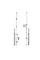
図19においては、サイズSをシフトさせる様子の一例を示している。同図において、横軸にサイズSが示されており、上段に第1顔検出処理にて設定されるサイズSを示し、下段に第1顔検出処理にて設定されるサイズSを示している。第1顔検出処理にて設定されるサイズSのうち、第1顔判定処理によって顔画像が存在すると判定されたサイズSを○で示し、顔画像が存在しないと判定されたサイズSを●で示している。第1顔検出処理においては、サイズSの大きい順から例えば20画素ずつ検出窓SWのサイズSを小さくしていく。第2顔判定処理においては、サイズSの設定周期を第1顔検出処理よりも小さい5画素とする。 FIG. 19 shows an example of how the size S is shifted. In the figure, the horizontal axis indicates the size S, the upper level indicates the size S set in the first face detection process, and the lower level indicates the size S set in the first face detection process. . Among the sizes S set in the first face detection process, the size S determined that the face image exists by the first face determination process is indicated by ○, and the size S determined that the face image does not exist is indicated by ●. Show. In the first face detection process, the size S of the detection window SW is reduced by, for example, 20 pixels from the largest size S. In the second face determination process, the setting cycle of the size S is set to 5 pixels smaller than the first face detection process.
第1顔判定処理によって顔画像が存在しない判定されたサイズSの間のサイズSの範囲(●と●の間)については顔検出の対象としない。一方、第1顔判定処理によって顔画像が存在すると判定されたサイズSの間のサイズSの範囲(○と○の間)については顔検出の対象とする。第1顔判定処理によって顔画像が存在する(顔と大きさがマッチする)と判定されたサイズSと、顔画像が存在しないと判定されたサイズSの間のサイズSの範囲(○と●の間)については、前者から後者のサイズSに向かってサイズSをシフトさせていき、顔が検出されなくなった時点で当該範囲のサイズSについての顔検出を終了させる。なお、本変形例の第1顔判定処理と第2顔判定処理で使用するニューラルネットワークNN1は含まれる顔画像の大きさにばらつきを持たせた学習画像データを使用して構築されており、ニューラルネットワークNN2は含まれる顔画像の大きさのばらつきが小さい学習画像データを使用して構築されているものとする。このようにすることにより、まず第1顔検出処理にて大まかなサイズSの絞り込みを行い、当該絞り込まれた範囲について詳細に第2顔判定処理を実行させることができる。従って、効率的かつ高精度に顔画像の大きさを特定することができる。 The range of the size S between the sizes S determined that the face image does not exist by the first face determination process (between ● and ●) is not subject to face detection. On the other hand, the range of size S (between ◯ and ◯) between sizes S determined that the face image exists by the first face determination process is set as a face detection target. The range of size S between the size S determined that the face image exists (the size matches the face) by the first face determination process and the size S determined that the face image does not exist (◯ and ● For (between), the size S is shifted from the former toward the latter size S, and when no face is detected, the face detection for the size S in the range is terminated. Note that the neural network NN1 used in the first face determination process and the second face determination process of the present modification is constructed using learning image data in which the size of the included face image varies, and the neural network It is assumed that the network NN2 is constructed using learning image data in which the size variation of the included face image is small. In this way, it is possible to first narrow down the size S roughly in the first face detection process, and to execute the second face determination process in detail for the narrowed range. Therefore, the size of the face image can be specified efficiently and with high accuracy.
3−2.変形例2
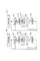
図20においては、本変形例の第1顔判定処理と第2顔判定処理の判定手法を模式的に示している。上述した実施形態ではニューラルネットワークNN1,NN2を使用したが本変形例では複数の判定器J,J…を複数段カスケード状に接続した判定手段を使用する。判定器J,J…はハードウェアによって実現されてもよいし、ソフトウェアによって実現されてもよい。各判定器J,J…は、それぞれ異なる種類(例えばフィルタが異なる)の単数または複数の特徴量CA,CA,CA…を入力し、それぞれ正または否の判定を出力する。各判定器J,J…は、それぞれ特徴量CA,CA,CA…の大小比較や閾値判定等の判定アルゴリズムを有しており、それぞれ独自の判定を実行する。次の段の各判定器J,J…は、前の段の判定器J,J…の正の出力に接続されており、前の段の判定器J,J…の出力が正であった場合のみ次の段の判定器J,J…が判定を実行する。いずれの段においても否の出力がなされた時点で、第1顔判定処理と第2顔判定処理を終了させ、顔画像が存在しない旨の判定を出力する。一方、各段の判定器J,J…がすべて正の出力をした場合には、第1顔判定処理と第2顔判定処理を終了させ、顔画像が存在する旨の判定を出力する。3-2.
FIG. 20 schematically shows the determination methods of the first face determination process and the second face determination process of the present modification. In the above-described embodiment, the neural networks NN1 and NN2 are used. However, in this modification, a determination unit in which a plurality of determination devices J, J. The determiners J, J... May be realized by hardware or may be realized by software. Each of the determiners J, J... Inputs one or more feature amounts CA, CA, CA... Of different types (for example, different filters), and outputs a positive or negative determination, respectively. Each of the determiners J, J... Has a determination algorithm such as a comparison of the feature amounts CA, CA, CA. Each of the next stage determiners J, J... Is connected to the positive output of the previous stage determiners J, J..., And the output of the previous stage determiners J, J. Only when this is the case, the next stage decision devices J, J... At any point in time when NO is output, the first face determination process and the second face determination process are terminated, and a determination that there is no face image is output. On the other hand, when all the determination devices J, J... At each stage output a positive value, the first face determination process and the second face determination process are terminated, and a determination that a face image exists is output.
図21は、本変形例にかかる判定手法における判定特性を示している。同図においては、上述した各判定器J,J…において使用される特徴量CA,CA,CA…の軸で定義される特徴量空間を示しており、最終的に顔画像が存在すると判定される窓画像データXDから得られる特徴量CA,CA,CA…の組み合わせで表される特徴量空間内の座標をプロットしている。顔画像が存在すると判定される窓画像データXDは一定の特徴を有しているため、特徴量空間における一定の領域に分布が見られると考えることができる。各判定器J,J…は、このような特徴量空間において境界平面を生成し、当該境界平面で区切られた空間のうち、前記分布が属する空間に判定対象の特徴量CA,CA,CA…の座標が存在している場合には、正を出力する。従って、各判定器J,J…をカスケード状に接続することにより、徐々に正と出力される空間を絞り込んでいくことができる。複数の境界平面によれば、複雑な形状の前記分布についても精度よく判定を行うことができる。 FIG. 21 shows determination characteristics in the determination method according to the present modification. This figure shows a feature space defined by the axes of the feature values CA, CA, CA,... Used in each of the above-described determiners J, J ..., and finally determines that a face image exists. Coordinates in the feature amount space represented by a combination of feature amounts CA, CA, CA... Obtained from the window image data XD. Since the window image data XD determined that the face image exists has a certain feature, it can be considered that a distribution is seen in a certain region in the feature amount space. Each of the determiners J, J... Generates a boundary plane in such a feature amount space, and among the spaces partitioned by the boundary plane, the determination target feature amounts CA, CA, CA. If the coordinate of exists, positive is output. Therefore, by connecting the determination devices J, J... In a cascade, it is possible to gradually narrow down the space in which the positive output is made. According to the plurality of boundary planes, it is possible to accurately determine the distribution having a complicated shape.
それぞれ異なる判定器J,J…を備える第1顔判定処理と第2顔判定処理を実行することにより、第1顔判定処理で絞り込んだ空間をさらに第2顔判定処理によって絞り込んでいくことができる。むろん、第1顔判定処理だけでなく、第1顔判定処理と第2顔判定処理を順次実行させた方が、判定結果が高精度となる。特に、第2顔判定処理の各判定器J,J…がx方向の位置を厳密化させる境界平面を適用するものとすれば、第2顔判定処理を実行させた方がx方向の位置に判定精度を高くすることができる。本発明では、顔画像が存在する可能性が高い位置やサイズについてのみ第2顔判定処理を実行するとともに、少ない個数の位置やサイズについてのみ第1顔判定処理を実行するため、効率的な処理を実現することができる。 By executing the first face determination process and the second face determination process each having different determiners J, J..., The space narrowed down by the first face determination process can be further narrowed down by the second face determination process. . Of course, not only the first face determination process but also the first face determination process and the second face determination process are sequentially executed, the determination result becomes highly accurate. In particular, if each of the determiners J, J... In the second face determination process applies a boundary plane that tightens the position in the x direction, the position where the second face determination process is performed becomes the position in the x direction. The determination accuracy can be increased. In the present invention, the second face determination process is executed only for positions and sizes where a face image is highly likely to exist, and the first face determination process is executed only for a small number of positions and sizes. Can be realized.
なお、以上においては、本発明の画像処理方法が、コンピュータ上で実行されるものを例示したが、例えばプリンタやデジタルスチルカメラやスキャナ等の画像機器にて実行されてもよい。プリンタにて本発明の画像処理方法を行えば、印刷の際に理想的な顔画像に近づく画像処理を実行することができる。むろん、プリンタは家庭用のものに限られず、業務用の写真プリントシステムにおいても適用することができる。さらに、プリンタのように印刷用紙上に画像処理結果を出力するものに限らず、フォトビューワのようにディスプレイ上に画像処理結果を出力する装置においても本発明を実現することができる。また、デジタルスチルカメラにて本発明の画像処理方法を行えば、理想的な肌色の顔画像となった撮影結果を得ることができる。さらに、人物認証を行うATM(Automated Teller
Machine)等においても本発明を適用することができる。さらに、ニューラルネットワークNNを使用して顔判定を行うものに限られず、上述した特徴量の特徴量空間における種々の判別手法を用いることも可能である。例えば、サポートベクタマシンを利用してもよい。In the above description, the image processing method of the present invention is exemplified as being executed on a computer. However, the image processing method may be executed by an image device such as a printer, a digital still camera, or a scanner. If the image processing method of the present invention is performed by a printer, it is possible to execute image processing that approximates an ideal face image during printing. Of course, the printer is not limited to a home printer, and can be applied to a business photo print system. Further, the present invention can be realized not only in a printer that outputs image processing results on a printing sheet but also in an apparatus that outputs image processing results on a display such as a photo viewer. Further, if the image processing method of the present invention is performed with a digital still camera, it is possible to obtain a photographing result that is an ideal skin-colored face image. Furthermore, ATM (Automated Teller) that performs person authentication
The present invention can also be applied to a machine). Further, the method is not limited to performing the face determination using the neural network NN, and various determination methods in the feature amount space of the feature amount described above can be used. For example, a support vector machine may be used.
10…コンピュータ、11…CPU、12…RAM、13…ROM、14…HDD、14a…プログラムデータ、14b…画像データ、15…GIF、16…VIF、17…IIF、18…バス、20…プリンタ、40…ディスプレイ、50a…キーボード、50b…マウス、PG1…OS、PG2…画像処理アプリケーション、PG2a…作業画像取得部、PG2b…検出窓設定部、PG2c…窓画像取得部、PG2d1…第1特徴量算出部、PG2d2…第2特徴量算出部、PG2e1…第1顔判定部、PG2e2…第2顔判定部、PG2f…画質調整部、PG3…プリンタドライバ。 DESCRIPTION OF
Claims (7)
Translated fromJapanese前記画像データに設定された検出窓の内側にオブジェクトが存在するか否かを判定する第1判定手段および第2判定手段を用意し、
前記画像データにおける複数の位置に設定された前記検出窓について前記第1判定手段による判定を実行させ、
前記第1判定手段によってオブジェクトが存在すると判定された位置同士の間の複数の位置の前記検出窓について前記第2判定手段による判定を実行させ、
前記第1判定手段によってオブジェクトが存在しないと判定された位置同士の間の位置の前記検出窓について前記第2判定手段による判定を実行させず、
前記第1判定手段によってオブジェクトが存在すると判定された位置と前記第1判定手段によってオブジェクトが存在しないと判定された位置の間の位置においては、前記第1判定手段によってオブジェクトが存在すると判定された位置から前記第1判定手段によってオブジェクトが存在しないと判定された位置に近づくように順に前記検出窓を移動させながら、前記検出窓について前記第2判定手段による判定を実行させるとともに前記第2判定手段によってオブジェクトが存在しないと最初に判定された位置から前記第1判定手段によってオブジェクトが存在しないと判定された位置との間の位置については前記第2判定手段による判定を実行させない、
ことを特徴とするオブジェクト検出方法。An object detection method for detecting an object from an image indicated by image data,
Preparing a first determination means and a second determination means for determining whether or not an object exists inside a detection window set in the image data;
Making the determination by the first determination means for the detection windows set at a plurality of positions in the image data;
The determination by the second determination unit is executed for the detection windows at a plurality of positions between the positions determined by the first determination unit that the object is present,
Without performing the determination by the second determination unit on the detection window at a position between the positions determined by the first determination unit that no object exists,
At the position between the position determined by the first determining means that the object is present and the position determined by the first determining means that the object is not present, the first determining means determines that the object is present.While the detection windowissequentiallymoved fromthe position so as to approach the position where the object is determined not to exist by the first determination unit, the determination by the second determination unit is performed on thedetection window , andthe second determination unit The second determination unit does not execute the determination between the position where the first determination unit determines that no object exists from the position where the first determination unit determines that the object does not exist.
An object detection method characterized by that.
前記第1判定手段によってオブジェクトが存在すると判定された大きさ同士の間の複数の大きさの前記検出窓について前記第2判定手段による判定を実行させ、
前記第1判定手段によってオブジェクトが存在しないと判定された大きさ同士の間の大きさの前記検出窓について前記第2判定手段による判定を実行させず、
前記第1判定手段によってオブジェクトが存在すると判定された大きさと前記第1判定手段によってオブジェクトが存在しないと判定された大きさの間の大きさにおいては、前記第1判定手段によってオブジェクトが存在しないと判定された大きさよりも前記第1判定手段によってオブジェクトが存在すると判定された大きさに近い大きさを優先させて設定した前記検出窓について前記第2判定手段による判定を実行させることを特徴とする請求項1〜請求項3のいずれか一項に記載のオブジェクト検出方法。The first determination unit performs determination on the detection windows set to a plurality of sizes in the image data,
The determination by the second determination unit is executed for the detection windows having a plurality of sizes between the sizes determined by the first determination unit as being present.
The determination by the second determination unit is not executed for the detection window having a size between the sizes determined by the first determination unit that the object is not present.
If there is no object between the size determined by the first determination means and the size determined by the first determination means that the object does not exist, the first determination means The determination by the second determination unit is performed on the detection window set by giving priority to a size close to the size determined by the first determination unit to be larger than the determined size.The object detection methodas described in any one of Claims 1-3 .
前記画像データに設定された検出窓の内側にオブジェクトが存在するか否かを判定する第1判定手段および第2判定手段と、
前記画像データにおける複数の位置に設定された前記検出窓について前記第1判定手段による判定を実行させる第1顔検出手段と、
前記第1判定手段によってオブジェクトが存在すると判定された位置同士の間の複数の位置の前記検出窓について前記第2判定手段による判定を実行させ、
前記第1判定手段によってオブジェクトが存在しないと判定された位置同士の間の位置の前記検出窓について前記第2判定手段による判定を実行させず、
前記第1判定手段によってオブジェクトが存在すると判定された位置と前記第1判定手段によってオブジェクトが存在しないと判定された位置の間の位置においては、前記第1判定手段によってオブジェクトが存在すると判定された位置から前記第1判定手段によってオブジェクトが存在しないと判定された位置に近づくように順に前記検出窓を移動させながら、前記検出窓について前記第2判定手段による判定を実行させるとともに前記第2判定手段によってオブジェクトが存在しないと最初に判定された位置から前記第1判定手段によってオブジェクトが存在しないと判定された位置との間の位置については前記第2判定手段による判定を実行させない第2顔検出手段とを具備することを特徴とするオブジェクト検出装置。An object detection device for detecting an object from an image indicated by image data,
First determination means and second determination means for determining whether or not an object exists inside a detection window set in the image data;
A first face detectingmeans Ru to execute the determination by said first determination means for set the detection window at a plurality of positions in the image data,
The determination by the second determination unit is executed for the detection windows at a plurality of positions between the positions determined by the first determination unit that the object is present,
Without performing the determination by the second determination unit on the detection window at a position between the positions determined by the first determination unit that no object exists,
At the position between the position determined by the first determining means that the object is present and the position determined by the first determining means that the object is not present, the first determining means determines that the object is present.While the detection windowissequentiallymoved fromthe position so as to approach the position where the object is determined not to exist by the first determination unit, the determination by the second determination unit is performed on thedetection window , andthe second determination unit The second face detecting meansthat does not execute the determination by the second determining means for the position between the position first determined that the object does not exist by the first determining means and the position determined by the first determining means that the object does not exist. An object detection apparatus comprising:
前記画像データに設定された検出窓の内側にオブジェクトが存在するか否かを判定する第1判定機能および第2判定機能と、
前記画像データにおける複数の位置に設定された前記検出窓について前記第1判定機能による判定を実行させる第1顔検出機能と、
前記第1判定機能によってオブジェクトが存在すると判定された位置同士の間の複数の位置の前記検出窓について前記第2判定機能による判定を実行させ、
前記第1判定機能によってオブジェクトが存在しないと判定された位置同士の間の位置の前記検出窓について前記第2判定機能による判定を実行させず、
前記第1判定機能によってオブジェクトが存在すると判定された位置と前記第1判定機能によってオブジェクトが存在しないと判定された位置の間の位置においては、前記第1判定機能によってオブジェクトが存在すると判定された位置から前記第1判定機能によってオブジェクトが存在しないと判定された位置に近づくように順に前記検出窓を移動させながら、前記検出窓について前記第2判定機能による判定を実行させるとともに前記第2判定機能によってオブジェクトが存在しないと最初に判定された位置から前記第1判定機能によってオブジェクトが存在しないと判定された位置との間の位置については前記第2判定機能による判定を実行させない第2顔検出機能とをコンピュータに実行させることを特徴とするコンピュータ読み取り可能なオブジェクト検出プログラム。A computer-readable object detection program for causing a computer to execute a function of detecting an object from an image indicated by image data,
A first determination function and a second determination function for determining whether or not an object exists inside a detection window set in the image data;
A first face detectingfunction Ru to execute the determination by the first determining function for set the detection window at a plurality of positions in the image data,
The determination by the second determination function is executed for the detection windows at a plurality of positions between the positions determined by the first determination function that the object is present,
Without performing the determination by the second determination function for the detection window between the positions determined by the first determination function that no object exists,
In the position between the position determined by the first determination function that the object is presentand the position determined by the first determination function that the object is not present,it is determined by the first determination function that the object is present.while moving the detection windowin order to be closer to the determined position and the object does not exist by the first determining function from theposition,the second determination function together to execute determination by said second determination function forsaid detection window The second face detection functionthat does not execute the determination by the second determination function for the position between the position first determined that the object does not exist by the first determination function and the position determined by the first determination function that the object does not exist A computer reading characterized by causing the computer to execute Possible object detection program.
前記画像データに設定された検出窓の内側にオブジェクトが存在するか否かを判定する第1判定手段および第2判定手段と、
前記画像データにおける複数の位置に設定された前記検出窓について前記第1判定手段による判定を実行させる第1顔検出手段と、
前記第1判定手段によってオブジェクトが存在すると判定された位置同士の間の複数の位置の前記検出窓について前記第2判定手段による判定を実行させ、
前記第1判定手段によってオブジェクトが存在しないと判定された位置同士の間の位置の前記検出窓について前記第2判定手段による判定を実行させず、
前記第1判定手段によってオブジェクトが存在すると判定された位置と前記第1判定手段によってオブジェクトが存在しないと判定された位置の間の位置においては、前記第1判定手段によってオブジェクトが存在すると判定された位置から前記第1判定手段によってオブジェクトが存在しないと判定された位置に近づくように順に前記検出窓を移動させながら、前記検出窓について前記第2判定手段による判定を実行させるとともに前記第2判定手段によってオブジェクトが存在しないと最初に判定された位置から前記第1判定手段によってオブジェクトが存在しないと判定された位置との間の位置については前記第2判定手段による判定を実行させない第2顔検出手段と、
前記第2判定手段による各判定に応じた画像処理を実行した前記画像データを印刷する印刷手段とを具備することを特徴とする印刷装置。A printing apparatus for printing an image indicated by image data,
First determination means and second determination means for determining whether or not an object exists inside a detection window set in the image data;
A first face detectingmeans Ru to execute the determination by said first determination means for set the detection window at a plurality of positions in the image data,
The determination by the second determination unit is executed for the detection windows at a plurality of positions between the positions determined by the first determination unit that the object is present,
Without performing the determination by the second determination unit on the detection window at a position between the positions determined by the first determination unit that no object exists,
At the position between the position determined by the first determining means that the object is present and the position determined by the first determining means that the object is not present, the first determining means determines that the object is present.While the detection windowissequentiallymoved fromthe position so as to approach the position where the object is determined not to exist by the first determination unit, the determination by the second determination unit is performed on thedetection window , andthe second determination unit The second face detecting meansthat does not execute the determination by the second determining means for the position between the position first determined that the object does not exist by the first determining means and the position determined by the first determining means that the object does not exist. When,
A printing apparatus comprising: a printing unit that prints the image data subjected to image processing according to each determination by the second determination unit.
Priority Applications (1)
| Application Number | Priority Date | Filing Date | Title |
|---|---|---|---|
| JP2008079362AJP4983682B2 (en) | 2008-03-25 | 2008-03-25 | Object detection method, object detection apparatus, object detection program, and printing apparatus |
Applications Claiming Priority (1)
| Application Number | Priority Date | Filing Date | Title |
|---|---|---|---|
| JP2008079362AJP4983682B2 (en) | 2008-03-25 | 2008-03-25 | Object detection method, object detection apparatus, object detection program, and printing apparatus |
Publications (2)
| Publication Number | Publication Date |
|---|---|
| JP2009237632A JP2009237632A (en) | 2009-10-15 |
| JP4983682B2true JP4983682B2 (en) | 2012-07-25 |
Family
ID=41251544
Family Applications (1)
| Application Number | Title | Priority Date | Filing Date |
|---|---|---|---|
| JP2008079362AExpired - Fee RelatedJP4983682B2 (en) | 2008-03-25 | 2008-03-25 | Object detection method, object detection apparatus, object detection program, and printing apparatus |
Country Status (1)
| Country | Link |
|---|---|
| JP (1) | JP4983682B2 (en) |
Families Citing this family (3)
| Publication number | Priority date | Publication date | Assignee | Title |
|---|---|---|---|---|
| JP5513960B2 (en)* | 2010-04-12 | 2014-06-04 | 株式会社メガチップス | Image processing device |
| JP5732773B2 (en)* | 2010-08-12 | 2015-06-10 | カシオ計算機株式会社 | Image identification device, image identification method, and program |
| JP7303144B2 (en)* | 2016-04-05 | 2023-07-04 | 株式会社島津製作所 | Radiation imaging apparatus, object detection program for radiographic image, and object detection method for radiographic image |
Family Cites Families (2)
| Publication number | Priority date | Publication date | Assignee | Title |
|---|---|---|---|---|
| JP4795737B2 (en)* | 2005-07-12 | 2011-10-19 | 富士フイルム株式会社 | Face detection method, apparatus, and program |
| JP4718952B2 (en)* | 2005-09-27 | 2011-07-06 | 富士フイルム株式会社 | Image correction method and image correction system |
- 2008
- 2008-03-25JPJP2008079362Apatent/JP4983682B2/ennot_activeExpired - Fee Related
Also Published As
| Publication number | Publication date |
|---|---|
| JP2009237632A (en) | 2009-10-15 |
Similar Documents
| Publication | Publication Date | Title |
|---|---|---|
| US9667841B2 (en) | Image processing apparatus and image processing method | |
| EP3407589B1 (en) | Image processing apparatus, image processing method, and storage medium | |
| EP2782065B1 (en) | Image-processing device removing encircling lines for identifying sub-regions of image | |
| JP4983684B2 (en) | Image processing apparatus, image processing method, and computer program for image processing | |
| JP5284994B2 (en) | Image processing device | |
| JP2012022652A (en) | Image processing apparatus, image processing method, and program | |
| JP4983682B2 (en) | Object detection method, object detection apparatus, object detection program, and printing apparatus | |
| JP2009237977A (en) | Image output control device, image output control method, image output control program, and printer | |
| JP5018587B2 (en) | Object detection method, object detection apparatus, object detection program, and computer-readable recording medium recording object detection program | |
| US8908988B2 (en) | Method and system for recovering a code image including blurring | |
| US12159371B2 (en) | Image processing apparatus, image forming system, image processing method, and non-transitory computer-readable storage medium | |
| JP5067224B2 (en) | Object detection apparatus, object detection method, object detection program, and printing apparatus | |
| US8254693B2 (en) | Image processing apparatus, image processing method and program | |
| US9894244B2 (en) | Image processing system and image processing method that perform correction of shifting bitmap data in a sub-scanning direction to cancel bending of and electro-photographic laser scanning line | |
| CN118233579A (en) | Data processing method, image forming apparatus, device, and storage medium | |
| JP2019175283A (en) | Recognition apparatus, recognition system, program, and position coordinate detecting method | |
| JP6584179B2 (en) | Information processing apparatus, information processing method, and computer program | |
| JP2009237976A (en) | Unit, method and program for controlling face image output, and print unit | |
| US10916032B2 (en) | Image processing apparatus, image processing program, image processing method, and image forming apparatus including the image processing apparatus | |
| US20170076187A1 (en) | Image processing apparatus and image processing method for estimating time required for print processing | |
| JP4983683B2 (en) | Object detection method, object detection apparatus, and object detection program | |
| JP5136705B2 (en) | Printing device | |
| JP2010160639A (en) | Method, device and program for detecting object, and printer | |
| JP4380308B2 (en) | Face area detection method and apparatus, program, and computer-readable storage medium storing face area detection program | |
| JP4710508B2 (en) | Image processing program and image processing apparatus |
Legal Events
| Date | Code | Title | Description |
|---|---|---|---|
| A621 | Written request for application examination | Free format text:JAPANESE INTERMEDIATE CODE: A621 Effective date:20110221 | |
| A977 | Report on retrieval | Free format text:JAPANESE INTERMEDIATE CODE: A971007 Effective date:20111118 | |
| A131 | Notification of reasons for refusal | Free format text:JAPANESE INTERMEDIATE CODE: A131 Effective date:20111122 | |
| A521 | Written amendment | Free format text:JAPANESE INTERMEDIATE CODE: A523 Effective date:20120118 | |
| TRDD | Decision of grant or rejection written | ||
| A01 | Written decision to grant a patent or to grant a registration (utility model) | Free format text:JAPANESE INTERMEDIATE CODE: A01 Effective date:20120327 | |
| A01 | Written decision to grant a patent or to grant a registration (utility model) | Free format text:JAPANESE INTERMEDIATE CODE: A01 | |
| A61 | First payment of annual fees (during grant procedure) | Free format text:JAPANESE INTERMEDIATE CODE: A61 Effective date:20120409 | |
| R150 | Certificate of patent or registration of utility model | Free format text:JAPANESE INTERMEDIATE CODE: R150 | |
| FPAY | Renewal fee payment (event date is renewal date of database) | Free format text:PAYMENT UNTIL: 20150511 Year of fee payment:3 | |
| S531 | Written request for registration of change of domicile | Free format text:JAPANESE INTERMEDIATE CODE: R313531 | |
| R350 | Written notification of registration of transfer | Free format text:JAPANESE INTERMEDIATE CODE: R350 | |
| LAPS | Cancellation because of no payment of annual fees |