JP4981627B2 - Linear actuator - Google Patents
Linear actuatorDownload PDFInfo
- Publication number
- JP4981627B2 JP4981627B2JP2007292233AJP2007292233AJP4981627B2JP 4981627 B2JP4981627 B2JP 4981627B2JP 2007292233 AJP2007292233 AJP 2007292233AJP 2007292233 AJP2007292233 AJP 2007292233AJP 4981627 B2JP4981627 B2JP 4981627B2
- Authority
- JP
- Japan
- Prior art keywords
- shaft
- housing
- bed
- linear actuator
- sub
- Prior art date
- Legal status (The legal status is an assumption and is not a legal conclusion. Google has not performed a legal analysis and makes no representation as to the accuracy of the status listed.)
- Expired - Fee Related
Links
- 230000002093peripheral effectEffects0.000claimsdescription14
- 230000007246mechanismEffects0.000description57
- 238000002680cardiopulmonary resuscitationMethods0.000description47
- 230000009467reductionEffects0.000description21
- 238000009434installationMethods0.000description20
- 230000009471actionEffects0.000description6
- 230000000694effectsEffects0.000description4
- 238000003780insertionMethods0.000description4
- 230000037431insertionEffects0.000description4
- 230000013011matingEffects0.000description3
- 230000000474nursing effectEffects0.000description3
- 238000012856packingMethods0.000description3
- 230000008878couplingEffects0.000description2
- 238000010168coupling processMethods0.000description2
- 238000005859coupling reactionMethods0.000description2
- 238000005192partitionMethods0.000description2
- 230000002265preventionEffects0.000description2
- 239000011347resinSubstances0.000description2
- 229920005989resinPolymers0.000description2
- 238000005096rolling processMethods0.000description2
- 238000006243chemical reactionMethods0.000description1
- 239000003638chemical reducing agentSubstances0.000description1
- 238000013461designMethods0.000description1
- 238000011161developmentMethods0.000description1
- 238000010586diagramMethods0.000description1
- 210000003127kneeAnatomy0.000description1
- 238000012986modificationMethods0.000description1
- 230000004048modificationEffects0.000description1
Images


Landscapes
- Connection Of Motors, Electrical Generators, Mechanical Devices, And The Like (AREA)
- Transmission Devices (AREA)
Description
Translated fromJapanese本発明は、リニアアクチュエータに関し、特に、電動送りねじ式リニアアクチュエータに係り、例えば、医療・介護用ベッドの寝床を上下させたり、背部や膝部の寝床を傾斜させたりするのに利用して有効なものに関する。 The present invention relates to a linear actuator, and more particularly to an electric feed screw type linear actuator. About things.
医療・介護用ベッドにおいては患者の寝食の負担を軽減するために、電動送りねじ式リニアアクチュエータによってベッドの寝床を上下させたり、背部や膝部の寝床を傾斜させたりすることが実施されている。 In the medical / nursing care bed, in order to reduce the burden of sleeping on the patient, the bed of the bed is moved up and down by the electric feed screw linear actuator, and the bed of the back and knees is inclined. .
このような医療・介護用ベッドにおいては、CPR機構と呼ばれるものが装備される場合がある。CPR機構とは、心肺蘇生施術等の緊急時にベッドをフラットにする機構である。
CPR機構は、どのような状況下であっても素早い確実な作動が要求され、他方、通常のベッドの使用時におけるリニアアクチュエータの作動に対しては制約を及ぼさないことが要求される。
このようなCPR機構を備えた介護用ベッドとしては、背もたれ板の裏面に設けられた操作レバーと、リニアアクチュエータの逆転防止機構部の作動を解除するための解除レバーとがケーブルによって連結されており、操作レバーを把持して背もたれ板を一旦持ち上げて逆転防止機構部に作用している負荷を除去することにより、解除レバーを簡単に解除方向に回転させることができるように構成されているものがある(特許文献1参照)。
また、CPR機構を備えたリニアアクチュエータとしては、ワンウエイクラッチの操作扞を操作レバーによって押動することにより、ワンウエイクラッチの連結を強制的に解除するように構成されているものがある(特許文献2参照)。
The CPR mechanism is required to operate quickly and reliably under any circumstances, and on the other hand, it is required not to limit the operation of the linear actuator during normal use of the bed.
As a nursing bed having such a CPR mechanism, an operation lever provided on the back surface of the backrest plate and a release lever for releasing the operation of the reverse rotation prevention mechanism portion of the linear actuator are connected by a cable. The release lever can be easily rotated in the release direction by holding the operation lever and lifting the backrest plate once to remove the load acting on the reverse rotation prevention mechanism. Yes (see Patent Document 1).
Moreover, as a linear actuator provided with the CPR mechanism, there is one configured to forcibly release the connection of the one-way clutch by pushing the operating rod of the one-way clutch with an operation lever (Patent Document 2). reference).
しかしながら、CPR機構の操作時にモータも同時に作動する制御となっている介護用ベッドおよびリニアアクチュエータにおいては、ワンウエイクラッチにフリクションが発生してしまう状況となっているために、CPR機構を作動させた時に、下限まで下げずに中間位置で停止させようとした場合には、スプラインで移動させる部品が動かずに、クラッチが再結合しない状況が発生してしまうという問題点がある。 However, in the care bed and the linear actuator that are controlled so that the motor is also operated at the same time when the CPR mechanism is operated, friction is generated in the one-way clutch, so when the CPR mechanism is operated. In the case where an attempt is made to stop at an intermediate position without lowering to the lower limit, there is a problem in that the parts that are moved by the spline do not move and the clutch is not re-coupled.
本発明の目的は、途中で停止可能なCPR機構を備えたリニアアクチュエータを提供することにある。 The objective of this invention is providing the linear actuator provided with the CPR mechanism which can be stopped on the way.
前記した課題を解決するための手段のうち代表的なものは、次の通りである。
(1)雄ねじ部を有するシャフトを回転自在に支承したハウジングと、前記雄ねじ部に螺合して前記シャフトの正逆回転によって進退する雌ねじ部材と、この雌ねじ部材に固定されて前記ハウジングに対して進退する移動筒と、前記シャフトにモータの回転を伝達する入力軸と、この入力軸と前記シャフトとの連結および解除を実行するクラッチと、を備えており、
前記クラッチは、
前記ハウジングの外周に前記入力軸の軸方向に摺動自在に支持されたスライダと、
前記ハウジングの外周に中間部を回動自在に枢支されて一端が前記スライダに係合されたレバーと、
このレバーの他端部に回動自在に一端部が連結されたリンクと、
このリンクの他端部に突設された作動ピンと、
前記作動ピンによって作動され、前記入力軸と前記シャフトとの連結および解除を実行する作動リングと、を備えている、
ことを特徴とするリニアアクチュエータ。
(2)前記スライダに前記モータをON・OFFさせるスイッチが設置されていることを特徴とする(1)のリニアアクチュエータ。
(3)前記入力軸には前記入力軸と共に回転するインナレースが装着されており、
前記インナレースの一端面には係合雄部が形成されており、
前記シャフトの外周面には前記ハウジング内に配されたカラーが装着されており、
前記カラーの一端面には前記係合雄部と係合する係合雌部が形成されている、
ことを特徴とする(1)または(2)に記載のリニアアクチュエータ。Typical means for solving the above-described problems are as follows.
(1) A housing that rotatably supports a shaft having a male screw portion, a female screw member that is screwed into the male screw portion and advances and retreats by forward and reverse rotation of the shaft, and is fixed to the female screw member with respect to the housing A moving cylinder that advances and retreats, an input shaft that transmits the rotation of the motor to the shaft, and a clutch that performs connection and release between the input shaft and the shaft,
The clutch is
A slider supported on the outer periphery of the housing so as to be slidable in the axial direction of the input shaft;
A lever pivotally supported on the outer periphery of the housing and having one end engaged with the slider;
A link having one end rotatably connected to the other end of the lever;
An operating pin protruding from the other end of the link;
An actuating ring that is actuated by the actuating pin to perform connection and release between the input shaft and the shaft;
A linear actuator characterized by that.
(2) linear actuatorbefore SL switch to ON · OFF theprevious SL motorto the slideris characterized inthat it is installed(1).
(3)An inner race that rotates together with the input shaft is attached to the input shaft,
An engagement male part is formed on one end surface of the inner race,
A collar disposed in the housing is attached to the outer peripheral surface of the shaft,
An engaging female part that engages with the engaging male part is formed on one end surface of the collar.
The linear actuator as described in (1) or (2) characterized by the above-mentioned.
前記した手段によれば、CPR機構を途中で停止させた際に、クラッチを確実に再結合させることができるので、CPR機構を途中で適正に停止させることができる。 According to the above-described means, when the CPR mechanism is stopped halfway, the clutch can be reliably re-coupled, so that the CPR mechanism can be properly stopped halfway.
以下、本発明の一実施の形態を図面に即して説明する。 Hereinafter, an embodiment of the present invention will be described with reference to the drawings.
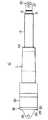
図1に示されているように、本実施の形態に係るリニアアクチュエータは、医療・介護用ベッド(以下、ベッドという。)の背部の寝床を起伏させるためのものとして構成されている。
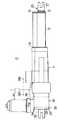
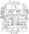
すなわち、図2および図3に示されているように、リニアアクチュエータ10はハウジング11と、ハウジング11に対して進退する移動筒12を備えており、図1に示されているように、リニアアクチュエータ10の固定端側であるハウジング11がベッド1のフレーム2に枢軸3によって回転自在に枢支され、リニアアクチュエータ10の自由端側である移動筒12の先端が背部の寝床(以下、寝床という。)4を起伏させるためのリンク5に枢軸6によって回転自在に連結されている。
図1(a)に示されているように、リニアアクチュエータ10の移動筒12が短縮した状態で、寝床4は水平に倒伏されており、リニアアクチュエータ10の移動筒12が伸長すると、寝床4は図1(b)に示されているように起立されるようになっている。As shown in FIG. 1, the linear actuator according to the present embodiment is configured to raise and lower the bed on the back of a medical / care bed (hereinafter referred to as a bed).
That is, as shown in FIGS. 2 and 3, the
As shown in FIG. 1A, the
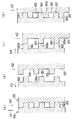
図2〜図5に示されているように、リニアアクチュエータ10のハウジング11は樹脂が使用されて略円筒形状に形成されており、図4および図5に示されているように、ハウジング11の一端部(以下、先端部とする。)には、支持筒13の一端部が嵌入されて支持されている。支持筒13は外径がハウジング11の内径と等しい丸パイプ形状に形成されている。ハウジング11の先端開口にはプラグ11Aが嵌入されている。
支持筒13の内周面には雌ねじ部材を回り止めするための回り止め部14が一対、略全長にわたってそれぞれ敷設されており、両回り止め部14、14は軸方向に一定幅一定高さに延在する細長いキー形状にそれぞれ形成されている。
図4(b)および図5(b)に示されているように、支持筒13の先端開口部には外周に鍔部を有する円筒形状に形成されたプラグ15が嵌入されている。As shown in FIGS. 2 to 5, the
A pair of
As shown in FIGS. 4B and 5B, a
支持筒13の筒心上にはシャフト16が軸架されている。シャフト16の支持筒13に対応する領域の外周には送り用の雄ねじ部17が形成されており、雄ねじ部17には雌ねじ部18が螺合された雌ねじ部材としてのナット19が進退自在に装着されている。
ナット19の基端部の外周部には、キー溝形状に形成された回り止め部20が一対それぞれ形成されており、両回り止め部20、20は支持筒13の内周面の一対の回り止め部14、14に軸方向に摺動自在にそれぞれ嵌合されている。したがって、ナット19は支持筒13に回り止め部14、20によって回り止めされた状態で、軸方向に摺動するようになっている。A
A pair of
シャフト16の外周におけるナット19の先端側の片脇には、スライダ21が摺動自在に嵌入されており、スライダ21の基端面はナット19の先端面に突合自在になっている。すなわち、スライダ21はナット19の進退に対応して原則的に追従するようになっている。
スライダ21の基端部の外周部には、キー溝形状に形成された回り止め部22が一対それぞれ形成されており、両回り止め部22、22は支持筒13の内周面の一対の回り止め部14、14に軸方向に摺動自在にそれぞれ嵌合されている。したがって、スライダ21は支持筒13に回り止め部14、22によって回り止めされた状態で、軸方向に摺動するようになっている。
スライダ21の先端部の外周には移動筒12の基端部が嵌入されており、移動筒12はスライダ21に固定部23によって固定されている。移動筒12は支持筒13よりも長い丸パイプ形状に形成されている。
移動筒12の先端部は支持筒13に嵌着されたプラグ15から先方に突き出されており、移動筒12の中間部はプラグ15によって摺動自在に支承された状態になっている。A
A pair of
The base end portion of the
The distal end portion of the moving
図4(b)および図5(b)に示されているように、移動筒12の先端部には、移動筒12をベッド1のリンク5に連結するための連結具25の基端部26が嵌入されており、連結具25は移動筒12の先端開口部に形成されたかしめ部24によって移動筒12に固定されている。
連結具25の先端部には取付孔27が開設されており、枢軸6が取付孔27に挿入されることにより、移動筒12がリンク5に連結されるようになっている。As shown in FIG. 4B and FIG. 5B, the distal end portion of the
An
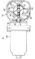
図2〜図6に示されているように、ハウジング11の基端側の端面にはサブハウジング30が当接されている。サブハウジング30は外径がハウジング11の外径と同一でハウジング11と反対側の端面が開口した大略四角形筒形状に形成されており、その開口部にはハウジング11をベッド1のフレーム2に連結するための連結具32の閉塞部33が被せられている。サブハウジング30および連結具32の閉塞部33はハウジング11に、複数本のビス29によって一緒に締結されている。
連結具32の外側端面にはブラケット34が突設されており、ブラケット34には取付孔35が開設されている。枢軸3が取付孔35に挿入されることにより、リニアアクチュエータ10の基端部がフレーム2に連結されるようになっている。As shown in FIGS. 2 to 6, the sub-housing 30 is in contact with the end face on the base end side of the
A
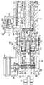
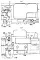
図3、図5(a)および図6に示されているように、サブハウジング30における開口部31と直角の位置にはモータ装着部36が突設されており、モータ装着部36にはモータ40が、回転軸41がサブハウジング30の中心線方向と直交するように配されて装着されている。モータ40の回転軸41の一端部はサブハウジン30の内部に挿入されて おり、回転軸41の中間部はモータ装着部36に設置された玉軸受37によって回転自在に支承されている。 As shown in FIG. 3, FIG. 5A and FIG. 6, a
回転軸41のサブハウジング30内の挿入部分の外周には、互いに反対向きの捩れを有する一対のウオーム(以下、右捩れウオームおよび左捩れウオームということがある。)42、43がそれぞれ一体的に形成されている。サブハウジング30の両ウオーム42、43にそれぞれ対向する位置であって回転軸41の互いに反対側の位置には、一対の支持軸44、45がサブハウジング30の中心線方向と平行にそれぞれ植設されている。
両支持軸44、45には一対のウオームホイール46、47がそれぞれ嵌合されて回転自在に支承されており、両ウオームホイール46、47は右捩れウオーム42および左捩れウオーム43にそれぞれ噛合されている。両ウオームホイール46、47には中間ギヤ48、49が軸芯合わせされて一体的にそれぞれ連設されており、両中間ギヤ48、49は同一の駆動ギヤ50にそれぞれ噛合されている。A pair of worms (hereinafter sometimes referred to as a right-handed worm and a left-handed worm) 42 and 43 having twists opposite to each other are integrally formed on the outer periphery of the insertion portion of the
A pair of
図5(a)に示されているように、駆動ギヤ50はサブハウジング30からハウジング11にわたって軸架されたサブシャフト52に滑りキー結合されることにより、軸方向に摺動自在で一体的に回転するように結合されている。
すなわち、サブハウジング30にはサブシャフト52がシャフト16の延長線上に配されて回転自在に支承されており、駆動ギヤ50はサブハウジング30内においてサブシャフト52の一端部の外周に嵌合されている。駆動ギヤ50の一端面にはキー溝51aが没設され、サブシャフト52にはキー51bが植設されており、キー溝51aとキー51bとが滑りキー結合されている。
このように駆動ギヤ50をサブシャフト52に軸方向に摺動自在で一体的に回転するように結合することにより、サブシャフト52に加わる軸方向(スラスト方向)の荷重(力)が駆動ギヤ50に伝達されるのを防止することができる。
但し、駆動ギヤ50はサブシャフト52に一体成形してもよい。As shown in FIG. 5 (a), the
That is, the sub-shaft 52 is disposed on the extension line of the
In this way, the
However, the
図4(a)および図5(a)に示されているように、ハウジング11のサブハウジング30に隣接する部分には軸受設置部53が形成されており、軸受設置部53には深溝玉軸受54が設置されている。深溝玉軸受54のインナレースはシャフト16の基端部の外周にカラー55を介して嵌合されており、シャフト16の基端部は深溝玉軸受54によって回転自在に支承されている。
深溝玉軸受54はシャフト16のラジアル荷重だけでなくシャフト16のスラスト荷重も支承し得るようにサイズが大きめに設定されており、軸受設置部53は深溝玉軸受54のアウタレースの外周面を摺動させる構造に構成されている。
このようにシャフト16を回転自在に支承するラジアル転がり軸受をサイズが大きめの深溝玉軸受54によって構成し、外周面で摺動し得るように設定することにより、シャフト16のスラスト荷重を支承するスラスト軸受を省略することができる。As shown in FIGS. 4A and 5A, a
The deep
Thus, the radial rolling bearing that rotatably supports the
ハウジング11における軸受設置部53に隣接する部位には、ワンウエイクラッチ設置部56が軸受設置部53と連続して形成されており、ワンウエイクラッチ設置部56にはワンウエイクラッチ57が設置されている。
ワンウエイクラッチ57は、互いに対になるアウタレース58およびインナレース59と、アウタレース58とインナレース59との間に転動自在に挟設された複数本のローラ60とを備えており、ローラ60がアウタレース58の内周面とインナレース59の外周面とに楔状に噛合することにより、シャフト16の一方向の回転時にアウタレース58とシャフト16とを連結するように構成されている。
ワンウエイクラッチ57のアウタレース58は深溝玉軸受54のアウタレースのみに接している。A one-way clutch installation portion 56 is formed continuously with the bearing
The one-way clutch 57 includes an
The
ハウジング11におけるサブハウジング30と隣接する部位には、ブレーキプレート設置部61が形成されており、ブレーキプレート設置部61にはベースプレート62が設置されている。
ベースプレート62は略円形リング形状に形成されており、サブシャフト52の外周に嵌合されている。ベースプレート62はサブハウジング30側の端面に突設された一対の係合部がサブハウジング30の対向面の係合穴にそれぞれ係合されることにより、回り止めされている。
ブレーキプレート63はベースプレート62よりも小径の略円形リング形状に形成されている。ブレーキプレート63はワンウエイクラッチ57のアウタレース58に回り止めされて嵌合されており、ブレーキプレート63とベースプレート62との合わせ面によって制動面が構成されている。A brake
The base plate 62 is formed in a substantially circular ring shape and is fitted to the outer periphery of the
The
本実施の形態においては、シャフト16にモータ40の回転を伝達する入力軸としてのサブシャフト52とシャフト16との間にはCPR機構65が介設されている。CPR機構65は通常のベッド1の使用時にはシャフト16とサブシャフト52とを連結しておき、心肺蘇生術を施す時等の緊急時にはシャフト16とサブシャフト52との連結を解除するクラッチとして構成されている。 In the present embodiment, a
図12および図13に示されているように、CPR機構65は操作部材としてのスライダ66を備えている。スライダ66は横長の略直方体形状に形成されており、ガイド孔67が略全長にわたって開設されている。ハウジング11の外周面には一対のガイド68、68が軸方向で並ぶように配置されてそれぞれ直角に突設されており、一対のガイド68、68はガイド孔67に摺動自在に嵌入されている。したがって、スライダ66は一対のガイド68、68によって軸方向に摺動自在に支持されている。
スライダ66の一端部には一対の係止穴66a、66aが没設されており、一対の係止穴66a、66aには一対のコントロールワイヤ69、69の一端部がそれぞれ係止されている(図13参照)。一対のコントロールワイヤ69、69の他端はベッド1の左右両側にそれぞれ配線され、ベッド1の左右に設置された操作レバー(図示せず)にそれぞれ係止される。つまり、スライダ66はベッド1の左右のいずれの側からも操作されるようになっている。
図12〜図15に示されているように、CPR機構65は一対のレバー101、101を備えており、一対のレバー101、101はスライダ66を挟んで互いに対称形に配置されている。両レバー101、101はハウジング11に互いに対称形に突設された一対の枢軸102、102によってそれぞれ回動自在に枢支されており、抜け止めピン103、103によってそれぞれ抜け止めされている。
一対のレバー101、101の一方の自由端部は互いに近接して対向されており、両自由端部は移動ピン104の両端部にそれぞれ回動自在に嵌合されている。移動ピン104はスライダ66の一端に形成されたU字形状の係合部66bに余裕をもって係合している。スライダ66はハウジング11に反力をとったスプリング70(図15参照)によって移動ピン104を押すように付勢されている。
レバー101の他方の自由端部にはピン105によってリンク106の一端部が回動自在に連結されている。リンク106の他端部には作動ピン107が直角に突設されており、作動ピン107はガイド孔71に挿入されている。As shown in FIGS. 12 and 13, the
A pair of locking
As shown in FIGS. 12 to 15, the
One free end of each of the pair of
One end of a
ハウジング11の側壁には長円形孔形状のガイド孔71が一対、周方向に互いに180度離れた位置においてハウジング11の軸心と平行に延在するように開設されている。
各ガイド孔71が開設されたハウジング11外周面には、各ガイドリング108が各パッキング109を挟んでそれぞれ固定されている。ガイドリング108およびパッキング109はガイド孔71よりも若干大きめの長円形リング形状に形成されている。ガイドリング108内にはリンク106が摺動自在に嵌入されており、作動ピン107はガイド孔71に挿入されている。作動ピン107はリンク106のガイドリング108内における移動に伴って、ガイド孔71内を軸方向に移動するようになっている。
なお、スライダ66はスライダカバー110Aによって被覆されており、レバー101はレバーカバー110Bによって被覆されている。A pair of oval hole-shaped guide holes 71 are formed in the side wall of the
Each
The
ハウジング11のワンウエイクラッチ設置部56内には、CPR機構65のクラッチのスリーブを兼用したインナレース59に作動力を伝達するための作動リング72が設置されており、作動リング72はワンウエイクラッチ57のアウタレース58の外周に摺動自在に嵌合されている。
作動リング72の外周面には環状溝73が没設されており、環状溝73には一対の作動ピン107、107の先端部が、ガイド孔71を挿通してそれぞれ挿入されている。作動リング72はリンク106の移動に伴う作動ピン107の軸方向への移動により、軸方向へ移動されるようになっている。
アウタレース58の外周におけるサブハウジング30側の端部には、スプリングシート74が嵌着されており、スプリングシート74と作動リング72のサブハウジング30側の端面との間には、リターンスプリング75が圧縮状態で介設されている。リターンスプリング75は作動リング72をサブハウジング30と反対側の方向に常時付勢するようになっている。In the one-way clutch installation portion 56 of the
An
A
作動リング72におけるワンウエイクラッチ57のローラ60と干渉しない位置には、CPR機構65のクラッチの係合ピンである一対の係合ピン76、76が径方向内向きにそれぞれ突設されており、両係合ピン76、76はアウタレース58にローラ60に干渉しないように開設された一対の挿通孔77、77にそれぞれ挿通されている。
ワンウエイクラッチ57のインナレース59の外周面には環状溝78が没設されており、環状溝78には挿通孔77に挿通された一対の係合ピン76、76の先端部がそれぞれ挿入されている。インナレース59はスライダ66に追従した作動リング72の軸方向への移動により係合ピン76、76および環状溝78を介して軸方向へ移動されるようになっている。
アウタレース58の内周におけるサブハウジング30側の端部には、スプリングシート79が嵌着されており、スプリングシート79とインナレース59のサブハウジング30側の端面との間には、リターンスプリング80が圧縮状態で介設されている。リターンスプリング80はインナレース59をサブハウジング30と反対側の方向に常時付勢するようになっている。A pair of engagement pins 76, 76 that are engagement pins of the clutch of the
An
A
インナレース59の内周にはサブシャフト52とシャフト16とが両端から嵌入されており、サブシャフト52はスプライン結合されている。すなわち、インナレース59の内周には雌スプライン81aが形成され、サブシャフト52の外周には雄スプライン81bが形成されており、雌スプライン81aと雄スプライン81bとが軸方向に摺動自在に嵌合されている。つまり、インナレース59はサブシャフト52に回り止めされた状態で、軸方向へ摺動し得るようになっており、シャフト16に対しては周方向へも軸方向へも摺動自在になっている。 A
インナレース59のシャフト16側の端面には、同一形状の3個の係合雄部82、82、82がそれぞれ形成されており、3個の係合雄部82、82、82は周方向に等間隔すなわち互いに120度離間した位置に配置されている。
3個の係合雄部82、82、82は、シャフト16にピン84によって固定されたカラー55のサブシャフト52側の端面に形成された3個の係合雌部83、83、83にそれぞれ係合および係合解除するように構成されている。3個の係合雌部83、83、83も互いに同一形状に形成されており、周方向に等間隔すなわち互いに120度離間した位置に配置されている。
係合雄部82の周方向の長さは、係合雌部83の周方向の長さよりも短く設定されている。
係合雄部82の周方向の長さをL1、係合雌部83の周方向の長さをL2とすると、係合雄部82の周方向の長さと係合雌部83の周方向の長さとは次式を満足するように設定することが好ましい。
L1/L2≦1/2
インナレース59がリターンスプリング80によって押し戻されている通常の状態においては、3個の係合雄部82、82、82は3個の係合雌部83、83、83にサブシャフト52側からそれぞれ進入して係合した状態になっており、インナレース59がスライダ66に追従した作動リング72の軸方向への移動によって軸方向へ移動された時には、3個の係合雄部82、82、82は3個の係合雌部83、83、83からサブシャフト52側へ離脱して係合を解除するようになっている。
つまり、インナレース59は入力軸としてのサブシャフト52とシャフト16との連結および解除を実行するクラッチを構成している。On the end surface of the
The three engaging
The circumferential length of the engaging
When the circumferential length of the engaging
L1 / L2 ≦ 1/2
In a normal state where the
That is, the
以上のように構成されたCPR機構65においては、心肺蘇生施術時に緊急にベッドをフラットにする際に、ベッド1の左右のいずれかのコントロールワイヤ69が引っ張られると、スライダ66が摺動されることにより、レバー101が回動されるため、作動ピン107がガイド孔71を移動する。これにより、作動リング72がリターンスプリング75の付勢力に抗してサブハウジング30の方向に移動される。この作動リング72の移動により、インナレース59がサブハウジング30の方向に移動される。このインナレース59の移動により、各係合雄部82が各係合雌部83との係合を解除するために、サブシャフト52とシャフト16との連結を迅速に解除することができる。
サブシャフト52との連結解除により、シャフト16は自由に回転可能な状態になるために、ベッド1の寝床4は緊急に倒れることが可能な状態になる。In the
By releasing the connection with the sub-shaft 52, the
図4(a)、図5(a)および図9に示されているように、ハウジング11における深溝玉軸受54のワンウエイクラッチ設置部56と反対側の片脇には、ポテンショセンサ設置部85が構成されている。ポテンショセンサ設置部85におけるシャフト16の外周にはウオームホイール86が一体回転するように嵌合されている。
ハウジング11の内部におけるポテンショセンサ設置部85には、ウオーム軸88がシャフト16の軸方向と直交する方向に配置されて、滑り軸受87によって回転自在に支持されている。ウオーム軸88の両端部には第一ウオーム89と第二ウオーム90とがそれぞれ刻設されており、第一ウオーム89はウオームホイール86に噛合されている。
ハウジング11の外部におけるポテンショセンサ設置部85にはポテンショセンサ91が、ポテンショセンサ91のセンサ軸92がウオーム軸88およびシャフト16に直交する方向になるように設置されている。センサ軸92にはドリブンギヤ93が一体回転するように固定されている。
ポテンショセンサ設置部85におけるポテンショセンサ91の片脇には、リダクションギヤ軸94が平行に軸架されており、リダクションギヤ軸94には互いに一体的に回転する大径リダクションギヤ95および小径リダクションギヤ96が回転自在に支承されている。小径リダクションギヤ96にはドリブンギヤ93が噛合されており、大径リダクションギヤ95には第二ウオーム90が噛合されている。
したがって、シャフト16の回転はウオームホイール86、第一ウオーム89、第二ウオーム90、大径リダクションギヤ95、小径リダクションギヤ96、ドリブンギヤ93を経由してセンサ軸92に伝達される。
ポテンショセンサ91はセンサ軸92の回転量を直線運動に変換して、電圧の大きさに変換するように構成されている。As shown in FIGS. 4 (a), 5 (a) and 9, a
A
A
A
Accordingly, the rotation of the
The
次に、作用および効果を説明する。
予め、リニアアクチュエータ10はベッド1に図1に示されているように組み付けられる。すなわち、枢軸3がベッド1のフレーム2に挿通されてリニアアクチュエータ10の連結具32に挿通されることにより、リニアアクチュエータ10は枢軸3によってベッド1のフレーム2に回転自在に枢支され、寝床4側の枢軸6がリニアアクチュエータ10の移動筒12側の連結具25に挿通されることにより、リニアアクチュエータ10は寝床4に枢軸6によって回転自在に連結される。Next, functions and effects will be described.
In advance, the
リニアアクチュエータ10がベッド1に組み付けられた後に、操作者が寝床4を起立させるべく正回転側の操作ボタンを押すことにより、図1(a)の状態から、モータ40が正方向に回転運転されると、回転軸41の駆動力が一対のウオーム42、43、ウオームホイール46、47、中間ギヤ48、49および駆動ギヤ50を介してサブシャフト52に伝達される。サブシャフト52の正回転はインナレース59の係合雄部82およびシャフト16の係合雌部83を介してシャフト16に伝達される。
このシャフト16の正回転時にはワンウエイクラッチ57とシャフト16との連結が解除されるために、シャフト16のみが正回転する。この際には、ワンウエイクラッチ57のアウタレース58に嵌合されたブレーキプレート63とベースプレート62との間の制動力は、起こらない。
ここで、モータ40の回転軸41の駆動力がサブシャフト52すなわちシャフト16に伝達される際に、回転軸41のトルクが一対のウオームホイール46、47に二分されるので、一対のウオームホイール46、47の外径を小さく設定することができる。
ウオームホイールの外径を小さく設定することにより、リニアアクチュエータ10を小型化することができる。
例えば、10000Nのリニアアクチュエータの設計において、従来はリニアアクチュエータの外径が直径110mmになるところ、本実施の形態に係るリニアアクチュエータにおいては、直径90mmに小型化することができた。After the
Since the connection between the one-way clutch 57 and the
Here, when the driving force of the
The
For example, in the design of a linear actuator of 10000 N, the outer diameter of the linear actuator is conventionally 110 mm, but the linear actuator according to the present embodiment can be downsized to 90 mm.
シャフト16がモータ40によって正回転されると、ナット19は支持筒13に沿って前進される状態になるために、ナット19に連結された移動筒12は支持筒13から押し出されて行く。この際、ナット19は樹脂製の支持筒13の回り止め部14に沿って摺動する。
なお、回り止め機構はリニアアクチュエータ10がベッド1に取り付けられていない時に移動筒12が回ってしまい、ポテンショセンサ91と移動筒12との位置関係に狂いが出てしまうのを防止するためのものであり、リニアアクチュエータ10がベッド1に取り付いてしまうと、移動筒12がベッド1に固定された状態になるので、不要になる。When the
The anti-rotation mechanism is for preventing the moving
移動筒12の前進によって移動筒12の連結具25に連結されたベッド1の寝床4が、図1(b)に示されているように起立されて行く。 The
他方、シャフト16の正回転は第一ウオーム89、第二ウオーム90、大径リダクションギヤ95、小径リダクションギヤ96、ドリブンギヤ93を経由してセンサ軸92に減速されて伝達される。センサ軸92の回転数はポテンショセンサ91によって電圧値に変換されて、ベッド1の作動を制御するコントローラ(図示せず)に送信される。
所定の上限位置に対応するポテンショ電圧を検出すると、コントローラはモータ40を自動的に止める。
ここで、シャフト16の回転をポテンショセンサ91のセンサ軸92に伝達するのに、ウオームホイール86およびウオーム軸88すなわちウオーム歯車減速装置を使用しているので、ポテンショセンサ91をシャフト16から離れた位置に配置することができ、ポテンショセンサ91の設置場所の自由度を高めることができる。
また、ウオーム歯車減速装置を使用することにより、減速比を大きく設定することができるので、大径リダクションギヤ95、小径リダクションギヤ96、ドリブンギヤ93の減速比を大きく設定しなくても済む。
なお、ウオーム軸88の第二ウオーム90は大径リダクションギヤ95や中間ギヤ等に置き換えてもよい。On the other hand, the forward rotation of the
When the potentiometer voltage corresponding to the predetermined upper limit position is detected, the controller automatically stops the
Here, since the
Moreover, since the reduction ratio can be set large by using the worm gear reduction device, the reduction ratios of the large
The
モータ40の運転が停止されると、ベッド1の寝床4の荷重(患者の体重等)がナット19へ、ナット19を後退させる方向の力として移動筒12を介して作用する状態になるために、シャフト16には移動筒12すなわち負荷側から逆回転させようとする負荷側逆回転作用力が、ナット19の雌ねじ部18およびシャフト16の送り用雄ねじ部17の作用によって加わる。
この負荷側逆回転作用力はアウタレース58とシャフト16とを連結させるように作用するために、ワンウエイクラッチ57のアウタレース58に嵌合されたブレーキプレート63とベースプレート62との合わせ面によって制動面が形成され、シャフト16は逆回転を阻止される。したがって、リニアアクチュエータ10は寝床4の荷重を持ち上げたままの状態で支持することができる。When the operation of the
Since the load side reverse rotation force acts to connect the
その後、操作者が寝床4を倒伏させるべく逆回転側の操作ボタンを押すことにより、モータ40が逆方向に回転運転されると、回転軸41の逆回転駆動力は一対のウオーム42、43、ウオームホイール46、47、中間ギヤ48、49および駆動ギヤ50を介してサブシャフト52に伝達される。サブシャフト52の逆回転はインナレース59の係合雄部82およびシャフト16の係合雌部83を介してシャフト16に伝達される。
シャフト16がモータ40によって逆回転されると、ナット19は支持筒13に沿って後退される状態になるために、ナット19に連結された移動筒12は支持筒13に引き込まれて行く。移動筒12の後退によって移動筒12の連結具25に連結されたベッド1の寝床4が倒されて行く。
この際にはシャフト16が逆回転するために、ワンウエイクラッチ57のアウタレース58とインナレース59とはローラ60によって連結した状態になるが、ブレーキプレート63とアウタレース58との間の制動力は、モータ40のシャフト16に対する駆動力よりも小さく設定されているので、ワンウエイクラッチ57はハウジング11に対して空回りすることにより、シャフト16のハウジング11に対する逆回転を許容する。
つまり、シャフト16がハウジング11に対して逆回転することにより、ナット19を支持筒13に沿って後退させるので、ナット19に連結された移動筒12を支持筒13に引き込み、移動筒12の連結具25に連結されたベッド1の寝床4を倒して行く。Thereafter, when the operator presses the operation button on the reverse rotation side to lie down on the
When the
At this time, since the
That is, when the
他方、シャフト16の逆回転は第一ウオーム89、第二ウオーム90、大径リダクションギヤ95、小径リダクションギヤ96、ドリブンギヤ93を経由してセンサ軸92に減速されて伝達される。センサ軸92の回転数はポテンショセンサ91によって電圧値に変換されて、ベッド1の作動を制御するコントローラ(図示せず)に送信される。
所定の下限位置に対応するポテンショ電圧を検出すると、コントローラはモータ40を自動的に止める。On the other hand, the reverse rotation of the
When the potentiometer voltage corresponding to the predetermined lower limit position is detected, the controller automatically stops the
モータ40の運転が停止されると、寝床4の荷重(患者の体重等)はベッド1のフレーム2によって機械的に支持されることにより、移動筒12にはナット19に後退させる方向の力が作用する状態にならないために、負荷側逆回転作用力がシャフト16に作用することはない。
但し、寝床4が倒伏した状態で、負荷側逆回転力がシャフト16に常に加わったとしても、シャフト16の逆回転は前述した作用によって防止されることになる。When the operation of the
However, even if the load-side reverse rotational force is constantly applied to the
次に、CPR機構65の緊急時の作動を、図10に即して説明する。
心肺蘇生術の実施等の緊急時に、図1(b)に示されているように、寝床4が起立された状態から寝床4を迅速にフラットにさせる際に、ベッド1の左右のいずれかのコントロールワイヤ69が操作レバーへの操作によって引っ張られると、図10(a)に示されているように、作動ピン107がガイド孔71内を移動される。
作動ピン107が移動されると、図10(b)に示されているように、作動リング72がリターンスプリング75の付勢力に抗してサブハウジング30の方向に移動され、この作動リング72の移動によってインナレース59がサブハウジング30の方向に移動される。
このインナレース59の移動によって各係合雄部82が各係合雌部83から離脱することにより、各係合雌部83との係合を解除するために、サブシャフト52とシャフト16との連結は解除した状態になる。
このシャフト16とサブシャフト52との連結解除により、シャフト16はインナレース59の内周で回転自由な状態になる。
この状態において、ベッド1の寝床4の荷重(患者の体重等)がナット19へ、ナット19を後退させる方向の力として移動筒12を介して作用する状態になるために、シャフト16には移動筒12すなわち負荷側から逆回転させようとする負荷側逆回転作用力が、ナット19の雌ねじ部18およびシャフト16の送り用雄ねじ部17の作用によって加わっている。
この負荷側逆回転作用力により、シャフト16はインナレース59の内周で逆回転されるために、寝床4は自重によって倒れることができる。Next, the emergency operation of the
In an emergency such as performing cardiopulmonary resuscitation, as shown in FIG. 1 (b), when the
When the
Each
By releasing the connection between the
In this state, the load on the
Due to the load-side reverse rotation force, the
ところで、CPR機構65の操作レバーが引かれると、寝床4は直ちに下降するが、操作レバーが途中で離されると、その位置で直ちに停止する必要がある。すなわち、CPR機構65は操作レバーが離されると、自動的に元の状態に復帰し、ベッドの通常の起伏作動を確保することができる状態に復帰する必要がある。
本実施の形態においては、サブシャフト52側のインナレース59とシャフト16側のカラー55との連結および解除の制御が、3個の係合雄部82と3個の係合雌部83とによって実行されるために、CPR機構65の操作レバーが途中で離された場合であっても、確実に元の状態に戻ることができる。By the way, when the operation lever of the
In the present embodiment, the connection and release control of the
次に、係合雄部と係合雌部の係合および係合解除の作動を図11によって説明する。
ベッドの通常の起伏作動時においては、インナレース59の係合雄部82とカラー55の係合雌部83とは、図11(a)に示されているように係合している。
図11(a)において、実線矢印A1はベッド上昇作動時のインナレース59の回転方向を示しており、破線矢印A2は負荷側逆転作用力の方向を示している。
CPR機構65の操作レバーが引かれると、図11(b)に矢印A3で示された方向にインナレース59がCPR機構65によって移動されることにより、係合雄部82は係合雌部83との係合を解除するために、カラー55すなわちシャフト16は負荷側逆転作用力の矢印A2の方向に回転する。
寝床4が下限に達する前の途中で、CPR機構65の操作レバーが離されると、図11(c)に矢印A4で示された方向にインナレース59がCPR機構65によって移動されるために、係合雄部82は係合雌部83と係合する元の位置に戻る。
このとき、図11(c)に示されているように、係合雄部82が隣り合う係合雌部83、83の隔壁部83aと突き当たる可能性が極僅かであるが有る。
本実施の形態においては、万一、係合雄部82が隔壁部83aと突き当たったとしても、係合雄部82の周方向の長さが係合雌部83の周方向の長さよりも短く設定されており、かつ、カラー55は負荷側逆転作用力によって矢印A2の方向に高速度で回転されているために、図11(d)示されているように、係合雄部82は係合雌部83に相対的に落ち込むことにより、係合雄部82は係合雌部83と係合する元の位置に確実に戻る。Next, the engagement and disengagement operations of the engaging male part and the engaging female part will be described with reference to FIG.
At the time of the normal raising / lowering operation of the bed, the engaging
In FIG. 11A, a solid line arrow A1 indicates the direction of rotation of the
When the operating lever of the
When the operation lever of the
At this time, as shown in FIG. 11 (c), there is a slight possibility that the engaging
In the present embodiment, even if the engaging
以上の作動により、CPR機構65の操作レバーが途中で離された場合であっても、3個の係合雄部82と3個の係合雌部83との再係合は確保することができる。
ところが、CPR機構65の操作レバーが途中で離された場合において、モータ40が運転されていると、サブシャフト52の雄スプライン81bとインナレース59の雌スプライン81aとの間にフリクションが発生する状況になることにより、インナレース59が図11(c)の矢印A4方向に移動することができないために、係合雄部82が係合雌部83に係合しない場合が起こる。With the above operation, even when the operating lever of the
However, when the operating lever of the
このため、図12、図13、図15に示されているように、本実施の形態に係るCPR機構65にはモータ停止機構111が設けられている。
モータ停止機構111は、モータ40の運転および停止を制御するスイッチ112を備えている。スイッチ112はスライダ66と一緒に移動するように設置されており、スイッチ112の検出子113はハウジング11に配置された被検出部114に接触するようになっている。For this reason, as shown in FIGS. 12, 13, and 15, the
The motor stop mechanism 111 includes a
次に、モータ停止機構111の作動を図15により説明する。
CPR機構65の操作レバーが操作されてスライダ66が移動すると、図15(b)に示されているように、スライダ66がスプリング70の付勢力に抗する方向に移動するために、検出子113が被検出部114を検出することにより、スイッチ112がONする。
スイッチ112がオンした状態で、CPR機構65の操作レバーが途中で離されると、スライダ66が元の方向に移動するために、図15(c)に示されているように、レバー101が回動する。このとき、スライダ66はレバー101の移動ピン104に押接するようにスプリング70によって常時付勢されていることにより、元の方向に移動するために、スイッチ112も元の方向に移動しOFFする。Next, the operation of the motor stop mechanism 111 will be described with reference to FIG.
When the operating lever of the
When the operating lever of the
このスイッチ112のOFFにより、モータ40の運転は自動的に停止されるので、CPR機構65の操作レバーが途中で離された場合において、サブシャフト52の雄スプライン81bとインナレース59の雌スプライン81aとの間にフリクションが発生する状況を回避することができる。
したがって、インナレース59が図11(c)の矢印A4方向に移動することができるために、係合雄部82が係合雌部83に再係合する。Since the operation of the
Therefore, since the
本実施の形態によれば、次のような効果を得ることができる。 According to the present embodiment, the following effects can be obtained.
1) モータの回転が伝達されるサブシャフト52と移動筒12を進退させるためのナット19が螺合されたシャフト16との間にサブシャフト52とシャフト16との連結および解除を実行するクラッチ(CPR機構)を介設することにより、ベッドの通常の使用時にはクラッチの連結によってモータの駆動力を移動筒12に確実に伝達することができるので、リニアアクチュエータの正常な作動を確保することができ、通常のベッドの使用を実現することができる。1) A clutch for connecting and releasing the sub-shaft 52 and the
2) 心肺蘇生術の実施等の緊急時にはクラッチ(CPR機構)の連結を解除させることにより、シャフト16を回転自由な状態に迅速に移行させることができるので、ベッド1の寝床4を自重によって迅速に倒すことができる。2) By releasing the clutch (CPR mechanism) in the event of an emergency such as cardiopulmonary resuscitation, the
3) CPR機構65の操作レバーが途中で離された時に、モータ40を停止させるモータ停止機構111を設けることにより、サブシャフト52側の雄スプライン81bとインナレース59の雌スプライン81aとの間にフリクションが発生する状況を防止することができるので、CPR機構65の操作レバーが途中で離された場合であっても、サブシャフト52側の係合雄部82をシャフト16側の係合雌部83と係合する元の位置に確実に戻すことができる。3) By providing a motor stop mechanism 111 that stops the
4) CPR機構65の操作レバーが途中で離された場合であっても、係合雄部82を係合雌部83と係合する元の位置に確実に戻すことができるので、ベッドの寝床4を操作レバーの解除によって指定された位置に直ちに、かつ、適正に急停止させることができる。4) Even when the operation lever of the
5) モータ停止機構111をコントロールワイヤ69の進退を検出するスライダ66と、スライダ66に設置されモータをON・0FFさせるスイッチとによって構成することにより、モータ停止機構を簡単に構成することができる。5) By configuring the motor stop mechanism 111 with the
なお、本発明は前記実施の形態に限定されるものではなく、その要旨を逸脱しない範囲で種々に変更が可能であることはいうまでもない。 Needless to say, the present invention is not limited to the above-described embodiment, and various modifications can be made without departing from the scope of the invention.
前記実施の形態では、ベッドの背部の寝床を起伏させる場合について説明したが、本発明に係るリニアアクチュエータは、ベッドの床面を上下させるように構成してもよい。
床面を上下させるように構成した場合には、緊急時に床面を直ちに下降させることができるという効果を奏することができる。In the above embodiment, the case where the bed on the back of the bed is raised and lowered has been described. However, the linear actuator according to the present invention may be configured to move the floor of the bed up and down.
In the case where the floor surface is configured to move up and down, there is an effect that the floor surface can be immediately lowered in an emergency.
前記実施の形態においては、リニアアクチュエータが医療・介護用ベッドに使用される場合について説明したが、本発明に係るアクチュエータはこれに限らず、自動車電装品等の用途にも適用することができる。 In the above-described embodiment, the case where the linear actuator is used for a medical / care bed has been described. However, the actuator according to the present invention is not limited to this and can be applied to applications such as automobile electrical components.
1…ベッド(医療・介護用ベッド)、2…フレーム、3…枢軸、4…寝床、5…リンク、6…枢軸、
10…リニアアクチュエータ、11…ハウジング、12…移動筒、13…支持筒、14…回り止め部、15…プラグ、16…シャフト、17…雄ねじ部、18…雌ねじ部、19…ナット(雌ねじ部材)、20…回り止め部、21…スライダ、22…回り止め部、23…固定部、24…かしめ部、
25…連結具、26…基端部、27…取付孔、
29…ビス、30…サブハウジング、31…開口部、32…連結具、33…閉塞部、34…ブラケット、35…取付孔、36…モータ装着部、37…玉軸受、
40…モータ、41…回転軸、42、43…ウオーム、44、45…支持軸、46、47…ウオームホイール、48、49…中間ギヤ、50…駆動ギヤ、
51a…キー溝、51b…キー、52…サブシャフト、53…軸受設置部、54…深溝玉軸受(スラスト軸受兼用ラジアル転がり軸受)、55…カラー、
56…ワンウエイクラッチ設置部、57…ワンウエイクラッチ、58…アウタレース、59…インナレース(CPR機構のクラッチのスリーブ)、60…ローラ、
61…ブレーキプレート設置部、62…ベースプレート、63…ブレーキプレート、
65…CPR機構、66…スライダ(操作部材)、67…ガイド孔、68…ガイド、69…コントロールワイヤ、70…スプリング、71…ガイド孔、72…作動リング、73…環状溝、74…スプリングシート、75…リターンスプリング、76…係合ピン、77…挿通孔、78…環状溝、79…スプリングシート、80…リターンスプリング、
81a…雌スプライン、81b…雄スプライン、82…係合雄部、83…係合雌部、83a…隔壁部、84…ピン、
85…ポテンショセンサ設置部、86…ウオームホイール、87…滑り軸受、88…ウオーム軸、89…第一ウオーム、90…第二ウオーム、91…ポテンショセンサ、92…センサ軸、93…ドリブンギヤ、94…リダクションギヤ軸、95…大径リダクションギヤ、96…小径リダクションギヤ、
101…レバー、102…枢軸、103…抜け止めピン、104…移動ピン、105…ピン、106…リンク、107…作動ピン、108…ガイドリング、109…パッキング、110A、110B…カバー、
111…モータ停止機構、112…スイッチ、113…検出子、114…被検出部。
1 ... bed (medical / care bed), 2 ... frame, 3 ... pivot, 4 ... bed, 5 ... link, 6 ... pivot,
DESCRIPTION OF
25 ... Connector, 26 ... Base end, 27 ... Mounting hole,
DESCRIPTION OF
DESCRIPTION OF
51a ... Key groove, 51b ... Key, 52 ... Sub shaft, 53 ... Bearing installation part, 54 ... Deep groove ball bearing (Thrust bearing combined radial rolling bearing), 55 ... Color,
56 ... One-way clutch installation part, 57 ... One-way clutch, 58 ... Outer race, 59 ... Inner race (CPR mechanism clutch sleeve), 60 ... Roller,
61 ... Brake plate installation part, 62 ... Base plate, 63 ... Brake plate,
65 ... CPR mechanism, 66 ... slider (operation member), 67 ... guide hole, 68 ... guide, 69 ... control wire, 70 ... spring, 71 ... guide hole, 72 ... acting ring, 73 ... annular groove, 74 ...
81a ... Female spline, 81b ... Male spline, 82 ... Engaging male part, 83 ... Engaging female part, 83a ... Bulkhead part, 84 ... Pin,
85: Potentiometer mounting portion, 86: Worm wheel, 87 ... Sliding bearing, 88 ... Worm shaft, 89 ... First worm, 90 ... Second worm, 91 ... Potentiometer, 92 ... Sensor shaft, 93 ... Driven gear, 94 ... Reduction gear shaft, 95 ... large diameter reduction gear, 96 ... small diameter reduction gear,
DESCRIPTION OF
111 ... Motor stop mechanism, 112 ... Switch, 113 ... Detector, 114 ... Detected part.
Claims (3)
Translated fromJapanese前記クラッチは、
前記ハウジングの外周に前記入力軸の軸方向に摺動自在に支持されたスライダと、
前記ハウジングの外周に中間部を回動自在に枢支されて一端が前記スライダに係合されたレバーと、
このレバーの他端部に回動自在に一端部が連結されたリンクと、
このリンクの他端部に突設された作動ピンと、
前記作動ピンによって作動され、前記入力軸と前記シャフトとの連結および解除を実行する作動リングと、を備えている、
ことを特徴とするリニアアクチュエータ。A housing that rotatably supports a shaft having a male screw portion, a female screw member that is screwed into the male screw portion and advances and retreats by forward and reverse rotation of the shaft, and a movement that is fixed to the female screw member and advances and retreats with respect to the housing A cylinder, an input shaft that transmits the rotation of the motor to the shaft, and a clutch that performs connection and release between the input shaft and the shaft,
The clutch is
A slider supported on the outer periphery of the housing so as to be slidable in the axial direction of the input shaft;
A lever pivotally supported on the outer periphery of the housing and having one end engaged with the slider;
A link having one end rotatably connected to the other end of the lever;
An operating pin protruding from the other end of the link;
An actuating ring that is actuated by the actuating pin to perform connection and release between the input shaft and the shaft;
A linear actuator characterized by that.
前記インナレースの一端面には係合雄部が形成されており、 An engagement male part is formed on one end surface of the inner race,
前記シャフトの外周面には前記ハウジング内に配されたカラーが装着されており、 A collar disposed in the housing is attached to the outer peripheral surface of the shaft,
前記カラーの一端面には前記係合雄部と係合する係合雌部が形成されている、 An engaging female part that engages with the engaging male part is formed on one end surface of the collar.
ことを特徴とする請求項1または請求項2に記載のリニアアクチュエータ。 The linear actuator according to claim 1 or 2, characterized by the above.
Priority Applications (1)
| Application Number | Priority Date | Filing Date | Title |
|---|---|---|---|
| JP2007292233AJP4981627B2 (en) | 2007-11-09 | 2007-11-09 | Linear actuator |
Applications Claiming Priority (1)
| Application Number | Priority Date | Filing Date | Title |
|---|---|---|---|
| JP2007292233AJP4981627B2 (en) | 2007-11-09 | 2007-11-09 | Linear actuator |
Publications (2)
| Publication Number | Publication Date |
|---|---|
| JP2009115298A JP2009115298A (en) | 2009-05-28 |
| JP4981627B2true JP4981627B2 (en) | 2012-07-25 |
Family
ID=40782643
Family Applications (1)
| Application Number | Title | Priority Date | Filing Date |
|---|---|---|---|
| JP2007292233AExpired - Fee RelatedJP4981627B2 (en) | 2007-11-09 | 2007-11-09 | Linear actuator |
Country Status (1)
| Country | Link |
|---|---|
| JP (1) | JP4981627B2 (en) |
Family Cites Families (5)
| Publication number | Priority date | Publication date | Assignee | Title |
|---|---|---|---|---|
| JP2618428B2 (en)* | 1988-03-30 | 1997-06-11 | 株式会社 マキタ | Power tool rotation control device |
| JP2812204B2 (en)* | 1994-08-10 | 1998-10-22 | 株式会社関西製作所 | Undulation mechanism of floor in bed |
| JP3800719B2 (en)* | 1997-05-06 | 2006-07-26 | 日本精工株式会社 | Electric linear actuator |
| DE29811566U1 (en)* | 1998-06-29 | 1998-08-20 | Dewert Antriebs- und Systemtechnik GmbH & Co KG, 32278 Kirchlengern | Electromotive furniture drive |
| JP5097551B2 (en)* | 2005-09-28 | 2012-12-12 | 株式会社ミツバ | Linear actuator |
- 2007
- 2007-11-09JPJP2007292233Apatent/JP4981627B2/ennot_activeExpired - Fee Related
Also Published As
| Publication number | Publication date |
|---|---|
| JP2009115298A (en) | 2009-05-28 |
Similar Documents
| Publication | Publication Date | Title |
|---|---|---|
| JP5225599B2 (en) | Linear actuator for bed | |
| JP5097551B2 (en) | Linear actuator | |
| US8210064B2 (en) | Actuator for lifting device | |
| US7594450B2 (en) | Quick-releasing linear actuator | |
| US8807311B2 (en) | Winch brake | |
| JP6587679B2 (en) | Linear actuator | |
| JP5520838B2 (en) | Actuator | |
| JP4633355B2 (en) | Linear actuator | |
| TWI550214B (en) | Linear actuator and cushion mechanism for the same | |
| CN105980166B (en) | Electric brake structure of casters | |
| JP5837702B2 (en) | Furniture linear drive | |
| JP2007187279A (en) | Linear actuator | |
| JP4981627B2 (en) | Linear actuator | |
| JP5123121B2 (en) | Linear actuator | |
| JP5049932B2 (en) | Linear actuator | |
| CN118040975A (en) | Linear actuator and medical bed having the same | |
| JP2010065771A (en) | Linear actuator | |
| CN104214296B (en) | Electric cylinder with position detection mechanism | |
| JP4585761B2 (en) | Linear actuator | |
| JP2007154954A (en) | Linear actuator | |
| JP2012096627A (en) | Electric parking brake | |
| JP4578801B2 (en) | Linear actuator | |
| JP4480998B2 (en) | Linear actuator | |
| CN104061303B (en) | Actuation device with quick release mechanism | |
| CN111743563B (en) | Detector drive for a nuclear medicine device and nuclear medicine device |
Legal Events
| Date | Code | Title | Description |
|---|---|---|---|
| A621 | Written request for application examination | Free format text:JAPANESE INTERMEDIATE CODE: A621 Effective date:20100608 | |
| A977 | Report on retrieval | Free format text:JAPANESE INTERMEDIATE CODE: A971007 Effective date:20111129 | |
| A131 | Notification of reasons for refusal | Free format text:JAPANESE INTERMEDIATE CODE: A131 Effective date:20111206 | |
| A521 | Request for written amendment filed | Free format text:JAPANESE INTERMEDIATE CODE: A523 Effective date:20120131 | |
| TRDD | Decision of grant or rejection written | ||
| A01 | Written decision to grant a patent or to grant a registration (utility model) | Free format text:JAPANESE INTERMEDIATE CODE: A01 Effective date:20120417 | |
| A01 | Written decision to grant a patent or to grant a registration (utility model) | Free format text:JAPANESE INTERMEDIATE CODE: A01 | |
| A61 | First payment of annual fees (during grant procedure) | Free format text:JAPANESE INTERMEDIATE CODE: A61 Effective date:20120420 | |
| FPAY | Renewal fee payment (event date is renewal date of database) | Free format text:PAYMENT UNTIL: 20150427 Year of fee payment:3 | |
| R150 | Certificate of patent or registration of utility model | Ref document number:4981627 Country of ref document:JP Free format text:JAPANESE INTERMEDIATE CODE: R150 Free format text:JAPANESE INTERMEDIATE CODE: R150 | |
| LAPS | Cancellation because of no payment of annual fees |