JP4980881B2 - Bone screw with joint - Google Patents
Bone screw with jointDownload PDFInfo
- Publication number
- JP4980881B2 JP4980881B2JP2007504232AJP2007504232AJP4980881B2JP 4980881 B2JP4980881 B2JP 4980881B2JP 2007504232 AJP2007504232 AJP 2007504232AJP 2007504232 AJP2007504232 AJP 2007504232AJP 4980881 B2JP4980881 B2JP 4980881B2
- Authority
- JP
- Japan
- Prior art keywords
- bone screw
- bone
- screw
- universal joint
- section
- Prior art date
- Legal status (The legal status is an assumption and is not a legal conclusion. Google has not performed a legal analysis and makes no representation as to the accuracy of the status listed.)
- Expired - Fee Related
Links
- 210000000988bone and boneAnatomy0.000titleclaimsabstractdescription71
- 230000002093peripheral effectEffects0.000claimsdescription7
- 238000002627tracheal intubationMethods0.000claimsdescription5
- 238000005553drillingMethods0.000claimsdescription2
- 238000010079rubber tappingMethods0.000claimsdescription2
- 229910000831SteelInorganic materials0.000description11
- 210000003109clavicleAnatomy0.000description11
- 239000010959steelSubstances0.000description11
- 210000003041ligamentAnatomy0.000description6
- 238000000034methodMethods0.000description4
- 230000008901benefitEffects0.000description3
- 230000000694effectsEffects0.000description3
- 230000008569processEffects0.000description3
- 238000001356surgical procedureMethods0.000description3
- 210000002303tibiaAnatomy0.000description3
- 238000005452bendingMethods0.000description2
- 230000005540biological transmissionEffects0.000description2
- 230000008859changeEffects0.000description2
- 230000006835compressionEffects0.000description2
- 238000007906compressionMethods0.000description2
- 210000000689upper legAnatomy0.000description2
- 206010065433Ligament ruptureDiseases0.000description1
- 230000009471actionEffects0.000description1
- 210000000544articulatio talocruralisAnatomy0.000description1
- 230000008878couplingEffects0.000description1
- 238000010168coupling processMethods0.000description1
- 238000005859coupling reactionMethods0.000description1
- 238000010586diagramMethods0.000description1
- 238000002513implantationMethods0.000description1
- 210000003205muscleAnatomy0.000description1
- 230000009467reductionEffects0.000description1
- 238000009958sewingMethods0.000description1
- 210000000323shoulder jointAnatomy0.000description1
- 230000006641stabilisationEffects0.000description1
- 238000011105stabilizationMethods0.000description1
- 230000000087stabilizing effectEffects0.000description1
Images


Classifications
- A—HUMAN NECESSITIES
- A61—MEDICAL OR VETERINARY SCIENCE; HYGIENE
- A61B—DIAGNOSIS; SURGERY; IDENTIFICATION
- A61B17/00—Surgical instruments, devices or methods
- A61B17/56—Surgical instruments or methods for treatment of bones or joints; Devices specially adapted therefor
- A61B17/58—Surgical instruments or methods for treatment of bones or joints; Devices specially adapted therefor for osteosynthesis, e.g. bone plates, screws or setting implements
- A61B17/68—Internal fixation devices, including fasteners and spinal fixators, even if a part thereof projects from the skin
- A61B17/84—Fasteners therefor or fasteners being internal fixation devices
- A61B17/86—Pins or screws or threaded wires; nuts therefor
- A61B17/8625—Shanks, i.e. parts contacting bone tissue
- A61B17/863—Shanks, i.e. parts contacting bone tissue with thread interrupted or changing its form along shank, other than constant taper
- A—HUMAN NECESSITIES
- A61—MEDICAL OR VETERINARY SCIENCE; HYGIENE
- A61B—DIAGNOSIS; SURGERY; IDENTIFICATION
- A61B17/00—Surgical instruments, devices or methods
- A61B17/56—Surgical instruments or methods for treatment of bones or joints; Devices specially adapted therefor
- A61B17/58—Surgical instruments or methods for treatment of bones or joints; Devices specially adapted therefor for osteosynthesis, e.g. bone plates, screws or setting implements
- A61B17/68—Internal fixation devices, including fasteners and spinal fixators, even if a part thereof projects from the skin
- A61B17/84—Fasteners therefor or fasteners being internal fixation devices
- A61B17/86—Pins or screws or threaded wires; nuts therefor
- A61B17/8685—Pins or screws or threaded wires; nuts therefor comprising multiple separate parts
Landscapes
- Health & Medical Sciences (AREA)
- Orthopedic Medicine & Surgery (AREA)
- Surgery (AREA)
- Life Sciences & Earth Sciences (AREA)
- Heart & Thoracic Surgery (AREA)
- Animal Behavior & Ethology (AREA)
- Engineering & Computer Science (AREA)
- Biomedical Technology (AREA)
- Neurology (AREA)
- Medical Informatics (AREA)
- Molecular Biology (AREA)
- Nuclear Medicine, Radiotherapy & Molecular Imaging (AREA)
- General Health & Medical Sciences (AREA)
- Public Health (AREA)
- Veterinary Medicine (AREA)
- Surgical Instruments (AREA)
- Prostheses (AREA)
- Glass Compositions (AREA)
Abstract
Description
Translated fromJapanese 本発明は、請求項1の上位概念に基づく骨ねじに関する。 The present invention relates to a bone screw based on the superordinate concept of
特許文献1から、ばね部品を持つ骨ねじは明らかである。骨ねじのシャフト内のばね部品は、骨ねじに若干の軸弾性(軸圧縮または弛緩)と若干の捩り、さらに半径方向全方位に若干の曲げを与えている。この周知の骨ねじは、ねじの圧縮効果の低下を防ぐ意図がある。 From
特許文献2から、弾性シャフトを持つ骨ねじは明らかになっている。前記構造の弾性については、幾つかの実施形態の中で記述されている。ここでも弾性結合が、ねじに若干の弾性を与えている。しかし回転トルクの伝動は、別の安定化器具または移植器具の支援なしには不可能である。 From
本発明はここで是正を講じるものである。本発明は、硬質性および、補助手段の支援を得ることのない回転トルクの全伝動を同時に維持しながら、その縦軸に相対的に全方位に撓むことができる。 The present invention takes corrective action here. The present invention can flex in all directions relative to its longitudinal axis while simultaneously maintaining rigidity and full transmission of rotational torque without the assistance of auxiliary means.
本発明は請求項1の特徴を有す骨ねじで与えられた課題を解決する。 The present invention solves the problem given by a bone screw having the features of
本発明により達成した長所は本質的に、発明による骨ねじの効果で、若干の撓み、およびそれによる相互の可動性が可能になるように骨を相互に結合できるという点にある。 The advantage achieved by the present invention is essentially that the effects of the bone screw according to the invention allow the bones to be coupled together so that some deflection and thereby mutual mobility is possible.
特別な実施形態においては、自在継手はカルダン継手から成る。その他の実施形態においては、自在継手は、多角形の、優先的には八角形の断面を有す玉頭、および玉頭の断面を収容するために好適な玉シェルを持つ玉軸受から成る。玉八角形の前記実施形態の長所は、従来型の自在継手に対し、少し限定された自由度の構造の簡単な設計である。In a special embodiment, theuniversal jointcomprises a cardan joint. In other embodiments, theuniversal joint hand, the polygon consists of ball bearings with a suitable ball shell to accommodate Tamaatama, and Tamaatama sectional have a octagonal cross section preferentially . The advantage of the embodiment of the ball octagon is a simple design with a somewhat limited degree of freedom over theconventional universal joint.
それ以外の実施形態においては、骨ねじは複数の自在継手を有す。この設計の長所は、骨ねじの自由度が大きくなることである。In other embodiments, the bone screw havinga plurality ofuniversal jointhands. The advantage of this design is the increased freedom of bone screws.
それ以外の実施形態においては、骨ねじはその縦軸に同軸に走り、貫く挿管を有す。挿管内へキルシュナイダー鋼線を導入することによって自在継手の封鎖を可能にする。In other embodiments, the bone screw runs coaxially about its longitudinal axis and has an intubation that penetrates. Theuniversal joint can be sealed by introducing Kirschneider steel wire into the intubation.
有利なことには、シャフトの長さ(隣接切片と末梢切片との両方の長さの和から成る)は一定である。 Advantageously, the length of the shaft (consisting of the sum of the lengths of both adjacent and peripheral sections) is constant.
優先的な実施形態においては、隣接切片も少なくとも部分的であっても、雄ねじを有す。もし骨部品間に特定の距離を維持したい場合、適切なドリルで骨部品を穿孔することができ、そのため、末梢切片のねじも、隣接切片のねじも螺嵌できる。両方の骨部品の距離は、固定した特定値に設定されたまま残る。このようにすれば、前記骨ねじは設定ねじとして使用される。その反面、両方の骨ねじ部品の距離変化を許すならば、ねじの隣接部分の収容に定めた孔を隣接部分の雄ねじよりも大きい直径に穿孔する。隣接ねじは、隣接骨部(例えば、鎖骨)に螺嵌しない。骨部品は、その相互距離を変更できる。最大距離はねじ頭により限定されるため、もちろんこれは特定の限度内のことである。前記の場合、骨ねじを引張ねじとして使用した。隣接部分を持つ骨ねじは、このように多方面に使用できる。例えば、骨部品が一緒に固まるようにしたい場合、骨部品を引張ねじとして使用し、例えば烏口突起まで螺入する。 In a preferential embodiment, the adjacent sections are also at least partially, with external threads. If it is desired to maintain a certain distance between the bone parts, the bone parts can be drilled with a suitable drill so that the screws of the peripheral section and of the adjacent section can be screwed together. The distance between both bone parts remains set to a fixed specific value. In this way, the bone screw is used as a setting screw. On the other hand, if the distance between both bone screw parts is allowed to change, the hole defined for accommodating the adjacent portion of the screw is drilled to a diameter larger than the male screw of the adjacent portion. The adjacent screw does not screw into the adjacent bone part (for example, clavicle). The bone parts can change their mutual distance. Of course, this is within certain limits as the maximum distance is limited by the screw head. In the above case, bone screws were used as tension screws. Bone screws with adjacent parts can thus be used in many ways. For example, if it is desired to set the bone parts together, the bone parts are used as tension screws, for example, screwed into the ostium process.
特別な実施形態においては、骨ねじはタッピンねじ、およびドリリングねじ、またはいずれか一方として造られている。 In a particular embodiment, the bone screw is made as a tapping screw and / or a drilling screw.
それ以外の実施形態においては、継手の撓み角が限定され、優先的には最大90°、目的に適っては最大30°にとる。 In other embodiments, the flexure angle of the joint is limited, preferentially up to 90 ° and up to 30 ° for the purpose.
本発明および本発明の改良を多数の実施例の部分的な概要図に基づき、以降にさらに詳細に説明する。 The invention and improvements of the invention will be described in more detail below with reference to partial schematic diagrams of a number of embodiments.
(図面の簡単な説明)
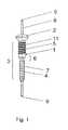
図1は、自在継手およびキルシュナー鋼線を持つ骨ねじの概観図である。
図2は、キルシュナー鋼線のない、直線にした状態の骨ねじの縦断面である。
図3は、キルシュナー鋼線のない、撓ませた状態の骨ねじの概観図である。
図4は、骨ねじのための自在継手に類似した変形玉軸受の部分縦断面図である。
図5は、肩の領域に移植された、図1から3に基づく骨ねじの概観図である。
図6は、距腿関節の領域に移植された、図1から3に基づく骨ねじの概観図である。(Brief description of the drawings)
FIG. 1 is a schematic view of a bone screw having auniversal joint and Kirschner steel wire.
FIG. 2 is a longitudinal section of a bone screw in a straight state without Kirschner wire.
FIG. 3 is a schematic view of a bent bone screw without Kirschner wire.
FIG. 4 is a partial longitudinal sectional view of a deformed ball bearing similar to auniversal joint for bone screws.
FIG. 5 is a schematic view of the bone screw according to FIGS. 1 to 3 implanted in the shoulder region.
FIG. 6 is a schematic view of the bone screw according to FIGS. 1 to 3 implanted in the area of the thigh joint.
図1から3に示した、発明による骨ねじ1は、頭部2、シャフト3、縦軸9、および貫通する中心挿管10を持つ。前記シャフト3は、前記頭部2と境を接する雄ねじ11付き隣接切片5、および自在継手6によってそれに固定されている、骨への導入に好適な雄ねじ4付き末梢切片7から成る。前記中心挿管10(図2)にキルシュナー鋼線8(図1)が導入されると前記自在継手6の封鎖が起こるため、前記骨ねじ1は(図1に示すように)撓むことができなくなる。The
図4に詳細に示すように、前記自在継手6は玉頭20付き玉継手、および前記隣接切片5に納められた玉シェル21から成る。前記玉頭20は八角形の断面を有し、前記玉シェル21は対応して合致させた、前記玉頭20の断面を収容するのに好適な八角形の幾何形状を持つ。前記幾何形状は、撓んだ状態においても前記骨ねじ1の回転を可能にしている。自在継手の替わりに従来型のカルダン継手を使用することもできる。As shown in detail in FIG. 4, the
図5には、肩の領域に使用した、鎖骨12および烏口突起13を結合するための発明による骨ねじ1を示す。普通の場合では、前記鎖骨12は靭帯、肩峰鎖骨靭帯16、菱形靱帯17、および円錐靱帯18によって位置を維持している。前記靭帯の破裂が起こると、前記鎖骨12は位置を維持できなくなり、そしていわゆる「ピアノ鍵盤効果」が起こる。前記鎖骨12は筋肉によって上方に引っ張られ、肩関節の領域では剥がれてしまう。技術の水準に基づく手術による処置は、鎖骨を縫い合わせ、特定の時間(数ヶ月間)鎖骨に力がかからないように硬質の骨ねじを収容することにある。残念ながら、硬質の骨ねじは、与えられた条件の元では破断してしまう。発明による骨ねじ1を(硬質のねじの替わりに)使用すると、相互に移動する鎖骨12と烏口突起13を結合できる。そのため縫い合わせた靭帯16、17、18は無負荷のまま残る。ここで両方の骨の撓みは前記骨ねじ1の自在継手6が生ぜしめる。しかし同時に両方の骨の距離は維持される。FIG. 5 shows a
肩の領域に使用するための手術技術を、以降に記述する。
a)キルシュナー鋼線8を、前記鎖骨12を通り越して前記烏口突起13に螺入する。
b)前記キルシュナー鋼線8を通して、ドリルを使い前記鎖骨12に貫通孔を穿孔する。それに対して、前記烏口突起13は穿孔しない。
c)前記骨ねじ1を、前記キルシュナー鋼線8によって、前記鎖骨12に予め穿孔した孔に入れ、その雄ねじ4によって前記烏口突起13に螺入する。前記キルシュナー鋼線8はここで前記瞬間においては、前記骨ねじ1を安定させながら、同時にそれを案内している。
d)前記キルシュナー鋼線8を取り外し、それにより前記骨ねじ1は撓めるようになる。Surgery techniques for use in the shoulder area are described below.
a) The Kirschner
b) A through hole is drilled in the
c) The
d) The
図6には、足関節の領域において、腓骨14と脛骨15を結合させるための発明による骨ねじ1の、それ以外の応用を示す。前記腓骨14と前記脛骨15の間に存在する帯19(靱帯結合)は破断して、前記腓骨14と前記脛骨15は互いに滑り合う。技術の水準に基づけば、前記帯19は縫合される。発明による骨ねじ1を使用することによって縫合された前記帯19は、両方の骨の距離を維持しながら負荷が取り除かれる。前記手術技術は図5を使って記述した技術と類似している。 FIG. 6 shows another application of the
1 骨ねじ
2 頭部
3 シャフト
4 雄ねじ
5 隣接切片
6 継手
7 末梢切片
8 キルシュナー鋼線
9 縦軸
11 雄ねじDESCRIPTION OF
Claims (9)
Translated fromJapanese前記頭部(2)と境を接する隣接切片(5)と;
前記隣接切片(5)に取り付けられかつ少なくとも部分的に雄ねじ(4)を有する、骨への導入に好適な末梢切片(7)とを有し、
前記隣接切片(5)と前記末梢切片(7)とは前記自在継手(6)によって互いに接続され、
前記隣接切片(5)はさらに少なくとも部分的に雄ねじ(11)を有することを特徴とする骨ねじ(1)。Head (2), a shaft (3), and bone screw (1) having a vertical axis (9)I der, the shaft(3),
An adjacent section (5) bordering the head (2);
A peripheral section (7) suitable for introduction into the bone, attached to said adjacent section (5) and having at least partly an external thread (4) ;
The adjacent section (5) and the peripheral section (7) are connected to each other by the universal joint (6),
Bone screw (1), characterized in that theadjacent section (5) further comprises at least partly a male screw (11 ).
Applications Claiming Priority (1)
| Application Number | Priority Date | Filing Date | Title |
|---|---|---|---|
| PCT/CH2004/000187WO2005092226A1 (en) | 2004-03-26 | 2004-03-26 | Articulated bone screw |
Publications (2)
| Publication Number | Publication Date |
|---|---|
| JP2007530103A JP2007530103A (en) | 2007-11-01 |
| JP4980881B2true JP4980881B2 (en) | 2012-07-18 |
Family
ID=34957107
Family Applications (1)
| Application Number | Title | Priority Date | Filing Date |
|---|---|---|---|
| JP2007504232AExpired - Fee RelatedJP4980881B2 (en) | 2004-03-26 | 2004-03-26 | Bone screw with joint |
Country Status (11)
| Country | Link |
|---|---|
| US (1) | US20070282342A1 (en) |
| EP (1) | EP1753355B1 (en) |
| JP (1) | JP4980881B2 (en) |
| KR (1) | KR101175376B1 (en) |
| CN (1) | CN1925805A (en) |
| AT (1) | ATE532473T1 (en) |
| AU (1) | AU2004317731B2 (en) |
| BR (1) | BRPI0418678B1 (en) |
| CA (1) | CA2560898C (en) |
| NZ (1) | NZ550050A (en) |
| WO (1) | WO2005092226A1 (en) |
Families Citing this family (45)
| Publication number | Priority date | Publication date | Assignee | Title |
|---|---|---|---|---|
| US9005245B2 (en)* | 2002-08-30 | 2015-04-14 | Arthrex, Inc. | Acromioclavicular joint fixation technique |
| WO2006034436A2 (en) | 2004-09-21 | 2006-03-30 | Stout Medical Group, L.P. | Expandable support device and method of use |
| US7951198B2 (en)* | 2005-05-10 | 2011-05-31 | Acumed Llc | Bone connector with pivotable joint |
| EP2023864B1 (en) | 2006-05-01 | 2019-07-10 | Stout Medical Group, L.P. | Expandable support device |
| US8114141B2 (en) | 2007-12-17 | 2012-02-14 | Synthes Usa, Llc | Dynamic bone fixation element and method of using the same |
| CN101224134B (en)* | 2008-01-29 | 2011-10-12 | 北京纳通投资有限公司 | Medical jiggle lag screw for medicine |
| US8597337B2 (en)* | 2008-02-14 | 2013-12-03 | Lloyd P. Champagne | Joint fusion device |
| WO2010056895A1 (en) | 2008-11-12 | 2010-05-20 | Stout Medical Group, L.P. | Fixation device and method |
| US20100211176A1 (en) | 2008-11-12 | 2010-08-19 | Stout Medical Group, L.P. | Fixation device and method |
| US8870876B2 (en) | 2009-02-13 | 2014-10-28 | Tarsus Medical Inc. | Methods and devices for treating hallux valgus |
| JP5460157B2 (en)* | 2009-07-15 | 2014-04-02 | ナカシマメディカル株式会社 | Clavicle fixation plate |
| US8715326B2 (en)* | 2009-08-28 | 2014-05-06 | Competitive Global Medical, Llc | Distal interphalangeal fusion device and method of use |
| US8277459B2 (en) | 2009-09-25 | 2012-10-02 | Tarsus Medical Inc. | Methods and devices for treating a structural bone and joint deformity |
| US8652141B2 (en)* | 2010-01-21 | 2014-02-18 | Tarsus Medical Inc. | Methods and devices for treating hallux valgus |
| US8529611B2 (en) | 2010-03-16 | 2013-09-10 | Competitive Global Medical, Llc | Distal interphalangeal fusion method and device |
| US8696719B2 (en) | 2010-06-03 | 2014-04-15 | Tarsus Medical Inc. | Methods and devices for treating hallux valgus |
| EP2608747A4 (en) | 2010-08-24 | 2015-02-11 | Flexmedex Llc | Support device and method for use |
| US8685067B2 (en) | 2010-12-21 | 2014-04-01 | Competitive Global Medical, Llc | Compression plate apparatus |
| US9138219B2 (en) | 2010-12-29 | 2015-09-22 | Tarsus Medical Inc. | Methods and devices for treating a syndesmosis injury |
| US20130085535A1 (en)* | 2011-09-21 | 2013-04-04 | Flexmedex, LLC | Support device and method |
| US9017404B2 (en) | 2012-01-23 | 2015-04-28 | Lloyd P. Champagne | Devices and methods for tendon repair |
| JP6174111B2 (en) | 2012-03-13 | 2017-08-02 | シンセス・ゲーエムベーハーSynthes GmbH | Dynamic bone fixation element |
| US9480515B2 (en) | 2012-07-12 | 2016-11-01 | Exsomed International IP, LLC | Metacarpal bone stabilization device |
| US20140343616A1 (en)* | 2013-04-22 | 2014-11-20 | Daniel Sellers | Arthrodesis compression device |
| WO2015050895A1 (en) | 2013-10-02 | 2015-04-09 | Exsomed Holding Company Llc | Full wrist fusion device |
| CN103479417B (en)* | 2013-10-14 | 2015-08-26 | 天津正天医疗器械有限公司 | Inferior tibiofibular joint hinge type flexible retainer |
| US9622523B2 (en) | 2014-01-06 | 2017-04-18 | Exsomed International IP, LLC | Ergonomic work gloves |
| US10716604B2 (en) | 2014-07-21 | 2020-07-21 | Maurho Medical, Inc. | Bone fusing device for fusing phalanges |
| US9579123B2 (en)* | 2014-09-19 | 2017-02-28 | Globus Medical, Inc. | Orthopedic stabilization devices and methods for installation thereof |
| US10478238B2 (en) | 2014-12-02 | 2019-11-19 | Activortho, Inc. | Active compression devices, methods of assembly and methods of use |
| WO2016186847A1 (en) | 2015-05-19 | 2016-11-24 | Exsomed International IP, LLC | Distal radius plate |
| US10245091B2 (en) | 2015-12-30 | 2019-04-02 | Exsomed Holding Company, Llc | Dip fusion spike screw |
| US11147604B2 (en) | 2016-01-12 | 2021-10-19 | ExsoMed Corporation | Bone stabilization device |
| US11224467B2 (en) | 2016-02-26 | 2022-01-18 | Activortho, Inc. | Active compression apparatus, methods of assembly and methods of use |
| CA3015902A1 (en) | 2016-02-26 | 2017-08-31 | Activortho, Inc. | Active compression apparatus, methods of assembly and methods of use |
| US10194923B2 (en) | 2016-05-10 | 2019-02-05 | Exsomed International IP, LLC | Tool for percutaneous joint cartilage destruction and preparation for joint fusion |
| DE102016011947A1 (en) | 2016-10-05 | 2018-04-05 | Bluewater Medical GmbH | Screw with a head part, a threaded part and a connecting part |
| US11147681B2 (en) | 2017-09-05 | 2021-10-19 | ExsoMed Corporation | Small bone angled compression screw |
| JP2020532407A (en) | 2017-09-05 | 2020-11-12 | エクソームド コーポレーションExsomed Corporation | Threaded intramedullary nail for radial cortex fixation |
| US11191645B2 (en) | 2017-09-05 | 2021-12-07 | ExsoMed Corporation | Small bone tapered compression screw |
| US11179234B2 (en) | 2017-09-15 | 2021-11-23 | Paragon 28, Inc. | Ligament fixation system, implants, devices, and methods of use |
| WO2019071273A1 (en) | 2017-10-06 | 2019-04-11 | Paragon 28, Inc. | Ligament fixation system, implants, devices, and methods of use |
| ES2955370T3 (en) | 2017-10-25 | 2023-11-30 | Paragon 28 Inc | Fixation system for ligaments, implants and devices with compression cap |
| KR101981107B1 (en)* | 2018-12-07 | 2019-05-22 | 의료법인 명지의료재단 | Reverse compression bone screw |
| CA3153728A1 (en) | 2019-09-12 | 2021-03-18 | Paragon 28, Inc. | Dynamic fixation implant and method of use |
Family Cites Families (38)
| Publication number | Priority date | Publication date | Assignee | Title |
|---|---|---|---|---|
| US3054321A (en)* | 1959-07-15 | 1962-09-18 | Macchia Anthony | Screw assembly with ball and socket connection |
| US4955916A (en)* | 1989-05-01 | 1990-09-11 | Techmedica, Inc. | Thumb joint prosthesis |
| DE3942326A1 (en)* | 1989-12-21 | 1991-06-27 | Haerle Anton | SCREW AS AN OSTEOSYNTHESIS TOOL |
| DE9300056U1 (en)* | 1993-01-09 | 1993-03-04 | Hirsch, Joachim, 8480 Weiden | Arrangement comprising a special screw, a mechanical connecting element and a threaded bolt |
| DE4307576C1 (en)* | 1993-03-10 | 1994-04-21 | Biedermann Motech Gmbh | Bone screw esp. for spinal column correction - has U=shaped holder section for receiving straight or bent rod |
| FR2704142B1 (en)* | 1993-04-23 | 1995-07-07 | Jbs Sa | Ball joint prosthesis for the basal joint of the thumb. |
| JPH06337018A (en)* | 1993-05-27 | 1994-12-06 | Daishin Seisakusho:Kk | Shaft coupling |
| US5433548A (en)* | 1993-09-22 | 1995-07-18 | Roberts Tool International (Usa), Inc. | Universal joint for torque transmitting tools |
| US5628740A (en)* | 1993-12-23 | 1997-05-13 | Mullane; Thomas S. | Articulating toggle bolt bone screw |
| US6004322A (en)* | 1994-10-25 | 1999-12-21 | Sdgi Holdings, Inc. | Modular pedicle screw system |
| US5591166A (en)* | 1995-03-27 | 1997-01-07 | Smith & Nephew Richards, Inc. | Multi angle bone bolt |
| US5984970A (en)* | 1996-03-13 | 1999-11-16 | Bramlet; Dale G. | Arthroplasty joint assembly |
| US5800435A (en)* | 1996-10-09 | 1998-09-01 | Techsys, Llc | Modular spinal plate for use with modular polyaxial locking pedicle screws |
| NL1005234C2 (en)* | 1997-02-10 | 1998-08-11 | Novarticulate Bv | Hip replacement and a method of placing such a hip replacement. |
| IES77331B2 (en)* | 1997-06-03 | 1997-12-03 | Tecos Holdings Inc | Pluridirectional and modulable vertebral osteosynthesis device of small overall size |
| US5891146A (en)* | 1997-10-15 | 1999-04-06 | Applied Biological Concepts, Inc. | Wedge orthopedic screw |
| US6050997A (en)* | 1999-01-25 | 2000-04-18 | Mullane; Thomas S. | Spinal fixation system |
| DE19920544C2 (en)* | 1999-05-05 | 2001-06-07 | Adolf Wuerth Gmbh & Co Kg | Joint for a tool |
| WO2001012054A2 (en)* | 1999-08-17 | 2001-02-22 | Pioneer Laboratories | Bone connector system |
| US6375657B1 (en)* | 2000-03-14 | 2002-04-23 | Hammill Manufacturing Co. | Bonescrew |
| JP3817112B2 (en)* | 2000-04-04 | 2006-08-30 | 株式会社村上開明堂 | Electric retractable door mirror drive structure |
| US6443467B1 (en)* | 2000-09-22 | 2002-09-03 | Racing Strollers, Inc. | Baby stroller with interchangeable front wheel support structures |
| US6908469B2 (en)* | 2000-10-04 | 2005-06-21 | Synthes (Usa) | Compact maxillary distractor |
| EP1203569B1 (en)* | 2000-11-03 | 2008-10-15 | Finsbury (Development) Limited | Metacarpo-phalangeal joint prosthesis |
| DE10129490A1 (en)* | 2001-06-21 | 2003-01-02 | Helmut Mueckter | Implantable screw for stabilization of joint or bone fracture, has flexible shaft which interconnects proximal head portion and distal insertion portion of elongated screw body |
| US6887242B2 (en)* | 2001-10-17 | 2005-05-03 | Ortho Innovations, Llc | Split ring bone screw for a spinal fixation system |
| US6623485B2 (en)* | 2001-10-17 | 2003-09-23 | Hammill Manufacturing Company | Split ring bone screw for a spinal fixation system |
| FR2831048B1 (en)* | 2001-10-18 | 2004-09-17 | Ldr Medical | PROGRESSIVE APPROACH OSTEOSYNTHESIS DEVICE AND PRE-ASSEMBLY PROCESS |
| US7335201B2 (en)* | 2003-09-26 | 2008-02-26 | Zimmer Spine, Inc. | Polyaxial bone screw with torqueless fastening |
| US6949101B2 (en)* | 2002-03-29 | 2005-09-27 | Depuy Orthopaedics, Inc. | Medical instrument for milling a curved path in bone and procedure |
| US6740086B2 (en)* | 2002-04-18 | 2004-05-25 | Spinal Innovations, Llc | Screw and rod fixation assembly and device |
| FR2842093B1 (en)* | 2002-07-12 | 2005-04-15 | Scient X | BONE ANCHORING DEVICE WITH SPHERICAL JOINT |
| AU2003287273C1 (en)* | 2002-10-30 | 2010-01-07 | Zimmer Spine, Inc. | Spinal stabilization system insertion and methods |
| US7044953B2 (en)* | 2003-02-27 | 2006-05-16 | Stryker Leibinger Gmbh & Co. Kg | Compression bone screw |
| US7377923B2 (en)* | 2003-05-22 | 2008-05-27 | Alphatec Spine, Inc. | Variable angle spinal screw assembly |
| US7875060B2 (en)* | 2003-09-24 | 2011-01-25 | Spinefrontier, LLS | Multi-axial screw with a spherical landing |
| US7819902B2 (en)* | 2004-02-27 | 2010-10-26 | Custom Spine, Inc. | Medialised rod pedicle screw assembly |
| US20050245933A1 (en)* | 2004-05-03 | 2005-11-03 | Sevrain Lionel C | Multi coaxial screw system |
- 2004
- 2004-03-26JPJP2007504232Apatent/JP4980881B2/ennot_activeExpired - Fee Related
- 2004-03-26EPEP04723488Apatent/EP1753355B1/ennot_activeExpired - Lifetime
- 2004-03-26NZNZ550050Apatent/NZ550050A/enunknown
- 2004-03-26BRBRPI0418678-8B1Apatent/BRPI0418678B1/ennot_activeIP Right Cessation
- 2004-03-26CNCNA2004800423320Apatent/CN1925805A/enactivePending
- 2004-03-26ATAT04723488Tpatent/ATE532473T1/enactive
- 2004-03-26WOPCT/CH2004/000187patent/WO2005092226A1/enactiveApplication Filing
- 2004-03-26AUAU2004317731Apatent/AU2004317731B2/ennot_activeCeased
- 2004-03-26USUS10/593,600patent/US20070282342A1/ennot_activeAbandoned
- 2004-03-26CACA2560898Apatent/CA2560898C/ennot_activeExpired - Fee Related
- 2006
- 2006-09-26KRKR1020067019932Apatent/KR101175376B1/ennot_activeExpired - Fee Related
Also Published As
| Publication number | Publication date |
|---|---|
| KR20070008603A (en) | 2007-01-17 |
| ATE532473T1 (en) | 2011-11-15 |
| US20070282342A1 (en) | 2007-12-06 |
| AU2004317731A1 (en) | 2005-10-06 |
| JP2007530103A (en) | 2007-11-01 |
| NZ550050A (en) | 2009-03-31 |
| BRPI0418678A (en) | 2007-06-05 |
| CA2560898A1 (en) | 2005-10-06 |
| EP1753355A1 (en) | 2007-02-21 |
| EP1753355B1 (en) | 2011-11-09 |
| CA2560898C (en) | 2012-11-13 |
| CN1925805A (en) | 2007-03-07 |
| AU2004317731B2 (en) | 2010-03-25 |
| BRPI0418678B1 (en) | 2013-10-01 |
| KR101175376B1 (en) | 2012-08-20 |
| WO2005092226A1 (en) | 2005-10-06 |
Similar Documents
| Publication | Publication Date | Title |
|---|---|---|
| JP4980881B2 (en) | Bone screw with joint | |
| US20230157708A1 (en) | Intramedullary fixation system for management of pelvic and acetabular fractures | |
| RU2604032C2 (en) | Fixing system and feeding device used in it | |
| EP2493393B1 (en) | Threaded suture anchor | |
| JP5014549B2 (en) | Palm-side fixing device | |
| JP6091437B2 (en) | Bone screw with multi-thread profile fixed far-cortically and flexibly engaged to bone | |
| US11116494B2 (en) | Compliant inserter for implants | |
| WO2006055448A1 (en) | Off-axis anchor guidance system | |
| US20100256690A1 (en) | Locking Spiral Anchoring System | |
| JP2005504581A (en) | Device for preventing rotation of bone fragments | |
| JP2003529414A5 (en) | ||
| US20190336170A1 (en) | Method of correcting hallux varus joint deformity | |
| US10188428B2 (en) | Subcutaneous implantable device for gradually aligning a spine | |
| EP3253300B1 (en) | Articulating needle | |
| JP2007190115A (en) | Internal fixing material for distal radius | |
| CN217593035U (en) | Tibiofibular syndesmosis fixing device | |
| ZA200607948B (en) | Articulated bone screw | |
| KR102084625B1 (en) | Ligament fixing screw | |
| JP2016198125A (en) | Entry jig and method of fixing member using the entry jig | |
| KR200383131Y1 (en) | headless cone screw thread on outside of head | |
| KR101774390B1 (en) | Extension type suture anchor | |
| CN114305636A (en) | Patella fracture nail cable locking device | |
| JP2010207289A (en) | Medical shooting staple | |
| US20130172946A1 (en) | Implant module and method for repairing avulsion fracture |
Legal Events
| Date | Code | Title | Description |
|---|---|---|---|
| RD02 | Notification of acceptance of power of attorney | Free format text:JAPANESE INTERMEDIATE CODE: A7422 Effective date:20080117 | |
| A131 | Notification of reasons for refusal | Free format text:JAPANESE INTERMEDIATE CODE: A131 Effective date:20091118 | |
| A521 | Request for written amendment filed | Free format text:JAPANESE INTERMEDIATE CODE: A523 Effective date:20100114 | |
| A02 | Decision of refusal | Free format text:JAPANESE INTERMEDIATE CODE: A02 Effective date:20100310 | |
| A601 | Written request for extension of time | Free format text:JAPANESE INTERMEDIATE CODE: A601 Effective date:20120201 | |
| A602 | Written permission of extension of time | Free format text:JAPANESE INTERMEDIATE CODE: A602 Effective date:20120206 | |
| A521 | Request for written amendment filed | Free format text:JAPANESE INTERMEDIATE CODE: A523 Effective date:20120302 | |
| A01 | Written decision to grant a patent or to grant a registration (utility model) | Free format text:JAPANESE INTERMEDIATE CODE: A01 | |
| A61 | First payment of annual fees (during grant procedure) | Free format text:JAPANESE INTERMEDIATE CODE: A61 Effective date:20120419 | |
| FPAY | Renewal fee payment (event date is renewal date of database) | Free format text:PAYMENT UNTIL: 20150427 Year of fee payment:3 | |
| R150 | Certificate of patent or registration of utility model | Free format text:JAPANESE INTERMEDIATE CODE: R150 | |
| R250 | Receipt of annual fees | Free format text:JAPANESE INTERMEDIATE CODE: R250 | |
| R250 | Receipt of annual fees | Free format text:JAPANESE INTERMEDIATE CODE: R250 | |
| R250 | Receipt of annual fees | Free format text:JAPANESE INTERMEDIATE CODE: R250 | |
| LAPS | Cancellation because of no payment of annual fees |