JP4980199B2 - Portable electronic device and control method thereof - Google Patents
Portable electronic device and control method thereofDownload PDFInfo
- Publication number
- JP4980199B2 JP4980199B2JP2007281755AJP2007281755AJP4980199B2JP 4980199 B2JP4980199 B2JP 4980199B2JP 2007281755 AJP2007281755 AJP 2007281755AJP 2007281755 AJP2007281755 AJP 2007281755AJP 4980199 B2JP4980199 B2JP 4980199B2
- Authority
- JP
- Japan
- Prior art keywords
- value
- acceleration
- led
- axis direction
- display
- Prior art date
- Legal status (The legal status is an assumption and is not a legal conclusion. Google has not performed a legal analysis and makes no representation as to the accuracy of the status listed.)
- Expired - Fee Related
Links
Images


Landscapes
- Telephone Function (AREA)
Description
Translated fromJapanese本発明は、加速度センサを内蔵した携帯電子機器及び制御方法に関する。 The present invention relates to a portable electronic device incorporating an acceleration sensor and a control method.
従来、携帯電話機等の携帯電子機器では、本体の傾斜角度を測定する加速度センサを内蔵し、本体の傾斜角度に応じた制御を行う技術が知られている。このような携帯電子機器では、加速度センサにより本体の傾斜角度を検出することにより、これを各種アプリケーションや制御プログラム等への入力とし、発光素子を発光制御したりディスプレイの表示画像を変化させたりといった、多様な制御や演出を可能としている。 2. Description of the Related Art Conventionally, a portable electronic device such as a cellular phone has a built-in acceleration sensor for measuring a tilt angle of a main body, and a technique for performing control according to the tilt angle of the main body is known. In such portable electronic devices, the inclination angle of the main body is detected by an acceleration sensor, and this is used as an input to various applications, control programs, etc., and the light emitting element is controlled to emit light or the display image on the display is changed. Various controls and effects are possible.
例えば、特許文献1には、予め定めた基準角度ではない状態から基準角度の状態に変化した場合にバックライトを点灯させる携帯電話機が提案されている。 For example,
ここで、加速度センサとして3軸加速度センサを用い、携帯電話機の筐体の外部から視認される位置にLED(Light Emitting Diode)を複数設け、加速度センサによって検出される筐体の傾斜角度に応じてLEDの点灯位置を制御する場合、例えば、各軸で検出されるそれぞれの傾斜角度に対応したテーブルによりLEDの点灯位置を決定する方法が考えられる。
ここで、上述のLEDの点灯位置を決定する方法の具体例について、図8及び図9を参照しながら説明する。なお、携帯電話機100は、表示部側筐体101の表示部裏側の外周部にLED102a〜102nが設けられているものとする。また、携帯電話機100は、図8に示すように、水辺面Aに対して垂直に置かれ、B方向(時計回り方向)に回転させた場合に、制御部の制御により携帯電話機100の外部から視認される位置に設けられたLEDの点灯位置が、携帯電話機100の傾斜角度に応じて移動する場合を想定する。また、図9は、制御部が携帯電話機100の傾斜角度に対応した制御対象となるLEDの点灯位置を決定する際に参照するテーブルの一例である。 Here, a specific example of the method for determining the lighting position of the LED will be described with reference to FIGS. Note that the
図8(a)は、携帯電話機1が水平面Aに対して垂直に置かれた状態(以下、静止状態という)のLED102a〜102nの点灯位置を示している。ここで、制御部は、図9に示す傾斜角度に対するLED点灯位置のテーブルを参照することで、制御対象となるLEDの点灯位置はLED102aとなる。 FIG. 8A shows lighting positions of the
次に、図8(b)は、携帯電話機100が図8(a)の静止状態からB方向(時計回り方向)に回転させたときのLEDの点灯位置を示している。このときのLEDの点灯位置は、制御部が図9に示す傾斜角度に対するLED点灯位置のテーブルを参照すると、制御対象となるLEDはLED102bとなる。次に、図8(c)は、携帯電話機100が図8(b)の傾斜状態からさらにB方向(時計回り方向)に回転させたときのLEDの点灯位置を示している。このときのLEDの点灯位置は、制御部が図8に示す傾斜角度に対するLED点灯位置のテーブルを参照すると、制御対象となるLEDはLED102cとなる。 Next, FIG. 8B shows the lighting position of the LED when the
図9は、携帯電話機100の傾斜角度に対応した制御対象となるLEDの点灯位置を決定する際に参照されるテーブルの一例である。制御部は、このテーブルを用いて加速度センサにより検出されるX軸方向、Y軸方向それぞれの加速度値からX軸方向、Y軸方向それぞれの傾斜角度を決定し、これらの傾斜角度に対応する図8に示す制御対象となるLEDを決定する。 FIG. 9 is an example of a table referred to when determining the lighting position of the LED to be controlled corresponding to the tilt angle of the
このように、加速度センサにより検出されるX軸、Y軸、それぞれの傾斜角度に対応したテーブルを参照することにより制御対象となるLEDの点灯位置を決定することができる。 In this way, the lighting position of the LED to be controlled can be determined by referring to the table corresponding to the X axis, the Y axis, and the respective inclination angles detected by the acceleration sensor.
しかしながら、上述の方法においては、LEDの点灯位置を決定するために、LEDの位置と各軸で検出されるそれぞれの傾斜角度に対応したテーブルを有し、検出される傾斜角度がいずれの項目に該当するか判定する必要がある。この場合、携帯電話機100のとり得る全ての傾斜角度を網羅しようとすると、多数のテーブルを作成する必要がある。したがって、制御部の演算処理量が増加し、演算処理に利用されるメモリ容量も増加するため、制御部の演算処理に負担がかかり、処理速度が遅延してしまう可能性がある。 However, in the above-described method, in order to determine the lighting position of the LED, a table corresponding to the inclination angle detected by each position and the position of the LED is provided, and the detected inclination angle is set to any item. It is necessary to determine whether this is the case. In this case, in order to cover all the inclination angles that the
また、図10は、加速度センサにより検出される加速度値と制御対象となるLEDの点灯位置との対応関係を、仮に座標として扱う場合の例を示す図である。図10において、加速度センサにより検出されるX軸方向、Y軸方向それぞれの加速度値が(x1、y1)(座標Aとする)のときの制御対象となるLEDの点灯位置は、LED102fと決定し、加速度値が(x2、y2)(座標Cとする)のときの制御対象となるLEDの点灯位置は、LED102dと決定し、座標A及び座標Cのいずれの場合もLEDの点灯位置は一意に決定される。しかし、加速度値が(x1、y2)(座標Bとする)及び加速度値が(x2、y1)(座標Dとする)では、制御対象となるLEDの点灯位置は、LED102eとLED102fとの境界上に位置しており、いずれにも該当するためLEDの点灯位置を一意に決定することができないという問題が生じる。 FIG. 10 is a diagram illustrating an example in which the correspondence between the acceleration value detected by the acceleration sensor and the lighting position of the LED to be controlled is treated as coordinates. In FIG. 10, the lighting position of the LED to be controlled when the acceleration values detected by the acceleration sensor in the X-axis direction and the Y-axis direction are (x1, y1) (coordinate A) is determined as
したがって、加速度センサにより検出されるX軸方向、Y軸方向それぞれの加速度値に基づいてテーブルを参照し、制御対象となるLEDの点灯位置を決定する方法を採用した場合、筐体の傾斜角度が一定の角度(任意の点灯位置と次の点灯位置との境界線上にある角度)であったときに、筐体の傾斜角度がいずれの点灯位置にも該当し、点灯位置を一意に決定できない場合が生じる可能性がある。 Therefore, when the method of determining the lighting position of the LED to be controlled is adopted by referring to the table based on the acceleration values detected by the acceleration sensor in the X-axis direction and the Y-axis direction, the inclination angle of the housing is When the tilt angle of the case corresponds to any lighting position when the angle is at a certain angle (the angle on the boundary line between any lighting position and the next lighting position), and the lighting position cannot be determined uniquely May occur.
そこで、本発明では、上述した課題を解決するために、制御部の演算処理やメモリ容量への負担を低減し、表示手段の表示態様を一意に決定することができる携帯電子機器及び制御方法を提供することを目的とする。 Therefore, in the present invention, in order to solve the above-described problem, a portable electronic device and a control method that can reduce the burden on the arithmetic processing of the control unit and the memory capacity and can uniquely determine the display mode of the display unit. The purpose is to provide.
本発明に係る携帯電子機器は、上記課題を解決するために、表示手段と、少なくとも互いに直交するX軸方向の加速度値xとY軸方向の加速度値yをそれぞれ検出する加速度センサと、前記加速度センサにより検出された、前記加速度値xと、前記加速度値yとに応じて前記表示手段の制御を行う制御手段と、を備える携帯電子機器であって、前記制御手段は、前記加速度センサにより検出された加速度値x及び加速度値yに基づいてθ=tan−1(y/x)の式を満たす偏角θの値を算出する偏角算出手段と、前記加速度値x及び前記加速度値yに基づいてr=√(x2+y2)の式を満たす動径rの値を算出する動径算出手段を備え、前記動径rが所定値を超えたと判定した場合には、前記偏角θの値にかかわらず前記表示手段を第1の表示態様で動作させ、前記動径rが所定値を超えないと判定した場合には、前記偏角θの値に基づいて前記表示手段を第2の表示態様で動作させる。In order to solve the above problems, a portable electronic device according to the present invention includes a display unit, an acceleration sensor that detects an acceleration value x in the X-axis direction and an acceleration value y in the Y-axis direction orthogonal to each other, and the acceleration A portable electronic device comprising: a control unit configured to control the display unit according to the acceleration value x and the acceleration value y detected by the sensor, wherein the control unit is detected by the acceleration sensor; Deviation angle calculating means for calculating an angle θ satisfying the equation θ = tan−1 (y / x) based on the acceleration value x and the acceleration value y,and the acceleration value x and the acceleration value y. Based on r = √ (x2+ y2), a radius vector calculating means for calculating a radius radius r satisfying the equationr = √ (x2+ y2) is provided, and when it is determined that the radius r exceeds a predetermined value, the deflection angle θ Regardless of the value of Is operated in the display mode, when the moving radius r is determined not to exceed a predetermined value, it operates the display unit based on the value of the deviation angle θ in the second display mode.
また、前記加速度センサは、前記X軸方向と前記Y軸方向に直交するZ軸方向の加速度値zを検出し、前記制御手段は、前記偏角θの値及び前記加速度センサにより検出された前記加速度値zに基づいて前記表示手段の動作を前記第2の表示態様とするか、当該第2の表示態様と異なる他の表示態様とするかを決定することが好ましい。 The acceleration sensor detects an acceleration value z in the Z-axis direction orthogonal to the X-axis direction and the Y-axis direction, and the control means detects the value of the deviation angle θ and the acceleration sensor. It is preferable to determine whether the operation of the display means is the second display mode or another display mode different from the second display mode based on the acceleration value z.
また、前記制御部は、前記第2の表示態様による前記表示手段の動作を行った後、新たに検出される加速度値に基づいて、前記表示手段の表示態様を前記第2の表示態様から順次変更することが好ましい。 In addition, after the operation of the display unit according to the second display mode, the control unit sequentially changes the display mode of the display unit from the second display mode based on the newly detected acceleration value. It is preferable to change.
また、前記表示手段は、複数の発光素子を含んでおり、前記制御手段は、前記第2の表示態様による制御を行う際、前記偏角θが、360°を前記発光素子の数にて分割した範囲角度のいずれかに属するか判定し、判定された範囲角度に基づいて前記複数の発光素子のいずれかを発光させることが好ましい。 The display means includes a plurality of light emitting elements, and the control means divides 360 ° by 360 by the number of light emitting elements when performing the control according to the second display mode. It is preferable to determine whether it belongs to any one of the range angles, and to cause one of the plurality of light emitting elements to emit light based on the determined range angle.
また、本発明に係る制御方法は、上記課題を解決するために、少なくとも互いに直交するX軸方向とY軸方向の加速度をそれぞれ検出する加速度センサにより検出された前記X軸方向の加速度値x及び前記Y軸方向の加速度値yに基づいて、θ=tan−1(y/x)の式を満たす偏角θの値を算出する偏角算出工程と、前記加速度値x及び前記加速度値yに基づいてr=√(x2+y2)の式を満たす動径rの値を算出する動径算出工程と、を備え、動作制御工程は、前記動径rが所定値を超えたと判定した場合には、前記偏角θの値にかかわらず前記表示手段を第1の表示態様で動作させ、前記動径rが所定値を超えないと判定した場合には、前記偏角θの値に基づいて前記表示手段を第2の表示態様で動作させる動作制御工程と、を備える。Further, in order to solve the above-described problem, the control method according to the present invention includes at least the acceleration value x in the X-axis direction detected by an acceleration sensor that detects acceleration in the X-axis direction and the Y-axis direction orthogonal to each other. Based on the acceleration value y in the Y-axis direction, a declination angle calculating step for calculating a declination angle θ satisfying the equation θ = tan−1 (y / x), and theacceleration value x and the acceleration value y Aradius vector calculation step of calculating a radius radius value satisfying an equation ofr = √ (x2+ y2)based on, and the motion control step determines that the radius radius r exceeds a predetermined value If the display means is operated in the first display mode regardless of the value of the deflection angle θ and it is determined that the moving radius r does not exceed a predetermined value, it is based on the value of the deflection angle θ. an operation control stepof operating said display means in a second display mode Te, the Obtain.
本発明によれば、制御部の演算処理やメモリ容量への負担を低減し、表示手段の表示態様を一意に決定することができる。 According to the present invention, it is possible to reduce the burden on the arithmetic processing of the control unit and the memory capacity, and to uniquely determine the display mode of the display means.
以下、本発明の実施形態について説明する。 Hereinafter, embodiments of the present invention will be described.
図1は、本発明に係る携帯電子機器の一例である携帯電話機1の外観斜視図を示す。なお、図1は、いわゆる折り畳み型の携帯電話機の形態を示しているが、本発明に係る携帯電話機の形態はこれに限られない。例えば、両筐体を重ね合わせた状態から一方の筐体を一方向にスライドさせるようにしたスライド式や、重ね合せ方向に沿う軸線を中心に一方の筐体を回転させるようにした回転式(ターンタイプ)や、操作部と表示部とが1つの筐体に配置され、連結部を有さない形式(ストレートタイプ)でもよい。 FIG. 1 is an external perspective view of a
携帯電話機1は、操作部側筐体2と、表示部側筐体3と、を備えて構成される。操作部側筐体2は、表面部10に、操作部11と、携帯電話機1の使用者が通話時に発した音声が入力されるマイク12と、を備えて構成される。操作部11は、各種設定機能や電話帳機能やメール機能等の各種機能を作動させるための機能設定操作ボタン13と、電話番号の数字やメールの文字等を入力するための入力操作ボタン14と、各種操作における決定やスクロール等を行う決定操作ボタン15と、から構成されている。 The
また、表示部側筐体3は、表面部20に、各種情報を表示するためのLCD(Liquid Crystal Display)表示部21と、通話の相手側の音声を出力するスピーカ22と、を備えて構成されている。 The display
また、操作部側筐体2の上端部と表示部側筐体3の下端部とは、ヒンジ機構4を介して連結されている。また、携帯電話機1は、ヒンジ機構4を介して連結された操作部側筐体2と表示部側筐体3とを相対的に回転することにより、操作部側筐体2と表示部側筐体3とが互いに開いた状態(開放状態)にしたり、操作部側筐体2と表示部側筐体3とを折り畳んだ状態(折り畳み状態)にしたりできる。 Further, the upper end portion of the operation
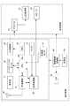
また、図2は、携帯電話機1の機能を示すブロック図である。携帯電話機1は、操作部11と、マイク12と、メインアンテナ40と、RF(Radio Frequency)回路部41と、LCD制御部42と、音声処理部43と、メモリ44と、加速度センサ45と、LED(Light Emitting Diode)46と、電源制御回路部47と、バイブレーションモータ48と、CPU49と、充電池50とが操作部側筐体2に備えられ、LCD表示部21と、スピーカ22と、ドライバIC23とが表示部側筐体3に備えられている。 FIG. 2 is a block diagram showing functions of the
なお、本実施形態では、傾斜センサとして加速度センサ45を利用し、携帯電話機1の傾斜角度を算出する。 In the present embodiment, the
メインアンテナ40は、所定の使用周波数帯(例えば、800MHz)で外部装置と通信を行う。なお、本実施形態では、所定の使用周波数帯として、800MHzとしたが、これ以外の周波数帯であってもよい。また、メインアンテナ40は、所定の使用周波数帯の他に、他の使用周波数帯(例えば、2GHz)に対応できる、いわゆるデュアルバンド対応型による構成であってもよい。 The
RF回路部41は、メインアンテナ40によって受信した信号を復調処理し、処理後の信号をCPU49に供給し、また、CPU49から供給された信号を変調処理し、メインアンテナ40を介して外部装置(基地局)に送信する。また、その一方で、メインアンテナ40によって受信している信号の強度をCPU49に通知を行う。 The
LCD制御部42は、CPU49の制御にしたがって、所定の画像処理を行い、処理後の画像データをドライバIC23に出力する。ドライバIC23は、LCD制御部42から供給された画像データをフレームメモリに蓄え、所定のタイミングでLCD表示部21に出力する。 The
音声処理部43は、CPU49の制御にしたがって、RF回路部41から供給された信号に対して所定の音声処理を行い、処理後の信号をスピーカ22に出力する。スピーカ22は、音声処理部43から供給された信号を外部に出力する。 The audio processing unit 43 performs predetermined audio processing on the signal supplied from the
また、音声処理部43は、CPU49の制御にしたがって、マイク12から入力された信号を処理し、処理後の信号をRF回路部41に出力する。RF回路部41は、音声処理部43から供給された信号に所定の処理を行い、処理後の信号をメインアンテナ40に出力する。 The audio processing unit 43 processes the signal input from the
メモリ44は、例えば、ワーキングメモリを含み、CPU49による演算処理に利用される。具体的には、後述する振動パターンデータを記憶することができる。なお、メモリ44は、着脱可能な外部メモリを兼ねていてもよい。 The
加速度センサ45は、携帯電話機1に与えられた加速度を検出し、検出結果をCPU49に出力する。この加速度センサ45は、傾斜検出手段の一例である。 The
加速度センサ45は、互いに直交するX軸方向、Y軸方向及びZ軸方向の加速度を検出する3軸(3次元)タイプであって、外部から加わった力(F)と質量(m)に基づいて、加速度(a)を測定する(加速度(a)=力(F)/質量(m))。 The
また、加速度センサ45は、例えば、圧電素子によって所定の質量に加わる力を計測して軸ごとの加速度を求め、数値データ化してバッファリングする。そして、CPU49は、周期的にバッファリングされた加速度データを読み出す。なお、加速度センサ45は、圧電素子(圧電式)に限らず、ピエゾ抵抗型、静電容量型、熱検知型等によるMEMS(Micro Electro Mechanical Systems)式や、可動コイルを動かしてフィードバック電流によってもとに戻すサーボ式や、加速度によって生じる歪を歪ゲージによって測定する歪ゲージ式等により構成されてもよい。 Further, the
LED46は、電源制御回路部47から供給される電圧に基づいて発光するように構成されている。なお、図2では、簡単のために、単一のLED46を示すが、実際には後述の図4に示すように複数の異なるLEDを有している。 The
電源制御回路部47は、充電池50が接続されており、充電池50から供給される電源電圧を所定の電源電圧に変換し、変換後の電源電圧をLED46等に供給する。なお、電源制御回路部47は、他の電子部品や機能ブロック等にも電源供給することは勿論のことである。 The power supply
CPU49は、携帯電話機1の全体を制御しており、特に、RF回路部41、LCD制御部42、音声処理部43及びカメラ(図示せず)に対して所定の制御を行う。また、CPU49は、先に述べたメインアンテナ40による電波状態や充電池50の残量、不在着信及び未読メールの有無等の内部状態を監視しており、この結果に基づいて、LED46の発光色を変更したり、LCD表示部21の表示内容を変更したりする制御も行う。 The
また、通信手段としてのRF回路部41により、自装置に対する呼出信号が検出されると、LCD表示部21とLED46とバイブレーションモータ48とスピーカ22とを駆動して、着信を報知する。なお、この着信に対して操作部11による応答操作が生じると、RF回路部41を通信、通話に移行させる。 Further, when a calling signal for the device itself is detected by the
ここで、加速度センサ45とCPU49の動作について説明する。 Here, operations of the
加速度センサ45は、電源制御回路部47から一定の電源電圧が供給されており、携帯電話機1の傾斜が変化する際に、その変化を定期的に加速度データとして検出している。そして、CPU49は、これを読み出す。また、CPU49は、読み出した加速度データに基づいて3軸ごとの傾斜角度を求める所定の演算を行い、携帯電話機1がどの方向に向いているのかを把握する。 The
CPU49は、加速度センサ45が検出した加速度データにより、携帯電話機1の傾斜角度を求め、この傾斜角度に基づいて、LCD表示部21やLED46による演出を制御する。例えば、電話の着信時に、複数設けられたLED46の点灯箇所を傾斜角度に応じて決定したり、ゲーム等のアプリケーションにおいて、傾斜角度に応じて表示画像を変更したりする。 The
ここで、携帯電話機1に搭載した加速度センサ45は、図3に示すように、X軸方向、Y軸方向、Z軸方向の3軸方向の加速度データを検出するものとする。 Here, as shown in FIG. 3, the
次に、加速度センサ45により検出される携帯電話機1の傾斜角度に応じてLED46を制御する方法について説明する。 Next, a method for controlling the
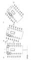
図4は、携帯電話機1が水平面Aに対して垂直に置かれた状態(以下、静止状態という)から、B方向(時計回り方向)に回転させたときのLED46a〜46nの点灯位置を示している。図4(a)では、携帯電話機1は静止状態にあり、LED46a、LED46b、及びLED46nが点灯しており、中心となる位置のLED46aは、濃い色で点灯し、LED46aに隣接するLED46b及びLED46nは、淡い色で点灯している様子を示している。次に、図4(b)は、携帯電話機1が図4(a)の静止状態からB方向(時計回り方向)に回転させたときのLEDの点灯位置を示している。ここでは、LED46a、LED46b、及びLED46cが点灯しており、中心となる位置のLED46bは、濃い色で点灯し、LED46bに隣接するLED46a及びLED46cは、淡い色で点灯している。次に、図4(c)は、携帯電話機1が図4(b)の傾斜状態からさらにB方向(時計回り方向)に回転させたときのLEDの点灯位置を示している。ここでは、LED46b、LED46c、及びLED46dが点灯しており、中心となる位置のLED46cは、濃い色で点灯し、LED46cに隣接するLED46b及びLED46dは、淡い色で点灯している。 FIG. 4 shows the lighting positions of the
本発明に係る携帯電話機1では、テーブルによる方法(加速度センサ45により検出されるX軸、Y軸それぞれの傾斜角度に対応した多数のテーブルを参照することによりLEDの点灯位置を決定する方法)ではなく、加速度センサ45により検出されるX軸方向の加速度値x及びY軸方向の加速度値yに基づいてθ=tan−1(y/x)により算出される偏角θの値によりLEDの点灯位置を決定する。また、加速度センサ45により検出されるX軸方向の加速度値x及びY軸方向の加速度値yに基づいてr=√(x2+y2)により算出される動径rの値によりLEDの点灯する態様を決定する。In the
これにより、制御対象となるLEDの点灯位置を偏角θの値によって決定し、LEDの点灯する態様を動径rの値により決定するため、テーブルを有する必要がない。したがって、簡易な処理で制御対象となるLEDの点灯位置を決定できるため、CPU49の演算処理やメモリ44の容量への負担を低減することができる。 Thereby, since the lighting position of the LED to be controlled is determined by the value of the deviation angle θ and the mode of lighting the LED is determined by the value of the moving radius r, it is not necessary to have a table. Therefore, since the lighting position of the LED to be controlled can be determined by simple processing, it is possible to reduce the burden on the arithmetic processing of the
また、本発明に係る携帯電話機1では、テーブルを参照して制御対象となるLEDの点灯位置を決定するのではなく、偏角θの値に応じて制御対象となるLEDの点灯位置を決定するため、LEDの点灯位置を一意に決定することができる。 In the
図5及び図6を参照して、携帯電話機1の傾斜角度に応じた制御対象となるLEDの点灯位置の制御について説明する。 With reference to FIG.5 and FIG.6, control of the lighting position of LED used as the control object according to the inclination-angle of the
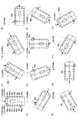
図5は、加速度センサ45により検出された加速度値から算出された偏角θ及び動径rと点灯対象であるLED46a〜46nとの関係を示す図である。図5では、LED46a〜46nの点灯位置は、偏角θの値に応じて±15°刻みでそれぞれ割り当てられている様子を示している。例えば、偏角θの値が0°〜±15°の範囲のときには、LED46a及びLED46nが点灯対象として決定される。 FIG. 5 is a diagram illustrating a relationship between the deflection angle θ and the moving radius r calculated from the acceleration value detected by the
ここで、LED46a〜46nの数と、点灯対象となるLEDを決定するときの範囲角度との関係について考察する。本実施形態においては、図5に示すように、LED46a〜46nの数は合計14である。しかし、図5の例においてはLED46gとLED46h、LED46aとLED46nはそれぞれ同じ制御を行うものであり、実質制御上はLED46gとLED46hで1つ、LED46aとLED46nで1つと扱われ得る。すなわち、点灯制御対象となるLEDの数は実質12である。この数12にて360°を等分すると、30°(すなわち±15°)となり、本実施形態ではこれを範囲角度として取り扱うことにより、傾きの量に応じて発光するLEDを違和感無く特定することができるものである。以下にその具体例を示す。 Here, the relationship between the number of
図6は図5に示す関係から、偏角θ及び動径rの値に基づいて決定された制御対象となるLED46a〜46nの点灯位置を示す。例えば、図6(1)は、偏角θの値が0°〜15°及び345°〜360°の範囲のときには、LED46a及びLED46nが点灯対象として決定され、LED46aとLED46nとが点灯している様子を示している。また、図6(2)は、偏角θの値が15°〜45°の範囲のときには、LED46bが点灯することが表されている。また、図6(3)は、偏角θの値が45°〜75°の範囲のときには、LED46cが点灯することが表されている。また、図6(4)は、偏角θの値が75°〜105°の範囲のときには、LED46dが点灯することが表されている。また、図6(5)は、偏角θの値が105°〜135°の範囲のときには、LED46eが点灯することが表されている。また、図6(6)は、偏角θの値が135°〜165°の範囲のときには、LED46fが点灯することが表されている。また、図6(7)は、偏角θの値が165°〜195°の範囲のときには、LED46g及びLED46hが点灯することが表されている。また、図6(8)は、偏角θの値が195°〜225°の範囲のときには、LED46iが点灯することが表されている。また、図6(9)は、偏角θの値が225°〜255°の範囲のときには、LED46jが点灯することが表されている。また、図6(10)は、偏角θの値が255°〜285°の範囲のときには、LED46kが点灯することが表されている。また、図6(11)は、偏角θの値が285°〜315°の範囲のときには、LED46lが点灯することが表されている。また、図6(12)は、偏角θの値が315°〜345°の範囲のときには、LED46mが点灯することが表されている。 FIG. 6 shows the lighting positions of the
また、LEDの点灯態様は、動径rの値に応じて決定される。ここで、動径rの最大値rmaxと最小値rminが予め定められており、動径rの値がrmin以上であり、rmax以下である場合(rmin≦r≦rmax)には、CPU49は、携帯電話機1の傾斜角度がLED46a〜46nの点灯位置を決定できる範囲内であると判断して、偏角θの値に応じたLEDの点灯位置を決定する。また、動径rの値がrmin未満である場合(r<rmin)には、CPU49は、携帯電話機1の傾斜角度が微小な傾斜であると判断して、所定の態様でLEDを点灯させる(例えば、LED46a〜46nを全て消灯させる)。また、動径rの値がrmaxより大きい場合(r>rmax)には、CPU49は、携帯電話機1の傾斜角度が大きすぎるため、LED46a〜46nの点灯位置を決定できる範囲外であると判断して、所定の態様でLEDを点灯させる(例えば、LED46a〜46nを全て点灯させる)。The lighting mode of the LED is determined according to the value of the moving radius r. Here, the maximum value rmax and the minimum value rmin of the moving radius r are determined in advance, and the value of the moving radius r is not less than rmin and not more than rmax (rmin ≦ r ≦ rmax ). The
なお、上述の説明では、制御対象となるLEDの点灯位置は、偏角θの値に応じて等間隔(±15°ごと)に割り当てられているものとしたが、特にこれに限られない。また、本実施形態では、LED46a〜LED46nの配置間隔が、LED46a〜LED46g及びLED46h〜LED46nでは等間隔であるが、LEDの配置間隔が等間隔でない場合でも、偏角θの値を割り当てる間隔をLEDの配置間隔に対応させることで、簡易にLEDの点灯位置を決定できる。 In the above description, the lighting positions of the LEDs to be controlled are assigned at regular intervals (every ± 15 °) according to the value of the deviation angle θ, but are not limited thereto. Further, in this embodiment, the arrangement intervals of the
本発明に係る携帯電話機1では、このように、制御対象となるLEDの点灯位置を偏角θ及び動径rの値に基づいて決定することで、LEDの点灯位置を一意に決定することができる。また、簡易な処理で制御対象となるLEDの点灯位置を決定でき、CPU49の演算処理やメモリ44の容量への負担を低減することができる。さらに、制御対象となるLEDの点灯位置を、従来のようにテーブルを用いて決定するのではなく、偏角θの値に応じて決定することにより、LEDの個数を変動させた場合でも、仕様の変更を容易に行うことができる。 In the
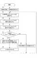
図7は、本発明に係る携帯電話機1の制御対象となるLED点灯位置決定の制御方法の流れを示すフローチャートである。 FIG. 7 is a flowchart showing a flow of a control method for determining the LED lighting position to be controlled by the
初めに、ステップS1では、使用する変数を定義する。ここで、X軸方向の加速度値をx_accと定義し、Y軸方向の加速度値をy_accと定義し、Z軸方向の加速度値をz_accと定義する。また、X軸方向の加速度値及びY軸方向の加速度値に基づく極座標を(r,θ)と定義する。また、動径rの最大値をrmax、動径rの最小値をrminと定義する。First, in step S1, variables to be used are defined. Here, the acceleration value in the X-axis direction is defined as x_acc, the acceleration value in the Y-axis direction is defined as y_acc, and the acceleration value in the Z-axis direction is defined as z_acc. Further, polar coordinates based on the acceleration value in the X-axis direction and the acceleration value in the Y-axis direction are defined as (r, θ). Further, the maximum value of the moving radius r is defined as rmax , and the minimum value of the moving radius r is defined as rmin .
次に、ステップS2では、CPU49は、加速度センサ45により検出される加速度値x_acc、y_acc及びz_accを取得する。 Next, in step S <b> 2, the
ステップS3では、CPU49は、ステップS2で取得したx_acc及びy_accに基づいてr=√((x_acc)2+(y_acc)2)により動径rの値を算出する。ここで、極座標系において、(x_acc)2+(y_acc)2=r2が成り立つことから、r=√((x_acc)2+(y_acc)2)により動径rの値を算出することができる。In step S3, the
ステップS4では、CPU49は、ステップS2で取得したx_acc及びy_accに基づいてθ=tan−1(y_acc/x_acc)により偏角θの値を算出する。ここで、極座標系において、tanθ=y_acc/x_accが成り立つことから、θ=tan−1(y_acc/x_acc)により偏角θの値を算出することができる。In step S4, the
ステップS5では、CPU49は、ステップS3で取得した動径rの値がrminからrmaxの間であるか否か判定する。動径rの値がrminからrmaxの間である場合(YES)には、携帯電話機1がある傾斜をもって保持される状態であると判断して、ステップS6へ移る。一方、動径rの値がrminからrmaxの間にない場合(No)には、携帯電話機1のそれぞれの検出軸における加速度が大きすぎるため、携帯電話機1が静止状態にないと判断して、ステップS7へ移る。In step S5, the
ステップS6では、CPU49は、ステップS4で算出した偏角θ及びステップS2で取得したZ軸方向の加速度値z_accに基づいてLED点灯位置を決定する。ここで、z_accは、携帯電話機1の上下方向の向き(図3、図4、及び図6における紙面裏表方向、つまりLED46a〜46nの配される面が鉛直方向に対して上向きか、下向きか)の判定に用いられる。本工程においては、携帯電話機1の傾斜角度がLED46a〜46nの点灯位置を決定できる範囲外であるので、例えば、携帯電話機1の操作部側筐体2及び表示部側筐体3の両面にLEDを設け、表示部側筐体3が上面にあるときのz_accを正の値とし、また、表示部側筐体3が下面にあるときのz_accを負の値と設定すると、閉状態では操作部側筐体2と表示部側筐体3とのいずれかが鉛直上向きか判定し、上面にあるときに該当する筐体面に設けられたLEDを点灯するように制御することができる。 In step S6, the
ステップS7では、CPU49は、所定の態様でLEDを動作させる。例えば、LEDを全て点灯させたり、LEDを全て消灯させたりする等の態様でLEDを動作させる。そして、所定の態様でLEDを動作させた後、ステップS2へ戻る。 In step S7, the
ステップS8では、CPU49は、ステップS4で決定された偏角θの値及びz_accの値の正、負に応じた位置のLEDを点灯させ、ステップS2へ戻る。 In step S8, the
このようにして、本発明に係る携帯電話機1によれば、加速度センサ45により検出されるX軸方向の加速度値x及びY軸方向の加速度値yに基づいてθ=tan−1(y/x)により算出される偏角θの値よりLEDの点灯位置を決定することができ、また、加速度センサ45により検出されるX軸方向の加速度値x及びY軸方向の加速度値yに基づいてr=√(x2+y2)により算出される動径rの値によりLEDの点灯する態様を決定することができる。すなわち、加速度センサの出力値に基づいて、静止状態にあるか否かを判定し、静止状態又はそれに近い状態のときには、どのような傾斜角度にて保持されるかを判断し、LEDの点灯態様を高速に決定できる。Thus, according to the
なお、上述した本実施形態においては、連続する一連の動作において、LEDの点灯位置の決定に際して、偏角θと動径rに基づいて行うと説明したが、特にこれに限られない。例えば、初回の動作についてのみ本発明による方法を採用し、以降の連続する動作については、その他の方法(例えば、偏角θのみを参考にして、点灯位置の決定を行う)を採用してもよい。このような構成にすることにより、CPU49の負担を軽減することができ、消費電力の低減を図ることができる。 In the present embodiment described above, it has been described that the determination of the lighting position of the LED is performed based on the deviation angle θ and the moving radius r in a series of continuous operations, but is not limited thereto. For example, the method according to the present invention is adopted only for the first operation, and other methods (for example, the lighting position is determined with reference to only the deflection angle θ) for the subsequent continuous operations. Good. With such a configuration, the burden on the
また、表示制御方法によっては、LED等の表示態様を、携帯電話機1の保持状態の変化に伴う加速度の発生時に、その加速度の内容に応じた表示処理を行うという制御方法もある。すなわち、第1の状態から第2の状態に遷移する際の加速度をもって、加速度の向きと大きさを判断して表示制御している。この場合、第1の状態がいかなる状態に有るのか、すなわち加速度がほとんど無いときの状態(基準状態)の判定をすることができない。本発明は、初期位置(基準とする状態)の特定を高速に行うことができるため、このような加速度に基づいての制御、いわば状態遷移時の差分制御方式に対して非常に有用である。特に、加速度センサを用いる場合には、加速度を特定するデバイスであるため、その時々の加速度(動き)を特定し、特定された動きの分、前の表示態様に変化を与える方式での表示制御が容易であるといえる。本発明は、テーブルに照らし合わせて初期位置を特定する場合に比して、非常に高速に初期位置を特定できるため、加速度に基づいたリニアな表示制御処理との組み合わせにより、スムーズな表示制御を提供することができる。 In addition, depending on the display control method, there is a control method in which display processing such as LEDs is performed according to the content of the acceleration when an acceleration occurs due to a change in the holding state of the
以上、本発明の実施形態について説明したが、本発明は上述した実施形態に限るものではない。また、本発明の実施形態に記載された効果は、本発明から生じる最も好適な効果を列挙したに過ぎず、本発明による効果は、本発明の実施形態に記載されたものに限定されるものではない。 As mentioned above, although embodiment of this invention was described, this invention is not restricted to embodiment mentioned above. The effects described in the embodiments of the present invention are only the most preferable effects resulting from the present invention, and the effects of the present invention are limited to those described in the embodiments of the present invention. is not.
例えば、本発明においては、3軸の検出軸を有する加速度センサを例に用いて説明したが、Z軸方向に関しては省略してもよい。すなわち、少なくとも直交する2軸を検出軸として有する加速度センサであれば、本発明は実施可能である。また、表示態様の一例として、複数配されたLEDの点灯を個別制御するものを示したが、これに限定されるものではなく、LCD表示器等の表示デバイスに描画される画像に変化を与えることによって、本発明を実施可能であることは言うまでもない。すなわち、360°を等分した所定の範囲角を予め特定しておき、加速度値に基づいて算出された偏角θの値が、どの範囲角に属するか判定する処理までは複数のLEDの点灯態様を異ならせる場合と共通である。その後、偏角θの属する範囲角に応じて異なる表示を行うようにすることにより実現可能である。また、一度このような表示態様による動作を行った後に、加速度値の検出に応じて、表示内容を変化させることによって、表示態様の変化を継続させることも可能である。 For example, in the present invention, an acceleration sensor having three detection axes has been described as an example, but the Z-axis direction may be omitted. That is, the present invention can be implemented as long as the acceleration sensor has at least two orthogonal axes as detection axes. In addition, as an example of the display mode, an example in which lighting of a plurality of LEDs is individually controlled has been shown. However, the display mode is not limited to this, and an image drawn on a display device such as an LCD display is changed. Of course, the present invention can be implemented. That is, a plurality of LEDs are turned on until a predetermined range angle obtained by equally dividing 360 ° is specified in advance, and the range angle calculated based on the acceleration value belongs to which range angle is determined. This is the same as the case of different aspects. Thereafter, it is possible to realize by performing different display depending on the range angle to which the deflection angle θ belongs. It is also possible to continue the change of the display mode by changing the display content in accordance with the detection of the acceleration value after once performing the operation according to such a display mode.
1 携帯電話機
2 操作部側筐体
3 表示部側筐体
11 操作部
12 マイク
21 LCD表示部
22 スピーカ
23 ドライバIC
40 メインアンテナ
41 RF回路部
42 LCD制御部
43 音声処理部
44 メモリ
45 加速度センサ
46a〜46n LED
47 電源制御回路部
48 バイブレーションモータ
49 CPU
50 充電池
100 携帯電話機
101 表示部側筐体
102a〜102n LEDDESCRIPTION OF
40
47 Power
50
Claims (5)
Translated fromJapanese少なくとも互いに直交するX軸方向の加速度値xとY軸方向の加速度値yをそれぞれ検出する加速度センサと、前記加速度センサにより検出された、前記加速度値xと、前記加速度値yとに応じて前記表示手段の制御を行う制御手段と、を備える携帯電子機器であって、
前記制御手段は、
前記加速度センサにより検出された加速度値x及び加速度値yに基づいてθ=tan−1(y/x)の式を満たす偏角θの値を算出する偏角算出手段と、
前記加速度値x及び前記加速度値yに基づいてr=√(x2+y2)の式を満たす動径rの値を算出する動径算出手段を備え、
前記動径rが所定値を超えたと判定した場合には、前記偏角θの値にかかわらず前記表示手段を第1の表示態様で動作させ、前記動径rが所定値を超えないと判定した場合には、前記偏角θの値に基づいて前記表示手段を第2の表示態様で動作させることを特徴とする携帯電子機器。Display means;
An acceleration sensor that detects at least an acceleration value x in the X-axis direction and an acceleration value y in the Y-axis direction that are orthogonal to each other, and the acceleration value x detected by the acceleration sensor and the acceleration value y according to the acceleration value y A portable electronic device comprising a control means for controlling the display means,
The control means includes
Declination calculating means for calculating a declination θ value satisfying the equation θ = tan−1 (y / x) based on the acceleration value x and the acceleration value y detected by the acceleration sensor;
Aradius vector calculating means for calculating a radius radius r satisfying an equation ofr = √ (x2+ y2)based on the acceleration value x and the acceleration value y;
When it is determined that the radius r exceeds a predetermined value, the display means is operated in the first display mode regardless of the value of the deviation angle θ, and it is determined that the radius r does not exceed the predetermined value. In this case, the display device is operated in the second display mode based on the value of the deviation angle θ .
前記制御手段は、前記偏角θの値及び前記加速度センサにより検出された前記加速度値zに基づいて前記表示手段の動作を前記第2の表示態様とするか、当該第2の表示態様と異なる他の表示態様とするかを決定することを特徴とする請求項1に記載の携帯電子機器。The acceleration sensor detects an acceleration value z in a Z-axis direction orthogonal to the X-axis direction and the Y-axis direction;
The control means sets the operation of the display means to the second display mode based on the value of the deflection angle θ and the acceleration value z detected by the acceleration sensor, or is different from the second display mode. The portable electronic device according to claim1 , wherein it is determined whether to use another display mode.
前記第2の表示態様による前記表示手段の動作を行った後、新たに検出される加速度値に基づいて、前記表示手段の表示態様を前記第2の表示態様から順次変更することを特徴とする請求項1に記載の携帯電子機器。The control means includes
After the operation of the display unit according to the second display mode, the display mode of the display unit is sequentially changed from the second display mode based on a newly detected acceleration value. The portable electronic device according to claim1 .
前記制御手段は、前記第2の表示態様による制御を行う際、前記偏角θが、360°を前記発光素子の数にて分割した範囲角度のいずれかに属するか判定し、判定された範囲角度に基づいて前記複数の発光素子のいずれかを発光させることを特徴とする請求項1から3のいずれか一項に記載の携帯電子機器。The display means includes a plurality of light emitting elements,
The control means determines whether the declination angle θ belongs to one of the range angles obtained by dividing 360 ° by the number of light emitting elements when performing the control according to the second display mode. the portable electronic device according to any one of claims1 to3, characterized in that emit any of the plurality of light emitting elements based on the angle.
前記加速度値x及び前記加速度値yに基づいてr=√(x2+y2)の式を満たす動径rの値を算出する動径算出工程と、を備え、
動作制御工程は、前記動径rが所定値を超えたと判定した場合には、前記偏角θの値にかかわらず表示手段を第1の表示態様で動作させ、前記動径rが所定値を超えないと判定した場合には、前記偏角θの値に基づいて前記表示手段を第2の表示態様で動作させる動作制御工程と、を備える携帯電子機器の制御方法。Based on the acceleration value x in the X-axis direction and the acceleration value y in the Y-axis direction detected by an acceleration sensor that detects accelerations in the X-axis direction and the Y-axis direction orthogonal to each other, θ = tan−1 ( a declination calculating step of calculating a declination value θ satisfying the equation y / x);
Aradius vector calculation step of calculating a radius radius value r satisfying the equation ofr = √ (x2+ y2)based on the acceleration value x and the acceleration value y,
In the operation control step, when it is determined that the moving radius r exceeds a predetermined value, the display means is operated in the first display mode regardless of the value of the deflection angle θ, and the moving radius r is set to the predetermined value. A control method for a portable electronic device, comprising:an operation control stepof operating the display unit in a second display mode based on the value of the deviation angle θ when it is determined that the value does not exceed .
Priority Applications (1)
| Application Number | Priority Date | Filing Date | Title |
|---|---|---|---|
| JP2007281755AJP4980199B2 (en) | 2007-10-30 | 2007-10-30 | Portable electronic device and control method thereof |
Applications Claiming Priority (1)
| Application Number | Priority Date | Filing Date | Title |
|---|---|---|---|
| JP2007281755AJP4980199B2 (en) | 2007-10-30 | 2007-10-30 | Portable electronic device and control method thereof |
Publications (2)
| Publication Number | Publication Date |
|---|---|
| JP2009111706A JP2009111706A (en) | 2009-05-21 |
| JP4980199B2true JP4980199B2 (en) | 2012-07-18 |
Family
ID=40779726
Family Applications (1)
| Application Number | Title | Priority Date | Filing Date |
|---|---|---|---|
| JP2007281755AExpired - Fee RelatedJP4980199B2 (en) | 2007-10-30 | 2007-10-30 | Portable electronic device and control method thereof |
Country Status (1)
| Country | Link |
|---|---|
| JP (1) | JP4980199B2 (en) |
Families Citing this family (3)
| Publication number | Priority date | Publication date | Assignee | Title |
|---|---|---|---|---|
| JP5569952B2 (en)* | 2009-09-03 | 2014-08-13 | Necカシオモバイルコミュニケーションズ株式会社 | Charging apparatus, charging system, and program |
| JP5701115B2 (en)* | 2011-03-16 | 2015-04-15 | 京セラ株式会社 | Electronics |
| KR101580198B1 (en)* | 2013-05-02 | 2015-12-24 | 고려대학교 산학협력단 | Apparatus and method for location tracking |
Family Cites Families (5)
| Publication number | Priority date | Publication date | Assignee | Title |
|---|---|---|---|---|
| JPH10200618A (en)* | 1997-01-13 | 1998-07-31 | Kazunori Tsukiki | Input device |
| JP4320766B2 (en)* | 2000-05-19 | 2009-08-26 | ヤマハ株式会社 | Mobile phone |
| JP2005303432A (en)* | 2004-04-07 | 2005-10-27 | Matsushita Electric Ind Co Ltd | Mobile terminal and mobile terminal control method |
| JP4025752B2 (en)* | 2004-06-28 | 2007-12-26 | 埼玉日本電気株式会社 | Mobile phone and backlight control method thereof |
| JP2006208566A (en)* | 2005-01-26 | 2006-08-10 | Nec Corp | Liquid crystal display apparatus, mobile communication terminal device and liquid crystal display method |
- 2007
- 2007-10-30JPJP2007281755Apatent/JP4980199B2/ennot_activeExpired - Fee Related
Also Published As
| Publication number | Publication date |
|---|---|
| JP2009111706A (en) | 2009-05-21 |
Similar Documents
| Publication | Publication Date | Title |
|---|---|---|
| KR20170089664A (en) | Rollable mobile device and method for controlling the same | |
| KR20150083445A (en) | A method and an electronic device for automatically changing shape based on an event | |
| JP4885807B2 (en) | Portable electronic devices | |
| JP4980199B2 (en) | Portable electronic device and control method thereof | |
| EP3009912B1 (en) | Terminal device and method for controlling operations | |
| CN107396275B (en) | A kind of amplitude detecting device, method and mobile terminal | |
| KR20170004160A (en) | Mobile terminal and method for controlling the same | |
| JP5543077B2 (en) | Portable electronic devices | |
| JP2009080745A (en) | Electronic equipment, information input method and information input control program, handwriting input pen, and portable terminal device | |
| CN108566490A (en) | Screen control method and device of terminal, readable storage medium and terminal | |
| JP2015211336A (en) | Portable electronic apparatus, control method, and program | |
| JP2006065507A (en) | Vibration transmission mechanism, method for creating vibration waveform data, input device with touch function, and electronic device | |
| EP3882756B1 (en) | Electronic apparatus | |
| JP2005332118A (en) | Portable terminal and information inputting method of portable terminal | |
| JP2009109336A (en) | Portable electronic device and control method thereof | |
| JP5084556B2 (en) | Portable electronic devices | |
| JP4805892B2 (en) | Portable electronic devices | |
| US20200142492A1 (en) | Haptic effects using a high bandwidth thin actuation system | |
| KR20170043775A (en) | Input device for touch screen and display apparatus having touch screen | |
| KR101792516B1 (en) | Iot device, mobile terminal and method for controlling the iot device with vibration pairing | |
| KR102858138B1 (en) | Electronic device having a flexible display | |
| JP5301174B2 (en) | Portable electronic device and control method | |
| JP2012128668A (en) | Electronic device | |
| JP5526112B2 (en) | Portable electronic device and display control method | |
| KR101537629B1 (en) | Mobile terminal and method for controlling the same |
Legal Events
| Date | Code | Title | Description |
|---|---|---|---|
| A621 | Written request for application examination | Free format text:JAPANESE INTERMEDIATE CODE: A621 Effective date:20101027 | |
| A977 | Report on retrieval | Free format text:JAPANESE INTERMEDIATE CODE: A971007 Effective date:20111125 | |
| A131 | Notification of reasons for refusal | Free format text:JAPANESE INTERMEDIATE CODE: A131 Effective date:20111129 | |
| A521 | Written amendment | Free format text:JAPANESE INTERMEDIATE CODE: A523 Effective date:20120124 | |
| TRDD | Decision of grant or rejection written | ||
| A01 | Written decision to grant a patent or to grant a registration (utility model) | Free format text:JAPANESE INTERMEDIATE CODE: A01 Effective date:20120321 | |
| A01 | Written decision to grant a patent or to grant a registration (utility model) | Free format text:JAPANESE INTERMEDIATE CODE: A01 | |
| A61 | First payment of annual fees (during grant procedure) | Free format text:JAPANESE INTERMEDIATE CODE: A61 Effective date:20120418 | |
| FPAY | Renewal fee payment (event date is renewal date of database) | Free format text:PAYMENT UNTIL: 20150427 Year of fee payment:3 | |
| R150 | Certificate of patent or registration of utility model | Ref document number:4980199 Country of ref document:JP Free format text:JAPANESE INTERMEDIATE CODE: R150 | |
| LAPS | Cancellation because of no payment of annual fees |