JP4979343B2 - Humidity control system for inside and outside air - Google Patents
Humidity control system for inside and outside airDownload PDFInfo
- Publication number
- JP4979343B2 JP4979343B2JP2006292051AJP2006292051AJP4979343B2JP 4979343 B2JP4979343 B2JP 4979343B2JP 2006292051 AJP2006292051 AJP 2006292051AJP 2006292051 AJP2006292051 AJP 2006292051AJP 4979343 B2JP4979343 B2JP 4979343B2
- Authority
- JP
- Japan
- Prior art keywords
- air
- heat exchanger
- sensible heat
- humidity
- humidifier
- Prior art date
- Legal status (The legal status is an assumption and is not a legal conclusion. Google has not performed a legal analysis and makes no representation as to the accuracy of the status listed.)
- Active
Links
Images


Landscapes
- Central Air Conditioning (AREA)
- Air Conditioning Control Device (AREA)
Description
Translated fromJapanese本発明は、天井内又は機械室に顕熱交換器と加熱加湿器を直列に設置し、顕熱交換器により内・外気を予熱し、加熱加湿器によりさらに加熱を行い、高温低湿空気にすることにより、効率よく気化式の水加湿を行い、顕熱交換器によりアフター冷却することにより、室内よりあまり温度を高くせず湿度の高い供給空気を取り入れる内・外気の調湿システムに関する。In the present invention, a sensible heat exchanger and a heating humidifier are installed in series in the ceiling or in a machine room, the inside and outside air are preheated by the sensible heat exchanger, and further heated by the heating humidifier to form high-temperature and low-humidity air. In particular, the present invention relates to a humidity control system for inside and outside air that efficiently evaporates water and performs after-cooling with a sensible heat exchanger to take in high-humidity supply air without raising the temperature of the room.
一般的にほとんどの家庭やビルにおいて冷房、暖房などの温度調節が行われるが温度調節のみ行うと、空気中の相対湿度が極端に低くなる場合があり、静電気の発生や居住者等の喉の痛みなどの障害が発生し、また、特に病弱な人が所在する病院や高精度の製品の生産を要求される最先端工場では加湿が必要となる。従来、この種の従来の技術の第1の例としては、特開2001−91020の公開特許公報に開示された調湿換気装置に係る技術がある。
これについて説明すれば、図11に示すように屋内機1は、略直方形状に形成された屋内機ケーシング2を備えている。この屋内機ケーシング2は、外気3を導入するための外気導入口4と、吸い込んだ外気3を給気5として室内側に排出する室内側排出口6と、室内空気7を導入するための室内空気導入口8と、吸い込んだ室内空気7を排気9として室外に排出するための室外側排出口10とを備えている。屋内機ケーシング2の内部は中空を形成しており、外気導入口4から室内側排出口6に至る給気経路11および室内空気導入口8から室外側排出口10に至る排気経路12が形成されている。外気導入口4の内方には、導入した外気3を濾過するためのフィルタ13が設けられている。フィルタ13のさらに内方には、後述の冷媒回路を構成する屋内熱交換器14が配置されている。この屋内熱交換器14は、連絡配管接続部15を有しており、この連絡配管接続部15を介して連絡配管と接続され冷媒回路を構成する。冷媒回路中において屋内熱交換器14が凝縮器として作用する場合に、外気3を除湿する除湿器としてはたらく。屋内熱交換器14のさらに内方には、顕熱交換器16が設けられている。この顕熱交換器16は、給気経路11と排気経路12とにわたって設けられており、両経路を通過する空気が非接触で熱交換を行えるように構成されている。顕熱交換器16の排気経路12における室内側には、室内空気7を濾過するためのフィルタ13が設けられている。顕熱交換器16のさらに内方には、加湿器17が配置されている。この加湿器17は、複数本の透湿膜パイプを互いに平行に並設し、この透湿膜パイプの周囲に加湿水を配して構成された透湿膜加湿器で構成される。室内側排出口6の近傍には、給気ファン18が設けられている。この給気ファン18は、回転軸と交わる方向に送風を行うクロスフローファンで構成され、ファンモータ20により回転駆動されることによって、外気導入口4から室内側排出口6に至る給気経路11に気流を生成する。室内空気導入口8の近傍には、排気ファン19が設けられている。排気ファン19は給気ファン18と同様のクロスフローファンで構成され、ファンモータ20により回転駆動されることによって、室内空気導入口8から室外側排出口10に至る排気経路12に気流を生成する。屋外機は、屋外機ケーシングを備えており、内部機構は通常のセパレート型空気調和機の室外機と同様の構成となっている。屋内機1と屋外機とは冷媒経路を構成するための連絡配管およびデータの送受信を行うための内外伝送線によって接続されている。連絡配管は、屋内機1の屋内熱交換器14に設けられる連絡配管接続部15に接続され、屋外機の内部に配置される屋外熱交換器などに接続されている。屋内機ケーシング2の連絡配管接続部近傍には、周囲の温湿度を検出するための温度センサおよび湿度センサが設けられている。Generally, temperature adjustment such as cooling and heating is performed in most homes and buildings. However, if only temperature adjustment is performed, the relative humidity in the air may become extremely low. Injuries such as pain occur, and humidification is necessary in hospitals where sick people are located and in cutting-edge factories that require production of high-precision products. Conventionally, as a first example of this type of conventional technology, there is a technology related to a humidity control ventilator disclosed in Japanese Patent Application Laid-Open No. 2001-91020.
If it demonstrates about this, as shown in FIG. 11, the
次に、この種の従来の技術の第2の例としては特開2002−349905公開特許公報に開示された暖房対応型デシカント空調装置に係る技術がある。これについて説明すれば、このデシカント空調装置21は、図12に示すように、給気経路及び排気経路となる向流型の2つの流路22、23と、これら2つの流路22、23に跨って設置された除湿器24及び顕熱交換器25と、流路23上の顕熱交換器25と除湿器24との間に設置された再生用ヒータ26と、2つの流路22、23のエア導入側及びエア導出側にそれぞれ接続されて各流路22、23を室内または屋外にそれぞれ交互に切り替えて連通させる第1流通切替弁27及び第2流通切替弁28とを備えている。第1の流通切替弁27と流路22及び流路23との間はそれぞれ流路29及び流路30で結ばれ、第2の流通切替弁28と流路22及び流路23との間は、それぞれ流路31及び流路32で結ばれている。第2の流通切替弁28と室内または屋外とはそれぞれ流路33及び流路34により結ばれている。調湿用の加湿器35は、第2流通切換弁28と室内とを結ぶ流路33上に設置される。この流路33には外気を強制的に室内へ送給するための給気ファン36も設けられている。他方、第2流通切換弁28と屋外とを結ぶ流路34上には、室内空気を強制的に屋外へ送給するための排気ファン37が設けられている。この装置の冷房時の運転状況について説明する。冷房時は、図12に示すように、屋外からの外気は、第1の流通切替弁27から流路29に送られ、向流する一方の流路22に導入される。他方、室内空気は同じく第1の流通切替弁27を通じて流路30に送られて、向流する他方の流路23に導入される。一方の流路22に導入された外気は除湿器24と接触して除湿される。他方、他方の流路23に導入された室内空気は顕熱交換器25と接触し、冷熱が回収される。回収された冷熱は、当該顕熱交換器25を通じて、一方の流路22を流通する除湿済みの外気に供与される。顕熱交換器25により冷却された外気は、流路31を通って第2の流通切替弁28に送られる。第2の流通切替弁28に送られた外気は、流路33に送られて、加湿器35によって調湿された後、室内に送給される。他方、冷熱が回収された室内空気は、除湿器24と顕熱交換器25との間に介設されたヒータ26により加熱されて、除湿器24と接触して除湿器24を加熱再生する。その後、室内空気は流路32を通って第2の流通切替弁28に送られ、そこから流路34を通じて屋外に排出される。Next, as a second example of this type of conventional technique, there is a technique related to a heating-compatible desiccant air conditioner disclosed in Japanese Patent Application Laid-Open No. 2002-349905. If this is demonstrated, this
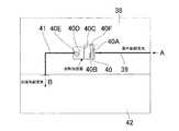
また、この種の従来の技術の他の例としては、図13に示す屋外新鮮空気導入型加湿システムがある。これについて説明すれば、外部から天井38内へ屋外新鮮空気Aを給気管39を通じて該天井38内に配置した加熱加湿器40に導入する。この加熱加湿器40の働きにより排気管41を介して空調室42内に加湿供給空気Bを排出し、該空調室42内の調湿動作を行なう。ここに、前記加熱加湿器40は給気管39側から空気ろ過フィルター40A、加熱コイル40B、加湿部40C、エリミネーター40D及び送風機40Eを備えている。また、該加湿部40Cは給気管付湿度制御バルブ40Fを接続している。この屋外新鮮空気導入型加湿システムによれば、室外の新鮮な空気Aを前記加熱加湿器40により加熱して水を気化させる方式であり、空調室42内に加湿された空気Bを流送する。この技術は加湿供給空気の温度がおよそ40℃以下では加湿効率が悪く空調室42内の空気を設計湿度例えば40(%)で維持することが困難であり、しかも前記加湿部40Cへ供給する水量が比較的多量であった。
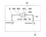
また、この種の従来の技術の更に他の例としては、図14に示す室内低湿度空気導入型加湿システムがある。これについて説明すれば、空調室42内から天井38内へ室内低湿度空気Cを供給管39を通じて該天井38内に配置した加熱加湿器40に導入する。この加熱加湿器40の働きにより排気管41を介して空調室42内に加湿供給空気Dを排出し、該空調室42内の調湿動作を行なう。ここに、前記加熱加湿器40は給気管39側から空気ろ過フィルター40A、加熱コイル40B、加湿部40C、エリミネーター40D及び送風機40Eを備えている。また、該加湿部40Cは給気管付湿度制御バルブ40Fを接続している。この室内低湿度空気導入型加湿システムによれば、室内低湿度空気Cを前記加熱加湿器40により加熱して水を気化させる方式である。空調室42内に加湿された空気Dを流送する。この技術は加湿効率が悪く空調室42内の空気を設計湿度例えば40(%)で維持することが困難であり、しかも前記加湿部40Cへ供給する水量が比較的多量であった。
As still another example of this type of conventional technology, there is an indoor low-humidity air introduction type humidification system shown in FIG. To explain this, indoor low-humidity air C is introduced from the air-
従来の技術に於ける第1に例によれば、室外からの空気を室内側に供給するための給気経路と、室内空気を室外側に排出するための排気経路と、給気経路内に配置される給気ファンと、排気経路内に配置される排気ファンと、給気経路内に配置され、室外からの空気を加湿する加湿器と、屋内熱交換器、四路切換弁、アキュムレータ、圧縮機、屋外熱交換器、減圧器を含む冷媒回路とを備え、冷媒回路の屋内熱交換器が給気経路内に配置され、加湿器による加湿量が不足する場合に、屋内熱交換器を凝縮器として冷媒回路を暖房運転する加湿アシストモードを備えた調湿換気装置であって、加湿アシストモードによる運転を開始した後、一定時間の間は前記圧縮機の機能を制限することを特徴とする。
また、従来の技術に於ける第2の例によれば、給気経路及び排気経路には、これら両経路に跨って除湿器および顕熱交換器が設けられている。除湿器は、冷房時に給気経路に取り込まれた外気を除湿する。除湿された外気は顕熱交換器へと送給される。また、顕熱交換器は、冷房時に、除湿された外気と排気経路に取り込まれた室内空気との間で熱交換をする。つまり、屋外へ排出される室内空気から冷熱を回収して室内へと送り込まれる外気に付与する。顕熱交換器により冷却された外気は、途中、加湿器により調湿された後、室内へと放出される。顕熱交換器により冷熱が回収された室内空気は除湿器へ送られる。この室内空気は、除湿器へと向かう途中、顕熱交換器と除湿器との間に設置された再生用ヒータにより加熱される。加熱された室内空気は、除湿器と接触して当該除湿器を加熱再生した後、屋外へと排出される。
而して、前記第1及び第2の例では、調湿換気装置及び空調装置に具備している顕熱交換器16、25は外気又は室内気を当該顕熱交換器16、25に流送し、これに加湿作用を奏し、そのまま室内排出口6や室外側排出口10に又は給気ファン36や排気ファン37等を介して排出し、空調作用を行なう技術である。
従って、特に、最近の建物は断熱性が良いことと内部発熱が多いため暖房負荷が少ないため、給気温度は室内温度とほぼ同程度となる傾向となり、室温に近い空気に気化加湿をしているので、大変加湿効率が悪いという問題点があった。
また湿度を満足させようとすると、暖房負荷に比べて給気温度が高くなりすぎて、室内温度が高くなる問題点があった。
また、図13及び図14に示す従来の技術によれば、いずれも顕熱交換器を備えておらず、この技術は加湿効率が悪く空調室42内の空気を設計湿度例えば40(%)で維持することが困難であり、しかも前記加湿部40Cへ供給する水量が比較的多量であり、供給水量が増大するという弊害もあった。
本発明が解決しようとする課題は、背景技術で述べた問題点を解決することにある。According to a first example in the prior art, an air supply path for supplying outdoor air to the indoor side, an exhaust path for discharging indoor air to the outdoor side, and an air supply path An air supply fan that is disposed; an exhaust fan that is disposed in the exhaust path; a humidifier that is disposed in the air supply path and humidifies air from outside; an indoor heat exchanger; a four-way selector valve; an accumulator; A refrigerant circuit including a compressor, an outdoor heat exchanger, and a decompressor, and when the indoor heat exchanger of the refrigerant circuit is disposed in the air supply path and the humidification amount by the humidifier is insufficient, the indoor heat exchanger is A humidity control ventilator equipped with a humidification assist mode for heating a refrigerant circuit as a condenser, characterized by limiting the function of the compressor for a certain period of time after starting the operation in the humidification assist mode. To do.
Further, according to the second example in the prior art, the air supply path and the exhaust path are provided with a dehumidifier and a sensible heat exchanger over both these paths. The dehumidifier dehumidifies the outside air taken into the air supply path during cooling. The dehumidified outside air is sent to the sensible heat exchanger. Further, the sensible heat exchanger exchanges heat between the dehumidified outside air and the indoor air taken into the exhaust path during cooling. That is, cold heat is collected from the indoor air discharged to the outside and applied to the outside air sent into the room. The outside air cooled by the sensible heat exchanger is conditioned by a humidifier and then released into the room. The room air from which cold heat has been recovered by the sensible heat exchanger is sent to the dehumidifier. The room air is heated by a regeneration heater installed between the sensible heat exchanger and the dehumidifier on the way to the dehumidifier. The heated indoor air comes into contact with the dehumidifier and heats and regenerates the dehumidifier, and is then discharged to the outdoors.
Thus, in the first and second examples, the
Therefore, in particular, recent buildings have good heat insulation properties and a large amount of internal heat generation, so the heating load is small. Therefore, the supply air temperature tends to be almost the same as the room temperature. Therefore, there was a problem that the humidification efficiency was very bad.
Further, when trying to satisfy the humidity, there is a problem that the supply air temperature becomes too high as compared with the heating load and the room temperature becomes high.
Further, according to the conventional technique shown in FIGS. 13 and 14, none of them is provided with a sensible heat exchanger, and this technique has poor humidification efficiency, and the air in the air-conditioned
The problem to be solved by the present invention is to solve the problems described in the background art.
本発明に係る内・外気の調湿システムは顕熱交換器と加熱加湿器を巧みに組み合わせている。まず、外気または室内空気を顕熱交換器により予熱し、加熱加湿器によりさらに加熱を行い、高温低湿空気にすることにより効率よく気化式の水加湿を行うことが可能となる。その後顕熱交換器でアフター冷却することにより、低温高湿空気をつくることが可能となり、このシステムは、湿度を上げたいが室温を上げたくない状況において、大変有効であり、無駄な給水を大幅に削減でき省エネルギーとなる技術であって、次の構成、手段から成立する。
すなわち、請求項1記載の発明によれば、天井内又は機械室内に設置された顕熱交換器と、該顕熱交換器の後段に配置した加熱加湿器であって、該加熱加湿器が空気ろ過フィルター、加熱コイル、湿度制御バルブ付給水管を接続した加湿部、エリミネータ及び供給ファンを順次配置してなり、屋外新鮮空気Eを加湿前に予熱する該顕熱交換器に導入し、該顕熱交換器で熱交換させて取出された外気Fを前記加熱加湿器に流過し該加熱加湿器から流出した外気Gを前記顕熱交換器で再熱交換させた後、空調室内に所期する物理条件を充足した加湿供給空気を取入れることを特徴とする。The inside / outside air humidity control system according to the present invention skillfully combines a sensible heat exchanger and a heating humidifier. First, the outdoor air or indoor air is preheated by a sensible heat exchanger, further heated by a heating humidifier, and converted to high-temperature and low-humidity air, whereby vaporization-type water humidification can be efficiently performed. After cooling with a sensible heat exchanger, it becomes possible to produce low-temperature and high-humidity air. This system is very effective in situations where you want to increase humidity but do not want to increase room temperature, and greatly reduce wasteful water supply. This technology can be reduced to energy savings and consists of the following configurations and means.
That is, according to the first aspect of the present invention, there is provideda sensible heat exchangerinstalled in the ceiling or in the machine room,and a heating humidifierdisposed in a subsequent stage ofthe sensible heat exchanger, wherein the heating humidifieris air. A humidifier, eliminator, and supply fan connected to a filtration filter, heating coil, water supply pipe with humidity control valve are sequentially arranged, and fresh outdoor air E is introduced into the sensible heat exchanger that preheats before humidification. After the outside air F taken out by heat exchange with the heat exchanger flows through the heating humidifier, the outside air G that flows out of the heating humidifier is reheat-exchanged with the sensible heat exchanger, and then the inside of the air conditioning room is expected. It is characterized by taking in the humidified supply air that satisfies the physical conditions.
請求項2記載の発明によれば、天井内又は機械室内に設置された顕熱交換器と、該顕熱交換器の後段に配置した加熱加湿器であって、該加熱加湿器が空気ろ過フィルター、加熱コイル、湿度制御バルブ付給水管を接続した加湿部、エリミネータ及び供給ファンを順次配置してなり、室内低湿度空気Jを加湿前に予熱する該顕熱交換器に導入し、該顕熱交換器で熱交換させて取出された内気Fを前記加熱加湿器に流過し該加熱加湿器から流出した内気Gを前記顕熱交換器で再熱交換させた後、空調室内に所期する物理条件を充足した加湿供給空気を取入れることを特徴とする。According to invention of
本発明に係る内・外気の調湿システムは、叙上の構成、作用を有するので次の効果がある。
すなわち、請求項1記載の発明によれば、天井内又は機械室内に設置された顕熱交換器と、該顕熱交換器の後段に配置した加熱加湿器であって、該加熱加湿器が空気ろ過フィルター、加熱コイル、湿度制御バルブ付給水管を接続した加湿部、エリミネータ及び供給ファンを順次配置してなり、屋外新鮮空気Eを加湿前に予熱する該顕熱交換器に導入し、該顕熱交換器で熱交換させて取出された外気Fを前記加熱加湿器に流過し該加熱加湿器から流出した外気Gを前記顕熱交換器で再熱交換させた後、空調室内に所期する物理条件を充足した加湿供給空気を取入れることを特徴とする内・外気の調湿システムを提供する。
このような構成としたので、顕熱交換器により屋外新鮮空気Eを加湿前に予熱し、加熱加湿器によりさらに加熱を行い、その後顕熱交換器でアフター冷却することにより、低温高湿空気をつくることが可能となり、このシステムは、湿度を上げたいが室温を上げたくない状況において、大変有効であり、無駄な給水を大幅に削減でき省エネルギーを実現でき、殊に飽和効率を低くすることで加湿を容易にし、加湿有効率が高めることにより消費される給水量を削減でき、前記加熱加湿器が空気ろ過フィルター、加熱コイル、湿度制御バルブ付給水管を接続した加湿部、エリミネータ及び供給ファンでコンパクトに構成され外気を合理的に加湿すると共にエリミネータにより外気つまり屋外新鮮空気に包含する水分を適正に除去できアフター冷却により、温度が低く相対湿度が高い空気を空調室内に供給可能とするという効果がある。The inside / outside air humidity control system according to the present invention has the following effects because it has the above-described configuration and action.
That is, according to the first aspect of the present invention, there is provideda sensible heat exchangerinstalled in the ceiling or in the machine room,and a heating humidifierdisposed in a subsequent stage ofthe sensible heat exchanger, wherein the heating humidifieris air. A humidifier, eliminator, and supply fan connected to a filtration filter, heating coil, water supply pipe with humidity control valve are sequentially arranged, and fresh outdoor air E is introduced into the sensible heat exchanger that preheats before humidification. After the outside air F taken out by heat exchange with the heat exchanger flows through the heating humidifier, the outside air G that flows out of the heating humidifier is reheat-exchanged with the sensible heat exchanger, and then the inside of the air conditioning room is expected. Provided is a humidity control system for inside and outside air, which is characterized by incorporating humidified supply air that satisfies the physical conditions to be performed.
With such a structure, the outdoor fresh air E is preheated by the sensible heat exchanger before humidification, further heated by the heating humidifier, and then cooled by the sensible heat exchanger, so that the low temperature and high humidity air is This system is very effective in situations where you want to increase humidity but do not want to increase room temperature, which can greatly reduce wasteful water supply and save energy, especially by reducing saturation efficiency. Humidification is facilitated and the amount of water supply consumed can be reduced by increasing the humidification effectiveness rate. Theheating humidifier is composed of an air filtration filter, a heating coil, a humidifier connected to a water supply pipe with a humidity control valve, an eliminator and a supply fan. After coolingcan properly remove water include the outside air, i.e. outside fresh air by eliminator with reasonably humidified outside air is made compact Accordingly, there is an effect that the relative humidity temperature is low is to be supplied with highair conditioned room.
請求項2記載の発明によれば、天井内又は機械室内に設置された顕熱交換器と、該顕熱交換器の後段に配置した加熱加湿器であって、該加熱加湿器が空気ろ過フィルター、加熱コイル、湿度制御バルブ付給水管を接続した加湿部、エリミネータ及び供給ファンを順次配置してなり、室内低湿度空気Jを加湿前に予熱する該顕熱交換器に導入し、該顕熱交換器で熱交換させて取出された内気Fを前記加熱加湿器に流過し該加熱加湿器から流出した内気Gを前記顕熱交換器で再熱交換させた後、空調室内に所期する物理条件を充足した加湿供給空気を取入れることを特徴とする内・外気の調湿システムを提供する。
このような構成としたので、顕熱交換器により室内低湿度空気Jを加湿前に予熱し、加熱加湿器によりさらに加熱を行い、その後顕熱交換器でアフター冷却することにより、低温高湿空気をつくることが可能となり、このシステムは、湿度を上げたいが室温を上げたくない状況において、大変有効であり、無駄な給水を大幅に削減でき省エネルギーを実現でき、殊に飽和効率を低くすることで加湿を容易にし、加湿有効率が高めることにより消費される給水量を削減でき、前記加熱加湿器が空気ろ過フィルター、加熱コイル、湿度制御バルブ付給水管を接続した加湿部、エリミネータ及び供給ファンでコンパクトに構成され内気を合理的に加湿すると共にエリミネータにより内気つまり室内低温度空気に包含する水分を適正に除去できアフター冷却により、温度が低く相対湿度が高い空気を空調室内に供給可能とするという効果がある。According to invention of
Because of this structure, low-temperature high-humidity air is obtained by preheating indoor low-humidity air J with a sensible heat exchanger before humidification, further heating with a heating humidifier, and then aftercooling with a sensible heat exchanger. This system is very effective in situations where you want to increase humidity but not room temperature, and can greatly reduce wasted water supply and save energy, especially reducing saturation efficiency. Thehumidification unit, eliminator and supply fan with which the heating humidifier is connected with an air filtration filter, heating coil, and water supply pipe with humidity control valve can be reduced. aphthouscan properly remove water include shy i.e. room low temperature air by eliminator with in configured compactly reasonably humidified room air The cooling has the effect of enabling supply temperature relative humidity low highair conditioned room.
以下、本発明に係る内・外気の調湿システムの実施の形態について、添付図面に基づき詳細に説明する。DESCRIPTION OF EMBODIMENTS Hereinafter, embodiments of a humidity control system for inside and outside air according to the present invention will be described in detail with reference to the accompanying drawings.
図1は、本発明に係る内・外気の調湿システムの実施の形態を示すもので該システムを建物の内部に配置した構成図である。FIG. 1 shows an embodiment of a humidity control system for inside and outside air according to the present invention, and is a configuration diagram in which the system is arranged inside a building.
43は建物の天井又は機械室である。44は該建物の空調室である。建物の外部から矢印Eで示す屋外新鮮空気を導入配管等で導入する。導入された屋外新鮮空気Eは顕熱交換器45に流送される。該顕熱交換器45では、図2の本発明に係る模式図に示すように、顕熱交換器45と加熱加湿器46を直列に配置し、加湿前に空気の温度を予熱で高くすることにより、飽和効率を低くすることで加湿を容易にし、加湿有効率が高めることにより消費される給水量を削減でき、しかもアフター冷却により、一般的に難しいとされる温度が低く相対湿度が高い空気を供給可能とする。ここで飽和効率とは加湿による空気の状態変化の中で相対湿度100%の飽和点に至るまでの加湿のし易さを表わすものである。43 is a ceiling of a building or a machine room.
例えば、加湿により空気の相対湿度を10%上げる場合において、相対湿度80%を90%にする場合と相対湿度20%を30%にする場合を比較すると、相対湿度20%を30%にする場合の方が飽和効率の数値が低くなり、加湿が容易であることを示す。そして、例えば図1のシステムにおける図3、図4の設計仕様1で言えば、加湿前の導入気体Q0の温度を0(℃)から22.9(℃)に温度を高くするに伴い、相対湿度が50(%)から11(%)となり、さらに加熱加湿器46における加熱コイルで加熱された時の空気は温度が50(℃)で相対湿度が2(%)と相対湿度を低くした後に加湿をし、空気温度が38.3(℃)で相対湿度が16(%)となった時の飽和効率は、0.38となる。同様な加湿を従来技術である図13の方式で行った場合における飽和効率は、0.73であり、本システムにおいては従来技術に比べ飽和効率が大変低くなり、加湿が容易となることがわかる。また、加湿が容易となることにより、加湿有効率が高められ消費される給水量を削減でき、しかもアフター冷却により、一般的に難しいとされる温度が低く相対湿度が高い空気例えば温度が15.4(℃)、相対湿度が60(%)の空気を供給可能とする。For example, when the relative humidity of air is increased by 10% by humidification, when the relative humidity of 80% is set to 90% and the relative humidity of 20% is set to 30%, the relative humidity of 20% is set to 30%. This indicates that the value of saturation efficiency is lower, and humidification is easier. For example, in the
図2に示すように、該導入気体Q0と流出気体Q1の熱交換作用を行っている。そして、図2では、当該導入気体Q0つまり室内供給空気が該顕熱交換器45の本体45A内に流過し、熱交換され供給ファン45Bを経て矢印P1に示すように加熱加湿器46に導入される。該加熱加湿器46から流出気体Q1つまり室内供給空気は矢印P2に示すように該顕熱交換器45の本体45A内に流過し、熱交換され、排出ファン45Cを経て加湿供給空気としての流出気体Q1が排出する。このように排気する空気の熱回収目的ではなく、同一空気を顕熱交換器45で直列利用することにより、予熱で飽和効率を低くして加湿効率を上げ、アフター冷却により温度が低く相対湿度が高い空気を得ることが可能となることを特徴としている。As shown in FIG. 2, it is performed heat exchange action of the outflow gas Q1 and the introduction gas Q0. In FIG. 2, the introduced gas Q0, that is, the indoor supply air flows into the
ここで翻って図1に示すように、前記屋外新鮮空気Eは非加湿空気であって、前記顕熱交換器45外気Gとの熱交換により予熱され、外気Fとして加熱加湿器46に流送される。該顕熱交換器45は屋外新鮮空気Eとしての外気Fを流出し、該加熱加湿器46に流送する。該加熱加湿器46は、供給ファン46a、エリミネーター46b、加湿部46c、加熱コイル46d、空気ろ過フィルター46e及び該加湿部46cに接続した湿度制御バルブ付給水管46fを備えている。
そこで流送された外気Fは該加熱加湿器46における前記加熱コイル46dを経由して、前記加湿部46cで加湿され、外気Fに包含する水分は前記エリミネーター46eにより除去し、前記供給ファン46aを介して矢印Gに示すように流出する。そこで外気Gは前記顕熱交換器45で再熱交換され矢印Hに示すように流出する。
外気Hは空調室44内へ加湿供給空気Iとして取入れる。該加湿供給空気Iは所期する物理条件、すなわち乾球温度と絶対湿度または相対湿度に設定され、得られる。Here, as shown in FIG. 1, the outdoor fresh air E is non-humidified air, which is preheated by heat exchange with the outside air G of the
The outside air F sent there is humidified by the
The outside air H is taken into the
次に、図1に示す本発明に係る内・外気の調湿システムの実施の形態の構成に於ける設計仕様1及び2についてその作用等を図3、図4に基づき説明する。先づ、設計仕様1は空調室で暖房時に加湿する場合であり、それについて説明する。Next, the operation of the
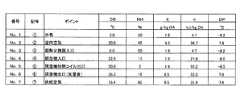
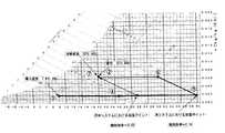
外気としての屋外空気Eが図3及び図4に示すように、乾球温度(DB)を0(℃)、相対湿度(RH)を50(%)に設定したとき(No.1)、絶対湿度(X)は1.9(g/kg・DA)であり、前記屋外新鮮空気Eは1000(m3/時間)の流量であって、前記顕熱交換器45で外気Gとの熱交換により予熱され外気Fとして、加熱加湿器46に流送される。予熱され外気Fは、乾球温度(DB)が22.9(℃)、相対湿度(RH)が11(%)、絶対湿度(X)が1.9(g/kg・DA)となる(No.4)。そのときの空調室44内の室内空気は乾球温度(DB)が20(℃)、相対湿度(RH)が45(%)、絶対湿度(X)が6.5(g/kg・DA)である(No.2)。該加熱加湿器46は屋外新鮮空気Fとしての外気Gを流出し、該顕熱交換器45に流送する。このとき外気Gは乾球温度(DB)が38.3(℃)、相対湿度(RH)が16(%)及び絶対湿度(X)が6.5(g/kg・DA)である(No.6)。さらに外気Gは前記顕熱交換器45で外気Eとの熱交換によりアフター冷却され外気Hとなり、空調室44内へ加湿供給空気Iとして取入れられる。外気Hおよび加湿供給空気Iは、乾球温度(DB)が15.4(℃)、相対湿度(RH)が60(%)、絶対湿度(X)が6.5(g/kg・DA)となる(No.7)該加熱加湿器46は、供給ファン46a、エリミネーター46b、加湿部46c、加熱コイル46d、空気ろ過フィルター46e及び該加湿部46eに接続した湿度制御バルブ付給水管46fを備えている。そこで流送された外気Fは前記加熱コイル46dを介して流入し、加湿部46cを経て、外気Fに包含する水分は前記エリミネーター46bにより除去し、供給ファン46aを介して加熱加湿器46の外へ流出する。When the outdoor air E as the outside air is set to 0 (° C.) and the relative humidity (RH) to 50 (%) as shown in FIGS. The humidity (X) is 1.9 (g / kg · DA), the outdoor fresh air E has a flow rate of 1000 (m3 / hour), and heat exchange with the outside air G is performed by the
このときの加熱加湿器46、つまり調湿機内の内部において、外気Fは加熱加湿器の加熱コイル46dで加熱され、乾球温度(DB)が50(℃)、相対湿度(RH)が2(%)、絶対湿度(X)が1.9(g/kg・DA)でとなる(No.5)。さらに該加熱加湿器46の加熱加湿器の加湿部で加湿され外気Gとなる。外気Gは、乾球温度(DB)が38.3(℃)、相対湿度(RH)が16(%)及び絶対湿度(X)が6.5(g/kg・DA)となる(No.6)。該加熱加湿器46から流出した外気Gは顕熱交換器45の入口となり、そこで外気Eとの熱交換によりアフター冷却され矢印Hに示すように流出する。外気Hは空調室44内へ加湿供給空気Iとして取入れる。このときの加湿供給空気Iは乾球温度(DB)が15.4(℃)、相対湿度(RH)が60(%)、絶対湿度(X)が6.5(g/kg・DA)である(No.7)。該加湿供給空気Iは所期する物理条件、すなわち乾球温度および絶対湿度または相対湿度に設定され、得られる。この設計仕様1における試算では、室内設定状態である乾球温度(DB)が20.0(℃)、絶対湿度(X)が6.5(g/kg・DA)に対し、該加湿供給空気Iは、乾球温度(DB)が15.4(℃)、絶対湿度(X)が6.5(g/kg・DA)となり、冷却加湿が可能となる。
その他の物理的条件は、例えばエンタルピーh(KJ/kg・DA)、結露温度(DP)(℃)は図3に示すとおりで、顕熱交換器の熱交換率は60%とした。
この設計仕様1における飽和効率は、0.38である。同様な加湿を従来技術である図13の方式で行った場合における飽和効率は、0.73であり、本システムにおいては従来技術に比べ飽和効率が大変低くなり、加湿が容易となることがわかる。また、加湿が容易となることにより、加湿有効率が高められ消費される給水量を削減でき、しかもアフター冷却により、一般的に難しいとされる温度が低く相対湿度が高い空気例えば温度が15.4(℃)、相対湿度が60(%)の空気を供給可能とする。
そして、一般的な論理としては、調湿装置では図5に示すように、空気(外気)乾球温度が高いとき、湿度量も高く、逆に、空気(外気)乾球温度が低いとき、加湿量も低くなることが判明している。At this time, inside the
Other physical conditions are, for example, enthalpy h (KJ / kg · DA), dew condensation temperature (DP) (° C.) as shown in FIG. 3, and the heat exchange rate of the sensible heat exchanger was 60%.
The saturation efficiency in this
And as a general logic, as shown in FIG. 5, when the air (outside air) dry bulb temperature is high, the humidity is also high, and conversely, when the air (outside air) dry bulb temperature is low, It has been found that the amount of humidification is also reduced.
次に、図1に示す本発明に係る内・外気の調湿システムの実施の形態の構成に於ける設計仕様2についてその作用等を図6、図7に基づいて説明する。設計仕様2は空調室を暖房時に加湿する場合であり、それについて説明する。Next, the operation of the
外気としての屋外空気Eが図6及び図7に示すように、乾球温度(DB)を7.8(℃)、相対湿度(RH)を29(%)に設定したとき(No.1)、絶対湿度(X)は1.9(g/kg・DA)であり、前記屋外新鮮空気Eは1000(m3/時間)の流量であって、前記顕熱交換器45で熱交換され加熱加湿器46に流送される。そのときの空調室44内の室内空気は乾球温度(DB)が20(℃)、相対湿度(RH)が45(%)、絶対湿度(X)が6.5(g/kg・DA)である(No.2)。該加熱加湿器46は屋外新鮮空気Eとしての外気Fを流出し、該加熱加湿器46、すなわち、調湿機に流送する。このとき外気Eは乾球温度(DB)が38.3(℃)、相対湿度(RH)が16(%)及び絶対湿度(X)が6.5(g/kg・DA)である(No.6)。該加熱加湿器46は、供給ファン46a、エリミネーター46b、加湿部46c、加熱コイル46d、空気ろ過フィルター46e及び該加湿部46eに接続した湿度制御バルブ付給水管46fを備えている。そこで流送された外気Fは前記加熱コイル46dを介して流入し、加湿部46cを経て、外気Fに包含する水分は前記エリミネーター46bにより除去し、供給ファン46aを介して加熱加湿器46の外へ流出する。このときの加熱加湿器46、つまり調湿機内部において、外気Fは加熱加湿器の加熱コイル46dで加熱され、つまり調湿機内を流送する外気Fは乾球温度(DB)が50(℃)、相対湿度(RH)が2(%)、絶対湿度(X)が1.9(g/kg・DA)である(No.5)。該加熱加湿器46から流出した外気Gは顕熱交換器45の入口となり、乾球温度(DB)が38.3(℃)、相対湿度(RH)が16(%)及び絶対湿度(X)が6.5(g/kg・DA)である(No.6)。そこで外気Gは前記顕熱交換器45で再熱交換され矢印Hに示すように流出する。外気Hは空調室44内へ加湿供給空気Iとして取入れる。このときの加湿供給空気Iは乾球温度(DB)が20(℃)、相対湿度(RH)が45(%)、絶対湿度(X)が6.5(g/kg・DA)である(No.7)。該加湿供給空気Iは所期する物理条件、すなわち乾球温度および相対湿度または絶対湿度に設定され、得られる。
その他の物理的条件は、例えばエンタルピーh(KJ/kg・DA)、結露温度(DP)(℃)は図6に示すとおりで、顕熱交換器の熱交換率は60%とした。
この設計仕様2における飽和効率は、0.38である。同様な加湿を従来技術である図13の方式で行った場合における飽和効率は、0.63であり、本システムにおいては従来技術に比べ飽和効率が大変低くなり、加湿が容易となることがわかる。また、加湿が容易となることにより、加湿有効率が高められ消費される給水量を削減でき、しかもアフター冷却により、一般的に難しいとされる温度が低く相対湿度が高い空気例えば温度が20(℃)、相対湿度が45(%)の空気を供給可能とする。When the outdoor air E as outside air is set to 7.8 (° C.) dry bulb temperature (DB) and 29 (%) relative humidity (RH) as shown in FIGS. 6 and 7 (No. 1) The absolute humidity (X) is 1.9 (g / kg · DA), the outdoor fresh air E has a flow rate of 1000 (m3 / hour), and heat is exchanged by the
Other physical conditions are, for example, enthalpy h (KJ / kg · DA), dew condensation temperature (DP) (° C.) as shown in FIG. 6, and the heat exchange rate of the sensible heat exchanger was 60%.
The saturation efficiency in this
次に、本発明に係る内・外気の調湿システムに於ける実施例について図8に基づき説明する。Next, an embodiment of the inside / outside air humidity control system according to the present invention will be described with reference to FIG.
図8は、本発明に係る内・外気の調湿システムの実施例を示すシステムを建物の内部に配置した構成図である。FIG. 8 is a configuration diagram in which a system showing an embodiment of a humidity control system for inside and outside air according to the present invention is arranged inside a building.
43は建物の天井又は機械室である。44は該建物の空調室である。空調室44内から矢印Jで示す室内低湿度空気を導入配管等で天井内に設置した顕熱交換器45に導入する。導入された室内低湿度空気Jは顕熱交換器45に流送される。
図8に示すように、前記室内低湿度空気Jは非加湿空気であって、前記顕熱交換器45で熱交換され加熱加湿器46に流送される。該加熱加湿器46は熱交換された室内低湿度空気Fつまり内気を流出し、該加熱加湿器46に流送する。該加熱加湿器46は、空気ろ過フィルター46e、加熱コイル46d、加湿部46c、エリミネーター46b、供給ファン46a及び該加湿部46cに接続した湿度制御バルブ付給水管46fを備えている。そこで流送された外気Fは前記加熱コイル46dを介して流入し、加湿部46cを経て、外気Fに包含する水分は前記エリミネーター46bにより除去し、供給ファン46aを介して矢印Gに示すように流出する。そこで内気Gは前記顕熱交換器45で再熱交換され矢印Hに示すように流出する。内気Hは空調室44内へ加湿供給空気Kとして取入れる。該加湿供給空気Kは所期する物理条件、すなわち乾球温度および相対湿度または絶対湿度に設定され、得られる。43 is a ceiling of a building or a machine room.
As shown in FIG. 8, the indoor low-humidity air J is non-humidified air, and is heat-exchanged by the
次に、図8に示す本発明に係る内・外気の調湿システムの実施例の構成に於ける設計仕様3についてその作用等を図9、図10に基づき説明する。先づ、設計仕様3は空調室で暖房時に加湿する場合であり、それについて説明する。Next, the operation of the
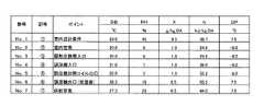
図9及び図10に示すように、空調室44内の設計条件を乾球温度(DB)を20(℃)、相対湿度(RH)を45(%)に設定したとき(No.1)、絶対湿度(X)は6.5(g/kg・DA)であり、室内低湿度空気Jは1000(m3/時間)の流量であって、前記顕熱交換器45で熱交換され加熱加湿器46に流送される。そのときの空調室44内の室内空気は乾球温度(DB)が20(℃)、相対湿度(RH)が8(%)、絶対湿度(X)が1.9(g/kg・DA)である(No.2)。該顕熱交換器45は室内低湿度空気Jとしての内気Fを流出し、該加熱加湿器46、すなわち、調湿機に流送する。このとき内気Fは乾球温度(DB)が38.3(℃)、相対湿度(RH)が16(%)及び絶対湿度(X)が6.5(g/kg・DA)である(No.6)。該加熱加湿器46は、供給ファン46a、エリミネーター46b、加湿部46c、加熱コイル46d、空気ろ過フィルター46e及び該加湿部46eに接続した湿度制御バルブ付給水管46fを備えている。As shown in FIGS. 9 and 10, when the design conditions in the air-
このときの加熱加湿器46、つまり調湿機内部において、内気Fは加熱加湿器の加熱コイル46dで加熱され、乾球温度(DB)が50(℃)、相対湿度(RH)が2(%)、絶対湿度(X)が1.9(g/kg・DA)である(No.5)。該加熱加湿器46から流出した内気Gは顕熱交換器45の入口となり、乾球温度(DB)が38.3(℃)、相対湿度(RH)が16(%)及び絶対湿度(X)が6.5(g/kg・DA)である(No.6)。そこで内気Gは前記顕熱交換器45で再熱交換され矢印Hに示すように流出する。内気Hは空調室44内へ加湿供給空気Kとして取入れる。このときの加湿供給空気Kは乾球温度(DB)が27.3(℃)、相対湿度(RH)が29(%)、絶対湿度(X)が6.5(g/kg・DA)である(No.7)。該加湿供給空気Kは、すなわち乾球温度および相対湿度または絶対湿度に設定され、得られる。
その他の物理的条件は、例えばエンタルピーh(KJ/kg・DA)、結露温度(DP)(℃)は図9に示すとおりで、顕熱交換器の熱交換率は60%とした。
この設計仕様3における飽和効率は、0.38である。同様な加湿を従来技術である図14の方式で行った場合における飽和効率は、0.5であり、本システムにおいては従来技術に比べ飽和効率が大変低くなり、加湿が容易となることがわかる。また、加湿が容易となることにより、加湿有効率が高められ消費される給水量を削減でき、しかもアフター冷却により、一般的に難しいとされる温度が低く相対湿度が高い空気例えば温度が27.3(℃)、相対湿度が29(%)の空気を供給可能とする。Inside the
As other physical conditions, for example, the enthalpy h (KJ / kg · DA), the dew condensation temperature (DP) (° C.) are as shown in FIG. 9, and the heat exchange rate of the sensible heat exchanger is 60%.
The saturation efficiency in this
43 天井(機械室)
44 空調室
45 顕熱交換器
45A 顕熱交換器の本体
45B 顕熱交換器の供給ファン
46 加熱加湿器
46a 加熱加湿器の供給ファン
46b 加熱加湿器のエリミネーター
46c 加熱加湿器の加湿部
46d 加熱加湿器の加熱コイル
46e 加熱加湿器の空気ろ過フィルター
46f 加熱加湿器の湿度制御バルブ付給水管
E 屋外新鮮空気
F 外気(内気)
G 外気(内気)
H 外気(内気)
I 加湿供給空気
J 室内低湿度空気
K 加湿供給空気
43 Ceiling (machine room)
44
G Outside air (Sleep)
H Open air (Sleep)
I Humidification supply air J Indoor low humidity air K Humidification supply air
Claims (2)
Translated fromJapanesePriority Applications (1)
| Application Number | Priority Date | Filing Date | Title |
|---|---|---|---|
| JP2006292051AJP4979343B2 (en) | 2006-10-27 | 2006-10-27 | Humidity control system for inside and outside air |
Applications Claiming Priority (1)
| Application Number | Priority Date | Filing Date | Title |
|---|---|---|---|
| JP2006292051AJP4979343B2 (en) | 2006-10-27 | 2006-10-27 | Humidity control system for inside and outside air |
Publications (2)
| Publication Number | Publication Date |
|---|---|
| JP2008107044A JP2008107044A (en) | 2008-05-08 |
| JP4979343B2true JP4979343B2 (en) | 2012-07-18 |
Family
ID=39440529
Family Applications (1)
| Application Number | Title | Priority Date | Filing Date |
|---|---|---|---|
| JP2006292051AActiveJP4979343B2 (en) | 2006-10-27 | 2006-10-27 | Humidity control system for inside and outside air |
Country Status (1)
| Country | Link |
|---|---|
| JP (1) | JP4979343B2 (en) |
Families Citing this family (4)
| Publication number | Priority date | Publication date | Assignee | Title |
|---|---|---|---|---|
| JP2008164252A (en)* | 2006-12-28 | 2008-07-17 | Sasakura Engineering Co Ltd | Air conditioning facility |
| US9112989B2 (en)* | 2010-04-08 | 2015-08-18 | Qualcomm Incorporated | System and method of smart audio logging for mobile devices |
| CN110864421A (en)* | 2019-11-29 | 2020-03-06 | 宁波奥克斯电气股份有限公司 | Air conditioner control method and system and air conditioner |
| JP7202335B2 (en)* | 2020-09-17 | 2023-01-11 | ダイキン工業株式会社 | air conditioning system |
Family Cites Families (2)
| Publication number | Priority date | Publication date | Assignee | Title |
|---|---|---|---|---|
| JP2000130805A (en)* | 1998-08-18 | 2000-05-12 | Denso Corp | Humidifier |
| JP2002317966A (en)* | 2001-04-20 | 2002-10-31 | Daikin Ind Ltd | Ventilation system |
- 2006
- 2006-10-27JPJP2006292051Apatent/JP4979343B2/enactiveActive
Also Published As
| Publication number | Publication date |
|---|---|
| JP2008107044A (en) | 2008-05-08 |
Similar Documents
| Publication | Publication Date | Title |
|---|---|---|
| KR101746154B1 (en) | Air conditioning system | |
| JP4207166B2 (en) | Dehumidifying air conditioner | |
| KR100504503B1 (en) | air conditioning system | |
| CN110709643B (en) | Ventilation system | |
| US7930896B2 (en) | Air conditioning system | |
| CN201221816Y (en) | Apparatus for dehumidification, purification and air exhausting thermal recovery of indoor fresh wind | |
| US20090229294A1 (en) | Air conditioning system | |
| CN101363649A (en) | Ground source heat pump air conditioning system based on independent control of temperature and humidity | |
| JPH11101520A (en) | Air cycle type air conditioner | |
| CN204629742U (en) | A rotary valve type air purification refrigeration air conditioner | |
| CN105276736A (en) | Heat pump type total heat recovery new-air air conditioning unit with condensation reheating function | |
| WO2010029710A1 (en) | Air conditioner | |
| JP4979343B2 (en) | Humidity control system for inside and outside air | |
| JP3785753B2 (en) | Air conditioner | |
| CN211011666U (en) | A waste heat recovery type fresh air dehumidification unit with high supply air temperature | |
| CN107192013A (en) | Indoor unit and air conditioner with same | |
| JP3265524B2 (en) | Desiccant air conditioner | |
| JP2003294274A (en) | Constant temperature and constant humidity air conditioning system | |
| JP2006317078A (en) | Heat pump air conditioner | |
| JP2003279069A (en) | Desiccant air conditioning system | |
| JP2001056132A (en) | Air conditioner | |
| JP4683548B2 (en) | Desiccant ventilator | |
| JPH0942709A (en) | Desiccant air conditioner | |
| JP2002018230A (en) | Humidity controlling apparatus | |
| JP3023361B1 (en) | Heat exchange type ventilation system |
Legal Events
| Date | Code | Title | Description |
|---|---|---|---|
| A621 | Written request for application examination | Free format text:JAPANESE INTERMEDIATE CODE: A621 Effective date:20091006 | |
| A871 | Explanation of circumstances concerning accelerated examination | Free format text:JAPANESE INTERMEDIATE CODE: A871 Effective date:20110622 | |
| A977 | Report on retrieval | Free format text:JAPANESE INTERMEDIATE CODE: A971007 Effective date:20110706 | |
| A975 | Report on accelerated examination | Free format text:JAPANESE INTERMEDIATE CODE: A971005 Effective date:20110704 | |
| A131 | Notification of reasons for refusal | Free format text:JAPANESE INTERMEDIATE CODE: A131 Effective date:20110720 | |
| A521 | Request for written amendment filed | Free format text:JAPANESE INTERMEDIATE CODE: A523 Effective date:20110915 | |
| A02 | Decision of refusal | Free format text:JAPANESE INTERMEDIATE CODE: A02 Effective date:20111012 | |
| A521 | Request for written amendment filed | Free format text:JAPANESE INTERMEDIATE CODE: A523 Effective date:20111226 | |
| RD02 | Notification of acceptance of power of attorney | Free format text:JAPANESE INTERMEDIATE CODE: A7422 Effective date:20120110 | |
| A911 | Transfer to examiner for re-examination before appeal (zenchi) | Free format text:JAPANESE INTERMEDIATE CODE: A911 Effective date:20120206 | |
| TRDD | Decision of grant or rejection written | ||
| A01 | Written decision to grant a patent or to grant a registration (utility model) | Free format text:JAPANESE INTERMEDIATE CODE: A01 Effective date:20120417 | |
| A01 | Written decision to grant a patent or to grant a registration (utility model) | Free format text:JAPANESE INTERMEDIATE CODE: A01 | |
| A61 | First payment of annual fees (during grant procedure) | Free format text:JAPANESE INTERMEDIATE CODE: A61 Effective date:20120417 | |
| FPAY | Renewal fee payment (event date is renewal date of database) | Free format text:PAYMENT UNTIL: 20150427 Year of fee payment:3 | |
| R150 | Certificate of patent or registration of utility model | Ref document number:4979343 Country of ref document:JP Free format text:JAPANESE INTERMEDIATE CODE: R150 Free format text:JAPANESE INTERMEDIATE CODE: R150 | |
| S531 | Written request for registration of change of domicile | Free format text:JAPANESE INTERMEDIATE CODE: R313531 | |
| R350 | Written notification of registration of transfer | Free format text:JAPANESE INTERMEDIATE CODE: R350 | |
| R250 | Receipt of annual fees | Free format text:JAPANESE INTERMEDIATE CODE: R250 | |
| R250 | Receipt of annual fees | Free format text:JAPANESE INTERMEDIATE CODE: R250 | |
| R250 | Receipt of annual fees | Free format text:JAPANESE INTERMEDIATE CODE: R250 | |
| R250 | Receipt of annual fees | Free format text:JAPANESE INTERMEDIATE CODE: R250 | |
| R250 | Receipt of annual fees | Free format text:JAPANESE INTERMEDIATE CODE: R250 | |
| R250 | Receipt of annual fees | Free format text:JAPANESE INTERMEDIATE CODE: R250 | |
| R250 | Receipt of annual fees | Free format text:JAPANESE INTERMEDIATE CODE: R250 | |
| R250 | Receipt of annual fees | Free format text:JAPANESE INTERMEDIATE CODE: R250 | |
| R250 | Receipt of annual fees | Free format text:JAPANESE INTERMEDIATE CODE: R250 | |
| R250 | Receipt of annual fees | Free format text:JAPANESE INTERMEDIATE CODE: R250 | |
| R250 | Receipt of annual fees | Free format text:JAPANESE INTERMEDIATE CODE: R250 |